Embed Size (px)
Citation preview

052987-051r17 Printed in USA November, 2018
INSTALLATION MANUAL FREEDOM RM AWNING
ROOF MOUNTED BOX AWNINGRV
TABLE OF CONTENTS Product Overview .......................................................................................................................... 1
Component Checklist.............................................................................................................................. 2 Freedom RM Bracket Kits ....................................................................................................................... 3
Installation ..................................................................................................................................... 4 Bracket Installation ................................................................................................................................. 4 Mounting the Awning .............................................................................................................................. 4 Mount Bottom Brackets .......................................................................................................................... 5 Manual Crank Handle Storage Clips ...................................................................................................... 5
Switch Installation (motorized awnings only) ............................................................................. 6
Optional LED Lighting ................................................................................................................... 7 Switch Installation ................................................................................................................................... 7
Pitch Adjustment ........................................................................................................................... 8
Manual Override (motorized Awnings) ........................................................................................ 8
Setting the Motor Limits ............................................................................................................... 9 Adjusting the OUT Limit Switch .............................................................................................................. 9 Adjusting the IN Limit Switch .................................................................................................................. 9

Carefree of Colorado Installation Manual FREEDOM RM PATIO AWNING
PROPRIETARY STATEMENT The Freedom Awning is a product of Carefree of Colorado, located in Broomfield, Colorado, USA. The information contained in or disclosed in this document is considered proprietary to Carefree of Colorado. Every effort has been made to ensure that the information presented in the document is accurate and complete. However, Carefree of Colorado assumes no liability for errors or for any damages that result from the use of this document.
The information contained in this manual pertains to the current configuration of the models listed on the title page. Earlier model configurations may differ from the information given. Carefree of Colorado reserves the right to cancel, change, alter or add any parts and assemblies, described in this manual, without prior notice.
Carefree of Colorado agrees to allow the reproduction of this document for use with Carefree of Colorado products only. Any other reproduction or translation of this document in whole or part is strictly prohibited without prior written approval from Carefree of Colorado.
SAFETY INFORMATION
This is the safety alert symbol. It is used to alert individuals to potential personal injury hazards. Obey all safety messages that follow this symbol to avoid possible personal injury or death.
WARNING Indicates a hazardous situation, which if not avoided, could result in death or serious bodily injury.
CAUTION Indicates a hazardous situation, which if not avoided, may result in minor or moderate bodily injury.
NOTICE Indicates a situation that may result in equipment-related damage.
General Safety:
WARNING This product can expose you to chemicals including Di-isodecyl phthalate (DIDP), Vinyl Chloride and Formaldehyde, which are known to the state of California to cause cancer or birth defects or other reproductive harm. For more information visit www.P65warnings.ca.gov
WARNING Shock Hazard. Always disconnect battery or power source before working on or around the electrical system.
WARNING Always wear appropriate safety equipment (i.e. goggles).
CAUTION Always use appropriate lifting devices and/or helpers when lifting or
holding heavy objects.
NOTICE When using fasteners, do not over tighten. Soft materials such as fiberglass and
aluminum can be "stripped out" and lose the ability to grip and hold.
Carefree of Colorado www.carefreeofcolorado.com a Scott Fetzer company
Carefree of Colorado Installation Manual FREEDOM RM PATIO AWNING
052978-051r17 1
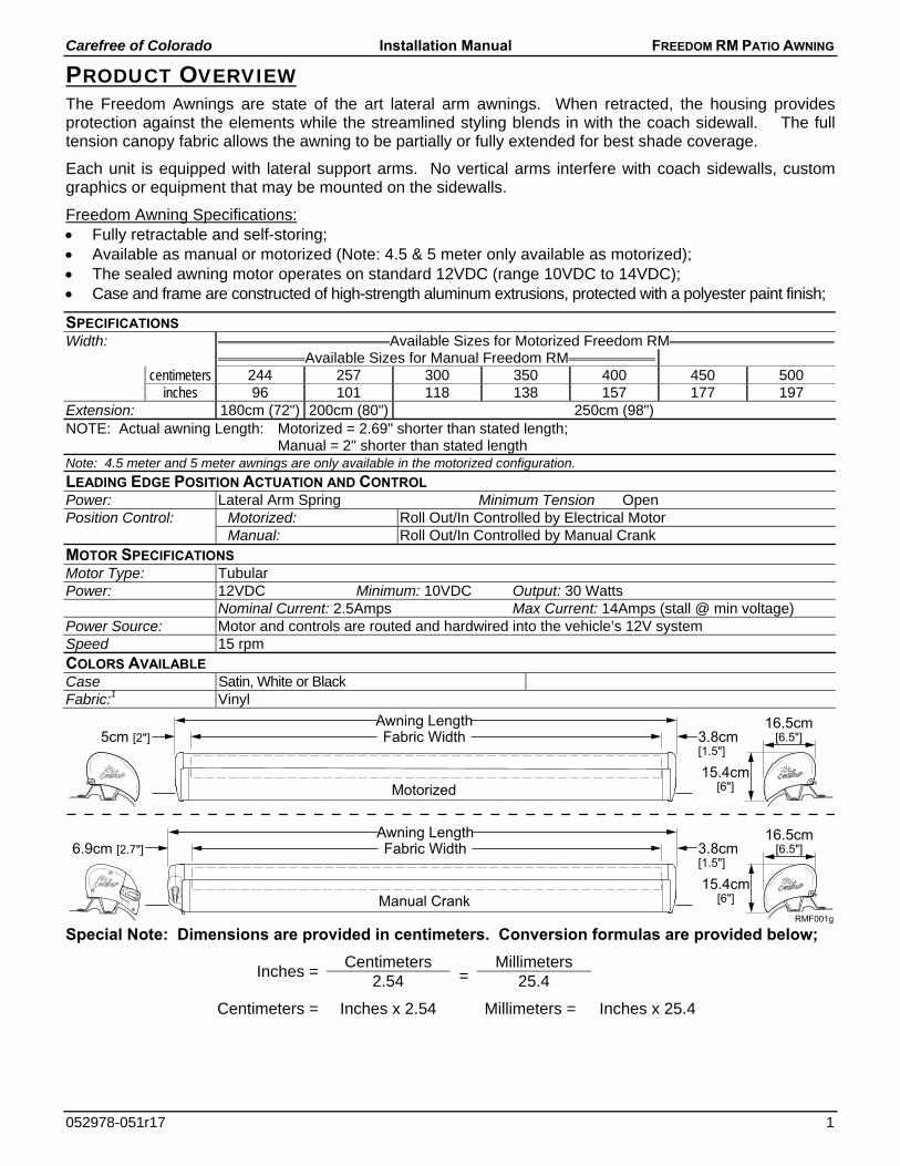
PRODUCT OVERVIEW The Freedom Awnings are state of the art lateral arm awnings. When retracted, the housing provides protection against the elements while the streamlined styling blends in with the coach sidewall. The full tension canopy fabric allows the awning to be partially or fully extended for best shade coverage.
Each unit is equipped with lateral support arms. No vertical arms interfere with coach sidewalls, custom graphics or equipment that may be mounted on the sidewalls.
Freedom Awning Specifications: Fully retractable and self-storing; Available as manual or motorized (Note: 4.5 & 5 meter only available as motorized); The sealed awning motor operates on standard 12VDC (range 10VDC to 14VDC); Case and frame are constructed of high-strength aluminum extrusions, protected with a polyester paint finish;
SPECIFICATIONS Width: Available Sizes for Motorized Freedom RM
Available Sizes for Manual Freedom RM centimeters 244 257 300 350 400 450 500
inches 96 101 118 138 157 177 197 Extension: 180cm (72") 200cm (80") 250cm (98") NOTE: Actual awning Length: Motorized = 2.69" shorter than stated length;
Manual = 2" shorter than stated length Note: 4.5 meter and 5 meter awnings are only available in the motorized configuration.
LEADING EDGE POSITION ACTUATION AND CONTROL Power: Lateral Arm Spring Minimum Tension Open Position Control: Motorized: Roll Out/In Controlled by Electrical Motor Manual: Roll Out/In Controlled by Manual Crank MOTOR SPECIFICATIONS Motor Type: Tubular Power: 12VDC Minimum: 10VDC Output: 30 Watts
Nominal Current: 2.5Amps Max Current: 14Amps (stall @ min voltage) Power Source: Motor and controls are routed and hardwired into the vehicle’s 12V system Speed 15 rpm COLORS AVAILABLE Case Satin, White or Black Fabric:1 Vinyl
Special Note: Dimensions are provided in centimeters. Conversion formulas are provided below;
Inches = Centimeters
=Millimeters
2.54 25.4
Centimeters = Inches x 2.54 Millimeters = Inches x 25.4
RMF001g
Awning LengthFabric Width 3.8cm
[1.5"]5cm [2"]
15.4cm[6"]
16.5cm[6.5"]
Motorized
Awning LengthFabric Width6.9cm [2.7"] 3.8cm
[1.5"]
15.4cm[6"]
16.5cm[6.5"]
Manual Crank
Carefree of Colorado Installation Manual FREEDOM RM PATIO AWNING
2 052978-051r17
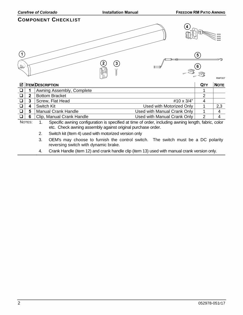
COMPONENT CHECKLIST
ITEM DESCRIPTION QTY NOTE
1 Awning Assembly, Complete 1 2 Bottom Bracket 2 3 Screw, Flat Head #10 x 3/4" 4 4 Switch Kit Used with Motorized Only 1 2,3 5 Manual Crank Handle Used with Manual Crank Only 1 4 6 Clip, Manual Crank Handle Used with Manual Crank Only 2 4 NOTES: 1. Specific awning configuration is specified at time of order, including awning length, fabric, color
etc. Check awning assembly against original purchase order.
2. Switch kit (Item 4) used with motorized version only
3. OEM's may choose to furnish the control switch. The switch must be a DC polarity reversing switch with dynamic brake.
4. Crank Handle (item 12) and crank handle clip (item 13) used with manual crank version only.
RMF007
326
4
51
Carefree of Colorado Installation Manual FREEDOM RM PATIO AWNING
052978-051r17 3
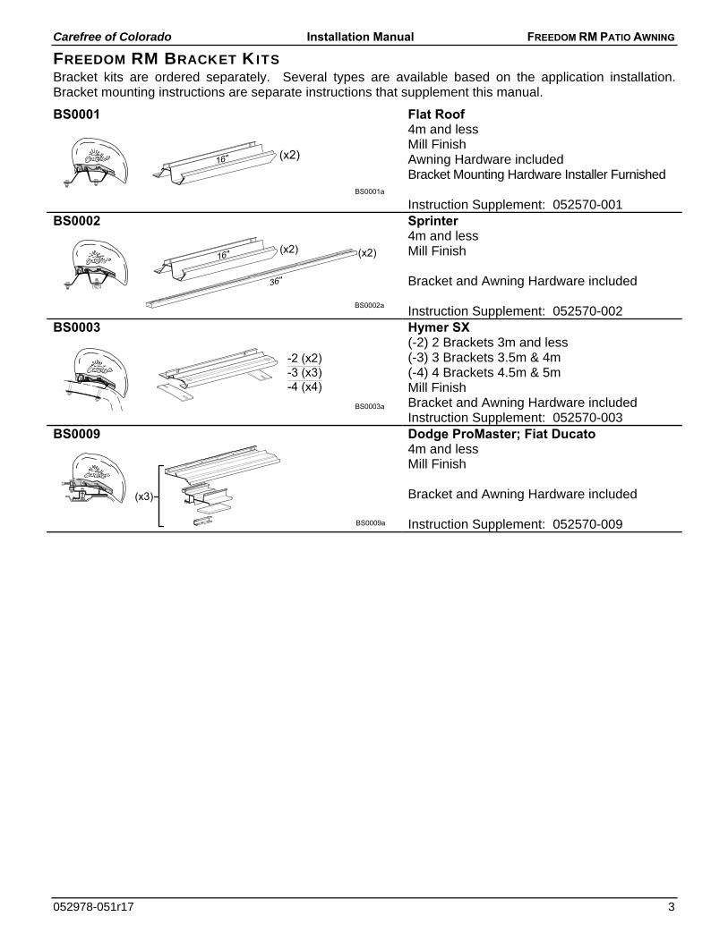
FREEDOM RM BRACKET KITS Bracket kits are ordered separately. Several types are available based on the application installation. Bracket mounting instructions are separate instructions that supplement this manual.
BS0001 Flat Roof
4m and less Mill Finish Awning Hardware included Bracket Mounting Hardware Installer Furnished Instruction Supplement: 052570-001
BS0002 Sprinter
4m and less Mill Finish Bracket and Awning Hardware included Instruction Supplement: 052570-002
BS0003 Hymer SX
(-2) 2 Brackets 3m and less (-3) 3 Brackets 3.5m & 4m (-4) 4 Brackets 4.5m & 5m Mill Finish Bracket and Awning Hardware included Instruction Supplement: 052570-003
BS0009 Dodge ProMaster; Fiat Ducato
4m and less Mill Finish Bracket and Awning Hardware included Instruction Supplement: 052570-009
BS0001a
(x2)16"
(x2) (x2)
36"
BS0002a
16"
BS0003a
-2 (x2)-3 (x3)-4 (x4)
BS0009a
(x3)
Carefree of Colorado Installation Manual FREEDOM RM PATIO AWNING
4 052978-051r17
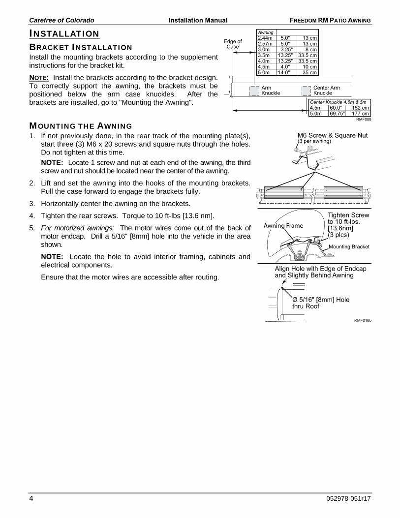
INSTALLATION BRACKET INSTALLATION Install the mounting brackets according to the supplement instructions for the bracket kit.
NOTE: Install the brackets according to the bracket design. To correctly support the awning, the brackets must be positioned below the arm case knuckles. After the brackets are installed, go to "Mounting the Awning".
MOUNTING THE AWNING 1. If not previously done, in the rear track of the mounting plate(s),
start three (3) M6 x 20 screws and square nuts through the holes. Do not tighten at this time.
NOTE: Locate 1 screw and nut at each end of the awning, the third screw and nut should be located near the center of the awning.
2. Lift and set the awning into the hooks of the mounting brackets. Pull the case forward to engage the brackets fully.
3. Horizontally center the awning on the brackets.
4. Tighten the rear screws. Torque to 10 ft-lbs [13.6 nm].
5. For motorized awnings: The motor wires come out of the back of motor endcap. Drill a 5/16" [8mm] hole into the vehicle in the area shown.
NOTE: Locate the hole to avoid interior framing, cabinets and electrical components.
Ensure that the motor wires are accessible after routing.
RMF008
ArmKnuckle
Edge ofCase
Center ArmKnuckle
Awning2.44m 5.0" 13 cm2.57m 5.0" 13 cm3.0m 3.25" 8 cm3.5m 13.25" 33.5 cm4.0m 13.25" 33.5 cm4.5m 4.0" 10 cm5.0m 14.0" 35 cm
Center Knuckle 4.5m & 5m4.5m 60.0" 152 cm5.0m 69.75" 177 cm
RMF016b
M6 Screw & Square Nut(3 per awning)
Ø 5/16" [8mm] Holethru Roof
Align Hole with Edge of Endcapand Slightly Behind Awning
Tighten Screwto 10 ft-lbs.[13.6nm](3 plcs)
Mounting Bracket
Awning Frame
Carefree of Colorado Installation Manual FREEDOM RM PATIO AWNING
052978-051r17 5
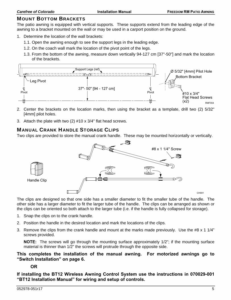
MOUNT BOTTOM BRACKETS The patio awning is equipped with vertical supports. These supports extend from the leading edge of the awning to a bracket mounted on the wall or may be used in a carport position on the ground.
1. Determine the location of the wall brackets:
1.1. Open the awning enough to see the support legs in the leading edge.
1.2. On the coach wall mark the location of the pivot point of the legs.
1.3. From the bottom of the awning, measure down vertically 94-127 cm [37"-50"] and mark the location of the brackets.
2. Center the brackets on the location marks, then using the bracket as a template, drill two (2) 5/32" [4mm] pilot holes.
3. Attach the plate with two (2) #10 x 3/4" flat head screws.
MANUAL CRANK HANDLE STORAGE CLIPS Two clips are provided to store the manual crank handle. These may be mounted horizontally or vertically.
The clips are designed so that one side has a smaller diameter to fit the smaller tube of the handle. The other side has a larger diameter to fit the larger tube of the handle. The clips can be arranged as shown or the clips can be oriented so both attach to the larger tube (i.e. if the handle is fully collapsed for storage).
1. Snap the clips on to the crank handle.
2. Position the handle in the desired location and mark the locations of the clips.
3. Remove the clips from the crank handle and mount at the marks made previously. Use the #8 x 1 1/4” screws provided.
NOTE: The screws will go through the mounting surface approximately 1/2”; if the mounting surface material is thinner than 1/2” the screws will protrude through the opposite side.
This completes the installation of the manual awning. For motorized awnings go to “Switch Installation” on page 6.
OR
If installing the BT12 Wireless Awning Control System use the instructions in 070029-001 “BT12 Installation Manual” for wiring and setup of controls.
RMF004
37"- 50" [94 - 127 cm]
Leg Pivot
Ø 5/32" [4mm] Pilot HoleSupport Legs (ref)
Pivot Pivot
Bottom Bracket
#10 x 3/4"Flat Head Screws(x2)
#8 x 1 1/4" Screw
CH001
Handle Clip
Carefree of Colorado Installation Manual FREEDOM RM PATIO AWNING
6 052978-051r17
SWITCH INSTALLATION (MOTORIZED AWNINGS ONLY)
WARNING Shock Hazard. Always disconnect battery or power source before working on or around the electrical system.
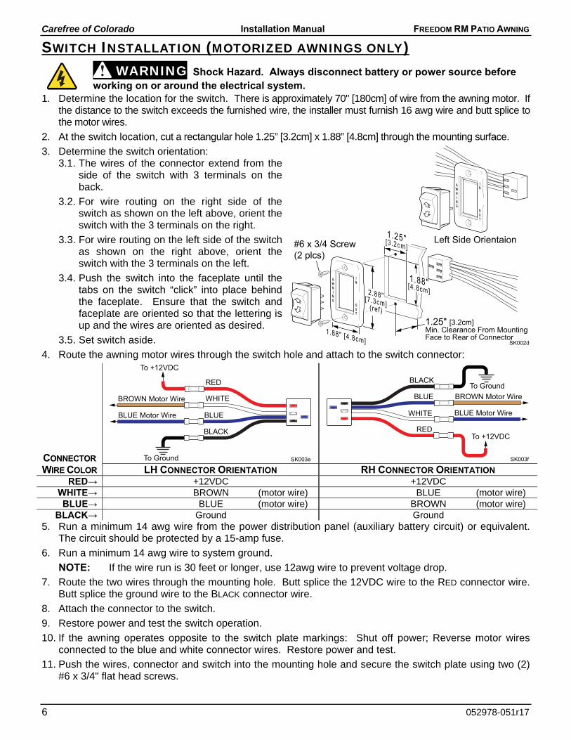
1. Determine the location for the switch. There is approximately 70" [180cm] of wire from the awning motor. If the distance to the switch exceeds the furnished wire, the installer must furnish 16 awg wire and butt splice to the motor wires.
2. At the switch location, cut a rectangular hole 1.25” [3.2cm] x 1.88” [4.8cm] through the mounting surface.
3. Determine the switch orientation: 3.1. The wires of the connector extend from the
side of the switch with 3 terminals on the back.
3.2. For wire routing on the right side of the switch as shown on the left above, orient the switch with the 3 terminals on the right.
3.3. For wire routing on the left side of the switch as shown on the right above, orient the switch with the 3 terminals on the left.
3.4. Push the switch into the faceplate until the tabs on the switch “click” into place behind the faceplate. Ensure that the switch and faceplate are oriented so that the lettering is up and the wires are oriented as desired.
3.5. Set switch aside.
4. Route the awning motor wires through the switch hole and attach to the switch connector:
CONNECTOR
WIRE COLOR LH CONNECTOR ORIENTATION RH CONNECTOR ORIENTATION RED→ +12VDC +12VDC
WHITE→ BROWN (motor wire) BLUE (motor wire) BLUE→ BLUE (motor wire) BROWN (motor wire)
BLACK→ Ground Ground 5. Run a minimum 14 awg wire from the power distribution panel (auxiliary battery circuit) or equivalent.
The circuit should be protected by a 15-amp fuse.
6. Run a minimum 14 awg wire to system ground.
NOTE: If the wire run is 30 feet or longer, use 12awg wire to prevent voltage drop.
7. Route the two wires through the mounting hole. Butt splice the 12VDC wire to the RED connector wire. Butt splice the ground wire to the BLACK connector wire.
8. Attach the connector to the switch.
9. Restore power and test the switch operation.
10. If the awning operates opposite to the switch plate markings: Shut off power; Reverse motor wires connected to the blue and white connector wires. Restore power and test.
11. Push the wires, connector and switch into the mounting hole and secure the switch plate using two (2) #6 x 3/4" flat head screws.
SK003eTo Ground
To +12VDC
BLUE Motor Wire
BROWN Motor Wire
RED
BLACK
WHITE
BLUE
SK003f
To Ground
To +12VDC
BLUE Motor Wire
BROWN Motor Wire
RED
BLACK
WHITE
BLUE
SK002d
1.25"[3.2cm]
1.88" [4.8cm]
#6 x 3/4 Screw(2 plcs)
1.88"[4.8cm]2.88"[7.3cm](ref)1.25" [3.2cm]Min. Clearance From MountingFace to Rear of Connector
Left Side Orientaion
Carefree of Colorado Installation Manual FREEDOM RM PATIO AWNING
052978-051r17 7
OPTIONAL LED LIGHTING Optional LED lighting may be mounted in the lead rail. The wiring runs along the top of the arm.
For motorized awnings: Route the LED wire harness with the motor cable.
For manual crank awnings: Route the harness through the end of the case. Drill a 3/16" hole into the vehicle wall as shown on page 7.
NOTICE The following information must be followed to avoid damage to the wiring during and
after installation.
a) The wire should be secured to the wall of the vehicle where it is exposed on the outside of the vehicle. Use a quality silicone sealant/adhesive.
b) Do not route the wire over sharp edges or heat sources that can cut or fray the wires or wire insulation.
c) Damage that is a result of improper routing may void warranty.
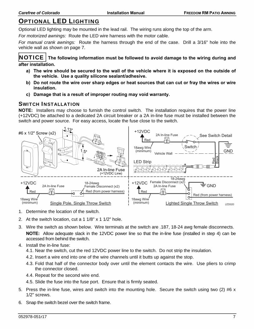
SWITCH INSTALLATION NOTE: Installers may choose to furnish the control switch. The installation requires that the power line (+12VDC) be attached to a dedicated 2A circuit breaker or a 2A in-line fuse must be installed between the switch and power source. For easy access, locate the fuse close to the switch.
1. Determine the location of the switch.
2. At the switch location, cut a 1 1/8" x 1 1/2" hole.
3. Wire the switch as shown below. Wire terminals at the switch are .187, 18-24 awg female disconnects.
NOTE: Allow adequate slack in the 12VDC power line so that the in-line fuse (installed in step 4) can be accessed from behind the switch.
4. Install the in-line fuse: 4.1. Near the switch, cut the red 12VDC power line to the switch. Do not strip the insulation.
4.2. Insert a wire end into one of the wire channels until it butts up against the stop.
4.3. Fold that half of the connector body over until the element contacts the wire. Use pliers to crimp the connector closed.
4.4. Repeat for the second wire end.
4.5. Slide the fuse into the fuse port. Ensure that is firmly seated.
5. Press the in-line fuse, wires and switch into the mounting hole. Secure the switch using two (2) #6 x 1/2" screws.
6. Snap the switch bezel over the switch frame.
LED020
LED Strip
Vehicle Wall
Red
+12VDC
GNDSwitch18awg Wire
(minimum)
Red
Bla
ck
2A In-line Fuse See Switch Detail
ON
OFF
2A In-line Fuse(+12VDC Line)
Red
+12VDC
Single Pole, Single Throw Switch18awg Wire
(minimum)
Red (from power harness)
18-24awgFemale Disconnect (x2)2A In-line Fuse GND
Red
+12VDC
Lighted Single Throw Switch18awg Wire
(minimum)
Red (from power harness)
2A In-line Fuse
18-24awgFemale Disconnect (x2)
1.13"
1.5"
#6 x 1/2" Screw (x2)
Carefree of Colorado Installation Manual FREEDOM RM PATIO AWNING
8 052978-051r17
PITCH ADJUSTMENT The awning opens and closes with a steep pitch. On low profile vans, the leading edge of the awning may hit the top of the sliding door if the door is open while extending or retracting the awning. To prevent this, the lower limit of the pitch can be adjusted upwards.
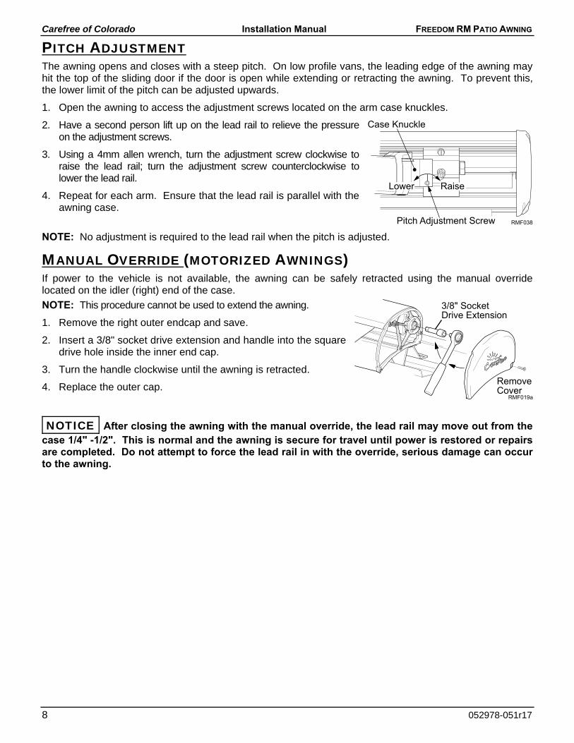
1. Open the awning to access the adjustment screws located on the arm case knuckles.
2. Have a second person lift up on the lead rail to relieve the pressure on the adjustment screws.
3. Using a 4mm allen wrench, turn the adjustment screw clockwise to raise the lead rail; turn the adjustment screw counterclockwise to lower the lead rail.
4. Repeat for each arm. Ensure that the lead rail is parallel with the awning case.
NOTE: No adjustment is required to the lead rail when the pitch is adjusted.
MANUAL OVERRIDE (MOTORIZED AWNINGS) If power to the vehicle is not available, the awning can be safely retracted using the manual override located on the idler (right) end of the case.
NOTE: This procedure cannot be used to extend the awning.
1. Remove the right outer endcap and save.
2. Insert a 3/8" socket drive extension and handle into the square drive hole inside the inner end cap.
3. Turn the handle clockwise until the awning is retracted.
4. Replace the outer cap.
NOTICE After closing the awning with the manual override, the lead rail may move out from the case 1/4" -1/2". This is normal and the awning is secure for travel until power is restored or repairs are completed. Do not attempt to force the lead rail in with the override, serious damage can occur to the awning.
RMF019a
3/8" SocketDrive Extension
RemoveCover
RMF038
Case Knuckle
Lower Raise
Pitch Adjustment Screw
Carefree of Colorado Installation Manual FREEDOM RM PATIO AWNING
052978-051r17 9
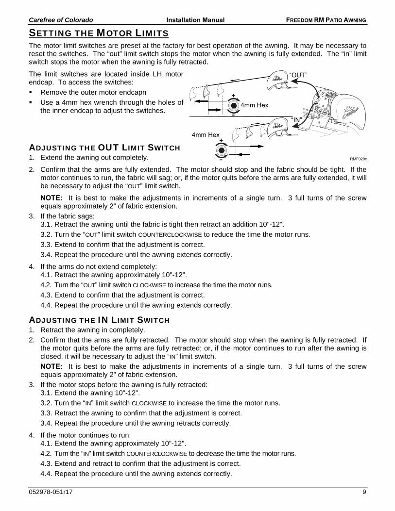
SETTING THE MOTOR LIMITS The motor limit switches are preset at the factory for best operation of the awning. It may be necessary to reset the switches. The “out” limit switch stops the motor when the awning is fully extended. The “in” limit switch stops the motor when the awning is fully retracted.
The limit switches are located inside LH motor endcap. To access the switches:
Remove the outer motor endcapn
Use a 4mm hex wrench through the holes of the inner endcap to adjust the switches.
ADJUSTING THE OUT LIMIT SWITCH 1. Extend the awning out completely.
2. Confirm that the arms are fully extended. The motor should stop and the fabric should be tight. If the motor continues to run, the fabric will sag; or, if the motor quits before the arms are fully extended, it will be necessary to adjust the “OUT” limit switch.
NOTE: It is best to make the adjustments in increments of a single turn. 3 full turns of the screw equals approximately 2” of fabric extension.
3. If the fabric sags: 3.1. Retract the awning until the fabric is tight then retract an addition 10"-12".
3.2. Turn the “OUT” limit switch COUNTERCLOCKWISE to reduce the time the motor runs.
3.3. Extend to confirm that the adjustment is correct.
3.4. Repeat the procedure until the awning extends correctly.
4. If the arms do not extend completely: 4.1. Retract the awning approximately 10"-12".
4.2. Turn the “OUT” limit switch CLOCKWISE to increase the time the motor runs.
4.3. Extend to confirm that the adjustment is correct.
4.4. Repeat the procedure until the awning extends correctly.
ADJUSTING THE IN LIMIT SWITCH 1. Retract the awning in completely.
2. Confirm that the arms are fully retracted. The motor should stop when the awning is fully retracted. If the motor quits before the arms are fully retracted; or, if the motor continues to run after the awning is closed, it will be necessary to adjust the “IN” limit switch.
NOTE: It is best to make the adjustments in increments of a single turn. 3 full turns of the screw equals approximately 2” of fabric extension.
3. If the motor stops before the awning is fully retracted: 3.1. Extend the awning 10"-12".
3.2. Turn the “IN” limit switch CLOCKWISE to increase the time the motor runs.
3.3. Retract the awning to confirm that the adjustment is correct.
3.4. Repeat the procedure until the awning retracts correctly.
4. If the motor continues to run: 4.1. Extend the awning approximately 10"-12".
4.2. Turn the “IN” limit switch COUNTERCLOCKWISE to decrease the time the motor runs.
4.3. Extend and retract to confirm that the adjustment is correct.
4.4. Repeat the procedure until the awning extends correctly.
RMF020c
“OUT”
“IN”
4mm Hex
4mm Hex