Embed Size (px)
Citation preview

Owing to initial bedding down of the clutch plate inserts. the clutch control may require adjustment after the first few hundred Krns with a new machine. This point should therefore be examined soon after delivery and adjustment made if necessary. Initially, excessive play fn the cable can be taken up through midway adjuster and the adjuster a t the handle bar end.
NOTE: The clutch adjuster ball and clutch rod may require cleaning and greasing around 6000 rniles/10000Krns of run. To do this, loosen and carefully remove the clutch adjuster from its position, taking care not to drop it into the gear box outer cover.
Start the engine and tilt the motorcycle towards the gear box side. so that the clutch rod can be removed. Wash thoroughly. the clutch rod and adjuster and look for chipped or worn clutch rod ends and free rotation of the clutch adjuster ball.
Smear multipurpose grease on the clutch rod and reassemble into the mainshaft. Smear grease on the clutch adjuster ball and carefully reassemble in its location. Adjust the adjuster to ensure free play is maintained on handle bar end and tighten lock nut.
15. Ntting the Alternator
The dternator consists of two parts. the stator and the rotor. The stator is mounted on to the primary chaincase inner by three studs and nuts.
The rotor, which contains the permanent magnet, is mounted on the end of the drive shaft and is located by a key and secured by a special nut and spring washer. The designed radiai air gap between the rotor and the poles of the stator is 0.25mm ( 0.010") and care must be taken when refitting to see that it is not less than O.15mm (O.OOG"] a t any point.
SINGLE PHASE ALTERNATOR
he stam - a f~xed ring wrth c4ib
carrying powec to the sry via the rectlfler

Fit the rotor first, making sure that it is located concentricaUy on the end of the drive shaft. Attention must be given to the proper seating of the key. Finally secure the rotor with the appropriate washer and nut.
Having fitted the rotor, the stator may then be fitted on to the chaincase inner with the coil connections facing outwards. Replace the shake proof washers and the nuts on the studs and tighten gently. Insert six strips [preferably non magnetic material) O.15rnrn (0.006") thick and 25.4mm [l") wide. Check whether the s&ips are free in position. If one or more of the strips are not free, gently tap stator [at the opposite end) to centralise the same such that all the strips become free. Tighten the stator nuts and ensure the strips move freely. Gently crank engine. recheck the strips are free. Repeat this process at 3 or 4 places and then withdraw the strips.
16. Function of Breather
The efficient operation of the breather is of paramount importance to the performance of the engine because it acts as a non-return valve between the crank case and outside atmosphere. causing a partial vacuum in the crankcase and rocker boxes which prevents the passage of oil into the cylinder. If the breather is not acting efficiently it may cause pressure in the crankcase instead of partial vacuum, giving rise to smoking or oiling of the plug.
17. Gear Box
The gears, ratchet mechanism etc, of the gear box can also be serviced without dismantling the engine from the frame.
Please refer page 33 for dismantling the gear box.

SERVICE OPERATIONS
ENGINE REMOVED FROM FIPAlME
l. Removal of the Engine from the Frame
k Disconnect alternator leads, B. Disconnect the spark plug cap. Suppressor cap C. Turn off petrol tap and disconnect the fuel pipe. D. Remove carburettor assy. along with throttle cable. E. Remove the air filter assy., F. Remove the exhaust pipe and Silencer, G. Disconnect the engine steady bolt, H. Remove the rear chain, I. Remove the footrest &.H.), J. Support the engine on a suitable box or wood block, K. Remove the centre stand and the stand stop. L.Remove the kont engine plates and the small bolt fixing the stand spring bracket and fixes rear mudguared, M. Remove the stud securing the rear engine plate to the frame, N. Slide out the engine.
2. Removal of the Gearbox
Remove the primary chaincase outer, clutch assembly, stator and rotor, engine sprocket and clutch sprocket. Remove the clutch centre and chain case inner.
Remove four 3/8" nuts and the gearbox can then be withdrawn from the engine.
3. Dismantling the Crankcase
Drain the oil tank by removing the feed and return flter assembly plugs located in the crank- case bottom.
Having removed the engine kom the frame dismantle the cylinder head, barrel, piston, timing gear, etc., as described in the chapter "Decarbonising".
Remove the nuts on the driving side of the engine kom four fixed studs at the rear of the crankcase.
Remove six studs passing through the crankcase by undoing nuts.
The two halves of the crankcase can then be separated.
The driving side outer race of bearings remain in the driving side half of the crankcase.
The driving side bearing inner race and the inner distance piece will remain on the engine shaft. (Crank shaft]
The flywheel assembly may be removed from the driving side of the crankcase. 9 2
4. Removal and Reassembly of main bearings 1. Clean the crank case thoroughly as any trace of oil in the crankcase will burn and
discolour the bearing race while heating the crank case.
2. Heat the crankcase in an oven or apply the naked flame of a blow lamp on the circumferential area of the bearing boss and not directly on the bearing race. When the crankcase gets heated up fairly, tap the crankcase on a wooden block [with bearing race facing downwards) gently so that it will drop down due to the expansion of the bearing boss.
3. Remove the circlip from the driving side crankcase and reheat to remove the ball bearing.

Inspect the bearings before assembly. The bearing should spin smoothly. Rotated dry, it may appear to be slightly noisy but there should be no signs of corrosion. nor must there be any appreciable radial slachess. The outer race of the roller bearing must be preferably smooth and bright with no evidence of cracks or pitting. The individual rollers must show no signs of wear and should rotate smoothly in the cage. It is recommended to replace with new bearings. once they are removed from the crankcase.
Reheat the crank cases to reassemble the bearings in the crankcase. Assemble the ball bearing in the D/S. Crankcase after fitting the circlip. Locate the other circlip. distance tubes outer and inner and then assemble the roller bearing outer race.
Ensure that the bearings are seated properly in the crank case and the outer roller race is flush with the crank case.
TIMING SIDE ROLLER BEARING ASSEMBLY DRIVING SIDE BEARING ASSEMBLY
I I
5. Replacement of the Cam Idler Spindles
When wear is noticed or step formation seen on the spindle. it should be replaced. To remove the cam spindle, heat the crankcase and tap the spindles out from inside.
To remove the idler pinion spindles. heat the crankcases as before. hold the spindles in a vice and tap the crankcase lightly with a nylon/wooden hammer.
To replace the cam spindles, locate the spindles in respective holes in the timing side crankcase and drive the spindles in home with a small hammer (1/2 lb.) and a drift. Make sure that the spindles are upright and parallel to each other.
6. Connecting Rod .. ,
CONNECTING ROD Wear in the hardened steel big end bush yhl be shown by a formation of a ridge round the centre of the bearing surface corresponding with the oil groove in the white metal floating bush. If this wear is excessive the connecting rod should be replaced. .
Excessive wear on the small end of the connecting rod can be easily seen. The Gudgeon Pin will show a rocking motion if wear is excessive.

7. Flywheel Assembly
The flywheel assembly consists of the crankshaft and the connecting rod.
To dismantle the crankshaft remove the set screws securing the crankpin nuts. Holding the crankshaft in a special jig. ('PED 2037) Remove the crankpin nuts.
Using PED 2037, wlth a pair of steel bars (about 1" X 3/8 X 9" long) placed across, between the fly wheel disc, press out the crankpin using a hand press.
The connecting rod can then be removed dong with floating bush.
Turn the crankshaft over in the jig and repeat with other side if necessary.
To remove the timing shaft. remove the set screw from the shaft nut and unscrew the nut. Drive the shaft out with a hammer and drift. To replace the ttming side shaft, reverse the above process, making sure that the key is a good At and that the nut F L Y W H ~ ASSEMBLY
is tightened securely by means of a box spanner with a 12" tommy bar.
The driving shaft has no nut but is secured by tightenfng the sprocket nut after the assembly of the engine. I t should be pressed In wlth a hand press or a hammer and drift. If the latter is used care must be taken not to damage the centre. It has a collar which butts against the flywheel disc.
To reassemble the crankshaft, press the crankpin into'the tim- ing side flywheel. making sure that the oil hole is in the correct position and the thrust washer is facing the right way. i.e. with Chamfer away from the fly- wheel.
Test the oil passages using an oil can to make sure that they are clear.
Assemble the floating bush over the crankpin.
Assemble the connecting rod over the floating bush and smear engine oil.
Place the other thrust washer over the crankpin, also with the Chamfer away from the fly- wheel.
Use a brass drift and hammer for pressing the D/S flywheel.
Locate the flywheel in the assembly jig, to ensure that the flywheels and shafts are In h e an replace the nuts, tighten securely and reflt the set screws. FLYWHEEL IN A a,
Test the 011 passages again to ensure that they are clear. (1 Lf the same crankpin has been put back, it will be neces- sary to drill out the old grub screw, in order to clean the oil passages after which a new grub screw must be F e d .
Mount the crankshaft between the centres of a lathe or on a pair of vee block and true upto .00lU on either side of the shafts.
If the readings for the two shafts are high on opposite sides, the error can be corrected by gently tapping either or both of the flywheels.
Lf the readings are high on the same side of the two shafts, it is probably due to dirt or foreign matter in the joints and the crankshaft should be dismantled again, carefully examined and cleaned and re-assembled.
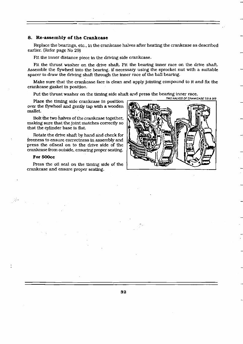
8. Re-assembly of the Crankcase
Replace the bearings, etc.. in the crankcase halves after heating the crankcase as described earlier. (Refer page No 29)
F'it the inner distance piece in the driving side crankcase.
F'it the thrust washer on the drive shaft. Fit the bearing inner race on the drive shaft. Assemble the flywheel into the bearing. if necessary using the sprocket nut with a suitable spacer to draw the driving shaft through the inner race of the ball bearing.
Make sure that the crankcase face is clean and apply jointing compound to it and Ax the crankcase gasket in position.
Put the thrust washer on the timing side shaft and press the bearing inner race.
Place the timing side crankcase in position over the flywheel and gently tap wfth a wooden mallet.
Bolt the two h e s of the crankcase together. making sure that the joint matches correctly so that the cylinder base is flat.
Rotate the drfve shaft by hand and check for freeness to ensure correctness in assembly and press the oilseal on to the drive side of the crankcase from outside, ensuring proper seating.
For MW)cc
Press the oil seal on the timing side of the crankcase and ensure proper seating.
TWO HALVES OF CRANKCASE TB 1 a5

GEAR BOX
NOTE: Before atempting to remove the internal parts. Please ensure that the clutch assy. has been dismantled alongwith F.D. sprocket
1. Removal of Gear box from engine This has already been described earlier
2. Dismantling the Gear box The gear box can be completely dismantled with the engine in the frame except for the removal of the inside operator and the bearings in the gear box case. Remove the Mck starter crank, the gear change lever and the neutral finder. Remove the top and bottom small inspection covers and disconnect the clutch cable, after loosening clutch adjuster. Remove four screws and the gear box outer cover can then be detached. Remove the foot control plate assembly and foot control short by taking off the two nuts securing i t Remove the main shaft bearing cover which is attached by two screws. GEAR BOX m OUTER COVER REMOVED
EAR - MAINSHAFT 1 ing spring eyelet by means of a long BEARING COVER
screwdriver to prevent it from rebound-
top gear and dog will come away with the mainshaft. l
CAUTION: Hold the Kick starter retum- ing spring eyelet by means of a long screwdriver to prevent it from rebound- ing [and causing damage) while the main shaft bearing cover screw is removed.
The main shaft can be drawn straight out, if the clutch has been removed. which. however, should be done before taking off the gear box inner cover. The top gear pinion and dog will come away with the mainshaft. The layshaft can then be removed and the second and third gears drawn off the frnal drive sleeve together with the op- erator fork.
MAINSHAFT N NOTE: To take out the main shaft sleeve, the final drive sprocket must be removed and this is preferably done before remov- ing the inner cover. 77U gear &X is bolred on ro the back of the crankace and ha^ founpcedr, \
whuh are foor-conmNLd. mrda pcucn~edncutralfinde~: M g e a n are in consraru 3. Removal of the Ball B e d g s i e sh , changes being cffecrcd by robust &g c lu t ch .
7hr inrernal gear ratios are 2.77: 1 (lsr Gear). 1.84: 1 (Zndgear) 1.36: 1 (3rd The mainshaft ball bearings can be gear) and I : I l ~ o p gear)
removed by using a stepped drift of 0.437 ( l l mm) & 1.171" (29.77,mm) in diameter f o ~ the bearing in the case and 0.812" (20.64 mm) & 0.515" (13.1 mm) in diameter for the bearing in the cover.
and this is done before remov- I I ing the inner cover. 77U gear &X is bolred on ro the back of the crankace and ha^ founpcedr, \
which are joor-conmNLd. mrdapcucn~edncutralfinde~: M g e a n are in consraru
When refitting the bearing stepped drifts of 2.3 1" (58.7mm) & 1.17 1" (29.7mm) diameter and ln.(25.4mm) in diameter, must be used for bearings in the case and cover respectively.
4. Gear Change Mechanism
If the two pins securing the gear change ratchet mechanism are slackened, the adjuster plate can be set in the desired position. In this position the movement of the gear lever, necessary to engage the ratchet teeth will be approximately the same In each direction.
If the plate is incorrectly adjusted, it may be found that, after moving top to third or from bottom to second gear, the outer ratchets will not engage the teeth on the inner ratchets correctly.

CHANGE GEAR MECHANISM
When fitting new parts, if it is found that the gears do not engage properly, ascertain whether a little more movement is required or whether there is too much movement so that the gear slips right through second or third gear into neutral. If more movement i s required, even after adjusting the adjuster plate then this can be - obtained by filing the 1 - Main sbft foot control stop plate 2. Main shafts~eew
very 'lightly at the 3.Mainshnftlowgempinion25T points of contact with the pegs on the ratchet 4. Mai" shaft swing gem21T& IBT
ring. 5. Gear operntor fork 6. Main shaft high gear pinion dog If too much
movement i s already 7- Main ~ h a f f highgearpinion 15T
present. a new foot B. M& shaft oil thrower innm control stop plate giving less movement must be fitted.
4.1 Gear box with Continental controls.
The procedure for dismantling the gear box with continental controls is the same as described earliar.
While dismantling the gear change mechanism care should be taken to disconnect the foot control lever from the gear shift shaft after loosening the hex bolt. The circlip provided on the gear shift shaft should also be removed prior to removing the inner cover.
Grease nipples are provided on the shift shaft and gear lever on the left side of the motorcycle for periodical greasing to ensure smooth operation of shift shaft and gear lever.
9. Lay shnft splined bush
10. Lay shnft low gear pinion 15T
1 I . Lay shaft second gem pinion 19T
12. Lay shaft third gear ptnion 22T
13. Lay shaft high gear and K/S wheel 25T
14. Lay shaft
GEXR BOX Wrrrt CONTlNENTAL CONTROLS
If excessive gear lever travel is noticed and gear engagement becomes difficult, the plastic bushes provided ~

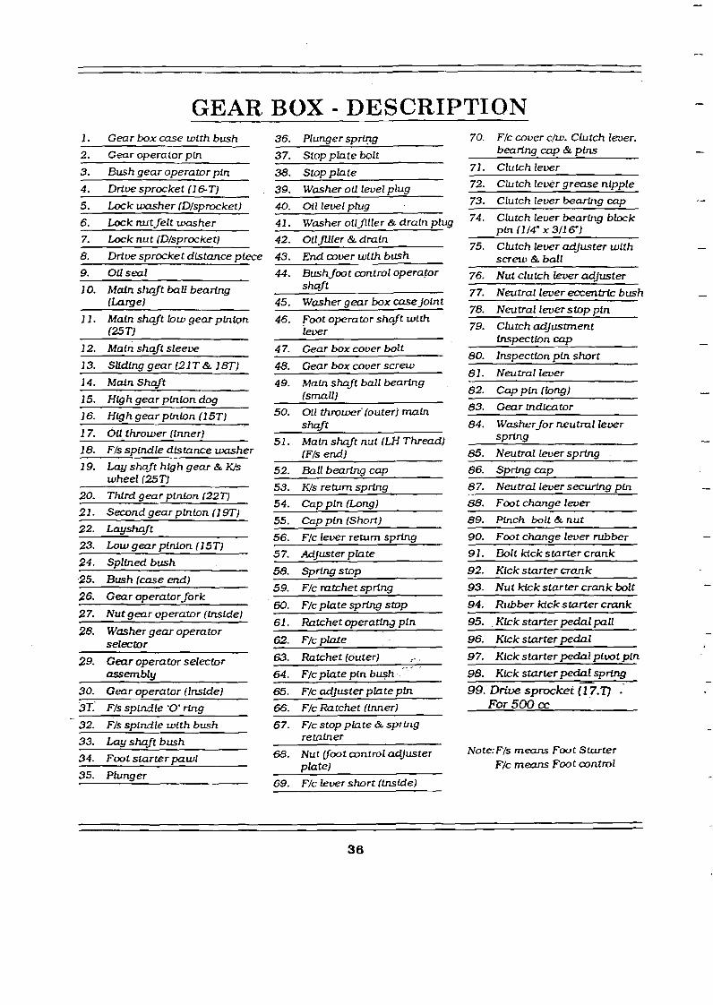
GEAR BOX - DESCRIPTION p~ --
36. Plunger spring
37. Stop pfate bolt
38. Stopplate
39. Washer oil level plug
70. Flc cover cm. Clutch lwer. b e a m c a ~ & pins
1. Gear box case with bush
2. Gear operator pln
3. Bush gear operator pin
4. Drive sprccket (1 6 T J
--
71. Clutch lever
72. Clutch lekr grease nlpple
73. Clutch Ieuer beczrhg car, 5. h k washer (D/s~rocket) 40. Ol l level ~ i u a 74. Clutch lever bearing b k k
pin 11l4" X 3/16"]
75. Clutch lever adjuster with screw & ba f l
- - -
6. Luck nut felt =her
7. Luck nut (Dlsprocket)
8. Drive sprocket distance ~ i e c e
--p -
41. Washer oilflller & drain plug
43. End wwr with bush
44. Bush foot wntrol opera.tor shaft
45. Washer gear box uzse Joint
46. Foot operator shqft with lever
4 7. Gear box cover bolt
76. Nut clutch lewr adjuster 10. Mdn shaft ball be&
(LameJ 77. Neutral lever eocentrk bush
78. Neutral lwer stop ~ f n 11. Maln shaft low gear phton
125 T)
12. Main shaft sleeve
79. Clutch adJustment tnspectlon cap
80. Inspection pLn short
81. Neutral lever
82. Cap pin (long) 83. Gear indicator
84. Washer for neutral lewr spring
13. Sliding gear l2 1 T & 1 L T )
14. Mdn Shaft
15. High gear p h b n 4 16. High gear phion (l 5T)
17. OU thrower (inner)
48. Gear box cover screw
49. Maln shaft ball bearing lsmalll
- - P P
50. 0 1 1 throwef(outer) m a h shaft
51. Main shaft nut (LH Thread) 18. Fls spindle distance washer (Fls end;
52. Ball bearing cap
53. Ws return spring
54. Cap pin (Lens)
85. Neutral lever sDrina 19. LPyshnft highgear& K/
wheel (25 TJ
20. Thlrd gear pinion (22T)
21. Second gear pinion (1 9T)
87. Neutral lever securLng pin
88. Foot change lever
55. Cap pin (Short)
56. Ffc lever return spring
5 7. AdJuster p fate
58. S~rino s t o ~
89. Pinch bolt&nut
90. Foot change lever rubber
91. Bolt kick starter crank
92. Kick starter crank
23. Low gear pinlon (15;)
24. Splined bush
25. Bush (case end) 93. Nut kick starter crank bolt
94. Rubber kick starter cmnk
59. F/c mtchet spring 26. Gear operatorfork
27. Nut near operator (LnsideJ 60. F/c plate S D ~ stop
61. Ratchet operating pin 95. Kick starter pedal pall
96. Kick starter pedal 28. Washer gear operator
selector 62. F/c plate
63. Ratchet (outer) c , , ,
64. Flc plate pin bush
97. Kick starter wdal ~ iuot Din 29. Geur operator selector assemblu
P
98. Kkk starter pedal sprfng
99. Driue sprocket (1 7.77 . For 500 cc
30. Gear operator Ilnstdel
- 3T.' F/s spindle '0' ring
32. F/s spindle with bush
a. Flc adJuster pfute pin
66. F/c Ratchet (inner)
67. F/cstopplate&spring retainer 33. Lctu shaft bush
Note: Fls means F m t Starter F/c means Fmt control
68. Nut root wntrol adjuster plate)
34. ~ o o t starter pawl
35. Plunger 69. F/c lever short (fnslde)

5. Re-assembling the Gear box
The procedure is the reverse of that given above for dismantling but the following points should be noted.
If the main shaft top gear pinion and dog have been removed, make sure that the dog is replaced the right way round or third and top gears can be engaged simultaneously.
Make sure that the trunnions on the operator fork engage with the slots in the lnside operator.
See that themin shaft is pushed right home. (It may be tight because of the felt washer inside the flnal drive shaft nut). \
The layshaft top gear and kickstarter pinion, should be assembled on the layshaft and the kickstarter shaft and Ratchet assembled on to it before fitting the end cover. Do not forget the washer on the layshaft between the kickstarter pinion and kickstarter shaft.
The joint between the gear b x and the imer cover should be made with shellac or any similar jointing compound.
Make sure that a11 parts are clean before commencing assembly. The gear box should be packed with soft grease (veedol '00' grease or equivalent) filed up to the correct level.
On no account must heavy yellow grease be used.
6. Adjustment of the Neutral Nnder
The neutral flnder is adjusted by means of an ercentric stopper secured to the front of the gear box cover by a b l t which limits the travel of the operating pedal. Slacken the bolt and turn the eccentric stopper until the correct movement of the pedal I s obtained.
NEUTRAL FINDER
7. Lubrication of the Gear box
Current machhes have the gear filler pIug at the top ol the bax and a level plug at the m. Remow bdh plugs and W, with the machine on leve@nmd until the ofl oxmxnces to flow from the leveI plug.
Check the lwel every 800 to 1,600 Km. wben the gear box is warm.
For initial fllling up of gear box VEEDOL '00' grease is recommended During routine maintenance, topping up may be done with SAE 50 oil.
The capacity is 700 grams (Approx.) of '00' grease mixed with SAE 50 grade oil to a thick consistency.

LUBRICATION SYSTEM
Lubrication system is by Dry Sump and effected by an automatic and positive double action oil pumps.
The oil tank is integral with the crankcase, for ensuring the full rate of oil circulation immediately when the engine is started and for rapid heating of the oil in cold weather. The capacity of the oil sump is 2.25 Ltrs. (SAE 50 grade). There are two piston trpe oil pumps running at 1 / 12 of engine speed positively driven by the worm gear on the timtng shaft.
The feed pump is at the rear of the timtng cover (Left side when viewed from the front) and pumps oil from the oil tank, through the oil filter to the big end through the ttming shaft. After lubrication of the big end bearings, the oil splashes and lubricates the cylinder barrel walls and drains to the bottom of the crank case.
The return pump (front side of the timing cover) draws the oil from the crank case through the drilled passage and passes through the rocker oil pipe and lubricates the rocker bearings and valve sprlng mechanism and flows down though the push rod tunnels into the timLng cover chest.
From here, the drained oil is pumped back to the oil tank though a hole ( W e d in the RH crankcase). by the two idler pinions. The return pump has a capacity of approximately double that of the feed pump, which ensures that oil does not accumulate in the crankcase. If allowed to accumuIate it will Iead to smoke - oil splash through breather pipe and starvation of oil to rocker arm bearings.
Both pumps are double acting. but two sides of feed pump are inter -connected, thereby giving an augmented and even supply to the big-end. Return pump is also inter-connected for effective scavenging from crank case.
Gauze strainers are provided for both feed and return filters from the crankcase to ensure oil is free from dirt and sludge.
Oil Filter: The oil filter has a special and important feature in design. In the case of clogged fllter or should it be neglected the oil pressure will lift the spring and cap off of its seat. thereby automatically by-passhg the fllter so that the big end bearings will not be deprived of lubrication. wen though the oil may be dirty.

OIL PUMP DIAGRAMS
FEED PUMP
PORTS IN THE TIMING COVER
Y - Suction from Oil tank
X -Delivery to big end.
Position 1: The plunger A is drawn out of the feed pump disc C, by the peg B in the spindle D, due to its rotation.
The suction port T in the pump disc aligns with the suction port Y in the timing cover and oil from the tank is drawn into the pump disc as the plunger is drawn out. 1 Simultaneously. the through hole W h the disc registers with the dellvery port X ih the timing cover.
The outward movement of the plunger forces the accumulated oil in the annular spdce in the timing cover to be delivered to the big end bearings through the oil filter element.
FEED PUMP
PORT3 IN FEED PUMP DISC
T - Suction port
R - Delivery port
W, Z - Through holes
Position 2:- As the pump spindle rotates further the plunger A is pushed into the pump disc C.
The delivery port R in the pump disc registers with the delivery port X in the timing cover. The oil in the pump disc i s forced out through these ports, by the plunger for supply to the oil filter element and to the big ends.
Simultaneously the through hole Z , In the pu.15~ disc registers with the suction port Y in the timing cover and draws oil from the tank, into the annular space in the timing cover, due to inward movement of the plunger into the disc.

RETURN PUMP
PORTS IN THE TIMING COVER
Y - Suction from Crankcase
X - Delivery to Rockery
Position 1:- The plunger A' is drawn out of the return pump disc C' by the peg B on the spindle D. due to its rotation.
The suction port T in the pump disc regis- ters with the suction port Y in the timing cover and oil from the crank case is drawn into the pump disc as the plunger is drawn out.
Simultaneously, the through hole W in the disc registers with the delivery port X' in the timing cover.
The movement of the plunger forces the ac- cumulated ofl in the annular space in the timing cover to be delivered to the cylinder head.
.RETURN PUMP
PORTS IN THE RETURN PUMP DISC
T - Suction Port
R' - Delivery Port
W 2' - Through holes - Positlon 2:- As the pump spindle rotates fur- ther the plunger A' is pushed into the pump disc C' - The delivery port R' in the pump disc regis- ters with the delivery port X in the timing cover. The oil in the pump disc is forced out - through these ports, by the plunger. for sup- ply to the cylinder head.
Simultaneously the through hole 2' in the +
pump disc registers with the suction port Y in *ertiming cover and draws oil from the cratlk case chamber into the annular space - in the timing cover due to inward movement of the plunger into the disc.

FRAME REAR SUSPENSION
1. Description of Frame
The frame is buiIt of special cold drawn welded steel tubing incorporating reinforcements wherever necessary, for extra strength.
The swinging arm unit forms the chainstay and is fitted with rubber bonded 'silent-bloc' bushes. The swinging arm unit is secured to the main frame by a long bolt passing through the pivot lugs.
2. Removal of Rear Spring Box Unit/ Servicing Rear Spring Box
Remove the top pivot pin nut, drive out the pivot REAR SPRING BOX REMOVAL
pin, then hinge the suspension unit back on the lower pivot pin. After removing the lower nut, the unit may be pushed off the pivot pin welded to the fork end. It is a sealed unit and the internal mechanism cannot be serviced. Outer dust cover can be removed using spe- cial tool PED- 2039 for cleaning coil spring.
3. Removal of Swinging Arm Chain Stay
Remove the rear wheel, chain. rear sprocket and .brake cover plate assembly kom the swinging arm chaln stay. Remove one of the pivot nuts and pull the pivot pin kom the other end. The chainstay can then be pulled out of the frame.
The life of the rubber bonded 'silent-bloc bushes' is very high. But if it is necessary to replace the bushes. the inner sleeves will have to be pressed out first on a press. The rubber can then be taken away fiom the outer sleeves by pliers. The outer sIeeves 'a be driven out by means of a hammer and a suitable drift.
Replace the rubber bonded bushes in the swinging arm. using a suitable drift, press one bush from one end of the pivot bearing tube under a press, until the metal outer sleeve is flush with the end face of the pivot bearing tube. While pressing, it must be ensured that pressure is exerted only on the outer sleeve and not on the inner sle&e of the bush, as axial pressure on the.inner sleeve would destroy the bonding of the rubber to the metal sleeves. Similarly press the second bush from the other side of the pivot bearing tube until the metal outer sleeve is flush with its end face.
While assembling, the swinging arm fitted with rubber bonded 'silent-bloc' bushes, to the frame, the pivot nuts should be fully tightened only with the swinging arm positioned in the mid-stroke of the spring boxes, i.e.. when the centre distance between the spring box top mounting hole in the frame and the bottom mounting pin on the swinging arm is 9.75". This is recommended so that, the rubber bush will be subjected to minimum angular movement in either hec t ion kom the mid stroke.
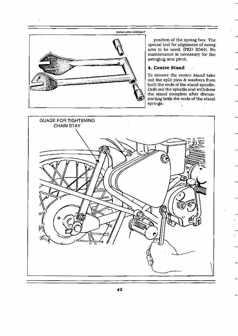
SWING ARMASSEMBLY
position of the spring box. The special tool for alignment of swing arm to be used. (PED 2044). No maintenance is necessary for the swinging arm pivot.
4. Centre Stand 1
To remove the centre stand take out the split pins & washers from both the ends of the stand spindle. Drift out the spindle and withdraw the stand complete after discon- necting both the ends of the stand springs.

FRONT FORK (Hydraulically damped)
1. Description
The telescopic fork consists of two legs each of which comprises a main tube of alloy steel tubing which is screwed into the Casquette fork head a t the upper end and securely clamped to the fork crown. Fitted over the lower end of the main tube is the bottom tube made of high strength aluminium alloy with an integral lug which carries the wheel spindle. Fitted on & lower end of the main tube IS a steel bush \ v W 1s a close fit in the bore of the bottom tube, The !@?er end of the bottom tube carries a cast iron bush which is a close fit over the outside diameter of the main tube. These bushes are not being fitted on to the latest Front Fork As-
semblies. The bush is secured to the bottom tube by means of a threaded housing which contains two oil seals. A stud known as the 'spring stud' is fitted in the iower end of the bottom tube and a valve port is secured to the lower end of the main tube. As the fork operates oil is forced between the spring stud and the bore of the valve port forming a hydraulic damping system. A compression spring is fitted inside the main tube between the upper end of the spring stud and the upper end of the main tube. The lower end of the ri:ain tube and upper end of the bottom tube are protected by a cover secured to the fork crown.
2. Operation of the Fork
INTERNAL HEXAGON
RUBBER RING
FORK CROWN
COVER TUBE
VAIAVE PORT
- The fork provides a range of movement of 6" from the fully extended to the fully compressed position. The movement is controlled by the
- compression spring and by the hydraulic d a m p ingsystem. The hydraulic damping is light on the bump stroke and heavier on the rebound stroke, thus damping out a y tendency to pitching or oscillation without interfering unduly with the free movement of the fork when the wheel encounters an obstacle o r a pot hole.
-

The fork is filled with a light oil (S.A.E. 30) to a point above the lower end of the spring so that the damper chamber 'B' is always kept full of oil. Upward movement of the wheel spindle forces oil from the lower chamber 'A' through the anndar space between the spring stud and the bore of the main tube valve port into the damper chamber 'B'. During this stroke the pressure on the underside of the valve plate causes this to lift so that oil can also pass from 'A' to 'B' through the eight holes in the valve body. Since, however, the diameter of chamber 'B' Is less than that of chamber 'A' there Is no room in 'B' to receive all the oil which must be displaced from 'A' as the fork operates. The surplus oil passes through the cross hole in the spring stud and up the centre hole in the stud, spilling out through the nut which secures the upper end of the spring stud to the guide at the lower end of the fork spring.
On the rebound stroke, the oil in the damper chamber 'B' Is forced through the anndar space between the spring stud and the bore of the main tube valve port. During this stroke pressure in chamber 'B' closes the .two disc valves at the upper and lower ends of the chamber so that the only path through which the oil can escape is the annular space between the spring stud and the port. Damping on the rebound stroke is therefore heavier than on the bump stroke. At the extreme end of either pump or rebound stroke a small taper portion on the spring stud enters the bore of the valve port, thus restricting the anndar space and increasing the amount of damping. At the extreme end of the bump stroke the larger diameter taper on the oil control collar enters the main counterbore of the valve port thus forming a hydraulic cushion to prevent metal to metal contact.
3. Djsmantling the Fork
Place the machine on the centre stand. disconnect the front brake control cable & speedometer connection and remove the front wheel and mudguard complete with stays. Unscrew the bottom spring. stud nut which will allow oil to run out of the fork down to the level of the cross hole in the spring stud. Now knock the spring stud upwards into the fork with a soff mallet. thus allowing the remainder of the oil to escape. Pull the fork bottom tube down as far as possible, thus exposing the oil seal housing. In the latest version the oil seal housing is eliminated and the oilseals are provided as an integral part of bottom tubes. Hence by pulling the bottom tube downwards the same can be removed from the forkmain tubes. [For old type front forks: Unscrew this housing by means of a spanner on the flats with which it is provided. The bottom tube can now be withdrawn CI
leaving the bottom tube bush, oil seal housing and oil,s%al in pc
MAIN W E E SPANNER PED2026
0
lmpletely from the main tube sition on the main tube.]
Now unscrew the main tube valve port using special tool PED 2026. The spring stud and spring can now be withdrawn from the lower end of the main tube.
NOTE: In the latest version the oilseal housing and steel bush has been eliminated on introduction of integral oil seals in the bottom tubes;
The steel main tube bush can now be tapped off the lower end of the tube, if necessary using the bottom tube bush for this purpose. Before doing this, however, it is advisable to mark the position of the bush with a pencil so as to ensure re-assembling it in the same position on the main tube. The reason for this is that these bushes are ground to size, after fitting on to the tubes, so as to ensure concentrictly. After removal of the main tube bush,

bottom tube bush and oil seal housing, the main tube can be removed using tool PED 2036ST. Before attempting to loosen the main tubes ensure that the 2 pinch bolts on the fork crown bottom has been sdcient ly loosened to allow the main tubes to rotate.
4. spring
The free length of the spring is 20 1/2". The spxing should be replaced if it has closed by more than 1 inch.
When refitting the oil seal, or fitting a new one, great care must be exercised not to damage the synthetic rubber Lip which forms the actual seal.
NOTE: (Only for Old ?Lpe Forks) If the oil seal housing has been removed from the upper end of the main tube and is refitted from this end, a special nose piece must be fitted over the threaded end of the tube to prevent damage to the ofl seal.
The spring stud is a tight fit in the hole at the lower end of the bottom &be. Once the stud has been located in the hole, push the bottom tube up sharply against the spring until two or three threads on the stud project beneath the end of the bottom tube. Now fit the nut and washer and pull the stud into position by tightening the nut. If necessary fit the nut first without the washer until suf.8cient thread is projecting to enable the washer to be fitted.
6. Removal of Complete fork Assembly
The fork complete with front wheel and mudguard can be removed from the machine, if necessary, by adopting the following procedure. The leads to the lighting switch and ammeter should be disconnected at their lower ends or by means of the plug and socket connectors when these are provided.
Disconnect the speedometer drive from the speedometer head.
Remove the two plug screws and loosen the steering head clip bolt and the two fork crown clamp bolts.
Unscrew the fork main tubes from the head lamp casing and the steering stem locknut from the top of the steering stem, turning each tube and the nut a turn or two at a time. When the nut has been removed from the steering stem and the main mbes have been completely unscrewed from the head lamp casing, the complete fork and wheel with steerlng stem can be removed.
7. Lubrication
The lubrication of the fork internal parts is effected by the oil whlch forms the hydraulic damping medium. All that is necessary is to keep smcient ofl in the fork to ensure that the top end of the bottom spring stud is never uncovered even in the full rebound position. The level of oil in the fork can be gauged by removing the top plug screw and inserting a long rod about 3/8" diameter. Lf slightly tilted this will wedge agatnst the nut at the upper end of the bottom spring stud.If the oil is above the spring stud, it will leave a trace on the long rod. which can be seen on removal. This trace of ofl implies that oil level is correct. If the fork is empty to start with, the quantity required is approximately 2 0 0 d in each leg. Recommended grade of oil is hydraulic oil or SAE 10 W 30.

8. Steering Head Races The steering head races are the same at the top and bottom of the head Iug. They are easily
removed by knocking them out with a hammer and drift and new races can be fitted either by a press or by means of a'harnrner and wooden drift The steering head bearing consists of two deep groove thrust races each containing nineteen 1/4" diameter balls. The bearing is adjusted by tightening the steering stem l o c h u t after loosening the ball head clip screw and both the fork crown clamp bolts. The head should be adjustedso that, when the front wheel is lifted clear of the ground, a light tap on the handlebar will cause the steering to swing to full lock in either direction, while at the same time there should be only the slight trace of pIay in the bearings.
The play can be felt by keeping a f iger across the head races just below the ball head on the top ball race. Do not forget to tighten the ball head clip screw and fork crown clamp bolts. Before tightening the latter make sure that the mver tubes are located centrally round the main tubes so that the bottom tube does not rub inside the mver tube. A pair of split bushes, as shown in f i e is useful to ensure centralisation of the cover tubes.
ADJUSTMENT W HEAD BAU-RACE
I STEM LOC
FRONT FORK CROWN CLIP BOLT
SEQUENCE FOR ADJUSTMENT
1. Loosen the Head lamp &sing clip bolt by using an AlIen key (Size - 5mm)
2. Loosen the front fork c r o h clip bolts (2 Nos.) 3. Then screw down the steeringstem lock nut by
1 3 -thread to ;r thread initially and check the play 2 once again. If necessary further tightening can be done.
Note: Over tightening of this Steering stern lock nut will result in vehicle drag.
9. Lubrication-Steering Head
The steering head races and stand pivot bearing should be well greased on assembIy. No nipples are provided for the steering head as experience has shown that the provision of nipples a t this point muses trouble through chafing and cutting of control and lighting mbl&. If the steering head bearings are well packed with grease initially they will last for several years or many thousands of kilometres.

WHEELS
FRONT WHEEL
1. Removal from Fork
To remove the front wheel from the fork place the machine on the centre stand with s a c i e n t packing beneath the stand to lift the front wheel clear off the gro~md whenvehicle is tilted back. Slacken the brake cable adjustment and disconnect the cable from the handlebar lever and from the operation cam lever on the hub.
Disconnect speedometer driving cable. Unscrew the four nuts securing the fork Lug caps and allow the wheel to drop forward out of the front fork. Make sure that the machine stands securely on the rear wheel and centre stand - if necessary place a weight on the dual seat or'a strut beneath the front end of engine near Frame down tube to ensure this.
2. Dismantling
Lock the brake 'on', by applying the front brake, and unscrew the cover plate nut. (For Front brake with twin leading shoes loesen the lock nuts on the link rod and turn link rod so that both brake shoes become free and are not in contact with the brake drum) The cover plate assembly can then be withdrawn from the brake drum.
The brake shoes can be removed after detaching the return springs. Brake linings are supplied in pairs and are of 'Bonded' type hence linings cannot be separated and refixed with new M g s .
To remove the operating cam unscrew the nut. which secures the operating lever to the splines on the cam. A sharp tap on the end of the cam spindle will now free the lever, after which the cam can be withdrawn from its housing. The brake shoe pivot pin can be removed after unscrewing the nut which secures it to the cover plate.
To remove the hub spindle and bearmgs, having h t removed the brake cover plate, unscrew the retaining nut by holding the spindle on a benchvice with soft jaws. Remove speedo drive assembly and the felt washer from the otherside of the hub. Remove the felt washer and the distance washer from the brake drum side and hit one end of the spindle with a brass or plastic mallet, thus driving it out of the hub, bringing one bearing with it and leaving the other in position in the hub. Drive the bearing off the spindle and insert the latter once more in the hub through the end from which it was removed. Now drive the spindle through the hub, the other way, which will bring out the other bearing.
3. Fitting Limits for Bearings
The fit of the bearings in the hub barrel is impo-t. The bearings are locked on the spindle between shoulders and the distance pieces, which in turn are held by the nuts on the spindle. In order to prevent endways pre-loading of the bearings, it is essential that there is a small clearance between the inner edge of the outer race of the bearing and the back of the races in either end of the barrel. To prevent any possibility of sideways movement of the hub barrel on the bearing$ is therefore necessary for the bearings to be a tight £it in the barrel, but this fit must not be so tight as to close down the outer race of the bearing and thus overload the ball race in the bearing

FRONT WHEEL AND HUB ASSEMBLY - SINGLE LEAD
1. Front Wheel rim (WM 2-1 91 2. Front Wheel spokes (outer] 3. Front Wheel spokes nipples 4. Front hub assembly (7" dia) 5. Front hub journal bearing (SKF 6203) 6. Front hub spindle 7 . Front hub felt retainer 8. Front hub felt washer ( d m side) 9. Front hub coverplate distance collar 10. Front hub felt washer (speedo side) 1 1. Front hub felt washer retainer (speedo side) 12. Front hub speedo drive spacing collar 13. Speedo driue complete
14. Front brake shoe c / w lining S/L 15. Front brake shoe spring ( 7 d i 4 16. Front brake wuerplate (7 dia) S/L 17. Front brake shoe pin (7" dia) S/L l 8. Washfront brake shoe pin S/L 19. Nutfront brake shoe pin S/L 20. Front brake opemting m (7" dial S/L 21. Nutfront hub c o w plate 22. Front hub spindle rurt (speedo side) 23. Front brake operating cam lever (7" dia)(S/LJ 24. Waswfront brake operating cam lever (S/LJ 25. Nutfront brake operatug cam lever S/L
4. Re-assembly bp,
To refit the bearings in the hub. two hollow drifts (Special Tool No. PED 20 1 1) are requtred. -
One bearing is first fitted to one end of the spindle by means of t'le hollow drift. The spindle and bearing are then inserted into one end of the hub barrel, which is then supported on one of the holIaw drifts. The other bearing is then inserted over the upper end of the spindle and - driven home by means of the second hollow drift either under a press or by means of a hammer, which will thus drive both bearings into position simultaneously.
In order to make quite sure that there is clearance between the inner faces of the outer bearing races and the bottom of the recesses in the hub, fit the distance washers, cover plate. dust excluder and the nuts on the spindle. Tightening the nuts should not have any effect on the ease with which the spindle can be rotated.

FRONT WHEEL AND HUB ASSEMBLY - TWIN LEAD
26. F/B operating lever [short) T / L 34. Front Brake Cover Plate T / L
27. h n t brake lever long T/L 35. Front brake shoe pin T /L 28. Link Rod Ft Brake T /L 36. Washer Front brake shoe pin T/L 29. L / R d Trimion (RH Thread) T / L 37. Nut Front brake shoe pin T / L 30. L/Rod Trunion Nut IRH) T/L 38. h n t brake operating cam 3 1 . L / R d Tmnwn (M T / L IM;9 39. Washerfront brake operating cam 32. L / R d TmnwnNut(LH7 T /L 40. Nut_fiont brake operating cam. 33. Front brake shoes C / W lining T /L
If tightening the nuts makes the spindle hard to turn, the bearings are bottoming in the reces'ses in the hub barrel and the inner races are-not resting on the shoulder of the spindle. In this case, the bearing should be removed and a thin packing shim should be fitted between the inner race and the shoulder on the spindle.
Assemble the operating cam into cover plate after smearing grease, on the pivot pin and the cylindrical bearing surface of the operating cam. Fit the operating lever. on its splines in a position to suit the extent of wear on the linings and secure with the nut and washer. Note that the position of the operating lever may have to be corrected when adjusting the brake after refitting the wheel. The range of adjustment can be extended by moving this lever on to a different spline.
NOTE: Before replacing the felt washers which form the grease seals. pack all bearings with medium/lime soap or aluminium soap greaseskor multipurpose grease. The use of H.M.P. greases which have a soda soap base is not recommended, as these tend to be slightly corrosive if any dampness finds its way into the hubs.
Make sure that the inside of the brake drum is quite free from oil or grease, dampness. etc. When replacing the speedo drive. make sure that the dogs on the speedo driveare correctly engaged with the slots in the end of the hub barrel. Make sure that the speedo drive is correctly positioned, so that the speedo cable would not be too stretched or will not have any sharp bends- Replace the felt washers, distance collars. and brake cover plate and securely tighten the spindle nuts.

REAR WHEEL
1. Removal of wheel - quickly-detachable type
The rear wheel is quickly detachable without disturbing the sprocket. Place vehicle on centre stand. Remove the split pin and the castle nut securing the long spindle which is located on the sprocket side. Slide out the long spindle from the wheel and remove both the spacers from the RH side fork end. Tilt the vehicle and slide out the wheel from the chainstay. For assembly reverse the process but take care to engage the cush rubbers properly on the driving lugs.
2. Cush Drive Four rubber blocks are fitted in the pockets of centre hub and four radial vanes are formed
RE.ASSEM~LYOFC~SHDF)IV~ on the back of the rear sprocket/brake drum, thus transmitting both drivhg and braking torque and smoothening out harshness and irregularity in the former.
Ifthe cush drive rubbers are worn. and the amount of free movement measured at the tyre exceeds 1 /2" to 1 ", the rubbers should be replaced. The condition of the cush drive rubber in the rear wheel can be gauged by placing the'machine on the r&r stand, applying the re* brake and rotating the rear wheel.
The cush rubbers are Axed in the pockets of centre hub by means of buttons provided in the rubber blocks, thus the rubbers are prevented from falling down when wheel is removed or refitted.
3. Removal and re-assembly of rear wheel sprocket
Removal of sprocket is necessary only if replacement of sprocket or attention to brakes is required. Remove the wheel as described above. Remove the brake rod nut and disconnect the brake rod from the operating lever. Be sure to 'DISCONNECT" the stop light switch from the link. otherwise the switch will get damaged. Remove the securing bolts of the chainguard a t both front and rear ends and remove the chain guard. Disconnect the chain link. Remove the securing nuts from brake anchor and wheel spindle. Unwrap the chain from the rear sprocket Slide out the rear sprocket assembly from the chainstay.
For re-assembly proceed in the reverse order. Make sure that the inside of the brake drum is quite free from oil grease dampness etc. Ensure the chain lock clip is fitted in the right direction so that the closed end of the clip is towards the direction of motfon. The rear chain should be inspected for wear before assembly. It should be renewed when its length has increased by 1- 1/8" than a new chain. The rear ChaLn can be adjusted by slackening the wheel spindle nuts and brake anchor shoe pin nut and turning the notched cam plate.

REAR W E E L AND HUB ASSEMBLY
1.- 2. Rear wheel s ~ o k e s Idust couer s ide-oum
cover slde-Inner) I . Rear w h e e w 5. Centre hub with barrel 8.. Rear hub beartnu spacer msu, 7. Rear hub dust cover
9. Rear hldb barrrel 0 ring . . J O . a h u b f - 12.- 13. Rear hub swindle frond u-bba W . Rear hub smocket 38T
le \.-W / 7. Rear hub bearina (&g& 18. Dtqtance collar [dust cover inner W 19. Rear hub distance collar [dust cover ~uterstdel 20. Rear brake shoe c/w (fntna (bonde& -
22. Rear brake cover wlate df- 73. Rear brake wver 0- - 27, Washer rear br-e pin (-~(alnl
28. Shoe win nut rear br- 29. Rear brake o?ercrtlneuun W 31. R 7
brake o~eratt- 33. *ear b& 34. Rear brake returzlSgdaa 35. Rear brake- Cam Lever Asu - 7 - 39. ! ? a l c c t e r [m $0. LCJckn- - -

4. Dismantling the Rear Brake Shoes.
After separating the cover plate from sprocket assy, unscrew the brake shoe pivot pin lock nut and the operating lever n u t The assembly of brake shoes, return springs, pivot pin and operating cam can be removed fiom the cover plate by unscrewing the pivot pin and applying light blows with a hammer and drift on the end of the operating cam. The return spring can then be unhooked fiom the brake shoes.
Brake linings are supplied in pairs and are of bonded type hence ltntngs cannot be seperated and refked with new linings.
5. Removal of bearing fiom centre hub and re-aeeembly
The bearing fiom the centre hub can be removed by inserting a small rod of 6 mm dia. Insert the rod through the bearkg at one end and through the slit provided. a t the ends of the bearing distance tube. Hit the rod with a small mallet on radially opposite sides of the bearing. The other bearing also can be removed by hitting it from opposite side after the removal of grease seal.
To remove the hub spindle [short) and bearings from the brake drum, having already removed the brake cover plate assy., hit outer end of the spindle with a brass hammer or mallet thus driving it out of the bearing. Now the grease seal and the bearing from the brake drum can be removed one after the other.
The fit of the beatFngs In the hub barrel is important as in the case of Front wheel.
To fit the bearings in the hub. use the two hollow drifts proceed as follows. In order to make sure that there is clearance between the inner faces of the bearings and the bottom of the recess, first fit the sealed bearing at the cush drlve side of the centre hub so that the bearing will sit In the housing flush with the boss face. Then place the distance tube fiom other end and press the second bearing and also the grease seal. (small]
NOTE: Before replacing the bearings in the centre hub as well as sprocket brake drum. pack with medium/heavy lime soap or aluminium soap grease. The use of HMP grease which have soda soap base is not recommended as these tend to be slightly corrosive ifany dampness finds its way into the hub.
6. Re-assembly of brake shots
Make sure that the brake shoe pivot pin is really tight in the cover plate and smear grease in the grooves of the pivot pin and on the operating face of the cam. Also smear grease on the
OPERAnON OF A SINGLE LEAD SHOE - DRUM BRAkE I I
drum
OPERAnON OFA M N LULD SHOE- DFIUM BRAKE
cylindrical bearing surface of the operating cam. if this has been removed. Fit the operating lever on its splines in a position to suit the extent of wear on the linings and secure with the nut. ?he range of adjustment can be extended by moving the lever on to a different spltne.
Note that the bolt holes in the cover plate for locating the rear brake cam bush are slotted, to enable the brake shoe assy. to be centered in the drum. The brake cover plate assy with the shoes should be fitted over the spindle into the brake drum and the brake applied as hard as possible by means of the operating lever. This will centre the shoes in the d m . The brake cover plate assembly should then be removed and the screws should then be tightened fully and secured with the lock nuts. If the shoes are not correctly centred, the brake will be either ineffective or too fierce. depending on whether the trailing or leadtng shoe first makes contact with the drum. With the brake assy, correctly centered and screws securing the cam housing correctly tightened wear on both linfngs should be approx equal.
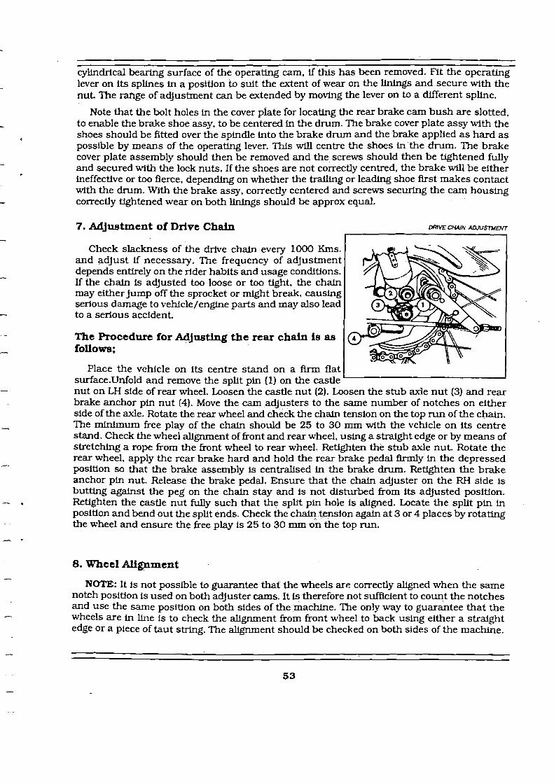
7. Adjustment of Drive Chain
Check slackness of the drive chain every 1000 Kms. and adjust if necessary. The frequency of adjustment depends entirely on the rider habits and usage conditions. If the chain is adjusted too loose or too tight, the chain may either jump off the sprocket or might break, causing serious damage to vehicle/engine parts and may also lead to a serious accident.
The Procedure for Adjusthg the rear chain is as foLlows;
Place the vehicle on its centre stand on a Arm flat
mVE CHAIN ADJUSTYENT
I I
surface.Unfold and remove the split pin (1) on the castle ' I
nut on LH side of rear wheel. Loosen the castle nut (2). Loosen the stub axle nut (3) and rear brake anchor pin nut (4). Move the cam adjusters to the same number of notches on either side of the axle. Rotate the rear wheel and check the chain tension on the top run of the chain. The minimum free play of the chain should be 25 to 30 mm wlth the vehicle on its centre stand. Check the wheel alignment of front and rear wheel, using a straight edge or by means of stretching a rope from the fkont wheel to rear wheel. Retighten the stub axle n u t Rotate the rear wheel, apply the rear brake hard and hold the rear brake pedal firmly in the depressed position so that the brake assembly is centralised in the brake drum. Retighten the brake anchor pin nut. Release the brake pedal. Ensure that the chain adjuster on the RH side is butting against the peg on the chain stay and is not disturbed from its adjusted position. Retighten the castle nut fully such that the split pin hole is aligned. Locate the split pin in position and bend out the split ends. Check the cha+ tension again a t 3 or 4 places by rotating the wheel and ensure the free play is 25 to 30 mm on the top run.
8. Wheel Alignment
NOTE: It is not possible to guarantee that the wheels are correctly a w e d when the same notch position is used on both adjuster cams. It is therefore not sufficient to count the notches and use the same position on both sides of the machine. The only way to guarantee that the wheels are in line is to check the alignment from front wheel to back using either a straight edge or a piece of taut string. The alignment should be checked on both sides of the machine.

It is usual to check the alignment of the wheels at a point about six inches above the ground. If the alignment is checked also towards the top of the wheels, it will be possible to ascertain whether or not the frame is twisted so 3s to cause one wheel to be leaning while the other is vertical. To do that it is always necessary to remove the mudguards and unless a straight edge cut away in its centre portion is available, it will be necessary also to remove the cylinder, tool boxes, batte~y etc., in order to allow straight edge or a piece of taut string to contact the front and rear tyres.
In the later models a punch mark is provided on both the chain adjusters. These punch marks can be used as reference marks and the chain adjusters must be moved by the same number of notches from this punch mark to ensure proper wheel alignment.
9. General
1. Wheel Rims
The rim fitted to the wheel is W M 2.19" pierced with 40 holes for Locating the spoke nipples.
2. Spokes
The spokes are of plain type 4 mm dia with 90 degree counter sunk heads, angle of bend 80 to 95 degree. Thread diameter is 4.4 mm X 0.7 pitch thread. Spoke lengths are 170 mm for the rear wheel and 165 mm for the front wheel.
3. Wheel Building and Truing
The spokes are laced in such a way that wheel must be b d t centrally in relation to the outer faces of the distance collars which At between the fork ends. The rim should be trued as accurately as possible, the maximum permissible run-out both sideways and radially being plus or minus 1 /32".
SPOKE LOALHNGS IN A WRE WHEEL
Dmctmn al r a m
Hub l

The key to correct lachg is the inside and outside spokes from the flange must slope down h the opposite direction as in the figure. The spokes are in opposite direction to the inner two spokes. In the group of four spokes laced, the inner spokes of each flange are sloping down in the opposite direction of the outer two spokes of the next grouping of four spokes and so on.
4. Lubrication
Front and rear wheel bearings are lubricated by packhg them with grease every 10.000 Kms. after dismantling the hub and requires no further attention.
Standard tyres are of size 3.25.19" for Front & 3.50.19" for Rear.
When removing the tyre always start close to the valve and see that the edge of the cover a t the other side of the wheel pushed down into the well.
If the correct method of fitting and removal of the tyre is adopted it will be found that the covers can be manipulated quite easily with the small tyre levers. The use of long levers and or excessive force is liable to damage the walls of the tyre. After inflation make sure that the tyre is fitting evenly all the way round the rim. A line moulded on the wall of the tyre indicates whether or not the tyre is correctly fitted.
Please refer the attached diagrams in Page No.59 for correct procedure for removal and refitting of tyres.