Embed Size (px)
Citation preview
Nuclear Safety
Nuclear Fuel Safety CriteriaTechnical Review
NUCLEAR ENERGY AGENCYORGANISATION FOR ECONOMIC CO-OPERATION AND DEVELOPMENT
ORGANISATION FOR ECONOMIC CO-OPERATION AND DEVELOPMENT
Pursuant to Article 1 of the Convention signed in Paris on 14th December 1960, and which came into force on30th September 1961, the Organisation for Economic Co-operation and Development (OECD) shall promote policiesdesigned:
− to achieve the highest sustainable economic growth and employment and a rising standard of living inMember countries, while maintaining financial stability, and thus to contribute to the development of theworld economy;
− to contribute to sound economic expansion in Member as well as non-member countries in the process ofeconomic development; and
− to contribute to the expansion of world trade on a multilateral, non-discriminatory basis in accordance withinternational obligations.
The original Member countries of the OECD are Austria, Belgium, Canada, Denmark, France, Germany, Greece,Iceland, Ireland, Italy, Luxembourg, the Netherlands, Norway, Portugal, Spain, Sweden, Switzerland, Turkey, the UnitedKingdom and the United States. The following countries became Members subsequently through accession at the datesindicated hereafter: Japan (28th April 1964), Finland (28th January 1969), Australia (7th June 1971), New Zealand (29thMay 1973), Mexico (18th May 1994), the Czech Republic (21st December 1995), Hungary (7th May 1996), Poland (22ndNovember 1996), Korea (12th December 1996) and the Slovak Republic (14 December 2000). The Commission of theEuropean Communities takes part in the work of the OECD (Article 13 of the OECD Convention).
NUCLEAR ENERGY AGENCY
The OECD Nuclear Energy Agency (NEA) was established on 1st February 1958 under the name of the OEECEuropean Nuclear Energy Agency. It received its present designation on 20th April 1972, when Japan became its firstnon-European full Member. NEA membership today consists of 27 OECD Member countries: Australia, Austria, Belgium,Canada, Czech Republic, Denmark, Finland, France, Germany, Greece, Hungary, Iceland, Ireland, Italy, Japan, Luxembourg,Mexico, the Netherlands, Norway, Portugal, Republic of Korea, Spain, Sweden, Switzerland, Turkey, the United Kingdomand the United States. The Commission of the European Communities also takes part in the work of the Agency.
The mission of the NEA is:
− to assist its Member countries in maintaining and further developing, through international co-operation, thescientific, technological and legal bases required for a safe, environmentally friendly and economical use ofnuclear energy for peaceful purposes, as well as
− to provide authoritative assessments and to forge common understandings on key issues, as input togovernment decisions on nuclear energy policy and to broader OECD policy analyses in areas such as energyand sustainable development.
Specific areas of competence of the NEA include safety and regulation of nuclear activities, radioactive wastemanagement, radiological protection, nuclear science, economic and technical analyses of the nuclear fuel cycle, nuclear lawand liability, and public information. The NEA Data Bank provides nuclear data and computer program services forparticipating countries.
In these and related tasks, the NEA works in close collaboration with the International Atomic Energy Agency inVienna, with which it has a Co-operation Agreement, as well as with other international organisations in the nuclear field.
© OECD 2001Permission to reproduce a portion of this work for non-commercial purposes or classroom use should be obtained through the Centre françaisd’exploitation du droit de copie (CCF), 20, rue des Grands-Augustins, 75006 Paris, France, Tel. (33-1) 44 07 47 70, Fax (33-1) 46 34 67 19,for every country except the United States. In the United States permission should be obtained through the Copyright Clearance Center,Customer Service, (508)750-8400, 222 Rosewood Drive, Danvers, MA 01923, USA, or CCC Online: http://www.copyright.com/. All otherapplications for permission to reproduce or translate all or part of this book should be made to OECD Publications, 2, rue André-Pascal,75775 Paris Cedex 16, France.
3
FOREWORD
The goal of nuclear reactor safety is to ensure that the operation of commercial nuclearpower plants does not contribute significantly to individual as well as societal health risks. Reactorsafety is thus primarily concerned with the prevention of radiation-related damage to the public fromthe operation of commercial nuclear reactors; safety limits are introduced to avoid fuel failures duringnormal operation, or to mitigate the consequences of reactor accidents in which substantial damage isdone to the reactor core.
In most countries dose rate limits are defined for a possible off-site radiological releasefollowing a reactor accident. Fuel safety criteria that relate to fuel damage are then specified to ensurethat these limits are not exceeded. Numerous criteria related to fuel damage are used in safetyanalyses. These criteria, however, may differ from country to country. Some criteria are used tominimise cladding degradation during normal operation, and some are used to maintain claddingintegrity during anticipated transients, thus avoiding fission product release. Others are used to limitfuel damage and ensure core coolability during design-basis accidents, or to limit the public risk fromlow probability severe accidents.
With the advent of advanced fuel and core designs, the adoption of more aggressiveoperational modes and the implementation of more accurate (best-estimate or statistical) design andanalysis methods, the question is being raised whether safety margins have remained adequate. Tobegin to provide an answer, this report reviews present fuel safety criteria, examining whether - and inwhat way - they are affected by “new” design elements, and identifies what information (experimentalor analytical) might be needed to either confirm the adequacy or to adjust or redefine nuclear fuelsafety criteria.

5
TABLE OF CONTENTS
FOREWORD................................................................................................................................. 3
EXECUTIVE SUMMARY ........................................................................................................... 7
1. INTRODUCTION ................................................................................................................. 9
2. TASK FORCE OUTLINE................................................................................................... 11
2.1 Fuel safety criteria: historical perspective, background of task force ....................... 112.2 “New” elements related to fuel design and operation ............................................... 132.3 Task force approach to assessing the potential effects of new elements ................... 14
3 REVIEW OF SAFETY CRITERIA .................................................................................... 17
3.1 CPR/DNBR ............................................................................................................... 173.2 Reactivity coefficient................................................................................................. 183.3 Shutdown margin....................................................................................................... 203.4 Enrichment ................................................................................................................ 213.5 Crud deposition ......................................................................................................... 213.6 Strain level................................................................................................................. 223.7 Oxidation and hydriding............................................................................................ 223.8 Internal gas pressure .................................................................................................. 243.9 Thermal mechanical loads (PCMI) ........................................................................... 253.10 Pellet cladding interaction (PCI) ............................................................................... 263.11 Fuel fragmentation (RIA) .......................................................................................... 283.12 Fuel failure (RIA) ...................................................................................................... 293.13 Cladding embrittlement/PCT (non-LOCA run away oxidation) ............................... 293.14 Cladding embrittlement/oxidation (LOCA) .............................................................. 303.15 Blowdown/seismic loads ........................................................................................... 313.16 Assembly holddown force......................................................................................... 323.17 Coolant activity ......................................................................................................... 333.18 Gap activity ............................................................................................................... 343.19 Source term................................................................................................................ 34
4. ASSESSMENT OF ANALYSIS METHODS..................................................................... 37
4.1 Steady-state fuel rod codes........................................................................................ 374.2 Transient fuel rod codes ............................................................................................ 384.3 Reactor kinetics codes ............................................................................................... 394.4 Reactor static codes ................................................................................................... 394.5 Thermal-hydraulic codes ........................................................................................... 404.6 Subchannel codes ...................................................................................................... 404.7 Reactor core structural analysis codes....................................................................... 41
6
5. SPECIAL TOPICS .............................................................................................................. 43
5.1 High burnup............................................................................................................... 435.2 Core management...................................................................................................... 445.3 MOX.......................................................................................................................... 455.4 Mixed cores ............................................................................................................... 465.5 Incomplete control rod insertion ............................................................................... 475.6 Axial offset anomaly ................................................................................................. 48
6. TEST PROGRAMMES....................................................................................................... 49
6.1 ANL test programme................................................................................................. 496.2 Halden reactor project (HRP).................................................................................... 506.3 Belgonucleaire R&D programme.............................................................................. 506.4 CABRI....................................................................................................................... 516.5 TAGCIS/TAGCIR/HYDRAZIR............................................................................... 516.6 CINOG ...................................................................................................................... 516.7 EDGAR ..................................................................................................................... 516.8 NSRR......................................................................................................................... 51
7. RECOMMENDATIONS AND SUMMARY...................................................................... 53
7.1 CPR/DNBR ............................................................................................................... 537.2 Reactivity coefficients ............................................................................................... 537.3 Shutdown margin....................................................................................................... 537.4 Enrichment ................................................................................................................ 537.5 Crud deposition ......................................................................................................... 547.6 Strain level................................................................................................................. 547.7 Oxidation and hydriding............................................................................................ 547.8 Internal gas pressure .................................................................................................. 547.9 Thermal-mechanical loads (PCMI) ........................................................................... 547.10 Thermal-mechanical operating limit ......................................................................... 557.11 PCI............................................................................................................................. 557.12 RIA – fuel fragmentation and fuel failure ................................................................. 557.13 Cladding embrittlement/oxidation............................................................................. 557.14 Blowdown/seismic loads ........................................................................................... 567.15 Assembly holddown force......................................................................................... 567.16 Coolant activity ......................................................................................................... 567.17 Gap activity ............................................................................................................... 567.18 Source term................................................................................................................ 577.19 Analysis methods....................................................................................................... 577.20 High burnup fuel programmes................................................................................... 577.21 Conclusion................................................................................................................. 58
8. ACKNOWLEDGEMENT OF TASK FORCE PARTICIPANTSAND REPORT CONTENT................................................................................................. 59
9. GLOSSARY......................................................................................................................... 61
REFERENCES............................................................................................................................ 63
7
EXECUTIVE SUMMARY
With the advent of advanced fuel and core designs, the adoption of more aggressiveoperational modes and the implementation of more accurate (best-estimate or statistical) design andanalysis methods, there is concern over whether safety margins have remained adequate. Most – if notall – of the currently existing safety criteria were established during the 1960s and early 1970s, andverified against experiments with fuel that was available at that time, mostly with unirradiatedspecimens. Verification was of course performed as designs progressed in later years, however mostlywith the aim to be able to prove that these designs adequately complied with existing criteria, and notto establish new limits. The OECD/CSNI/PWG2 Task Force on Fuel Safety Criteria (TFFSC) wastherefore given the mandate to technically review the existing fuel safety criteria, focusing on the“new design” elements (new fuel and core design, cladding materials, manufacturing processes, highburnup, MOX, etc.) introduced by the industry. It was also agreed that it should identify any additionalefforts that may be required (experimental, analytical) to ensure that the basis for fuel safety criteria isadequate to address the relevant safety issues.
In this report, fuel-related criteria are discussed without attempting to categorise themaccording to event type or risk significance. For each of these 20 criteria, a brief description of thecriterion is presented as it is used in several applications, along with the rationale for having such acriterion. New design elements, such as different cladding materials, higher burnup, and the use ofMOX fuels, can affect fuel-related margins and, in some cases, the criteria themselves. Some of themore important effects are mentioned in order to indicate whether the criteria need to be re-evaluated.The discussion may not cover all possible effects, but should be sufficient to identify those criteria thatneed to be addressed. A summary of these discussions is given in Section 7.
As part of the assessment of the safety criteria, the Task Force members looked at variousissues, as they relate to one or more criteria, that have become of special interest. These topicsincluded high burnup, core management, MOX, mixed cores, incomplete control rod insertion, andaxial offset anomaly.
In addition, an attempt was made to assess the current level of methods and codes, which areused to verify the criteria and margins. As code development activities are widespread, the Task Forcecould not identify all such activities but focused on those needed to adequately analyse the effects ofnew design elements.
The Task Force did not extensively review all ongoing and future research programmes.However, a few examples of research programmes are given that contribute to investigating thephenomena and mechanisms of fuel behavior under transient/accident conditions. These include hot-cell testing at Argonne National Laboratory (ANL) in the U.S., the Halden Reactor Project in Norway,research and development work by Belgonucleaire in Belgium, the Cabri test reactor and relatedprogrammes in France, and the Nuclear Safety Research Reactor (NSRR) programme in Japan.
As a result of all of the above assessments, the Task Force considers that the currentframework of fuel safety criteria remains generally applicable, being largely unaffected by the “new”or modern design elements; the levels (numbers) in the individual safety criteria may, however,
8
change in accordance with the particular fuel and core design features. Some of these levels havealready been – or are continuously being – adjusted; level adjustments of several other criteria (RIA,LOCA) also appear to be needed, on the basis of experimental data and the analysis thereof.
For this (re)assessment of fuel safety criteria, the following process is recommended:
• Continue to develop best-estimate (nominal) analysis methods, together with a suitableuncertainty analysis, in all areas of safety analysis.
• Continue to perform experimental verification (through selected experiments), forbenchmarking of best-estimate methods and extending the verification basis for safetycriteria (the amount of testing may be reduced as methods quality advances).
• Review and adjust where necessary, safety criteria levels based on the above methodsand test data and quantify necessary margin to safety limits.
The Task Force considers that the research programmes such as those being carried out at theHalden reactor in Norway, the ANL, the Cabri reactor in France and the NSRR in Japan are necessaryto support further safety developments as these will contribute to a more detailed understanding andrealistic modeling of LWR accident scenarios.
Note: This report contains the results and conclusions from an evaluation by a group of experts. Invarious instances, the detailed results correspond to a majority opinion and not necessarily tothe opinion of every single member of the group. Furthermore, the report content does notnecessarily embody the opinion of the organisations that the individual group membersrepresent.
9
1. INTRODUCTION
With the advent of advanced fuel and core designs, the adoption of more aggressiveoperational modes and the implementation of more accurate (best estimate or statistical) design andanalysis methods, there is a concern if safety margins have remained adequate. Historically, fuel safetymargins were defined by adding conservatism to the safety limits, which in turn were also fixed in aconservative manner; here, the expression “conservatism” expresses the fact that bounding or limitingnumbers were chosen for model parameters, plant and fuel design data, and fuel operating historyvalues. Unfortunately, as these conservatisms were not quantified (or quantifiable), the amount ofsafety margin available or the reduction thereof is difficult to substantiate.
For the regulator it is important to know the margins and their basis, as the utility requestsapproval of new fuel or methods; likewise, for the utility and vendor it is important to know whatmargins are available, to identify in which direction further progress may be made to optimise fuel andfuel cycle cost. Naturally, each party involved will have to decide on how much margin should be inplace, when criteria have been established.
Most – if not all – of the currently existing safety criteria were established during the 60s andearly 70s, and verified against experiments with fuel that was available at that time, mostly withunirradiated specimens. Verification was of course performed as designs progressed in later years,however mostly with the aim to be able to prove that these designs adequately complied with existingcriteria, and not to establish new limits.
Current criteria have so far fulfilled their function, in that during decades of operationalexperience no incidents have been reported caused by inadequacy of safety criteria. New demands onfuel and plant performance, however, have reduced the available margins; also, optimising fuelutilisation and core performance show a trend toward conditions where less operational andexperimental experience exists. The OECD/CSNI/PWG2 Task Force on Fuel Safety Criteria (TFFSC)was therefore given the mandate to technically review the existing fuel safety criteria, focusing on the“new design” elements (new fuel and core design, cladding materials, manufacturing processes, highburnup, MOX etc.) introduced by the industry. It should also identify if additional efforts may berequired (experimental, analytical) to ensure that the basis for fuel safety criteria is adequate to addressthe relevant safety issues.


11
2. TASK FORCE OUTLINE
2.1 Fuel safety criteria: historical perspective, background of task force
The goal of reactor safety is to ensure that the operation of commercial nuclear power plantsdoes not contribute significantly to individual as well as societal health risks. Reactor safety is thusprimarily concerned with the prevention of radiation-related damage to the public from the operationof commercial nuclear reactors; safety limits are introduced to avoid fuel failures during normaloperation, or to mitigate the consequences from reactor accidents in which substantial damage is doneto the reactor core.
In most countries dose rate limits are defined for a possible off-site radiological releasefollowing such accidents; fuel safety criteria which relate to fuel damage are then specified to ensurethat these limits are not exceeded.
Fuel safety criteria are the focus of this report. The current safety criteria for light waterreactors, which form the large majority of the existing commercial nuclear power plants in the world,were developed during the late 60s and early 70s. The main idea in this development process was thatthe consequences of these postulated events, which can occur in the nuclear power plant are inverselyproportional to their probability. For the sake of simplicity these events were divided into twocategories: anticipated transients (or anticipated operational occurrences, AOO) and postulatedaccidents. In general those events whose probability of occurrence varied from ~1 to 10-2/yr werecharacterised as anticipated transients, or simply transients, while all other events whose probabilitywas less than 10-2/yr were characterised as (postulated) accidents.
The frequency spectrum within both of these categories varies. Within the transient spectrumthere are the more frequent events (classified in most countries as inherent to normal operation, orcondition 1 events), and the less frequent ones (classified in most countries as faults of moderatefrequency, or condition 2 events). Within the accident spectrum there are events that lead to failure ofa few fuel rods (e.g. reactor coolant pump seizure, in most countries classified as condition 3 events)as well as postulated accidents of low probability (referred to as Design Basis Accidents (DBA), inmost countries classified as condition 4 events) such as those which result in Loss-of-CoolantAccidents (LOCA), or Reactivity Initiated Accidents (RIA), both of which can lead to moresubstantial fuel failures. The last two DBAs are assumed to have a likelihood or probability ofoccurrence in the range of 10-4 to 10-6/yr.
These probabilities were taken into account in the development of fuel safety criteria. For themore probable transients, safety criteria allow for only a very small number of fuel rods in the core toexperience the boiling crisis. That is, the Departure from Nucleate Boiling Ratio (DNBR) for PWRs orthe Critical Power Ratio (CPR) for BWRs shall be determined so that with 95% probability at the 95%confidence level the critical heat flux is not exceeded. For the less probable accidents the criteria areusually established to ensure core coolability (e.g. limits to the energy deposition in the fuel during aRIA or limits on the temperature and total oxidation of the cladding following a LOCA). Criteria for
12
normal operating conditions were also developed to ensure that the initial fuel conditions prior to atransient or accident do not compromise or lead to exceeding the fuel safety criteria themselves.
During the late 60s and early 70s a number of experiments were carried out, which providedinformation about fuel and reactor core behaviour for the more serious DBA conditions. Thisinformation was used to develop the fuel safety criteria for these accidents as well as the relatedanalytical methods (computer codes). During the development of these criteria and methods highburnup was thought to occur around 40 MWd/kg; data up to this burnup had been included in databases for criteria, codes, and regulatory decisions, and it was believed that some extrapolation inburnup could be made. By the mid 1980s, however, changes in pellet microstructure had beenobserved from a variety of data at higher burnup along with increases in the rate of cladding corrosion.It thus became clear that something new was happening at high burnup and/or new operatingenvironments, and that continued extrapolation of transient data from the existing lowburnup/traditional operating environment data base was not appropriate.
Meanwhile regulatory authorities in a number of countries had allowed reactors to operate atexposures higher than those used in the development of the fuel safety criteria discussed earlier; in theUSA, for example, the USNRC has licensed fuel burnup in commercial nuclear reactors up to62 MWd/kg (average exposure of the peak rod). In Europe, high burnup verification programmes arein progress, with fuel rods in lead test assemblies attaining exposures of up to 100 MWd/kg.
As a result of the world-wide trend to increase fuel burnup well beyond the level of40 MWd/kg and the observations regarding pellet microstructure changes and increased rates ofcladding corrosion at higher burnup, a number of programmes were initiated, both of an experimentaland analytical nature, to evaluate the effects of the higher burnup on fuel behaviour, especially underRIA and LOCA conditions.
The Halden programme, for instance, extended the range of fuel property investigations tothe burnup range of 50-80 MWd/kg [1]. Interest peaked after two tests, related to the fuel behaviourduring postulated accidents, were performed by the French in the CABRI Facility and by the Japanesein the NSRR Facility respectively. During these two tests (labelled REP Na-1 and HBO-1), performedwith highly irradiated fuel, rods failed and some amount of fuel dispersal was observed at significantlylower enthalpy values than the peak fuel enthalpy limits that had been established earlier by thevarious regulatory authorities. This led to expanded efforts in a number of countries to gain a morecomplete understanding of highly irradiated fuel behaviour under postulated accident conditions.
In its 1996 report of Nuclear Safety Research in OECD Countries the Committee on theSafety of Nuclear Installations (CNSI) recommended that “Fuel damage limits at high burnup” is asafety research area to which priority should be assigned. Specifically the report said that “Fueldamage limits should be established for the entire range up to high burnup. Limits should be basedupon appropriate parameters to ensure fuel integrity (i.e. enthalpy, DNB, cladding oxidation), andshould consider the full range of possible transients, including reactivity insertion and LOCAs.”Finally the CSNI and CNRA in their December 1996 meeting decided to undertake an effort involvinga much broader (than only high burnup related issues) look at fuel behaviour and requirements neededto assure appropriate safety margins of modern fuels and core designs. This effort was assigned toPWG2 and a Task Force was formed to undertake this effort.
Hence, the objective of this Task Force (Task Force on Fuel Safety Criteria, or TFFSC)was to review the present fuel safety criteria, whether – and in what way – they are affected by the“new” design elements, and to identify what information (experimental or analytical) might be neededto either confirm the adequacy or to adjust or redefine fuel safety criteria. The TFFSC looked at allissues (both design and operational) which could have an effect on fuel safety criteria [Chapter 2.2 of
13
this report lists and discusses these issues, or “new” design elements]. Moreover, the Task Force focuswas on “safety related” issues rather than on “general fuel performance” issues.
Margins may be set differently in different countries, and will thus depend on the technicaland regulatory interpretation of the safety criteria.
2.2 “New” elements related to fuel design and operation
The current fuel safety criteria were developed in the late 60s to early 70s and were based ontests and related analyses with the then utilised fuel and core designs, cladding materials (e.g., Zry-2for BWRs and Zry-4 for PWRs), UO2 fuel and burnup levels not exceeding 40 MWd/kg. In order tooptimise fuel cycle cost, the nuclear industry began work in the mid 80s on new fuel and core designswith the aim of increasing the fuel burnup, e.g. for extending the cycle length or upgrading the powerlevel. This again lead to a number of basic design changes, e.g. new cladding materials; also the use offissile plutonium in mixed oxide fuel (MOX) was considered by some utilities.
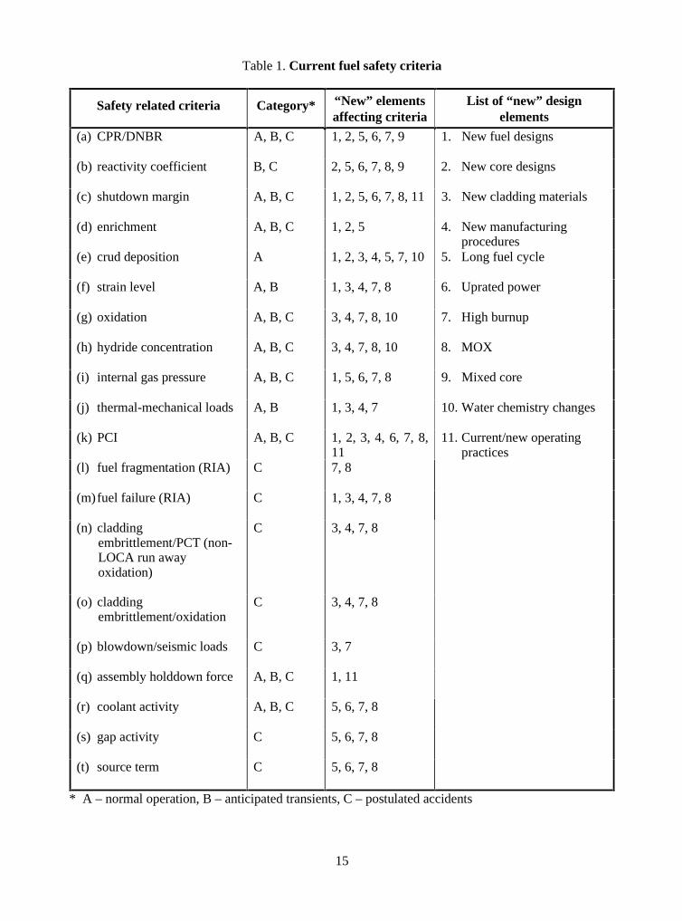
Fuel design should be in concord with the general design criteria [2] that governs the designand operation of nuclear power stations. Thus, existing fuel safety criteria are examined against designelements as applicable to date. Table 1 lists the current fuel safety criteria against those new designelements that may affect them; a list of all new elements considered is provided in this table, whilesome principal elements are highlighted below.
Generally high fuel burnup is of great interest to nuclear operators due to their need forreducing fuel cycle cost, nowadays enhanced by the introduction of electric power deregulation. Thus,high burnup capability is very much in the centre of new design elements, and has triggered activitiesworld-wide. This issue has already been introduced above, and will be addressed for the assessment ofthe individual safety criteria below; in addition, section 5.1 of this report will summarise the highburnup issue separately.
In order to reach high burnup with higher linear heat ratings, the cladding materials forLWR fuel rods used over the last 30 years [based on Zry-2 for BWRs and Zry-4 for PWRs] haveundergone major changes during the last 10-15 years. To reduce the corrosion rate and hydrogenuptake in the metal, the concentration of Sn was reduced (low Sn alloys such as the SIEMENS ELScladding) and Nb containing alloys (e.g. Zirlo of Westinghouse). Apart from the full cladding tubes,several inner and outer liner concepts have been introduced to cope with various performanceproblems (e.g. BWR inner liner for PCI resistance, PWR outer liners for corrosion reduction at highpower).
To achieve high discharge exposures and gain thermal margins, more advanced fuel designswere introduced. The fuel pin geometry changed from coarse pins with large fuel cladding diametersto slimmer pins with smaller fuel and cladding diameters thus reducing the heat flux per claddingsurface area. In the PWR case the number of fuel rods per element was increased from14x14/15x15/16x16 to 16x16/17x17/18x18 pins. The BWR fuel pin number was increased within thesame trend from an 8x8 to a 9x9 or even 10X10 geometry. In parallel to these changes the claddingwall thickness was also reduced and lies today in the range of 0.6 to 0.75 mm which may include aninner liner (barrier) of about 70 µm.
MOX fuel rods differ from UO2 fuel rods only by the fuel pellet material; UO2 is replaced byPuO2-UO2 mixed oxide in which the PuO2 content can vary from 2 to 10 wt% according to the rodposition within the fuel assembly and the design criteria. For the case where MOX fuel has been used,the geometry, the dimensions, and the cladding material are identical for UO2 and MOX rods. In most
14
countries the Pu comes from recycling of “burned” fuel; in addition there is the possibility of burningweapons-grade Pu in commercial reactors in both the USA and Russia. The introduction of new,advanced and/or MOX fuel leads to a mixed core situation, i.e. fuel assemblies of different designsjointly reside in a core. This issue will be addressed separately.
With the severe thermal duty that occurs with some of the current fuel managementstrategies, and in order to reduce radiation levels in plant components, strategies with modified waterchemistry with e.g. higher Lithium concentration, resulting in higher pH values, or with the injectionof Zn or Fe into the primary coolant for reducing dose rates or increased corrosion protection, havebeen introduced in the last years. This chemistry, for example, has proven to be adequate to controlcrud deposition. Notwithstanding that, as the plants in transition to longer operating cycles requireextra loading of soluble boron at beginning-of-life, to maintain the pH at the required level (around7.2) with this boron concentration the fuel has to be operated with high lithium concentration (above2.2 ppm) during sometime, which could increase the corrosion rate.
Hydrogen may be added to the coolant to decrease the amount of oxygen present, which isformed by radiolysis, which consequently decreases the zircaloy oxidation rate. If the hydrogenconcentration is increased too much, cladding hydriding and subsequent embrittlement could beincreased. In some cases hydrogen is added to reduce the recirculation piping radiation dose rates;noble metals may be injected simultaneously, to limit the amount of added hydrogen.
2.3 Task Force approach to assessing the potential effects of new elements
Numerous criteria related to fuel damage are used in safety analyses: these criteria maydiffer from country to country. Some are used to minimise cladding degradation during normaloperation. Some are used to maintain cladding integrity during anticipated transients, thus avoidingfission product release. Some are used to limit fuel damage and ensure core coolability during design-basis accidents, and some are used to limit the public risk from low probability severe accidents.
It can be difficult to categorise these criteria according to event type. For example, limits aresometimes placed on cladding oxidation during normal operation to ensure good operationalperformance, while in other instances such oxidation limits may be linked to cladding mechanicalstrength for LOCA performance.
In Table 1 fuel-related criteria are therefore listed without attempting to categorise themaccording to event type or risk significance. We will leave the matter of relative importance of thesecriteria to the regulatory agencies and others who utilise this information. For each of the criteria inTable 1, we present a brief description of the criterion as it is used in several applications along withthe rationale for having such a criterion.
New “elements,” such as different cladding materials, higher burnup, and the use of MOXfuels, can affect fuel-related margins and, in some cases, the criteria themselves. In the followingparagraphs, some of the more important effects are mentioned in order to indicate whether the criterianeed to be re-evaluated. The following discussion may not cover all possible effects, but should besufficient to identify those criteria that need to be addressed.
15
Table 1. Current fuel safety criteria
Safety related criteria Category* “New” elementsaffecting criteria
List of “new” designelements
(a) CPR/DNBR A, B, C 1, 2, 5, 6, 7, 9 1. New fuel designs
(b) reactivity coefficient B, C 2, 5, 6, 7, 8, 9 2. New core designs
(c) shutdown margin A, B, C 1, 2, 5, 6, 7, 8, 11 3. New cladding materials
(d) enrichment A, B, C 1, 2, 5 4. New manufacturingprocedures
(e) crud deposition A 1, 2, 3, 4, 5, 7, 10 5. Long fuel cycle
(f) strain level A, B 1, 3, 4, 7, 8 6. Uprated power
(g) oxidation A, B, C 3, 4, 7, 8, 10 7. High burnup
(h) hydride concentration A, B, C 3, 4, 7, 8, 10 8. MOX
(i) internal gas pressure A, B, C 1, 5, 6, 7, 8 9. Mixed core
(j) thermal-mechanical loads A, B 1, 3, 4, 7 10. Water chemistry changes
(k) PCI A, B, C 1, 2, 3, 4, 6, 7, 8,11
11. Current/new operatingpractices
(l) fuel fragmentation (RIA) C 7, 8
(m)fuel failure (RIA) C 1, 3, 4, 7, 8
(n) claddingembrittlement/PCT (non-LOCA run awayoxidation)
C 3, 4, 7, 8
(o) claddingembrittlement/oxidation
C 3, 4, 7, 8
(p) blowdown/seismic loads C 3, 7
(q) assembly holddown force A, B, C 1, 11
(r) coolant activity A, B, C 5, 6, 7, 8
(s) gap activity C 5, 6, 7, 8
(t) source term C 5, 6, 7, 8
* A – normal operation, B – anticipated transients, C – postulated accidents

17
3. REVIEW OF SAFETY CRITERIA
In this Chapter, the possible implications from new design elements on all currentlyapproved fuel safety criteria are discussed. An assessment of the need for re-evaluation will be givenalong with each individual criterion. Throughout this review, the basis for the safety criteria isassumed to be unchanged from the original basis [2].
Research is being conducted by various organisations around the world on the effects of newdesign elements such as different cladding materials, higher burnup, and the use of fissile plutonium inMOX fuels. The TFSSC has made an effort, through its members and through its contacts with theindustry, to identify such research related to the individual fuel safety criteria and the need, if any, foradditional efforts in this area.
3.1 CPR/DNBR
The most widely used safety criteria for cladding integrity are related to critical heat flux.These are the critical-power ratio (CPR) for BWRs and a departure-from-nucleate-boiling ratio(DNBR) for PWRs. In a PWR the critical heat flux occurs when the bubble density from nucleateboiling in the boundary layer of the hot rod is so great that adjacent bubbles coalesce and form avapour film across the surface of the rod. Heat transfer across the film is relatively poor such that, ifthe heat flux is further increased (or the coolant flow is reduced), the cladding temperature would riserapidly and substantially. Cladding melting or rapid oxidation could then take place and result infailure of the cladding. Similarly, in a BWR the critical heat flux at the onset of transition boiling mustnot be exceeded.
CPR and DNBR limits ensure that only a very small amount of fuel cladding (0.1% of allfuel rods, in most countries: in Germany, DNB shall not occur for the highest rated rods) isstatistically (95/95 level) expected to fail during anticipated operational occurrences (AOO), andindicate when fuel failure occurs during postulated accidents so that off-site doses can be estimated.To also maintain adequate fuel performance margin during normal steady-state operation, an adder isusually applied to the safety limit CPR/DNB, which corresponds to the heat flux increase during theworst AOO; this constitutes the operating limit that is continuously verified during plant operation.
The CPR/DNBR safety limit is derived from a statistical analysis, in which the fuel assemblyspecific heat flux characteristics are accounted for with a specific core loading. Historically genericbounding assumptions were made on the core loading (using a so-called “reference core”); in this way,the safety limit depends only on the fuel assembly characteristics and is not re-evaluated unless thefuel type changes. In view of advanced fuel and core designs, mixed core situations and to reduceunnecessary conservatism, the safety limit is nowadays often re-evaluated based on the cycle specificcore loading and thus becomes a cycle specific limit. This way, all necessary details of the actual fueland core design are accounted for.
The statistical method to establish the safety limit is usually based on a Monte Carlotechnique, that calculates the critical heat flux for each assembly in the core, at multiple exposure
18
points during the cycle, while introducing random variations in the input variables (manufacturingdata, plant measured data, critical heat flux correlation) based on their known uncertainties; also themodel uncertainties are treated statistically.
The critical heat flux correlation links the critical heat flux and the operational parameters;this correlation is a mathematical fit to data from full-scale tests (Note: PWR tests typically employ asmaller rod array) that the fuel supplier performs for every assembly design specifically. Thus, thecritical heat flux correlation is fuel assembly type specific. The correlation parameters includepressure, flow, subcooling, power peaking within the assembly and axial power shape; tests areperformed while varying each of these parameters separately. To reduce the amount of (timeconsuming and costly) testing, hydraulic (subchannel) models such as VIPRE or COBRA are utilisedto form a “response function” to variations in certain variables; after sufficient validation of thesemodels against test data, further tests may then be reduced. The same critical heat flux correlation isused for core monitoring, to derive critical heat flux for the actual operating point (heat balance etc.).
As a consequence, CPR/DNBR safety limits may be considered to properly reflect themodern fuel and core designs; it is one of the few areas where statistical methods are appliedconsistently, with a rigorous uncertainty treatment. Fuel suppliers have developed critical heat fluxcorrelations (e.g. W-3, GEXL) that are successfully applied world-wide; to date, no fuel has failed dueto inadequacies in establishing these safety limits.1 Although it appears that there is no need to changeeither the safety criteria or the methods to establish them, some testing seems to be needed. Thisincludes full scale testing to establish the proper thermal-hydraulic modelling of new assemblydesigns. Also, statistical methods are to follow method improvements such as the detailed pin powercalculation capability of modern 3-dimensional steady-state methods.
In addition, a concern that is related to high burnup ought to be addressed. Fuel rod heattransfer characteristics are likely to be affected by heavy oxide coatings (which sometimes exhibitspallation) that may appear on cladding at high burnup, or by heavy crud layers. CPR and DNBRcorrelations are, in general, developed from data on unoxidized, or lightly oxidised, fresh claddingtubes and may not be accurate for high-burnup cladding. Material and fabrication variations may makesmall changes in heat transfer characteristics, but the effect of oxidation on surface conditions could bean important effect.
3.2 Reactivity coefficient
The concept of reactivity coefficients has been introduced in order to simplify the analyticaltreatment, e.g. quantifying the feedback reactivities in the point kinetic equation and increase in theunderstanding of reactivity changes due to various physical parameters. Reactivity coefficients arethus an analytical matter; in terms of LWR safety criteria, there is a general requirement that the totalof all reactivity coefficients be negative when the reactor is critical, for providing negative reactivityfeedback (or that the effects of any positive reactivity coefficient be inconsequential).
1. The 1988 dry-out fuel failures in Oskarshamn 2 (Sweden) were caused by excessive channel bow and
incorrect core monitoring model input data. A total of 4 rods operated around 20-30% in excess of the safetylimit CPR for several months prior to failure.
19
The reactivity coefficients depend on the following four reactor core state variables whichare to some extent independent of each other:
• fuel temperature Tf
• moderator (coolant) temperature Tm
• steam volume (void) fraction in the coolant (µ)
• system pressure Ps
The fuel temperature or Doppler coefficient dρ/dTf , where ρ is reactivity, respondspromptly to the enthalpy deposited in the fuel, whereas the other coefficients are delayed. The fueltime constant, which depends mainly on the fuel specific heat, conductivity and diameter, affects thetime delay of changes in moderator temperature and void fraction. The fuel temperature coefficienttherefore depends on the fuel burnup. The higher the burnup the harder the spectrum, so in general thechange of the fuel temperature coefficient with burnup is small in light water reactors.
The strong negative void coefficient in BWRs gives these reactors inherent stabilisingcharacteristics without operator intervention. In modern fuel designs water is added in the central partof the bundle by special water channels of various geometries inside the fuel assembly, which is notheated up as much as the coolant water in the rest of the assembly and has a much lower void fractionthus producing a less negative void coefficient.
In PWR under normal operating sequences there is no void in the core. However, in the caseof abnormal events like loss of primary coolant or loss of pressure the coolant may start to boil andvoid appears and reduces the neutron absorption in boron which results in a positive contribution tothe void coefficient. At operating temperature when the boron concentration is low, this effect will besmall and the void coefficient remains negative. At low temperature when the boron concentration ishigh, the effect is large and the void coefficient may turn positive.
An increase of the moderator/coolant temperature Tm causes mainly two effects:
• the density of the water decreases and the effect is similar to that of void increase;
• the thermal neutron spectrum becomes harder and so the effective neutron cross-sections change.
In a PWR with a strongly borated coolant dρ/dTm is negative at normal operating conditionsbut is slightly positive at lower temperatures. Due to the higher fuel burnup, the moderatortemperature coefficient is becoming also more negative at the end of the cycle. This has some impacton cooling down accidents such as the steam line break accident because more positive reactivity isintroduced from the cooling and the reactor returns to a higher power level than before.
The system pressure in a BWR is related to the saturation temperature of the moderator.Depressurization of the system will cause flashing, i.e. production of steam bubbles in the water. Suchan event introduces a negative reactivity change in a BWR and does not lead to any safety problem asfar as reactivity is concerned.
The effect of a positive pressure pulse is only of interest in a BWR, where significantvoiding exist. A sudden increase of the system pressure, e.g. caused by a turbine trip, will result in apartial void collapse leading to a positive reactivity change.
20
High fuel burnup usually implies the loading of more reactive fresh fuel bundles. Thisadditional reactivity is compensated by fuel (addition of burnable poison) and core design, keeping inmind that the basic safety criterion (negative total reactivity coefficient) must be fulfilled.
In summary, although the reactivity coefficients may be affected, the effects of new designelements are not considered to affect the corresponding safety criteria themselves.
3.3 Shutdown margin
Attaining reactor subcriticality must be assured either by sufficient reactivity worth ofcontrol rods and/or sufficient boron concentration in the primary coolant.
For control rods, this subcriticality requirement becomes the so-called Shutdown Margin(SDM). SDM is defined as the margin to criticality (keff = 1) in the situation with all control rodsinserted (ARI) and the strongest control rod withdrawn. The SDM should be sufficient for achievinghot zero power; for the BWR, SDM is analysed at cold zero power with a Xenon-free core, forconservatism. The TechSpec limit for SDM, usually of the order 0.3-0.5% ∆K/K, is mostly establishedfrom the assumed envelope of uncertainties in the determination of keff and the control rodmanufacturing tolerances. This limit is usually verified at least during (reload) cycle start-up; designlimits for SDM are usually 1% ∆K/K or higher, to protect against unforeseen systematic biases in theprediction of the keff value.
For the PWR, an increase of boron concentration is required to achieve cold shutdown; thisis provided by the available boron/volume control systems. Generally, for PWR and BWR, the boronSDM is the margin to criticality (keff =1) for the situation in which the emergency boron injectionsystem is activated. The (high) boron concentration should be sufficient to assure that the reactorachieves shutdown without control rod movement; for conservatism, no credit is taken for Xenonpresent in the core. Emergency boron SDM limits are established similar to the above control rodSDM limits, i.e. based on calculational and system uncertainties. Values for the emergency boronSDM range from 1 to 4% ∆K/K, depending on whether the analysis is performed using generic and/orcold reactor conditions or more realistically reflects specific plants/cycles. Normally, the emergencyboron SDM is not explicitly included in plant TechSpecs, but are rather verified analytically as part ofthe safety analysis and reload licensing process.
Highly optimised core designs have often shown a decrease in margin to the SDM criteria(usage of higher enrichment levels, often in conjunction with more burnable poison). However,modern fuel designs are also optimised to improve the SDM performance, and may counteract theseeffects. These fuel and core design strategies are provoked or enhanced by operating strategies to savefuel cycle cost, which includes high fuel discharge exposures, long fuel cycles and/or thermal poweruprates.
In the case of MOX fuel, smaller control rod and boron worths have also reduced the SDMperformance.
These reduced margins have, in some cases, induced plant changes such as:
• use of new control rods with higher worth (more/different absorbing material);
• higher number of installed control rods (if plant design permits);
21
• increase of boron system capacity (if possible);
• use of enriched boron
in order to compensate for the lost margin. Ultimately, fuel and core must be designed such that safetycriteria are met; these criteria have not been challenged so far.
It is judged that the existing SDM criteria themselves are unaffected by the new designelements. However, if realistic or best-estimate modelling is used to establish or analyse these criteria,such models should be well verified; in particular, the associated modelling uncertainty should bequantified in order to assess the margin to safety. For the assessment of modelling adequacy andnecessary verification, see Chapter 4.
3.4 Enrichment
Enrichment limits around 5 wt% 235U are used in connection with criticality considerationsfor fabrication, handling, and transportation. For some high-burnup applications, higher enrichmentsmay be needed. To date, the validation of criticality safety codes and associated cross section librariesfor LWR fuel has focused on enrichments less than 5%. Neither benchmarks of code performance northe bases for extrapolating code performance in the enrichment range of 5-10% have been wellestablished. Moving into this range will require care because the physics of criticality begins to changeas enrichments reach 6% and beyond, where single moderated assemblies can go critical and criticalityof weakly moderated or unmoderated systems becomes possible. Enrichments above 5% will requireredesign of some fuel fabrication and handling equipment and fuel transportation packages. Thepossibility of recriticality during accidents, in particular in severe accident core melt sequences shouldalso be addressed as this could alter the progression of such accidents.
3.5 Crud deposition
Crud deposition on the fuel is usually taken into account for fuel design purposes. Theamount of crud deposited, sometimes as a function of burnup but at least at the end of the fuel lifetime,is a conservatively assumed value which is verified against data from measurements (e.g. crudscrape).Various crud levels are being used by vendors, according to the design models and/or the fuel designsthemselves. Firm (safety) limits on crud deposition are not defined, although the amount of cruddeposited and its composition can be significant to the corrosion performance of the cladding(example: Crud Induced Localised Corrosion, CILC).
New design elements, such as cladding materials and their manufacturing processes, maywell influence the build-up of crud and thereby the corrosion performance of the fuel clad. The crudcomposition could affect the corrosion locally, either by acting as a thermal insulator or by chemicallyfavouring the corrosion process. Also the water chemistry characteristics influence the type andcharacter of the crud build-up: as an example, the ratio of 2-valence to 3-valence components in thereactor water (e.g. Zn/Ni or Fe, respectively) could determine the type of crud (spinel vs. hematite),thus influencing the corrosion rate. Experience has shown that the most important factor to considerwhen implementing the chemistry strategies is to address the correlation between crud deposition andcorrosion kinetics at the same time, because some practices that can be good for one aspect may go inthe opposite direction for the other. New fuel and core designs, high burnup and long fuel cycles areissues that could influence crud build-up through associated changes in cladding materials, surfacearea and power history. No specific limits are directly imposed regarding maximum acceptable crudlevels, but its influence has to be considered both on the thermal models as well as on the corrosionkinetics models.
22
Criteria on crud deposition are considered “derived” criteria, and only indirectly safetyrelated. No firm limits are likely to be needed here as criteria relative to the limiting phenomena(oxidation, hydriding, PCI) are already in place.2
There is a concern with large crud depositions in PWRs leading to boron pick-up, therebycausing distortion of the core axial power profile and reduced SDM: this issue is discussed in section5.6 of this report.
Finally, it must be noted that the industry is undertaking efforts to improve the knowledge ofpossible effects of water chemistry, based on accumulated experience and research work, and toincorporate this improved knowledge in a number of reactor water operating guidelines [3].
3.6 Strain level
Generally conservative design limits are taken for stress (e.g. around 1% yield or tensilestrength at operating temperature) or strain (e.g. 1% max. circumferential elastic and plastic strain, andmax. 2.5% permanent axial and tangential strain – caused by fuel swelling – at end of fuel life.) Themargins from these limits to actual failure stresses and strains are defined from the fuel vendor’sdatabase for a particular fuel, cladding, and burnup range.
These limits, together with others such as PCMI (section 3.9) and fuel rod internal pressure(section 3.8), are used to define the fuel specific thermal-mechanical limit; this limit is expressed as aburnup dependent linear heat rate curve (in W/cm). The curve conservatively bounds all thermal-mechanical phenomena; it is set to cover for transient thermal/mechanical overpower, which rangesfrom about 10 to 50%. For a further discussion of the thermal-mechanical limit, see section 3.9.
Stress and strain analyses are performed by the fuel vendor, with models that are constantlybeing benchmarked against available experimental test data. Benchmarking can also be obtained fromsophisticated fuel performance codes (e.g. the COMETHE or the ENIGMA code.) The use of suchcodes allows the expected fuel duty to be modelled and therefore there is no particular probleminvestigating the effects of new core designs or unusual operating practices.
Because these mechanical properties depend on material composition, fabrication, fluence,and hydrogen content, they will clearly be affected by new design elements, in particular by highburnup. Hence, continuous verification [4] of fuel design models is essential to ensure that the properbasis for design and operation exists.
3.7 Oxidation and hydriding
Oxidation and hydriding are directly related to fuel performance for normal operation,transients and accidents. Oxidation degrades material properties, most importantly the claddingthermal conductivity (with a consequential increase in the stored energy of the fuel), whereashydriding leads to embrittlement; these phenomena are increasingly important at higher exposures, asthe dependence on burnup is not linear. For these reasons, Zircaloy cladding materials have been
2. Unexpected large amounts of crud have recently been observed at the River Bend NPP (USA) associated
with a number of fuel failures. The root cause appears to be thermally-induced accelerated corrosion, due toelevated iron and copper deposits associated with a chemistry excursion early in the operating cycle.
23
highly optimised during the past 10-20 years. For BWRs, the optimisation was directed mainlytowards reducing nodular corrosion, due to the CILC related fuel failures which occurred during the70s and early 80s; a too high degree of optimisation (with very small sized secondary phase particles)may however adversely affect uniform corrosion, which makes the choice of materials andmanufacturing processes a complicated balance act. In recent years, other materials have beendeveloped for PWRs in addition to the standard Zircaloy 4 (e.g. Zr-Nb alloys).
Uniform corrosion rates differ between PWRs and BWRs. With the much lower operatingcoolant temperature and the more corrosion resistant Zry-2 as basic cladding material, uniformcorrosion is much less critical for BWRs; in contrast, PWRs are less susceptible to nodular or localphenomena (e.g. CILC, enhanced shadow corrosion) due to much less oppressive heat transfer andflow conditions.
For design purposes, oxide thickness and hydride concentration limits are normally assumedat end of fuel life. Values are usually in the range of 100 micron and 500-600 ppm, respectively; thesevalues are taken from “experience”, and represent upper bounds on data measured from fuel exposedin commercial reactors. The 100 micron oxide thickness also represents the level at which there is asteep increase in the likelihood of oxide spalling, which will unfavourably influence hydriding growthand hence further oxidation.
In several countries the design limit of a average cladding oxide thickness at end of fuel lifeof 100 micron, and of average hydride concentration of 500-600 ppm, have effectively becomelicensed/approved safety criteria via the approval of fuel vendor design methodologies.3 Also criterialimiting the number of cladding defects due to oxidation are found in some cases. In other countries noexplicit limits are defined; in all cases, however, oxidation and hydriding are considered whenanalysing cladding properties for performing stress and strain related design evaluations.
An oxidation effect which has not been much considered in the past and which could beimportant is fuel bonding induced internal oxidation of the cladding. At increasing burnup the pellet-cladding gap in the fuel rods tends to close due to swelling and cladding creep-down and a bondinglayer is formed between the pellet and the cladding. This bonding can have a deteriorating effect onfuel rod behaviour under irradiation. It prevents the axial transport of fission gases in a fuel rod andinduces a severe pellet cladding mechanical interaction. Due to bonding internal oxidation of the fuelcladding is becoming increasingly important as a function of fuel burnup. At high fuel burnup thebonding effect is important; full bonding occurs at fuel burnup of about 50 MWd/kg. Bonding causesdiffusion of fission products such as I, Cs and Cd into the cladding. These effects cause internaloxidation and embrittlement of the fuel cladding and should be considered when assessing the effectsof oxidation.
In some countries, there are no formal criteria related to oxide thickness and hydrideconcentration. This was considered justified by the fact that oxide thickness and hydride concentrationare not directly responsible for fuel failure. However, oxide and hydride influence stress and strainperformance, and ultimately the fracture toughness, of the cladding material. There is an obviousdirect influence on the initial condition of the fuel rod assumed in the transient and accident analyses,as well as on the level of safety relevant parameters such as fuel temperature and internal pressure.Therefore, consideration should still be given to impose limits on oxide thickness and hydrideconcentration.
3. Unfortunately the interpretation of these criteria is not unambiguous, because the clad region over which the
average is taken is often ill defined.
24
Additional issues, such as the oxide cladding spalling and very high local concentration ofhydrides in the cladding wall, are not covered by the present limitations. Also, from a LOCAperformance point of view, a high hydrogen content (2000 ppm and above) may lead to severe quenchresistance degradation (reference the French HYDRAZIR test data.)
Extensive research, including tests on corrosion rates, and fuel inspection programmes incommercial NPP has led to a basis for burnups up to about 50 MWd/kg; also at even higher burnupssome amount of data is available. Cladding containing new zirconium alloys and multi-layer type fuelcladdings have been developed in recent years, and tested out under irradiation in commercial NPPs(lead test assemblies or rods, some of these programmes with subsequent destructive testing). Suchtests will produce data to cover normal core operation, and will have to be pursued to extend fuelburnup substantially beyond the 50 MWd/kg level. In addition, tests to cover transient and accidentfuel performance will have to be made.
In summary, as corrosion of Zircaloy is probably one of the leading parameters that limit thelifetime of nuclear fuel, there is a rationale for reviewing the adequacy of the current applicable limitson maximum local oxidation and hydriding levels in the cladding, especially in view of theperformance of highly burnt fuel.
3.8 Internal gas pressure
Fission gas release and resulting fuel rod internal pressure is an important aspect of fuelbehaviour. Traditionally it has been a limiting factor in setting the thermal-mechanical limit (see alsosection 3.9.) The fission gas release is dependent on:
• the fuel microstructure and chemistry;
• its development with time; and
• the fuel temperature, which is strongly influenced by the power rating and the burnup.
At high burnup (higher than 40-50 MWd/kg) fission gas release tends to increase rapidly.Also available experiments involving fission gas release under transient conditions, indicate very highfission gas releases in the high burnup region of the fuel; furthermore, fission gas release is stronglyinfluenced by the formation of the peripheral fuel rim at high burnup which is especially important fortransient/accident conditions. These phenomena are not yet well understood, nor can existinganalytical tools predict them satisfactorily.
Increases in fission gas release can lead to high fuel rod internal pressures and could alsolead to a deterioration of the thermal conductivity of the gas in the plenum and, more importantly, ofthe heat transfer between the pellets and the cladding due to the resulting gap size modification. Thefission gas Xe and Kr decrease the thermal conductivity of the helium gas in the gap, which increasesthe fuel temperature; when the gap is closed, this effect becomes less significant. This induces afeedback mechanism since an increased fuel temperature enhances the fission gas release. Due to theabove mentioned thermal feedback mechanism, the fission gas release in various rods can be highlyirregular. The high internal rod pressures can have an important effect on fuel cladding behaviour(ballooning, burst, etc.) under transients and postulated accidents. For example, during a LOCA, thepressure differential across the cladding wall may be inverted within seconds due to early completesystem pressure drop.
Two alternative criteria for acceptable internal gas pressure are currently used in variouscountries by their regulatory authorities. In the first option the rod internal pressure is held below the
25
nominal pressure in the reactor coolant system (RCS) during normal operation in order to preventoutward creep of the cladding. In the other option the rod internal pressure may exceed the RCSpressure, but is limited so that the instantaneous cladding creep-out rate due to an internal rod pressuregreater than the reactor coolant system pressure is not expected to exceed the instantaneous fuelswelling rate, i.e. the fuel to cladding gap does not open (this is the so-called “no lift-off” criterion.) Athigh fuel burnup this could, in transient and accident conditions, lead to a very high internal pressureof the fuel rod with subsequent high stored energy, cladding ballooning and bursting, which couldchallenge core coolability, and thus the level/limits resulting from this safety criterion.
These criteria themselves should not be affected by new design elements, although methodsto demonstrate compliance will be affected.
Furthermore, MOX fuel has been found to produce a higher fission gas release as comparedto UO2 fuel. An acceleration of fission gas release with exposure is observed, also because of thehigher linear heat generation rate in MOX due to the higher reactivity level. More than the criteriathemselves, the issue here is to demonstrate the compliance with the criteria. The development of rodinternal pressure as function of burnup on MOX fuel needs to be well characterised, also inconsideration of the production method and plutonium content in the MOX fuel. The consequence ofrod internal pressure build up must also be carefully studied. One such study, a lift-off test series (IFA610) with UO2 and MOX fuel rods of 50-60 MWd/kg is currently being performed at the Haldenresearch reactor. For the UO2 rod, lift-off occurred at an overpressure of around 130 bar; first resultsfor the MOX fuel rod indicate an even higher lift-off pressure. On the basis of the Halden findings arefined “no lift-off” criterion has been proposed by some vendors, considering outward creeprate/strain and tensile stress due to overpressure.
For a discussion on possible effects of new design elements on the thermal-mechanical(LHGR) limit, see section 3.9.
3.9 Thermal mechanical loads (PCMI)
Pellet-to-cladding mechanical interaction (PCMI) refers to the stress on the cladding from anexpanding pellet, especially during a transient. Pellet expansion results mainly from thermalexpansion, and if the stress is large enough it can result in cladding failure. PCMI differs from therelated PCI phenomenon (see section 3.10) inasmuch as the latter refers to power ramps where thestress is held for a long period of time and corrosion is necessary for cracking to take place.
The avoidance of mechanical fracture of the clad during transients due to PCMI, which is thebasic safety criterion, is traditionally covered by the limit on uniform cladding (plastic and elastic)strain of 1%, as already described in section 3.6.
A range of power-increasing transients where PCMI may be important are addressed inFSAR and reload licensing safety analyses (e.g. loss of feedwater heating in a BWR and steamlinebreak in a PWR). If the PCMI stress is low enough or if the cladding ductility is high enough, PCMIwill not be the mechanism for cladding failure. In those cases, the cladding temperature would risebecause of the increasing power, and eventually critical heat flux might be exceeded and lead tocladding damage. For the latter transients CPR/DNBR fuel integrity criteria are generally limiting, andthese transients are usually analysed from this perspective (i.e. without looking at PCMI.)
Several things might occur at high burnup that could result in early cladding failure byPCMI. First, the pellet-to-cladding gap closes at higher burnup, eliminating some free expansion of thepellet prior to contact with the cladding. Second, the large accumulation of fission gas on fuel grain
26
boundaries will also expand during a power increase, which would contribute to the cladding strain.Third, cladding ductility is reduced significantly by radiation embrittlement already at intermediateexposure such that a mechanical failure becomes more likely. Fourth, cladding hydriding furtherreduces the ductility at high exposure mainly at lower cladding temperatures. Under thesecircumstances PCMI failures could also occur for those transients that were CPR/DNBR-limitedbefore, and thus the critical heat flux type of analysis would then be inappropriate for safetyevaluation.
Experimental data on PCMI for LWR fuel have been obtained from e.g. the Halden reactorproject and the international R&D programme from Belgonucleaire, covering a range of burnup up to60 MWd/kg; so far, none of these results point towards PCMI effects being prohibitive at high burnup.However, as these experiments usually aimed at investigating other high burnup effects such as fissiongas release and thus PCMI data were obtained “on the side”, it appears warranted to perform moretests focusing on PCMI directly.
In summary, some concerns regarding the effect of high burnup exist which should beaddressed by performing more tests focusing on PCMI directly. Fuel design and performance codesmay be used, provided they are well benchmarked, validated, and verified against experimental data.Also, some more testing of PCMI for benchmarking these codes and verifying their results appears tobe justified.
The thermal-mechanical limit (a burnup dependent curve) is established while includingthe PCMI phenomenon, as well as various other phenomena (fuel rod internal pressure, stress/strain,fatigue, fuel melting, clad corrosion and ballooning) that have been discussed elsewhere in this report.The limit is set to bound all these effects; also, the limit includes the effect of thermal and mechanicaloverpower during normal transients (AOO). Traditionally, this implies that conservatism is assumed toaddress uncertainties in various areas: models and model parameters (e.g. fission gas release),manufacturing tolerances, and fuel /core management (e.g. as power histories during operation.) Thus,an overlay of conservatism exists with the margin to the real (nominal) limit not well quantified.
In modern fuel design methodologies the approach is different, namely – similar to theapproach taken for establishing the CPR/DNBR safety limit – on a statistical basis. The parameters inthe areas mentioned above are treated as distributions, with best-estimate uncertainties, and a MonteCarlo model varies all these parameters for the multiple calculation of important design features (e.g.internal rod pressure). With a known design/safety limit the necessary margin may then be identified.
To adequately cover modern fuel and core designs, the already mentioned best-estimatemethods, along with associated uncertainty analysis, should generally be applied in order to reduceunnecessary conservatism. This implies, however, that such methodologies need to be well validatedand verified; thus, experimental tests are to continue to provide the basis for such verification andvalidation.
The basic safety criterion – the avoidance of mechanical fracture of the clad – is not affectedby new design elements, however the current limit (1% strain) may change.
3.10 Pellet cladding interaction (PCI)
Pellet cladding interaction (PCI) failures are due to stress corrosion cracking in the claddingmaterial, which is associated with local power ramps during reactor startup or maneuvering (e.g. rodadjustments/swaps, load follow.) Both the stress from the power increase and the corrosion level in thecladding are necessary conditions for PCI. A crack, initiated at a microscopic defect in the cladding,
27
propagates until the stress in the remaining load-bearing part of the cladding exceeds the ultimatetensile strength, resulting in failure. Fresh fuel rods do not fail by PCI, neither do fuel rods operated atconstant power.
The PCI phenomenon has been extensively investigated after multiple PCI failures duringthe 70s. To control the PCI phenomenon, operating rules (also called management recommendations,or PCIOMRs) to limit local power increases and “condition” fuel to power ramping wereimplemented. These rules are usually a function of exposure (at higher burnup the fuel is less able towithstand ramping) and differ between various fuel types. To establish and validate these rules,extensive power ramp tests were performed – by basically each fuel vendor – notably in theSTUDSVIK and PETTEN test reactors; thus, the failure threshold of the cladding is known very wellup to 40-50 MWd/kg and for power ramps well beyond normal operation. A certain amount of ramptesting has also been performed at higher burnups (up to 60-70 MWd/kg) later on, e.g. in France.Verification of these rules was performed in various commercial NPPs.
The PCI limits/rules typically contain a maximum ramp rate for power increase (inW/cm/hr), a maximum “single step” power increase (W/cm), and a threshold (in W/cm) above whichsuch power increase limitations apply and a minimum time-period after which the fuel may beconsidered (pre)conditioned to larger power ramps.
During the 80s and 90s, PCI resistant fuel types were developed based on a small layer ofzirconium (“barrier” or “liner”, with or without small additives like Sn or Fe) at the inner part of theclad as a more permanent remedy. Also, the modern fuel assembly designs contain more fuel rods andtherefore have a lower linear heat rating for each rod: this way, the fuel may permanently operatebelow the PCI threshold and thus not be in danger of PCI.
The PCI mechanism is sensitive to the gas composition in the gap. At high burnup (higherthan 40 MWd/kg) fission gas release becomes increasingly important and due to increased releases iniodine, cadmium and cesium the gap gas composition is more aggressive and can enhance PCI inducedfuel cladding failure. Since fission gas release from MOX fuel pellets will differ from that of UO2
pellets, a MOX effect is also expected. Also the mechanical interaction between the fuel pelletcladding (bonding) is becoming an increasingly important phenomenon in the high burnup area. Forthese reasons it is important to continue to perform ramp tests especially in the high burnup region, inorder to establish PCI threshold values properly. This is equally important in view of the introductionof new cladding materials.
During transient conditions PCI fuel failure mechanisms must be taken into account. ThePCI failure mechanism may be significant in transients like the control rod withdrawal error (RWE),and in subcooling (cold water) transients generally. It should however be remembered that suchfailures pertain to previously intact fuel, and that therefore the radiological consequences of suchtransients are normally minor.
By and large, PCI limits (rules) are not licensed; each NPP is designed to cope with a certainnumber of small fuel failures, and TechSpec limits (particularly the 131I concentration level in theprimary coolant) will bound plant operation.
Nevertheless PCI rules do pertain to safe fuel performance, and regulators will maintain thatfor non-PCI-resistant fuel these limits be adequate and that NPPs obey these rules for core operation.The PCI limits should be kept updated, to be in concord with the respective fuel and core designenvisaged; this is primarily done by performing ramp tests.
28
At present there is a good basis for PCI limits up to about 50 MWd/kg burnup. Acontinuation of ramp testing is recommended, to improve the basis at the higher burnups and asappropriate to the fuel design adopted. At the same time, fuel performance models should be furtherdeveloped and benchmarked against these ramp tests; finally, with sufficient modelling, the amount oftesting could be reduced.
3.11 Fuel fragmentation (RIA)
To avoid the loss of coolable geometry and the generation of coolant pressure pulses, peakfuel enthalpy criteria are used as limits for reactivity-initiated accidents (RIA). To date, an enthalpyvalue of 280 cal/g has been used in the USA and other countries based on data from early RIAfragmentation measurements prior to 1974 (e.g. SPERT and TREAT tests in the USA); this valuecorresponds to the melting of UO2 which causes fragmentation of the cladding and expulsion of fuelparticles. The expulsion of molten fuel also led to energetic fuel-coolant interactions that generatedpressure pulses. Later refinements in the measurements and in the definition of the fragmentationenthalpy value [5], as well as later FRAP-T calculations and PBF-RIA tests led to reductions of the280 cal/g limit. Accordingly, various regulatory authorities use a lower value for the enthalpy limit.
The original SPERT and TREAT data indicated that the 280 cal/g total energy depositionwas conservative to ensure minimal core damage and to maintain core coolability. Some of those testsalso indicated that a fuel rod subject to a radial average peak fuel enthalpy of 280 cal/g will beseverely damaged, loose its original geometry and impair post-accident cooling; on this basis a revisedcriterion of 230 cal/g was recommended [5].
At the same time, the question whether this limit should be identical for unirradiated andirradiated fuel was brought up (ref. results from the PBF-RIA 1-1 test). Similarly an internationalindustry working party, led by EPRI, suggested a value of around 240 cal/g for fresh and low burnupfuel.
Recent experiments in the French CABRI test reactor and the Japanese NSRR test reactorusing high burnup fuel samples have resulted [5] in fuel particle dispersal for deposited energies wellbelow 200 cal/g. It is clear that, for high burnup fuel, a mechanism other than fuel melting isproducing particle dispersal at low deposited energies. This new mechanism may possibly be relatedto the large accumulation of fission gas bubbles on grain boundaries of the fuel and the rapidexpansion of that gas during the power pulses, with special emphasis in UO2-RIM and MOX clusters.Entrainment of particles in escaping fission gas may also be involved. Various effects (pulse width,cladding type, coolant type, internal pressure, coolant temperature), some of which are not yet wellunderstood, may play a role: however the burnup effect in UO2 is evident.
Of special interest is the formation of a peripheral zone in the fuel material with highplutonium content and consequently high reactivity, porous structure and high content of fissionproducts, the so-called RIM, that grows as a function of exposure: at about 45 MWd/kg the RIM-zoneis of the order of 200 µm. Fundamental studies are being performed to clarify what role the RIM-zoneplays in transient/accident situations.
Because pellet structure and fission gas release from MOX fuel pellets will differ from thosein UO2 pellets, an additional MOX effect is also apparent [17,18].
To summarize, from a safety point of view, it is considered that the analytical verification ofmeeting the limit in the range of around 230-280 cal/g may well be sufficient to ensure a coolablegeometry for fresh and very low burnup fuel. For the assessment of this limit at high burnups there is a
29
need for further understanding of the fragmentation process and the effects of high burnup (inparticular the effect of the RIM-zone and the MOX clusters) thereon. Verification against morerealistic RIA experiments (planned with the CABRI – water loop) is therefore desired. This improvedunderstanding should also contribute to better modelling with fuel performance codes (see Chapter 4).
3.12 Fuel failure (RIA)
For a RIA, the number of fuel rod failures must be calculated so that the radiological dosesto the public can be estimated. In most countries the current fuel failure limit is based on the definitionper section 4.2 of the US Standard Review Plan [7] as a maximum radially averaged fuel enthalpy of170 cal/g for BWRs and as a DNB criterion for PWRs. Based on some of the RIA experiments atCABRI and NSRR during the 1990s, with fuel rods at a burnup of approx. 50 MWd/kg or higher, anassessment of the adequacy of this limit appeared desirable. In this respect, various limit values asfunction of burnup have been proposed based either on direct experimental data renditions or onrelevant parameters, such as cladding oxide thickness.
Results from all RIA tests (SPERT, PBF, CABRI, NSRR) with Zircaloy-clad fuel aboveabout 5 MWd/kg show failures from a pellet-cladding mechanical interaction (PCMI) rather than high-temperature failures related to critical heat flux [8]. It is believed that the reduction in gap and ductilitydue to radiation creep and embrittlement/hydrogen absorption is responsible for the change in claddingfailure mechanism for irradiated fuel (in the case of UO2-RIM or MOX clusters, fission gas-inducedfuel swelling is another contributing factor). Thus the effects of burnup appear to alter the failuremechanism and make the critical heat flux criteria inappropriate. Since ductility will also be stronglyaffected by changes in cladding materials (e.g. the use of Nb as an alloying agent), the effects of newcladding materials on RIA fuel failure may also be important. For example, IGR tests with Zr-1%Nb-clad VVER fuel show completely ductile behaviour without PCMI failure even at high burnup (thesetests was performed with a pulse width of about 700 ms); BIGR tests show no PCMI failure up to160 cal/g enthalpy at 48 MWd/kg (here the pulse width is 3 ms) [9].
Thus, especially in the higher burnup range where experimental data are lacking, technicallybased safety criteria and verification of the analytical models for fuel performance should be pursued.Here the future experimental CABRI programme, which test facility will be modified to include aPWR water-loop, is likely to provide very valuable results. The importance of the post-DNB conditionhas already been demonstrated in early PBF tests [5] on fresh fuel rods, which resulted in highoxidation and embrittlement during film boiling, and cladding fracture and fuel powdering during rodquenching; therefore, further investigation for high burnup fuel under realistic conditions appearswarranted, and the CABRI water loop could be very useful for such investigation.
Also NSRR and separate effect tests in facilities like PROMETRA, PATRICIA, SILENE(France) and from the ANL – test programme [13] (USA) as well as the JAERI – test programme [17](Japan) should provide worthwhile information.
3.13 Cladding embrittlement/PCT (non-LOCA run away oxidation)
Certain non-LOCA accidents are analysed to estimate radiological doses to the public and todemonstrate that coolability of the core is maintained. For accidents like the PWR locked rotoraccident, DNB is used to indicate cladding failure for dose calculations, and 2 700°F is sometimesused to demonstrate coolability. The 2 700°F limit was taken from early data estimates of the fuelfailure boundary for LOCA conditions (2 700°F and 17% of clad thickness oxidised by metal-waterreaction). This limit was established in the 1969-1971 time period prior to the ECCS hearings in the
30
U.S., which resulted in a lower temperature limit for LOCA analysis (2 200°F or 1 204°C.) Therationale for retaining a higher temperature limit for non-LOCA transients was that those transientswere of brief duration and fuel rods could withstand brief periods of DNB without suffering seriousdamage.
This peak cladding temperature criterion is a measure of the amount of oxidation that cantake place during the transient and the related loss of ductility. Because oxidation and hydrogenabsorption also take place during normal operation, this will cause a further reduction of ductility athigh burnup. Therefore, the peak cladding temperature during the transient may have to be adjusted toaccommodate normal corrosion. Since cladding ductility is also affected by cladding materials (e.g.,the use of Nb as an alloying agent), an effect of cladding materials would also be expected for thiscriterion.
The behaviour of highly burnt fuel under this condition is relatively unknown. The relevanceof the above criterion should therefore be confirmed experimentally.
3.14 Cladding embrittlement/oxidation (LOCA)
For LOCA analysis, it is generally assumed that a certain amount of fuel rods fail and releasefission products, but that emergency core cooling systems (ECCS) operate in such a way that fuel rodfragmentation is avoided, thus preserving a coolable geometry, and moreover provide long term corecooling. Based on many laboratory quenching and ductility tests with unirradiated zircaloy tubes, itwas found that cladding would not become embrittled enough to fragment if the peak claddingtemperature remained below 2 200°F (1204°C) and the total oxidation did not exceed 17% of thecladding thickness before oxidation. These embrittlement criteria (reference 10CFR50.46) are usedwidely, although in some cases the oxidation limit is placed at 15% (e.g. Japan).
In addition there is a LOCA limit on hydrogen generation, however this is rather forcontainment integrity than against embrittlement (limit is usually 1% related to total possible cladoxidation).
The embrittlement/oxidation criteria were developed in the 60s and early 70s; experimentalverification and validation included tests with zero or low burnup fuel. Nowadays fuel operationexhibits typical oxidation levels of up to 100 microns and hydrogen concentrations up to 500 ppm atthe time of discharge (these levels are usually employed as criteria for fuel mechanical design, whichfrequently become licensed limits, see section 3.7). Hence the 17% criterion is now often interpretedas “total” oxidation level. As the oxidation process at LOCA temperatures differs from that at normaloperating temperatures, this interpretation may be considered as being very conservative; the questionwhether the oxidation during normal operation should be accounted for when comparing against the17% LOCA-limit is unsettled, and will hopefully be resolved from the ongoing French [10] andJapanese [17] as well as the planned ANL [13] experiments. A different criterion, that might be moresuitable especially at high burnup, could also be envisaged.
There is a number of issues and concerns that necessitate additional verification andsubsequent justification or adjustment of the current LOCA limits. Some of these are related to highburnup:
• radiological consequences: extent of rods burst, and fission product release;
• consequences from hydrogen-induced ß-phase stabilising effect on clad strain;
31
• consequences from fine fragmentation of the fuel, filling the space in the ballooned clad(also the timing of slumping of the fuel column into the ballooned area is important, aswell as the consequences of additional decay heat related to cladding temperature andoxidation);
• clad behaviour during quenching and long-term cooling: changes in oxidation rate andclad embrittlement, UO2-RIM or MOX clusters fission gas induced fuel swelling (lossesin mechanical strength may become important if clad wall strength is significantlyweakened during irradiation);
• modelling accuracy, e.g. clad thickness calculation after burst or adequacy of Baker-Justoxidation correlation;
whereas some are of a more generic nature:
• fuel relocation in the ballooned region;
• potential subchannel blockage.
Some of the concerns and issues mentioned above could well be addressed by performingout-of-pile (e.g. hotcell) experiments on ballooning, corrosion and fracturing. A number of researchprogrammes are already ongoing (e.g. in France: TAGCIS, TAGCIR, HYDRAZIR [11], CINOG,EDGAR [11] and in Japan at JAERI [17]) or have been initiated (e.g. in the USA at ANL [12], with avery comprehensive test programme) which include integral as well as separate effect tests.
The USNRC has been examining the 10CFR50.46 Appendix K requirements [13], whichimpose conditions governing LOCA analysis, in recent past. For future verification and review ofLOCA safety criteria, the results from this examination should be taken into account.
On the whole, LOCA safety criteria are still considered adequate for modern fuels to meetthe basic limitations on core coolability and radiological release. It is believed, that the results of theabove tests along with complementary ductility tests for long-term LOCA behaviour, should besufficient for verifying the current safety criteria, especially for the effect of burnup, and to furtherdevelop and validate LOCA modelling.
3.15 Blowdown/seismic loads
During a seismic event the fuel assemblies are subjected to dynamic, structural loads whichcould cause fuel assemblies to sway back and forth, causing impacts with each other and with thevessel wall. Jet forces associated with blowdown from one side of the vessel through a broken pipecould also accelerate the vessel in the lateral direction, resulting in similar impacts between fuelassemblies and vessel wall.
Analyses usually include the consideration of mechanical and hydraulic loads in horizontaland vertical directions; critical crushing loads are used to determine if such impacts cause griddeformation that reduce coolant flow and degrade ECCS performance. Other mechanical propertiesare used to ensure that fuel rods do not fragment, thereby losing coolable geometry, and that guidetubes and channel boxes do not fracture and prevent control rods from being inserted.
32
Most countries follow the safety criteria as per NUREG-0800, SRP 4.2, App. A whichrequire core coolability and control rod insertability to be assured under the combined seismic andLOCA loads. These criteria are often translated into design requirements such as:
• fuel rod fragmentation shall not occur (can be met by verification that fuel rod stressesare within limits per ASME III, App. F);
• control rod insertion shall not be impaired (verify that combined loads do not displacethe fuel assembly from the support piece, that stresses are within the above ref. limitsetc.);
• limit spacer distortion to ensure rod coolability (verify that spacer distortion or failuredo not occur).
Verification is performed analytically. As fuel designs may have different dynamicproperties, this analysis is not only fuel design but also core design dependent; in particular, the mixedcore situation (see also section 5.4) should be addressed explicitly.
Safety criteria in these areas are not directly affected by the new design elements; however,considering the analytical verifications just mentioned, methods used to analyse the seismic/LOCAevent should be well verified and validated.
Also, design requirement changes on allowable structural loads for earthquakes during andafter a LOCA may be needed at high burnup, because the strength and ductility of high-burnupcladding, guide tubes (PWRs), and channel boxes (BWRs) will not be the same as for fresh material.Analyses for fresh fuel usually show ample margins, and the increased strength at high burnup wouldseem to enlarge those margins. But the method of review presumes that the material being analysed isductile, whereas a substantial loss in ductility occurs at high burnup for some materials. Alteredmaterials properties for high-burnup cores and for new core materials may well affect the results ofthis structural analysis; thus, adequate treatment of these properties is needed, which implies thatmaterial properties verification at high burnup is of importance.
3.16 Assembly holddown force
LWR fuel assemblies are equipped with holddown springs in the top piece. They have toprovide sufficient forces to prevent fuel assembly lift-off due to hydraulic loads during normaloperation and anticipated operational occurrences, with the exception of the hot pump overspeedtransient (for the hot pump overspeed transient some lifting is tolerated; the holddown springs shallagain prevent fuel assembly lift-off after the transient has subsided.)
Safety criteria are usually defined following NUREG-0800, SRP 4.2, App. A: vertical lift-offforces must not unseat the lower fuel assembly tieplate from the fuel support structure.
The required holddown force is calculated by:
F HD = F HY + B - W
where
F HD required holddown force
F HY hydraulic force
33
B buoyancy force
W fuel assembly weight.
The hydraulic force on the fuel assembly depends on the coolant flow rate and the fuelassembly pressure loss coefficient. A conservatively high flow rate (mechanical design flow rate) isused for calculating the required holddown force. The uncertainties and tolerances are taken intoaccount differently by the fuel vendors, but in general the following uncertainties and tolerances aretaken into account:
• tolerance of axial spaces between lower and upper reactor core plate;
• tolerance of assembly length;
• tolerance of fuel assembly weight;
• uncertainty of the coolant flow rate;
• uncertainty of pressure loss coefficients;
• uncertainty of holddown spring deflection curve and spring constant;
• uncertainty of guide tube axial growth;
• uncertainty of spring relaxation.
The analytical evaluation of required holddown force is done for cold start-up conditions andhot full power conditions, at BOL and EOL.
The fuel assembly holddown force leads to compressive forces on the guide tubes, whichforces can give high fuel assembly bow due to irradiation induced guide tube creep. Vice versa, highcompressive forces can result from excessive guide tube growth.
Guide tube growth is correlated to the fast neutron fluence and therefore a majorconsideration at high burnup levels, where high corrosion and hydrogen pickup of the guide tubeaccelerate guide tube growth above the fast neutron irradiation induced rate. Corrosion and hydrogenpickup highly depend on the coolant temperature and on the guide tube material and its condition.Thus, to ensure acceptable guide tube corrosion and hydrogen pickup, guide tube design and materialhas to be selected adequately.
In summary, safety criteria are not considered to be affected by new design elements. For theanalytical verification of these criteria, it is important that sufficiently well validated and verifiedmodels are in place; also, material properties need to be available, especially at high burnup, to be ableto choose and analyse materials adequately.
3.17 Coolant activity
In most countries, limits are specified in the plant Technical Specifications on theconcentration of 131I (sometimes also of 137Cs) in the primary coolant; numbers are typically around2x109 Bq/t. This allows the NPPs to operate with a certain (small) number of fuel failures; the plantsystems have been designed to cope with fuel failures of this magnitude. Aside from this TechSpeclimitation, no fuel safety criteria on coolant activity exist.
34
Usually, as soon as larger 131I concentrations are measured that would challenge theTechSpec limit, the plant operational staff prepares for plant shutdown to identify and replace theleaking bundles, so that plant operation within TechSpec limits may be continued.
From large cracks in the fuel rods (direct contact between fuel and coolant) washout of fuelmaterial from the pellet may occur, subsequently leading to a high concentration of Neptunium. Evenafter the leaking fuel has been removed, it may take a long time (several years/cycles) for thisconcentration to decrease as fuel material is plated out throughout the primary system; this implies thatsmall amounts of washout from later fuel failures cannot be observed from the Np-concentration dueto the large background already available. Thus, a pure correlation between actual Np-concentrationand fuel failures does not appear to be possible; nevertheless, most fuel vendors analytically associateNp-concentration with the size and number of fuel leaks from. A future TechSpec limit on the Np-concentration may be needed to avoid operation with large fuel failures with substantial amounts ofwashout.
No change of the above limit(s) is expected in conjunction with new design elements.
3.18 Gap activity
During normal reactor operation, some fission products come out of the UO2 fuel matrix andcollect in the gap between the fuel pellet and the cladding. Fixed values of release to the gap, like up to10% of the rod inventory for noble gases and 1-6% for halogens and alkali metals, are assumed insafety analyses. These gap activities are then assumed to be released from failed fuel rods for thepurpose of off-site dose calculations for postulated accidents. The release fractions assumed are notsafety criteria, but represent conservative numbers used for design purposes.
Volatile fission products are not very soluble in the UO2 matrix, and most of these fissionproducts take up residence in the form of gas bubbles that become attached to grain boundaries. Atvery high burnup the grain size becomes smaller in the RIM zone, and also leads to the formation ofhigh number of micro-sized pores in which the fission gas is supposed to be contained; yet, these poresare not interconnected and do not significantly contribute to the gap inventory since the gap is closed.However, gas bubbles become interlinked along the boundaries in the fuel centre, providing easierpathways for release to the gap. Hence fission product release to the gap is found to increase at highburnup; a similar enhancement compared with UO2 is seen for MOX fuel. These increases in releasemay require the modification of assumptions about gap activity that are used in safety analyses.
3.19 Source term
During and immediately following an accident, the part of the fission products inventory,released into the containment, potentially available for release to the environment is called the sourceterm. Also, in most countries, a severe-accident source term (associated with core melting) is defineddeterministically to estimate radiological releases to the public for beyond design-basis accidents.Source terms are also used in PRAs to estimate plant releases and accident consequences.
Source terms are based on measured releases from irradiated fuel, tested under accidentconditions, in combination with assumptions or analyses of the effects of retention or enhancementduring the course of an accident sequence.
Source terms related to design basis accidents are calculated regularly, in conjunction withsafety analyses for licensing of new fuel designs/core loading strategies, to evaluate radiological
35
consequences. Thus, changes due to new design elements are accounted for, which may lead tochanges in source term levels. However, the assumptions or analytical procedures themselves are notexpected to change.
There are no safety criteria directly associated with source terms. Various assumptions aremade for the analysis of accident scenarios and for retention effects etc.; in part these are rooted in thebasic reactor design philosophy, and can vary significantly between various regulatory frameworks.Although these differences are known, attempts to unite the analytical procedures and assumptionshave not been very successful thus far.
The effect on source terms from new design elements – especially from high fuel burnup – isestimated as follows:
The main effects that could impact source terms as well as core melt progression at highburnup are:
a) a reduction in the amount of unoxidized zirconium in the core;
b) embrittlement of the fuel cladding;
c) an increase in the release of fission gases from fuel pellets during normal operation;
d) fragmentation of fuel pellets; and
e) a shift in the spectrum of fission products produced as plutonium fission becomes moreimportant. Effects (c), (d), and (e) could, in principle, also impact source terms forMOX fuel.
A reduction in the amount of unoxidized zirconium metal in the core could diminish theseverity of core melt and subsequent ex-vessel phenomena by lowering the reaction heat from metaloxidation. However, the amount of preoxidation of the cladding will be less than 15-17% of the wallthickness because of regulatory limits related to LOCA, and is likely to be much lower than that fornewer cladding alloys; therefore, this beneficial effect would be small. Non-molten fuel relocationmay occur due to cladding embrittlement, particularly for scenarios involving delayed reflood ordepressurization, but this is not expected to significantly affect the overall outcome of uninterruptedcore melt accidents. Gap activity comprises only a small part of the source term so that even largechanges in gap activity would not have a big effect on the source term. Fuel fragmentation has beenobserved at high burnup, but it appears that dispersal of fragments occurs by washout or gasentrainment and there may be no means to get that material into the atmosphere as aerosol particles. Incontrast, particulate releases included in the source term are lifted from the core as high temperaturegases that condense as aerosol particles. The source term itself is defined by release fractions andtherefore would not be affected by isotopic shifts. Those shifts would be accounted for in thegeneration analysis (e.g. with an analysis code such as ORIGEN): anyhow changes are expected to besmall, yet experimental programmes are being undertaken to provide an adequate validation basis forthese analysis codes at higher burnups.
Considering the above factors, it is unlikely that high burnup will have a significant effect onsource terms or core melt progression. A similar statement can be made about MOX fuel, particularlyin light of the diminishing difference between MOX fuel and UO2 fuel as burnup increases. It shouldbe noted, though, that this conclusion is based on a limited assessment and might be altered by a morethorough evaluation. Also, the implementation of a revised source term [14] could affect thedependence on new designs and materials.

37
4. ASSESSMENT OF ANALYSIS METHODS
Code development activities are wide spread, and the models and correlations involved inthese codes are numerous in comparison to the fuel safety criteria discussed above. Therefore, theTask Force will not attempt to identify all development programmes and the many models andcorrelations involved. However, it is of interest to assess which models and correlations would beaffected by new design and operational elements. In this section, a general attempt will be made toidentify the weak areas with the use of several examples of ongoing development work.
Analytical methods (computer codes) are extensively used in safety analysis, either as stand-alone codes or in a coupled manner. Thus the methods emphasis in safety analysis is on transients andaccidents; however, steady-state analysis is also needed to establish initial conditions. For example, forLOCA analysis it is very important to have an accurate value for the stored energy of the fuel pellets atthe time the accident is initiated which can be released during the accident: this stored energy comesfrom a steady-state calculation for normal reactor operation. Also, for deeper understanding of RIAfailure mechanismus it is very important to have accurate values for the fission gas content in grainboundaries and porosities at the time of accident initiation, especially for UO2-RIM and MOX clusterswhich may promote fuel swelling and grain separation during the accident; this fission gas content isobtained from a steady-state calculation at normal operating conditions.
Several types of computer codes that are used in safety analysis are sensitive to fuel-relatedparameters. In the previous Chapter, the need for further code development and verification has beenstated on many occasions; new design elements, such as different cladding materials, higher burnup,and the use of MOX fuels, can affect the performance of these codes. In the following paragraphssome of the more important impacts on these codes are mentioned in order to assess if the codes mightneed further verification or even modification. Examples are given rather than systematically coveringall possible models and effects; this should still be sufficient to identify analytical areas that need to beaddressed in more depth.
4.1 Steady-state fuel rod codes
These single-rod codes, like FRAPCON, COMETHE, TRANSURANUS, METEOR andTOUTATIS calculate thermal quantities such as radial temperature profile and fission gas release tothe gap, and mechanical quantities such as creep deformation and irradiation growth. Results are usedfor many purposes like axial clearance between rods and end fittings, internal gas pressure to comparewith system pressure, cladding oxide thickness to compare with established limits or to initiatetransient calculations, stored energy for LOCA analysis and fission gas repartition between grains,grain boundaries and porosities for RIA fuel failure mechanisms studies. These codes consist ofnumerous models and correlations to describe gap conductance, material properties such as thermalconductivity and specific heat, radial power profiles, stress-strain equations, mechanical properties,creep properties, fuel-swelling, fuel-densification, waterside corrosion, and hydrogen absorption.
In recent work in the U.S., the FRAPCON steady-state fuel rod code was modified [15] forburnup up to 65 MWd/kg. Previously the code had been validated up to about 40 MWd/kg. Nine
38
models within the code were found to need modification because burnup effects on the phenomenabeing modelled were large enough to warrant a change. Those models were:
• fission gas release;
• fuel thermal conductivity (including effects of burnable absorber additions);
• fuel swelling;
• fuel pellet cracking and relocation;
• radial power distribution;
• solid-solid contact gap conductance;
• cladding corrosion and hydriding;
• cladding mechanical properties and ductility;
• cladding axial growth.
It is expected that this experience would be typical for other fuel rod codes at high burnup.For different cladding materials, of course the cladding-related models like corrosion, mechanicalproperties, and growth would be affected. Similarly for MOX fuel pellets one would expect changes inradial power distribution, fission gas release and thermal conductivity, and perhaps also in swelling,cracking and relocation (see e.g. the COMETHE model development for high burnup MOX fuel basedon Halden experiments).
4.2 Transient fuel rod codes
These single-rod codes, like FALCON/FREY, FRAPTRAN, and SCANAIR also calculatethermal quantities and mechanical quantities.4 The range of models and correlations included in thesecodes is quite similar to that for the steady-state codes. The major differences between the transientand the steady-state codes are:
• the steady-state codes do not include transient heat-transfer terms in their solutionequations; and
• the transient codes do not include long-term phenomena like creep.
However, the transient codes need to incorporate models, correlations, and properties forcladding plastic stress-strain behaviour at elevated temperatures, effects of annealing, behaviour ofoxides and hydrides during temperature ramps, phase changes, and large cladding deformations suchas ballooning. The mechanical description of the cladding is two-dimensional ideally, but models oflower dimension are used as well. Other differences also come into models like fission gas release,which can have long-term and short-term components. The transient codes are used for analysing fuelrod response to transients and accidents like RIA and LOCA and may include failure models.
In principle, the nine models affected by high burnup for the steady-state fuel codes alsoidentify the important phenomena that would need to be modified in the transient codes. In somecases, like fission gas release, the transient models would be quite different from the steady-state
4. The EPRI FALCON – new FREY – code also includes the effect of bonding.
39
models. For burnup higher than 40-50 MWd/kg, special attention should be devoted to the propermodelling of thermal characteristics of the so-called RIM-zone with its structural change and theconsequent degradation of the fuel thermal conductivity. The phenomena of non-transient swellingand axial growth may not be modelled in the transient code because the transient time period is tooshort for significant non-transient swelling or axial growth. Different cladding materials and MOXfuel pellets will have similar effects as described for the steady-state codes.
In summary, the need for a revision of the transient fuel codes is based on the sameobservations as applied to the steady-state fuel codes. Especially for the analysis of fast transients, theproper modelling of the RIM-zone and the MOX clusters should be included in these revision efforts.
4.3 Reactor kinetics codes
Reactor kinetics codes, like RAMONA, PARCS, SIMULATE-K, CORETRAN orSAPHYR, are used to calculate assembly averaged neutron flux and power and sometimes also peakvalues (pin power) in a reactor core during transient events. Whole-core events like coolanttemperature changes in a PWR cause global power changes that can be analysed properly usingpoint-kinetics models. In the BWR, similar transients require the use of 1-D kinetic models due to theimportant axial changes of the of the power distribution. However, localised events like rod ejection ina PWR, control rod drop or regional power oscillations in a BWR require multidimensional neutronkinetics analysis. Point-kinetics models need reactivity coefficients, effective delayed neutron fraction,generation time and reactivities of control rods as input. One- and 3-D kinetics models need neutronicinput parameters like assembly averaged neutron cross-sections (typically condensed into two energygroups), delayed neutron fractions (typically on a nodal basis) that are obtained from reactor staticcodes.
Modern (static) nodal codes using two energy groups are more capable of handling the sharpflux gradients that appear if an assembly containing MOX is placed beside an assembly with UO2.This technique is also used for the transient codes. For accident conditions such as RIA, it ishypothesised that more neutron energy groups may be needed to handle the harder neutron spectrumresulting from the increasing fraction of plutonium in the fuel (this would as a consequence also leadto a multi-group formalism for the reactor static codes.)
The reduction in delayed neutron fraction and number of neutrons released per absorption inthe fuel will be handled by the assembly burnup code and are hence factored automatically into thetransient cross section sets.
Fuel models in these codes are normally not very detailed; model extensions could beconsidered (e.g. thermal conductivity) for better modelling of high burnup fuel.
4.4 Reactor static codes
Reactor static codes (fuel assembly burnup programmes) are used to generate the neutroniccross sections used in the multi-dimensional kinetic codes in function of burnup, other historyparameters and the instantaneous thermal-hydraulic parameters such as fuel temperature andmoderator density temperature.
The 3-D (static) core simulators are also fed with this data for the core calculations. Powerdistributions, burnup-distributions reactivity worth and core-wide reactivity coefficients are
40
determined with these codes. 1-D cross sections are generated from the steady-state flux-distributionsusing auxiliary collapsing programmes.
These results are used to select the proper burnup-dependent thermal properties in thetransient codes such as thermal conductivity. Accurately predicting the burnup therefore is animportant feature of the reactor static codes (the proper prediction of the isotopic composition of thefuel for a given burnup is also important for an accurate prediction of the decay heat.)
Currently, modern static codes have successfully been applied for the analysis of coreswhich contain MOX-fuel as part of the core loading. As no “new” reactor physics is expected at highburnup, an extension of the validation base of these codes to higher burnup – especially for improvingthe quality of the prediction of the isotopic composition for exposed fuel – appears the only issue ofimportance here (with benchmarking data being provided by experimental programmes.)
4.5 Thermal-hydraulic codes
Large reactor systems codes like TRAC, RELAP, CATHARE, ATHLET, and RETRAN areused to calculate flow, temperature, and pressure during normal operation and transients. These codestypically contain point kinetics models to model the reactor power in PWRs and 1-D kinetics forBWRs, as well as simple 1-D fuel rod models. They may, in some cases, be coupled with 3-D neutronkinetics codes or even more detailed fuel rod codes. As a minimum, thermal-hydraulic codes generallyhave at least one coolant channel that models a few individual fuel rods, typically an average rod and ahot rod. The fuel rod models in the thermal-hydraulic codes will usually include heat transfercorrelations (cladding to coolant), a constant or variable (dynamic gap model) value for gapconductance, and average values for thermal conductivity and heat capacity. For LOCA analysis, thesecodes typically contain ballooning, burst and oxidation models.
Although simpler in practice, the fuel models in the thermal-hydraulic codes describe thesame basic phenomena as those in the transient fuel rod codes and would thus be affected in a similarway by high burnup, changes in cladding material, and MOX fuel pellets. A proper selection of thethermal properties of both the fuel pellet and the cladding for the average and the hot rod (mainlyburn-up dependence) is considered of high importance. In general, these simplified models arebenchmarked against the detailed transient fuel rod models.
It is judged that there is no obvious need for a revision of this type of large reactor systemcodes due to new design elements, however the balloning and rupture models may be refined in thefuture.
4.6 Subchannel codes
This class of codes is used to analyse the flow distribution inside a fuel assembly. Normallya 3-D model for the two-phase flow, 1-D models of the different fuel rods and detailed models for theheat transfer between the cladding surface and the coolant are included. Models for the calculation ofcritical heat flux are built-in. This type of code is used to demonstrate compliance with DNBR/CPR-requirements.
Modern fuel bundle designs with part length rods and large water holes pose new challengesto the subchannel codes. The proper prediction of the void distribution within the bundle, especiallynear the non-heated water rods, may require improvements in the so-called lateral void driftmodelling.
41
Margin to CPR/DNB is determined using correlations specific to individual fuel-design;thus, new fuel designs come with revisions of the CPR/DNBR-correlations (see also section 3.1).These correlations have fuel-design specific formulations, in which burnup-dependence is normallynot considered. CPR/DNB is determined based on channel averaged parameters. Here, only theconditions at the cladding surface appear to depend on high burnup or other new design elements.
It is hypothesised that a highly oxidised cladding surface could have different boilingcharacteristics than a fresh surface; thus, some minor influence on the critical heat flux may not beexcluded. Reliable data on this possible effect are currently unavailable.
In summary, there is a need for a revision of the subchannel codes in the areas of thegeometrical representation of modern fuel bundles and the modelling of the void distribution.
4.7 Reactor core structural analysis codes
Codes like ANSYS and ABACUS are used to model the linear and non-linear response offuel assembly and core components, e.g. during vessel accelerations from earthquakes and asymmetricblowdown following a LOCA pipe break. Elastic analyses are usually performed, and calculated loadsor stresses are compared with ASME allowable values.
Irradiation and oxidation alter the strength of core materials as burnup increases, and thesechanges in materials properties can be input to the structural analysis codes. However, the codes thatare used for this purpose usually presume that the material has ductility so that plastic deformationwould occur beyond the elastic range. This is included into the safety factors incorporated in theanalyses. The validity of this analytical approach may be questioned for some core materials that looseductility and become brittle at high burnup.

43
5. SPECIAL TOPICS
As part of the assessment of the safety criteria the TF members looked at various issues, asthey relate to one or more criteria, that have become of special interest. These topics are separatelydiscussed below.
5.1 High burnup
First, a short summary of the situation regarding the high burnup issue (licensed burnuplimits, burnup levels achieved today and expected burnup extensions) is given.
Licensed burnup limits depend on the type of fuel and fuel vendor; licensed limits may referto local (sometimes referred to as “peak pellet”) burnup levels and/or rod average burnup levels and/orassembly average burnup levels. Examples of licensed burnup limits are as follows:
• a maximum rod-average burnup of 62 MWd/kg for some fuels in USA;
• a generic limit for the maximum rod-average burnup of 48 MWd/kg in Finland;
• a generic limit for the assembly average burnup of 52 MWd/kg in France (recentlyincreased from 47 MWd/kg) for UO2 fuel (MOX fuel is currently still limited to 3 one-year cycles of insertion);
• a generic limit for the assembly average burnup of 40 MWd/kg in Finland;
• generic limits for the assembly average burnup of 48 MWd/kg for PWRs and of50 MWd/kg for BWRs in Japan;
• maximum assembly average burnup are 65 MWd/kg for PWRs and 53 MWd/kg forBWRs, for some fuels in Germany;
• maximum assembly average burnup of 48 to 60 MWd/kg, or maximum local burnups of65 to 70 MWd/kg for various different fuels in Switzerland.
The general trend to increase burnup levels is likely to continue in the near future. In the US,rod average burnup levels up to 62 MWd/kg have been achieved and requests for a peak rod averageburnup to about 75 MWd/kg have been discussed with the USNRC. In France, Japan and Germany,utilities aim to increase the maximum assembly average burnup from 42-50 MWd/kg to52-55 MWd/kg with a corresponding peak pellet average burnup of about 65 MWd/kg within the nextfew years. In Switzerland, peak pellet average burnup up to 65 MWd/kg have already been attained.All of these numbers differ substantially from the 40 MWd/kg burnup level originally expected duringthe development of the criteria.
In Chapter 3 the high burnup issue and its possible consequences have been brought up manytimes. The industry greatly focuses on high burnup, which is claimed to be the biggest key to betterfuel economy; therefore, this issue continues to receive a lot of attention, especially with respect totransient/accident behaviour [16].
44
In recent years more information has become available on the behaviour of highly burnt fuel.This has provided additional basis for the fuel/core operation for burnup level up to those currentlylicensed, However, the Task Force also considers that there is a need for further research to:
• experimentally verify the validity of safety criteria for high burnup, in particular forburnup levels beyond those currently licensed; and
• further develop and benchmark the analytical models used to define and monitor highburnup safety criteria.
This is particularly important as the economical incentive for high fuel burnup still prevails;industry studies to increase fuel burnup to the 100 MWd/kg level are already being attempted.
In terms of research programmes, the Task Force particularly encourages the Halden [1],ANL [13], the NSRR [17] as well as the French [11,12] test programmes which hopefully will providemore information on the LOCA and RIA behaviour of high burnup fuel. Also the extension of theCABRI test programme, with tests in a PWR-water-loop that is planned to be constructed during thenext years, is likely to contribute to development of more realistic RIA-limits [18].
Generally, as pointed out throughout this report, it is important that all aspects related to highburnup are adequately covered (fuel and core design, choice of materials, goodness of analyticalmethods). In this respect the fuel vendors will bear most of the responsibility, for basic qualification oftheir respective fuels; independent verification by the utilities (probably as a joint effort, viainternationally sponsored R&D programmes at national or international research centres) will have tobe added, while selecting the experimental test cases appropriately and carefully.
5.2 Core management
The fuel cycle costs (FCC) is an important part of the cost for plant operation. Utilitystrategies to reduce FCC have increased the activity in the core management area; as a result ofoptimised core management, such as higher fuel discharge exposure, the loading strategies havechanged.
About 15-20 years ago the loading strategy included the loading of fresh fuel into the centreof the core and then, as a function of exposure, to move the fuel toward the edge of the core with eachreload (“low leakage” loading pattern, or “in-out-out”.) For this type of loading strategy the LHGRpower history curves showed a monotonous decrease against fuel burnup.
Modern loading strategies with a smaller amount of fresh reload bundles on account of thehigher fuel discharge exposures will reload a smaller number of fresh bundles, leading to higher powerpeaking due to higher reactivity of fresh fuel bundles. Safety criteria, notably LHGR, SDM andDNB/CPR, must however still be met; as a consequence, fuel bundles with very high burnup may nowhave to be loaded into a centre of the core adjacent to fresh fuel bundles. This implies that reachingmaximum fuel burnup levels is no longer limited to those bundles at the core periphery. Also othermodern core management features such as the Control Cell Core cycle design for BWRs (movementof only a few selected rods for reactivity control during the cycle) leads to having fuel with highburnup in the core centre.
This situation may influence the behaviour of the high burnup fuel duringtransients/accidents. As an example, during a small/medium size LOCA the cladding of the fresh fuel
45
may collapse due to low clad internal pressure5 and the high burnup fuel may balloon due to highfission gas release during normal operation prior to the transient and during the transient itself. In thecollapsed cladding case strong mechanical interaction between the fuel pellet and the claddingdominates internal oxidation of the cladding, and together with diffusion of the pellet material andfission gases into the cladding will cause fuel to fail; in the high burnup fuel clad ballooning, burst anddouble side steam oxidation are dominating mechanisms. Also during quenching and cooling down ofthe fuel the failure mechanisms are different between high burnup and fresh fuel bundles. The effect ofthe fuel failure mechanisms for high burnup fuel may be enhanced by the larger reactivity (power)level in the adjacent fresh fuel; in return, the effects in highly burnt fuel could adversely affect thefailure mechanisms in fresh fuel. Also, the different behaviour of fresh and high burnup fuel bundleshas an impact of flow redistribution during the accident, which can challenge the fuel coolabilitycriterion.
The above example may serve to illustrate the importance of having good physics modelsthat are adequately verified/benchmarked.
Traditionally the codes used in transient and accident analysis are 1-D. Currently state of theart modelling includes the use of 3-D neutron kinetics codes, though the thermal-hydraulic modellingremains 1-D. With reactor cores becoming more heterogeneous, the capability of present codes foranalysing the transient behaviour of high burnup and fresh fuel bundles should be verified. It isequally important to further develop codes, which can analyse complicated thermal-hydraulicphenomena between adjacent fuel bundles such as flow blockage induced cross-flows betweencollapsed and ballooned fuel. It is important that this verification includes experimental test data onthese phenomena.
In summary, changes in core management do not directly upset safety limits or margins; aslong as satisfactory modelling is available to describe the phenomena occurring in currently designedand operated cores, safety limits are not affected.
5.3 MOX
In the past reprocessing appeared a viable option in some countries. Thus, contracts withreprocessing companies were put in place resulting in a certain quantity of fissile Pu, which can beused together with UO2 to manufacture so-called mixed oxide fuel (MOX), as well as some amount ofreprocessed Uranium (RepU) which may be used as carrier material or blended with regular UO2.Also, during the past few years, the option of using weapons grade high enriched Uranium (HEU) andplutonium has triggered activities in e.g. the USA.
Thus, MOX insertion is taking place (to date mainly in Europe) or is being planned in anumber of countries, and is therefore of concern with respect to safety criteria. Various designs wereand are being considered; presently the “all-MOX” type of design with the largest possible amount ofPu in the smallest possible number of assemblies appears economically to be the most attractive (withburnable absorber still blended with UO2 only). In general, the performance of MOX fuel is lesscharacterised than for UO2 fuel, especially at high burnup. Experiments will continue to be needed toconfirm the operational regimes in which MOX fuels are compliant with safety criteria, considering
5. This will not happen for a large LOCA, because of the rapid decrease of coolant pressure: internal
overpressure occurs even for fresh fuel.
46
also that MOX performance can be affected by the fabrication route and by the total plutonium contentin the fuel (and Pufissile /Putotal ratio).
Safety related effects of MOX (as compared to standard UO2) insertion may be summarisedas follows:
• In general, a lower boron and control rod worth is to be expected due to the differentisotopic and spectral characteristics.
• For the same reason, a more negative Doppler and moderator temp. coefficient isgenerally observed.
• Decay heat characteristics are slightly different (smaller short-term, but larger long-termeffects).
This potentially results in a lower SDM and faster transient response; radiologically, thedifferent decay heat response will mitigate the accident response but aggravate long-term (e.g. storage)behaviour.
These effects are mainly counteracted by fuel and core design, analogous to the introductionof new fuel types. In particular, the design and subsequent safety analysis takes the specificcharacteristics of MOX into account, and ensures that the existing safety limits are met. Results oftransient/accident analysis reported [19] indicate only minor differences between acceptably designedUO2 and MOX cores, as long as the amount of MOX fuel remains below about 50% of the total coreloading. In some cases, utilities may have to make plant changes such as raising the boronconcentration (by increasing the boron content in the injection tank, the tank capacity, or the boronenrichment level).
Modelling difficulties associated with the insertion of MOX have been encountered, e.g.larger than normal differences between calculated and measured detector signals in MOX coresindicate that the modelling accuracy of steady-state methods may not be as good as in the case of UO2
fuels/cores. In some cases, the modelling has been or is being improved; the verification andvalidation of physics modelling for MOX remains an important issue, that is closely coupled to theissue of uncertainty analysis.
Although the assumption that safety criteria of UO2 and MOX fuel are identical appears to begenerally accepted some questions on a possibly different behaviour of MOX, especially at highburnup, remain. The different MOX isotopics and pellet (grain) structure could lead to differences ine.g. the fission gas release characteristics, and thus indirectly affect criteria such as RIA, (for example,the MOX test CABRI-REP-Na7 /55 GWd/t, clad-corrosion 50 µm/, led to fuel dispersal and severefuel-coolant interaction at 120 cal/g, whereas the UO2 tests CABRI-REP-Na3 /53 GWd/t, clad-corrosion 40 µm/ did not fail despite a narrower pulse of 120 cal/g. [18]). The review of the individualcriteria should therefore include MOX fuel, as appropriate.
5.4 Mixed cores
With the introduction of new fuel types (advanced designs, MOX, etc.) a “mixed core”, i.e. acore consisting of more than one particular design, automatically comes to pass. The fuel and coredesign must ensure that the newly introduced fuel is compatible with the residing fuel from a physicsand thermal-hydraulic point of view; fuel and core safety limits are principally unchanged, but mayhave to be adapted to the mixed core situation.
47
Each fuel type comes with a set of specific safety criteria, such as LHGR, oxidation or PCI.These limits are established by the respective fuel supplier, and must be met whether the core is mixedor not. Other limits, such as the safety limit CPR or SDM, that relate to the entire core, must beanalysed by the responsible safety analysis engineer (usually at the fuel supplier).
The mixed core situation is thus basically covered by the safety analysis that the fuel andcore design responsible suppliers perform. If utilities do not change fuel vendor, the various analysesare internally coherent; as long as the supplier design and monitoring methods are approved, noadditional action is needed.
If however more than one fuel vendor is involved, the utility must take appropriate action toensure that the different methods and correlations do not carry over any inconsistencies ormismatches. In particular, core monitoring (during plant operation) must be addressed at this point: asan example, in-core detector signals are based on the neutron flux from bundles of various differentfuel types, and the models must be adjusted to correctly unfold the individual fluxes or, if the totalsignal is uniformly divided over all bundles, an appropriate bias must be introduced for those bundlesthat produce a higher flux.
The mixed core situation is thus basically covered by an appropriate design and analysis,which should cover the following areas:
• Neutronic and thermal-hydraulic compatibility, examples: local and global reactivitylevel, bundle flow characteristics (e.g. risk of flow starvation in neighbouring bundlesby low pressure drop for BWRs, or axial flow variations due to local flow redistributionfor PWRs).
• Development of safety limits, both for each individual fuel type and for the mixed core.
• Safety analysis (FSAR type) in which the mixed core features and incompatibilities aretaken into account as appropriate.
There may be an influence on safety limit settings, on account of the mixed core specificfeatures; this influence is comparable to differences in limit settings due to cycle specific features, anddoes not in itself constitute a basic change in safety criteria. The influence on safety criteria from fueltype specific features, corresponding to the changes in design and materials, are already consideredseparately (see Chapter 3.)
When performing verification and validation of physics/thermal-hydraulic models, the mixedcore features should be accounted for. Of particular concern are data that cannot be shared betweenfuel vendors; here, special arrangements need to be made to warrant a conservative setting andmonitoring of safety limits.
5.5 Incomplete control rod insertion
During the past few years, a malfunctioning rod scram was observed in several PWRs(Europe, USA) due to an incomplete rod insertion (IRI). The changed scram reactivity may affect thefulfilment of the SDM requirement, as well as the general transient/accident response.
As a temporary measure, the effect of changed scram reactivity on SDM and transientresponse, based on the observed IRI behaviour, is taken into account for safety analysis and coredesign; the cycle specific design and reload safety analysis are adapted as appropriate.
48
Root cause analyses have shown, that the mechanical properties of fuel assembly and/orRCCA are responsible for IRI; adjusting/improving the mechanical design is expected to lead to finalresolution of this problem.
The safety criteria themselves are thus considered unaffected by IRI.
5.6 Axial offset anomaly
When substantial crud build-up occurs in the upper part of a PWR core, especially in high-power assemblies, fission rates are reduced due to lithium metaborate (LiBO2) being absorbed into thecrud layer. As a result, the power distribution shifts toward the bottom of the core, causing a reductionin SDM and an increase in local peaking. During plant operation an anomalous, bottom peaked, powerdistribution is observed; should the power shift persist, burnup effects will eventually reverse thepower shift setting off a top peaked power distribution near the end of the cycle. The bottom peakedpower distribution will tend to reduce SDM, thereby causing deviations in the estimated criticalposition (ECP) of control rods, and will also tend to increase local peaking.
This phenomenon, called Axial Offset Anomaly (AOA), has been observed mainly in highenergy cores at several PWRs in the US [20]. Power reductions in the hope of releasing the lithiummetaborate from the crud proved not to be very successful; utilities could however continue plantoperation within the licensing basis by reducing power and/or introducing operating restrictions. Lateron, as the amount of subcooled boiling at the fuel rod surfaces in the top of the core was identified asthe most significant condition for AOA to occur, methods to evaluate and limit nucleate boiling wereimplemented for high energy cores: since then, few AOA incidents have been reported.
The utilities and vendors are still continuing their investigation of this phenomenon. AnEPRI sponsored group of industry experts specialists was asked to address this issue and makeoperations management recommendations in case of AOA.
Without attempting to make recommendations on this issue, the Task Force recognises thatfinding remedies against AOA during an operating cycle may be rather difficult, and hence theoperator may not have any other option then to perform safety evaluations as soon as an AOA isobserved, to confirm the validity of the licensing basis and to predict the possible change in SDM andpeaking factors. From reload design analyses the amount of nucleate boiling can actually be evaluatedahead of time, and hence there may be a possibility to control the effect of AOA by design. In someplants, removing heavy crud deposits with advanced ultrasonic methods has been successfullyemployed [21].
It is not expected that AOA will directly affect any of the fuel safety criteria. The actualnumbers of some safety criteria, notably SDM, may change for those power plants (i.e. PWRs withhigh energy cores) affected.
49
6. TEST PROGRAMMES
In this Chapter, a few examples of research programmes are given that contribute toinvestigating the phenomena and mechanisms of fuel behaviour under transient/accident conditions.
6.1 ANL test programme
Because the expected outcome of a LOCA is strongly dependent on flow blockage andcladding embrittlement, the large amounts of corrosion, enhanced oxidation rates, and reducedcladding ductility experienced at high burnup are likely to have a significant effect.
Besides the regulatory criteria, fuel behaviour computer codes are used to help understandexperimental results and to perform safety analyses. Codes, such as the NRC’s FRAPCON code, havebeen updated for high-burnup effects insofar as possible. These code updates have been largelyconfined to the thermal properties of fuel pellets (thermal conductivity, fission gas release, etc.)because the mechanical properties of the cladding have not yet been measured at high burnups –especially under the transient conditions needed.
A test programme at Argonne National Laboratory (ANL), sponsored by the NRC with EPRIco-operation, has two main objectives:
• determine the behaviour of high-burnup fuel under simulated LOCA conditions; and
• establish a database of mechanical properties of high-burnup cladding needed to analysetransients that are important in licensing safety analyses.
There are two subsidiary objectives of a practical nature:
1. establish an analytical or empirical method of estimating the behaviour under LOCA (orRIA) conditions. Since it is impractical to perform integral tests on all claddingvarieties, a method will be developed to use information of one cladding type todetermine the properties of another cladding types, under the assumption that thecladding types are not too different; and
2. make suitable benchmark tests and measurements on fresh cladding (viz., archivematerial from earlier NRC tests and sibling material for the high-burnup specimens) toestablish low-burnup properties of today’s materials and to check for consistency withprevious results.
Three types of tests will be performed:
1. oxidation studies, which are needed to develop or validate the kinetics models used inevaluation models;
2. quenching tests under simulated LOCA conditions to evaluate the current acceptancecriteria, or provide a database for new criteria, if that is necessary; and
50
3. structural response tests to evaluate whether external mechanical loads could affectcoolable geometry or control rod insertion.
6.2 Halden reactor project (HRP)
The OECD Halden reactor project in Norway is a joint undertaking of national and industryorganisations in 20 countries, which co-sponsor jointly financed research. By virtue of advanced in-core instrumentation capabilities, the Halden tests represent the source of critical information, such asfuel temperatures, fission gas release and PCI during service. In recent years the focus of theprogramme has been more and more placed on high burnup fuel performance both at normal andabnormal power conditions. To this end, high burnup fuels retrieved from commercial power reactorsare transferred to Halden and re-fabricated into instrumented test rodlets. These are inserted into testsections and depending on test requirements, in LWR loops. Besides high burnup UO2, the Haldenproject is a key source of in-reactor data for MOX fuels. The current Halden programme is intended toexplore burnups ranges between 50 and 80 MWd/kg and contemplates a variety of tests at normaloperation and in power/coolant transients.
6.3 Belgonucleaire R&D programme
Since 1965, a large part of the R&D work at Belgonucleaire is devoted to supporting LWRburnup increase, with special emphasis on MOX fuel. In this respect, the international programmesmanaged by Belgonucleaire provide a common database for all participating organisations. Specialattention is given to the evolution with burnup of fuel neutronic characteristics and of in-reactor rodthermal-mechanical behaviour. Some highlights from this programme are given below; for a moredetailed outline, see e.g. the 1999 programme overview [22].
Burnup of Pu in MOX is characterised essentially by a drop of 239Pu content. The other Puisotopes have an almost unchanged concentration, due to internal breeding. The reactivity drop ofMOX fuel versus burnup is consequently much less pronounced than in UO2 fuel. The concentrationof minor actinides Am and Cm becomes significant with burnup increase: these nuclides start to play arole for total reactivity and helium production.
The thermal-mechanical behaviour of MOX fuel is found very similar to that of UO2. Thereare, however, some specific differences. The better PCI resistance recognised for MOX fuel hasrecently been confirmed. Three PWR MOX segments pre-irradiated up to 58 MWd/kg were ramped at100 W/cm/min to 430-450-500 W/cm, respectively, followed by a hold time of 24 hours: no fuelfailures were observed.
MOX and UO2 fuels appear to have a different reactivity level which generally leads to adifferent power history. Moreover, radial distribution of power in MOX pellet comes out lessdepressed at high burnup than in UO2, leading to a higher fuel central temperature for a same powerrating. Also, the thermal conductivity of MOX fuel is found to decrease with Pu content (typically 4%for 10% Pu.) The combination of these three elements (power history, power profile, and conductivity)leads to larger FGR at high burnup as compared to UO2.
Helium production is seen to remain low compared to fission gas production (ratio < 0.2). Asthe faster diffusing element, the helium fractional release is much higher than that of fission gas,leading to rod internal pressure increase comparable that resulting from fission gas.
51
6.4 CABRI
The CABRI test reactor in Cadarache, France consisting of a driver fuel core in a water poolwith a sodium (Na) cooled loop, is operated by the Institute for Protection and Nuclear Safety (IPSN)and is used to test nuclear fuel rods under reactivity-initiated accident (RIA) conditions. The facility isplanning to implement a water loop, which would be more representative of PWR designs. The reactorprovides pulse widths of about 10 ms, which may be broadened to about 80 ms. Studies of highlyirradiated UO2 and MOX fuels were begun in 1993. Seven tests have been completed with UO2 fueland three with MOX fuel. One of the three MOX fuel tests experienced cladding failure (the MOX rodwith the highest burnup), whereas an UO2 rod tested at comparable conditions did not fail (see section5.3). Fuel dispersal from the failed rod and sodium ejection from the vicinity of the rod were morepronounced than with the UO2 rods that failed. It is believed that the enhanced fission gas migration tograin boundaries and porosities from the high concentration Pu agglomerates caused the MOX fuel tobehave differently from the UO2 fuel under these conditions. IPSN plans to replace the sodium loopwith a water loop to more accurately simulate PWR core conditions. Additional tests are planned withvery high-burnup UO2 fuel and MOX fuel in this facility.
6.5 TAGCIS/TAGCIR/HYDRAZIR
A test programme in the Grenoble and Chinon laboratories (France), sponsored by the IPSNand EdF, studying LOCA embrittlement limits for high burnup Zircaloy4, is in progress. The mainresults to date are:
• there is no protective effect of the initial (in-reactor) oxide layer against transient(LOCA) oxidation;
• an acceleration in the transient oxidation kinetics of the irradiated or hydrided Zircaloy4against fresh Zircaloy4 is observed;
• there is no violation of the 17% limit for axially unconstrained tests [11].
These tests do not cover the long-term phase of the LOCA under hydraulic, seismic orhandling loads.
6.6 CINOG
A test programme similar to TAGCIS in the Grenoble laboratory (France), sponsored byFRAMATOME and EdF, for fresh M4 and M5 cladding, is in progress [12].
6.7 EDGAR
A test programme in the Saclay laboratory (France), sponsored by FRAMATOME and EdF,studying α/β phase change kinetics, ballooning and burst during a LOCA, for fresh M4 and M5cladding, is in progress [12].
6.8 NSRR
The Nuclear Safety Research Reactor (NSRR) of the Japan Atomic Energy ResearchInstitute (JAERI) in Tokai, a TRIGA type reactor with an annular core in a water pool, is being used to

52
investigate the behaviour of fuel rods under RIA conditions. The reactor pulse width is around 5 ms.Studies to determine the behaviour of fresh MOX fuel were initially performed to provide baselineinformation. These initial tests repeated the conditions of previous tests performed with uranium-basedfuel. It was found that the cladding failure mechanism and threshold for fresh MOX fuel wereconsistent with those for fresh UO2 fuel and that an effect of plutonium particles (inhomogeneities)was not detected. More recently, JAERI has tested four irradiated MOX fuel rods (20 MWd/kg). Up tothe limits of energy deposition tested to date (140 cal/g fuel enthalpy), no cladding failures haveoccurred in these relatively low-burnup specimens. However, the NSRR tests with irradiated MOXhave shown higher fission gas release and larger fuel swelling compared with UO2 fuel (in agreementwith CABRI results), indicating the existence of MOX effects for RIAs.
53
7. RECOMMENDATIONS AND SUMMARY
The following is a synopsis of the TFFSC review of the individual safety related criteria andissues of special concern, together with recommendations for further action.
7.1 CPR/DNBR
There appears to be no need for changing either the safety criteria or the methods to establishthem. Some testing seems to be needed, including full scale testing to establish the proper thermal-hydraulic modelling of new assembly designs. Also, statistical methods are to follow methodimprovements, such as the detailed pin power calculation capability of modern 3-D steady-statemethods.
CPR and DNBR correlations are, in general, developed from data on unoxidised, or lightlyoxidised, fresh cladding tubes and may not be accurate for high-burnup cladding. Thus, the effect ofoxidation on surface conditions ought to be addressed.
7.2 Reactivity coefficients
Although the reactivity coefficients may be affected by new design elements, the effects arenot considered to affect the corresponding safety criteria themselves.
7.3 Shutdown margin
Existing SDM criteria are considered unaffected by, and adequate for, the new designelements. If realistic or best-estimate modelling is used to establish or analyse these criteria, suchmodels should be well verified; in particular, the associated modelling uncertainty should bequantified in order to assess the margin to safety.
7.4 Enrichment
Enrichment limits around 5 wt% 235U are used in connection with criticality considerationsfor fabrication, handling, and transportation. For some high-burnup applications, higher enrichmentsmay be needed. Higher enrichment levels will require the assessment of the validity of criticalitysafety codes and of the equipment for fuel fabrication, handling, transportation and storage. Also, thepossibility of recriticality during accidents, in particular in severe accident core melt sequences shouldbe addressed.
54
7.5 Crud deposition
Criteria on crud deposition are considered “derived” criteria, and only indirectly safetyrelated. No firm limits are likely to be needed here as criteria relative to the limiting phenomena(oxidation, hydriding, PCI) are already in place.
7.6 Strain level
Here, design limits as well as the methods to verify them appear to be well established.However, because fuel mechanical properties depend on material composition, fabrication, fluence,and hydrogen content, they will clearly be affected by new design elements, in particular by highburnup. Hence, continuous verification of fuel design models is essential to ensure that the properbasis for design and operation exists.
7.7 Oxidation and hydriding
As corrosion of zircaloy is one of the leading parameters that limit the lifetime of nuclearfuel, there is a rationale for reviewing the adequacy of the current applicable limits on maximum localoxidation and hydriding levels in the cladding, especially in view of the performance of highly burntfuel.
In some countries, there are no formal criteria related to oxide thickness and hydrideconcentration. However, oxide and hydride influence stress and strain performance, and ultimately thefracture toughness, of the cladding material. Therefore, consideration should be given to impose limitson oxide thickness and hydride concentration.
7.8 Internal gas pressure
High internal rod pressure can have an important effect on fuel cladding behavior undertransients and postulated accidents. Two alternative criteria – absolute (vs. RCS pressure) or relative(lift-off) – for acceptable internal gas pressure are currently used in various countries by theirregulatory authorities. For MOX fuel, the fission gas release is higher as compared to UO2 fuel, andthe adequacy of the relative (lift-off) criterion for acceptable internal fuel rod gas pressure should bestudied.
These criteria should not be affected by new design elements, although methods todemonstrate compliance will be affected.
7.9 Thermal-mechanical loads (PCMI)
The existing experimental data on PCMI for LWR fuel do not point towards PCMI effectsbeing prohibitive at high burnup. However, as these experiments usually aimed at investigating otherhigh burnup effects such as fission gas release and thus PCMI data were obtained “on the side”.
Some concerns regarding the effect of high burnup exist which should be addressed byperforming more tests focusing on PCMI directly. Fuel design and performance codes may be used,provided they are well benchmarked, validated, and verified against experimental data, for this
55
purpose. Also, some more testing of PCMI for benchmarking these codes and verifying their resultsappears to be justified.
The basic safety criterion – the avoidance of mechanical fracture of the clad – is not affectedby new design elements, however the current limit (1% strain) may change.
7.10 Thermal-mechanical operating limit
Best-estimate or statistical methods to determine thermal-mechanical operating limits shouldgenerally be introduced covering modern fuel and core designs.
7.11 PCI
Although PCI limits are not licensed in most countries, they do pertain to safe fuelperformance. A continuation of ramp testing is recommended to improve the basis at the higherburnups and as appropriate to the fuel design adopted. At the same time, fuel performance modelsshould be further developed and benchmarked against these ramp tests.
7.12 RIA – fuel fragmentation and fuel failure
The fuel fragmentation limit in the range of around 230-280 cal/g may well be sufficient toensure a coolable geometry for fresh and very low burnup fuel. For the assessment of this limit at highburnups there is a need for further understanding of the fragmentation process and the effects of highburnup (in particular the effect of the RIM-zone and the MOX clusters) thereon. Verification againstmore realistic RIA experiments (planned with the CABRI-water loop) is therefore desired. Thisimproved understanding should also contribute to better modelling with fuel performance codes.
In most countries the current RIA fuel failure limit is based on the definition per section 4.2of the US Standard Review Plan [23] as a maximum radially averaged fuel enthalpy of 170 cal/g forBWRs and as a DNB criterion for PWRs. Based on some of the RIA experiments at CABRI andNSRR during the 1990s, with fuel rods at a burnup of approximately 50 MWd/kg or higher, anassessment of the adequacy of this limit appeared desirable. In this respect, various limit values asfunction of burnup have been proposed based either on direct experimental data renditions or onrelevant parameters, such as cladding oxide thickness.
Thus, especially in the higher burnup range where experimental data are lacking, technicallybased safety criteria and verification of the analytical models for fuel performance should be pursued.Here the future experimental CABRI programme, which test facility will be modified to include aPWR water-loop, is likely to provide very valuable results. Also NSRR and separate effect tests infacilities like PROMETRA, PATRICIA, SILENE (France) and from the ANL – test programme [13](USA) as well as the JAERI – test programme [17] (Japan) should provide worthwhile information.
7.13 Cladding embrittlement/oxidation
Non LOCA: Certain non-LOCA accidents are analysed to estimate radiological doses to thepublic and to demonstrate that coolability of the core is maintained. For accidents like the PWR lockedrotor accident, DNB is used to indicate cladding failure for dose calculations, and 2 700°F issometimes used to demonstrate coolability. The behaviour of highly burnt fuel under this condition is
56
relatively unknown. The relevance of the above criterion should therefore be confirmedexperimentally.
LOCA: The current criteria state that the cladding peak temperature should remain below2 200°F and that the cladding oxidation does not exceed 17% (15% in some countries) in order toavoid clad embattlement/fragmentation in a LOCA. These criteria are based on tests that wereperformed with unirradiated cladding. For high burnup applications, the 17% is now often interpretedas total oxidation level, which maybe a conservative assumption. The question on whether theoxidation during normal operation should be accounted for and how, is unsettled. This is ratherimportant since it is not unusual that uniform oxidation reaches ~100 µm in high burnup fuel. OngoingFrench [11] and Japanese [12] tests as well as the ANL [13] tests will hopefully be sufficient to verifythe current safety criteria and further develop and validate LOCA modelling for new designs and highburnup.
On the whole, LOCA safety criteria are still considered adequate for modern fuels to meetthe basic limitations on core coolability and radiological release. It is believed, that the results of theabove tests along with complementary ductility tests for long-term LOCA behaviour, should besufficient for verifying the current safety criteria, especially for the effect of burnup, and to furtherdevelop and validate LOCA modelling.
7.14 Blowdown/seismic loads
Safety criteria in this area are not directly affected by the new design elements. Consideringthe fact that compliance with criteria is demonstrated analytically, methods used to analyse theseismic/LOCA event should be well verified and validated.
7.15 Assembly holddown force
Safety criteria in this area are not considered to be affected by new design elements. Again,for the analytical verification of these criteria, it is important that sufficiently well validated andverified models are in place; also, material properties need to be available, especially at high burnup,to be able to choose and analyse materials adequately.
7.16 Coolant activity
No change of the limit(s) in this area is expected in conjunction with new design elements.
7.17 Gap activity
The release fractions assumed in safety analyses are not safety criteria, but representconservative numbers used for design purposes. Fission product release to the gap is found to increaseat high burnup; a similar enhancement compared with UO2 is seen for MOX fuel. These increases inrelease may require the modification of assumptions about gap activity that are used in safety analyses.
57
7.18 Source term
It is considered unlikely that new design elements or high burnup will have a significanteffect on source terms or core melt progression. This conclusion is however based on a limitedassessment and might be altered by a more thorough evaluation.
7.19 Analysis methods
With reactor cores becoming more heterogeneous, the capability of present codes foranalysing the transient behaviour of high burnup and fresh fuel bundles should be verified. Codedevelopment activities are widespread, and the models and correlations involved in these codes arenumerous in comparison to the fuel safety criteria discussed above. Therefore, the Task Force did notattempt to identify all development programmes and the many models and correlations involved.Several types of computer codes that are used in safety analysis are sensitive to fuel-relatedparameters. In the previous sections of the report, the need for further code development andverification has been stated on many occasions; new design elements, such as different claddingmaterials, higher burnup, and the use of MOX fuels, can affect the performance of these codes. Someof the more important impacts on these codes were mentioned in order to assess if the codes mightneed further verification or even modification. Examples were given rather than systematicallycovering all possible models and effects; this should still be sufficient to identify analytical areas thatneed to be addressed in more depth.
To adequately cover modern fuel and core designs, the already mentioned best-estimatemethods, along with associated uncertainty analysis, should generally be applied in order to reduceunnecessary conservatism. This implies, however, that such methodologies need to be well validatedand verified; thus, experimental tests are to continue to provide the basis for such verification andvalidation.
7.20 High burnup fuel programmes
In recent years more information has become available on the behaviour of highly burnt fuel.This has provided additional basis for the fuel/core operation for burnup level up to those currentlylicensed. However, the Task Force also considers that there is a need for further research to:
• experimentally verify the validity of safety criteria for high burnup, in particular forburnup levels beyond those currently licensed; and
• further develop and benchmark the analytical models used to define and monitor highburnup safety criteria.
A few examples of research programmes were given that contribute to investigating thephenomena and mechanisms of fuel behaviour under transient/accident conditions. These includesHalden Reactor Project in Norway, hot-cell testing at the Argonne National Laboratory in the U.S.,research and development work by Belgonucleaire in Belgium, the Cabri test reactor and relatedprogrammes in France, and the Nuclear Safety Research Reactor programme in Japan. Continuation ofthese programmes is desirable.
58
7.21 Conclusion
It is considered that the current framework of fuel safety criteria remains generallyapplicable, being largely unaffected by the “new” or modern design elements; the levels (numbers) ofthe individual safety criteria may, however, change in accordance with the particular fuel and coredesign features. Some of these levels have already been – or are continuously being – adjusted; leveladjustments of several other criteria (RIA, LOCA) also appears to be needed, on the basis ofexperimental data and the analysis thereof.
For this (re)assessment of fuel safety criteria, the following process is recommended:
• Continue to further develop best-estimate (nominal) analysis methods, together with asuitable uncertainty analysis, in all areas of safety analysis.
• Continue to perform experimental verification (selected experiments), for benchmarkingof such best-estimate methods and extending the verification basis for safety criteria(the amount of testing may be reduced as methods quality advances).
• Review, and adjust where necessary, safety criteria levels based on the above methodsand test data; define (quantify) necessary margin to safety limits.
The Task Force considers research programmes such as the Halden, the ANL, the Frenchand Japanese research programmes with many test facilities including the CABRI and NSRR testloops, necessary to support the industry developments as these will contribute to a more detailed andrealistic representation of LWR accident scenarios.
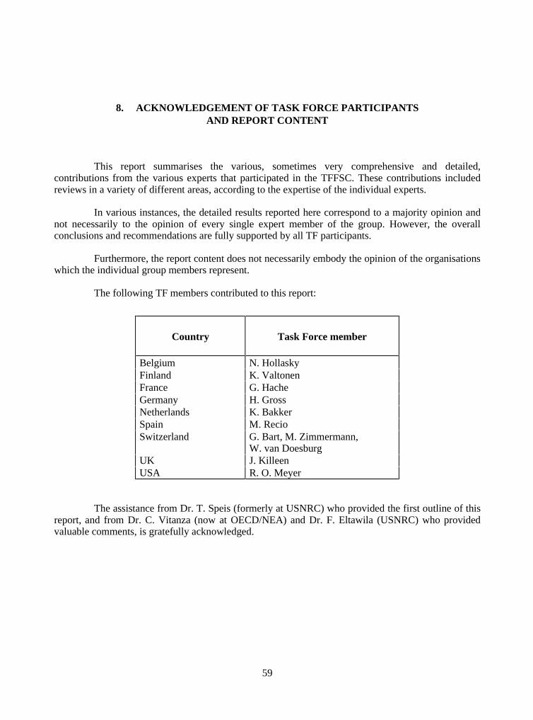
59
8. ACKNOWLEDGEMENT OF TASK FORCE PARTICIPANTSAND REPORT CONTENT
This report summarises the various, sometimes very comprehensive and detailed,contributions from the various experts that participated in the TFFSC. These contributions includedreviews in a variety of different areas, according to the expertise of the individual experts.
In various instances, the detailed results reported here correspond to a majority opinion andnot necessarily to the opinion of every single expert member of the group. However, the overallconclusions and recommendations are fully supported by all TF participants.
Furthermore, the report content does not necessarily embody the opinion of the organisationswhich the individual group members represent.
The following TF members contributed to this report:
Country Task Force member
Belgium N. HollaskyFinland K. ValtonenFrance G. HacheGermany H. GrossNetherlands K. BakkerSpain M. RecioSwitzerland G. Bart, M. Zimmermann,
W. van DoesburgUK J. KilleenUSA R. O. Meyer
The assistance from Dr. T. Speis (formerly at USNRC) who provided the first outline of thisreport, and from Dr. C. Vitanza (now at OECD/NEA) and Dr. F. Eltawila (USNRC) who providedvaluable comments, is gratefully acknowledged.

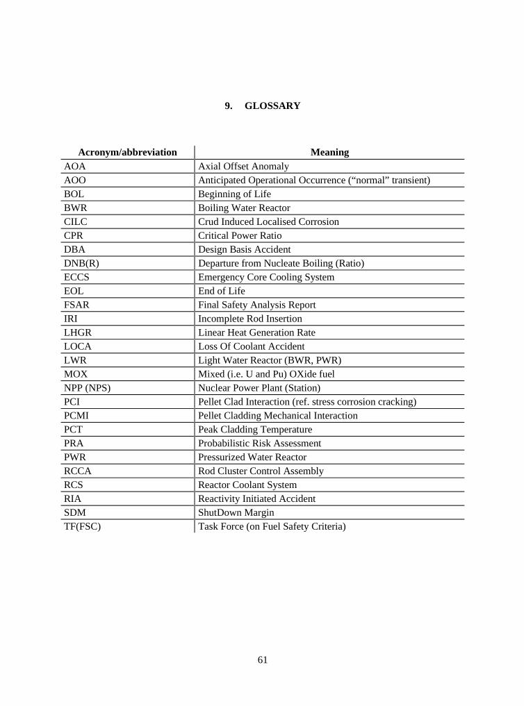
61
9. GLOSSARY
Acronym/abbreviation MeaningAOA Axial Offset AnomalyAOO Anticipated Operational Occurrence (“normal” transient)BOL Beginning of LifeBWR Boiling Water ReactorCILC Crud Induced Localised CorrosionCPR Critical Power RatioDBA Design Basis AccidentDNB(R) Departure from Nucleate Boiling (Ratio)ECCS Emergency Core Cooling SystemEOL End of LifeFSAR Final Safety Analysis ReportIRI Incomplete Rod InsertionLHGR Linear Heat Generation RateLOCA Loss Of Coolant AccidentLWR Light Water Reactor (BWR, PWR)MOX Mixed (i.e. U and Pu) OXide fuelNPP (NPS) Nuclear Power Plant (Station)PCI Pellet Clad Interaction (ref. stress corrosion cracking)PCMI Pellet Cladding Mechanical InteractionPCT Peak Cladding TemperaturePRA Probabilistic Risk AssessmentPWR Pressurized Water ReactorRCCA Rod Cluster Control AssemblyRCS Reactor Coolant SystemRIA Reactivity Initiated AccidentSDM ShutDown MarginTF(FSC) Task Force (on Fuel Safety Criteria)

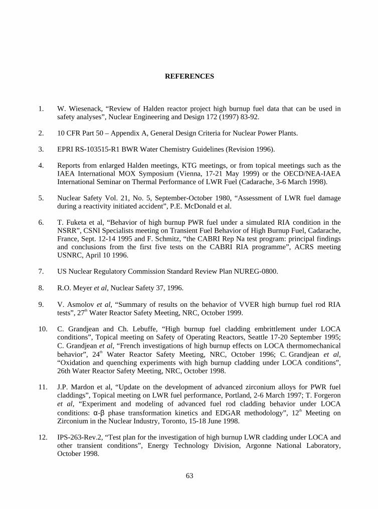
63
REFERENCES
1. W. Wiesenack, “Review of Halden reactor project high burnup fuel data that can be used insafety analyses”, Nuclear Engineering and Design 172 (1997) 83-92.
2. 10 CFR Part 50 – Appendix A, General Design Criteria for Nuclear Power Plants.
3. EPRI RS-103515-R1 BWR Water Chemistry Guidelines (Revision 1996).
4. Reports from enlarged Halden meetings, KTG meetings, or from topical meetings such as theIAEA International MOX Symposium (Vienna, 17-21 May 1999) or the OECD/NEA-IAEAInternational Seminar on Thermal Performance of LWR Fuel (Cadarache, 3-6 March 1998).
5. Nuclear Safety Vol. 21, No. 5, September-October 1980, “Assessment of LWR fuel damageduring a reactivity initiated accident”, P.E. McDonald et al.
6. T. Fuketa et al, “Behavior of high burnup PWR fuel under a simulated RIA condition in theNSRR”, CSNI Specialists meeting on Transient Fuel Behavior of High Burnup Fuel, Cadarache,France, Sept. 12-14 1995 and F. Schmitz, “the CABRI Rep Na test program: principal findingsand conclusions from the first five tests on the CABRI RIA programme”, ACRS meetingUSNRC, April 10 1996.
7. US Nuclear Regulatory Commission Standard Review Plan NUREG-0800.
8. R.O. Meyer et al, Nuclear Safety 37, 1996.
9. V. Asmolov et al, “Summary of results on the behavior of VVER high burnup fuel rod RIAtests”, 27th Water Reactor Safety Meeting, NRC, October 1999.
10. C. Grandjean and Ch. Lebuffe, “High burnup fuel cladding embrittlement under LOCAconditions”, Topical meeting on Safety of Operating Reactors, Seattle 17-20 September 1995;C. Grandjean et al, “French investigations of high burnup effects on LOCA thermomechanicalbehavior”, 24th Water Reactor Safety Meeting, NRC, October 1996; C. Grandjean et al,“Oxidation and quenching experiments with high burnup cladding under LOCA conditions”,26th Water Reactor Safety Meeting, NRC, October 1998.
11. J.P. Mardon et al, “Update on the development of advanced zirconium alloys for PWR fuelcladdings”, Topical meeting on LWR fuel performance, Portland, 2-6 March 1997; T. Forgeronet al, “Experiment and modeling of advanced fuel rod cladding behavior under LOCAconditions: α-β phase transformation kinetics and EDGAR methodology”, 12th Meeting onZirconium in the Nuclear Industry, Toronto, 15-18 June 1998.
12. IPS-263-Rev.2, “Test plan for the investigation of high burnup LWR cladding under LOCA andother transient conditions”, Energy Technology Division, Argonne National Laboratory,October 1998.
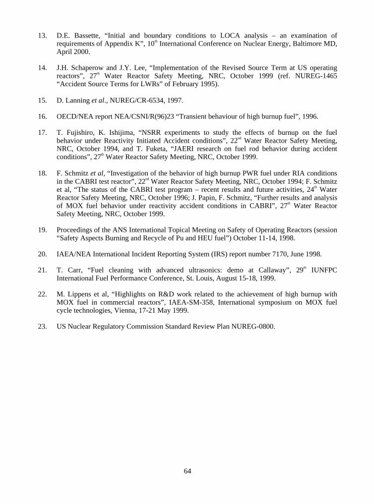
64
13. D.E. Bassette, “Initial and boundary conditions to LOCA analysis – an examination ofrequirements of Appendix K”, 10th International Conference on Nuclear Energy, Baltimore MD,April 2000.
14. J.H. Schaperow and J.Y. Lee, “Implementation of the Revised Source Term at US operatingreactors”, 27th Water Reactor Safety Meeting, NRC, October 1999 (ref. NUREG-1465“Accident Source Terms for LWRs” of February 1995).
15. D. Lanning et al., NUREG/CR-6534, 1997.
16. OECD/NEA report NEA/CSNI/R(96)23 “Transient behaviour of high burnup fuel”, 1996.
17. T. Fujishiro, K. Ishijima, “NSRR experiments to study the effects of burnup on the fuelbehavior under Reactivity Initiated Accident conditions”, 22nd Water Reactor Safety Meeting,NRC, October 1994, and T. Fuketa, “JAERI research on fuel rod behavior during accidentconditions”, 27th Water Reactor Safety Meeting, NRC, October 1999.
18. F. Schmitz et al, “Investigation of the behavior of high burnup PWR fuel under RIA conditionsin the CABRI test reactor”, 22nd Water Reactor Safety Meeting, NRC, October 1994; F. Schmitzet al, “The status of the CABRI test program – recent results and future activities, 24th WaterReactor Safety Meeting, NRC, October 1996; J. Papin, F. Schmitz, “Further results and analysisof MOX fuel behavior under reactivity accident conditions in CABRI”, 27th Water ReactorSafety Meeting, NRC, October 1999.
19. Proceedings of the ANS International Topical Meeting on Safety of Operating Reactors (session“Safety Aspects Burning and Recycle of Pu and HEU fuel”) October 11-14, 1998.
20. IAEA/NEA International Incident Reporting System (IRS) report number 7170, June 1998.
21. T. Carr, “Fuel cleaning with advanced ultrasonics: demo at Callaway”, 29th IUNFPCInternational Fuel Performance Conference, St. Louis, August 15-18, 1999.
22. M. Lippens et al, “Highlights on R&D work related to the achievement of high burnup withMOX fuel in commercial reactors”, IAEA-SM-358, International symposium on MOX fuelcycle technologies, Vienna, 17-21 May 1999.
23. US Nuclear Regulatory Commission Standard Review Plan NUREG-0800.
ALSO AVAILABLE
NEA Publications of General Interest2000 Annual Report (2001) Free: paper or web.
NEA NewsISSN 1605-9581 Yearly subscription: 37 US$ 45 GBP 26 ¥ 4 800
Geologic Disposal of Radioactive Waste in Perspective (2000)ISBN 92-64-18425-2 Price: 20 US$ 20 GBP 12 ¥ 2 050
Radioactive Waste Management Programmes in OECD/NEA Member countries (1998)ISBN 92-64-16033-7 Price: 32 US$ 33 GBP 20 ¥ 4 150
Safety
Investing in Trust: Nuclear Regulators and the Public (2001)ISBN 92-64-19314-6 Price: 60 US$ 54 GBP 37 ¥ 6 050
Assuring Nuclear Safety Competence into the 21st Century (2000)ISBN 92-64-18517-8 Price: 55 US$ 50 GBP 31 ¥ 5 300
Nuclear Safety Research in OECD Countries – Major Facilities and Programmes at Risk (2001)ISBN 92-64-18468-6 Free: paper or Web.
Nuclear Safety Research in OECD Countries – Summary Report of Major Facilities and Programmes at Risk(2001)ISBN 92-64-18463-5 Free: paper or Web.
Collective Statement on the Role of Research in a Nuclear Regulatory Context (2001)Bilingual Free: paper or Web.
Assuring Future Nuclear Safety Competencies – Specific Actions (2001)ISBN 92-64-18462-7 Free: paper or Web.
Improving Nuclear Regulatory Effectiveness (2001)ISBN 92-64-18465-1 Free: paper or Web.
Nuclear Regulatory Challenges Arising from Competition in Electricity Markets (2001)Bilingual.ISBN 92-64-08460-6 Free: paper or Web.
Nuclear Power Plant Operating Experiences from the IAEA/NEA Incident Reporting System1996-1999 (2000)ISBN 92-64-17671-3 Free: paper or Web.
Regulatory Response Strategies for Safety Culture Problems (2000)Bilingual.ISBN 92-64-07672-7 Free: paper or Web.
The Role of the Nuclear Regulator in Promoting and Evaluating Safety Culture (1999)Bilingual. Free: paper or Web.
Order form on reverse side.

ORDER FORM
OECD Nuclear Energy Agency, 12 boulevard des Iles, F-92130 Issy-les-Moulineaux, FranceTel. 33 (0)1 45 24 10 15; Fax 33 (0)1 45 24 11 10; E-mail: [email protected]; Internet: http://www.nea.fr
Q Title ISBN Price Am
Total
❑ Payment enclosed (cheque or money order payable to OECD Publications).
Charge my credit card ❑ VISA ❑ Mastercard ❑ American Express
(Prices include postage and handling fees)
Card No. Expiration date Signature
Name
Address Country
Telephone Fax
The NEA wishes to express its gratitude to the Government of Japanfor facilitating the production of this report.

OECD PUBLICATIONS, 2, rue André-Pascal, 75775 PARIS CEDEX 16
PRINTED IN FRANCE
(66 2001 17 1 P) ISBN 92-64-19687-0 – No. 52291 2001