Embed Size (px)
Citation preview
Professor Gareth B. NeighbourCEng CPhys MInstP MIMMM FHEA PGCHE
Head of Department
Department of Mechanical Engineering and Mathematical Sciences
Editor: CARBON (Elsevier), Impact Factor 6.196
UTC Swindon Governor / Director
Chair: UK Graphite Core Committee
Nuclear Graphite:
Past and Future Perspectives
My Perspective!!!
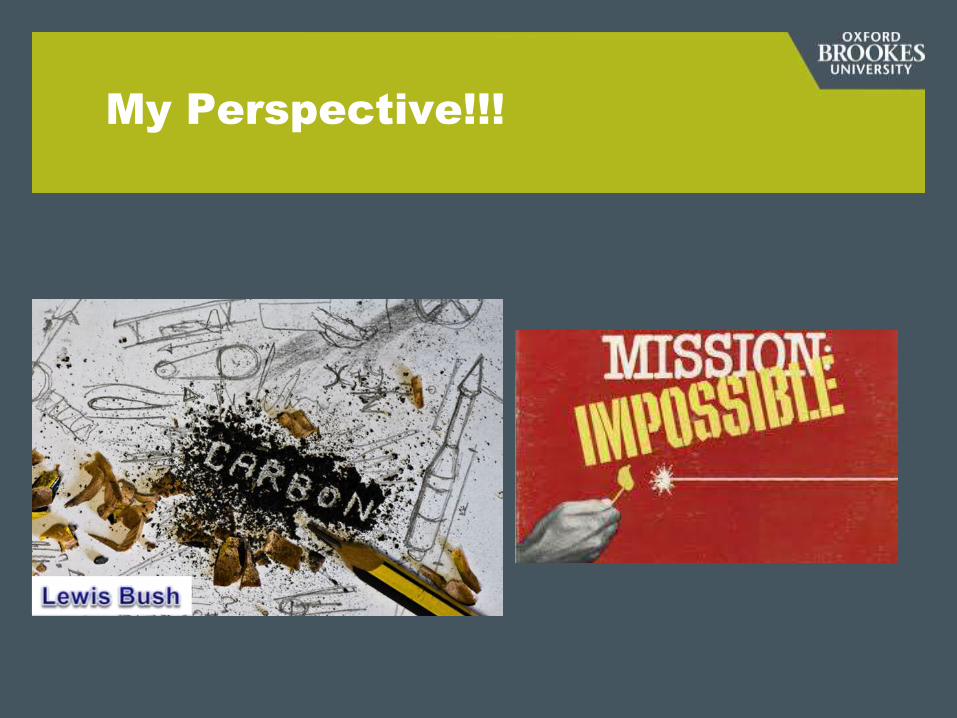
A View of the Carbon World
Tiny!

A Not So Short History
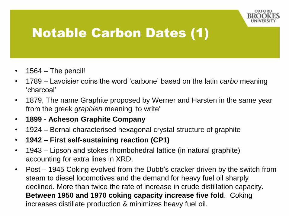
Notable Carbon Dates (1)
• 1564 – The pencil!
• 1789 – Lavoisier coins the word ‘carbone’ based on the latin carbo meaning
‘charcoal’
• 1879, The name Graphite proposed by Werner and Harsten in the same year
from the greek graphien meaning ‘to write’
• 1899 - Acheson Graphite Company
• 1924 – Bernal characterised hexagonal crystal structure of graphite
• 1942 – First self-sustaining reaction (CP1)
• 1943 – Lipson and stokes rhombohedral lattice (in natural graphite)
accounting for extra lines in XRD.
• Post – 1945 Coking evolved from the Dubb’s cracker driven by the switch from
steam to diesel locomotives and the demand for heavy fuel oil sharply
declined. More than twice the rate of increase in crude distillation capacity.
Between 1950 and 1970 coking capacity increase five fold. Coking
increases distillate production & minimizes heavy fuel oil.
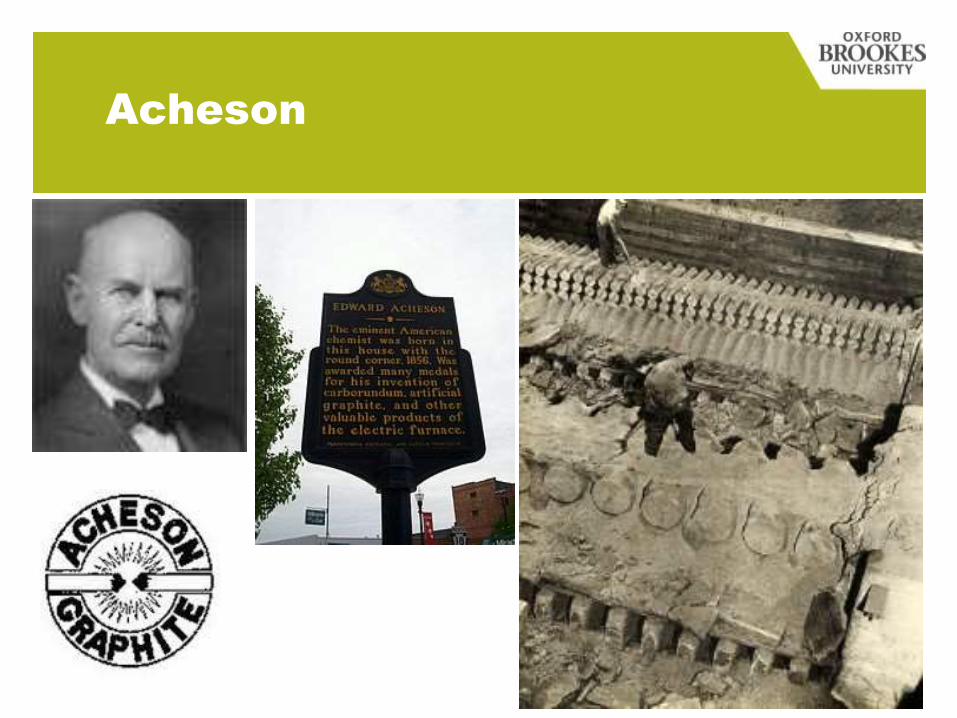
Acheson
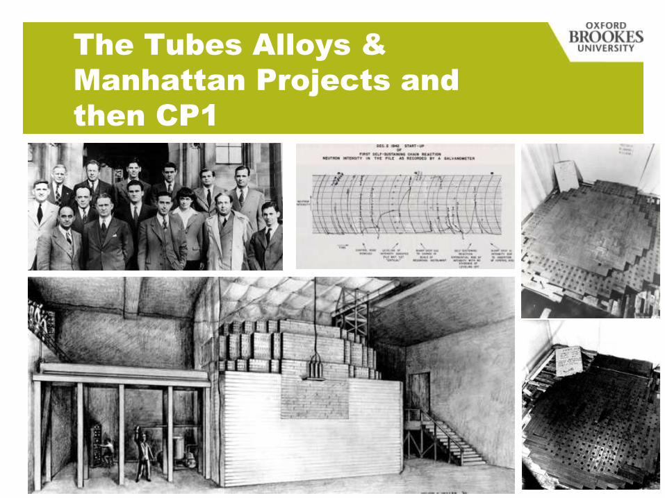
The Tubes Alloys &
Manhattan Projects and
then CP1
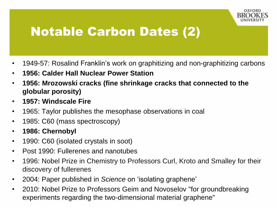
Notable Carbon Dates (2)
• 1949-57: Rosalind Franklin’s work on graphitizing and non-graphitizing carbons
• 1956: Calder Hall Nuclear Power Station
• 1956: Mrozowski cracks (fine shrinkage cracks that connected to the
globular porosity)
• 1957: Windscale Fire
• 1965: Taylor publishes the mesophase observations in coal
• 1985: C60 (mass spectroscopy)
• 1986: Chernobyl
• 1990: C60 (isolated crystals in soot)
• Post 1990: Fullerenes and nanotubes
• 1996: Nobel Prize in Chemistry to Professors Curl, Kroto and Smalley for their
discovery of fullerenes
• 2004: Paper published in Science on ‘isolating graphene’
• 2010: Nobel Prize to Professors Geim and Novoselov "for groundbreaking
experiments regarding the two-dimensional material graphene"
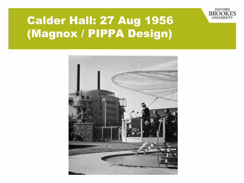
Calder Hall: 27 Aug 1956
(Magnox / PIPPA Design)
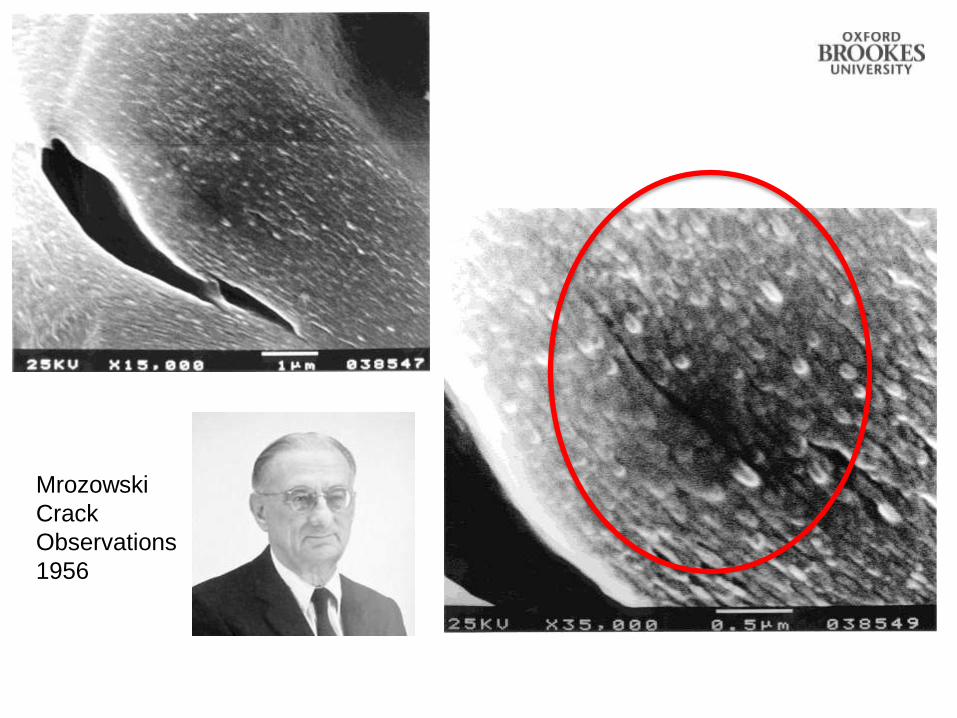
Mrozowski
Crack
Observations
1956
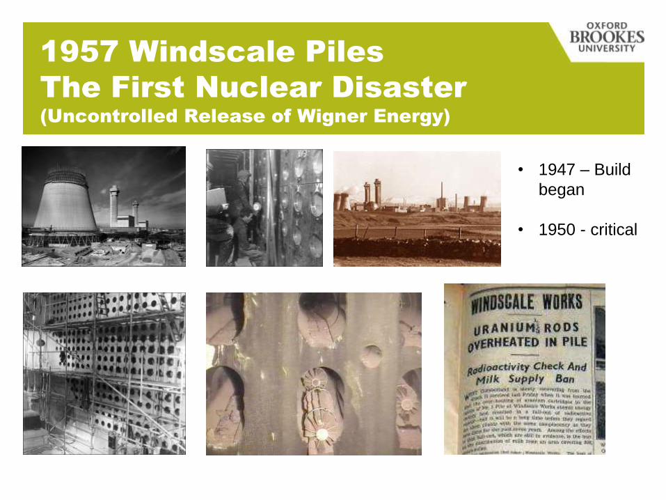
1957 Windscale Piles
The First Nuclear Disaster
(Uncontrolled Release of Wigner Energy)
• 1947 – Build
began
• 1950 - critical
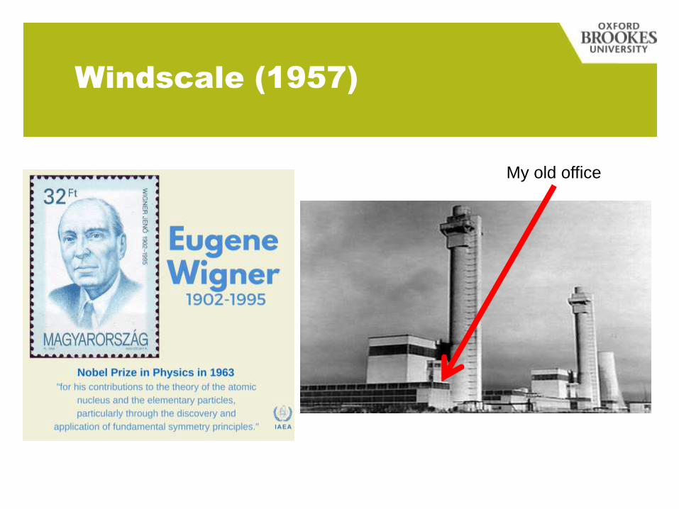
Windscale (1957)
My old office
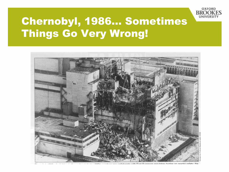
Chernobyl, 1986… Sometimes
Things Go Very Wrong!
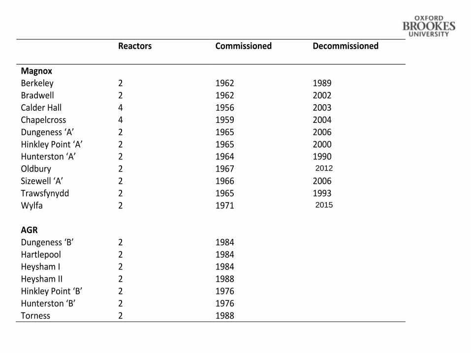
Reactors Commissioned Decommissioned
Magnox Berkeley 2 1962 1989 Bradwell 2 1962 2002 Calder Hall 4 1956 2003 Chapelcross 4 1959 2004 Dungeness ‘A’ 2 1965 2006 Hinkley Point ‘A’ 2 1965 2000 Hunterston ‘A’ 2 1964 1990 Oldbury 2 1967 Sizewell ‘A’ 2 1966 2006 Trawsfynydd 2 1965 1993 Wylfa 2 1971 AGR Dungeness ‘B’ 2 1984 Hartlepool 2 1984 Heysham I 2 1984 Heysham II 2 1988 Hinkley Point ‘B’ 2 1976 Hunterston ‘B’ 2 1976 Torness 2 1988
2015
2012
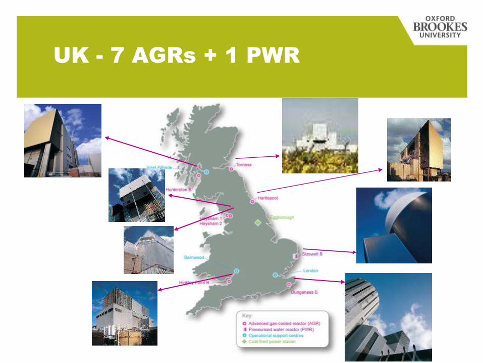
UK - 7 AGRs + 1 PWR

Advanced Gas-cooled
Reactor (AGR)
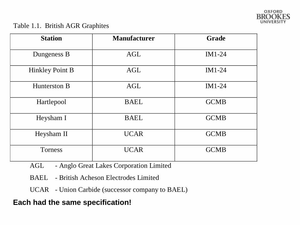
Table 1.1. British AGR Graphites
Station Manufacturer Grade
Dungeness B AGL IM1-24
Hinkley Point B AGL IM1-24
Hunterston B AGL IM1-24
Hartlepool BAEL GCMB
Heysham I BAEL GCMB
Heysham II UCAR GCMB
Torness UCAR GCMB
AGL - Anglo Great Lakes Corporation Limited
BAEL - British Acheson Electrodes Limited
UCAR - Union Carbide (successor company to BAEL)
Each had the same specification!
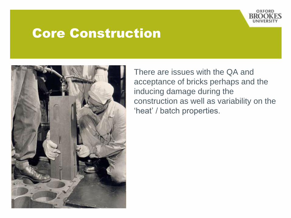
Core Construction
There are issues with the QA and
acceptance of bricks perhaps and the
inducing damage during the
construction as well as variability on the
‘heat’ / batch properties.
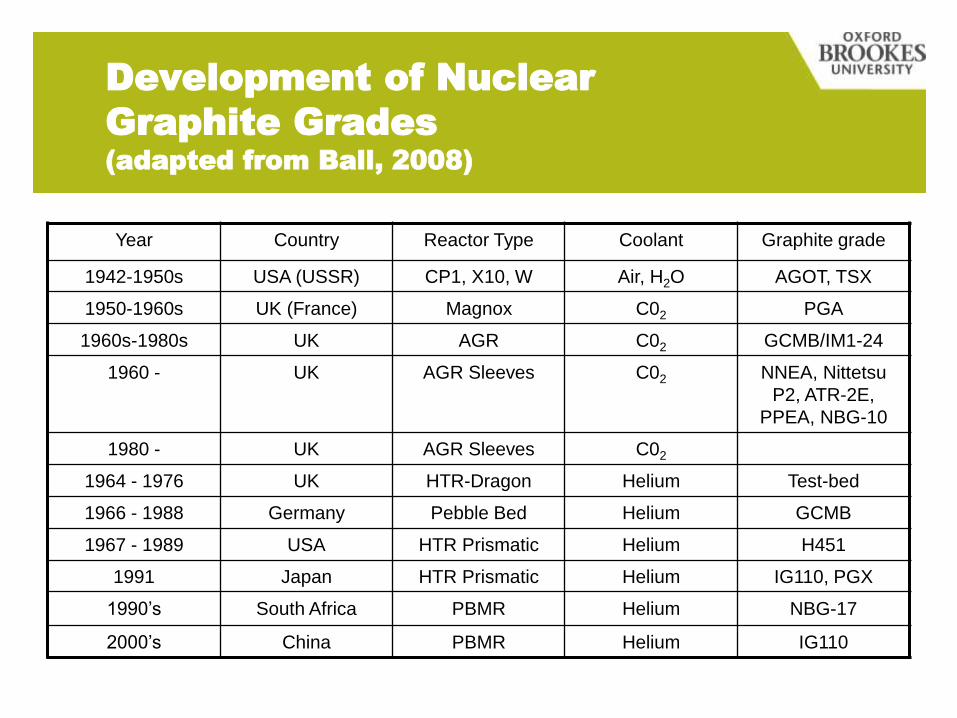
Development of Nuclear
Graphite Grades
(adapted from Ball, 2008)
Year Country Reactor Type Coolant Graphite grade
1942-1950s USA (USSR) CP1, X10, W Air, H2O AGOT, TSX
1950-1960s UK (France) Magnox C02 PGA
1960s-1980s UK AGR C02 GCMB/IM1-24
1960 - UK AGR Sleeves C02 NNEA, Nittetsu
P2, ATR-2E,
PPEA, NBG-10
1980 - UK AGR Sleeves C02
1964 - 1976 UK HTR-Dragon Helium Test-bed
1966 - 1988 Germany Pebble Bed Helium GCMB
1967 - 1989 USA HTR Prismatic Helium H451
1991 Japan HTR Prismatic Helium IG110, PGX
1990’s South Africa PBMR Helium NBG-17
2000’s China PBMR Helium IG110
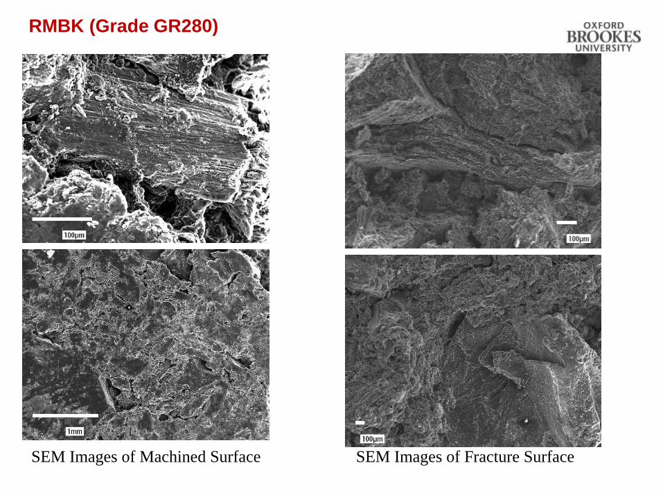
SEM Images of Machined Surface SEM Images of Fracture Surface
RMBK (Grade GR280)
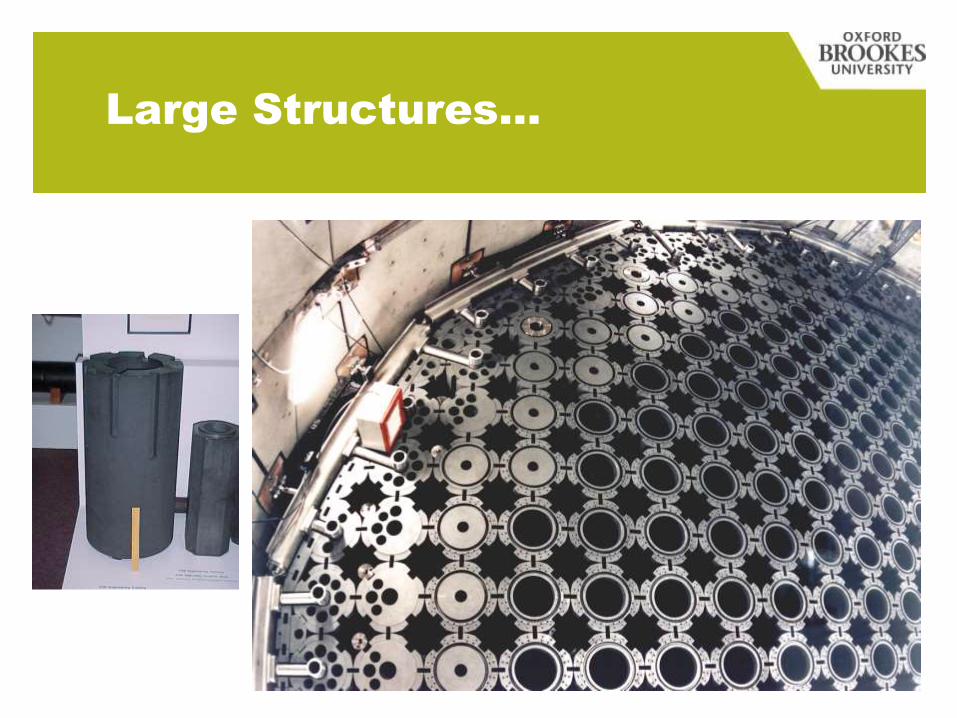
Large Structures…
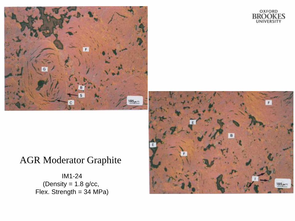
AGR Moderator Graphite
IM1-24
(Density = 1.8 g/cc,
Flex. Strength = 34 MPa)
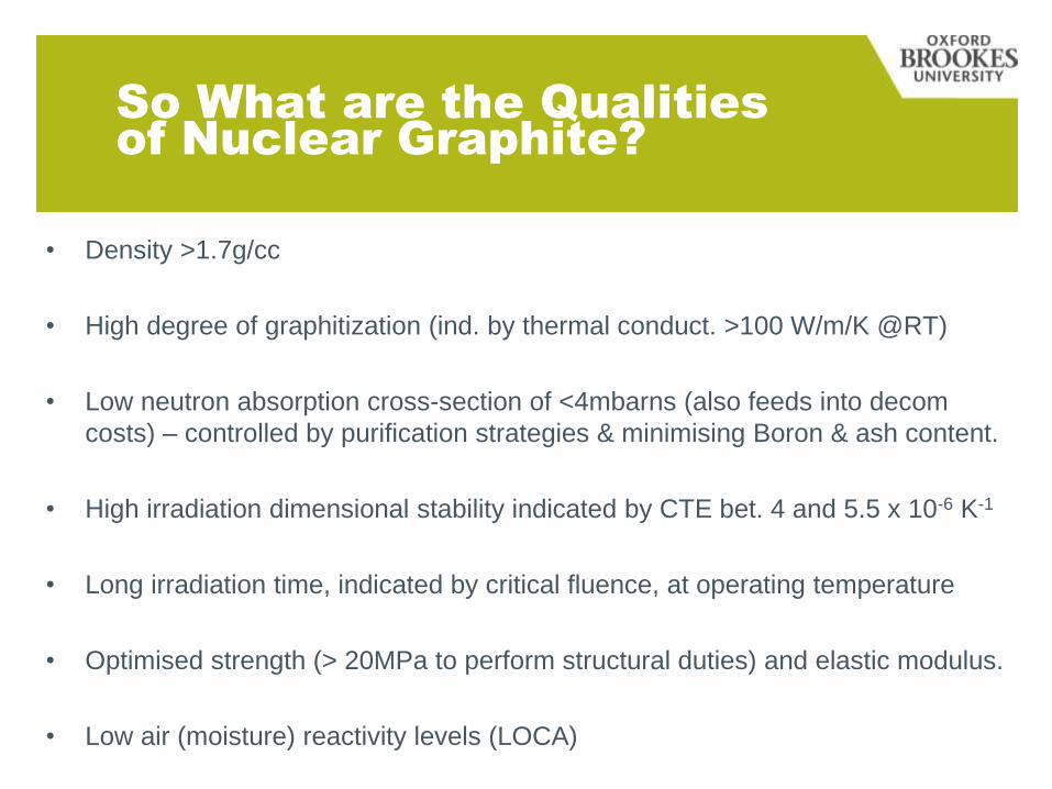
So What are the Qualities
of Nuclear Graphite?
• Density >1.7g/cc
• High degree of graphitization (ind. by thermal conduct. >100 W/m/K @RT)
• Low neutron absorption cross-section of <4mbarns (also feeds into decom
costs) – controlled by purification strategies & minimising Boron & ash content.
• High irradiation dimensional stability indicated by CTE bet. 4 and 5.5 x 10⁻⁶ K-1
• Long irradiation time, indicated by critical fluence, at operating temperature
• Optimised strength (> 20MPa to perform structural duties) and elastic modulus.
• Low air (moisture) reactivity levels (LOCA)
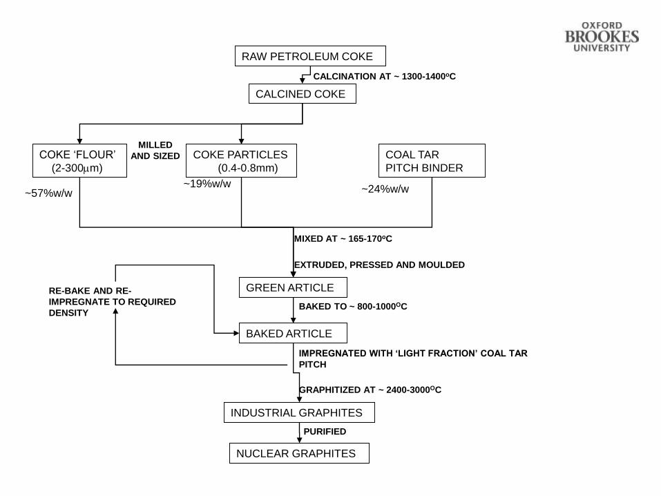
CALCINATION AT ~ 1300-1400oC
COKE ‘FLOUR’
(2-300m)
COKE PARTICLES
(0.4-0.8mm)
MILLED
AND SIZED COAL TAR
PITCH BINDER
MIXED AT ~ 165-170oC
EXTRUDED, PRESSED AND MOULDED
RAW PETROLEUM COKE
CALCINED COKE
NUCLEAR GRAPHITES
~57%w/w~19%w/w
~24%w/w
BAKED TO ~ 800-1000OC
IMPREGNATED WITH ‘LIGHT FRACTION’ COAL TAR
PITCH
GREEN ARTICLE
BAKED ARTICLE
GRAPHITIZED AT ~ 2400-3000OC
INDUSTRIAL GRAPHITES
RE-BAKE AND RE-
IMPREGNATE TO REQUIRED
DENSITY
PURIFIED
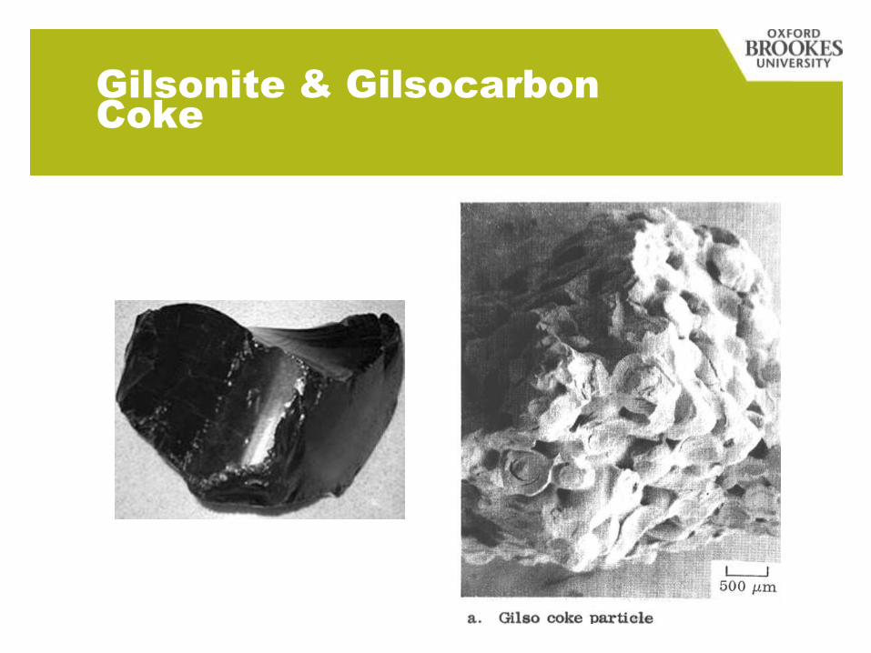
Gilsonite & Gilsocarbon
Coke
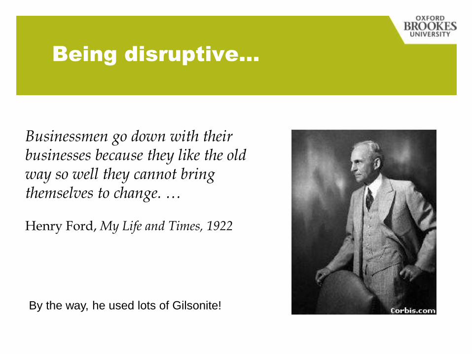
Businessmen go down with their businesses because they like the old way so well they cannot bring themselves to change. …
Henry Ford, My Life and Times, 1922
Being disruptive…
By the way, he used lots of Gilsonite!
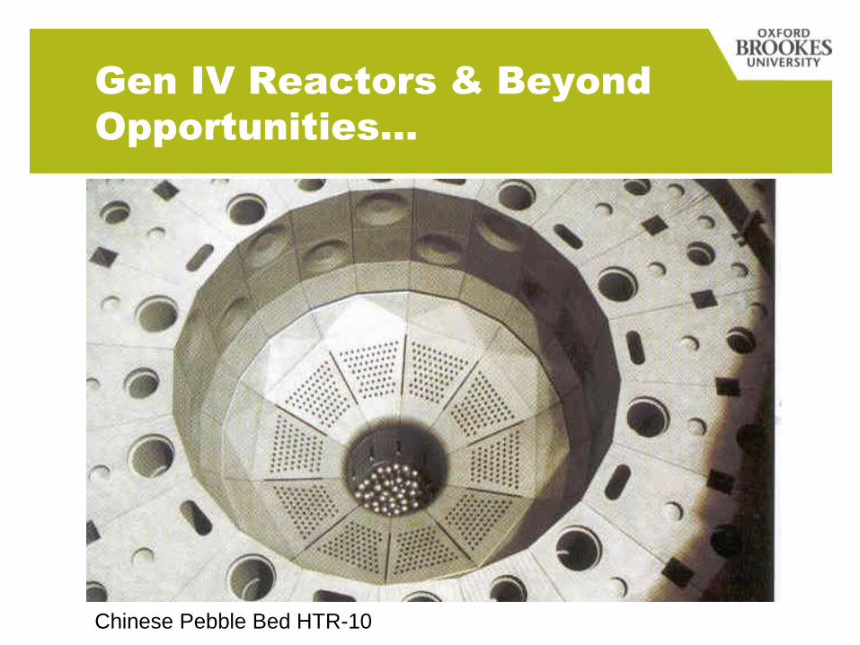
Gen IV Reactors & Beyond
Opportunities…
Chinese Pebble Bed HTR-10
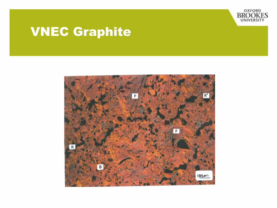
VNEC Graphite
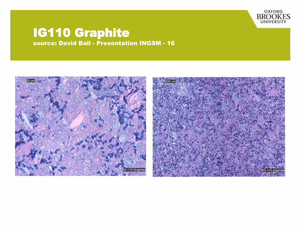
IG110 Graphite
source: David Ball - Presentation INGSM - 16
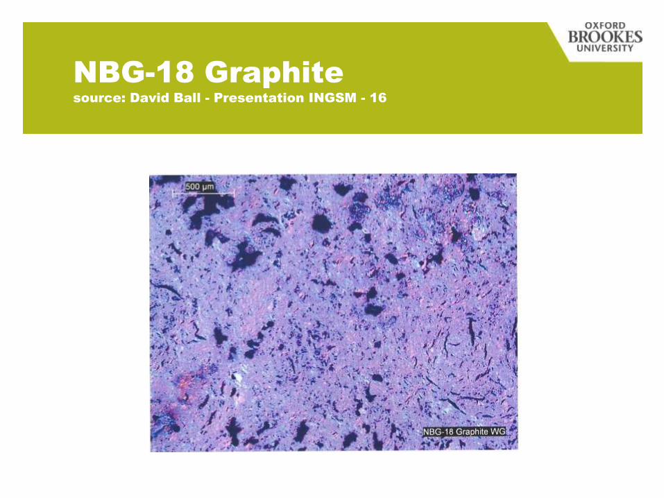
NBG-18 Graphite
source: David Ball - Presentation INGSM - 16
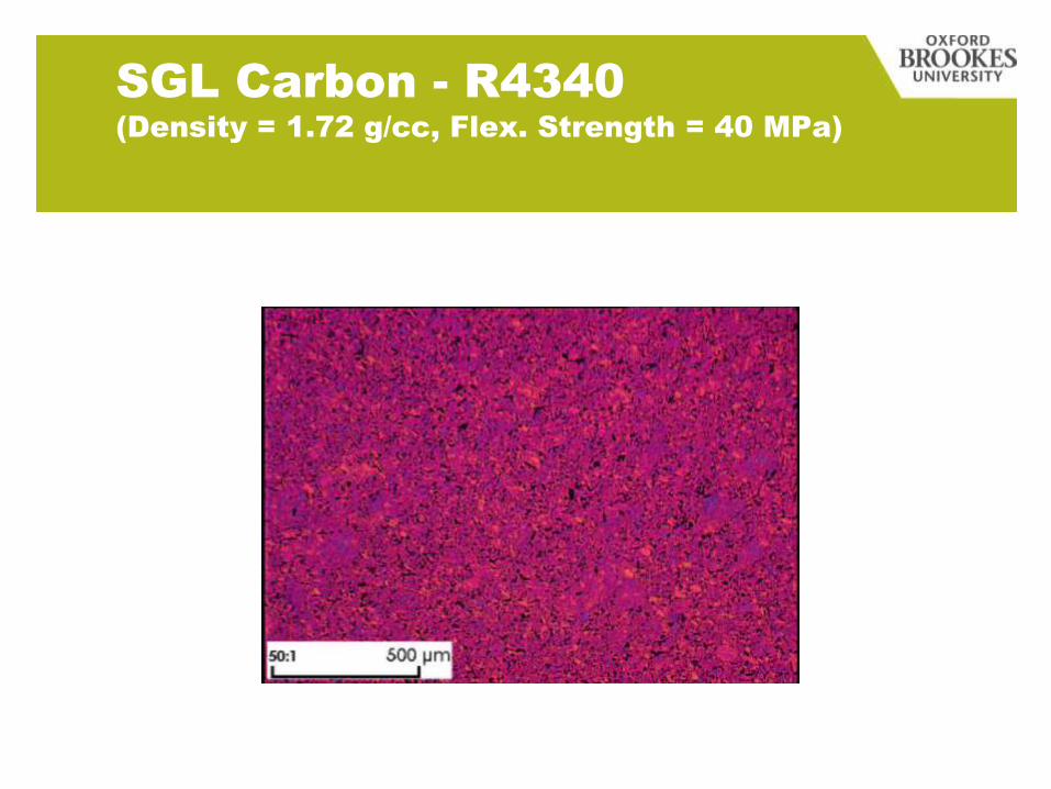
SGL Carbon - R4340
(Density = 1.72 g/cc, Flex. Strength = 40 MPa)

The Current Problem in the UK
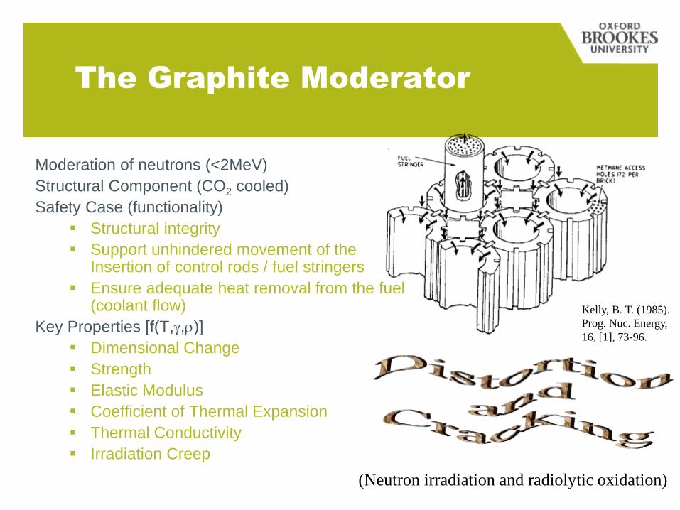
The Graphite Moderator
Moderation of neutrons (<2MeV)
Structural Component (CO2 cooled)
Safety Case (functionality)
Structural integrity
Support unhindered movement of theInsertion of control rods / fuel stringers
Ensure adequate heat removal from the fuel(coolant flow)
Key Properties [f(T,g,r)]
Dimensional Change
Strength
Elastic Modulus
Coefficient of Thermal Expansion
Thermal Conductivity
Irradiation Creep
Kelly, B. T. (1985).
Prog. Nuc. Energy,
16, [1], 73-96.
(Neutron irradiation and radiolytic oxidation)
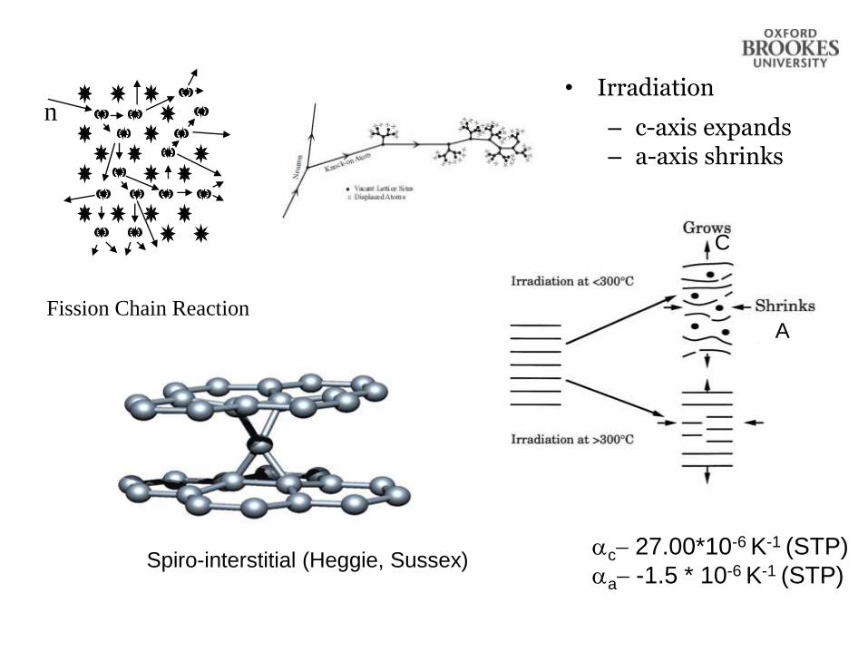
Fission Chain Reaction
n• Irradiation
– c-axis expands– a-axis shrinks
ac- 27.00*10-6 K-1 (STP)
aa- -1.5 * 10-6 K-1 (STP)
C
A
Spiro-interstitial (Heggie, Sussex)
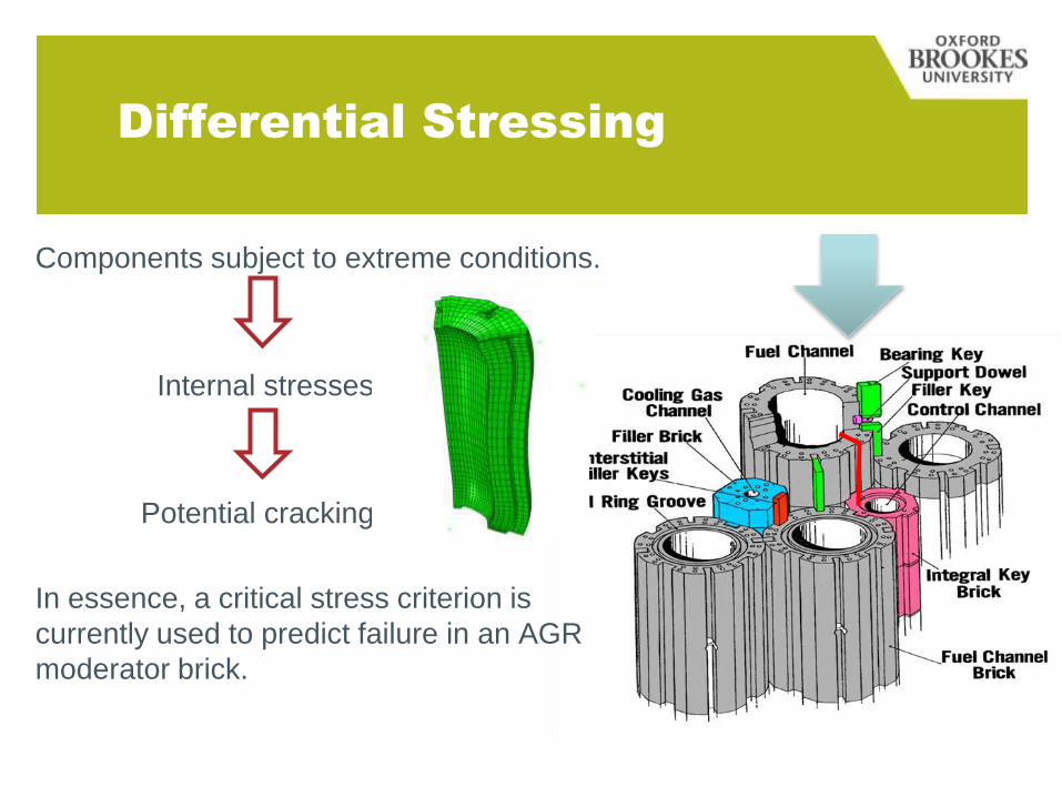
Differential Stressing
Components subject to extreme conditions.
Internal stresses
Potential cracking
In essence, a critical stress criterion is
currently used to predict failure in an AGR
moderator brick.
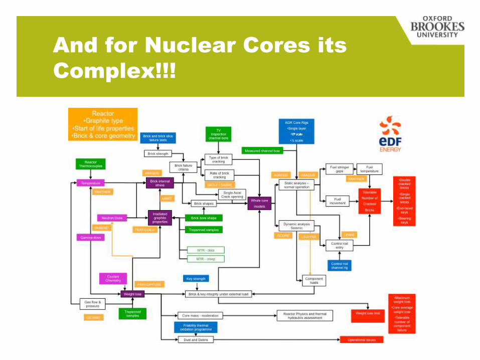
And for Nuclear Cores its
Complex!!!
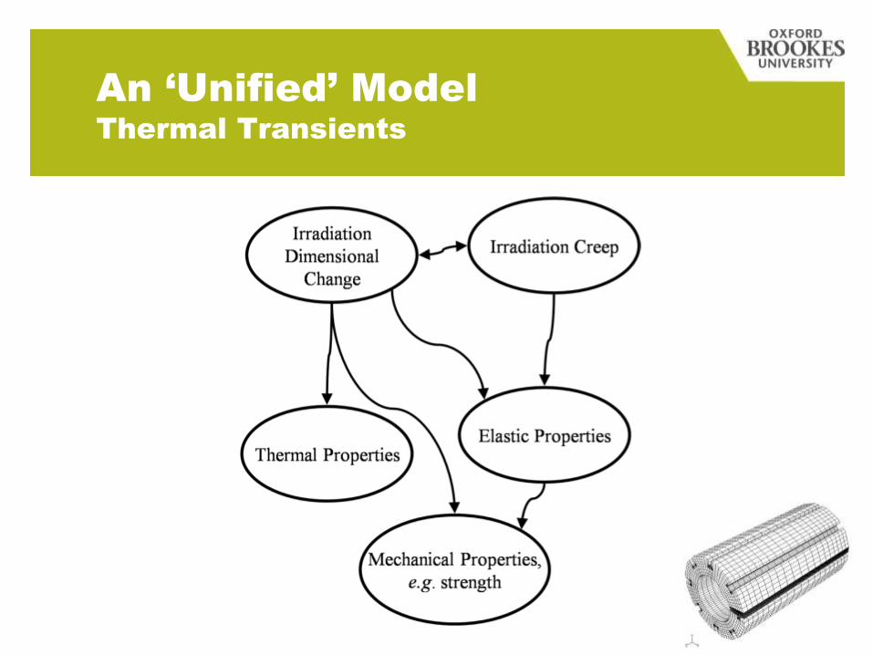
An ‘Unified’ Model
Thermal Transients
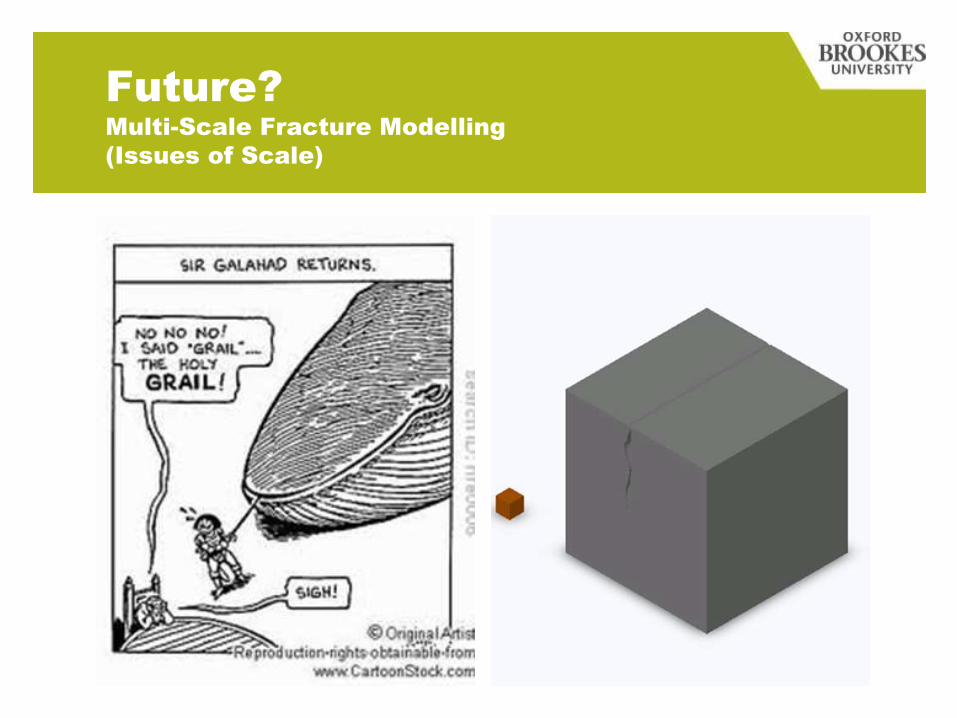
Future?
Multi-Scale Fracture Modelling
(Issues of Scale)
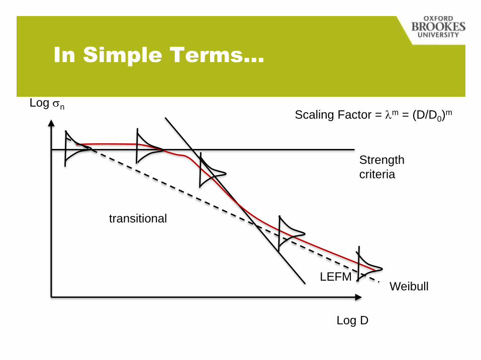
In Simple Terms…
Log sn
Log D
Strength
criteria
WeibullLEFM
transitional
Scaling Factor = lm = (D/D0)m
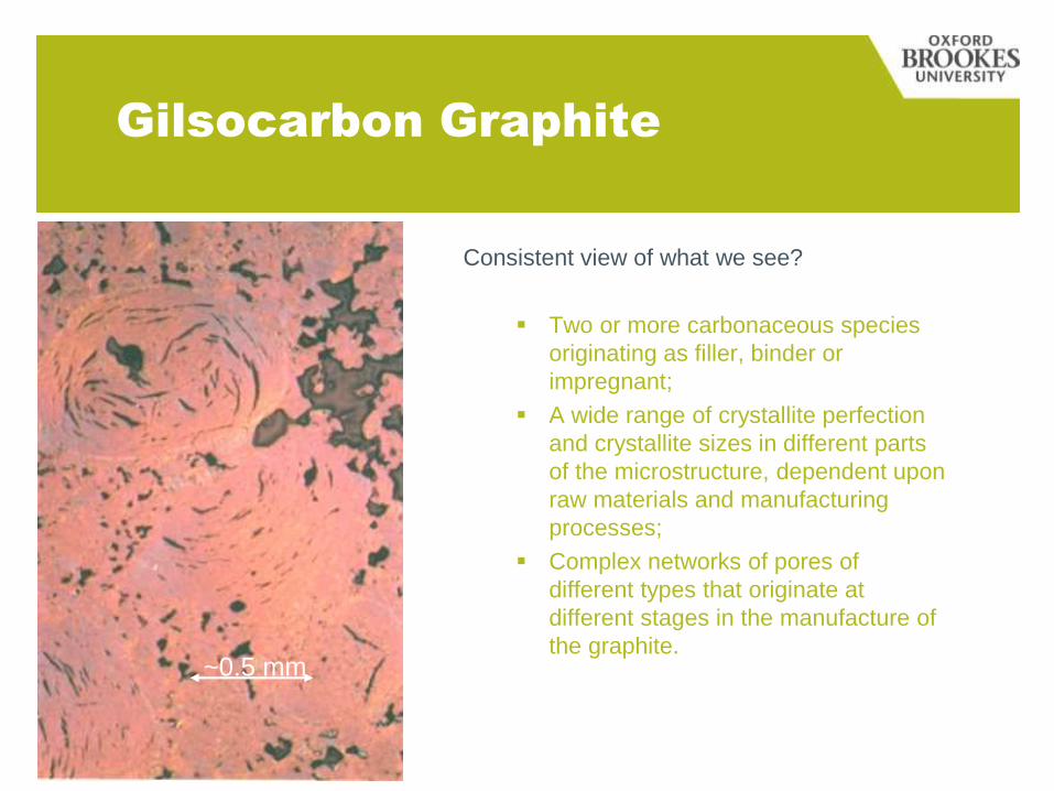
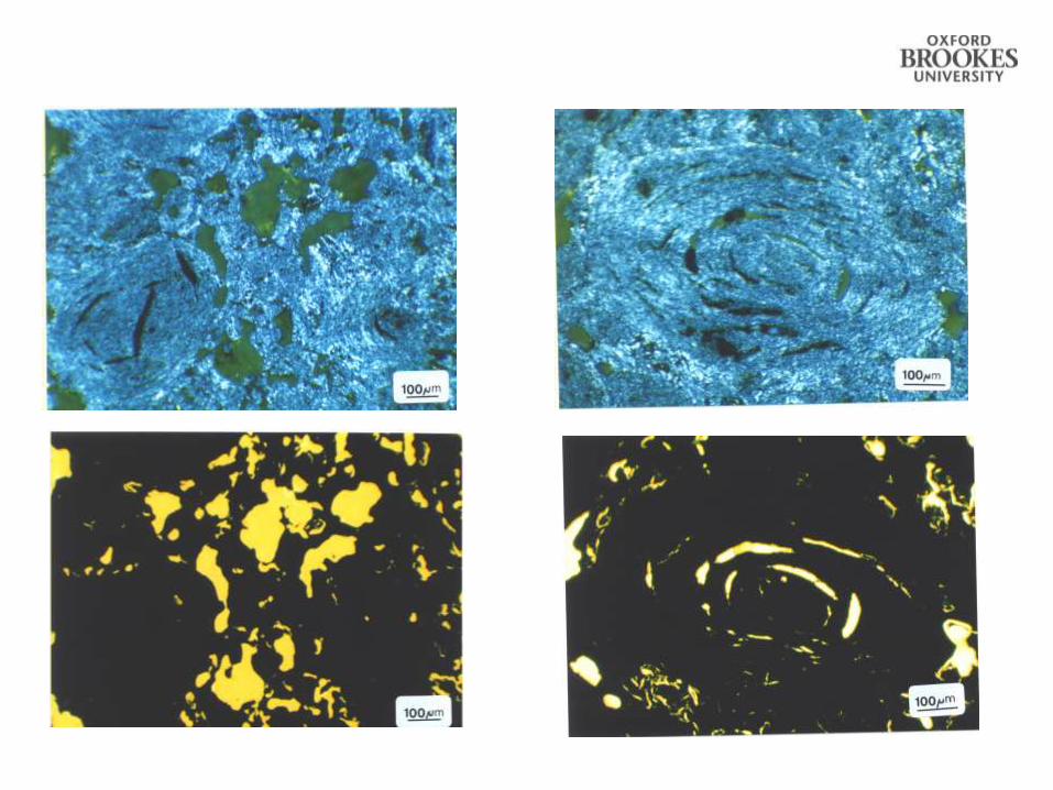
Gilsocarbon Graphite
Consistent view of what we see?
Two or more carbonaceous species
originating as filler, binder or
impregnant;
A wide range of crystallite perfection
and crystallite sizes in different parts
of the microstructure, dependent upon
raw materials and manufacturing
processes;
Complex networks of pores of
different types that originate at
different stages in the manufacture of
the graphite.~0.5 mm
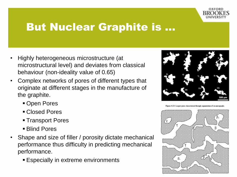
But Nuclear Graphite is …
• Highly heterogeneous microstructure (at
microstructural level) and deviates from classical
behaviour (non-ideality value of 0.65)
• Complex networks of pores of different types that
originate at different stages in the manufacture of
the graphite.
Open Pores
Closed Pores
Transport Pores
Blind Pores
• Shape and size of filler / porosity dictate mechanical
performance thus difficulty in predicting mechanical
performance.
Especially in extreme environments
r
r
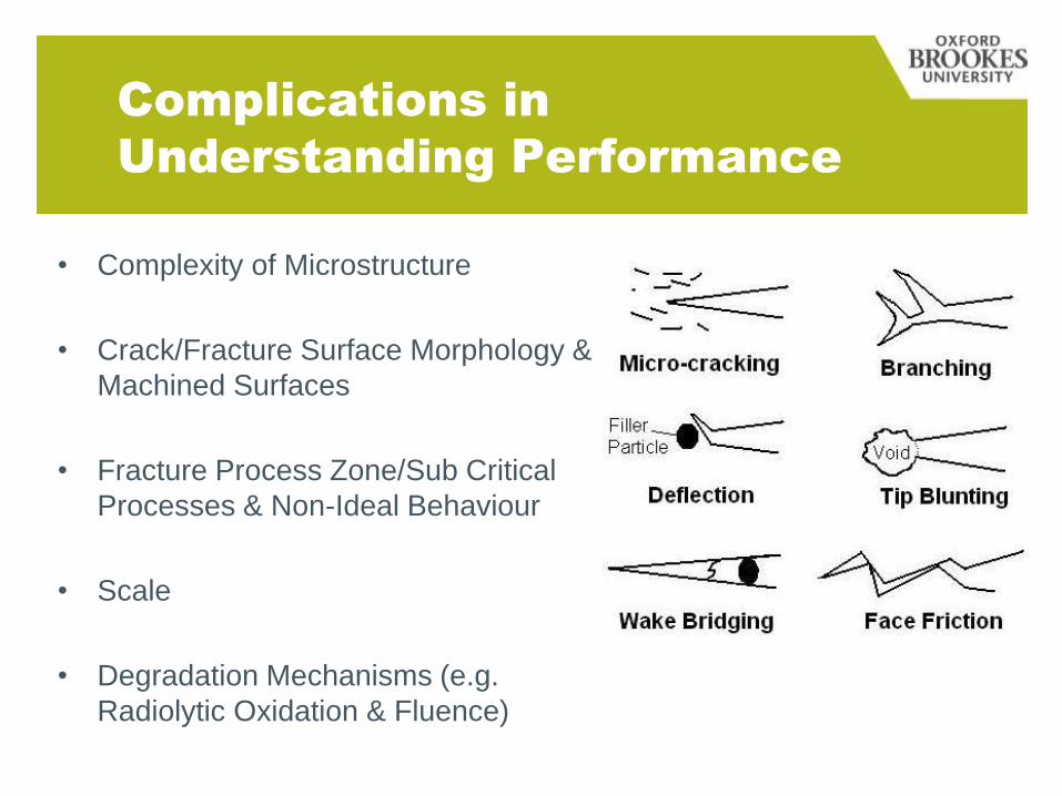
Complications in
Understanding Performance
• Complexity of Microstructure
• Crack/Fracture Surface Morphology &
Machined Surfaces
• Fracture Process Zone/Sub Critical
Processes & Non-Ideal Behaviour
• Scale
• Degradation Mechanisms (e.g.
Radiolytic Oxidation & Fluence)
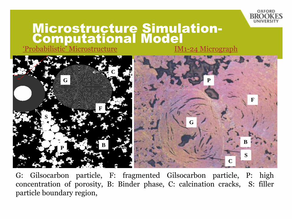
Microstructure Simulation-
Computational Model
G
F
B
S
C
P
G: Gilsocarbon particle, F: fragmented Gilsocarbon particle, P: highconcentration of porosity, B: Binder phase, C: calcination cracks, S: fillerparticle boundary region,
G
F
B
SC
P
‘Probabilistic’ Microstructure IM1-24 Micrograph
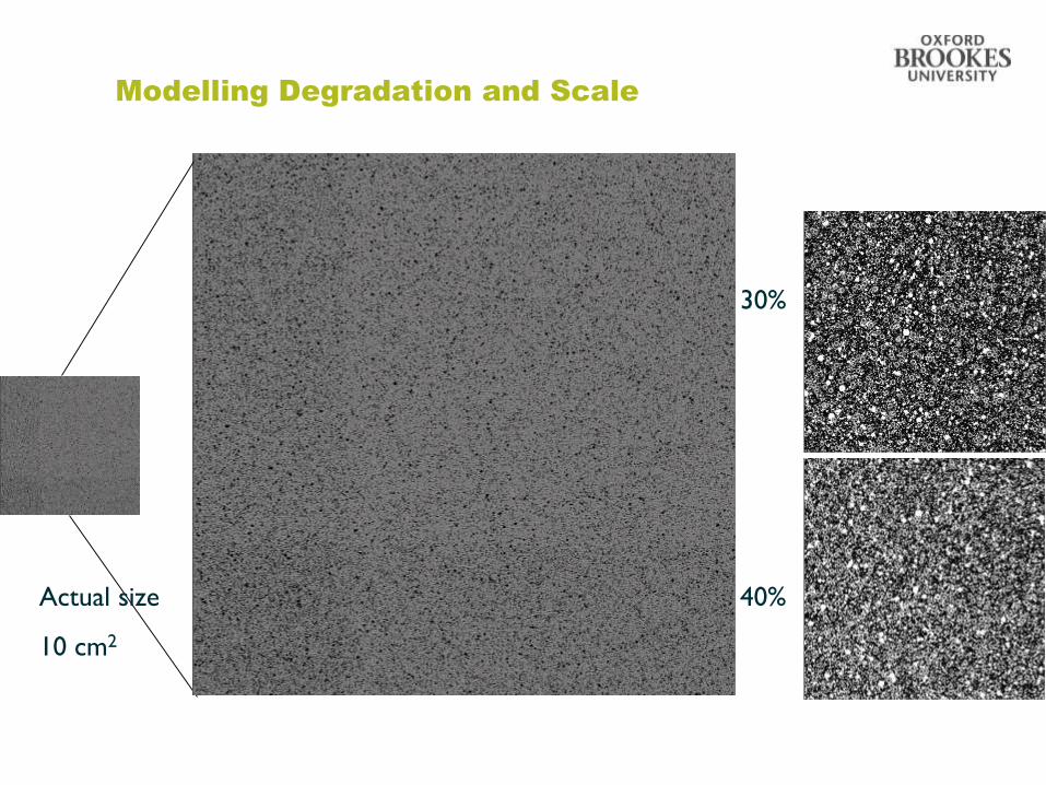
Modelling Degradation and Scale
Actual size
10 cm2
30%
40%
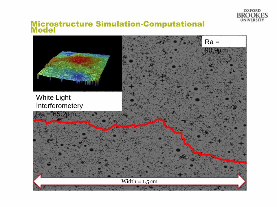
Microstructure Simulation-Computational
Model
Ra =
90.9m
White Light
Interferometery
Ra = 65.2m
Width = 1.5 cm
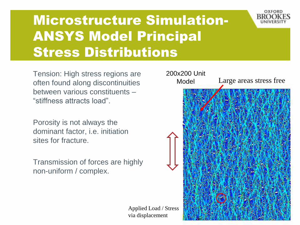
Microstructure Simulation-
ANSYS Model Principal
Stress Distributions
200x200 Unit
Model
Applied Load / Stress
via displacement
Large areas stress freeTension: High stress regions are
often found along discontinuities
between various constituents –
“stiffness attracts load”.
Porosity is not always the
dominant factor, i.e. initiation
sites for fracture.
Transmission of forces are highly
non-uniform / complex.
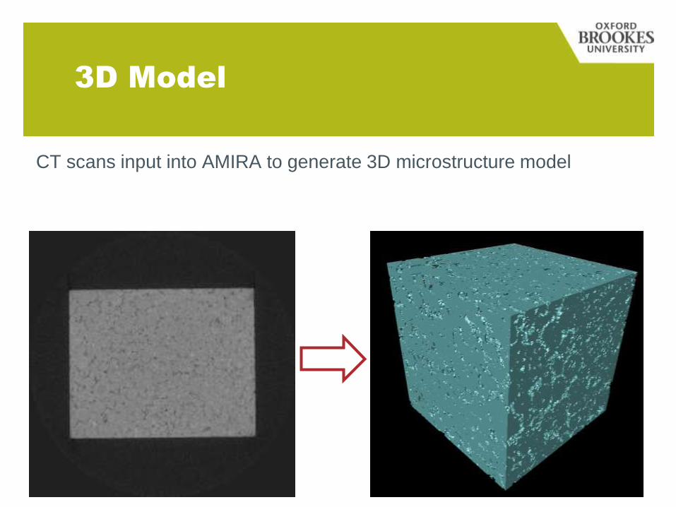
3D Model
CT scans input into AMIRA to generate 3D microstructure model
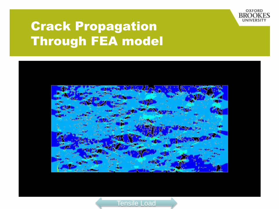
Crack Propagation
Through FEA model
Tensile Load
0
200
400
600
800
1000
1200
1400
1600
0 0.05 0.1 0.15 0.2 0.25 0.3
Load
(N
)
Load-Point Displacement (mm)
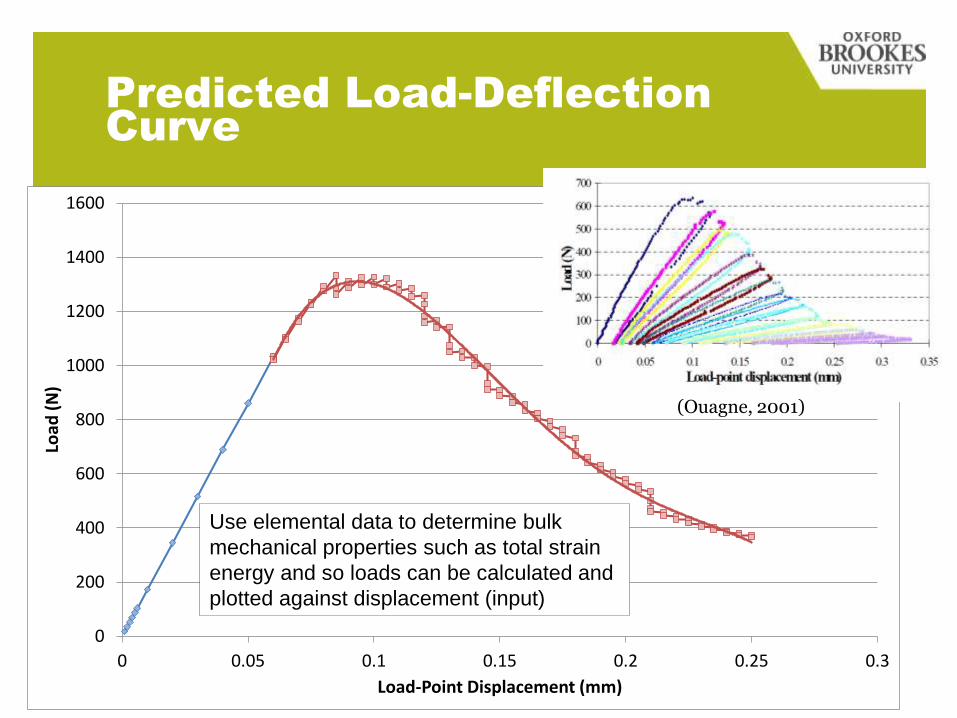
Predicted Load-Deflection
Curve
(Ouagne, 2001)
Use elemental data to determine bulk
mechanical properties such as total strain
energy and so loads can be calculated and
plotted against displacement (input)
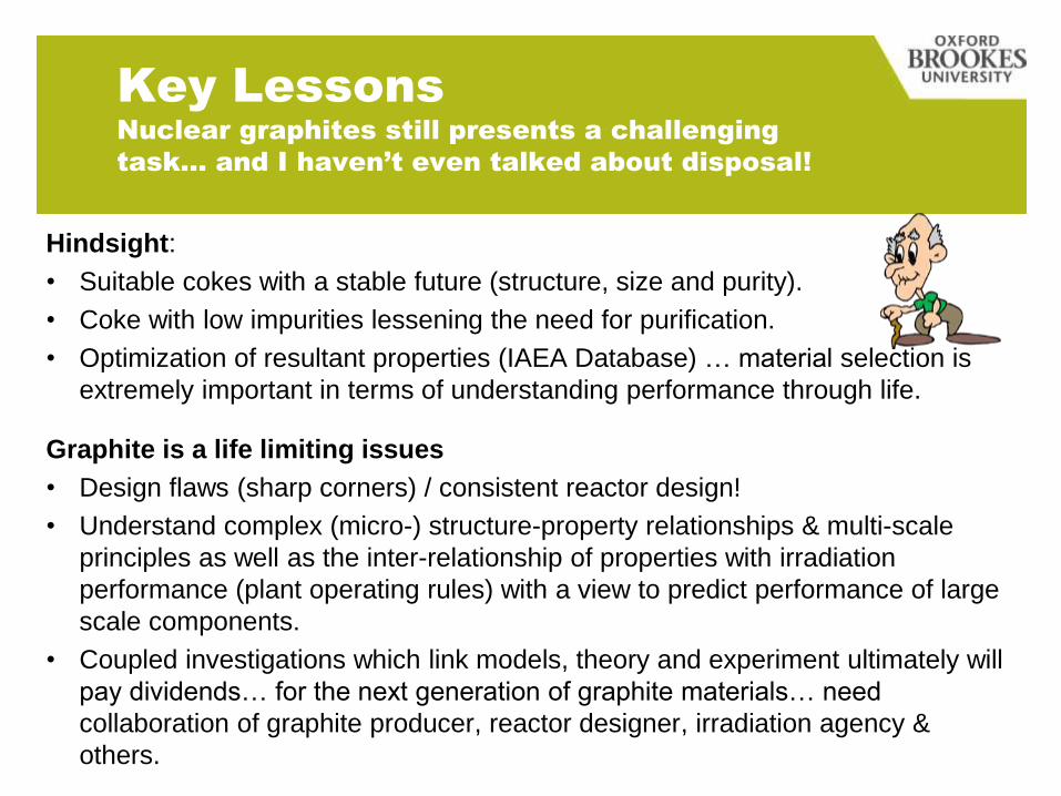
Key Lessons
Nuclear graphites still presents a challenging
task… and I haven’t even talked about disposal!
Hindsight:
• Suitable cokes with a stable future (structure, size and purity).
• Coke with low impurities lessening the need for purification.
• Optimization of resultant properties (IAEA Database) … material selection is
extremely important in terms of understanding performance through life.
Graphite is a life limiting issues
• Design flaws (sharp corners) / consistent reactor design!
• Understand complex (micro-) structure-property relationships & multi-scale
principles as well as the inter-relationship of properties with irradiation
performance (plant operating rules) with a view to predict performance of large
scale components.
• Coupled investigations which link models, theory and experiment ultimately will
pay dividends… for the next generation of graphite materials… need
collaboration of graphite producer, reactor designer, irradiation agency &
others.
Disruptive Technology
Further Information!
For further information:
http://mems.brookes.ac.uk ;
http://www.journals.elsevier.com/carbon/
www.facebook.com/brookes.mems
@OBU_MEMS, @GNEIGHBOUR
Email – [email protected]
www

![Journal of Nuclear Materials - INL Advanced Reactor ... Situ...the properties of nuclear graphite [5–10]. Under irradiation, polycrystalline graphite undergoes complex dimensional](https://img.pdfslide.net/doc/110x75/60f85869ae21df3ef94aa65a/journal-of-nuclear-materials-inl-advanced-reactor-situ-the-properties-of.jpg)