Embed Size (px)
Citation preview
NEI 99-01 [Revision 6]
Development of Emergency Action Levels for Non-Passive Reactors
November 2012

[THIS PAGE IS LEFT BLANK INTENTIONALLY]

Nuclear Energy Institute, 1776 I Street N. W., Suite 400, Washington D.C. (202.739.8000)
NEI 99-01 [Revision 6]
Nuclear Energy Institute
Development of Emergency Action Levels for Non-Passive Reactors
November 2012

ACKNOWLEDGMENTS
This document was prepared by the Nuclear Energy Institute (NEI) Emergency Action Level (EAL) Task Force. NEI Chairperson: David Young Preparation Team
Larry Baker – Exelon Nuclear/Corporate Craig Banner – PSEG Nuclear/Salem and Hope Creek Nuclear Generating Stations/USA John Egdorf – Dominion Generation/Kewaunee Power Station Jack Lewis – Entergy Nuclear/Corporate C. Kelly Walker – Operations Support Services, Inc.
Review Team
Chris Boone – Southern Nuclear/Corporate John Callahan – Xcel Energy/Corporate/USA Bill Chausse – Enercon Services, Inc. Kent Crocker – Progress Energy/Brunswick Nuclear Plant Don Crowl – Duke Energy/Corporate Roger Freeman – Constellation Energy Nuclear Group/Corporate Walt Lee – TVA Nuclear/Corporate Ken Meade – FENOC/Corporate Don Mothena – NextEra Energy/Corporate David Stobaugh – EP Consulting, LLC Nick Turner – Callaway Plant/STARS Maureen Zawalick – Diablo Canyon Power Plant/STARS
NOTICE
Neither NEI, nor any of its employees, members, supporting organizations, contractors, or consultants make any warranty, expressed or implied, or assume any legal responsibility for the accuracy or completeness of, or assume any liability for damages resulting from any use of, any information apparatus, methods, or process disclosed in this report or that such may not infringe privately owned rights.

NEI 99-01 (Revision 6) November 2012
i
EXECUTIVE SUMMARY
Federal regulations require that a nuclear power plant operator develop a scheme for the classification of emergency events and conditions. This scheme is a fundamental component of an emergency plan in that it provides the defined thresholds that will allow site personnel to rapidly implement a range of pre-planned emergency response measures. An emergency classification scheme also facilitates timely decision-making by an Offsite Response Organization (ORO) concerning the implementation of precautionary or protective actions for the public.
The purpose of Nuclear Energy Institute (NEI) 99-01 is to provide guidance to nuclear power plant operators for the development of a site-specific emergency classification scheme. The methodology described in this document is consistent with Federal regulations, and related US Nuclear Regulatory Commission (NRC) requirements and guidance. In particular, this methodology has been endorsed by the NRC as an acceptable approach to meeting the requirements of 10 CFR § 50.47(b)(4), related sections of 10 CFR § 50, Appendix E, and the associated planning standard evaluation elements of NUREG-0654/ FEMA-REP-1, Rev. 1, Criteria for Preparation and Evaluation of Radiological Emergency Response Plans and Preparedness in Support of Nuclear Power Plants, November 1980.
NEI 99-01 contains a set of generic Initiating Conditions (ICs), Emergency Action Levels (EALs) and fission product barrier status thresholds. It also includes supporting technical basis information, developer notes and recommended classification instructions for users. Users should implement ICs, EALs and thresholds that are as close as possible to the generic material presented in this document with allowance for changes necessary to address site-specific considerations such as plant design, location, terminology, etc.
Properly implemented, the guidance in NEI 99-01 will yield a site-specific emergency classification scheme with clearly defined and readily observable EALs and thresholds. Other benefits include the development of a sound basis document, the adoption of industry-standard instructions for emergency classification (e.g., transient events, classification of multiple events, upgrading, downgrading, etc.), and incorporation of features to improve human performance. An emergency classification using this scheme will be appropriate to the risk posed to plant workers and the public, and should be the same as that made by another NEI 99-01 user plant in response to a similar event.
The individuals responsible for developing an emergency classification scheme are strongly encouraged to review all applicable NRC requirements and guidance prior to beginning their efforts. Questions concerning this document may be directed to the NEI Emergency Preparedness staff, NEI EAL task force members or submitted to the Emergency Preparedness Frequently Asked Questions process.
Finally, unique State and local requirements associated with an emergency classification scheme are not reflected in this guidance. Incorporation of these requirements may be performed on a case-by-case basis in conjunction with the appropriate ORO agency. Any such changes will require a review under the applicable sections of 10 CFR 50.

NEI 99-01 (Revision 6) November 2012
ii
[THIS PAGE IS LEFT BLANK INTENTIONALLY]

NEI 99-01 (Revision 6) November 2012
iii
TABLE OF CONTENTS
EXECUTIVE SUMMARY ........................................................................................................ i
1 REGULATORY BACKGROUND ..................................................................................... 1
1.1 OPERATING REACTORS ..................................................................................................1
1.2 PERMANENTLY DEFUELED STATION .............................................................................1
1.3 INDEPENDENT SPENT FUEL STORAGE INSTALLATION (ISFSI).....................................2
1.4 NRC ORDER EA-12-051 ................................................................................................2
1.5 APPLICABILITY TO ADVANCED AND SMALL MODULAR REACTOR DESIGNS ...............4
2 KEY TERMINOLOGY USED IN NEI 99-01 .................................................................... 5
2.1 EMERGENCY CLASSIFICATION LEVEL (ECL) ...............................................................5
2.2 INITIATING CONDITION (IC) ..........................................................................................7
2.3 EMERGENCY ACTION LEVEL (EAL) .............................................................................7
2.4 FISSION PRODUCT BARRIER THRESHOLD .....................................................................7
3 DESIGN OF THE NEI 99-01 EMERGENCY CLASSIFICATION SCHEME ....................... 9
3.1 ASSIGNMENT OF EMERGENCY CLASSIFICATION LEVELS (ECLS) ...............................9
3.2 TYPES OF INITIATING CONDITIONS AND EMERGENCY ACTION LEVELS....................12
3.3 NSSS DESIGN DIFFERENCES ........................................................................................12
3.4 ORGANIZATION AND PRESENTATION OF GENERIC INFORMATION .............................13
3.5 IC AND EAL MODE APPLICABILITY ............................................................................14
4 SITE-SPECIFIC SCHEME DEVELOPMENT GUIDANCE .............................................. 16
4.1 GENERAL IMPLEMENTATION GUIDANCE ....................................................................16
4.2 CRITICAL CHARACTERISTICS ......................................................................................17
4.3 INSTRUMENTATION USED FOR EALS ..........................................................................18
4.4 PRESENTATION OF SCHEME INFORMATION TO USERS ...............................................18
4.5 INTEGRATION OF ICS/EALS WITH PLANT PROCEDURES ...........................................19
4.6 BASIS DOCUMENT .........................................................................................................20
4.7 DEVELOPER AND USER FEEDBACK ..............................................................................21
5 GUIDANCE ON MAKING EMERGENCY CLASSIFICATIONS ...................................... 22
5.1 GENERAL CONSIDERATIONS ........................................................................................22
5.2 CLASSIFICATION METHODOLOGY ...............................................................................23
5.3 CLASSIFICATION OF MULTIPLE EVENTS AND CONDITIONS ........................................23
5.4 CONSIDERATION OF MODE CHANGES DURING CLASSIFICATION ..............................23

NEI 99-01 (Revision 6) November 2012
iv
5.5 CLASSIFICATION OF IMMINENT CONDITIONS .............................................................24
5.6 EMERGENCY CLASSIFICATION LEVEL UPGRADING AND DOWNGRADING .................24
5.7 CLASSIFICATION OF SHORT-LIVED EVENTS ...............................................................25
5.8 CLASSIFICATION OF TRANSIENT CONDITIONS ............................................................25
5.9 AFTER-THE-FACT DISCOVERY OF AN EMERGENCY EVENT OR CONDITION ..............26
5.10 RETRACTION OF AN EMERGENCY DECLARATION .......................................................26
6 ABNORMAL RAD LEVELS / RADIOLOGICAL EFFLUENT ICS/EALS ........................ 27
7 COLD SHUTDOWN / REFUELING SYSTEM MALFUNCTION ICS/EALS .................... 49
8 INDEPENDENT SPENT FUEL STORAGE INSTALLATION (ISFSI) ICS/EALS .............. 76
9 FISSION PRODUCT BARRIER ICS/EALS .................................................................. 78
10 HAZARDS AND OTHER CONDITIONS AFFECTING PLANT SAFETY ICS/EALS ....... 123
11 SYSTEM MALFUNCTION ICS/EALS ......................................................................... 148
APPENDIX A – ACRONYMS AND ABBREVIATIONS ........................................................ A-1
APPENDIX B – DEFINITIONS ........................................................................................... B-1
APPENDIX C – PERMANENTLY DEFUELED STATION ICs/EALs .................................... C-1
NEI 99-01 (Revision 6) November 2012
1
DEVELOMENT OF EMERGENCY ACTION LEVELS FOR NON-PASSIVE REACTORS
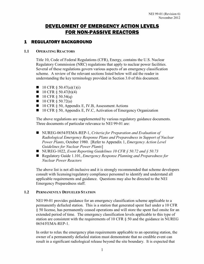
1 REGULATORY BACKGROUND
1.1 OPERATING REACTORS
Title 10, Code of Federal Regulations (CFR), Energy, contains the U.S. Nuclear Regulatory Commission (NRC) regulations that apply to nuclear power facilities. Several of these regulations govern various aspects of an emergency classification scheme. A review of the relevant sections listed below will aid the reader in understanding the key terminology provided in Section 3.0 of this document. 10 CFR § 50.47(a)(1)(i) 10 CFR § 50.47(b)(4) 10 CFR § 50.54(q) 10 CFR § 50.72(a) 10 CFR § 50, Appendix E, IV.B, Assessment Actions 10 CFR § 50, Appendix E, IV.C, Activation of Emergency Organization
The above regulations are supplemented by various regulatory guidance documents. Three documents of particular relevance to NEI 99-01 are:
NUREG-0654/FEMA-REP-1, Criteria for Preparation and Evaluation of
Radiological Emergency Response Plans and Preparedness in Support of Nuclear Power Plants, October 1980. [Refer to Appendix 1, Emergency Action Level Guidelines for Nuclear Power Plants]
NUREG-1022, Event Reporting Guidelines 10 CFR § 50.72 and § 50.73 Regulatory Guide 1.101, Emergency Response Planning and Preparedness for
Nuclear Power Reactors
The above list is not all-inclusive and it is strongly recommended that scheme developers consult with licensing/regulatory compliance personnel to identify and understand all applicable requirements and guidance. Questions may also be directed to the NEI Emergency Preparedness staff.
1.2 PERMANENTLY DEFUELED STATION
NEI 99-01 provides guidance for an emergency classification scheme applicable to a permanently defueled station. This is a station that generated spent fuel under a 10 CFR § 50 license, has permanently ceased operations and will store the spent fuel onsite for an extended period of time. The emergency classification levels applicable to this type of station are consistent with the requirements of 10 CFR § 50 and the guidance in NUREG 0654/FEMA-REP-1.
In order to relax the emergency plan requirements applicable to an operating station, the owner of a permanently defueled station must demonstrate that no credible event can result in a significant radiological release beyond the site boundary. It is expected that

NEI 99-01 (Revision 6) November 2012
2
this verification will confirm that the source term and motive force available in the permanently defueled condition are insufficient to warrant classifications of a Site Area Emergency or General Emergency. Therefore, the generic Initiating Conditions (ICs) and Emergency Action Levels (EALs) applicable to a permanently defueled station may result in either a Notification of Unusual Event (NOUE) or an Alert classification.
The generic ICs and EALs are presented in Appendix C, Permanently Defueled Station ICs/EALs.
1.3 INDEPENDENT SPENT FUEL STORAGE INSTALLATION (ISFSI)
Selected guidance in NEI 99-01 is applicable to licensees electing to use their 10 CFR 50 emergency plan to fulfill the requirements of 10 CFR 72.32 for a stand-alone ISFSI. The emergency classification levels applicable to an ISFSI are consistent with the requirements of 10 CFR § 50 and the guidance in NUREG 0654/FEMA-REP-1. The initiating conditions germane to a 10 CFR § 72.32 emergency plan (as described in NUREG-1567) are subsumed within the classification scheme for a 10 CFR § 50.47 emergency plan.
The generic ICs and EALs for an ISFSI are presented in Section 8, ISFSI ICs/EALs. IC E-HU1 covers the spectrum of credible natural and man-made events included within the scope of an ISFSI design. This IC is not applicable to installations or facilities that may process and/or repackage spent fuel (e.g., a Monitored Retrievable Storage Facility or an ISFSI at a spent fuel processing facility). In addition, appropriate aspects of IC HU1 and IC HA1 should also be included to address a HOSTILE ACTION directed against an ISFSI.
The analysis of potential onsite and offsite consequences of accidental releases associated with the operation of an ISFSI is contained in NUREG-1140, A Regulatory Analysis on Emergency Preparedness for Fuel Cycle and Other Radioactive Material Licensees. NUREG-1140 concluded that the postulated worst-case accident involving an ISFSI has insignificant consequences to public health and safety. This evaluation shows that the maximum offsite dose to a member of the public due to an accidental release of radioactive materials would not exceed 1 rem Effective Dose Equivalent.
Regarding the above information, the expectations for an offsite response to an Alert classified under a 10 CFR § 72.32 emergency plan are generally consistent with those for a Notification of Unusual Event in a 10 CFR § 50.47 emergency plan (e.g., to provide assistance if requested). Also, the licensee’s Emergency Response Organization (ERO) required for 10 CFR § 72.32 emergency plan is different than that prescribed for a 10 CFR § 50.47 emergency plan (e.g., no emergency technical support function).
1.4 NRC ORDER EA-12-051
The Fukushima Daiichi accident of March 11, 2012, was the result of a tsunami that exceeded the plant’s design basis and flooded the site’s emergency electrical power supplies and distribution systems. This caused an extended loss of power that severely compromised the key safety functions of core cooling and containment integrity, and ultimately led to core damage in three reactors. While the loss of power also impaired the

NEI 99-01 (Revision 6) November 2012
3
spent fuel pool cooling function, sufficient water inventory was maintained in the pools to preclude fuel damage from the loss of cooling. Following a review of the Fukushima Daiichi accident, the NRC concluded that several measures were necessary to ensure adequate protection of public health and safety under the provisions of the backfit rule, 10 CFR 50.109(a)(4)(ii). Among them was to provide each spent fuel pool with reliable level instrumentation to significantly enhance the ability of key decision-makers to allocate resources effectively following a beyond design basis event. To this end, the NRC issued Order EA-12-051, Issuance of Order to Modify Licenses with Regard to Reliable Spent Fuel Pool Instrumentation, on March 12, 2012, to all US nuclear plants with an operating license, construction permit, or combined construction and operating license. NRC Order EA-12-051 states, in part, “All licensees … shall have a reliable indication of the water level in associated spent fuel storage pools capable of supporting identification of the following pool water level conditions by trained personnel: (1) level that is adequate to support operation of the normal fuel pool cooling system, (2) level that is adequate to provide substantial radiation shielding for a person standing on the spent fuel pool operating deck, and (3) level where fuel remains covered and actions to implement make-up water addition should no longer be deferred.” To this end, all licensees must provide: A primary and back-up level instrument that will monitor water level from the normal
level to the top of the used fuel rack in the pool; A display in an area accessible following a severe event; and Independent electrical power to each instrument channel and provide an alternate
remote power connection capability.
NEI 12-02, Industry Guidance for Compliance with NRC Order EA-12-051, “To Modify Licenses with Regard to Reliable Spent Fuel Pool Instrumentation”, provides guidance for complying with NRC Order EA-12-051. NEI 99-01, Revision 6, includes three EALs that reflect the availability of the enhanced spent fuel pool level instrumentation associated with NRC Order EA-12-051. These EALs are included within existing IC AA2, and new ICs AS2 and AG2. Associated EAL notes, bases and developer notes are also provided. It is recommended that these EALs be implemented when the enhanced spent fuel pool level instrumentation is available for use. The regulatory process that licensees follow to make changes to their emergency plan, including non-scheme changes to EALs, is 10 CFR 50.54(q). In accordance with this regulation, licensees are responsible for evaluating a proposed change and determining whether or not it results in a reduction in the effectiveness of the plan. As a result of the licensee's determination, the licensee will either make the change or submit it to the NRC for prior review and approval in accordance with 10 CFR 50.90.

NEI 99-01 (Revision 6) November 2012
4
1.5 APPLICABILITY TO ADVANCED AND SMALL MODULAR REACTOR DESIGNS
The guidance in this document primarily addresses commercial nuclear power reactors in the United States, operating or permanently defueled, as of 2012 (so called 1st and 2nd generation plant designs); however, it may be adapted to advanced non-passive designs (often referred to as 3rd generation plant designs) as well. Developers of an emergency classification scheme for an advanced non-passive reactor plant may need to propose deviations from the generic guidance to account for the differences in design parameters and criteria, and operating characteristics and capabilities, between 2nd and 3rd generation plants.
There are significant design and operating differences between large commercial nuclear power plants (of any generation) and Small Modular Reactors (SMRs) (e.g., differences in source term). For this reason, this document is not applicable to SMRs.

NEI 99-01 (Revision 6) November 2012
5
2 KEY TERMINOLOGY USED IN NEI 99-01
There are several key terms that appear throughout the NEI 99-01 methodology. These terms are introduced in this section to support understanding of subsequent material. As an aid to the reader, the following table is provided as an overview to illustrate the relationship of the terms to each other.
Emergency Classification Level Unusual Event Alert SAE GE
Initiating Condition Initiating Condition Initiating Condition Initiating Condition
Emergency Action Level (1) • Operating Mode
Applicability • Notes • Basis
Emergency Action Level (1) • Operating Mode
Applicability • Notes • Basis
Emergency Action Level (1) • Operating Mode
Applicability • Notes • Basis
Emergency Action Level (1) • Operating Mode
Applicability • Notes • Basis
(1) - When making an emergency classification, the Emergency Director must consider all information having a bearing on the proper assessment of an Initiating Condition. This includes the Emergency Action Level (EAL) plus the associated Operating Mode Applicability, Notes and the informing Basis information. In the Recognition Category F matrices, EALs are referred to as Fission Product Barrier Thresholds; the thresholds serve the same function as an EAL.
2.1 EMERGENCY CLASSIFICATION LEVEL (ECL)
One of a set of names or titles established by the US Nuclear Regulatory Commission (NRC) for grouping off-normal events or conditions according to (1) potential or actual effects or consequences, and (2) resulting onsite and offsite response actions. The emergency classification levels, in ascending order of severity, are: Notification of Unusual Event (NOUE) Alert Site Area Emergency (SAE) General Emergency (GE)
2.1.1 Notification of Unusual Event (NOUE)1
Events are in progress or have occurred which indicate a potential degradation of the level of safety of the plant or indicate a security threat to facility protection has been initiated. No releases of radioactive material requiring offsite response or monitoring are expected unless further degradation of safety systems occurs.
1 This term is sometimes shortened to Unusual Event (UE) or other similar site-specific terminology. The terms Notification of Unusual Event, NOUE and Unusual Event are used interchangeably throughout this document
NEI 99-01 (Revision 6) November 2012
6
Purpose: The purpose of this classification is to assure that the first step in future response has been carried out, to bring the operations staff to a state of readiness, and to provide systematic handling of unusual event information and decision-making.
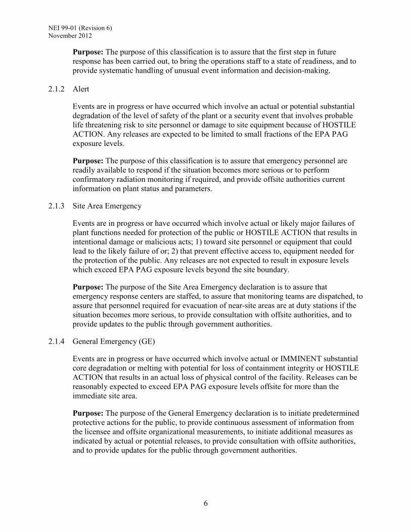
2.1.2 Alert
Events are in progress or have occurred which involve an actual or potential substantial degradation of the level of safety of the plant or a security event that involves probable life threatening risk to site personnel or damage to site equipment because of HOSTILE ACTION. Any releases are expected to be limited to small fractions of the EPA PAG exposure levels.
Purpose: The purpose of this classification is to assure that emergency personnel are readily available to respond if the situation becomes more serious or to perform confirmatory radiation monitoring if required, and provide offsite authorities current information on plant status and parameters.
2.1.3 Site Area Emergency
Events are in progress or have occurred which involve actual or likely major failures of plant functions needed for protection of the public or HOSTILE ACTION that results in intentional damage or malicious acts; 1) toward site personnel or equipment that could lead to the likely failure of or; 2) that prevent effective access to, equipment needed for the protection of the public. Any releases are not expected to result in exposure levels which exceed EPA PAG exposure levels beyond the site boundary.
Purpose: The purpose of the Site Area Emergency declaration is to assure that emergency response centers are staffed, to assure that monitoring teams are dispatched, to assure that personnel required for evacuation of near-site areas are at duty stations if the situation becomes more serious, to provide consultation with offsite authorities, and to provide updates to the public through government authorities.
2.1.4 General Emergency (GE)
Events are in progress or have occurred which involve actual or IMMINENT substantial core degradation or melting with potential for loss of containment integrity or HOSTILE ACTION that results in an actual loss of physical control of the facility. Releases can be reasonably expected to exceed EPA PAG exposure levels offsite for more than the immediate site area.
Purpose: The purpose of the General Emergency declaration is to initiate predetermined protective actions for the public, to provide continuous assessment of information from the licensee and offsite organizational measurements, to initiate additional measures as indicated by actual or potential releases, to provide consultation with offsite authorities, and to provide updates for the public through government authorities.

NEI 99-01 (Revision 6) November 2012
7
2.2 INITIATING CONDITION (IC)
An event or condition that aligns with the definition of one of the four emergency classification levels by virtue of the potential or actual effects or consequences.
Discussion: An IC describes an event or condition, the severity or consequences of which meets the definition of an emergency classification level. An IC can be expressed as a continuous, measurable parameter (e.g., RCS leakage), an event (e.g., an earthquake) or the status of one or more fission product barriers (e.g., loss of the RCS barrier).
Appendix 1 of NUREG-0654 does not contain example Emergency Action Levels (EALs) for each ECL, but rather Initiating Conditions (i.e., plant conditions that indicate that a radiological emergency, or events that could lead to a radiological emergency, has occurred). NUREG-0654 states that the Initiating Conditions form the basis for establishment by a licensee of the specific plant instrumentation readings (as applicable) which, if exceeded, would initiate the emergency classification. Thus, it is the specific instrument readings that would be the EALs.
Considerations for the assignment of a particular Initiating Condition to an emergency classification level are discussed in Section 3.
2.3 EMERGENCY ACTION LEVEL (EAL)
A pre-determined, site-specific, observable threshold for an Initiating Condition that, when met or exceeded, places the plant in a given emergency classification level.
Discussion: EAL statements may utilize a variety of criteria including instrument readings and status indications; observable events; results of calculations and analyses; entry into particular procedures; and the occurrence of natural phenomena.
2.4 FISSION PRODUCT BARRIER THRESHOLD
A pre-determined, site-specific, observable threshold indicating the loss or potential loss of a fission product barrier.
Discussion: Fission product barrier thresholds represent threats to the defense in depth design concept that precludes the release of radioactive fission products to the environment. This concept relies on multiple physical barriers, any one of which, if maintained intact, precludes the release of significant amounts of radioactive fission products to the environment. The primary fission product barriers are:
Fuel Clad Reactor Coolant System (RCS) Containment Upon determination that one or more fission product barrier thresholds have been exceeded, the combination of barrier loss and/or potential loss thresholds is compared to the fission product barrier IC/EAL criteria to determine the appropriate ECL.
In some accident sequences, the ICs and EALs presented in the Abnormal Radiation

NEI 99-01 (Revision 6) November 2012
8
Levels/ Radiological Effluent (A) Recognition Category will be exceeded at the same time, or shortly after, the loss of one or more fission product barriers. This redundancy is intentional as the former ICs address radioactivity releases that result in certain offsite doses from whatever cause, including events that might not be fully encompassed by fission product barriers (e.g., spent fuel pool accidents, design containment leakage following a LOCA, etc.).

NEI 99-01 (Revision 6) November 2012
9
3 DESIGN OF THE NEI 99-01 EMERGENCY CLASSIFICATION SCHEME
3.1 ASSIGNMENT OF EMERGENCY CLASSIFICATION LEVELS (ECLS)
An effective emergency classification scheme must incorporate a realistic and accurate assessment of risk, both to plant workers and the public. There are obvious health and safety risks in underestimating the potential or actual threat from an event or condition; however, there are also risks in overestimating the threat as well (e.g., harm that may occur during an evacuation). The NEI 99-01 emergency classification scheme attempts to strike an appropriate balance between reasonably anticipated event or condition consequences, potential accident trajectories, and risk avoidance or minimization.
There are a range of “non-emergency events” reported to the US Nuclear Regulatory Commission (NRC) staff in accordance with the requirements of 10 CFR § 50.72. Guidance concerning these reporting requirements, and example events, are provided in NUREG-1022. Certain events reportable under the provisions of 10 CFR § 50.72 may also require the declaration of an emergency.
In order to align each Initiating Conditions (IC) with the appropriate ECL, it was necessary to determine the attributes of each ECL. The goal of this process is to answer the question, “What events or conditions should be placed under each ECL?” The following sources provided information and context for the development of ECL attributes.
Assessments of the effects and consequences of different types of events and conditions
Typical abnormal and emergency operating procedure setpoints and transition criteria Typical Technical Specification limits and controls Radiological Effluent Technical Specifications (RETS)/Offsite Dose Calculation
Manual (ODCM) radiological release limits Review of selected Updated Final Safety Analysis Report (UFSAR) accident analyses Environmental Protection Agency (EPA) Protective Action Guidelines (PAGs) NUREG 0654, Appendix 1, Emergency Action Level Guidelines for Nuclear Power
Plants Industry Operating Experience Input from industry subject matter experts and NRC staff members
The following ECL attributes were created by the Revision 6 Preparation Team to aid in the development of ICs and Emergency Action Levels (EALs). The team decided to include the attributes in this revision since they may be useful in briefing and training settings (e.g., helping an Emergency Director understand why a particular condition is classified as an Alert). It should be stressed that developers not attempt to redefine these attributes or apply them in any fashion that would change the generic guidance contained in this document2.
2 The use of ECL attributes is at the discretion of a licensee and is not a requirement of the NRC. If a licensee chooses in incorporate the ECL attributes into their scheme basis document, it must be very clear that the NRC staff has not endorsed their acceptability or application for any purpose. In particular, the staff does not consider the attribute statements to supersede the established ECL definitions. As a result, the use of the attributes as a basis for justifying EAL changes is unacceptable.
NEI 99-01 (Revision 6) November 2012
10
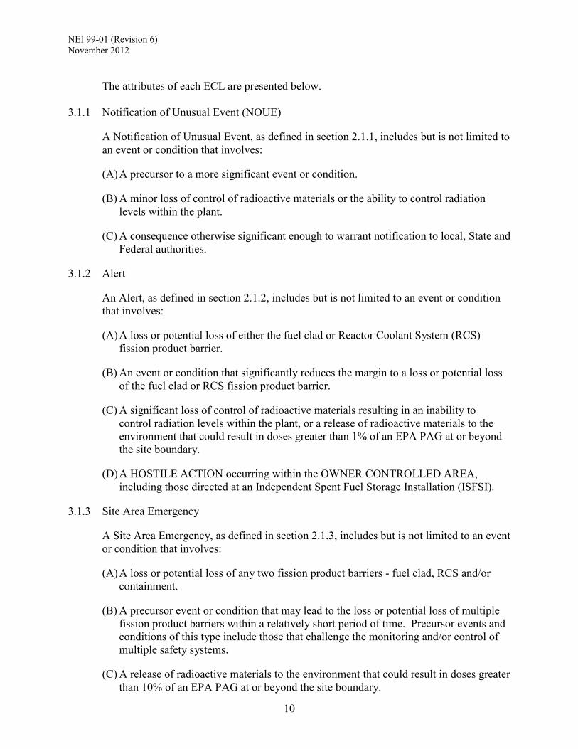
The attributes of each ECL are presented below.
3.1.1 Notification of Unusual Event (NOUE)
A Notification of Unusual Event, as defined in section 2.1.1, includes but is not limited to an event or condition that involves:
(A) A precursor to a more significant event or condition.
(B) A minor loss of control of radioactive materials or the ability to control radiation levels within the plant.
(C) A consequence otherwise significant enough to warrant notification to local, State and Federal authorities.
3.1.2 Alert
An Alert, as defined in section 2.1.2, includes but is not limited to an event or condition that involves:
(A) A loss or potential loss of either the fuel clad or Reactor Coolant System (RCS) fission product barrier.
(B) An event or condition that significantly reduces the margin to a loss or potential loss of the fuel clad or RCS fission product barrier.
(C) A significant loss of control of radioactive materials resulting in an inability to control radiation levels within the plant, or a release of radioactive materials to the environment that could result in doses greater than 1% of an EPA PAG at or beyond the site boundary.
(D) A HOSTILE ACTION occurring within the OWNER CONTROLLED AREA, including those directed at an Independent Spent Fuel Storage Installation (ISFSI).
3.1.3 Site Area Emergency
A Site Area Emergency, as defined in section 2.1.3, includes but is not limited to an event or condition that involves:
(A) A loss or potential loss of any two fission product barriers - fuel clad, RCS and/or containment.
(B) A precursor event or condition that may lead to the loss or potential loss of multiple fission product barriers within a relatively short period of time. Precursor events and conditions of this type include those that challenge the monitoring and/or control of multiple safety systems.
(C) A release of radioactive materials to the environment that could result in doses greater than 10% of an EPA PAG at or beyond the site boundary.

NEI 99-01 (Revision 6) November 2012
11
(D) A HOSTILE ACTION occurring within the plant PROTECTED AREA.
3.1.4 General Emergency
A General Emergency, as defined in section 2.1.4, includes but is not limited to an event or condition that involves:
(A) Loss of any two fission product barriers AND loss or potential loss of the third barrier - fuel clad, RCS and/or containment.
(B) A precursor event or condition that, unmitigated, may lead to a loss of all three fission product barriers. Precursor events and conditions of this type include those that lead directly to core damage and loss of containment integrity.
(C) A release of radioactive materials to the environment that could result in doses greater than an EPA PAG at or beyond the site boundary.
(D) A HOSTILE ACTION resulting in the loss of key safety functions (reactivity control, core cooling/RPV water level or RCS heat removal) or damage to spent fuel.
3.1.5 Risk-Informed Insights
Emergency preparedness is a defense-in-depth measure that is independent of the assessed risk from any particular accident sequence; however, the development of an effective emergency classification scheme can benefit from a review of risk-based assessment results. To that end, the development and assignment of certain ICs and EALs also considered insights from several site-specific probabilistic safety assessments (PSA - also known as probabilistic risk assessment, PRA). Some generic insights from this review included:
1. Accident sequences involving a prolonged loss of all AC power are significant contributors to core damage frequency at many Pressurized Water Reactors (PWRs) and Boiling Water Reactors (BWRs). For this reason, a loss of all AC power for greater than 15 minutes, with the plant at or above Hot Shutdown, was assigned an ECL of Site Area Emergency. Precursor events to a loss of all AC power were also included as an Unusual Event and an Alert.
A station blackout coping analyses performed in response to 10 CFR § 50.63 and Regulatory Guide 1.155, Station Blackout, may be used to determine a time-based criterion to demarcate between a Site Area Emergency and a General Emergency. The time dimension is critical to a properly anticipatory emergency declaration since the goal is to maximize the time available for State and local officials to develop and implement offsite protective actions.
2. For severe core damage events, uncertainties exist in phenomena important to accident progressions leading to containment failure. Because of these uncertainties, predicting the status of containment integrity may be difficult under severe accident conditions. This is why maintaining containment integrity alone following sequences leading to severe core damage is an insufficient basis for not escalating to a General Emergency.

NEI 99-01 (Revision 6) November 2012
12
3. PSAs indicated that leading contributors to latent fatalities were sequences involving a containment bypass, a large Loss of Coolant Accident (LOCA) with early containment failure, a Station Blackout lasting longer than the site-specific coping period, and a reactor coolant pump seal failure. The generic EAL methodology needs to be sufficiently rigorous to address these sequences in a timely fashion.
3.2 TYPES OF INITIATING CONDITIONS AND EMERGENCY ACTION LEVELS
The NEI 99-01 methodology makes use of symptom-based, barrier-based and event-based ICs and EALs. Each type is discussed below.
Symptom-based ICs and EALs are parameters or conditions that are measurable over some range using plant instrumentation (e.g., core temperature, reactor coolant level, radiological effluent, etc.). When one or more of these parameters or conditions are off-normal, reactor operators will implement procedures to identify the probable cause(s) and take corrective action.
Fission product barrier-based ICs and EALs are the subset of symptom-based EALs that refer specifically to the level of challenge to the principal barriers against the release of radioactive material from the reactor core to the environment. These barriers are the fuel cladding, the reactor coolant system pressure boundary, and the containment. The barrier-based ICs and EALs consider the level of challenge to each individual barrier - potentially lost and lost - and the total number of barriers under challenge.
Event-based ICs and EALs define a variety of specific occurrences that have potential or actual safety significance. These include the failure of an automatic reactor scram/trip to shut down the reactor, natural phenomena (e.g., an earthquake), or man-made hazards such as a toxic gas release.
3.3 NSSS DESIGN DIFFERENCES
The NEI 99-01 emergency classification scheme accounts for the design differences between PWRs and BWRs by specifying EALs unique to each type of Nuclear Steam Supply System (NSSS). There are also significant design differences among PWR NSSSs; therefore, guidance is provided to aid in the development of EALs appropriate to different PWR NSSS types. Where necessary, development guidance also addresses unique considerations for advanced non-passive reactor designs such as the Advanced Boiling Water Reactor (ABWR), the Advanced Pressurized Water Reactor (APWR) and the Evolutionary Power Reactor (EPR).
Developers will need to consider the relevant aspects of their plant’s design and operating characteristics when converting the generic guidance of this document into a site-specific classification scheme. The goal is to maintain as much fidelity as possible to the intent of generic ICs and EALs within the constraints imposed by the plant design and operating characteristics. To this end, developers of a scheme for an advanced non-passive reactor may need to add, modify or delete some information contained in this document; these changes will be reviewed for acceptability by the NRC as part of the scheme approval process.

NEI 99-01 (Revision 6) November 2012
13
The guidance in NEI 99-01 is not applicable to advanced passive light water reactor designs. An Emergency Classification Scheme for this type of plant should be developed in accordance with NEI 07-01, Methodology for Development of Emergency Action Levels, Advanced Passive Light Water Reactors.
3.4 ORGANIZATION AND PRESENTATION OF GENERIC INFORMATION
The scheme’s generic information is organized by Recognition Category in the following order.
A - Abnormal Radiation Levels / Radiological Effluent – Section 6 C - Cold Shutdown / Refueling System Malfunction – Section 7 E - Independent Spent Fuel Storage Installation (ISFSI) – Section 8 F - Fission Product Barrier – Section 9 H - Hazards and Other Conditions Affecting Plant Safety – Section 10 S - System Malfunction – Section 11 PD - Permanently Defueled Station – Appendix C Each Recognition Category section contains a matrix showing the ICs and their associated emergency classification levels. The following information and guidance is provided for each IC:
ECL – the assigned emergency classification level for the IC.
Initiating Condition – provides a summary description of the emergency event or condition.
Operating Mode Applicability – Lists the modes during which the IC and associated EAL(s) are applicable (i.e., are to be used to classify events or conditions).
Example Emergency Action Level(s) – Provides examples of reports and indications that are considered to meet the intent of the IC. Developers should address each example EAL. If the generic approach to the development of an example EAL cannot be used (e.g., an assumed instrumentation range is not available at the plant), the developer should attempt to specify an alternate means for identifying entry into the IC. For Recognition Category F, the fission product barrier thresholds are presented in tables applicable to BWRs and PWRs, and arranged by fission product barrier and the degree of barrier challenge (i.e., potential loss or loss). This presentation method shows the synergism among the thresholds, and supports accurate assessments.
Basis – Provides background information that explains the intent and application of the IC and EALs. In some cases, the basis also includes relevant source information and references.
Developer Notes - Information that supports the development of the site-specific ICs and EALs. This may include clarifications, references, examples, instructions for calculations, etc. Developer notes should not be included in the site’s emergency

NEI 99-01 (Revision 6) November 2012
14
classification scheme basis document. Developers may elect to include information resulting from a developer note action in a basis section.
ECL Assignment Attributes – Located within the Developer Notes section,
specifies the attribute used for assigning the IC to a given ECL.
3.5 IC AND EAL MODE APPLICABILITY
The NEI 99-01 emergency classification scheme was developed recognizing that the applicability of ICs and EALs will vary with plant mode. For example, some symptom-based ICs and EALs can be assessed only during the power operations, startup, or hot standby/shutdown modes of operation when all fission product barriers are in place, and plant instrumentation and safety systems are fully operational. In the cold shutdown and refueling modes, different symptom-based ICs and EALs will come into play to reflect the opening of systems for routine maintenance, the unavailability of some safety system components and the use of alternate instrumentation.
The following table shows which Recognition Categories are applicable in each plant mode. The ICs and EALs for a given Recognition Category are applicable in the indicated modes.
MODE APPLICABILITY MATRIX
Recognition Category Mode A C E F H PD S
Power Operations X X X X X Startup X X X X X
Hot Standby X X X X X Hot Shutdown X X X X X Cold Shutdown X X X X
Refueling X X X X Defueled X X X X
Permanently Defueled X X

NEI 99-01 (Revision 6) November 2012
15
Typical BWR Operating Modes
Power Operations (1): Mode Switch in Run
Startup (2): Mode Switch in Startup/Hot Standby or Refuel (with all vessel head bolts fully tensioned)
Hot Shutdown (3): Mode Switch in Shutdown, Average Reactor Coolant Temperature >200 °F
Cold Shutdown (4): Mode Switch in Shutdown, Average Reactor Coolant Temperature ≤ 200 °F
Refueling (5): Mode Switch in Shutdown or Refuel, and one or more vessel head bolts less than fully tensioned.
Typical PWR Operating Modes
Power Operations (1): Reactor Power > 5%, Keff ≥ 0.99
Startup (2): Reactor Power ≤ 5%, Keff ≥ 0.99
Hot Standby (3): RCS ≥ 350 °F, Keff < 0.99
Hot Shutdown (4): 200 °F < RCS < 350 °F, Keff < 0.99
Cold Shutdown (5): RCS < 200 °F, Keff < 0.99
Refueling (6): One or more vessel head closure bolts less than fully tensioned
Developers will need to incorporate the mode criteria from unit-specific Technical Specifications into their emergency classification scheme. In addition, the scheme must also include the following mode designation specific to NEI 99-01:
Defueled (None): All fuel removed from the reactor vessel (i.e., full core offload during refueling or extended outage).

NEI 99-01 (Revision 6) November 2012
16
4 SITE-SPECIFIC SCHEME DEVELOPMENT GUIDANCE
This section provides detailed guidance for developing a site-specific emergency classification scheme. Conceptually, the approach discussed here mirrors the approach used to prepare emergency operating procedures – generic material prepared by reactor vendor owners groups is converted by each nuclear power plant into site-specific emergency operating procedures. Likewise, the emergency classification scheme developer will use the generic guidance in NEI 99-01 to prepare a site-specific emergency classification scheme and the associated basis document.
It is important that the NEI 99-01 emergency classification scheme be implemented as an integrated package. Selected use of portions of this guidance is strongly discouraged as it will lead to an inconsistent or incomplete emergency classification scheme that will likely not receive the necessary regulatory approval.
4.1 GENERAL IMPLEMENTATION GUIDANCE
The guidance in NEI 99-01 is not intended to be applied to plants “as-is”; however, developers should attempt to keep their site-specific schemes as close to the generic guidance as possible. The goal is to meet the intent of the generic Initiating Conditions (ICs) and Emergency Action Levels (EALs) within the context of site-specific characteristics – locale, plant design, operating features, terminology, etc. Meeting this goal will result in a shorter and less cumbersome NRC review and approval process, closer alignment with the schemes of other nuclear power plant sites and better positioning to adopt future industry-wide scheme enhancements.
When properly developed, the ICs and EALs should be unambiguous and readily assessable.
As discussed in Section 3, the generic guidance includes ICs and example EALs. It is the intent of this guidance that both be included in site-specific documents as each serves a specific purpose. The IC is the fundamental event or condition requiring a declaration. The EAL(s) is the pre-determined threshold that defines when the IC is met. If some feature of the plant location or design is not compatible with a generic IC or EAL, efforts should be made to identify an alternate IC or EAL.
If an IC or EAL includes an explicit reference to a mode dependent technical specification limit that is not applicable to the plant, then that IC and/or EAL need not be included in the site-specific scheme. In these cases, developers must provide adequate documentation to justify why the IC and/or EAL were not incorporated (i.e., sufficient detail to allow a third party to understand the decision not to incorporate the generic guidance).
Useful acronyms and abbreviations associated with the NEI 99-01 emergency classification scheme are presented in Appendix A, Acronyms and Abbreviations. Site-specific entries may be added if necessary.
Many words or terms used in the NEI 99-01 emergency classification scheme have
NEI 99-01 (Revision 6) November 2012
17
scheme-specific definitions. These words and terms are identified by being set in all capital letters (i.e., ALL CAPS). The definitions are presented in Appendix B, Definitions.
Below are examples of acceptable modifications to the generic guidance. These may be incorporated depending upon site developer and user preferences.
The ICs within a Recognition Category may be placed in reverse order for presentation purposes (e.g., start with a General Emergency at the left/top of a user aid, followed by Site Area Emergency, Alert and NOUE).
The Initiating Condition numbering may be changed. The first letter of a Recognition Category designation may be changed, as follows,
provided the change is carried through for all of the associated IC identifiers. • R may be used in lieu of A • M may be used in lieu of S
For example, the Abnormal Radiation Levels / Radiological Effluent category designator “A” (for Abnormal) may be changed to “R” (for Radiation). This means that the associated ICs would be changed to RU1, RU2, RA1, etc.
The ICs and EALs from Recognition Categories S and C may be incorporated into a
common presentation method (e.g., one table) provided that all related notes and mode applicability requirements are maintained.
The ICs and EALs for Emergency Director judgment and security-related events may be placed under separate Recognition Categories.
The terms EAL and threshold may be used interchangeably.
The material in the Developer Notes section is included to assist developers with crafting correct IC and EAL statements. This material is not required to be in the final emergency classification scheme basis document.
4.2 CRITICAL CHARACTERISTICS
As discussed above, developers are encouraged to keep their site-specific schemes as close to the generic guidance as possible. When crafting the scheme, developers should satisfy themselves that certain critical characteristics have been met. These critical characteristics are listed below.
The ICs, EALs, Operating Mode Applicability criteria, Notes and Basis information are consistent with industry guidance; while the actual wording may be different, the classification intent is maintained. With respect to Recognition Category F, a site-specific scheme must include some type of user-aid to facilitate timely and accurate classification of fission product barrier losses and/or potential losses. The user-aid logic must be consistent with the classification logic presented in Section 9.
The ICs, EALs, Operating Mode Applicability criteria, Notes and Basis information are technically complete and accurate (i.e., they contain the information necessary to make a correct classification).
EAL statements use objective criteria and observable values.

NEI 99-01 (Revision 6) November 2012
18
ICs, EALs, Operating Mode Applicability and Note statements and formatting consider human factors and are user-friendly.
The scheme facilitates upgrading and downgrading of the emergency classification where necessary.
The scheme facilitates classification of multiple concurrent events or conditions.
4.3 INSTRUMENTATION USED FOR EALS
Instrumentation referenced in EAL statements should include that described in the emergency plan section which addresses 10 CFR 50.47(b)(8) and (9) and/or Chapter 7 of the FSAR. Instrumentation used for EALs need not be safety-related, addressed by a Technical Specification or ODCM/RETS control requirement, nor powered from an emergency power source; however, EAL developers should strive to incorporate instrumentation that is reliable and routinely maintained in accordance with site programs and procedures. Alarms referenced in EAL statements should be those that are the most operationally significant for the described event or condition.
Scheme developers should ensure that specified values used as EAL setpoints are within the calibrated range of the referenced instrumentation, and consider any automatic instrumentation functions that may impact accurate EAL assessment. In addition, EAL setpoint values should not use terms such as “off-scale low” or “off-scale high” since that type of reading may not be readily differentiated from an instrument failure. Findings and violations related to EAL instrumentation issues may be located on the NRC website.
4.4 PRESENTATION OF SCHEME INFORMATION TO USERS
The US Nuclear Regulatory Commission (NRC) expects licensees to establish and maintain the capability to assess, classify and declare an emergency condition promptly within 15 minutes after the availability of indications to plant operators that an emergency action level has been, or may be, exceeded. When writing an emergency classification procedure and creating related user aids, the developer must determine the presentation method(s) that best supports the end users by facilitating accurate and timely emergency classification. To this end, developers should consider the following points.
The first users of an emergency classification procedure are the operators in the Control Room. During the allowable classification time period, they may have responsibility to perform other critical tasks, and will likely have minimal assistance in making a classification assessment.
As an emergency situation evolves, members of the Control Room staff are likely to be the first personnel to notice a change in plant conditions. They can assess the changed conditions and, when warranted, recommend a different emergency classification level to the Technical Support Center (TSC) and/or Emergency Operations Facility (EOF).
Emergency Directors in the TSC and/or EOF will have more opportunity to focus on making an emergency classification, and will probably have advisors from Operations available to help them.
Emergency classification scheme information for end users should be presented in a manner with which licensed operators are most comfortable. Developers will need to
NEI 99-01 (Revision 6) November 2012
19
work closely with representatives from the Operations and Operations Training Departments to develop readily usable and easily understood classification tools (e.g., a procedure and related user aids). If necessary, an alternate method for presenting emergency classification scheme information may be developed for use by Emergency Directors and/or Offsite Response Organization personnel.
A wallboard is an acceptable presentation method provided that it contains all the information necessary to make a correct emergency classification. This information includes the ICs, Operating Mode Applicability criteria, EALs and Notes. Notes may be kept with each applicable EAL or moved to a common area and referenced; a reference to a Note is acceptable as long as the information is adequately captured on the wallboard and pointed to by each applicable EAL3. Basis information need not be included on a wallboard but it should be readily available to emergency classification decision-makers.
In some cases, it may be advantageous to develop two wallboards - one for use during power operations, startup and hot conditions, and another for cold shutdown and refueling conditions.
Alternative presentation methods for the Recognition Category F ICs and fission product barrier thresholds are acceptable and include flow charts, block diagrams, and checklist-type tables. Developers must ensure that the site-specific method addresses all possible threshold combinations and classification outcomes shown in the BWR or PWR EAL fission product barrier tables. The NRC staff considers the presentation method of the Recognition Category F information to be an important user aid and may request a change to a particular proposed method if, among other reasons, the change is necessary to promote consistency across the industry.
4.5 INTEGRATION OF ICS/EALS WITH PLANT PROCEDURES
A rigorous integration of IC and EAL references into plant operating procedures is not recommended. This approach would greatly increase the administrative controls and workload for maintaining procedures. On the other hand, performance challenges may occur if recognition of meeting an IC or EAL is based solely on the memory of a licensed operator or an Emergency Director, especially during periods of high stress.
Developers should consider placing appropriate visual cues (e.g., a step, note, caution, etc.) in plant procedures alerting the reader/user to consult the site emergency classification procedure. Visual cues could be placed in emergency operating procedures, abnormal operating procedures, alarm response procedures, and normal operating procedures that apply to cold shutdown and refueling modes. As an example, a step, note or caution could be placed at the beginning of an RCS leak abnormal operating procedure that reminds the reader that an emergency classification assessment should be performed.
3 Where appropriate, the Notes shown in the generic guidance typically include the event/condition ECL and the duration time specified in the EAL. If developers prefer to have several ICs reference a common NOTE on a wallboard display, it is acceptable to remove the ECL and time criterion and use a generic statement. For example, a common NOTE could read “The Emergency Director should declare the emergency promptly upon determining that the applicable EAL time has been exceeded, or will likely be exceeded.”

NEI 99-01 (Revision 6) November 2012
20
4.6 BASIS DOCUMENT
A basis document is an integral part of an emergency classification scheme. The material in this document supports proper emergency classification decision-making by providing informing background and development information in a readily accessible format. It can be referred to in training situations and when making an actual emergency classification, if necessary. The document is also useful for establishing configuration management controls for EP-related equipment and explaining an emergency classification to offsite authorities. The content of the basis document should include, at a minimum, the following:
A site-specific Mode Applicability Matrix and description of operating modes, similar to that presented in section 3.5.
A discussion of the emergency classification and declaration process reflecting the material presented in Section 5. This material may be edited as needed to align with site-specific emergency plan and implementing procedure requirements.
Each Initiating Condition along with the associated EALs or fission product barrier thresholds, Operating Mode Applicability, Notes and Basis information.
A listing of acronyms and defined terms, similar to that presented in Appendices A and B, respectively. This material may be edited as needed to align with site-specific characteristics.
Any site-specific background or technical appendices that the developers believe would be useful in explaining or using elements of the emergency classification scheme.
A Basis section should not contain information that could modify the meaning or intent of the associated IC or EAL. Such information should be incorporated within the IC or EAL statements, or as an EAL Note. Information in the Basis should only clarify and inform decision-making for an emergency classification.
Basis information should be readily available to be referenced, if necessary, by the Emergency Director. For example, a copy of the basis document could be maintained in the appropriate emergency response facilities.
Because the information in a basis document can affect emergency classification decision-making (e.g., the Emergency Director refers to it during an event), the NRC staff expects that changes to the basis document will be evaluated in accordance with the provisions of 10 CFR 50.54(q).
4.7 EAL/THRESHOLD REFERENCES TO AOP AND EOP SETPOINTS/CRITERIA
As reflected in the generic guidance, the criteria/values used in several EALs and fission product barrier thresholds may be drawn from a plant’s AOPs and EOPs. This approach is intended to maintain good alignment between operational diagnoses and emergency classification assessments. Developers should verify that appropriate administrative controls are in place to ensure that a subsequent change to an AOP or EOP is screened to determine if an evaluation pursuant to 10 CFR 50.54(q) is required.

NEI 99-01 (Revision 6) November 2012
21
4.8 DEVELOPER AND USER FEEDBACK
Questions or comments concerning the material in this document may be directed to the NEI Emergency Preparedness staff, NEI EAL task force members or submitted to the Emergency Preparedness Frequently Asked Questions process.

NEI 99-01 (Revision 6) November 2012
22
5 GUIDANCE ON MAKING EMERGENCY CLASSIFICATIONS
5.1 GENERAL CONSIDERATIONS
When making an emergency classification, the Emergency Director must consider all information having a bearing on the proper assessment of an Initiating Condition (IC). This includes the Emergency Action Level (EAL) plus the associated Operating Mode Applicability, Notes and the informing Basis information. In the Recognition Category F matrices, EALs are referred to as Fission Product Barrier Thresholds; the thresholds serve the same function as an EAL.
NRC regulations require the licensee to establish and maintain the capability to assess, classify, and declare an emergency condition within 15 minutes after the availability of indications to plant operators that an emergency action level has been exceeded and to promptly declare the emergency condition as soon as possible following identification of the appropriate emergency classification level. The NRC staff has provided guidance on implementing this requirement in NSIR/DPR-ISG-01, Interim Staff Guidance, Emergency Planning for Nuclear Power Plants.
All emergency classification assessments should be based upon valid indications, reports or conditions. A valid indication, report, or condition, is one that has been verified through appropriate means such that there is no doubt regarding the indicator’s operability, the condition’s existence, or the report’s accuracy. For example, validation could be accomplished through an instrument channel check, response on related or redundant indicators, or direct observation by plant personnel. The validation of indications should be completed in a manner that supports timely emergency declaration.
For ICs and EALs that have a stipulated time duration (e.g., 15 minutes, 30 minutes, etc.), the Emergency Director should not wait until the applicable time has elapsed, but should declare the event as soon as it is determined that the condition has exceeded, or will likely exceed, the applicable time. If an ongoing radiological release is detected and the release start time is unknown, it should be assumed that the release duration specified in the IC/EAL has been exceeded, absent data to the contrary.
A planned work activity that results in an expected event or condition which meets or exceeds an EAL does not warrant an emergency declaration provided that 1) the activity proceeds as planned and 2) the plant remains within the limits imposed by the operating license. Such activities include planned work to test, manipulate, repair, maintain or modify a system or component. In these cases, the controls associated with the planning, preparation and execution of the work will ensure that compliance is maintained with all aspects of the operating license provided that the activity proceeds and concludes as expected. Events or conditions of this type may be subject to the reporting requirements of 10 § CFR 50.72.
The assessment of some EALs is based on the results of analyses that are necessary to ascertain whether a specific EAL threshold has been exceeded (e.g., dose assessments, chemistry sampling, RCS leak rate calculation, etc.); the EAL and/or the associated basis discussion will identify the necessary analysis. In these cases, the 15-minute declaration period starts with the availability of the analysis results that show the threshold to be

NEI 99-01 (Revision 6) November 2012
23
exceeded (i.e., this is the time that the EAL information is first available). The NRC expects licensees to establish the capability to initiate and complete EAL-related analyses within a reasonable period of time (e.g., maintain the necessary expertise on-shift).
While the EALs have been developed to address a full spectrum of possible events and conditions which may warrant emergency classification, a provision for classification based on operator/management experience and judgment is still necessary. The NEI 99-01 scheme provides the Emergency Director with the ability to classify events and conditions based upon judgment using EALs that are consistent with the Emergency Classification Level (ECL) definitions (refer to Category H). The Emergency Director will need to determine if the effects or consequences of the event or condition reasonably meet or exceed a particular ECL definition. A similar provision is incorporated into the Fission Product Barrier Tables; judgment may be used to determine the status of a fission product barrier.
5.2 CLASSIFICATION METHODOLOGY
To make an emergency classification, the user will compare an event or condition (i.e., the relevant plant indications and reports) to an EAL(s) and determine if the EAL has been met or exceeded. The evaluation of an EAL(s) must be consistent with the related Operating Mode Applicability and Notes. If an EAL has been met or exceeded, then the IC is considered met and the associated ECL is declared in accordance with plant procedures.
When assessing an EAL that specifies a time duration for the off-normal condition, the “clock” for the EAL time duration runs concurrently with the emergency classification process “clock.” For a full discussion of this timing requirement, refer to NSIR/DPR-ISG-01.
5.3 CLASSIFICATION OF MULTIPLE EVENTS AND CONDITIONS
When multiple emergency events or conditions are present, the user will identify all met or exceeded EALs. The highest applicable ECL identified during this review is declared. For example:
If an Alert EAL and a Site Area Emergency EAL are met, whether at one unit or at two different units, a Site Area Emergency should be declared.
There is no “additive” effect from multiple EALs meeting the same ECL. For example:
If two Alert EALs are met, whether at one unit or at two different units, an Alert should be declared.
Related guidance concerning classification of rapidly escalating events or conditions is provided in Regulatory Issue Summary (RIS) 2007-02, Clarification of NRC Guidance for Emergency Notifications During Quickly Changing Events.
5.4 CONSIDERATION OF MODE CHANGES DURING CLASSIFICATION
The mode in effect at the time that an event or condition occurred, and prior to any plant

NEI 99-01 (Revision 6) November 2012
24
or operator response, is the mode that determines whether or not an IC is applicable. If an event or condition occurs, and results in a mode change before the emergency is declared, the emergency classification level is still based on the mode that existed at the time that the event or condition was initiated (and not when it was declared). Once a different mode is reached, any new event or condition, not related to the original event or condition, requiring emergency classification should be evaluated against the ICs and EALs applicable to the operating mode at the time of the new event or condition.
For events that occur in Cold Shutdown or Refueling, escalation is via EALs that are applicable in the Cold Shutdown or Refueling modes, even if Hot Shutdown (or a higher mode) is entered during the subsequent plant response. In particular, the fission product barrier EALs are applicable only to events that initiate in the Hot Shutdown mode or higher.
5.5 CLASSIFICATION OF IMMINENT CONDITIONS
Although EALs provide specific thresholds, the Emergency Director must remain alert to events or conditions that could lead to meeting or exceeding an EAL within a relatively short period of time (i.e., a change in the ECL is IMMINENT). If, in the judgment of the Emergency Director, meeting an EAL is IMMINENT, the emergency classification should be made as if the EAL has been met. While applicable to all emergency classification levels, this approach is particularly important at the higher emergency classification levels since it provides additional time for implementation of protective measures.
5.6 EMERGENCY CLASSIFICATION LEVEL UPGRADING AND DOWNGRADING
An ECL may be downgraded when the event or condition that meets the highest IC and EAL no longer exists, and other site-specific downgrading requirements are met. If downgrading the ECL is deemed appropriate, the new ECL would then be based on a lower applicable IC(s) and EAL(s). The ECL may also simply be terminated.
The following approach to downgrading or terminating an ECL is recommended.
ECL Action When Condition No Longer Exists Unusual Event Terminate the emergency in accordance with plant
procedures. Alert Downgrade or terminate the emergency in
accordance with plant procedures. Site Area Emergency with no long-term plant damage
Downgrade or terminate the emergency in accordance with plant procedures.
Site Area Emergency with long-term plant damage
Terminate the emergency and enter recovery in accordance with plant procedures.
General Emergency Terminate the emergency and enter recovery in accordance with plant procedures.
NEI 99-01 (Revision 6) November 2012
25
As noted above, guidance concerning classification of rapidly escalating events or conditions is provided in RIS 2007-02.
5.7 CLASSIFICATION OF SHORT-LIVED EVENTS
As discussed in Section 3.2, event-based ICs and EALs define a variety of specific occurrences that have potential or actual safety significance. By their nature, some of these events may be short-lived and, thus, over before the emergency classification assessment can be completed. If an event occurs that meets or exceeds an EAL, the associated ECL must be declared regardless of its continued presence at the time of declaration. Examples of such events include a failure of the reactor protection system to automatically scram/trip the reactor followed by a successful manual scram/trip or an earthquake.
5.8 CLASSIFICATION OF TRANSIENT CONDITIONS
Many of the ICs and/or EALs contained in this document employ time-based criteria. These criteria will require that the IC/EAL conditions be present for a defined period of time before an emergency declaration is warranted. In cases where no time-based criterion is specified, it is recognized that some transient conditions may cause an EAL to be met for a brief period of time (e.g., a few seconds to a few minutes). The following guidance should be applied to the classification of these conditions.
EAL momentarily met during expected plant response - In instances where an EAL is briefly met during an expected (normal) plant response, an emergency declaration is not warranted provided that associated systems and components are operating as expected, and operator actions are performed in accordance with procedures.
EAL momentarily met but the condition is corrected prior to an emergency declaration – If an operator takes prompt manual action to address a condition, and the action is successful in correcting the condition prior to the emergency declaration, then the applicable EAL is not considered met and the associated emergency declaration is not required. For illustrative purposes, consider the following example.
An ATWS occurs and the auxiliary feedwater system fails to automatically start. Steam generator levels rapidly decrease and the plant enters an inadequate RCS heat removal condition (a potential loss of both the fuel clad and RCS barriers). If an operator manually starts the auxiliary feedwater system in accordance with an EOP step and clears the inadequate RCS heat removal condition prior to an emergency declaration, then the classification should be based on the ATWS only.
It is important to stress that the 15-minute emergency classification assessment period is not a “grace period” during which a classification may be delayed to allow the performance of a corrective action that would obviate the need to classify the event; emergency classification assessments must be deliberate and timely, with no undue delays. The provision discussed above addresses only those rapidly evolving situations where an operator is able to take a successful corrective action prior to the Emergency Director completing the review and steps necessary to make the emergency declaration.

NEI 99-01 (Revision 6) November 2012
26
This provision is included to ensure that any public protective actions resulting from the emergency classification are truly warranted by the plant conditions.
5.9 AFTER-THE-FACT DISCOVERY OF AN EMERGENCY EVENT OR CONDITION
In some cases, an EAL may be met but the emergency classification was not made at the time of the event or condition. This situation can occur when personnel discover that an event or condition existed which met an EAL, but no emergency was declared, and the event or condition no longer exists at the time of discovery. This may be due to the event or condition not being recognized at the time or an error that was made in the emergency classification process.
In these cases, no emergency declaration is warranted; however, the guidance contained in NUREG-1022 is applicable. Specifically, the event should be reported to the NRC in accordance with 10 CFR § 50.72 within one hour of the discovery of the undeclared event or condition. The licensee should also notify appropriate State and local agencies in accordance with the agreed upon arrangements.
5.10 RETRACTION OF AN EMERGENCY DECLARATION
Guidance on the retraction of an emergency declaration reported to the NRC is discussed in NUREG-1022.

NEI 99-01 (Revision 6) December 2010
27
6 ABNORMAL RAD LEVELS / RADIOLOGICAL EFFLUENT ICS/EALS
Table A-1: Recognition Category “A” Initiating Condition Matrix
UNUSUAL EVENT ALERT SITE AREA EMERGENCY
GENERAL EMERGENCY
AU1 Release of gaseous or liquid radioactivity greater than 2 times the (site-specific effluent release controlling document) limits for 60 minutes or longer. Op. Modes: All
AA1 Release of gaseous or liquid radioactivity resulting in offsite dose greater than 10 mrem TEDE or 50 mrem thyroid CDE. Op. Modes: All
AS1 Release of gaseous radioactivity resulting in offsite dose greater than 100 mrem TEDE or 500 mrem thyroid CDE. Op. Modes: All
AG1 Release of gaseous radioactivity resulting in offsite dose greater than 1,000 mrem TEDE or 5,000 mrem thyroid CDE. Op. Modes: All
AU2 UNPLANNED loss of water level above irradiated fuel. Op. Modes: All
AA2 Significant lowering of water level above, or damage to, irradiated fuel. Op. Modes: All
AS2 Spent fuel pool level at (site-specific Level 3 description). Op. Modes: All
AG2 Spent fuel pool level cannot be restored to at least (site-specific Level 3 description) for 60 minutes or longer. Op. Modes: All
AA3 Radiation levels that impede access to equipment necessary for normal plant operations, cooldown or shutdown. Op. Modes: All
Table intended for use by EAL developers. Inclusion in licensee documents is not required.
NEI 99-01 (Revision 6) November 2012
28
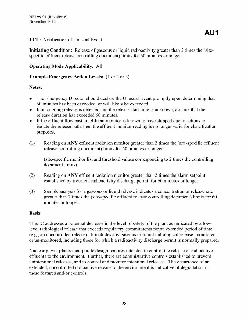
AU1 ECL: Notification of Unusual Event
Initiating Condition: Release of gaseous or liquid radioactivity greater than 2 times the (site-specific effluent release controlling document) limits for 60 minutes or longer.
Operating Mode Applicability: All
Example Emergency Action Levels: (1 or 2 or 3)
Notes: The Emergency Director should declare the Unusual Event promptly upon determining that
60 minutes has been exceeded, or will likely be exceeded. If an ongoing release is detected and the release start time is unknown, assume that the
release duration has exceeded 60 minutes. If the effluent flow past an effluent monitor is known to have stopped due to actions to
isolate the release path, then the effluent monitor reading is no longer valid for classification purposes.
(1) Reading on ANY effluent radiation monitor greater than 2 times the (site-specific effluent release controlling document) limits for 60 minutes or longer:
(site-specific monitor list and threshold values corresponding to 2 times the controlling document limits)
(2) Reading on ANY effluent radiation monitor greater than 2 times the alarm setpoint established by a current radioactivity discharge permit for 60 minutes or longer.
(3) Sample analysis for a gaseous or liquid release indicates a concentration or release rate greater than 2 times the (site-specific effluent release controlling document) limits for 60 minutes or longer.
Basis:
This IC addresses a potential decrease in the level of safety of the plant as indicated by a low-level radiological release that exceeds regulatory commitments for an extended period of time (e.g., an uncontrolled release). It includes any gaseous or liquid radiological release, monitored or un-monitored, including those for which a radioactivity discharge permit is normally prepared.
Nuclear power plants incorporate design features intended to control the release of radioactive effluents to the environment. Further, there are administrative controls established to prevent unintentional releases, and to control and monitor intentional releases. The occurrence of an extended, uncontrolled radioactive release to the environment is indicative of degradation in these features and/or controls.
NEI 99-01 (Revision 6) November 2012
29
Radiological effluent EALs are also included to provide a basis for classifying events and conditions that cannot be readily or appropriately classified on the basis of plant conditions alone. The inclusion of both plant condition and radiological effluent EALs more fully addresses the spectrum of possible accident events and conditions.
Classification based on effluent monitor readings assumes that a release path to the environment is established. If the effluent flow past an effluent monitor is known to have stopped due to actions to isolate the release path, then the effluent monitor reading is no longer valid for classification purposes.
Releases should not be prorated or averaged. For example, a release exceeding 4 times release limits for 30 minutes does not meet the EAL.
EAL #1 - This EAL addresses normally occurring continuous radioactivity releases from monitored gaseous or liquid effluent pathways.
EAL #2 - This EAL addresses radioactivity releases that cause effluent radiation monitor readings to exceed 2 times the limit established by a radioactivity discharge permit. This EAL will typically be associated with planned batch releases from non-continuous release pathways (e.g., radwaste, waste gas).
EAL #3 - This EAL addresses uncontrolled gaseous or liquid releases that are detected by sample analyses or environmental surveys, particularly on unmonitored pathways (e.g., spills of radioactive liquids into storm drains, heat exchanger leakage in river water systems, etc.).
Escalation of the emergency classification level would be via IC AA1.
Developer Notes:
The “site-specific effluent release controlling document” is the Radiological Effluent Technical Specifications (RETS) or, for plants that have implemented Generic Letter 89-014, the Offsite Dose Calculation Manual (ODCM). These documents implement regulations related to effluent controls (e.g., 10 CFR Part 20 and 10 CFR Part 50, Appendix I). As appropriate, the RETS or ODCM methodology should be used for establishing the monitor thresholds for this IC.
Listed monitors should include the effluent monitors described in the RETS or ODCM.
Developers may also consider including installed monitors associated with other potential effluent pathways that are not described in the RETS or ODCM56. If included, EAL values for these monitors should be determined using the most applicable dose/release limits presented in the RETS or ODCM. It is recognized that a calculated EAL value may be below what the monitor can read; in that case, the monitor does not need to be included in the list. Also, some monitors may not be governed by Technical Specifications or other license-related related 4 Implementation of Programmatic Controls for Radiological Effluent Technical Specifications in the Administrative Controls Section of the Technical Specifications and the Relocation of Procedural Details of RETS to the Offsite Dose Calculation Manual or to the Process Control Program 5 This includes consideration of the effluent monitors described in the site emergency plan section(s) which address the requirements of 10 CFR 50.47(b)(8) and (9). 6 Developers should keep in mind the requirements of 10 CFR 50.54(q) and the guidance provided by INPO related to emergency response equipment when considering the addition of other effluent monitors.
NEI 99-01 (Revision 6) November 2012
30
requirements; therefore, it is important that the associated EAL and basis section clearly identify any limitations on the use or availability of these monitors.
Some sites may find it advantageous to address gaseous and liquid releases with separate EALs.
Radiation monitor readings should reflect values that correspond to a radiological release exceeding 2 times a release control limit. The controlling document typically describes methodologies for determining effluent radiation monitor setpoints; these methodologies should be used to determine EAL values. In cases where a methodology is not adequately defined, developers should determine values consistent with effluent control regulations (e.g., 10 CFR Part 20 and 10 CFR Part 50 Appendix I) and related guidance. For EAL #2 - Values in this EAL should be 2 times the setpoint established by the radioactivity discharge permit to warn of a release that is not in compliance with the specified limits. Indexing the value in this manner ensures consistency between the EAL and the setpoint established by a specific discharge permit.
Developers should research radiation monitor design documents or other information sources to ensure that 1) the EAL value being considered is within the usable response and display range of the instrument, and 2) there are no automatic features that may render the monitor reading invalid (e.g., an auto-purge feature triggered at a particular indication level).
It is recognized that the condition described by this IC may result in a radiological effluent value beyond the operating or display range of the installed effluent monitor. In those cases, EAL values should be determined with a margin sufficient to ensure that an accurate monitor reading is available. For example, an EAL monitor reading might be set at 90% to 95% of the highest accurate monitor reading. This provision notwithstanding, if the estimated/calculated monitor reading is greater than approximately 110% of the highest accurate monitor reading, then developers may choose not to include the monitor as an indication and identify an alternate EAL threshold.
Indications from a real-time dose projection system are not included in the generic EALs. Many licensees do not have this capability. For those that do, the capability may not be within the scope of the plant Technical Specifications. A licensee may request to include an EAL using real-time dose projection system results; approval will be considered on a case-by-case basis.
Indications from a perimeter monitoring system are not included in the generic EALs. Many licensees do not have this capability. For those that do, these monitors may not be controlled and maintained to the same level as plant equipment, or within the scope of the plant Technical Specifications. In addition, readings may be influenced by environmental or other factors. A licensee may request to include an EAL using a perimeter monitoring system; approval will be considered on a case-by-case basis.
ECL Assignment Attributes: 3.1.1.B

NEI 99-01 (Revision 6) November 2012
31
AU2 ECL: Notification of Unusual Event
Initiating Condition: UNPLANNED loss of water level above irradiated fuel.
Operating Mode Applicability: All
Example Emergency Action Levels:
(1) a. UNPLANNED water level drop in the REFUELING PATHWAY as indicated by ANY of the following:
(site-specific level indications).
AND
b. UNPLANNED rise in area radiation levels as indicated by ANY of the following radiation monitors.
(site-specific list of area radiation monitors)
Basis:
This IC addresses a decrease in water level above irradiated fuel sufficient to cause elevated radiation levels. This condition could be a precursor to a more serious event and is also indicative of a minor loss in the ability to control radiation levels within the plant. It is therefore a potential degradation in the level of safety of the plant.
A water level decrease will be primarily determined by indications from available level instrumentation. Other sources of level indications may include reports from plant personnel (e.g., from a refueling crew) or video camera observations (if available). A significant drop in the water level may also cause an increase in the radiation levels of adjacent areas that can be detected by monitors in those locations.
The effects of planned evolutions should be considered. For example, a refueling bridge area radiation monitor reading may increase due to planned evolutions such as lifting of the reactor vessel head or movement of a fuel assembly. Note that this EAL is applicable only in cases where the elevated reading is due to an UNPLANNED loss of water level.
A drop in water level above irradiated fuel within the reactor vessel may be classified in accordance Recognition Category C during the Cold Shutdown and Refueling modes.
Escalation of the emergency classification level would be via IC AA2.
Developer Notes:
The “site-specific level indications” are those indications that may be used to monitor water level in the various portions of the REFUELING PATHWAY. Specify the mode applicability of a particular indication if it is not available in all modes.

NEI 99-01 (Revision 6) November 2012
32
The “site-specific list of area radiation monitors” should contain those area radiation monitors that would be expected to have increased readings following a decrease in water level in the site-specific REFUELING PATHWAY. In cases where a radiation monitor(s) is not available or would not provide a useful indication, consideration should be given to including alternate indications such as UNPLANNED changes in tank and/or sump levels.
Development of the EALs should consider the availability and limitations of mode-dependent, or other controlled but temporary, radiation monitors. Specify the mode applicability of a particular monitor if it is not available in all modes.
ECL Assignment Attributes: 3.1.1.A and 3.1.1.B

NEI 99-01 (Revision 6) November 2012
33
AA1
ECL: Alert
Initiating Condition: Release of gaseous or liquid radioactivity resulting in offsite dose greater than 10 mrem TEDE or 50 mrem thyroid CDE.
Operating Mode Applicability: All
Example Emergency Action Levels: (1 or 2 or 3 or 4)
Notes: The Emergency Director should declare the Alert promptly upon determining that the
applicable time has been exceeded, or will likely be exceeded. If an ongoing release is detected and the release start time is unknown, assume that the
release duration has exceeded 15 minutes. If the effluent flow past an effluent monitor is known to have stopped due to actions to
isolate the release path, then the effluent monitor reading is no longer valid for classification purposes.
The pre-calculated effluent monitor values presented in EAL #1 should be used for emergency classification assessments until the results from a dose assessment using actual meteorology are available.
(1) Reading on ANY of the following radiation monitors greater than the reading shown for
15 minutes or longer:
(site-specific monitor list and threshold values)
(2) Dose assessment using actual meteorology indicates doses greater than 10 mrem TEDE or 50 mrem thyroid CDE at or beyond (site-specific dose receptor point).
(3) Analysis of a liquid effluent sample indicates a concentration or release rate that would result in doses greater than 10 mrem TEDE or 50 mrem thyroid CDE at or beyond (site-specific dose receptor point) for one hour of exposure.
(4) Field survey results indicate EITHER of the following at or beyond (site-specific dose receptor point):
Closed window dose rates greater than 10 mR/hr expected to continue for 60 minutes or longer.
Analyses of field survey samples indicate thyroid CDE greater than 50 mrem for one hour of inhalation.
Basis:
This IC addresses a release of gaseous or liquid radioactivity that results in projected or actual offsite doses greater than or equal to 1% of the EPA Protective Action Guides (PAGs). It includes both monitored and un-monitored releases. Releases of this magnitude represent an
NEI 99-01 (Revision 6) November 2012
34
actual or potential substantial degradation of the level of safety of the plant as indicated by a radiological release that significantly exceeds regulatory limits (e.g., a significant uncontrolled release). Radiological effluent EALs are also included to provide a basis for classifying events and conditions that cannot be readily or appropriately classified on the basis of plant conditions alone. The inclusion of both plant condition and radiological effluent EALs more fully addresses the spectrum of possible accident events and conditions.
The TEDE dose is set at 1% of the EPA PAG of 1,000 mrem while the 50 mrem thyroid CDE was established in consideration of the 1:5 ratio of the EPA PAG for TEDE and thyroid CDE.
Classification based on effluent monitor readings assumes that a release path to the environment is established. If the effluent flow past an effluent monitor is known to have stopped due to actions to isolate the release path, then the effluent monitor reading is no longer valid for classification purposes.
Escalation of the emergency classification level would be via IC AS1.
Developer Notes:
While this IC may not be met absent challenges to one or more fission product barriers, it provides classification diversity and may be used to classify events that would not reach the same ECL based on plant status or the fission product matrix alone. For many of the DBAs analyzed in the Updated Final Safety Analysis Report, the discriminator will not be the number of fission product barriers challenged, but rather the amount of radioactivity released to the environment.
The EPA PAGs are expressed in terms of the sum of the effective dose equivalent (EDE) and the committed effective dose equivalent (CEDE), or as the thyroid committed dose equivalent (CDE). For the purpose of these IC/EALs, the dose quantity total effective dose equivalent (TEDE), as defined in 10 CFR § 20, is used in lieu of “…sum of EDE and CEDE.…”.
The EPA PAG guidance provides for the use of adult thyroid dose conversion factors; however, some states have decided to base protective actions on child thyroid CDE. Nuclear power plant ICs/EALs need to be consistent with the protective action methodologies employed by the States within their EPZs. The thyroid CDE dose used in the IC and EALs should be adjusted as necessary to align with State protective action decision-making criteria.
The “site-specific monitor list and threshold values” should be determined with consideration of the following:
Selection of the appropriate installed gaseous and liquid effluent monitors. The effluent monitor readings should correspond to a dose of 10 mrem TEDE or 50 mrem
thyroid CDE at the “site-specific dose receptor point” (consistent with the calculation methodology employed) for one hour of exposure.
Monitor readings will be calculated using a set of assumed meteorological data or atmospheric dispersion factors; the data or factors selected for use should be the same as those employed to calculate the monitor readings for ICs AS1 and AG1. Acceptable sources

NEI 99-01 (Revision 6) November 2012
35
of this information include, but are not limited to, the RETS/ODCM and values used in the site’s emergency dose assessment methodology.
The calculation of monitor readings will also require use of an assumed release isotopic mix; the selected mix should be the same as that employed to calculate monitor readings for ICs AS1 and AG1. Acceptable sources of this information include, but are not limited to, the RETS/ODCM and values used in the site’s emergency dose assessment methodology.
Depending upon the methodology used to calculate the EAL values, there may be overlap of some values between different ICs. Developers will need to address this overlap by adjusting these values in a manner that ensures a logical escalation in the ECL.
The “site-specific dose receptor point” is the distance(s) and/or locations used by the licensee to distinguish between on-site and offsite doses. The selected distance(s) and/or locations should reflect the content of the emergency plan, and the procedural methodology used to determine offsite doses and Protective Action Recommendations. The variation in selected dose receptor points means there may be some differences in the distance from the release point to the calculated dose point from site to site.
Developers should research radiation monitor design documents or other information sources to ensure that 1) the EAL value being considered is within the usable response and display range of the instrument, and 2) there are no automatic features that may render the monitor reading invalid (e.g., an auto-purge feature triggered at a particular indication level).
It is recognized that the condition described by this IC may result in a radiological effluent value beyond the operating or display range of the installed effluent monitor. In those cases, EAL values should be determined with a margin sufficient to ensure that an accurate monitor reading is available. For example, an EAL monitor reading might be set at 90% to 95% of the highest accurate monitor reading. This provision notwithstanding, if the estimated/calculated monitor reading is greater than approximately 110% of the highest accurate monitor reading, then developers may choose not to include the monitor as an indication and identify an alternate EAL threshold.
Although the IC references TEDE, field survey results are generally available only as a “whole body” dose rate. For this reason, the field survey EAL specifies a “closed window” survey reading.
Indications from a real-time dose projection system are not included in the generic EALs. Many licensees do not have this capability. For those that do, the capability may not be within the scope of the plant Technical Specifications. A licensee may request to include an EAL using real-time dose projection system results; approval will be considered on a case-by-case basis.
Indications from a perimeter monitoring system are not included in the generic EALs. Many licensees do not have this capability. For those that do, these monitors may not be controlled and maintained to the same level as plant equipment, or within the scope of the plant Technical Specifications. In addition, readings may be influenced by environmental or other factors. A licensee may request to include an EAL using a perimeter monitoring system; approval will be considered on a case-by-case basis.
ECL Assignment Attributes: 3.1.2.C

NEI 99-01 (Revision 6) November 2012
36
AA2 ECL: Alert
Initiating Condition: Significant lowering of water level above, or damage to, irradiated fuel.
Operating Mode Applicability: All
Example Emergency Action Levels: (1 or 2 or 3)
(1) Uncovery of irradiated fuel in the REFUELING PATHWAY.
(2) Damage to irradiated fuel resulting in a release of radioactivity from the fuel as indicated by ANY of the following radiation monitors:
(site-specific listing of radiation monitors, and the associated readings, setpoints and/or alarms)
(3) Lowering of spent fuel pool level to (site-specific Level 2 value). [See Developer Notes]
Basis:
This IC addresses events that have caused IMMINENT or actual damage to an irradiated fuel assembly, or a significant lowering of water level within the spent fuel pool (see Developer Notes). These events present radiological safety challenges to plant personnel and are precursors to a release of radioactivity to the environment. As such, they represent an actual or potential substantial degradation of the level of safety of the plant.
This IC applies to irradiated fuel that is licensed for dry storage up to the point that the loaded storage cask is sealed. Once sealed, damage to a loaded cask causing loss of the CONFINEMENT BOUNDARY is classified in accordance with IC E-HU1.
Escalation of the emergency would be based on either Recognition Category A or C ICs.
EAL #1
This EAL escalates from AU2 in that the loss of level, in the affected portion of the REFUELING PATHWAY, is of sufficient magnitude to have resulted in uncovery of irradiated fuel. Indications of irradiated fuel uncovery may include direct or indirect visual observation (e.g., reports from personnel or camera images), as well as significant changes in water and radiation levels, or other plant parameters. Computational aids may also be used (e.g., a boil-off curve). Classification of an event using this EAL should be based on the totality of available indications, reports and observations.
While an area radiation monitor could detect an increase in a dose rate due to a lowering of water level in some portion of the REFUELING PATHWAY, the reading may not be a reliable indication of whether or not the fuel is actually uncovered. To the degree possible, readings should be considered in combination with other available indications of inventory loss.
A drop in water level above irradiated fuel within the reactor vessel may be classified in accordance Recognition Category C during the Cold Shutdown and Refueling modes.

NEI 99-01 (Revision 6) November 2012
37
EAL #2
This EAL addresses a release of radioactive material caused by mechanical damage to irradiated fuel. Damaging events may include the dropping, bumping or binding of an assembly, or dropping a heavy load onto an assembly. A rise in readings on radiation monitors should be considered in conjunction with in-plant reports or observations of a potential fuel damaging event (e.g., a fuel handling accident).
EAL #3
Spent fuel pool water level at this value is within the lower end of the level range necessary to prevent significant dose consequences from direct gamma radiation to personnel performing operations in the vicinity of the spent fuel pool. This condition reflects a significant loss of spent fuel pool water inventory and thus it is also a precursor to a loss of the ability to adequately cool the irradiated fuel assembles stored in the pool.
Escalation of the emergency classification level would be via ICs AS1 or AS2 (see AS2 Developer Notes).
Developer Notes:
For EAL #1
Depending upon the availability and range of instrumentation, this EAL may include specific readings indicative of fuel uncovery; consider water and radiation level readings. Specify the mode applicability of a particular indication if it is not available in all modes.
For EAL #2
The “site-specific listing of radiation monitors, and the associated readings, setpoints and/or alarms” should contain those radiation monitors that could be used to identify damage to an irradiated fuel assembly (e.g., confirmatory of a release of fission product gases from irradiated fuel).
For EALs #1 and #2
Developers should research radiation monitor design documents or other information sources to ensure that 1) the EAL value being considered is within the usable response and display range of the instrument, and 2) there are no automatic features that may render the monitor reading invalid (e.g., an auto-purge feature triggered at a particular indication level).
It is recognized that the condition described by this IC may result in a radiation value beyond the operating or display range of the installed radiation monitor. In those cases, EAL values should be determined with a margin sufficient to ensure that an accurate monitor reading is available. For example, an EAL monitor reading might be set at 90% to 95% of the highest accurate monitor reading. This provision notwithstanding, if the estimated/calculated monitor reading is greater than approximately 110% of the highest accurate monitor reading, then developers may choose not to include the monitor as an indication and identify an alternate EAL threshold.

NEI 99-01 (Revision 6) November 2012
38
To further promote accurate classification, developers should consider if some combination of monitors could be specified in the EAL to build-in an appropriate level of corroboration between monitor readings into the classification assessment.
Development of the EALs should also consider the availability and limitations of mode-dependent, or other controlled but temporary, radiation monitors. Specify the mode applicability of a particular monitor if it is not available in all modes.
For EAL #3
In accordance with the discussion in Section 1.4, NRC Order EA-12-051, it is recommended that this EAL be implemented when the enhanced spent fuel pool level instrumentation is available for use. The “site-specific Level 2 value” is usually the spent fuel pool level that is adequate to provide substantial radiation shielding for a person standing on the spent fuel pool operating deck. This site-specific level is determined in accordance with NRC Order EA-12-051 and NEI 12-02, and applicable owner’s group guidance.
Developers should modify the EAL and/or Basis section to reflect any site-specific constraints or limitations associated with the design or operation of instrumentation used to determine the Level 2 value.
ECL Assignment Attributes: 3.1.2.B and 3.1.2.C

NEI 99-01 (Revision 6) November 2012
39
AA3
ECL: Alert
Initiating Condition: Radiation levels that impede access to equipment necessary for normal plant operations, cooldown or shutdown.
Operating Mode Applicability: All
Example Emergency Action Levels: (1 or 2)
Note: If the equipment in the listed room or area was already inoperable or out-of-service before the event occurred, then no emergency classification is warranted.
(1) Dose rate greater than 15 mR/hr in ANY of the following areas:
Control Room Central Alarm Station (other site-specific areas/rooms)
(2) An UNPLANNED event results in radiation levels that prohibit or impede access to any of the following plant rooms or areas:
(site-specific list of plant rooms or areas with entry-related mode applicability identified)
Basis:
This IC addresses elevated radiation levels in certain plant rooms/areas sufficient to preclude or impede personnel from performing actions necessary to maintain normal plant operation, or to perform a normal plant cooldown and shutdown. As such, it represents an actual or potential substantial degradation of the level of safety of the plant. The Emergency Director should consider the cause of the increased radiation levels and determine if another IC may be applicable.
For EAL #2, an Alert declaration is warranted if entry into the affected room/area is, or may be, procedurally required during the plant operating mode in effect at the time of the elevated radiation levels. The emergency classification is not contingent upon whether entry is actually necessary at the time of the increased radiation levels. Access should be considered as impeded if extraordinary measures are necessary to facilitate entry of personnel into the affected room/area (e.g., installing temporary shielding, requiring use of non-routine protective equipment, requesting an extension in dose limits beyond normal administrative limits).
An emergency declaration is not warranted if any of the following conditions apply.
The plant is in an operating mode different than the mode specified for the affected room/area (i.e., entry is not required during the operating mode in effect at the time of the elevated radiation levels). For example, the plant is in Mode 1 when the radiation increase occurs, and the procedures used for normal operation, cooldown and shutdown do not require entry into the affected room until Mode 4.

NEI 99-01 (Revision 6) November 2012
40
The increased radiation levels are a result of a planned activity that includes compensatory measures which address the temporary inaccessibility of a room or area (e.g., radiography, spent filter or resin transfer, etc.).
The action for which room/area entry is required is of an administrative or record keeping nature (e.g., normal rounds or routine inspections).
The access control measures are of a conservative or precautionary nature, and would not actually prevent or impede a required action.
Escalation of the emergency classification level would be via Recognition Category A, C or F ICs.
Developer Notes:
EAL #1
The value of 15mR/hr is derived from the GDC 19 value of 5 rem in 30 days with adjustment for expected occupancy times.
The “other site-specific areas/rooms” should include any areas or rooms requiring continuous occupancy to maintain normal plant operation, or to perform a normal cooldown and shutdown.
EAL #2
The “site-specific list of plant rooms or areas with entry-related mode applicability identified” should specify those rooms or areas that contain equipment which require a manual/local action as specified in operating procedures used for normal plant operation, cooldown and shutdown. Do not include rooms or areas in which actions of a contingent or emergency nature would be performed. (e.g., an action to address an off-normal or emergency condition such as emergency repairs, corrective measures or emergency operations). In addition, the list should specify the plant mode(s) during which entry would be required for each room or area.
The list should not include rooms or areas for which entry is required solely to perform actions of an administrative or record keeping nature (e.g., normal rounds or routine inspections). If the equipment in the listed room or area was already inoperable, or out-of-service, before the event occurred, then no emergency should be declared since the event will have no adverse impact beyond that already allowed by Technical Specifications at the time of the event.
Rooms and areas listed in EAL #1 do not need to be included in EAL #2, including the Control Room.
ECL Assignment Attributes: 3.1.2.C

NEI 99-01 (Revision 6) November 2012
41
AS1 ECL: Site Area Emergency
Initiating Condition: Release of gaseous radioactivity resulting in offsite dose greater than 100 mrem TEDE or 500 mrem thyroid CDE.
Operating Mode Applicability: All
Example Emergency Action Levels: (1 or 2 or 3)
Notes: The Emergency Director should declare the Site Area Emergency promptly upon
determining that the applicable time has been exceeded, or will likely be exceeded. If an ongoing release is detected and the release start time is unknown, assume that the
release duration has exceeded 15 minutes. If the effluent flow past an effluent monitor is known to have stopped due to actions to
isolate the release path, then the effluent monitor reading is no longer valid for classification purposes.
The pre-calculated effluent monitor values presented in EAL #1 should be used for emergency classification assessments until the results from a dose assessment using actual meteorology are available.
(1) Reading on ANY of the following radiation monitors greater than the reading shown for
15 minutes or longer:
(site-specific monitor list and threshold values)
(2) Dose assessment using actual meteorology indicates doses greater than 100 mrem TEDE or 500 mrem thyroid CDE at or beyond (site-specific dose receptor point).
(3) Field survey results indicate EITHER of the following at or beyond (site-specific dose receptor point):
Closed window dose rates greater than 100 mR/hr expected to continue for 60 minutes or longer.
Analyses of field survey samples indicate thyroid CDE greater than 500 mrem for one hour of inhalation.
Basis:
This IC addresses a release of gaseous radioactivity that results in projected or actual offsite doses greater than or equal to 10% of the EPA Protective Action Guides (PAGs). It includes both monitored and un-monitored releases. Releases of this magnitude are associated with the failure of plant systems needed for the protection of the public.
Radiological effluent EALs are also included to provide a basis for classifying events and conditions that cannot be readily or appropriately classified on the basis of plant conditions alone. The inclusion of both plant condition and radiological effluent EALs more fully addresses
NEI 99-01 (Revision 6) November 2012
42
the spectrum of possible accident events and conditions.
The TEDE dose is set at 10% of the EPA PAG of 1,000 mrem while the 500 mrem thyroid CDE was established in consideration of the 1:5 ratio of the EPA PAG for TEDE and thyroid CDE.
Classification based on effluent monitor readings assumes that a release path to the environment is established. If the effluent flow past an effluent monitor is known to have stopped due to actions to isolate the release path, then the effluent monitor reading is no longer valid for classification purposes.
Escalation of the emergency classification level would be via IC AG1.
Developer Notes:
While this IC may not be met absent challenges to multiple fission product barriers, it provides classification diversity and may be used to classify events that would not reach the same ECL based on plant status or the fission product matrix alone. For many of the DBAs analyzed in the Updated Final Safety Analysis Report, the discriminator will not be the number of fission product barriers challenged, but rather the amount of radioactivity released to the environment.
The EPA PAGs are expressed in terms of the sum of the effective dose equivalent (EDE) and the committed effective dose equivalent (CEDE), or as the thyroid committed dose equivalent (CDE). For the purpose of these IC/EALs, the dose quantity total effective dose equivalent (TEDE), as defined in 10 CFR § 20, is used in lieu of “…sum of EDE and CEDE.…”.
The EPA PAG guidance provides for the use of adult thyroid dose conversion factors; however, some states have decided to base protective actions on child thyroid CDE. Nuclear power plant ICs/EALs need to be consistent with the protective action methodologies employed by the States within their EPZs. The thyroid CDE dose used in the IC and EALs should be adjusted as necessary to align with State protective action decision-making criteria.
The “site-specific monitor list and threshold values” should be determined with consideration of the following:
Selection of the appropriate installed gaseous effluent monitors. The effluent monitor readings should correspond to a dose of 100 mrem TEDE or 500 mrem
thyroid CDE at the “site-specific dose receptor point” (consistent with the calculation methodology employed) for one hour of exposure.
Monitor readings will be calculated using a set of assumed meteorological data or atmospheric dispersion factors; the data or factors selected for use should be the same as those employed to calculate the monitor readings for ICs AA1 and AG1. Acceptable sources of this information include, but are not limited to, the RETS/ODCM and values used in the site’s emergency dose assessment methodology.
The calculation of monitor readings will also require use of an assumed release isotopic mix; the selected mix should be the same as that employed to calculate monitor readings for ICs AA1 and AG1. Acceptable sources of this information include, but are not limited to, the RETS/ODCM and values used in the site’s emergency dose assessment methodology.

NEI 99-01 (Revision 6) November 2012
43
Depending upon the methodology used to calculate the EAL values, there may be overlap of some values between different ICs. Developers will need to address this overlap by adjusting these values in a manner that ensures a logical escalation in the ECL.
The “site-specific dose receptor point” is the distance(s) and/or locations used by the licensee to distinguish between on-site and offsite doses. The selected distance(s) and/or locations should reflect the content of the emergency plan, and the procedural methodology used to determine offsite doses and Protective Action Recommendations. The variation in selected dose receptor points means there may be some differences in the distance from the release point to the calculated dose point from site to site.
Developers should research radiation monitor design documents or other information sources to ensure that 1) the EAL value being considered is within the usable response and display range of the instrument, and 2) there are no automatic features that may render the monitor reading invalid (e.g., an auto-purge feature triggered at a particular indication level).
It is recognized that the condition described by this IC may result in a radiological effluent value beyond the operating or display range of the installed effluent monitor. In those cases, EAL values should be determined with a margin sufficient to ensure that an accurate monitor reading is available. For example, an EAL monitor reading might be set at 90% to 95% of the highest accurate monitor reading. This provision notwithstanding, if the estimated/calculated monitor reading is greater than approximately 110% of the highest accurate monitor reading, then developers may choose not to include the monitor as an indication and identify an alternate EAL threshold.
Although the IC references TEDE, field survey results are generally available only as a “whole body” dose rate. For this reason, the field survey EAL specifies a “closed window” survey reading.
Indications from a real-time dose projection system are not included in the generic EALs. Many licensees do not have this capability. For those that do, the capability may not be within the scope of the plant Technical Specifications. A licensee may request to include an EAL using real-time dose projection system results; approval will be considered on a case-by-case basis.
Indications from a perimeter monitoring system are not included in the generic EALs. Many licensees do not have this capability. For those that do, these monitors may not be controlled and maintained to the same level as plant equipment, or within the scope of the plant Technical Specifications. In addition, readings may be influenced by environmental or other factors. A licensee may request to include an EAL using a perimeter monitoring system; approval will be considered on a case-by-case basis.
ECL Assignment Attributes: 3.1.3.C

NEI 99-01 (Revision 6) November 2012
44
AS2
[See Developer Notes] ECL: Site Area Emergency
Initiating Condition: Spent fuel pool level at (site-specific Level 3 description).
Operating Mode Applicability: All
Example Emergency Action Levels:
(1) Lowering of spent fuel pool level to (site-specific Level 3 value).
Basis:
This IC addresses a significant loss of spent fuel pool inventory control and makeup capability leading to IMMINENT fuel damage. This condition entails major failures of plant functions needed for protection of the public and thus warrant a Site Area Emergency declaration.
It is recognized that this IC would likely not be met until well after another Site Area Emergency IC was met; however, it is included to provide classification diversity.
Escalation of the emergency classification level would be via IC AG1 or AG2.
Developer Notes:
In accordance with the discussion in Section 1.4, NRC Order EA-12-051, it is recommended that this IC and EAL be implemented when the enhanced spent fuel pool level instrumentation is available for use. The “site-specific Level 3 value” is usually that spent fuel pool level where fuel remains covered and actions to implement make-up water addition should no longer be deferred. This site-specific level is determined in accordance with NRC Order EA-12-051 and NEI 12-02, and applicable owner’s group guidance.
Developers should modify the EAL and/or Basis section to reflect any site-specific constraints or limitations associated with the design or operation of instrumentation used to determine the Level 3 value.
ECL Assignment Attributes: 3.1.3.B

NEI 99-01 (Revision 6) November 2012
45
AG1 ECL: General Emergency
Initiating Condition: Release of gaseous radioactivity resulting in offsite dose greater than 1,000 mrem TEDE or 5,000 mrem thyroid CDE.
Operating Mode Applicability: All
Example Emergency Action Levels: (1 or 2 or 3)
Notes: The Emergency Director should declare the General Emergency promptly upon determining
that the applicable time has been exceeded, or will likely be exceeded. If an ongoing release is detected and the release start time is unknown, assume that the
release duration has exceeded 15 minutes. If the effluent flow past an effluent monitor is known to have stopped due to actions to
isolate the release path, then the effluent monitor reading is no longer valid for classification purposes.
The pre-calculated effluent monitor values presented in EAL #1 should be used for emergency classification assessments until the results from a dose assessment using actual meteorology are available.
(1) Reading on ANY of the following radiation monitors greater than the reading shown for
15 minutes or longer:
(site-specific monitor list and threshold values)
(2) Dose assessment using actual meteorology indicates doses greater than 1,000 mrem TEDE or 5,000 mrem thyroid CDE at or beyond (site-specific dose receptor point).
(3) Field survey results indicate EITHER of the following at or beyond (site-specific dose receptor point):
Closed window dose rates greater than 1,000 mR/hr expected to continue for 60 minutes or longer.
Analyses of field survey samples indicate thyroid CDE greater than 5,000 mrem for one hour of inhalation.
Basis:
This IC addresses a release of gaseous radioactivity that results in projected or actual offsite doses greater than or equal to the EPA Protective Action Guides (PAGs). It includes both monitored and un-monitored releases. Releases of this magnitude will require implementation of protective actions for the public.
Radiological effluent EALs are also included to provide a basis for classifying events and conditions that cannot be readily or appropriately classified on the basis of plant conditions

NEI 99-01 (Revision 6) November 2012
46
alone. The inclusion of both plant condition and radiological effluent EALs more fully addresses the spectrum of possible accident events and conditions.
The TEDE dose is set at the EPA PAG of 1,000 mrem while the 5,000 mrem thyroid CDE was established in consideration of the 1:5 ratio of the EPA PAG for TEDE and thyroid CDE.
Classification based on effluent monitor readings assumes that a release path to the environment is established. If the effluent flow past an effluent monitor is known to have stopped due to actions to isolate the release path, then the effluent monitor reading is no longer valid for classification purposes.
Developer Notes:
The effluent ICs/EALs are included to provide a basis for classifying events that cannot be readily classified on the basis of plant conditions alone. The inclusion of both types of ICs/EALs more fully addresses the spectrum of possible events and accidents.
While this IC may not be met absent challenges to multiple fission product barriers, it provides classification diversity and may be used to classify events that would not reach the same ECL based on plant status or the fission product matrix alone. For many of the DBAs analyzed in the Updated Final Safety Analysis Report, the discriminator will not be the number of fission product barriers challenged, but rather the amount of radioactivity released to the environment.
The EPA PAGs are expressed in terms of the sum of the effective dose equivalent (EDE) and the committed effective dose equivalent (CEDE), or as the thyroid committed dose equivalent (CDE). For the purpose of these IC/EALs, the dose quantity total effective dose equivalent (TEDE), as defined in 10 CFR § 20, is used in lieu of “…sum of EDE and CEDE.…”.
The EPA PAG guidance provides for the use of adult thyroid dose conversion factors; however, some states have decided to base protective actions on child thyroid CDE. Nuclear power plant ICs/EALs need to be consistent with the protective action methodologies employed by the States within their EPZs. The thyroid CDE dose used in the IC and EALs should be adjusted as necessary to align with State protective action decision-making criteria.
The “site-specific monitor list and threshold values” should be determined with consideration of the following:
Selection of the appropriate installed gaseous effluent monitors. The effluent monitor readings should correspond to a dose of 1,000 mrem TEDE or 5,000
mrem thyroid CDE at the “site-specific dose receptor point” (consistent with the calculation methodology employed) for one hour of exposure.
Monitor readings will be calculated using a set of assumed meteorological data or atmospheric dispersion factors; the data or factors selected for use should be the same as those employed to calculate the monitor readings for ICs AA1 and AS1. Acceptable sources of this information include, but are not limited to, the RETS/ODCM and values used in the site’s emergency dose assessment methodology.
The calculation of monitor readings will also require use of an assumed release isotopic mix; the selected mix should be the same as that employed to calculate monitor readings for ICs AA1 and AS1. Acceptable sources of this information include, but are not limited to, the

NEI 99-01 (Revision 6) November 2012
47
RETS/ODCM and values used in the site’s emergency dose assessment methodology. Depending upon the methodology used to calculate the EAL values, there may be overlap of
some values between different ICs. Developers will need to address this overlap by adjusting these values in a manner that ensures a logical escalation in the ECL.
The “site-specific dose receptor point” is the distance(s) and/or locations used by the licensee to distinguish between on-site and offsite doses. The selected distance(s) and/or locations should reflect the content of the emergency plan, and procedural methodology used to determine offsite doses and Protective Action Recommendations. The variation in selected dose receptor points means there may be some differences in the distance from the release point to the calculated dose point from site to site.
Developers should research radiation monitor design documents or other information sources to ensure that 1) the EAL value being considered is within the usable response and display range of the instrument, and 2) there are no automatic features that may render the monitor reading invalid (e.g., an auto-purge feature triggered at a particular indication level).
It is recognized that the condition described by this IC may result in a radiological effluent value beyond the operating or display range of the installed effluent monitor. In those cases, EAL values should be determined with a margin sufficient to ensure that an accurate monitor reading is available. For example, an EAL monitor reading might be set at 90% to 95% of the highest accurate monitor reading. This provision notwithstanding, if the estimated/calculated monitor reading is greater than approximately 110% of the highest accurate monitor reading, then developers may choose not to include the monitor as an indication and identify an alternate EAL threshold.
Although the IC references TEDE, field survey results are generally available only as a “whole body” dose rate. For this reason, the field survey EAL specifies a “closed window” survey reading.
Indications from a real-time dose projection system are not included in the generic EALs. Many licensees do not have this capability. For those that do, the capability may not be within the scope of the plant Technical Specifications. A licensee may request to include an EAL using real-time dose projection system results; approval will be considered on a case-by-case basis.
Indications from a perimeter monitoring system are not included in the generic EALs. Many licensees do not have this capability. For those that do, these monitors may not be controlled and maintained to the same level as plant equipment, or within the scope of the plant Technical Specifications. In addition, readings may be influenced by environmental or other factors. A licensee may request to include an EAL using a perimeter monitoring system; approval will be considered on a case-by-case basis.
ECL Assignment Attributes: 3.1.4.C
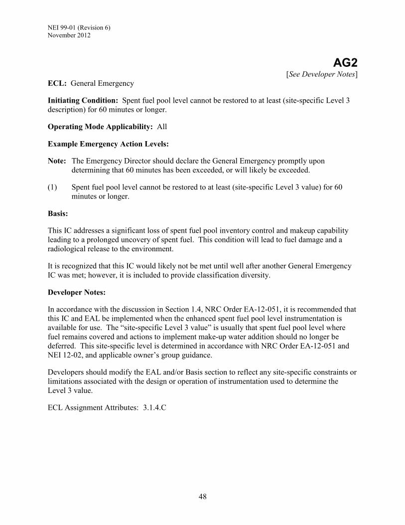
NEI 99-01 (Revision 6) November 2012
48
AG2
[See Developer Notes] ECL: General Emergency
Initiating Condition: Spent fuel pool level cannot be restored to at least (site-specific Level 3 description) for 60 minutes or longer.
Operating Mode Applicability: All
Example Emergency Action Levels:
Note: The Emergency Director should declare the General Emergency promptly upon determining that 60 minutes has been exceeded, or will likely be exceeded.
(1) Spent fuel pool level cannot be restored to at least (site-specific Level 3 value) for 60 minutes or longer.
Basis:
This IC addresses a significant loss of spent fuel pool inventory control and makeup capability leading to a prolonged uncovery of spent fuel. This condition will lead to fuel damage and a radiological release to the environment.
It is recognized that this IC would likely not be met until well after another General Emergency IC was met; however, it is included to provide classification diversity.
Developer Notes:
In accordance with the discussion in Section 1.4, NRC Order EA-12-051, it is recommended that this IC and EAL be implemented when the enhanced spent fuel pool level instrumentation is available for use. The “site-specific Level 3 value” is usually that spent fuel pool level where fuel remains covered and actions to implement make-up water addition should no longer be deferred. This site-specific level is determined in accordance with NRC Order EA-12-051 and NEI 12-02, and applicable owner’s group guidance.
Developers should modify the EAL and/or Basis section to reflect any site-specific constraints or limitations associated with the design or operation of instrumentation used to determine the Level 3 value.
ECL Assignment Attributes: 3.1.4.C

NEI 99-01 (Revision 6) November 2012
49
7 COLD SHUTDOWN / REFUELING SYSTEM MALFUNCTION ICS/EALS
Table C-1: Recognition Category “C” Initiating Condition Matrix
UNUSUAL EVENT ALERT SITE AREA EMERGENCY
GENERAL EMERGENCY
CU1 UNPLANNED loss of (reactor vessel/RCS [PWR] or RPV [BWR]) inventory for 15 minutes or longer. Op. Modes: Cold Shutdown, Refueling
CA1 Loss of (reactor vessel/RCS [PWR] or RPV [BWR]) inventory. Op. Modes: Cold Shutdown, Refueling
CS1 Loss of (reactor vessel/RCS [PWR] or RPV [BWR]) inventory affecting core decay heat removal capability. Op. Modes: Cold Shutdown, Refueling
CG1 Loss of (reactor vessel/RCS [PWR] or RPV [BWR]) inventory affecting fuel clad integrity with containment challenged. Op. Modes: Cold Shutdown, Refueling
CU2 Loss of all but one AC power source to emergency buses for 15 minutes or longer. Op. Modes: Cold Shutdown, Refueling, Defueled
CA2 Loss of all offsite and all onsite AC power to emergency buses for 15 minutes or longer. Op. Modes: Cold Shutdown, Refueling, Defueled
CU3 UNPLANNED increase in RCS temperature. Op. Modes: Cold Shutdown, Refueling
CA3 Inability to maintain the plant in cold shutdown. Op. Modes: Cold Shutdown, Refueling
CU4 Loss of Vital DC power for 15 minutes or longer. Op. Modes: Cold Shutdown, Refueling
CU5 Loss of all onsite or offsite communications capabilities. Op. Modes: Cold Shutdown, Refueling, Defueled
Table intended for use by EAL developers. Inclusion in licensee documents is not required.

NEI 99-01 (Revision 6) November 2012
50
UNUSUAL EVENT ALERT SITE AREA EMERGENCY
GENERAL EMERGENCY
CA6 Hazardous event affecting a SAFETY SYSTEM needed for the current operating mode. Op. Modes: Cold Shutdown, Refueling
Table intended for use by EAL developers. Inclusion in licensee documents is not required.

NEI 99-01 (Revision 6) November 2012
51
CU1 ECL: Notification of Unusual Event
Initiating Condition: UNPLANNED loss of (reactor vessel/RCS [PWR] or RPV [BWR]) inventory for 15 minutes or longer.
Operating Mode Applicability: Cold Shutdown, Refueling
Example Emergency Action Levels: (1 or 2)
Note: The Emergency Director should declare the Unusual Event promptly upon determining that 15 minutes has been exceeded, or will likely be exceeded.
(1) UNPLANNED loss of reactor coolant results in (reactor vessel/RCS [PWR] or RPV [BWR]) level less than a required lower limit for 15 minutes or longer.
(2) a. (Reactor vessel/RCS [PWR] or RPV [BWR]) level cannot be monitored.
AND
b. UNPLANNED increase in (site-specific sump and/or tank) levels.
Basis:
This IC addresses the inability to restore and maintain water level to a required minimum level (or the lower limit of a level band), or a loss of the ability to monitor (reactor vessel/RCS [PWR] or RPV [BWR]) level concurrent with indications of coolant leakage. Either of these conditions is considered to be a potential degradation of the level of safety of the plant.
Refueling evolutions that decrease RCS water inventory are carefully planned and controlled. An UNPLANNED event that results in water level decreasing below a procedurally required limit warrants the declaration of an Unusual Event due to the reduced water inventory that is available to keep the core covered.
EAL #1 recognizes that the minimum required (reactor vessel/RCS [PWR] or RPV [BWR]) level can change several times during the course of a refueling outage as different plant configurations and system lineups are implemented. This EAL is met if the minimum level, specified for the current plant conditions, cannot be maintained for 15 minutes or longer. The minimum level is typically specified in the applicable operating procedure but may be specified in another controlling document.
The 15-minute threshold duration allows sufficient time for prompt operator actions to restore and maintain the expected water level. This criterion excludes transient conditions causing a brief lowering of water level.
EAL #2 addresses a condition where all means to determine (reactor vessel/RCS [PWR] or RPV [BWR]) level have been lost. In this condition, operators may determine that an inventory loss is occurring by observing changes in sump and/or tank levels. Sump and/or tank level changes must be evaluated against other potential sources of water flow to ensure they are indicative of leakage from the (reactor vessel/RCS [PWR] or RPV [BWR]).

NEI 99-01 (Revision 6) November 2012
52
Continued loss of RCS inventory may result in escalation to the Alert emergency classification level via either IC CA1 or CA3.
Developer Notes:
EAL #1 – It is recognized that the minimum allowable reactor vessel/RCS/RPV level may have many values over the course of a refueling outage. Developers should solicit input from licensed operators concerning the optimum wording for this EAL statement. In particular, determine if the generic wording is adequate to ensure accurate and timely classification, or if specific setpoints can be included without making the EAL statement unwieldy or potentially inconsistent with actions that may be taken during an outage. If specific setpoints are included, these should be drawn from applicable operating procedures or other controlling documents.
EAL #2.b – Enter any “site-specific sump and/or tank” levels that could be expected to increase if there were a loss of inventory (i.e., the lost inventory would enter the listed sump or tank).
ECL Assignment Attributes: 3.1.1.A

NEI 99-01 (Revision 6) November 2012
53
CU2 ECL: Notification of Unusual Event
Initiating Condition: Loss of all but one AC power source to emergency buses for 15 minutes or longer.
Operating Mode Applicability: Cold Shutdown, Refueling, Defueled
Example Emergency Action Levels:
Note: The Emergency Director should declare the Unusual Event promptly upon determining that 15 minutes has been exceeded, or will likely be exceeded.
(1) a. AC power capability to (site-specific emergency buses) is reduced to a single power source for 15 minutes or longer.
AND
b. Any additional single power source failure will result in loss of all AC power to SAFETY SYSTEMS.
Basis:
This IC describes a significant degradation of offsite and onsite AC power sources such that any additional single failure would result in a loss of all AC power to SAFETY SYSTEMS. In this condition, the sole AC power source may be powering one, or more than one, train of safety-related equipment.
When in the cold shutdown, refueling, or defueled mode, this condition is not classified as an Alert because of the increased time available to restore another power source to service. Additional time is available due to the reduced core decay heat load, and the lower temperatures and pressures in various plant systems. Thus, when in these modes, this condition is considered to be a potential degradation of the level of safety of the plant.
An “AC power source” is a source recognized in AOPs and EOPs, and capable of supplying required power to an emergency bus. Some examples of this condition are presented below.
• A loss of all offsite power with a concurrent failure of all but one emergency power source (e.g., an onsite diesel generator).
• A loss of all offsite power and loss of all emergency power sources (e.g., onsite diesel generators) with a single train of emergency buses being back-fed from the unit main generator.
• A loss of emergency power sources (e.g., onsite diesel generators) with a single train of emergency buses being back-fed from an offsite power source.
Fifteen minutes was selected as a threshold to exclude transient or momentary losses of power.
The subsequent loss of the remaining single power source would escalate the event to an Alert in accordance with IC CA2.

NEI 99-01 (Revision 6) November 2012
54
Developer Notes:
For a power source that has multiple generators, the EAL and/or Basis section should reflect the minimum number of operating generators necessary for that source to provide required power to an AC emergency bus. For example, if a backup power source is comprised of two generators (i.e., two 50%-capacity generators sized to feed 1 AC emergency bus), the EAL and Basis section must specify that both generators for that source are operating. The “site-specific emergency buses” are the buses fed by offsite or emergency AC power sources that supply power to the electrical distribution system that powers SAFETY SYSTEMS. There is typically 1 emergency bus per train of SAFETY SYSTEMS. Developers should modify the bulleted examples provided in the basis section, above, as needed to reflect their site-specific plant designs and capabilities. The EALs and Basis should reflect that each independent offsite power circuit constitutes a single power source. For example, three independent 345kV offsite power circuits (i.e., incoming power lines) comprise three separate power sources. Independence may be determined from a review of the site-specific UFSAR, SBO analysis or related loss of electrical power studies. The EAL and/or Basis section may specify use of a non-safety-related power source provided that operation of this source is recognized in AOPs and EOPS, or beyond design basis accident response guidelines (e.g., FLEX support guidelines). Such power sources should generally meet the “Alternate ac source” definition provided in 10 CFR 50.2. At multi-unit stations, the EALs may credit compensatory measures that are proceduralized and can be implemented within 15 minutes. Consider capabilities such as power source cross-ties, “swing” generators, other power sources described in abnormal or emergency operating procedures, etc. Plants that have a proceduralized capability to supply offsite AC power to an affected unit via a cross-tie to a companion unit may credit this power source in the EAL provided that the planned cross-tie strategy meets the requirements of 10 CFR 50.63.
ECL Assignment Attributes: 3.1.1.A

NEI 99-01 (Revision 6) November 2012
55
CU3 ECL: Notification of Unusual Event
Initiating Condition: UNPLANNED increase in RCS temperature.
Operating Mode Applicability: Cold Shutdown, Refueling
Example Emergency Action Levels: (1 or 2)
Note: The Emergency Director should declare the Unusual Event promptly upon determining that 15 minutes has been exceeded, or will likely be exceeded.
(1) UNPLANNED increase in RCS temperature to greater than (site-specific Technical
Specification cold shutdown temperature limit).
(2) Loss of ALL RCS temperature and (reactor vessel/RCS [PWR] or RPV [BWR]) level indication for 15 minutes or longer.
Basis:
This IC addresses an UNPLANNED increase in RCS temperature above the Technical Specification cold shutdown temperature limit, or the inability to determine RCS temperature and level, represents a potential degradation of the level of safety of the plant. If the RCS is not intact and CONTAINMENT CLOSURE is not established during this event, the Emergency Director should also refer to IC CA3.
A momentary UNPLANNED excursion above the Technical Specification cold shutdown temperature limit when the heat removal function is available does not warrant a classification.
EAL #1 involves a loss of decay heat removal capability, or an addition of heat to the RCS in excess of that which can currently be removed, such that reactor coolant temperature cannot be maintained below the cold shutdown temperature limit specified in Technical Specifications. During this condition, there is no immediate threat of fuel damage because the core decay heat load has been reduced since the cessation of power operation.
During an outage, the level in the reactor vessel will normally be maintained above the reactor vessel flange. Refueling evolutions that lower water level below the reactor vessel flange are carefully planned and controlled. A loss of forced decay heat removal at reduced inventory may result in a rapid increase in reactor coolant temperature depending on the time after shutdown.
EAL #2 reflects a condition where there has been a significant loss of instrumentation capability necessary to monitor RCS conditions and operators would be unable to monitor key parameters necessary to assure core decay heat removal. During this condition, there is no immediate threat of fuel damage because the core decay heat load has been reduced since the cessation of power operation.
Fifteen minutes was selected as a threshold to exclude transient or momentary losses of indication.

NEI 99-01 (Revision 6) November 2012
56
Escalation to Alert would be via IC CA1 based on an inventory loss or IC CA3 based on exceeding plant configuration-specific time criteria.
Developer Notes:
For EAL #1, enter the “site-specific Technical Specification cold shutdown temperature limit” where indicated.
ECL Assignment Attributes: 3.1.1.A

NEI 99-01 (Revision 6) November 2012
57
CU4 ECL: Notification of Unusual Event
Initiating Condition: Loss of Vital DC power for 15 minutes or longer.
Operating Mode Applicability: Cold Shutdown, Refueling
Example Emergency Action Levels:
Note: The Emergency Director should declare the Unusual Event promptly upon determining that 15 minutes has been exceeded, or will likely be exceeded.
(1) Indicated voltage is less than (site-specific bus voltage value) on required Vital DC buses for 15 minutes or longer.
Basis:
This IC addresses a loss of Vital DC power which compromises the ability to monitor and control operable SAFETY SYSTEMS when the plant is in the cold shutdown or refueling mode. In these modes, the core decay heat load has been significantly reduced, and coolant system temperatures and pressures are lower; these conditions increase the time available to restore a vital DC bus to service. Thus, this condition is considered to be a potential degradation of the level of safety of the plant.
As used in this EAL, “required” means the Vital DC buses necessary to support operation of the in-service, or operable, train or trains of SAFETY SYSTEM equipment. For example, if Train A is out-of-service (inoperable) for scheduled outage maintenance work and Train B is in-service (operable), then a loss of Vital DC power affecting Train B would require the declaration of an Unusual Event. A loss of Vital DC power to Train A would not warrant an emergency classification.
Fifteen minutes was selected as a threshold to exclude transient or momentary power losses.
Depending upon the event, escalation of the emergency classification level would be via IC CA1 or CA3, or an IC in Recognition Category A.
Developer Notes:
The “site-specific bus voltage value” should be based on the minimum bus voltage necessary for adequate operation of SAFETY SYSTEM equipment. This voltage value should incorporate a margin of at least 15 minutes of operation before the onset of inability to operate those loads. This voltage is usually near the minimum voltage selected when battery sizing is performed.
The typical value for an entire battery set is approximately 105 VDC. For a 60 cell string of batteries, the cell voltage is approximately 1.75 Volts per cell. For a 58 string battery set, the minimum voltage is approximately 1.81 Volts per cell.
ECL Assignment Attributes: 3.1.1.A

NEI 99-01 (Revision 6) November 2012
58
CU5 ECL: Notification of Unusual Event
Initiating Condition: Loss of all onsite or offsite communications capabilities.
Operating Mode Applicability: Cold Shutdown, Refueling, Defueled
Example Emergency Action Levels: (1 or 2 or 3)
(1) Loss of ALL of the following onsite communication methods:
(site-specific list of communications methods)
(2) Loss of ALL of the following ORO communications methods:
(site-specific list of communications methods)
(3) Loss of ALL of the following NRC communications methods:
(site-specific list of communications methods)
Basis:
This IC addresses a significant loss of on-site or offsite communications capabilities. While not a direct challenge to plant or personnel safety, this event warrants prompt notifications to OROs and the NRC.
This IC should be assessed only when extraordinary means are being utilized to make communications possible (e.g., use of non-plant, privately owned equipment, relaying of on-site information via individuals or multiple radio transmission points, individuals being sent to offsite locations, etc.).
EAL #1 addresses a total loss of the communications methods used in support of routine plant operations.
EAL #2 addresses a total loss of the communications methods used to notify all OROs of an emergency declaration. The OROs referred to here are (see Developer Notes).
EAL #3 addresses a total loss of the communications methods used to notify the NRC of an emergency declaration.
Developer Notes:
EAL #1 - The “site-specific list of communications methods” should include all communications methods used for routine plant communications (e.g., commercial or site telephones, page-party systems, radios, etc.). This listing should include installed plant equipment and components, and not items owned and maintained by individuals.
EAL #2 - The “site-specific list of communications methods” should include all communications methods used to perform initial emergency notifications to OROs as described in the site
NEI 99-01 (Revision 6) November 2012
59
Emergency Plan. The listing should include installed plant equipment and components, and not items owned and maintained by individuals. Example methods are ring-down/dedicated telephone lines, commercial telephone lines, radios, satellite telephones and internet-based communications technology. In the Basis section, insert the site-specific listing of the OROs requiring notification of an emergency declaration from the Control Room in accordance with the site Emergency Plan, and typically within 15 minutes. EAL #3 – The “site-specific list of communications methods” should include all communications methods used to perform initial emergency notifications to the NRC as described in the site Emergency Plan. The listing should include installed plant equipment and components, and not items owned and maintained by individuals. These methods are typically the dedicated Emergency Notification System (ENS) telephone line and commercial telephone lines. ECL Assignment Attributes: 3.1.1.C

NEI 99-01 (Revision 6) November 2012
60
CA1 ECL: Alert
Initiating Condition: Loss of (reactor vessel/RCS [PWR] or RPV [BWR]) inventory.
Operating Mode Applicability: Cold Shutdown, Refueling
Example Emergency Action Levels: (1 or 2)
Note: The Emergency Director should declare the Alert promptly upon determining that 15 minutes has been exceeded, or will likely be exceeded.
(1) Loss of (reactor vessel/RCS [PWR] or RPV [BWR]) inventory as indicated by level less than (site-specific level).
(2) a. (Reactor vessel/RCS [PWR] or RPV [BWR]) level cannot be monitored for 15 minutes or longer
AND
b. UNPLANNED increase in (site-specific sump and/or tank) levels due to a loss of (reactor vessel/RCS [PWR] or RPV [BWR]) inventory.
Basis:
This IC addresses conditions that are precursors to a loss of the ability to adequately cool irradiated fuel (i.e., a precursor to a challenge to the fuel clad barrier). This condition represents a potential substantial reduction in the level of plant safety.
For EAL #1, a lowering of water level below (site-specific level) indicates that operator actions have not been successful in restoring and maintaining (reactor vessel/RCS [PWR] or RPV [BWR]) water level. The heat-up rate of the coolant will increase as the available water inventory is reduced. A continuing decrease in water level will lead to core uncovery.
Although related, EAL #1 is concerned with the loss of RCS inventory and not the potential concurrent effects on systems needed for decay heat removal (e.g., loss of a Residual Heat Removal suction point). An increase in RCS temperature caused by a loss of decay heat removal capability is evaluated under IC CA3.
For EAL #2, the inability to monitor (reactor vessel/RCS [PWR] or RPV [BWR]) level may be caused by instrumentation and/or power failures, or water level dropping below the range of available instrumentation. If water level cannot be monitored, operators may determine that an inventory loss is occurring by observing changes in sump and/or tank levels. Sump and/or tank level changes must be evaluated against other potential sources of water flow to ensure they are indicative of leakage from the (reactor vessel/RCS [PWR] or RPV [BWR]).
The 15-minute duration for the loss of level indication was chosen because it is half of the EAL duration specified in IC CS1

NEI 99-01 (Revision 6) November 2012
61
If the (reactor vessel/RCS [PWR] or RPV [BWR]) inventory level continues to lower, then escalation to Site Area Emergency would be via IC CS1.
Developer Notes:
For EAL #1 – the “site-specific level” should be based on either:
[BWR] Low-Low ECCS actuation setpoint/Level 2. This setpoint was chosen because it is a standard operationally significant setpoint at which some (typically high pressure ECCS) injection systems would automatically start and is a value significantly below the low RPV water level RPS actuation setpoint specified in IC CU1.
[PWR] The minimum allowable level that supports operation of normally used decay heat removal systems (e.g., Residual Heat Removal or Shutdown Cooling). If multiple levels exist, specify each along with the appropriate mode or configuration dependency criteria.
For EAL #2 - The type and range of RCS level instrumentation may vary during an outage as the plant moves through various operating modes and refueling evolutions, particularly for a PWR. As appropriate to the plant design, alternate means of determining RCS level are installed to assure that the ability to monitor level within the range required by operating procedures will not be interrupted. The instrumentation range necessary to support implementation of operating procedures in the Cold Shutdown and Refueling modes may be different (e.g., narrower) than that required during modes higher than Cold Shutdown.
Enter any “site-specific sump and/or tank” levels that could be expected to increase if there were a loss of inventory (i.e., the lost inventory would enter the listed sump or tank).
ECL Assignment Attributes: 3.1.2.B
NEI 99-01 (Revision 6) November 2012
62
CA2 ECL: Alert
Initiating Condition: Loss of all offsite and all onsite AC power to emergency buses for 15 minutes or longer.
Operating Mode Applicability: Cold Shutdown, Refueling, Defueled
Example Emergency Action Levels:
Note: The Emergency Director should declare the Alert promptly upon determining that 15 minutes has been exceeded, or will likely be exceeded.
(1) Loss of ALL offsite and ALL onsite AC Power to (site-specific emergency buses) for 15 minutes or longer.
Basis:
This IC addresses a total loss of AC power that compromises the performance of all SAFETY SYSTEMS requiring electric power including those necessary for emergency core cooling, containment heat removal/pressure control, spent fuel heat removal and the ultimate heat sink.
When in the cold shutdown, refueling, or defueled mode, this condition is not classified as a Site Area Emergency because of the increased time available to restore an emergency bus to service. Additional time is available due to the reduced core decay heat load, and the lower temperatures and pressures in various plant systems. Thus, when in these modes, this condition represents an actual or potential substantial degradation of the level of safety of the plant.
Fifteen minutes was selected as a threshold to exclude transient or momentary power losses.
Escalation of the emergency classification level would be via IC CS1 or AS1.
Developer Notes:
For a power source that has multiple generators, the EAL and/or Basis section should reflect the minimum number of operating generators necessary for that source to provide adequate power to an AC emergency bus. For example, if a backup power source is comprised of two generators (i.e., two 50%-capacity generators sized to feed 1 AC emergency bus), the EAL and Basis section must specify that both generators for that source are operating. The “site-specific emergency buses” are the buses fed by offsite or emergency AC power sources that supply power to the electrical distribution system that powers SAFETY SYSTEMS. There is typically 1 emergency bus per train of SAFETY SYSTEMS. The EAL and/or Basis section may specify use of a non-safety-related power source provided that operation of this source is controlled in accordance with abnormal or emergency operating procedures, or beyond design basis accident response guidelines (e.g., FLEX support guidelines). Such power sources should generally meet the “Alternate ac source” definition provided in 10 CFR 50.2.

NEI 99-01 (Revision 6) November 2012
63
At multi-unit stations, the EALs may credit compensatory measures that are proceduralized and can be implemented within 15 minutes. Consider capabilities such as power source cross-ties, “swing” generators, other power sources described in abnormal or emergency operating procedures, etc. Plants that have a proceduralized capability to supply offsite AC power to an affected unit via a cross-tie to a companion unit may credit this power source in the EAL provided that the planned cross-tie strategy meets the requirements of 10 CFR 50.63.
ECL Assignment Attributes: 3.1.2.B

NEI 99-01 (Revision 6) November 2012
64
CA3 ECL: Alert
Initiating Condition: Inability to maintain the plant in cold shutdown.
Operating Mode Applicability: Cold Shutdown, Refueling
Example Emergency Action Levels: (1 or 2)
Note: The Emergency Director should declare the Alert promptly upon determining that the applicable time has been exceeded, or will likely be exceeded.
(1) UNPLANNED increase in RCS temperature to greater than (site-specific Technical Specification cold shutdown temperature limit) for greater than the duration specified in the following table.
Table: RCS Heat-up Duration Thresholds RCS Status Containment Closure Status Heat-up Duration
Intact (but not at reduced inventory [PWR]) Not applicable 60 minutes*
Not intact (or at reduced inventory [PWR])
Established 20 minutes* Not Established 0 minutes
* If an RCS heat removal system is in operation within this time frame and RCS temperature is being reduced, the EAL is not applicable.
(2) UNPLANNED RCS pressure increase greater than (site-specific pressure reading). (This EAL does not apply during water-solid plant conditions. [PWR])
Basis:
This IC addresses conditions involving a loss of decay heat removal capability or an addition of heat to the RCS in excess of that which can currently be removed. Either condition represents an actual or potential substantial degradation of the level of safety of the plant.
A momentary UNPLANNED excursion above the Technical Specification cold shutdown temperature limit when the heat removal function is available does not warrant a classification.
The RCS Heat-up Duration Thresholds table addresses an increase in RCS temperature when CONTAINMENT CLOSURE is established but the RCS is not intact, or RCS inventory is reduced (e.g., mid-loop operation in PWRs). The 20-minute criterion was included to allow time for operator action to address the temperature increase.
The RCS Heat-up Duration Thresholds table also addresses an increase in RCS temperature with the RCS intact. The status of CONTAINMENT CLOSURE is not crucial in this condition since the intact RCS is providing a high pressure barrier to a fission product release. The 60-minute

NEI 99-01 (Revision 6) November 2012
65
time frame should allow sufficient time to address the temperature increase without a substantial degradation in plant safety.
Finally, in the case where there is an increase in RCS temperature, the RCS is not intact or is at reduced inventory [PWR], and CONTAINMENT CLOSURE is not established, no heat-up duration is allowed (i.e., 0 minutes). This is because 1) the evaporated reactor coolant may be released directly into the Containment atmosphere and subsequently to the environment, and 2) there is reduced reactor coolant inventory above the top of irradiated fuel.
EAL #2 provides a pressure-based indication of RCS heat-up.
Escalation of the emergency classification level would be via IC CS1 or AS1.
Developer Notes:
For EAL #1 – Enter the “site-specific Technical Specification cold shutdown temperature limit” where indicated. The RCS should be considered intact or not intact in accordance with site-specific criteria.
For EAL #2 - The “site-specific pressure reading” should be the lowest change in pressure that can be accurately determined using installed instrumentation, but not less than 10 psig. For PWRs, this IC and its associated EALs address the concerns raised by Generic Letter 88-17, Loss of Decay Heat Removal. A number of phenomena such as pressurization, vortexing, steam generator U-tube draining, RCS level differences when operating at a mid-loop condition, decay heat removal system design, and level instrumentation problems can lead to conditions where decay heat removal is lost and core uncovery can occur. NRC analyses show that there are sequences that can cause core uncovery in 15 to 20 minutes, and severe core damage within an hour after decay heat removal is lost. The allowed time frames are consistent with the guidance provided by Generic Letter 88-17 and believed to be conservative given that a low pressure Containment barrier to fission product release is established.
ECL Assignment Attributes: 3.1.2.B

NEI 99-01 (Revision 6) November 2012
66
CA6
ECL: Alert
Initiating Condition: Hazardous event affecting a SAFETY SYSTEM needed for the current operating mode.
Operating Mode Applicability: Cold Shutdown, Refueling
Example Emergency Action Levels:
(1) a. The occurrence of ANY of the following hazardous events:
Seismic event (earthquake) Internal or external flooding event High winds or tornado strike FIRE EXPLOSION (site-specific hazards) Other events with similar hazard characteristics as determined by the Shift
Manager
AND
b. EITHER of the following:
1. Event damage has caused indications of degraded performance in at least one train of a SAFETY SYSTEM needed for the current operating mode.
OR
2. The event has caused VISIBLE DAMAGE to a SAFETY SYSTEM component or structure needed for the current operating mode.
Basis:
This IC addresses a hazardous event that causes damage to a SAFETY SYSTEM, or a structure containing SAFETY SYSTEM components, needed for the current operating mode. This condition significantly reduces the margin to a loss or potential loss of a fission product barrier, and therefore represents an actual or potential substantial degradation of the level of safety of the plant.
EAL 1.b.1 addresses damage to a SAFETY SYSTEM train that is in service/operation since indications for it will be readily available. The indications of degraded performance should be significant enough to cause concern regarding the operability or reliability of the SAFETY SYSTEM train.
EAL 1.b.2 addresses damage to a SAFETY SYSTEM component that is not in service/operation or readily apparent through indications alone, or to a structure containing SAFETY SYSTEM components. Operators will make this determination based on the totality of available event and

NEI 99-01 (Revision 6) November 2012
67
damage report information. This is intended to be a brief assessment not requiring lengthy analysis or quantification of the damage.
Escalation of the emergency classification level would be via IC CS1 or AS1.
Developer Notes:
For (site-specific hazards), developers should consider including other significant, site-specific hazards to the bulleted list contained in EAL 1.a (e.g., a seiche).
Nuclear power plant SAFETY SYSTEMS are comprised of two or more separate and redundant trains of equipment in accordance with site-specific design criteria.
ECL Assignment Attributes: 3.1.2.B
NEI 99-01 (Revision 6) November 2012
68
CS1 ECL: Site Area Emergency
Initiating Condition: Loss of (reactor vessel/RCS [PWR] or RPV [BWR]) inventory affecting core decay heat removal capability.
Operating Mode Applicability: Cold Shutdown, Refueling
Example Emergency Action Levels: (1 or 2 or 3)
Note: The Emergency Director should declare the Site Area Emergency promptly upon determining that 30 minutes has been exceeded, or will likely be exceeded.
(1) a. CONTAINMENT CLOSURE not established.
AND
b. (Reactor vessel/RCS [PWR] or RPV [BWR]) level less than (site-specific level).
(2) a. CONTAINMENT CLOSURE established.
AND
b. (Reactor vessel/RCS [PWR] or RPV [BWR]) level less than (site-specific level).
(3) a. (Reactor vessel/RCS [PWR] or RPV [BWR]) level cannot be monitored for 30 minutes or longer.
AND
b. Core uncovery is indicated by ANY of the following:
(Site-specific radiation monitor) reading greater than (site-specific value) Erratic source range monitor indication [PWR] UNPLANNED increase in (site-specific sump and/or tank) levels of sufficient
magnitude to indicate core uncovery (Other site-specific indications)
Basis:
This IC addresses a significant and prolonged loss of (reactor vessel/RCS [PWR] or RPV [BWR]) inventory control and makeup capability leading to IMMINENT fuel damage. The lost inventory may be due to a RCS component failure, a loss of configuration control or prolonged boiling of reactor coolant. These conditions entail major failures of plant functions needed for protection of the public and thus warrant a Site Area Emergency declaration.
Following an extended loss of core decay heat removal and inventory makeup, decay heat will cause reactor coolant boiling and a further reduction in reactor vessel level. If RCS/reactor vessel level cannot be restored, fuel damage is probable.

NEI 99-01 (Revision 6) November 2012
69
Outage/shutdown contingency plans typically provide for re-establishing or verifying CONTAINMENT CLOSURE following a loss of heat removal or RCS inventory control functions. The difference in the specified RCS/reactor vessel levels of EALs 1.b and 2.b reflect the fact that with CONTAINMENT CLOSURE established, there is a lower probability of a fission product release to the environment.
In EAL 3.a, the 30-minute criterion is tied to a readily recognizable event start time (i.e., the total loss of ability to monitor level), and allows sufficient time to monitor, assess and correlate reactor and plant conditions to determine if core uncovery has actually occurred (i.e., to account for various accident progression and instrumentation uncertainties). It also allows sufficient time for performance of actions to terminate leakage, recover inventory control/makeup equipment and/or restore level monitoring.
The inability to monitor (reactor vessel/RCS [PWR] or RPV [BWR]) level may be caused by instrumentation and/or power failures, or water level dropping below the range of available instrumentation. If water level cannot be monitored, operators may determine that an inventory loss is occurring by observing changes in sump and/or tank levels. Sump and/or tank level changes must be evaluated against other potential sources of water flow to ensure they are indicative of leakage from the (reactor vessel/RCS [PWR] or RPV [BWR]).
These EALs address concerns raised by Generic Letter 88-17, Loss of Decay Heat Removal; SECY 91-283, Evaluation of Shutdown and Low Power Risk Issues; NUREG-1449, Shutdown and Low-Power Operation at Commercial Nuclear Power Plants in the United States; and NUMARC 91-06, Guidelines for Industry Actions to Assess Shutdown Management.
Escalation of the emergency classification level would be via IC CG1 or AG1.
Developer Notes:
Accident analyses suggest that fuel damage may occur within one hour of uncovery depending upon the amount of time since shutdown; refer to Generic Letter 88-17, SECY 91-283, NUREG-1449 and NUMARC 91-06.
The type and range of RCS level instrumentation may vary during an outage as the plant moves through various operating modes and refueling evolutions, particularly for a PWR. As appropriate to the plant design, alternate means of determining RCS level are installed to assure that the ability to monitor level within the range required by operating procedures will not be interrupted. The instrumentation range necessary to support implementation of operating procedures in the Cold Shutdown and Refueling modes may be different (e.g., narrower) than that required during modes higher than Cold Shutdown.
PWR
For EAL #1.b – the “site-specific level” is 6" below the bottom ID of the RCS loop. This is the level at 6” below the bottom ID of the reactor vessel penetration and not the low point of the loop. If the availability of on-scale level indication is such that this level value can be determined during some shutdown modes or conditions, but not others, then specify the mode-dependent and/or configuration states during which the level indication is applicable. If the design and operation of water level instrumentation is such that this level value cannot be
NEI 99-01 (Revision 6) November 2012
70
determined at any time during Cold Shutdown or Refueling modes, then do not include EAL #1 (classification will be accomplished in accordance with EAL #3).
For EAL #2.b – The “site-specific level” should be approximately the top of active fuel. If the availability of on-scale level indication is such that this level value can be determined during some shutdown modes or conditions, but not others, then specify the mode-dependent and/or configuration states during which the level indication is applicable. If the design and operation of water level instrumentation is such that this level value cannot be determined at any time during Cold Shutdown or Refueling modes, then do not include EAL #2 (classification will be accomplished in accordance with EAL #3).
For EAL #3.b – first bullet - As water level in the reactor vessel lowers, the dose rate above the core will increase. Enter a “site-specific radiation monitor” that could be used to detect core uncovery and the associated “site-specific value” indicative of core uncovery. It is recognized that the condition described by this IC may result in a radiation value beyond the operating or display range of the installed radiation monitor. In those cases, EAL values should be determined with a margin sufficient to ensure that an accurate monitor reading is available. For example, an EAL monitor reading might be set at 90% to 95% of the highest accurate monitor reading. This provision notwithstanding, if the estimated/calculated monitor reading is greater than approximately 110% of the highest accurate monitor reading, then developers may choose not to include the monitor as an indication and identify an alternate EAL threshold.
To further promote accurate classification, developers should consider if some combination of monitors could be specified in the EAL to build-in an appropriate level of corroboration between monitor readings into the classification assessment.
For EAL #3.b – second bullet - Post-TMI accident studies indicated that the installed PWR nuclear instrumentation will operate erratically when the core is uncovered and that this should be used as a tool for making such determinations.
For EAL #3.b – third bullet – Enter any ‘site-specific sump and/or tank” levels that could be expected to change if there were a loss of RCS/reactor vessel inventory of sufficient magnitude to indicate core uncovery. Specific level values may be included if desired.
For EAL #3.b – fourth bullet - Developers should determine if other reliable indicators exist to identify fuel uncovery (e.g., remote viewing using cameras). The goal is to identify any unique or site-specific indications, not already used elsewhere, that will promote timely and accurate emergency classification.
BWR
For EAL #1.b – “site-specific level” is the Low-Low-Low ECCS actuation setpoint / Level 1. The BWR Low-Low-Low ECCS actuation setpoint / Level 1 was chosen because it is a standard operationally significant setpoint at which some (typically low pressure ECCS) injection systems would automatically start and attempt to restore RPV level. This is a RPV water level value that is observable below the Low-Low/Level 2 value specified in IC CA1, but significantly above the Top of Active Fuel (TOAF) threshold specified in EAL #2.
For EAL #2.b – The “site-specific level” should be for the top of active fuel.

NEI 99-01 (Revision 6) November 2012
71
For EAL #3.b – first bullet - As water level in the reactor vessel lowers, the dose rate above the core will increase. Enter a “site-specific radiation monitor” that could be used to detect core uncovery and the associated “site-specific value” indicative of core uncovery. It is recognized that the condition described by this IC may result in a radiation value beyond the operating or display range of the installed radiation monitor. In those cases, EAL values should be determined with a margin sufficient to ensure that an accurate monitor reading is available. For example, an EAL monitor reading might be set at 90% to 95% of the highest accurate monitor reading. This provision notwithstanding, if the estimated/calculated monitor reading is greater than approximately 110% of the highest accurate monitor reading, then developers may choose not to include the monitor as an indication and identify an alternate EAL threshold.
To further promote accurate classification, developers should consider if some combination of monitors could be specified in the EAL to build-in an appropriate level of corroboration between monitor readings into the classification assessment.
For BWRs that do not have installed radiation monitors capable of indicating core uncovery, alternate site-specific level indications of core uncovery should be used if available.
For EAL #3.b – second bullet - Because BWR source range monitor (SRM) nuclear instrumentation detectors are typically located below core mid-plane, this may not be a viable indicator of core uncovery for BWRs.
For EAL #3.b – third bullet – Enter any “site-specific sump and/or tank” levels that could be expected to change if there were a loss of RPV inventory of sufficient magnitude to indicate core uncovery. Specific level values may be included if desired.
For EAL #3.b – fourth bullet - Developers should determine if other reliable indicators exist to identify fuel uncovery (e.g., remote viewing using cameras). The goal is to identify any unique or site-specific indications, not already used elsewhere, that will promote timely and accurate emergency classification.
ECL Assignment Attributes: 3.1.3.B

NEI 99-01 (Revision 6) November 2012
72
CG1 ECL: General Emergency
Initiating Condition: Loss of (reactor vessel/RCS [PWR] or RPV [BWR]) inventory affecting fuel clad integrity with containment challenged.
Operating Mode Applicability: Cold Shutdown, Refueling
Example Emergency Action Levels: (1 or 2)
Note: The Emergency Director should declare the General Emergency promptly upon determining that 30 minutes has been exceeded, or will likely be exceeded.
(1) a. (Reactor vessel/RCS [PWR] or RPV [BWR]) level less than (site-specific level) for 30 minutes or longer.
AND
b. ANY indication from the Containment Challenge Table (see below).
(2) a. (Reactor vessel/RCS [PWR] or RPV [BWR]) level cannot be monitored for 30 minutes or longer.
AND
b. Core uncovery is indicated by ANY of the following:
(Site-specific radiation monitor) reading greater than (site-specific value) Erratic source range monitor indication [PWR] UNPLANNED increase in (site-specific sump and/or tank) levels of sufficient
magnitude to indicate core uncovery (Other site-specific indications)
AND
c. ANY indication from the Containment Challenge Table (see below).
Containment Challenge Table CONTAINMENT CLOSURE not established* (Explosive mixture) exists inside containment UNPLANNED increase in containment pressure Secondary containment radiation monitor reading above (site-specific value) [BWR]
* If CONTAINMENT CLOSURE is re-established prior to exceeding the 30-minute time limit,
then declaration of a General Emergency is not required.

NEI 99-01 (Revision 6) November 2012
73
Basis:
This IC addresses the inability to restore and maintain reactor vessel level above the top of active fuel with containment challenged. This condition represents actual or IMMINENT substantial core degradation or melting with potential for loss of containment integrity. Releases can be reasonably expected to exceed EPA PAG exposure levels offsite for more than the immediate site area.
Following an extended loss of core decay heat removal and inventory makeup, decay heat will cause reactor coolant boiling and a further reduction in reactor vessel level. If RCS/reactor vessel level cannot be restored, fuel damage is probable.
With CONTAINMENT CLOSURE not established, there is a high potential for a direct and unmonitored release of radioactivity to the environment. If CONTAINMENT CLOSURE is re-established prior to exceeding the 30-minute time limit, then declaration of a General Emergency is not required.
The existence of an explosive mixture means, at a minimum, that the containment atmospheric hydrogen concentration is sufficient to support a hydrogen burn (i.e., at the lower deflagration limit). A hydrogen burn will raise containment pressure and could result in collateral equipment damage leading to a loss of containment integrity. It therefore represents a challenge to Containment integrity.
In the early stages of a core uncovery event, it is unlikely that hydrogen buildup due to a core uncovery could result in an explosive gas mixture in containment. If all installed hydrogen gas monitors are out-of-service during an event leading to fuel cladding damage, it may not be possible to obtain a containment hydrogen gas concentration reading as ambient conditions within the containment will preclude personnel access. During periods when installed containment hydrogen gas monitors are out-of-service, operators may use the other listed indications to assess whether or not containment is challenged.
In EAL 2.b, the 30-minute criterion is tied to a readily recognizable event start time (i.e., the total loss of ability to monitor level), and allows sufficient time to monitor, assess and correlate reactor and plant conditions to determine if core uncovery has actually occurred (i.e., to account for various accident progression and instrumentation uncertainties). It also allows sufficient time for performance of actions to terminate leakage, recover inventory control/makeup equipment and/or restore level monitoring.
The inability to monitor (reactor vessel/RCS [PWR] or RPV [BWR]) level may be caused by instrumentation and/or power failures, or water level dropping below the range of available instrumentation. If water level cannot be monitored, operators may determine that an inventory loss is occurring by observing changes in sump and/or tank levels. Sump and/or tank level changes must be evaluated against other potential sources of water flow to ensure they are indicative of leakage from the (reactor vessel/RCS [PWR] or RPV [BWR]).
These EALs address concerns raised by Generic Letter 88-17, Loss of Decay Heat Removal; SECY 91-283, Evaluation of Shutdown and Low Power Risk Issues; NUREG-1449, Shutdown

NEI 99-01 (Revision 6) November 2012
74
and Low-Power Operation at Commercial Nuclear Power Plants in the United States; and NUMARC 91-06, Guidelines for Industry Actions to Assess Shutdown Management.
Developer Notes:
Accident analyses suggest that fuel damage may occur within one hour of uncovery depending upon the amount of time since shutdown; refer to Generic Letter 88-17, SECY 91-283, NUREG-1449 and NUMARC 91-06.
The type and range of RCS level instrumentation may vary during an outage as the plant moves through various operating modes and refueling evolutions, particularly for a PWR. As appropriate to the plant design, alternate means of determining RCS level are installed to assure that the ability to monitor level within the range required by operating procedures will not be interrupted. The instrumentation range necessary to support implementation of operating procedures in the Cold Shutdown and Refueling modes may be different (e.g., narrower) than that required during modes higher than Cold Shutdown.
For EAL #1.a – The “site-specific level” should be approximately the top of active fuel. If the availability of on-scale level indication is such that this level value can be determined during some shutdown modes or conditions, but not others, then specify the mode-dependent and/or configuration states during which the level indication is applicable. If the design and operation of water level instrumentation is such that this level value cannot be determined at any time during Cold Shutdown or Refueling modes, then do not include EAL #1 (classification will be accomplished in accordance with EAL #2).
For EAL #2.b - first bullet - As water level in the reactor vessel lowers, the dose rate above the core will increase. Enter a “site-specific radiation monitor” that could be used to detect core uncovery and the associated “site-specific value” indicative of core uncovery. It is recognized that the condition described by this IC may result in a radiation value beyond the operating or display range of the installed radiation monitor. In those cases, EAL values should be determined with a margin sufficient to ensure that an accurate monitor reading is available. For example, an EAL monitor reading might be set at 90% to 95% of the highest accurate monitor reading. This provision notwithstanding, if the estimated/calculated monitor reading is greater than approximately 110% of the highest accurate monitor reading, then developers may choose not to include the monitor as an indication and identify an alternate EAL threshold.
To further promote accurate classification, developers should consider if some combination of monitors could be specified in the EAL to build-in an appropriate level of corroboration between monitor readings into the classification assessment.
For BWRs that do not have installed radiation monitors capable of indicating core uncovery, alternate site-specific level indications of core uncovery should be used if available.
For EAL #2.b - second bullet - Post-TMI accident studies indicated that the installed PWR nuclear instrumentation will operate erratically when the core is uncovered and that this should be used as a tool for making such determinations. Because BWR Source Range Monitor (SRM) nuclear instrumentation detectors are typically located below core mid-plane, this may not be a viable indicator of core uncovery for BWRs.

NEI 99-01 (Revision 6) November 2012
75
For EAL #2.b – third bullet - Enter any “site-specific sump and/or tank” levels that could be expected to change if there were a loss of inventory of sufficient magnitude to indicate core uncovery. Specific level values may be included if desired.
For EAL #2.b – fourth bullet - Developers should determine if other reliable indicators exist to identify fuel uncovery (e.g., remote viewing using cameras). The goal is to identify any unique or site-specific indications, not already used elsewhere, that will promote timely and accurate emergency classification.
For the Containment Challenge Table:
Site shutdown contingency plans typically provide for re-establishing CONTAINMENT CLOSURE following a loss of RCS heat removal or inventory control functions.
For “Explosive mixture”, developers may enter the minimum containment atmospheric hydrogen concentration necessary to support a hydrogen burn (i.e., the lower deflagration limit). A concurrent containment oxygen concentration may be included if the plant has this indication available in the Control Room.
For BWRs, the use of secondary containment radiation monitors should provide indication of increased release that may be indicative of a challenge to secondary containment. The “site-specific value” should be based on the EOP maximum safe values because these values are easily recognizable and have a defined basis.
ECL Assignment Attributes: 3.1.4.B

NEI 99-01 (Revision 6) November 2012
76
8 INDEPENDENT SPENT FUEL STORAGE INSTALLATION (ISFSI) ICS/EALS
Table E-1: Recognition Category “E” Initiating Condition Matrix
UNUSUAL EVENT E-HU1 Damage to a loaded cask CONFINEMENT BOUNDARY. Op. Modes: All
Table intended for use by EAL developers. Inclusion in licensee documents is not required.
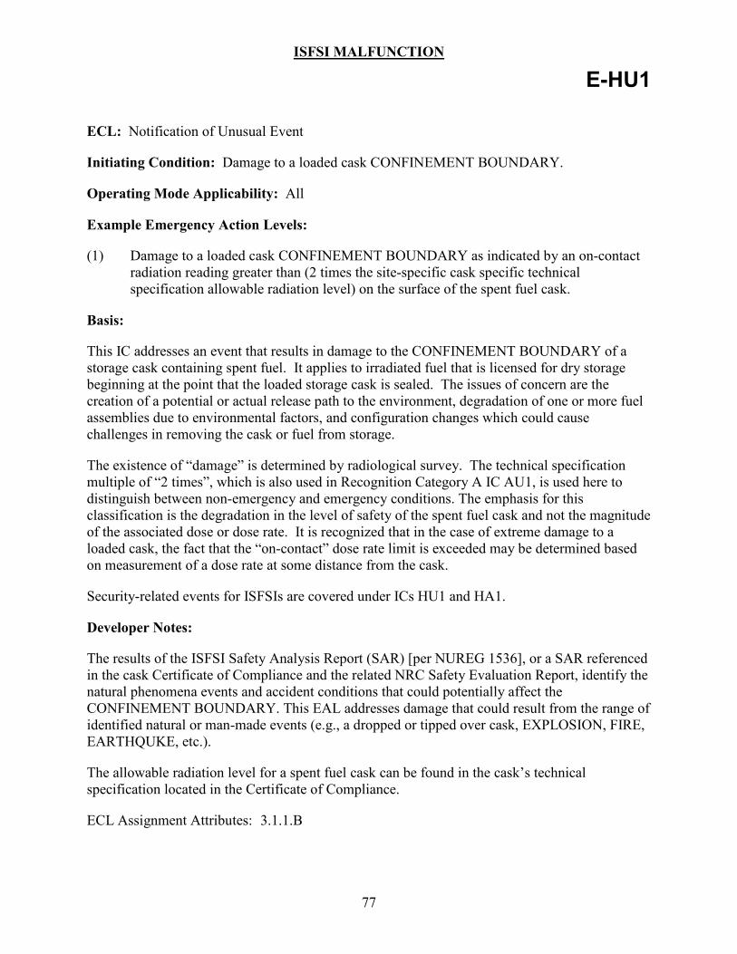
ISFSI MALFUNCTION
77
E-HU1
ECL: Notification of Unusual Event
Initiating Condition: Damage to a loaded cask CONFINEMENT BOUNDARY.
Operating Mode Applicability: All
Example Emergency Action Levels:
(1) Damage to a loaded cask CONFINEMENT BOUNDARY as indicated by an on-contact radiation reading greater than (2 times the site-specific cask specific technical specification allowable radiation level) on the surface of the spent fuel cask.
Basis:
This IC addresses an event that results in damage to the CONFINEMENT BOUNDARY of a storage cask containing spent fuel. It applies to irradiated fuel that is licensed for dry storage beginning at the point that the loaded storage cask is sealed. The issues of concern are the creation of a potential or actual release path to the environment, degradation of one or more fuel assemblies due to environmental factors, and configuration changes which could cause challenges in removing the cask or fuel from storage.
The existence of “damage” is determined by radiological survey. The technical specification multiple of “2 times”, which is also used in Recognition Category A IC AU1, is used here to distinguish between non-emergency and emergency conditions. The emphasis for this classification is the degradation in the level of safety of the spent fuel cask and not the magnitude of the associated dose or dose rate. It is recognized that in the case of extreme damage to a loaded cask, the fact that the “on-contact” dose rate limit is exceeded may be determined based on measurement of a dose rate at some distance from the cask.
Security-related events for ISFSIs are covered under ICs HU1 and HA1.
Developer Notes:
The results of the ISFSI Safety Analysis Report (SAR) [per NUREG 1536], or a SAR referenced in the cask Certificate of Compliance and the related NRC Safety Evaluation Report, identify the natural phenomena events and accident conditions that could potentially affect the CONFINEMENT BOUNDARY. This EAL addresses damage that could result from the range of identified natural or man-made events (e.g., a dropped or tipped over cask, EXPLOSION, FIRE, EARTHQUKE, etc.).
The allowable radiation level for a spent fuel cask can be found in the cask’s technical specification located in the Certificate of Compliance.
ECL Assignment Attributes: 3.1.1.B
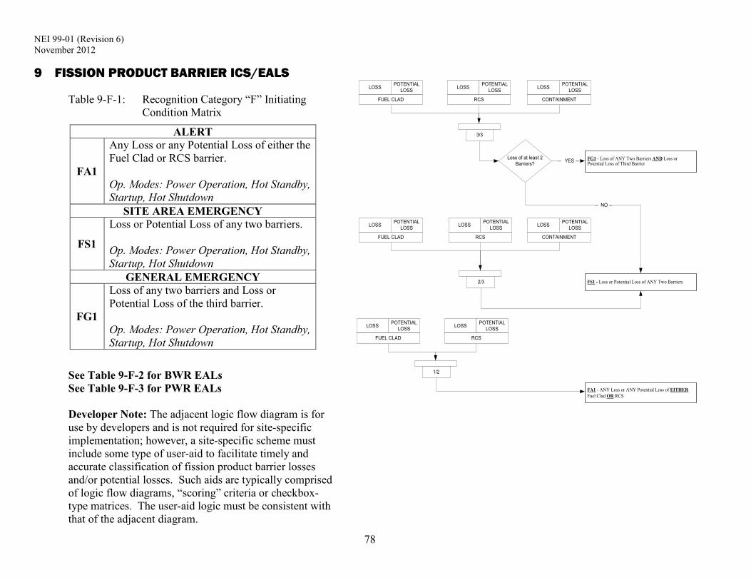
NEI 99-01 (Revision 6) November 2012
78
9 FISSION PRODUCT BARRIER ICS/EALS
Table 9-F-1: Recognition Category “F” Initiating Condition Matrix
ALERT
FA1
Any Loss or any Potential Loss of either the Fuel Clad or RCS barrier. Op. Modes: Power Operation, Hot Standby, Startup, Hot Shutdown
SITE AREA EMERGENCY
FS1
Loss or Potential Loss of any two barriers. Op. Modes: Power Operation, Hot Standby, Startup, Hot Shutdown
GENERAL EMERGENCY
FG1
Loss of any two barriers and Loss or Potential Loss of the third barrier. Op. Modes: Power Operation, Hot Standby, Startup, Hot Shutdown
See Table 9-F-2 for BWR EALs See Table 9-F-3 for PWR EALs Developer Note: The adjacent logic flow diagram is for use by developers and is not required for site-specific implementation; however, a site-specific scheme must include some type of user-aid to facilitate timely and accurate classification of fission product barrier losses and/or potential losses. Such aids are typically comprised of logic flow diagrams, “scoring” criteria or checkbox-type matrices. The user-aid logic must be consistent with that of the adjacent diagram.
3/3
2/3
1/2
Loss of at least 2 Barriers?
LOSS POTENTIAL LOSS
FUEL CLAD
LOSS POTENTIAL LOSS
RCS
LOSS POTENTIAL LOSS
CONTAINMENT
LOSS POTENTIAL LOSS
FUEL CLAD
LOSS POTENTIAL LOSS
RCS
LOSS POTENTIAL LOSS
CONTAINMENT
LOSS POTENTIAL LOSS
FUEL CLAD
LOSS POTENTIAL LOSS
RCS
FG1 - Loss of ANY Two Barriers AND Loss or Potential Loss of Third Barrier-- YES --
FS1 - Loss or Potential Loss of ANY Two Barriers
-- NO --
FA1 - ANY Loss or ANY Potential Loss of EITHER Fuel Clad OR RCS

NEI 99-01 (Revision 6) November 2012
79
Developer Notes
1. The logic used for these initiating conditions reflects the following considerations:
• The Fuel Clad Barrier and the RCS Barrier are weighted more heavily than the Containment Barrier.
• Unusual Event ICs associated with fission product barriers are addressed in Recognition Category S.
2. For accident conditions involving a radiological release, evaluation of the fission product barrier thresholds will need to be performed in conjunction with dose assessments to ensure correct and timely escalation of the emergency classification. For example, an evaluation of the fission product barrier thresholds may result in a Site Area Emergency classification while a dose assessment may indicate that an EAL for General Emergency IC AG1 has been exceeded.
3. The fission product barrier thresholds specified within a scheme are expected to reflect plant-specific design and operating characteristics. This may require that developers create different thresholds than those provided in the generic guidance.
4. Alternative presentation methods for the Recognition Category F ICs and fission product barrier thresholds are acceptable and include flow charts, block diagrams, and checklist-type tables. Developers must ensure that the site-specific method addresses all possible threshold combinations and classification outcomes shown in the BWR or PWR EAL fission product barrier tables. The NRC staff considers the presentation method of the Recognition Category F information to be an important user aid and may request a change to a particular proposed method if, among other reasons, the change is necessary to promote consistency across the industry.
5. As used in this Recognition Category, the term RCS leakage encompasses not just those types defined in Technical Specifications but also includes the loss of RCS mass to any location– inside containment, a secondary-side system (i.e., PWR steam generator tube leakage), an interfacing system, or outside of containment. The release of liquid or steam mass from the RCS due to the as-designed/expected operation of a relief valve is not considered to be RCS leakage.
6. At the Site Area Emergency level, classification decision-makers should maintain cognizance of how far present conditions are from meeting a threshold that would require a General Emergency declaration. For example, if the Fuel Clad and RCS fission product barriers were both lost, then there should be frequent assessments of containment radioactive inventory and integrity. Alternatively, if both the Fuel Clad and RCS fission product barriers were potentially lost, the Emergency Director would have more assurance that there was no immediate need to escalate to a General Emergency.
7. The ability to escalate to a higher emergency classification level in response to degrading conditions should be maintained. For example, a steady increase in RCS leakage would represent an increasing risk to public health and safety.

NEI 99-01 (Revision 6) November 2012
80
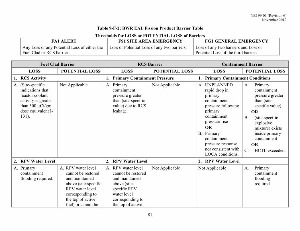
NEI 99-01 (Revision 6) November 2012
81
Table 9-F-2: BWR EAL Fission Product Barrier Table Thresholds for LOSS or POTENTIAL LOSS of Barriers
FA1 ALERT Any Loss or any Potential Loss of either the Fuel Clad or RCS barrier.
FS1 SITE AREA EMERGENCY Loss or Potential Loss of any two barriers.
FG1 GENERAL EMERGENCY Loss of any two barriers and Loss or Potential Loss of the third barrier.
Fuel Clad Barrier RCS Barrier Containment Barrier
LOSS POTENTIAL LOSS LOSS POTENTIAL LOSS LOSS POTENTIAL LOSS 1. RCS Activity 1. Primary Containment Pressure 1. Primary Containment Conditions A. (Site-specific
indications that reactor coolant activity is greater than 300 µCi/gm dose equivalent I-131).
Not Applicable A. Primary containment pressure greater than (site-specific value) due to RCS leakage.
Not Applicable A. UNPLANNED rapid drop in primary containment pressure following primary containment pressure rise OR
B. Primary containment pressure response not consistent with LOCA conditions.
A. Primary containment pressure greater than (site-specific value)
OR B. (site-specific
explosive mixture) exists inside primary containment
OR C. HCTL exceeded.
2. RPV Water Level 2. RPV Water Level 2. RPV Water Level A. Primary
containment flooding required.
A. RPV water level cannot be restored and maintained above (site-specific RPV water level corresponding to the top of active fuel) or cannot be
A. RPV water level cannot be restored and maintained above (site-specific RPV water level corresponding to the top of active
Not Applicable Not Applicable A. Primary containment flooding required.
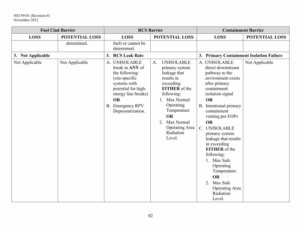
NEI 99-01 (Revision 6) November 2012
82
Fuel Clad Barrier RCS Barrier Containment Barrier LOSS POTENTIAL LOSS LOSS POTENTIAL LOSS LOSS POTENTIAL LOSS
determined. fuel) or cannot be determined.
3. Not Applicable 3. RCS Leak Rate 3. Primary Containment Isolation Failure Not Applicable Not Applicable A. UNISOLABLE
break in ANY of the following: (site-specific systems with potential for high-energy line breaks) OR
B. Emergency RPV Depressurization.
A. UNISOLABLE primary system leakage that results in exceeding EITHER of the following:
1. Max Normal Operating Temperature OR
2. Max Normal Operating Area Radiation Level.
A. UNISOLABLE direct downstream pathway to the environment exists after primary containment isolation signal OR
B. Intentional primary containment venting per EOPs OR
C. UNISOLABLE primary system leakage that results in exceeding EITHER of the following: 1. Max Safe
Operating Temperature. OR
2. Max Safe Operating Area Radiation Level.
Not Applicable

NEI 99-01 (Revision 6) November 2012
83
Fuel Clad Barrier RCS Barrier Containment Barrier LOSS POTENTIAL LOSS LOSS POTENTIAL LOSS LOSS POTENTIAL LOSS
4. Primary Containment Radiation 4. Primary Containment Radiation 4. Primary Containment Radiation A. Primary
containment radiation monitor reading greater than (site-specific value).
Not Applicable A. Primary containment radiation monitor reading greater than (site-specific value).
Not Applicable Not Applicable A. Primary containment radiation monitor reading greater than (site-specific value).
5. Other Indications 5. Other Indications 5. Other Indications A. (site-specific as
applicable) A. (site-specific as
applicable) A. (site-specific as
applicable) A. (site-specific as
applicable) A. (site-specific as
applicable) A. (site-specific as
applicable) 6. Emergency Director Judgment 6. Emergency Director Judgment 6. Emergency Director Judgment A. ANY condition in
the opinion of the Emergency Director that indicates Loss of the Fuel Clad Barrier.
A. ANY condition in the opinion of the Emergency Director that indicates Potential Loss of the Fuel Clad Barrier.
A. ANY condition in the opinion of the Emergency Director that indicates Loss of the RCS Barrier.
A. ANY condition in the opinion of the Emergency Director that indicates Potential Loss of the RCS Barrier.
A. ANY condition in the opinion of the Emergency Director that indicates Loss of the Containment Barrier.
A. ANY condition in the opinion of the Emergency Director that indicates Potential Loss of the Containment Barrier.
NEI 99-01 (Revision 6) November 2012
84
Basis Information For BWR EAL Fission Product Barrier Table 9-F-2
BWR FUEL CLAD BARRIER THRESHOLDS:
The Fuel Clad barrier consists of the zircalloy or stainless steel fuel bundle tubes that contain the fuel pellets.
1. RCS Activity
Loss 1.A
This threshold indicates that RCS radioactivity concentration is greater than 300 µCi/gm dose equivalent I-131. Reactor coolant activity above this level is greater than that expected for iodine spikes and corresponds to an approximate range of 2% to 5% fuel clad damage. Since this condition indicates that a significant amount of fuel clad damage has occurred, it represents a loss of the Fuel Clad Barrier.
There is no Potential Loss threshold associated with RCS Activity.
Developer Notes:
Threshold values should be determined assuming RCS radioactivity concentration equals 300 µCi/gm dose equivalent I-131. Other site-specific units may be used (e.g., µCi/cc).
Depending upon site-specific capabilities, this threshold may have a sample analysis component and/or a radiation monitor reading component.
Add this paragraph (or similar wording) to the Basis if the threshold includes a sample analysis component, “It is recognized that sample collection and analysis of reactor coolant with highly elevated activity levels could require several hours to complete. Nonetheless, a sample-related threshold is included as a backup to other indications.”
2. RPV Water Level
Loss 2.A
The Loss threshold represents the EOP requirement for primary containment flooding. This is identified in the BWROG EPGs/SAGs when the phrase, “Primary Containment Flooding Is Required," appears. Since a site-specific RPV water level is not specified here, the Loss threshold phrase, “Primary containment flooding required,” also accommodates the EOP need to flood the primary containment when RPV water level cannot be determined and core damage due to inadequate core cooling is believed to be occurring.
Potential Loss 2.A
This water level corresponds to the top of the active fuel and is used in the EOPs to indicate a challenge to core cooling.

NEI 99-01 (Revision 6) November 2012
85
BWR FUEL CLAD BARRIER THRESHOLDS:
The RPV water level threshold is the same as RCS barrier Loss threshold 2.A. Thus, this threshold indicates a Potential Loss of the Fuel Clad barrier and a Loss of the RCS barrier that appropriately escalates the emergency classification level to a Site Area Emergency.
This threshold is considered to be exceeded when, as specified in the site-specific EOPs, RPV water cannot be restored and maintained above the specified level following depressurization of the RPV (either manually, automatically or by failure of the RCS barrier) or when procedural guidance or a lack of low pressure RPV injection sources preclude Emergency RPV depressurization. EOPs allow the operator a wide choice of RPV injection sources to consider when restoring RPV water level to within prescribed limits. EOPs also specify depressurization of the RPV in order to facilitate RPV water level control with low-pressure injection sources. In some events, elevated RPV pressure may prevent restoration of RPV water level until pressure drops below the shutoff heads of available injection sources. Therefore, this Fuel Clad barrier Potential Loss is met only after either: 1) the RPV has been depressurized, or required emergency RPV depressurization has been attempted, giving the operator an opportunity to assess the capability of low-pressure injection sources to restore RPV water level or 2) no low pressure RPV injection systems are available, precluding RPV depressurization in an attempt to minimize loss of RPV inventory.
The term “cannot be restored and maintained above” means the value of RPV water level is not able to be brought above the specified limit (top of active fuel). The determination requires an evaluation of system performance and availability in relation to the RPV water level value and trend. A threshold prescribing declaration when a threshold value cannot be restored and maintained above a specified limit does not require immediate action simply because the current value is below the top of active fuel, but does not permit extended operation below the limit; the threshold must be considered reached as soon as it is apparent that the top of active fuel cannot be attained.
In high-power ATWS/failure to scram events, EOPs may direct the operator to deliberately lower RPV water level to the top of active fuel in order to reduce reactor power. RPV water level is then controlled between the top of active fuel and the Minimum Steam Cooling RPV Water Level (MSCRWL). Although such action is a challenge to core cooling and the Fuel Clad barrier, the immediate need to reduce reactor power is the higher priority. For such events, ICs SA5 or SS5 will dictate the need for emergency classification.
Since the loss of ability to determine if adequate core cooling is being provided presents a significant challenge to the fuel clad barrier, a potential loss of the fuel clad barrier is specified.

NEI 99-01 (Revision 6) November 2012
86
BWR FUEL CLAD BARRIER THRESHOLDS:
Developer Notes:
Loss 2.A
The phrase, “Primary containment flooding required,” should be modified to agree with the site-specific EOP phrase indicating exit from all EOPs and entry to the SAGs (e.g., drywell flooding required, etc.).
Potential Loss 2.A
The decision that "RPV water level cannot be determined" is directed by guidance given in the RPV water level control sections of the EOPs.
3. Not Applicable (included for numbering consistency between barrier tables)
4. Primary Containment Radiation
Loss 4.A
The radiation monitor reading corresponds to an instantaneous release of all reactor coolant mass into the primary containment, assuming that reactor coolant activity equals 300 µCi/gm dose equivalent I-131. Reactor coolant activity above this level is greater than that expected for iodine spikes and corresponds to an approximate range of 2% to 5% fuel clad damage. Since this condition indicates that a significant amount of fuel clad damage has occurred, it represents a loss of the Fuel Clad Barrier.
The radiation monitor reading in this threshold is higher than that specified for RCS Barrier Loss threshold 4.A since it indicates a loss of both the Fuel Clad Barrier and the RCS Barrier. Note that a combination of the two monitor readings appropriately escalates the emergency classification level to a Site Area Emergency.
There is no Potential Loss threshold associated with Primary Containment Radiation.
Developer Notes:
The reading should be determined assuming the instantaneous release and dispersal of the reactor coolant noble gas and iodine inventory, with RCS radioactivity concentration equal to 300 µCi/gm dose equivalent I-131, into the primary containment atmosphere.
NEI 99-01 (Revision 6) November 2012
87
BWR FUEL CLAD BARRIER THRESHOLDS:
5. Other Indications
Loss and/or Potential Loss 5.A
This subcategory addresses other site-specific thresholds that may be included to indicate loss or potential loss of the Fuel Clad barrier based on plant-specific design characteristics not considered in the generic guidance.
Developer Notes:
Loss and/or Potential Loss 5.A
Developers should determine if other reliable indicators exist to evaluate the status of this fission product barrier (e.g., review accident analyses described in the site Final Safety Analysis Report, as updated). The goal is to identify any unique or site-specific indications that will promote timely and accurate assessment of barrier status.
Any added thresholds should represent approximately the same relative threat to the barrier as the other thresholds in this column. Basis information for the other thresholds may be used to gauge the relative barrier threat level.
6. Emergency Director Judgment
Loss 6.A
This threshold addresses any other factors that are to be used by the Emergency Director in determining whether the Fuel Clad Barrier is lost.
Potential Loss 6.A
This threshold addresses any other factors that may be used by the Emergency Director in determining whether the Fuel Clad Barrier is potentially lost. The Emergency Director should also consider whether or not to declare the barrier potentially lost in the event that barrier status cannot be monitored.
Developer Notes:
None
NEI 99-01 (Revision 6) November 2012
88
BWR RCS BARRIER THRESHOLDS:
The RCS Barrier is the reactor coolant system pressure boundary and includes the RPV and all reactor coolant system piping up to and including the isolation valves.
1. Primary Containment Pressure
Loss 1.A
The (site-specific value) primary containment pressure is the drywell high pressure setpoint which indicates a LOCA by automatically initiating the ECCS or equivalent makeup system.
There is no Potential Loss threshold associated with Primary Containment Pressure.
Developer Notes:
None
2. RPV Water Level
Loss 2.A
This water level corresponds to the top of active fuel and is used in the EOPs to indicate challenge to core cooling.
The RPV water level threshold is the same as Fuel Clad barrier Potential Loss threshold 2.A. Thus, this threshold indicates a Loss of the RCS barrier and Potential Loss of the Fuel Clad barrier and that appropriately escalates the emergency classification level to a Site Area Emergency.
This threshold is considered to be exceeded when, as specified in the site-specific EOPs, RPV water cannot be restored and maintained above the specified level following depressurization of the RPV (either manually, automatically or by failure of the RCS barrier) or when procedural guidance or a lack of low pressure RPV injection sources preclude Emergency RPV depressurization EOPs allow the operator a wide choice of RPV injection sources to consider when restoring RPV water level to within prescribed limits. EOPs also specify depressurization of the RPV in order to facilitate RPV water level control with low-pressure injection sources. In some events, elevated RPV pressure may prevent restoration of RPV water level until pressure drops below the shutoff heads of available injection sources. Therefore, this RCS barrier Loss is met only after either: 1) the RPV has been depressurized, or required emergency RPV depressurization has been attempted, giving the operator an opportunity to assess the capability of low-pressure injection sources to restore RPV water level or 2) no low pressure RPV injection systems are available, precluding RPV depressurization in an attempt to minimize loss of RPV inventory.

NEI 99-01 (Revision 6) November 2012
89
BWR RCS BARRIER THRESHOLDS:
The term, “cannot be restored and maintained above,” means the value of RPV water level is not able to be brought above the specified limit (top of active fuel). The determination requires an evaluation of system performance and availability in relation to the RPV water level value and trend. A threshold prescribing declaration when a threshold value cannot be restored and maintained above a specified limit does not require immediate action simply because the current value is below the top of active fuel, but does not permit extended operation beyond the limit; the threshold must be considered reached as soon as it is apparent that the top of active fuel cannot be attained.
In high-power ATWS/failure to scram events, EOPs may direct the operator to deliberately lower RPV water level to the top of active fuel in order to reduce reactor power. RPV water level is then controlled between the top of active fuel and the Minimum Steam Cooling RPV Water Level (MSCRWL). Although such action is a challenge to core cooling and the Fuel Clad barrier, the immediate need to reduce reactor power is the higher priority. For such events, ICs SA5 or SS5 will dictate the need for emergency classification.
There is no RCS Potential Loss threshold associated with RPV Water Level.
3. RCS Leak Rate
Loss Threshold 3.A
Large high-energy lines that rupture outside primary containment can discharge significant amounts of inventory and jeopardize the pressure-retaining capability of the RCS until they are isolated. If it is determined that the ruptured line cannot be promptly isolated from the Control Room, the RCS barrier Loss threshold is met.
Loss Threshold 3.B
Emergency RPV Depressurization in accordance with the EOPs is indicative of a loss of the RCS barrier. If Emergency RPV Depressurization is performed, the plant operators are directed to open safety relief valves (SRVs) and keep them open. Even though the RCS is being vented into the suppression pool, a Loss of the RCS barrier exists due to the diminished effectiveness of the RCS to retain fission products within its boundary.
Potential Loss Threshold 3.A
Potential loss of RCS based on primary system leakage outside the primary containment is determined from EOP temperature or radiation Max Normal Operating values in areas such as main steam line tunnel, RCIC, HPCI, etc., which indicate a direct path from the RCS to areas outside primary containment.
A Max Normal Operating value is the highest value of the identified parameter expected to occur during normal plant operating conditions with all directly associated support and control systems functioning properly.

NEI 99-01 (Revision 6) November 2012
90
BWR RCS BARRIER THRESHOLDS:
The indicators reaching the threshold barriers and confirmed to be caused by RCS leakage from a primary system warrant an Alert classification. A primary system is defined to be the pipes, valves, and other equipment which connect directly to the RPV such that a reduction in RPV pressure will effect a decrease in the steam or water being discharged through an unisolated break in the system.
An UNISOLABLE leak which is indicated by Max Normal Operating values escalates to a Site Area Emergency when combined with Containment Barrier Loss threshold 3.A (after a containment isolation) and a General Emergency when the Fuel Clad Barrier criteria is also exceeded.
Developer Notes:
Loss Threshold 3.A
The list of systems included in this threshold should be the high energy lines which, if ruptured and remain unisolated, can rapidly depressurize the RPV. These lines are typically isolated by actuation of the Leak Detection system.
Large high-energy line breaks such as Main Steam Line (MSL), High Pressure Coolant Injection (HPCI), Feedwater, Reactor Water Cleanup (RWCU), Isolation Condenser (IC) or Reactor Core Isolation Cooling (RCIC) that are UNISOLABLE represent a significant loss of the RCS barrier.
4. Primary Containment Radiation
Loss 4.A
The radiation monitor reading corresponds to an instantaneous release of all reactor coolant mass into the primary containment, assuming that reactor coolant activity equals Technical Specification allowable limits. This value is lower than that specified for Fuel Clad Barrier Loss threshold 4.A since it indicates a loss of the RCS Barrier only.
There is no Potential Loss threshold associated with Primary Containment Radiation.
Developer Notes:
The reading should be determined assuming the instantaneous release and dispersal of the reactor coolant noble gas and iodine inventory, with RCS activity at Technical Specification allowable limits, into the primary containment atmosphere. Using RCS activity at Technical Specification allowable limits aligns this threshold with IC SU3. Also, RCS activity at this level will typically result in primary containment radiation levels that can be more readily detected by primary containment radiation monitors, and more readily differentiated from those caused by piping or component “shine” sources. If desired, a plant may use a lesser value of RCS activity for determining this value.

NEI 99-01 (Revision 6) November 2012
91
BWR RCS BARRIER THRESHOLDS:
In some cases, the site-specific physical location and sensitivity of the primary containment radiation monitor(s) may be such that radiation from a cloud of released RCS gases cannot be distinguished from radiation emanating from piping and components containing elevated reactor coolant activity. If so, refer to the Developer Guidance for Loss/Potential Loss 5.A and determine if an alternate indication is available.
5. Other Indications
Loss and/or Potential Loss 5.A
This subcategory addresses other site-specific thresholds that may be included to indicate loss or potential loss of the RCS barrier based on plant-specific design characteristics not considered in the generic guidance.
Developer Notes:
Loss and/or Potential Loss 5.A
Developers should determine if other reliable indicators exist to evaluate the status of this fission product barrier (e.g., review accident analyses described in the site Final Safety Analysis Report, as updated). The goal is to identify any unique or site-specific indications that will promote timely and accurate assessment of barrier status.
Any added thresholds should represent approximately the same relative threat to the barrier as the other thresholds in this column. Basis information for the other thresholds may be used to gauge the relative barrier threat level.
6. Emergency Director Judgment
Loss 6.A
This threshold addresses any other factors that are to be used by the Emergency Director in determining whether the RCS barrier is lost.
Potential Loss 6.A
This threshold addresses any other factors that may be used by the Emergency Director in determining whether the RCS Barrier is potentially lost. The Emergency Director should also consider whether or not to declare the barrier potentially lost in the event that barrier status cannot be monitored.
Developer Notes:
None

NEI 99-01 (Revision 6) November 2012
92
BWR CONTAINMENT BARRIER THRESHOLDS:
The Primary Containment Barrier includes the drywell, the wetwell, their respective interconnecting paths, and other connections up to and including the outermost containment isolation valves. Containment Barrier thresholds are used as criteria for escalation of the ECL from Alert to a Site Area Emergency or a General Emergency.
1. Primary Containment Conditions
Loss 1.A and 1.B
Rapid UNPLANNED loss of primary containment pressure (i.e., not attributable to drywell spray or condensation effects) following an initial pressure increase indicates a loss of primary containment integrity. Primary containment pressure should increase as a result of mass and energy release into the primary containment from a LOCA. Thus, primary containment pressure not increasing under these conditions indicates a loss of primary containment integrity.
These thresholds rely on operator recognition of an unexpected response for the condition and therefore a specific value is not assigned. The unexpected (UNPLANNED) response is important because it is the indicator for a containment bypass condition.
Potential Loss 1.A
The threshold pressure is the primary containment internal design pressure. Structural acceptance testing demonstrates the capability of the primary containment to resist pressures greater than the internal design pressure. A pressure of this magnitude is greater than those expected to result from any design basis accident and, thus, represent a Potential Loss of the Containment barrier.
Potential Loss 1.B
If hydrogen concentration reaches or exceeds the lower flammability limit, as defined in plant EOPs, in an oxygen rich environment, a potentially explosive mixture exists. If the combustible mixture ignites inside the primary containment, loss of the Containment barrier could occur.
Potential Loss 1.C
The Heat Capacity Temperature Limit (HCTL) is the highest suppression pool temperature from which Emergency RPV Depressurization will not raise:
Suppression chamber temperature above the maximum temperature capability of the suppression chamber and equipment within the suppression chamber which may be required to operate when the RPV is pressurized,
OR

NEI 99-01 (Revision 6) November 2012
93
BWR CONTAINMENT BARRIER THRESHOLDS: Suppression chamber pressure above Primary Containment Pressure Limit A, while
the rate of energy transfer from the RPV to the containment is greater than the capacity of the containment vent.
The HCTL is a function of RPV pressure, suppression pool temperature and suppression pool water level. It is utilized to preclude failure of the containment and equipment in the containment necessary for the safe shutdown of the plant and therefore, the inability to maintain plant parameters below the limit constitutes a potential loss of containment.
Developer Notes:
Potential Loss 1.B
BWR EPGs/SAGs specifically define the limits associated with explosive mixtures in terms of deflagration concentrations of hydrogen and oxygen. For Mk I/II containments the deflagration limits are “6% hydrogen and 5% oxygen in the drywell or suppression chamber”. For Mk III containments, the limit is the “Hydrogen Deflagration Overpressure Limit”. The threshold term “explosive mixture” is synonymous with the EPG/SAG “deflagration limits”.
Potential Loss 1.C
Since the HCTL is defined assuming a range of suppression pool water levels as low as the elevation of the downcomer openings in Mk I/II containments, or 2 feet above the elevation of the horizontal vents in a Mk III containment, it is unnecessary to consider separate Containment barrier Loss or Potential Loss thresholds for abnormal suppression pool water level conditions. If desired, developers may include a separate Containment Potential Loss threshold based on the inability to maintain suppression pool water level above the downcomer openings in Mk I/II containments, or 2 feet above the elevation of the horizontal vents in a Mk III containment with RPV pressure above the minimum decay heat removal pressure, if it will simplify the assessment of the suppression pool level component of the HCTL.
2. RPV Water Level
There is no Loss threshold associated with RPV Water Level.
Potential Loss 2.A
The Potential Loss threshold is identical to the Fuel Clad Loss RPV Water Level threshold 2.A. The Potential Loss requirement for Primary Containment Flooding indicates adequate core cooling cannot be restored and maintained and that core damage is possible. BWR EPGs/SAGs specify the conditions that require primary containment flooding. When primary containment flooding is required, the EPGs are exited and SAGs are entered. Entry into SAGs is a logical escalation in response to the inability to restore and maintain adequate core cooling.

NEI 99-01 (Revision 6) November 2012
94
BWR CONTAINMENT BARRIER THRESHOLDS:
PRA studies indicate that the condition of this Potential Loss threshold could be a core melt sequence which, if not corrected, could lead to RPV failure and increased potential for primary containment failure. In conjunction with the RPV water level Loss thresholds in the Fuel Clad and RCS barrier columns, this threshold results in the declaration of a General Emergency.
Developer Notes:
The phrase, “Primary containment flooding required,” should be modified to agree with the site-specific EOP phrase indicating exit from all EOPs and entry to the SAGs (e.g., drywell flooding required, etc.).
3. Primary Containment Isolation Failure
These thresholds address incomplete containment isolation that allows an UNISOLABLE direct release to the environment.
Loss 3.A
The use of the modifier “direct” in defining the release path discriminates against release paths through interfacing liquid systems or minor release pathways, such as instrument lines, not protected by the Primary Containment Isolation System (PCIS).
The existence of a filter is not considered in the threshold assessment. Filters do not remove fission product noble gases. In addition, a filter could become ineffective due to iodine and/or particulate loading beyond design limits (i.e., retention ability has been exceeded) or water saturation from steam/high humidity in the release stream.
Following the leakage of RCS mass into primary containment and a rise in primary containment pressure, there may be minor radiological releases associated with allowable primary containment leakage through various penetrations or system components. Minor releases may also occur if a primary containment isolation valve(s) fails to close but the primary containment atmosphere escapes to an enclosed system. These releases do not constitute a loss or potential loss of primary containment but should be evaluated using the Recognition Category A ICs.
Loss 3.B
EOPs may direct primary containment isolation valve logic(s) to be intentionally bypassed, even if offsite radioactivity release rate limits will be exceeded. Under these conditions with a valid primary containment isolation signal, the containment should also be considered lost if primary containment venting is actually performed.
Intentional venting of primary containment for primary containment pressure or combustible gas control to the secondary containment and/or the environment is a Loss of the Containment. Venting for primary containment pressure control when not in an accident situation (e.g., to control pressure below the drywell high pressure scram setpoint) does not meet the threshold condition.

NEI 99-01 (Revision 6) November 2012
95
Loss 3.C
The Max Safe Operating Temperature and the Max Safe Operating Radiation Level are each the highest value of these parameters at which neither: (1) equipment necessary for the safe shutdown of the plant will fail, nor (2) personnel access necessary for the safe shutdown of the plant will be precluded. EOPs utilize these temperatures and radiation levels to establish conditions under which RPV depressurization is required.
BWR CONTAINMENT BARRIER THRESHOLDS:
The temperatures and radiation levels should be confirmed to be caused by RCS leakage from a primary system. A primary system is defined to be the pipes, valves, and other equipment which connect directly to the RPV such that a reduction in RPV pressure will effect a decrease in the steam or water being discharged through an unisolated break in the system.
In combination with RCS potential loss 3.A this threshold would result in a Site Area Emergency.
There is no Potential Loss threshold associated with Primary Containment Isolation Failure.
Developer Notes:
Loss 3.B
Consideration may be given to specifying the specific procedural step within the Primary Containment Control EOP that defines intentional venting of the Primary Containment regardless of offsite radioactivity release rate.
4. Primary Containment Radiation
There is no Loss threshold associated with Primary Containment Radiation.
Potential Loss 4.A
The radiation monitor reading corresponds to an instantaneous release of all reactor coolant mass into the primary containment, assuming that 20% of the fuel cladding has failed. This level of fuel clad failure is well above that used to determine the analogous Fuel Clad Barrier Loss and RCS Barrier Loss thresholds.
NUREG-1228, Source Estimations During Incident Response to Severe Nuclear Power Plant Accidents, indicates the fuel clad failure must be greater than approximately 20% in order for there to be a major release of radioactivity requiring offsite protective actions. For this condition to exist, there must already have been a loss of the RCS Barrier and the Fuel Clad Barrier. It is therefore prudent to treat this condition as a potential loss of containment which would then escalate the emergency classification level to a General Emergency.

NEI 99-01 (Revision 6) November 2012
96
Developer Notes:
NUREG-1228, Source Estimations During Incident Response to Severe Nuclear Power Plant Accidents, provides the basis for using the 20% fuel cladding failure value. Unless there is a site-specific analysis justifying a different value, the reading should be determined assuming the instantaneous release and dispersal of the reactor coolant noble gas and iodine inventory associated with 20% fuel clad failure into the primary containment atmosphere.
BWR CONTAINMENT BARRIER THRESHOLDS:
5. Other Indications
Loss and/or Potential Loss 5.A
This subcategory addresses other site-specific thresholds that may be included to indicate loss or potential loss of the Containment barrier based on plant-specific design characteristics not considered in the generic guidance.
Developer Notes:
Loss and/or Potential Loss 5.A
Developers should determine if other reliable indicators exist to evaluate the status of this fission product barrier (e.g., review accident analyses described in the site Final Safety Analysis Report, as updated). The goal is to identify any unique or site-specific indications that will promote timely and accurate assessment of barrier status.
Any added thresholds should represent approximately the same relative threat to the barrier as the other thresholds in this column. Basis information for the other thresholds may be used to gauge the relative barrier threat level.
6. Emergency Director Judgment
Loss 6.A
This threshold addresses any other factors that are to be used by the Emergency Director in determining whether the Containment barrier is lost.
Potential Loss 6.A
This threshold addresses any other factors that may be used by the Emergency Director in determining whether the Containment Barrier is potentially lost. The Emergency Director should also consider whether or not to declare the barrier potentially lost in the event that barrier status cannot be monitored.
Developer Notes:
None

NEI 99-01 (Revision 6) November 2012
97
Table 9-F-3: PWR EAL Fission Product Barrier Table Thresholds for LOSS or POTENTIAL LOSS of Barriers
FA1 ALERT Any Loss or any Potential Loss of either the Fuel Clad or RCS barrier.
FS1 SITE AREA EMERGENCY Loss or Potential Loss of any two barriers.
FG1 GENERAL EMERGENCY Loss of any two barriers and Loss or Potential Loss of the third barrier.
Fuel Clad Barrier RCS Barrier Containment Barrier
LOSS POTENTIAL LOSS LOSS POTENTIAL LOSS LOSS POTENTIAL LOSS 1. RCS or SG Tube Leakage 1. RCS or SG Tube Leakage 1. RCS or SG Tube Leakage Not Applicable
A. RCS/reactor vessel level less than (site-specific level).
A. An automatic or manual ECCS (SI) actuation is required by EITHER of the following: 1. UNISOLABLE
RCS leakage OR
2. SG tube RUPTURE.
A. Operation of a standby charging (makeup) pump is required by EITHER of the following: 1. UNISOLABLE
RCS leakage OR
2. SG tube leakage.
OR B. RCS cooldown
rate greater than (site-specific pressurized thermal shock criteria/limits defined by site-specific indications).
A. A leaking or RUPTURED SG is FAULTED outside of containment.
Not Applicable

NEI 99-01 (Revision 6) November 2012
98
Fuel Clad Barrier RCS Barrier Containment Barrier LOSS POTENTIAL LOSS LOSS POTENTIAL LOSS LOSS POTENTIAL LOSS
2. Inadequate Heat Removal 2. Inadequate Heat Removal 2. Inadequate Heat Removal A. Core exit
thermocouple readings greater than (site-specific temperature value).
A. Core exit thermocouple readings greater than (site-specific temperature value).
OR B. Inadequate RCS
heat removal capability via steam generators as indicated by (site-specific indications).
Not Applicable
A. Inadequate RCS heat removal capability via steam generators as indicated by (site-specific indications).
Not Applicable
A. 1. (Site-specific criteria for entry into core cooling restoration procedure)
AND 2. Restoration
procedure not effective within 15 minutes.
3. RCS Activity / Containment Radiation 3. RCS Activity / Containment Radiation 3. RCS Activity / Containment Radiation A. Containment
radiation monitor reading greater than (site-specific value).
OR B. (Site-specific
indications that reactor coolant activity is greater than 300 µCi/gm dose equivalent I-131).
Not Applicable A. Containment radiation monitor reading greater than (site-specific value).
Not Applicable Not Applicable
A. Containment radiation monitor reading greater than (site-specific value).

NEI 99-01 (Revision 6) November 2012
99
Fuel Clad Barrier RCS Barrier Containment Barrier LOSS POTENTIAL LOSS LOSS POTENTIAL LOSS LOSS POTENTIAL LOSS
4. Containment Integrity or Bypass 4. Containment Integrity or Bypass 4. Containment Integrity or Bypass Not Applicable Not Applicable Not Applicable Not Applicable A. Containment
isolation is required
AND EITHER of the following: 1. Containment
integrity has been lost based on Emergency Director judgment.
OR 2. UNISOLABLE
pathway from the containment to the environment exists.
OR B. Indications of RCS
leakage outside of containment.
A. Containment pressure greater than (site-specific value) OR
B. Explosive mixture exists inside containment OR
C. 1. Containment pressure greater than (site-specific pressure setpoint) AND
2. Less than one full train of (site-specific system or equipment) is operating per design for 15 minutes or longer.
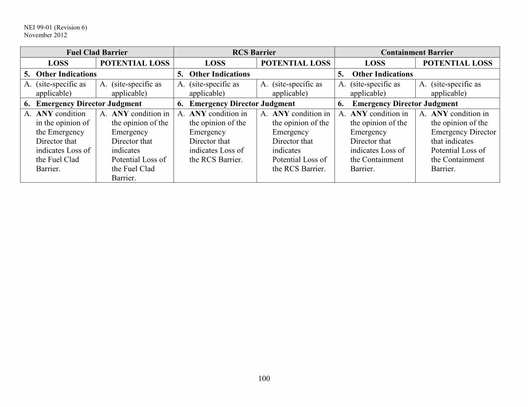
NEI 99-01 (Revision 6) November 2012
100
Fuel Clad Barrier RCS Barrier Containment Barrier LOSS POTENTIAL LOSS LOSS POTENTIAL LOSS LOSS POTENTIAL LOSS
5. Other Indications 5. Other Indications 5. Other Indications A. (site-specific as
applicable) A. (site-specific as
applicable) A. (site-specific as
applicable) A. (site-specific as
applicable) A. (site-specific as
applicable) A. (site-specific as
applicable) 6. Emergency Director Judgment 6. Emergency Director Judgment 6. Emergency Director Judgment A. ANY condition
in the opinion of the Emergency Director that indicates Loss of the Fuel Clad Barrier.
A. ANY condition in the opinion of the Emergency Director that indicates Potential Loss of the Fuel Clad Barrier.
A. ANY condition in the opinion of the Emergency Director that indicates Loss of the RCS Barrier.
A. ANY condition in the opinion of the Emergency Director that indicates Potential Loss of the RCS Barrier.
A. ANY condition in the opinion of the Emergency Director that indicates Loss of the Containment Barrier.
A. ANY condition in the opinion of the Emergency Director that indicates Potential Loss of the Containment Barrier.

NEI 99-01 (Revision 6) November 2012
101
Basis Information For PWR EAL Fission Product Barrier Table 9-F-3
Developer Notes:
Threshold Parameters and Values
Each PWR owner’s group has developed a methodology for guiding the development and implementation of EOPs (i.e., assessing plant parameters, and determining and prioritizing operator actions). Many of the thresholds contained in the PWR EAL Fission Product Barrier Table reflect conditions that are specifically addressed in EOPs (e.g., a loss of heat removal capability by the steam generators). When developing a site-specific threshold, developers should use the parameters and values specified within their EOPs that align with the condition described by the generic threshold and basis, and related developer notes. This approach will ensure consistency between the site-specific EOPs and emergency classification scheme, and thus facilitate more timely and accurate classification assessments.
In support of EOP development and implementation, the Westinghouse Owners Group (WOG) developed a defined set of Critical Safety Functions as part of their Emergency Response Guidelines. The WOG approach structures EOPs to maintain and/or restore these Critical Safety Functions, and to do so in a prioritized and systematic manner. The WOG Critical Safety Functions are presented below.
Subcriticality Core Cooling Heat Sink RCS Integrity Containment RCS Inventory
The WOG ERGs provide a methodology for monitoring the status of the Critical Safety Functions and classifying the significance of a challenge to a function; this methodology is referred to as the Critical Safety Function Status Trees (CSFSTs). For plants that have implemented the WOG ERGs, the guidance in NEI 99-01 allows for use of certain CSFST assessment results as EALs and fission product barrier loss/potential loss thresholds. In this manner, an emergency classification assessment may flow directly from a CSFST assessment.
It is important to understand that the CSFSTs are evaluated using plant parameters, and that they are simply a vendor-specific method for collectively evaluating a set of parameters for purposes of driving emergency operating procedure usage. For the emergency conditions of interest, the generic thresholds within the PWR EAL Fission Product Barrier Table specify the plant parameters that define a potential loss or loss of a fission product barrier; however, as described in the associated Developer Notes, a CSFST terminus may be used as well. For this reason, inclusion of the CSFST-related thresholds would be redundant to the parameter-based thresholds for plants that employ the WOG ERGs.
Sites that employ the WOG ERGs may, at their discretion, include the CSFST-based loss and potential loss thresholds as described in the Developer Notes. Developers at these sites should consult with their classification decision-makers to determine if inclusion would assist with

NEI 99-01 (Revision 6) November 2012
102
timely and accurate emergency classification. This decision should consider the effects of any site-specific changes to the generic WOG CSFST evaluation logic and setpoints, as well as those arising from user rules applicable to emergency operating procedures (e.g., exceptions to procedure entry or transition due to specific accident conditions or loss of a support system).
The CSFST thresholds may be addressed in one of 3 ways:
1) Not incorporated; thresholds will use parameters and values as discussed in the Developer Notes.
2) Incorporated along with parameter and value thresholds (e.g., a fuel clad loss would have 2 thresholds such as “CETs > 1200oF” and “Core Cooling Red entry conditions met”.
3) Used in lieu of parameters and values for all thresholds.
With one exception, if a decision is made to include the CSFST-based thresholds, then all such allowed thresholds must be used in the table (e.g., it is not permissible to use only the C Orange terminus as a potential loss of the fuel clad barrier threshold and disregard all other CSFST-based thresholds). The one exception is the RCS Integrity (P) CSFST. Because of the complexity of the P Red decision-point that relies on an assessment a pressure-temperature curve, a P Red condition may be used as an RCS potential loss threshold without the need to incorporate the other CSFST-based thresholds.
NEI 99-01 (Revision 6) November 2012
103
PWR FUEL CLAD BARRIER THRESHOLDS:
The Fuel Clad Barrier consists of the cladding material that contains the fuel pellets.
1. RCS or SG Tube Leakage
There is no Loss threshold associated with RCS or SG Tube Leakage.
Potential Loss 1.A
This reading indicates a reduction in reactor vessel water level sufficient to allow the onset of heat-induced cladding damage.
Developer Notes:
Potential Loss 1.A
Enter the site-specific reactor vessel water level value(s) used by EOPs to identify a degraded core cooling condition (e.g., requires prompt restoration action). The reactor vessel level that corresponds to approximately the top of active fuel may also be used.
For plants that have implemented Westinghouse Owners Group Emergency Response Guidelines, enter the reactor vessel level(s) used for the Core Cooling Orange Path (including dependencies upon the status of RCPs, if applicable).
Westinghouse ERG Plants
Developers should consider including a threshold the same as, or similar to, “Core Cooling Orange entry conditions met” in accordance with the guidance at the front of this section.
2. Inadequate Heat Removal
Loss 2.A
This reading indicates temperatures within the core are sufficient to cause significant superheating of reactor coolant.
Potential Loss 2.A
This reading indicates temperatures within the core are sufficient to allow the onset of heat-induced cladding damage.
Potential Loss 2.B
This condition indicates an extreme challenge to the ability to remove RCS heat using the steam generators (i.e., loss of an effective secondary-side heat sink). This condition represents a potential loss of the Fuel Clad Barrier. In accordance with EOPs, there may be unusual accident conditions during which operators intentionally reduce the heat
NEI 99-01 (Revision 6) November 2012
104
removal capability of the steam generators; during these conditions, classification using threshold is not warranted.
PWR FUEL CLAD BARRIER THRESHOLDS:
Meeting this threshold results in a Site Area Emergency because this threshold is identical to RCS Barrier Potential Loss threshold 2.A; both will be met. This condition warrants a Site Area Emergency declaration because inadequate RCS heat removal may result in fuel heat-up sufficient to damage the cladding and increase RCS pressure to the point where mass will be lost from the system.
Developer Notes:
Some site-specific EOPs and/or EOP user guidelines may establish decision-making criteria concerning the number or other attributes of thermocouple readings necessary to drive actions (e.g., 5 CETs reading greater than 1,200oF is required before transitioning to an inadequate core cooling procedure). To maintain consistency with EOPs, these decision-making criteria may be used in the core exit thermocouple reading thresholds.
Loss 2.A
Enter a site-specific temperature value that corresponds to significant in-core superheating of reactor coolant. 1,200oF may also be used.
For plants that have implemented Westinghouse Owners Group Emergency Response Guidelines, enter the parameters and values used in the Core Cooling Red Path.
Potential Loss 2.A
Enter a site-specific temperature value that corresponds to core conditions at the onset of heat-induced cladding damage (e.g., the temperature allowing for the formation of superheated steam assuming that the RCS is intact). 700oF may also be used.
For plants that have implemented Westinghouse Owners Group Emergency Response Guidelines, enter the parameters and values used in the Core Cooling Orange Path.
Potential Loss 2.B
Enter the site-specific parameters and values that define an extreme challenge to the ability to remove heat from the RCS via the steam generators. These will typically be parameters and values that would require operators to take prompt action to address this condition.
For plants that have implemented Westinghouse Owners Group Emergency Response Guidelines, enter the parameters and values used in the Heat Sink Red Path.
NEI 99-01 (Revision 6) November 2012
105
Westinghouse ERG Plants
As a loss indication, developers should consider including a threshold the same as, or similar to, “Core Cooling Red entry conditions met” in accordance with the guidance at the front of this section.
PWR FUEL CLAD BARRIER THRESHOLDS:
As a potential loss indication, developers should consider including a threshold the same as, or similar to, “Core Cooling Orange entry conditions met” in accordance with the guidance at the front of this section.
As a potential loss indication, developers should consider including a threshold the same as, or similar to, “Heat Sink Red entry conditions met” in accordance with the guidance at the front of this section.
3. RCS Activity / Containment Radiation
Loss 3.A
The radiation monitor reading corresponds to an instantaneous release of all reactor coolant mass into the containment, assuming that reactor coolant activity equals 300µCi/gm dose equivalent I-131. Reactor coolant activity above this level is greater than that expected for iodine spikes and corresponds to an approximate range of 2% to 5% fuel clad damage. Since this condition indicates that a significant amount of fuel clad damage has occurred, it represents a loss of the Fuel Clad Barrier.
The radiation monitor reading in this threshold is higher than that specified for RCS Barrier Loss threshold 3.A since it indicates a loss of both the Fuel Clad Barrier and the RCS Barrier. Note that a combination of the two monitor readings appropriately escalates the emergency classification level to a Site Area Emergency.
Loss 3.B
This threshold indicates that RCS radioactivity concentration is greater than 300 µCi/gm dose equivalent I-131. Reactor coolant activity above this level is greater than that expected for iodine spikes and corresponds to an approximate range of 2% to 5% fuel clad damage. Since this condition indicates that a significant amount of fuel clad damage has occurred, it represents a loss of the Fuel Clad Barrier.
There is no Potential Loss threshold associated with RCS Activity / Containment Radiation.
Developer Notes:
Loss 3.A

NEI 99-01 (Revision 6) November 2012
106
The reading should be determined assuming the instantaneous release and dispersal of the reactor coolant noble gas and iodine inventory, with RCS radioactivity concentration equal to 300 µCi/gm dose equivalent I-131, into the containment atmosphere.
PWR FUEL CLAD BARRIER THRESHOLDS:
Loss 3.B
Threshold values should be determined assuming RCS radioactivity concentration equals 300 µCi/gm dose equivalent I-131. Other site-specific units may be used (e.g., µCi/cc).
Depending upon site-specific capabilities, this threshold may have a sample analysis component and/or a radiation monitor reading component.
Add this paragraph (or similar wording) to the Basis if the threshold includes a sample analysis component, “It is recognized that sample collection and analysis of reactor coolant with highly elevated activity levels could require several hours to complete. Nonetheless, a sample-related threshold is included as a backup to other indications.”
4. Containment Integrity or Bypass
Not Applicable (included for numbering consistency)
5. Other Indications
Loss and/or Potential Loss 5.A
This subcategory addresses other site-specific thresholds that may be included to indicate loss or potential loss of the Fuel Clad barrier based on plant-specific design characteristics not considered in the generic guidance.
Developer Notes:
Loss and/or Potential Loss 5.A
Developers should determine if other reliable indicators exist to evaluate the status of this fission product barrier (e.g., review accident analyses described in the site Final Safety Analysis Report, as updated). The goal is to identify any unique or site-specific indications that will promote timely and accurate assessment of barrier status.
Any added thresholds should represent approximately the same relative threat to the barrier as the other thresholds in this column. Basis information for the other thresholds may be used to gauge the relative barrier threat level.

NEI 99-01 (Revision 6) November 2012
107
6. Emergency Director Judgment
Loss 6.A
This threshold addresses any other factors that may be used by the Emergency Director in determining whether the Fuel Clad Barrier is lost.
PWR FUEL CLAD BARRIER THRESHOLDS:
Potential Loss 6.A
This threshold addresses any other factors that may be used by the Emergency Director in determining whether the Fuel Clad Barrier is potentially lost. The Emergency Director should also consider whether or not to declare the barrier potentially lost in the event that barrier status cannot be monitored.
Developer Notes:
None

NEI 99-01 (Revision 6) November 2012
108
PWR RCS BARRIER THRESHOLDS:
The RCS Barrier includes the RCS primary side and its connections up to and including the pressurizer safety and relief valves, and other connections up to and including the primary isolation valves.
1. RCS or SG Tube Leakage
Loss 1.A
This threshold is based on an UNISOLABLE RCS leak of sufficient size to require an automatic or manual actuation of the Emergency Core Cooling System (ECCS). This condition clearly represents a loss of the RCS Barrier.
This threshold is applicable to unidentified and pressure boundary leakage, as well as identified leakage. It is also applicable to UNISOLABLE RCS leakage through an interfacing system. The mass loss may be into any location – inside containment, to the secondary-side (i.e., steam generator tube leakage) or outside of containment.
A steam generator with primary-to-secondary leakage of sufficient magnitude to require a safety injection is considered to be RUPTURED. If a RUPTURED steam generator is also FAULTED outside of containment, the declaration escalates to a Site Area Emergency since the Containment Barrier Loss threshold 1.A will also be met.
Potential Loss 1.A
This threshold is based on an UNISOLABLE RCS leak that results in the inability to maintain pressurizer level within specified limits by operation of a normally used charging (makeup) pump, but an ECCS (SI) actuation has not occurred. The threshold is met when an operating procedure, or operating crew supervision, directs that a standby charging (makeup) pump be placed in service to restore and maintain pressurizer level.
This threshold is applicable to unidentified and pressure boundary leakage, as well as identified leakage. It is also applicable to UNISOLABLE RCS leakage through an interfacing system. The mass loss may be into any location – inside containment, to the secondary-side (i.e., steam generator tube leakage) or outside of containment.
If a leaking steam generator is also FAULTED outside of containment, the declaration escalates to a Site Area Emergency since the Containment Barrier Loss threshold 1.A will also be met.
Potential Loss 1.B
This condition indicates an extreme challenge to the integrity of the RCS pressure boundary due to pressurized thermal shock – a transient that causes rapid RCS cooldown while the RCS is in Mode 3 or higher (i.e., hot and pressurized).
NEI 99-01 (Revision 6) November 2012
109
PWR RCS BARRIER THRESHOLDS:
Developer Notes:
Loss 1.A
Actuation of the ECCS may also be referred to as Safety Injection (SI) actuation or other appropriate site-specific term.
Potential Loss 1.A
Depending upon charging pump flow capacities and RCS volume control parameters, developers may use an RCS leak rate value of 50 gpm, or an appropriate site-specific value, as an alternate Potential Loss threshold. If used, the threshold wording should reflect that the determination of the leak rate value excludes normal reductions in RCS inventory (e.g., by the letdown system or RCP seal leakoff).
Potential Loss 1.B
Enter the site-specific indications that define an extreme challenge to the integrity of the RCS pressure boundary due to pressurized thermal shock – a transient that causes rapid RCS cooldown while the RCS is in Mode 3 or higher (i.e., hot and pressurized). These will typically be parameters and values that would require operators to take prompt action to address a pressurized thermal shock condition. Developers should also determine if the threshold needs to reflect any dependencies used as EOP transition/entry decision points or condition validation criteria (e.g., an EOP used to respond to an excessive RCS cooldown may not be entered or immediately exited if RCS pressure is below a certain value).
For plants that have implemented Westinghouse Owners Group Emergency Response Guidelines, enter the parameters and values used in the RCS Integrity Red Path. Because of the complexity of certain decision-points within the Red Path of this CSFST, developers at these plants may elect to not include the specific parameters and values, and instead follow the guidance below.
Westinghouse ERG Plants
As a potential loss indication, developers should consider including a threshold the same as, or similar to, “RCS Integrity Red entry conditions met” in accordance with the guidance at the front of this section. As noted above, developers should ensure that the threshold wording reflects any EOP transition/entry decision points or condition validation criteria. For example, a threshold might read “RCS Integrity (P) Red entry conditions met with RCS pressure > 300 psig.”
2. Inadequate Heat Removal
There is no Loss threshold associated with Inadequate Heat Removal.

NEI 99-01 (Revision 6) November 2012
110
PWR RCS BARRIER THRESHOLDS:
Potential Loss 2.A
This condition indicates an extreme challenge to the ability to remove RCS heat using the steam generators (i.e., loss of an effective secondary-side heat sink). This condition represents a potential loss of the RCS Barrier. In accordance with EOPs, there may be unusual accident conditions during which operators intentionally reduce the heat removal capability of the steam generators; during these conditions, classification using threshold is not warranted.
Meeting this threshold results in a Site Area Emergency because this threshold is identical to Fuel Clad Barrier Potential Loss threshold 2.B; both will be met. This condition warrants a Site Area Emergency declaration because inadequate RCS heat removal may result in fuel heat-up sufficient to damage the cladding and increase RCS pressure to the point where mass will be lost from the system.
Developer Notes:
Potential Loss 2.A
Enter the site-specific parameters and values that define an extreme challenge to the ability to remove heat from the RCS via the steam generators. These will typically be parameters and values that would require operators to take prompt action to address this condition.
For plants that have implemented Westinghouse Owners Group Emergency Response Guidelines, enter the parameters and values used in the Heat Sink Red Path.
Westinghouse ERG Plants
Developers should consider including a threshold the same as, or similar to, “Heat Sink Red entry conditions met” in accordance with the guidance at the front of this section.
3. RCS Activity / Containment Radiation
Loss 3.A
The radiation monitor reading corresponds to an instantaneous release of all reactor coolant mass into the containment, assuming that reactor coolant activity equals Technical Specification allowable limits. This value is lower than that specified for Fuel Clad Barrier Loss threshold 3.A since it indicates a loss of the RCS Barrier only.
There is no Potential Loss threshold associated with RCS Activity / Containment Radiation.
NEI 99-01 (Revision 6) November 2012
111
PWR RCS BARRIER THRESHOLDS:
Developer Notes:
Loss 3.A
The reading should be determined assuming the instantaneous release and dispersal of the reactor coolant noble gas and iodine inventory, with RCS activity at Technical Specification allowable limits, into the containment atmosphere. Using RCS activity at
Technical Specification allowable limits aligns this threshold with IC SU3. Also, RCS activity at this level will typically result in containment radiation levels that can be more readily detected by containment radiation monitors, and more readily differentiated from those caused by piping or component “shine” sources. If desired, a plant may use a lesser value of RCS activity for determining this value.
In some cases, the site-specific physical location and sensitivity of the containment radiation monitor(s) may be such that radiation from a cloud of released RCS gases cannot be distinguished from radiation emanating from piping and components containing elevated reactor coolant activity. If so, refer to the Developer Notes for Loss/Potential Loss 5.A and determine if an alternate indication is available.
4. Containment Integrity or Bypass
Not Applicable (included for numbering consistency)
5. Other Indications
Loss and/or Potential Loss 5.A
This subcategory addresses other site-specific thresholds that may be included to indicate loss or potential loss of the RCS barrier based on plant-specific design characteristics not considered in the generic guidance.
Developer Notes:
Loss and/or Potential Loss 5.A
Developers should determine if other reliable indicators exist to evaluate the status of this fission product barrier (e.g., review accident analyses described in the site Final Safety Analysis Report, as updated). The goal is to identify any unique or site-specific indications that will promote timely and accurate assessment of barrier status.
Any added thresholds should represent approximately the same relative threat to the barrier as the other thresholds in this column. Basis information for the other thresholds may be used to gauge the relative barrier threat level.

NEI 99-01 (Revision 6) November 2012
112
PWR RCS BARRIER THRESHOLDS:
6. Emergency Director Judgment
Loss 6.A
This threshold addresses any other factors that may be used by the Emergency Director in determining whether the RCS Barrier is lost.
Potential Loss 6.A
This threshold addresses any other factors that may be used by the Emergency Director in determining whether the RCS Barrier is potentially lost. The Emergency Director should also consider whether or not to declare the barrier potentially lost in the event that barrier status cannot be monitored.
Developer Notes:
None

NEI 99-01 (Revision 6) November 2012
113
PWR CONTAINMENT BARRIER THRESHOLDS:
The Containment Barrier includes the containment building and connections up to and including the outermost containment isolation valves. This barrier also includes the main steam, feedwater, and blowdown line extensions outside the containment building up to and including the outermost secondary side isolation valve. Containment Barrier thresholds are used as criteria for escalation of the ECL from Alert to a Site Area Emergency or a General Emergency.
1. RCS or SG Tube Leakage
Loss 1.A
This threshold addresses a leaking or RUPTURED Steam Generator (SG) that is also FAULTED outside of containment. The condition of the SG, whether leaking or RUPTURED, is determined in accordance with the thresholds for RCS Barrier Potential Loss 1.A and Loss 1.A, respectively. This condition represents a bypass of the containment barrier.
FAULTED is a defined term within the NEI 99-01 methodology; this determination is not necessarily dependent upon entry into, or diagnostic steps within, an EOP. For example, if the pressure in a steam generator is decreasing uncontrollably [part of the FAULTED definition] and the faulted steam generator isolation procedure is not entered because EOP user rules are dictating implementation of another procedure to address a higher priority condition, the steam generator is still considered FAULTED for emergency classification purposes. The FAULTED criterion establishes an appropriate lower bound on the size of a steam release that may require an emergency classification. Steam releases of this size are readily observable with normal Control Room indications. The lower bound for this aspect of the containment barrier is analogous to the lower bound criteria specified in IC SU3 for the fuel clad barrier (i.e., RCS activity values) and IC SU4 for the RCS barrier (i.e., RCS leak rate values). This threshold also applies to prolonged steam releases necessitated by operational considerations such as the forced steaming of a leaking or RUPTURED steam generator directly to atmosphere to cooldown the plant, or to drive an auxiliary (emergency) feed water pump. These types of conditions will result in a significant and sustained release of radioactive steam to the environment (and are thus similar to a FAULTED condition). The inability to isolate the steam flow without an adverse effect on plant cooldown meets the intent of a loss of containment. Steam releases associated with the expected operation of a SG power operated relief valve or safety relief valve do not meet the intent of this threshold. Such releases may occur intermittently for a short period of time following a reactor trip as operators process through emergency operating procedures to bring the plant to a stable condition and prepare to initiate a plant cooldown. Steam releases associated with the unexpected operation of a valve (e.g., a stuck-open safety valve) do meet this threshold.

NEI 99-01 (Revision 6) November 2012
114
PWR CONTAINMENT BARRIER THRESHOLDS:
Following an SG tube leak or rupture, there may be minor radiological releases through a secondary-side system component (e.g., air ejectors, glad seal exhausters, valve packing, etc.). These types of releases do not constitute a loss or potential loss of containment but should be evaluated using the Recognition Category A ICs. The emergency classification levels resulting from primary-to-secondary leakage, with or without a steam release from the FAULTED SG, are summarized below.
Affected SG is FAULTED Outside of Containment?
P-to-S Leak Rate Yes No Less than or equal to 25 gpm (or other value per SU4 Developer Notes)
No classification No classification
Greater than 25 gpm (or other value per SU4 Developer Notes)
Unusual Event per SU4
Unusual Event per SU4
Requires operation of a standby charging (makeup) pump (RCS Barrier Potential Loss)
Site Area Emergency per FS1 Alert per FA1
Requires an automatic or manual ECCS (SI) actuation (RCS Barrier Loss)
Site Area Emergency per FS1 Alert per FA1
There is no Potential Loss threshold associated with RCS or SG Tube Leakage.
Developer Notes:
Loss 1.A A steam generator power operated relief valve may also be referred to as an atmospheric steam dump valve or other appropriate site-specific term. Developers may include an additional site-specific threshold(s) to address prolonged steam releases necessitated by operational considerations if AOPs or EOPs could require that a leaking or RUPTURED steam generator be used to support plant cooldown.
Developers may wish to consider incorporating the above table into user aids (e.g., a wallboard) or other locations within their basis document.

NEI 99-01 (Revision 6) November 2012
115
PWR CONTAINMENT BARRIER THRESHOLDS:
2. Inadequate Heat Removal
There is no Loss threshold associated with Inadequate Heat Removal.
Potential Loss 2.A
This condition represents an IMMINENT core melt sequence which, if not corrected, could lead to vessel failure and an increased potential for containment failure. For this condition to occur, there must already have been a loss of the RCS Barrier and the Fuel Clad Barrier. If implementation of a procedure(s) to restore adequate core cooling is not effective (successful) within 15 minutes, it is assumed that the event trajectory will likely lead to core melting and a subsequent challenge of the Containment Barrier.
The restoration procedure is considered “effective” if core exit thermocouple readings are decreasing and/or if reactor vessel level is increasing. Whether or not the procedure(s) will be effective should be apparent within 15 minutes. The Emergency Director should escalate the emergency classification level as soon as it is determined that the procedure(s) will not be effective.
Severe accident analyses (e.g., NUREG-1150) have concluded that function restoration procedures can arrest core degradation in a significant fraction of core damage scenarios, and that the likelihood of containment failure is very small in these events. Given this, it is appropriate to provide 15 minutes beyond the required entry point to determine if procedural actions can reverse the core melt sequence.
Developer Notes:
Some site-specific EOPs and/or EOP user guidelines may establish decision-making criteria concerning the number or other attributes of thermocouple readings necessary to drive actions (e.g., 5 CETs reading greater than 1,200oF is required before transitioning to an inadequate core cooling procedure). To maintain consistency with EOPs, these decision-making criteria may be used in the core exit thermocouple reading thresholds.
Potential Loss 2.A.1
Enter site-specific criteria requiring entry into a core cooling restoration procedure or prompt implementation of core cooling restoration actions. A reading of 1,200oF on the CETs may also be used.
For plants that have implemented Westinghouse Owners Group Emergency Response Guidelines, enter the parameters and values used in the Core Cooling Red Path.
NEI 99-01 (Revision 6) November 2012
116
PWR CONTAINMENT BARRIER THRESHOLDS:
Westinghouse ERG Plants
Developers should consider including a threshold the same as, or similar to, “Core Cooling Red entry conditions met for 15 minutes or longer” in accordance with the guidance at the front of this section.
3. RCS Activity / Containment Radiation
There is no Loss threshold associated with RCS Activity / Containment Radiation.
Potential Loss 3.A
The radiation monitor reading corresponds to an instantaneous release of all reactor coolant mass into the containment, assuming that 20% of the fuel cladding has failed. This level of fuel clad failure is well above that used to determine the analogous Fuel Clad Barrier Loss and RCS Barrier Loss thresholds.
NUREG-1228, Source Estimations During Incident Response to Severe Nuclear Power Plant Accidents, indicates the fuel clad failure must be greater than approximately 20% in order for there to be a major release of radioactivity requiring offsite protective actions. For this condition to exist, there must already have been a loss of the RCS Barrier and the Fuel Clad Barrier. It is therefore prudent to treat this condition as a potential loss of containment which would then escalate the emergency classification level to a General Emergency.
Developer Notes:
Potential Loss 3.A
NUREG-1228, Source Estimations During Incident Response to Severe Nuclear Power Plant Accidents, provides the basis for using the 20% fuel cladding failure value. Unless there is a site-specific analysis justifying a different value, the reading should be determined assuming the instantaneous release and dispersal of the reactor coolant noble gas and iodine inventory associated with 20% fuel clad failure into the containment atmosphere.
4. Containment Integrity or Bypass
Loss 4.A
These thresholds address a situation where containment isolation is required and one of two conditions exists as discussed below. Users are reminded that there may be accident and release conditions that simultaneously meet both thresholds 4.A.1 and 4.A.2.
NEI 99-01 (Revision 6) November 2012
117
PWR CONTAINMENT BARRIER THRESHOLDS:
4.A.1 – Containment integrity has been lost, i.e., the actual containment atmospheric leak rate likely exceeds that associated with allowable leakage (or sometimes referred to as design leakage). Following the release of RCS mass into containment, containment pressure will fluctuate based on a variety of factors; a loss of containment integrity condition may (or may not) be accompanied by a noticeable drop in containment pressure. Recognizing the inherent difficulties in determining a containment leak rate during accident conditions, it is expected that the Emergency Director will assess this threshold using judgment, and with due consideration given to current plant conditions, and available operational and radiological data (e.g., containment pressure, readings on radiation monitors outside containment, operating status of containment pressure control equipment, etc.).
Refer to the middle piping run of Figure 9-F-4. Two simplified examples are provided. One is leakage from a penetration and the other is leakage from an in-service system valve. Depending upon radiation monitor locations and sensitivities, the leakage could be detected by any of the four monitors depicted in the figure.
Another example would be a loss or potential loss of the RCS barrier, and the simultaneous occurrence of two FAULTED locations on a steam generator where one fault is located inside containment (e.g., on a steam or feedwater line) and the other outside of containment. In this case, the associated steam line provides a pathway for the containment atmosphere to escape to an area outside the containment.
Following the leakage of RCS mass into containment and a rise in containment pressure, there may be minor radiological releases associated with allowable (design) containment leakage through various penetrations or system components. These releases do not constitute a loss or potential loss of containment but should be evaluated using the Recognition Category A ICs.
4.A.2 – Conditions are such that there is an UNISOLABLE pathway for the migration of radioactive material from the containment atmosphere to the environment. As used here, the term “environment” includes the atmosphere of a room or area, outside the containment, that may, in turn, communicate with the outside-the-plant atmosphere (e.g., through discharge of a ventilation system or atmospheric leakage). Depending upon a variety of factors, this condition may or may not be accompanied by a noticeable drop in containment pressure.
Refer to the top piping run of Figure 9-F-4. In this simplified example, the inboard and outboard isolation valves remained open after a containment isolation was required (i.e., containment isolation was not successful). There is now an UNISOLABLE pathway from the containment to the environment.
The existence of a filter is not considered in the threshold assessment. Filters do not remove fission product noble gases. In addition, a filter could become ineffective due to iodine and/or particulate loading beyond design limits (i.e., retention ability has been exceeded) or water saturation from steam/high humidity in the release stream.

NEI 99-01 (Revision 6) November 2012
118
PWR CONTAINMENT BARRIER THRESHOLDS:
Leakage between two interfacing liquid systems, by itself, does not meet this threshold.
Refer to the bottom piping run of Figure 9-F-4. In this simplified example, leakage in an RCP seal cooler is allowing radioactive material to enter the Auxiliary Building. The radioactivity would be detected by the Process Monitor. If there is no leakage from the closed water cooling system to the Auxiliary Building, then no threshold has been met. If the pump or system piping developed a leak that allowed steam/water to enter the Auxiliary Building, then threshold 4.B would be met. Depending upon radiation monitor locations and sensitivities, this leakage could be detected by any of the four monitors depicted in the figure and cause threshold 4.A.1 to be met as well.
Following the leakage of RCS mass into containment and a rise in containment pressure, there may be minor radiological releases associated with allowable (design) containment leakage through various penetrations or system components. Minor releases may also occur if a containment isolation valve(s) fails to close but the containment atmosphere escapes to a closed system. These releases do not constitute a loss or potential loss of containment but should be evaluated using the Recognition Category A ICs.
The status of the containment barrier during an event involving steam generator tube leakage is assessed using Loss Threshold 1.A.
Loss 4.B
Containment sump, temperature, pressure and/or radiation levels will increase if reactor coolant mass is leaking into the containment. If these parameters have not increased, then the reactor coolant mass may be leaking outside of containment (i.e., a containment bypass sequence). Increases in sump, temperature, pressure, flow and/or radiation level readings outside of the containment may indicate that the RCS mass is being lost outside of containment.
Unexpected elevated readings and alarms on radiation monitors with detectors outside containment should be corroborated with other available indications to confirm that the source is a loss of RCS mass outside of containment. If the fuel clad barrier has not been lost, radiation monitor readings outside of containment may not increase significantly; however, other unexpected changes in sump levels, area temperatures or pressures, flow rates, etc. should be sufficient to determine if RCS mass is being lost outside of the containment.
Refer to the middle piping run of Figure 9-F-4. In this simplified example, a leak has occurred at a reducer on a pipe carrying reactor coolant in the Auxiliary Building. Depending upon radiation monitor locations and sensitivities, the leakage could be detected by any of the four monitors depicted in the figure and cause threshold 4.A.1 to be met as well.
To ensure proper escalation of the emergency classification, the RCS leakage outside of containment must be related to the mass loss that is causing the RCS Loss and/or Potential Loss threshold 1.A to be met.

NEI 99-01 (Revision 6) November 2012
119
PWR CONTAINMENT BARRIER THRESHOLDS:
Potential Loss 4.A
If containment pressure exceeds the design pressure, there exists a potential to lose the Containment Barrier. To reach this level, there must be an inadequate core cooling condition for an extended period of time; therefore, the RCS and Fuel Clad barriers would already be lost. Thus, this threshold is a discriminator between a Site Area Emergency and General Emergency since there is now a potential to lose the third barrier.
Potential Loss 4.B
The existence of an explosive mixture means, at a minimum, that the containment atmospheric hydrogen concentration is sufficient to support a hydrogen burn (i.e., at the lower deflagration limit). A hydrogen burn will raise containment pressure and could result in collateral equipment damage leading to a loss of containment integrity. It therefore represents a potential loss of the Containment Barrier.
Potential Loss 4.C
This threshold describes a condition where containment pressure is greater than the setpoint at which containment energy (heat) removal systems are designed to automatically actuate, and less than one full train of equipment is capable of operating per design. The 15-minute criterion is included to allow operators time to manually start equipment that may not have automatically started, if possible. This threshold represents a potential loss of containment in that containment heat removal/depressurization systems (e.g., containment sprays, ice condenser fans, etc., but not including containment venting strategies) are either lost or performing in a degraded manner.
Developer Notes:
Loss 4.A.1
Developers may include a list of site-specific radiation monitors to better define this threshold. Expected monitor alarms or readings may also be included.
Potential Loss 4.A
The site-specific pressure is the containment design pressure.
For plants that have implemented Westinghouse Owners Group Emergency Response Guidelines, the pressure value in Potential Loss 4.A is that used for the Containment Red Path. If the Containment CSFST contains more than one Red Path due to other dependencies (e.g., status of containment isolation), enter the highest containment pressure value shown on the tree. This is typically the containment design pressure.

NEI 99-01 (Revision 6) November 2012
120
PWR CONTAINMENT BARRIER THRESHOLDS:
Potential Loss 4.B
Developers may enter the minimum containment atmospheric hydrogen concentration necessary to support a hydrogen burn (i.e., the lower deflagration limit). A concurrent containment oxygen concentration may be included if the plant has this indication available in the Control Room.
Potential Loss 4.C
Enter the site-specific pressure setpoint value that actuates containment pressure control systems (e.g., containment spray). Also enter the site-specific containment pressure control system/equipment that should be operating per design if the containment pressure setpoint is reached. If desired, specific condition indications such as parameter values can also be entered (e.g., a containment spray flow rate less than a certain value).
This threshold is not applicable to the U.S. Evolutionary Power Reactor (EPR) design.
Westinghouse ERG Plants
As a potential loss indication, developers should consider including a threshold the same as, or similar to, “Containment Red entry conditions met” in accordance with the guidance at the front of this section.
5. Other Indications
Loss and/or Potential Loss 5.A
This subcategory addresses other site-specific thresholds that may be included to indicate loss or potential loss of the Containment barrier based on plant-specific design characteristics not considered in the generic guidance.
Developer Notes:
Loss and/or Potential Loss 5.A
If site emergency operating procedures provide for venting of the containment as a means of preventing catastrophic failure, a Loss threshold should be included for the containment barrier. This threshold would be met as soon as such venting is IMMINENT. Containment venting as part of recovery actions is classified in accordance with the radiological effluent ICs.
Developers should determine if other reliable indicators exist to evaluate the status of this fission product barrier (e.g., review accident analyses described in the site Final Safety Analysis Report, as updated). The goal is to identify any unique or site-specific indications that will promote timely and accurate assessment of barrier status.

NEI 99-01 (Revision 6) November 2012
121
PWR CONTAINMENT BARRIER THRESHOLDS:
Any added thresholds should represent approximately the same relative threat to the barrier as the other thresholds in this column. Basis information for the other thresholds may be used to gauge the relative barrier threat level.
6. Emergency Director Judgment
Loss 6.A
This threshold addresses any other factors that may be used by the Emergency Director in determining whether the Containment Barrier is lost.
Potential Loss 6.A
This threshold addresses any other factors that may be used by the Emergency Director in determining whether the Containment Barrier is potentially lost. The Emergency Director should also consider whether or not to declare the barrier potentially lost in the event that barrier status cannot be monitored.
Developer Notes:
None

NEI 99-01 (Revision 6) November 2012
122
Figure 9-F-4: PWR Containment Integrity or Bypass Examples
Inside Containment Vent Auxiliary Building
Filter
Closed Cooling Water System
RCP Seal Cooling
Interface leakage point
Open valve
4.A.1 - Airborne
release from penetration
Penetration
Damper
Damper
Process Monitor
Airborne Monitor
Area Monitor
Effluent Monitor
4.B - RCS leakage
outside CNMT
Open valve
Open valve
Open valve
Open valve
Open valve
4.A.2 - Airborne release from
pathway
4.A.1 - Airborne
release from valve
Pump

NEI 99-01 (Revision 6) October 2011
123
10 HAZARDS AND OTHER CONDITIONS AFFECTING PLANT SAFETY ICS/EALS
Table H-1: Recognition Category “H” Initiating Condition Matrix
UNUSUAL EVENT ALERT SITE AREA EMERGENCY
GENERAL EMERGENCY
HU1 Confirmed SECURITY CONDITION or threat. Op. Modes: All
HA1 HOSTILE ACTION within the OWNER CONTROLLED AREA or airborne attack threat within 30 minutes. Op. Modes: All
HS1 HOSTILE ACTION within the PROTECTED AREA. Op. Modes: All
HG1 HOSTILE ACTION resulting in loss of physical control of the facility. Op. Modes: All
HU2 Seismic event greater than OBE levels. Op. Modes: All
HU3 Hazardous event. Op. Modes: All
HU4 FIRE potentially degrading the level of safety of the plant. Op. Modes: All
HA5 Gaseous release impeding access to equipment necessary for normal plant operations, cooldown or shutdown. Op. Modes: All
HA6 Control Room evacuation resulting in transfer of plant control to alternate locations. Op. Modes: All
HS6 Inability to control a key safety function from outside the Control Room. Op. Modes: All
HU7 Other conditions exist which in the judgment of the Emergency Director warrant declaration of a (NO)UE. Op. Modes: All
HA7 Other conditions exist which in the judgment of the Emergency Director warrant declaration of an Alert. Op. Modes: All
HS7 Other conditions exist which in the judgment of the Emergency Director warrant declaration of a Site Area Emergency. Op. Modes: All
HG7 Other conditions exist which in the judgment of the Emergency Director warrant declaration of a General Emergency. Op. Modes: All
Table intended for use by EAL developers. Inclusion in licensee documents is not required.

NEI 99-01 (Revision 6) November 2012
124
HU1 ECL: Notification of Unusual Event
Initiating Condition: Confirmed SECURITY CONDITION or threat.
Operating Mode Applicability: All
Example Emergency Action Levels: (1 or 2 or 3)
(1) A SECURITY CONDITION that does not involve a HOSTILE ACTION as reported by the (site-specific security shift supervision).
(2) Notification of a credible security threat directed at the site.
(3) A validated notification from the NRC providing information of an aircraft threat.
Basis:
This IC addresses events that pose a threat to plant personnel or SAFETY SYSTEM equipment, and thus represent a potential degradation in the level of plant safety. Security events which do not meet one of these EALs are adequately addressed by the requirements of 10 CFR § 73.71 or 10 CFR § 50.72. Security events assessed as HOSTILE ACTIONS are classifiable under ICs HA1, HS1 and HG1.
Timely and accurate communications between Security Shift Supervision and the Control Room is essential for proper classification of a security-related event. Classification of these events will initiate appropriate threat-related notifications to plant personnel and OROs.
Security plans and terminology are based on the guidance provided by NEI 03-12, Template for the Security Plan, Training and Qualification Plan, Safeguards Contingency Plan [and Independent Spent Fuel Storage Installation Security Program].
EAL #1 references (site-specific security shift supervision) because these are the individuals trained to confirm that a security event is occurring or has occurred. Training on security event confirmation and classification is controlled due to the nature of Safeguards and 10 CFR § 2.39 information.
EAL #2 addresses the receipt of a credible security threat. The credibility of the threat is assessed in accordance with (site-specific procedure).
EAL #3 addresses the threat from the impact of an aircraft on the plant. The NRC Headquarters Operations Officer (HOO) will communicate to the licensee if the threat involves an aircraft. The status and size of the plane may also be provided by NORAD through the NRC. Validation of the threat is performed in accordance with (site-specific procedure).
Emergency plans and implementing procedures are public documents; therefore, EALs should not incorporate Security-sensitive information. This includes information that may be advantageous to a potential adversary, such as the particulars concerning a specific threat or threat location. Security-sensitive information should be contained in non-public documents such as the Security Plan.

NEI 99-01 (Revision 6) November 2012
125
Escalation of the emergency classification level would be via IC HA1.
Developer Notes:
The (site-specific security shift supervision) is the title of the on-shift individual responsible for supervision of the on-shift security force. The (site-specific procedure) is the procedure(s) used by Control Room and/or Security personnel to determine if a security threat is credible, and to validate receipt of aircraft threat information. Emergency plans and implementing procedures are public documents; therefore, EALs should not incorporate Security-sensitive information. This includes information that may be advantageous to a potential adversary, such as the particulars concerning a specific threat or threat location. Security-sensitive information should be contained in non-public documents such as the Security Plan. With due consideration given to the above developer note, EALs may contain alpha or numbered references to selected events described in the Security Plan and associated implementing procedures. Such references should not contain a recognizable description of the event. For example, an EAL may be worded as “Security event #2, #5 or #9 is reported by the (site-specific security shift supervision).” ECL Assignment Attributes: 3.1.1.A

NEI 99-01 (Revision 6) November 2012
126
HU2
ECL: Notification of Unusual Event
Initiating Condition: Seismic event greater than OBE levels.
Operating Mode Applicability: All
Example Emergency Action Levels:
(1) Seismic event greater than Operating Basis Earthquake (OBE) as indicated by:
(site-specific indication that a seismic event met or exceeded OBE limits)
Basis:
This IC addresses a seismic event that results in accelerations at the plant site greater than those specified for an Operating Basis Earthquake (OBE)7. An earthquake greater than an OBE but less than a Safe Shutdown Earthquake (SSE)8 should have no significant impact on safety-related systems, structures and components; however, some time may be required for the plant staff to ascertain the actual post-event condition of the plant (e.g., performs walk-downs and post-event inspections). Given the time necessary to perform walk-downs and inspections, and fully understand any impacts, this event represents a potential degradation of the level of safety of the plant. Event verification with external sources should not be necessary during or following an OBE. Earthquakes of this magnitude should be readily felt by on-site personnel and recognized as a seismic event (e.g., typical lateral accelerations are in excess of 0.08g). The Shift Manager or Emergency Director may seek external verification if deemed appropriate (e.g., a call to the USGS, check internet news sources, etc.); however, the verification action must not preclude a timely emergency declaration. Depending upon the plant mode at the time of the event, escalation of the emergency classification level would be via IC CA6 or SA9.
Developer Notes: This “site-specific indication that a seismic event met or exceeded OBE limits” should be based on the indications, alarms and displays of site-specific seismic monitoring equipment. Indications described in the EAL should be limited to those that are immediately available to Control Room personnel and which can be readily assessed. Indications available outside the Control Room and/or which require lengthy times to assess (e.g., processing of scratch plates or
7 An OBE is vibratory ground motion for which those features of a nuclear power plant necessary for continued operation without undue risk to the health and safety of the public will remain functional. 8 An SSE is vibratory ground motion for which certain (generally, safety-related) structures, systems, and components must be designed to remain functional.

NEI 99-01 (Revision 6) November 2012
127
recorded data) should not be used. The goal is to specify indications that can be assessed within 15-minutes of the actual or suspected seismic event. For sites that do not have readily assessable OBE indications within the Control Room, developers should use the following alternate EAL (or similar wording). (1) a. Control Room personnel feel an actual or potential seismic event.
AND b. The occurrence of a seismic event is confirmed in manner deemed appropriate by
the Shift Manager or Emergency Director. The EAL 1.b statement is included to ensure that a declaration does not result from felt vibrations caused by a non-seismic source (e.g., a dropped heavy load). The Shift Manager or Emergency Director may seek external verification if deemed appropriate (e.g., a call to the USGS, check internet news sources, etc.); however, the verification action must not preclude a timely emergency declaration. It is recognized that this alternate EAL wording may cause a site to declare an Unusual Event while another site, similarly affected but with readily assessable OBE indications in the Control Room, may not.
The above alternate wording may also be used to develop a compensatory EAL for use during periods when a seismic monitoring system capable of detecting an OBE is out-of-service for maintenance or repair.
ECL Assignment Attributes: 3.1.1.A

NEI 99-01 (Revision 6) November 2012
128
HU3
ECL: Notification of Unusual Event
Initiating Condition: Hazardous event.
Operating Mode Applicability: All
Example Emergency Action Levels: (1 or 2 or 3 or 4 or 5)
Note: EAL #4 does not apply to routine traffic impediments such as fog, snow, ice, or vehicle breakdowns or accidents.
(1) A tornado strike within the PROTECTED AREA.
(2) Internal room or area flooding of a magnitude sufficient to require manual or automatic electrical isolation of a SAFETY SYSTEM component needed for the current operating mode.
(3) Movement of personnel within the PROTECTED AREA is impeded due to an offsite event involving hazardous materials (e.g., an offsite chemical spill or toxic gas release).
(4) A hazardous event that results in on-site conditions sufficient to prohibit the plant staff from accessing the site via personal vehicles.
(5) (Site-specific list of natural or technological hazard events)
Basis:
This IC addresses hazardous events that are considered to represent a potential degradation of the level of safety of the plant.
EAL #1 addresses a tornado striking (touching down) within the Protected Area.
EAL #2 addresses flooding of a building room or area that results in operators isolating power to a SAFETY SYSTEM component due to water level or other wetting concerns. Classification is also required if the water level or related wetting causes an automatic isolation of a SAFETY SYSTEM component from its power source (e.g., a breaker or relay trip). To warrant classification, operability of the affected component must be required by Technical Specifications for the current operating mode.
EAL #3 addresses a hazardous materials event originating at an offsite location and of sufficient magnitude to impede the movement of personnel within the PROTECTED AREA.
EAL #4 addresses a hazardous event that causes an on-site impediment to vehicle movement and significant enough to prohibit the plant staff from accessing the site using personal vehicles. Examples of such an event include site flooding caused by a hurricane, heavy rains, up-river water releases, dam failure, etc., or an on-site train derailment blocking the access road.

NEI 99-01 (Revision 6) November 2012
129
This EAL is not intended apply to routine impediments such as fog, snow, ice, or vehicle breakdowns or accidents, but rather to more significant conditions such as the Hurricane Andrew strike on Turkey Point in 1992, the flooding around the Cooper Station during the Midwest floods of 1993, or the flooding around Ft. Calhoun Station in 2011.
EAL #5 addresses (site-specific description).
Escalation of the emergency classification level would be based on ICs in Recognition Categories A, F, S or C.
Developer Notes:
The “Site-specific list of natural or technological hazard events” should include other events that may be a precursor to a more significant event or condition, and that are appropriate to the site location and characteristics.
Notwithstanding the events specifically included as EALs above, a “Site-specific list of natural or technological hazard events” need not include short-lived events for which the extent of the damage and the resulting consequences can be determined within a relatively short time frame. In these cases, a damage assessment can be performed soon after the event, and the plant staff will be able to identify potential or actual impacts to plant systems and structures. This will enable prompt definition and implementation of compensatory or corrective measures with no appreciable increase in risk to the public.
To the extent that a short-lived event does cause immediate and significant damage to plant systems and structures, it will be classifiable under the Recognition Category F, S and C ICs and EALs. Events of lesser impact would be expected to cause only small and localized damage. The consequences from these types of events are adequately assessed and addressed in accordance with Technical Specifications. In addition, the occurrence or effects of the event may be reportable under the requirements of 10 CFR 50.72.
ECL Assignment Attributes: 3.1.1.A and 3.1.1.C
NEI 99-01 (Revision 6) November 2012
130
HU4 ECL: Notification of Unusual Event
Initiating Condition: FIRE potentially degrading the level of safety of the plant.
Operating Mode Applicability: All
Example Emergency Action Levels: (1 or 2 or 3 or 4)
Note: The Emergency Director should declare the Unusual Event promptly upon determining that the applicable time has been exceeded, or will likely be exceeded.
(1) a. A FIRE is NOT extinguished within 15-minutes of ANY of the following FIRE
detection indications:
Report from the field (i.e., visual observation) Receipt of multiple (more than 1) fire alarms or indications Field verification of a single fire alarm AND
b. The FIRE is located within ANY of the following plant rooms or areas:
(site-specific list of plant rooms or areas)
(2) a. Receipt of a single fire alarm (i.e., no other indications of a FIRE).
AND
b. The FIRE is located within ANY of the following plant rooms or areas:
(site-specific list of plant rooms or areas)
AND
c. The existence of a FIRE is not verified within 30-minutes of alarm receipt.
(3) A FIRE within the plant or ISFSI [for plants with an ISFSI outside the plant Protected Area] PROTECTED AREA not extinguished within 60-minutes of the initial report, alarm or indication.
(4) A FIRE within the plant or ISFSI [for plants with an ISFSI outside the plant Protected Area] PROTECTED AREA that requires firefighting support by an offsite fire response agency to extinguish.
Basis:
This IC addresses the magnitude and extent of FIRES that may be indicative of a potential degradation of the level of safety of the plant.

NEI 99-01 (Revision 6) November 2012
131
EAL #1
The intent of the 15-minute duration is to size the FIRE and to discriminate against small FIRES that are readily extinguished (e.g., smoldering waste paper basket). In addition to alarms, other indications of a FIRE could be a drop in fire main pressure, automatic activation of a suppression system, etc.
Upon receipt, operators will take prompt actions to confirm the validity of an initial fire alarm, indication, or report. For EAL assessment purposes, the emergency declaration clock starts at the time that the initial alarm, indication, or report was received, and not the time that a subsequent verification action was performed. Similarly, the fire duration clock also starts at the time of receipt of the initial alarm, indication or report.
EAL #2
This EAL addresses receipt of a single fire alarm, and the existence of a FIRE is not verified (i.e., proved or disproved) within 30-minutes of the alarm. Upon receipt, operators will take prompt actions to confirm the validity of a single fire alarm. For EAL assessment purposes, the 30-minute clock starts at the time that the initial alarm was received, and not the time that a subsequent verification action was performed.
A single fire alarm, absent other indication(s) of a FIRE, may be indicative of equipment failure or a spurious activation, and not an actual FIRE. For this reason, additional time is allowed to verify the validity of the alarm. The 30-minute period is a reasonable amount of time to determine if an actual FIRE exists; however, after that time, and absent information to the contrary, it is assumed that an actual FIRE is in progress.
If an actual FIRE is verified by a report from the field, then EAL #1 is immediately applicable, and the emergency must be declared if the FIRE is not extinguished within 15-minutes of the report. If the alarm is verified to be due to an equipment failure or a spurious activation, and this verification occurs within 30-minutes of the receipt of the alarm, then this EAL is not applicable and no emergency declaration is warranted.
EAL #3
In addition to a FIRE addressed by EAL #1 or EAL #2, a FIRE within the plant PROTECTED AREA not extinguished within 60-minutes may also potentially degrade the level of plant safety. This basis extends to a FIRE occurring within the PROTECTED AREA of an ISFSI located outside the plant PROTECTED AREA. [Sentence for plants with an ISFSI outside the plant Protected Area]
EAL #4
If a FIRE within the plant or ISFSI [for plants with an ISFSI outside the plant Protected Area] PROTECTED AREA is of sufficient size to require a response by an offsite firefighting agency (e.g., a local town Fire Department), then the level of plant safety is potentially degraded. The dispatch of an offsite firefighting agency to the site requires an emergency declaration only if it is needed to actively support firefighting efforts because the fire is beyond the capability of the

NEI 99-01 (Revision 6) November 2012
132
Fire Brigade to extinguish. Declaration is not necessary if the agency resources are placed on stand-by, or supporting post-extinguishment recovery or investigation actions.
Basis-Related Requirements from Appendix R
Appendix R to 10 CFR 50, states in part:
Criterion 3 of Appendix A to this part specifies that "Structures, systems, and components important to safety shall be designed and located to minimize, consistent with other safety requirements, the probability and effect of fires and explosions."
When considering the effects of fire, those systems associated with achieving and maintaining safe shutdown conditions assume major importance to safety because damage to them can lead to core damage resulting from loss of coolant through boil-off.
Because fire may affect safe shutdown systems and because the loss of function of systems used to mitigate the consequences of design basis accidents under post-fire conditions does not per se impact public safety, the need to limit fire damage to systems required to achieve and maintain safe shutdown conditions is greater than the need to limit fire damage to those systems required to mitigate the consequences of design basis accidents.
In addition, Appendix R to 10 CFR 50, requires, among other considerations, the use of 1-hour fire barriers for the enclosure of cable and equipment and associated non-safety circuits of one redundant train (G.2.c). As used in EAL #2, the 30-minutes to verify a single alarm is well within this worst-case 1-hour time period.
Depending upon the plant mode at the time of the event, escalation of the emergency classification level would be via IC CA6 or SA9.
Developer Notes:
The “site-specific list of plant rooms or areas” should specify those rooms or areas that contain SAFETY SYSTEM equipment. As noted in the EALs and Basis section, include the term ISFSI if the site has an ISFSI outside the plant Protected Area. ECL Assignment Attributes: 3.1.1.A
NEI 99-01 (Revision 6) November 2012
133
HU7 ECL: Notification of Unusual Event
Initiating Condition: Other conditions exist which in the judgment of the Emergency Director warrant declaration of a (NO)UE.
Operating Mode Applicability: All
Example Emergency Action Levels:
(1) Other conditions exist which in the judgment of the Emergency Director indicate that events are in progress or have occurred which indicate a potential degradation of the level of safety of the plant or indicate a security threat to facility protection has been initiated. No releases of radioactive material requiring offsite response or monitoring are expected unless further degradation of safety systems occurs.
Basis:
This IC addresses unanticipated conditions not addressed explicitly elsewhere but that warrant declaration of an emergency because conditions exist which are believed by the Emergency Director to fall under the emergency classification level description for a NOUE.
NEI 99-01 (Revision 6) November 2012
134
HA1 ECL: Alert
Initiating Condition: HOSTILE ACTION within the OWNER CONTROLLED AREA or airborne attack threat within 30 minutes.
Operating Mode Applicability: All
Example Emergency Action Levels: (1 or 2)
(1) A HOSTILE ACTION is occurring or has occurred within the OWNER CONTROLLED AREA as reported by the (site-specific security shift supervision).
(2) A validated notification from NRC of an aircraft attack threat within 30 minutes of the site.
Basis:
This IC addresses the occurrence of a HOSTILE ACTION within the OWNER CONTROLLED AREA or notification of an aircraft attack threat. This event will require rapid response and assistance due to the possibility of the attack progressing to the PROTECTED AREA, or the need to prepare the plant and staff for a potential aircraft impact.
Timely and accurate communications between Security Shift Supervision and the Control Room is essential for proper classification of a security-related event.
Security plans and terminology are based on the guidance provided by NEI 03-12, Template for the Security Plan, Training and Qualification Plan, Safeguards Contingency Plan [and Independent Spent Fuel Storage Installation Security Program].
As time and conditions allow, these events require a heightened state of readiness by the plant staff and implementation of onsite protective measures (e.g., evacuation, dispersal or sheltering). The Alert declaration will also heighten the awareness of Offsite Response Organizations, allowing them to be better prepared should it be necessary to consider further actions.
This IC does not apply to incidents that are accidental events, acts of civil disobedience, or otherwise are not a HOSTILE ACTION perpetrated by a HOSTILE FORCE. Examples include the crash of a small aircraft, shots from hunters, physical disputes between employees, etc. Reporting of these types of events is adequately addressed by other EALs, or the requirements of 10 CFR § 73.71 or 10 CFR § 50.72.
EAL #1 is applicable for any HOSTILE ACTION occurring, or that has occurred, in the OWNER CONTROLLED AREA. This includes any action directed against an ISFSI that is located outside the plant PROTECTED AREA.
EAL #2 addresses the threat from the impact of an aircraft on the plant, and the anticipated arrival time is within 30 minutes. The intent of this EAL is to ensure that threat-related notifications are made in a timely manner so that plant personnel and OROs are in a heightened
NEI 99-01 (Revision 6) November 2012
135
state of readiness. This EAL is met when the threat-related information has been validated in accordance with (site-specific procedure).
The NRC Headquarters Operations Officer (HOO) will communicate to the licensee if the threat involves an aircraft. The status and size of the plane may be provided by NORAD through the NRC.
In some cases, it may not be readily apparent if an aircraft impact within the OWNER CONTROLLED AREA was intentional (i.e., a HOSTILE ACTION). It is expected, although not certain, that notification by an appropriate Federal agency to the site would clarify this point. In this case, the appropriate federal agency is intended to be NORAD, FBI, FAA or NRC. The emergency declaration, including one based on other ICs/EALs, should not be unduly delayed while awaiting notification by a Federal agency.
Emergency plans and implementing procedures are public documents; therefore, EALs should not incorporate Security-sensitive information. This includes information that may be advantageous to a potential adversary, such as the particulars concerning a specific threat or threat location. Security-sensitive information should be contained in non-public documents such as the Security Plan.
Escalation of the emergency classification level would be via IC HS1.
Developer Notes:
The (site-specific security shift supervision) is the title of the on-shift individual responsible for supervision of the on-shift security force. Emergency plans and implementing procedures are public documents; therefore, EALs should not incorporate Security-sensitive information. This includes information that may be advantageous to a potential adversary, such as the particulars concerning a specific threat or threat location. Security-sensitive information should be contained in non-public documents such as the Security Plan.
With due consideration given to the above developer note, EALs may contain alpha or numbered references to selected events described in the Security Plan and associated implementing procedures. Such references should not contain a recognizable description of the event. For example, an EAL may be worded as “Security event #2, #5 or #9 is reported by the (site-specific security shift supervision).”
See the related Developer Note in Appendix B, Definitions, for guidance on the development of a scheme definition for the OWNER CONTROLLED AREA.
ECL Assignment Attributes: 3.1.2.D

NEI 99-01 (Revision 6) November 2012
136
HA5 ECL: Alert
Initiating Condition: Gaseous release impeding access to equipment necessary for normal plant operations, cooldown or shutdown.
Operating Mode Applicability: All
Example Emergency Action Levels:
Note: If the equipment in the listed room or area was already inoperable or out-of-service before the event occurred, then no emergency classification is warranted.
(1) a. Release of a toxic, corrosive, asphyxiant or flammable gas into any of the following plant rooms or areas:
(site-specific list of plant rooms or areas with entry-related mode applicability identified)
AND
b. Entry into the room or area is prohibited or impeded.
Basis:
This IC addresses an event involving a release of a hazardous gas that precludes or impedes access to equipment necessary to maintain normal plant operation, or required for a normal plant cooldown and shutdown. This condition represents an actual or potential substantial degradation of the level of safety of the plant.
An Alert declaration is warranted if entry into the affected room/area is, or may be, procedurally required during the plant operating mode in effect at the time of the gaseous release. The emergency classification is not contingent upon whether entry is actually necessary at the time of the release.
Evaluation of the IC and EAL do not require atmospheric sampling; it only requires the Emergency Director’s judgment that the gas concentration in the affected room/area is sufficient to preclude or significantly impede procedurally required access. This judgment may be based on a variety of factors including an existing job hazard analysis, report of ill effects on personnel, advice from a subject matter expert or operating experience with the same or similar hazards. Access should be considered as impeded if extraordinary measures are necessary to facilitate entry of personnel into the affected room/area (e.g., requiring use of protective equipment, such as SCBAs, that is not routinely employed).
An emergency declaration is not warranted if any of the following conditions apply.
The plant is in an operating mode different than the mode specified for the affected room/area (i.e., entry is not required during the operating mode in effect at the time of the gaseous release). For example, the plant is in Mode 1 when the gaseous release occurs, and

NEI 99-01 (Revision 6) November 2012
137
the procedures used for normal operation, cooldown and shutdown do not require entry into the affected room until Mode 4.
The gas release is a planned activity that includes compensatory measures which address the temporary inaccessibility of a room or area (e.g., fire suppression system testing).
The action for which room/area entry is required is of an administrative or record keeping nature (e.g., normal rounds or routine inspections).
The access control measures are of a conservative or precautionary nature, and would not actually prevent or impede a required action.
An asphyxiant is a gas capable of reducing the level of oxygen in the body to dangerous levels. Most commonly, asphyxiants work by merely displacing air in an enclosed environment. This reduces the concentration of oxygen below the normal level of around 19%, which can lead to breathing difficulties, unconsciousness or even death.
This EAL does not apply to firefighting activities that automatically or manually activate a fire suppression system in an area, or to intentional inerting of containment (BWR only).
Escalation of the emergency classification level would be via Recognition Category A, C or F ICs.
Developer Notes:
The “site-specific list of plant rooms or areas with entry-related mode applicability identified” should specify those rooms or areas that contain equipment which require a manual/local action as specified in operating procedures used for normal plant operation, cooldown and shutdown. Do not include rooms or areas in which actions of a contingent or emergency nature would be performed (e.g., an action to address an off-normal or emergency condition such as emergency repairs, corrective measures or emergency operations). In addition, the list should specify the plant mode(s) during which entry would be required for each room or area.
The list should not include rooms or areas for which entry is required solely to perform actions of an administrative or record keeping nature (e.g., normal rounds or routine inspections). The list need not include the Control Room if adequate engineered safety/design features are in place to preclude a Control Room evacuation due to the release of a hazardous gas. Such features may include, but are not limited to, capability to draw air from multiple air intakes at different and separate locations, inner and outer atmospheric boundaries, or the capability to acquire and maintain positive pressure within the Control Room envelope.
If the equipment in the listed room or area was already inoperable, or out-of-service, before the event occurred, then no emergency should be declared since the event will have no adverse impact beyond that already allowed by Technical Specifications at the time of the event.
ECL Assignment Attributes: 3.1.2.B

NEI 99-01 (Revision 6) November 2012
138
HA6 ECL: Alert
Initiating Condition: Control Room evacuation resulting in transfer of plant control to alternate locations.
Operating Mode Applicability: All
Example Emergency Action Levels:
(1) An event has resulted in plant control being transferred from the Control Room to (site-specific remote shutdown panels and local control stations).
Basis:
This IC addresses an evacuation of the Control Room that results in transfer of plant control to alternate locations outside the Control Room. The loss of the ability to control the plant from the Control Room is considered to be a potential substantial degradation in the level of plant safety.
Following a Control Room evacuation, control of the plant will be transferred to alternate shutdown locations. The necessity to control a plant shutdown from outside the Control Room, in addition to responding to the event that required the evacuation of the Control Room, will present challenges to plant operators and other on-shift personnel. Activation of the ERO and emergency response facilities will assist in responding to these challenges.
Escalation of the emergency classification level would be via IC HS6.
Developer Notes:
The “site-specific remote shutdown panels and local control stations” are the panels and control stations referenced in plant procedures used to cooldown and shutdown the plant from a location(s) outside the Control Room.
ECL Assignment Attributes: 3.1.2.B
NEI 99-01 (Revision 6) November 2012
139
HA7 ECL: Alert
Initiating Condition: Other conditions exist which in the judgment of the Emergency Director warrant declaration of an Alert.
Operating Mode Applicability: All
Example Emergency Action Levels:
(1) Other conditions exist which, in the judgment of the Emergency Director, indicate that events are in progress or have occurred which involve an actual or potential substantial degradation of the level of safety of the plant or a security event that involves probable life threatening risk to site personnel or damage to site equipment because of HOSTILE ACTION. Any releases are expected to be limited to small fractions of the EPA Protective Action Guideline exposure levels.
Basis:
This IC addresses unanticipated conditions not addressed explicitly elsewhere but that warrant declaration of an emergency because conditions exist which are believed by the Emergency Director to fall under the emergency classification level description for an Alert.
NEI 99-01 (Revision 6) November 2012
140
HS1 ECL: Site Area Emergency
Initiating Condition: HOSTILE ACTION within the PROTECTED AREA.
Operating Mode Applicability: All
Example Emergency Action Levels:
(1) A HOSTILE ACTION is occurring or has occurred within the PROTECTED AREA as reported by the (site-specific security shift supervision).
Basis:
This IC addresses the occurrence of a HOSTILE ACTION within the PROTECTED AREA. This event will require rapid response and assistance due to the possibility for damage to plant equipment.
Timely and accurate communications between Security Shift Supervision and the Control Room is essential for proper classification of a security-related event.
Security plans and terminology are based on the guidance provided by NEI 03-12, Template for the Security Plan, Training and Qualification Plan, Safeguards Contingency Plan [and Independent Spent Fuel Storage Installation Security Program].
As time and conditions allow, these events require a heightened state of readiness by the plant staff and implementation of onsite protective measures (e.g., evacuation, dispersal or sheltering). The Site Area Emergency declaration will mobilize ORO resources and have them available to develop and implement public protective actions in the unlikely event that the attack is successful in impairing multiple safety functions.
This IC does not apply to a HOSTILE ACTION directed at an ISFSI PROTECTED AREA located outside the plant PROTECTED AREA; such an attack should be assessed using IC HA1. It also does not apply to incidents that are accidental events, acts of civil disobedience, or otherwise are not a HOSTILE ACTION perpetrated by a HOSTILE FORCE. Examples include the crash of a small aircraft, shots from hunters, physical disputes between employees, etc. Reporting of these types of events is adequately addressed by other EALs, or the requirements of 10 CFR § 73.71 or 10 CFR § 50.72.
Emergency plans and implementing procedures are public documents; therefore, EALs should not incorporate Security-sensitive information. This includes information that may be advantageous to a potential adversary, such as the particulars concerning a specific threat or threat location. Security-sensitive information should be contained in non-public documents such as the Security Plan. Escalation of the emergency classification level would be via IC HG1.

NEI 99-01 (Revision 6) November 2012
141
Developer Notes:
The (site-specific security shift supervision) is the title of the on-shift individual responsible for supervision of the on-shift security force. Emergency plans and implementing procedures are public documents; therefore, EALs should not incorporate Security-sensitive information. This includes information that may be advantageous to a potential adversary, such as the particulars concerning a specific threat or threat location. Security-sensitive information should be contained in non-public documents such as the Security Plan. With due consideration given to the above developer note, EALs may contain alpha or numbered references to selected events described in the Security Plan and associated implementing procedures. Such references should not contain a recognizable description of the event. For example, an EAL may be worded as “Security event #2, #5 or #9 is reported by the (site-specific security shift supervision).” See the related Developer Note in Appendix B, Definitions, for guidance on the development of a scheme definition for the PROTECTED AREA. ECL Assignment Attributes: 3.1.3.D

NEI 99-01 (Revision 6) November 2012
142
HS6 ECL: Site Area Emergency
Initiating Condition: Inability to control a key safety function from outside the Control Room.
Operating Mode Applicability: All
Example Emergency Action Levels:
Note: The Emergency Director should declare the Site Area Emergency promptly upon determining that (site-specific number of minutes) has been exceeded, or will likely be exceeded.
(1) a. An event has resulted in plant control being transferred from the Control Room to (site-specific remote shutdown panels and local control stations).
AND
b. Control of ANY of the following key safety functions is not reestablished within (site-specific number of minutes).
Reactivity control Core cooling [PWR] / RPV water level [BWR] RCS heat removal
Basis:
This IC addresses an evacuation of the Control Room that results in transfer of plant control to alternate locations, and the control of a key safety function cannot be reestablished in a timely manner. The failure to gain control of a key safety function following a transfer of plant control to alternate locations is a precursor to a challenge to one or more fission product barriers within a relatively short period of time.
The determination of whether or not “control” is established at the remote safe shutdown location(s) is based on Emergency Director judgment. The Emergency Director is expected to make a reasonable, informed judgment within (the site-specific time for transfer) minutes whether or not the operating staff has control of key safety functions from the remote safe shutdown location(s).
Escalation of the emergency classification level would be via IC FG1 or CG1.
Developer Notes:
The “site-specific remote shutdown panels and local control stations” are the panels and control stations referenced in plant procedures used to cooldown and shutdown the plant from a location(s) outside the Control Room.
The “site-specific number of minutes” is the time in which plant control must be (or is expected to be) reestablished at an alternate location as described in the site-specific fire response analyses. Absent a basis in the site-specific analyses, 15 minutes should be used. Another time

NEI 99-01 (Revision 6) November 2012
143
period may be used with appropriate basis/justification.
ECL Assignment Attributes: 3.1.3.B

NEI 99-01 (Revision 6) November 2012
144
HS7 ECL: Site Area Emergency
Initiating Condition: Other conditions exist which in the judgment of the Emergency Director warrant declaration of a Site Area Emergency.
Operating Mode Applicability: All
Example Emergency Action Levels:
(1) Other conditions exist which in the judgment of the Emergency Director indicate that events are in progress or have occurred which involve actual or likely major failures of plant functions needed for protection of the public or HOSTILE ACTION that results in intentional damage or malicious acts, (1) toward site personnel or equipment that could lead to the likely failure of or, (2) that prevent effective access to equipment needed for the protection of the public. Any releases are not expected to result in exposure levels which exceed EPA Protective Action Guideline exposure levels beyond the site boundary.
Basis:
This IC addresses unanticipated conditions not addressed explicitly elsewhere but that warrant declaration of an emergency because conditions exist which are believed by the Emergency Director to fall under the emergency classification level description for a Site Area Emergency.
NEI 99-01 (Revision 6) November 2012
145
HG1 ECL: General Emergency
Initiating Condition: HOSTILE ACTION resulting in loss of physical control of the facility.
Operating Mode Applicability: All
Example Emergency Action Levels:
(1) a. A HOSTILE ACTION is occurring or has occurred within the PROTECTED AREA as reported by the (site-specific security shift supervision).
AND
b. EITHER of the following has occurred:
1. ANY of the following safety functions cannot be controlled or maintained.
Reactivity control Core cooling [PWR] / RPV water level [BWR] RCS heat removal
OR
2. Damage to spent fuel has occurred or is IMMINENT.
Basis:
This IC addresses an event in which a HOSTILE FORCE has taken physical control of the facility to the extent that the plant staff can no longer operate equipment necessary to maintain key safety functions. It also addresses a HOSTILE ACTION leading to a loss of physical control that results in actual or IMMINENT damage to spent fuel due to 1) damage to a spent fuel pool cooling system (e.g., pumps, heat exchangers, controls, etc.) or, 2) loss of spent fuel pool integrity such that sufficient water level cannot be maintained. Timely and accurate communications between Security Shift Supervision and the Control Room is essential for proper classification of a security-related event.
Security plans and terminology are based on the guidance provided by NEI 03-12, Template for the Security Plan, Training and Qualification Plan, Safeguards Contingency Plan [and Independent Spent Fuel Storage Installation Security Program]. Emergency plans and implementing procedures are public documents; therefore, EALs should not incorporate Security-sensitive information. This includes information that may be advantageous to a potential adversary, such as the particulars concerning a specific threat or threat location. Security-sensitive information should be contained in non-public documents such as the Security Plan.
NEI 99-01 (Revision 6) November 2012
146
Developer Notes:
The (site-specific security shift supervision) is the title of the on-shift individual responsible for supervision of the on-shift security force. Emergency plans and implementing procedures are public documents; therefore, EALs should not incorporate Security-sensitive information. This includes information that may be advantageous to a potential adversary, such as the particulars concerning a specific threat or threat location. Security-sensitive information should be contained in non-public documents such as the Security Plan. With due consideration given to the above developer note, EALs may contain alpha or numbered references to selected events described in the Security Plan and associated implementing procedures. Such references should not contain a recognizable description of the event. For example, an EAL may be worded as “Security event #2, #5 or #9 is reported by the (site-specific security shift supervision).” See the related Developer Note in Appendix B, Definitions, for guidance on the development of a scheme definition for the PROTECTED AREA. ECL Assignment Attributes: 3.1.4.D

NEI 99-01 (Revision 6) November 2012
147
HG7 ECL: General Emergency
Initiating Condition: Other conditions exist which in the judgment of the Emergency Director warrant declaration of a General Emergency.
Operating Mode Applicability: All
Example Emergency Action Levels:
(1) Other conditions exist which in the judgment of the Emergency Director indicate that events are in progress or have occurred which involve actual or IMMINENT substantial core degradation or melting with potential for loss of containment integrity or HOSTILE ACTION that results in an actual loss of physical control of the facility. Releases can be reasonably expected to exceed EPA Protective Action Guideline exposure levels offsite for more than the immediate site area.
Basis:
This IC addresses unanticipated conditions not addressed explicitly elsewhere but that warrant declaration of an emergency because conditions exist which are believed by the Emergency Director to fall under the emergency classification level description for a General Emergency.

NEI 99-01 (Revision 6) November 2012
148
11 SYSTEM MALFUNCTION ICS/EALS
Table S-1: Recognition Category “S” Initiating Condition Matrix
UNUSUAL EVENT ALERT SITE AREA EMERGENCY
GENERAL EMERGENCY
SU1 Loss of all offsite AC power capability to emergency buses for 15 minutes or longer. Op. Modes: Power Operation, Startup, Hot Standby, Hot Shutdown
SA1 Loss of all but one AC power source to emergency buses for 15 minutes or longer. Op. Modes: Power Operation, Startup, Hot Standby, Hot Shutdown
SS1 Loss of all offsite and all onsite AC power to emergency buses for 15 minutes or longer. Op. Modes: Power Operation, Startup, Hot Standby, Hot Shutdown
SG1 Prolonged loss of all offsite and all onsite AC power to emergency buses. Op. Modes: Power Operation, Startup, Hot Standby, Hot Shutdown
SU2 UNPLANNED loss of Control Room indications for 15 minutes or longer. Op. Modes: Power Operation, Startup, Hot Standby, Hot Shutdown
SA2 UNPLANNED loss of Control Room indications for 15 minutes or longer with a significant transient in progress. Op. Modes: Power Operation, Startup, Hot Standby, Hot Shutdown
SU3 Reactor coolant activity greater than Technical Specification allowable limits. Op. Modes: Power Operation, Startup, Hot Standby, Hot Shutdown
SU4 RCS leakage for 15 minutes or longer. Op. Modes: Power Operation, Startup, Hot Standby, Hot Shutdown
SU5 Automatic or manual (trip [PWR] / scram [BWR]) fails to shutdown the reactor. Op. Modes: Power Operation
SA5 Automatic or manual (trip [PWR] / scram [BWR]) fails to shutdown the reactor, and subsequent manual actions taken at the reactor control consoles are not successful in shutting down the reactor. Op. Modes: Power Operation
SS5 Inability to shutdown the reactor causing a challenge to (core cooling [PWR] / RPV water level [BWR]) or RCS heat removal. Op. Modes: Power Operation
Table intended for use by EAL developers. Inclusion in licensee documents is not required.

NEI 99-01 (Revision 6) November 2012
149
UNUSUAL EVENT ALERT SITE AREA EMERGENCY
GENERAL EMERGENCY
SU6 Loss of all onsite or offsite communications capabilities. Op. Modes: Power Operation, Startup, Hot Standby, Hot Shutdown
SU7 Failure to isolate containment or loss of containment pressure control. [PWR] Op. Modes: Power Operation, Startup, Hot Standby, Hot Shutdown
SS8 Loss of all Vital DC power for 15 minutes or longer. Op. Modes: Power Operation, Startup, Hot Standby, Hot Shutdown
SG8 Loss of all AC and Vital DC power sources for 15 minutes or longer. Op. Modes: Power Operation, Startup, Hot Standby, Hot Shutdown
SA9 Hazardous event affecting a SAFETY SYSTEM needed for the current operating mode. Op. Modes: Power Operation, Startup, Hot Standby, Hot Shutdown
Table intended for use by EAL developers. Inclusion in licensee documents is not required.

NEI 99-01 (Revision 6) November 2012
150
SU1
ECL: Notification of Unusual Event
Initiating Condition: Loss of all offsite AC power capability to emergency buses for 15 minutes or longer.
Operating Mode Applicability: Power Operation, Startup, Hot Standby, Hot Shutdown
Example Emergency Action Levels:
Note: The Emergency Director should declare the Unusual Event promptly upon determining that 15 minutes has been exceeded, or will likely be exceeded.
(1) Loss of ALL offsite AC power capability to (site-specific emergency buses) for 15 minutes or longer.
Basis:
This IC addresses a prolonged loss of offsite power. The loss of offsite power sources renders the plant more vulnerable to a complete loss of power to AC emergency buses. This condition represents a potential reduction in the level of safety of the plant.
For emergency classification purposes, “capability” means that an offsite AC power source(s) is available to the emergency buses, whether or not the buses are powered from it.
Fifteen minutes was selected as a threshold to exclude transient or momentary losses of offsite power.
Escalation of the emergency classification level would be via IC SA1.
Developer Notes:
The “site-specific emergency buses” are the buses fed by offsite or emergency AC power sources that supply power to the electrical distribution system that powers SAFETY SYSTEMS. There is typically 1 emergency bus per train of SAFETY SYSTEMS. At multi-unit stations, the EALs may credit compensatory measures that are proceduralized and can be implemented within 15 minutes. Consider capabilities such as power source cross-ties, “swing” generators, other power sources described in abnormal or emergency operating procedures, etc. Plants that have a proceduralized capability to supply offsite AC power to an affected unit via a cross-tie to a companion unit may credit this power source in the EAL provided that the planned cross-tie strategy meets the requirements of 10 CFR 50.63. ECL Assignment Attributes: 3.1.1.A

NEI 99-01 (Revision 6) November 2012
151
SU2 ECL: Notification of Unusual Event
Initiating Condition: UNPLANNED loss of Control Room indications for 15 minutes or longer.
Operating Mode Applicability: Power Operation, Startup, Hot Standby, Hot Shutdown
Example Emergency Action Levels:
Note: The Emergency Director should declare the Unusual Event promptly upon determining that 15 minutes has been exceeded, or will likely be exceeded.
(1) a. An UNPLANNED event results in the inability to monitor one or more of the following parameters from within the Control Room for 15 minutes or longer.
[BWR parameter list] [PWR parameter list]
Reactor Power
Reactor Power
RPV Water Level RCS Level RPV Pressure RCS Pressure Primary Containment Pressure In-Core/Core Exit Temperature Suppression Pool Level Levels in at least (site-specific
number) steam generators Suppression Pool Temperature Steam Generator Auxiliary or
Emergency Feed Water Flow Basis:
This IC addresses the difficulty associated with monitoring normal plant conditions without the ability to obtain SAFETY SYSTEM parameters from within the Control Room. This condition is a precursor to a more significant event and represents a potential degradation in the level of safety of the plant.
As used in this EAL, an “inability to monitor” means that values for one or more of the listed parameters cannot be determined from within the Control Room. This situation would require a loss of all of the Control Room sources for the given parameter(s). For example, the reactor power level cannot be determined from any analog, digital and recorder source within the Control Room.
An event involving a loss of plant indications, annunciators and/or display systems is evaluated in accordance with 10 CFR 50.72 (and associated guidance in NUREG-1022) to determine if an NRC event report is required. The event would be reported if it significantly impaired the capability to perform emergency assessments. In particular, emergency assessments necessary to implement abnormal operating procedures, emergency operating procedures, and emergency plan implementing procedures addressing emergency classification, accident assessment, or protective action decision-making.
NEI 99-01 (Revision 6) November 2012
152
This EAL is focused on a selected subset of plant parameters associated with the key safety functions of reactivity control, core cooling [PWR] / RPV level [BWR] and RCS heat removal. The loss of the ability to determine one or more of these parameters from within the Control Room is considered to be more significant than simply a reportable condition. In addition, if all indication sources for one or more of the listed parameters are lost, then the ability to determine the values of other SAFETY SYSTEM parameters may be impacted as well. For example, if the value for reactor vessel level [PWR] / RPV water level [BWR] cannot be determined from the indications and recorders on a main control board, the SPDS or the plant computer, the availability of other parameter values may be compromised as well.
Fifteen minutes was selected as a threshold to exclude transient or momentary losses of indication.
Escalation of the emergency classification level would be via IC SA2.
Developer Notes:
In the PWR parameter list column, the “site-specific number” should reflect the minimum number of steam generators necessary for plant cooldown and shutdown. This criterion may also specify whether the level value should be wide-range, narrow-range or both, depending upon the monitoring requirements in emergency operating procedures. Developers may specify either pressurizer or reactor vessel level in the PWR parameter column entry for RCS Level. The number, type, location and layout of Control Room indications, and the range of possible failure modes, can challenge the ability of an operator to accurately determine, within the time period available for emergency classification assessments, if a specific percentage of indications have been lost. The approach used in this EAL facilitates prompt and accurate emergency classification assessments by focusing on the indications for a selected subset of parameters. By focusing on the availability of the specified parameter values, instead of the sources of those values, the EAL recognizes and accommodates the wide variety of indications in nuclear power plant Control Rooms. Indication types and sources may be analog or digital, safety-related or not, primary or alternate, individual meter value or computer group display, etc. A loss of plant annunciators will be evaluated for reportability in accordance with 10 CFR 50.72 (and the associated guidance in NUREG-1022), and reported if it significantly impairs the capability to perform emergency assessments. Compensatory measures for a loss of annunciation can be readily implemented and may include increased monitoring of main control boards and more frequent plant rounds by non-licensed operators. Their alerting function notwithstanding, annunciators do not provide the parameter values or specific component status information used to operate the plant, or process through AOPs or EOPs. Based on these considerations, a loss of annunciation is considered to be adequately addressed by reportability criteria, and therefore not included in this IC and EAL. With respect to establishing event severity, the response to a loss of radiation monitoring data (e.g., process or effluent monitor values) is considered to be adequately bounded by the requirements of 10 CFR 50.72 (and associated guidance in NUREG-1022). The reporting of this
NEI 99-01 (Revision 6) November 2012
153
event will ensure adequate plant staff and NRC awareness, and drive the establishment of appropriate compensatory measures and corrective actions. In addition, a loss of radiation monitoring data, by itself, is not a precursor to a more significant event. Personnel at sites that have a Failure Modes and Effects Analysis (FMEA) included within the design basis of a digital I&C system should consider the FMEA information when developing their site-specific EALs.
Due to changes in the configurations of SAFETY SYSTEMS, including associated instrumentation and indications, during the cold shutdown, refueling, and defueled modes, no analogous IC is included for these modes of operation.
ECL Assignment Attributes: 3.1.1.A

NEI 99-01 (Revision 6) November 2012
154
SU3
ECL: Notification of Unusual Event
Initiating Condition: Reactor coolant activity greater than Technical Specification allowable limits.
Operating Mode Applicability: Power Operation, Startup, Hot Standby, Hot Shutdown
Example Emergency Action Levels: (1 or 2)
(1) (Site-specific radiation monitor) reading greater than (site-specific value).
(2) Sample analysis indicates that a reactor coolant activity value is greater than an allowable limit specified in Technical Specifications.
Basis:
This IC addresses a reactor coolant activity value that exceeds an allowable limit specified in Technical Specifications. This condition is a precursor to a more significant event and represents a potential degradation of the level of safety of the plant.
Escalation of the emergency classification level would be via ICs FA1 or the Recognition Category A ICs.
Developer Notes:
For EAL #1 – Enter the radiation monitor(s) that may be used to readily identify when RCS activity levels exceed Technical Specification allowable limits. This EAL may be developed using different methods and sites should use existing capabilities to address it (e.g., development of new capabilities is not required). Examples of existing methods/capabilities include:
An installed radiation monitor on the letdown system or air ejector. A hand-held monitor or deployed detector reading with pre-calculated conversion values or
readily implementable conversion calculation capability. The monitor reading values should correspond to an RCS activity level approximately at Technical Specification allowable limits. If there is no existing method/capability for determining this EAL, then it should not be included. IC evaluation will be based on EAL #2.
For EAL#2 – Developers may reword the EAL to include the reactor coolant activity parameter(s) specified in Technical Specifications and the associated allowable limit(s) (e.g., values for dose equivalent I-131 and gross activity, time-dependent or transient values, etc.). If this approach is selected, all RCS activity allowable limits should be included.
ECL Assignment Attributes: 3.1.1.A and 3.1.1.B

NEI 99-01 (Revision 6) November 2012
155
SU4 ECL: Notification of Unusual Event
Initiating Condition: RCS leakage for 15 minutes or longer.
Operating Mode Applicability: Power Operation, Startup, Hot Standby, Hot Shutdown
Example Emergency Action Levels: (1 or 2 or 3)
Note: The Emergency Director should declare the Unusual Event promptly upon determining that 15 minutes has been exceeded, or will likely be exceeded.
(1) RCS unidentified or pressure boundary leakage greater than (site-specific value) for 15 minutes or longer.
(2) RCS identified leakage greater than (site-specific value) for 15 minutes or longer.
(3) Leakage from the RCS to a location outside containment greater than 25 gpm for 15 minutes or longer.
Basis:
This IC addresses RCS leakage which may be a precursor to a more significant event. In this case, RCS leakage has been detected and operators, following applicable procedures, have been unable to promptly isolate the leak. This condition is considered to be a potential degradation of the level of safety of the plant. EAL #1 and EAL #2 are focused on a loss of mass from the RCS due to “unidentified leakage", "pressure boundary leakage" or "identified leakage” (as these leakage types are defined in the plant Technical Specifications). EAL #3 addresses a RCS mass loss caused by an UNISOLABLE leak through an interfacing system. These EALs thus apply to leakage into the containment, a secondary-side system (e.g., steam generator tube leakage in a PWR) or a location outside of containment. The leak rate values for each EAL were selected because they are usually observable with normal Control Room indications. Lesser values typically require time-consuming calculations to determine (e.g., a mass balance calculation). EAL #1 uses a lower value that reflects the greater significance of unidentified or pressure boundary leakage. The release of mass from the RCS due to the as-designed/expected operation of a relief valve does not warrant an emergency classification. For PWRs, an emergency classification would be required if a mass loss is caused by a relief valve that is not functioning as designed/expected (e.g., a relief valve sticks open and the line flow cannot be isolated). For BWRs, a stuck-open Safety Relief Valve (SRV) or SRV leakage is not considered either identified or unidentified leakage by Technical Specifications and, therefore, is not applicable to this EAL. The 15-minute threshold duration allows sufficient time for prompt operator actions to isolate the leakage, if possible.
NEI 99-01 (Revision 6) November 2012
156
Escalation of the emergency classification level would be via ICs of Recognition Category A or F.
Developer Notes:
EAL #1 – For the site-specific leak rate value, enter the higher of 10 gpm or the value specified in the site’s Technical Specifications for this type of leakage.
EAL #2 – For the site-specific leak rate value, enter the higher of 25 gpm or the value specified in the site’s Technical Specifications for this type of leakage.
For sites that have Technical Specifications that do not specify a leakage type for steam generator tube leakage, developers should include an EAL for tube leakage greater than 25 gpm for 15 minutes or longer.
ECL Assignment Attributes: 3.1.1.A

NEI 99-01 (Revision 6) November 2012
157
SU5
ECL: Notification of Unusual Event
Initiating Condition: Automatic or manual (trip [PWR] / scram [BWR]) fails to shutdown the reactor.
Operating Mode Applicability: Power Operation
Note: A manual action is any operator action, or set of actions, which causes the control rods to be rapidly inserted into the core, and does not include manually driving in control rods or implementation of boron injection strategies.
Example Emergency Action Levels: (1 or 2)
(1) a. An automatic (trip [PWR] / scram [BWR]) did not shutdown the reactor.
AND b. A subsequent manual action taken at the reactor control consoles is successful in
shutting down the reactor.
(2) a. A manual trip ([PWR] / scram [BWR]) did not shutdown the reactor.
AND b. EITHER of the following: 1. A subsequent manual action taken at the reactor control consoles is
successful in shutting down the reactor. OR 2. A subsequent automatic (trip [PWR] / scram [BWR]) is successful in
shutting down the reactor. Basis:
This IC addresses a failure of the RPS to initiate or complete an automatic or manual reactor (trip [PWR] / scram [BWR]) that results in a reactor shutdown, and either a subsequent operator manual action taken at the reactor control consoles or an automatic (trip [PWR] / scram [BWR]) is successful in shutting down the reactor. This event is a precursor to a more significant condition and thus represents a potential degradation of the level of safety of the plant.
Following the failure on an automatic reactor (trip [PWR] / scram [BWR]), operators will promptly initiate manual actions at the reactor control consoles to shutdown the reactor (e.g., initiate a manual reactor (trip [PWR] / scram [BWR])). If these manual actions are successful in shutting down the reactor, core heat generation will quickly fall to a level within the capabilities of the plant’s decay heat removal systems.

NEI 99-01 (Revision 6) November 2012
158
If an initial manual reactor (trip [PWR] / scram [BWR]) is unsuccessful, operators will promptly take manual action at another location(s) on the reactor control consoles to shutdown the reactor (e.g., initiate a manual reactor (trip [PWR] / scram [BWR])) using a different switch). Depending upon several factors, the initial or subsequent effort to manually (trip [PWR] / scram [BWR]) the reactor, or a concurrent plant condition, may lead to the generation of an automatic reactor (trip [PWR] / scram [BWR]) signal. If a subsequent manual or automatic (trip [PWR] / scram [BWR]) is successful in shutting down the reactor, core heat generation will quickly fall to a level within the capabilities of the plant’s decay heat removal systems.
A manual action at the reactor control consoles is any operator action, or set of actions, which causes the control rods to be rapidly inserted into the core (e.g., initiating a manual reactor (trip [PWR] / scram [BWR])). This action does not include manually driving in control rods or implementation of boron injection strategies. Actions taken at back-panels or other locations within the Control Room, or any location outside the Control Room, are not considered to be “at the reactor control consoles”.
Taking the Reactor Mode Switch to SHUTDOWN is considered to be a manual scram action. [BWR]
The plant response to the failure of an automatic or manual reactor (trip [PWR] / scram [BWR]) will vary based upon several factors including the reactor power level prior to the event, availability of the condenser, performance of mitigation equipment and actions, other concurrent plant conditions, etc. If subsequent operator manual actions taken at the reactor control consoles are also unsuccessful in shutting down the reactor, then the emergency classification level will escalate to an Alert via IC SA5. Depending upon the plant response, escalation is also possible via IC FA1. Absent the plant conditions needed to meet either IC SA5 or FA1, an Unusual Event declaration is appropriate for this event.
A reactor shutdown is determined in accordance with applicable Emergency Operating Procedure criteria.
Should a reactor (trip [PWR] / scram [BWR]) signal be generated as a result of plant work (e.g., RPS setpoint testing), the following classification guidance should be applied.
If the signal causes a plant transient that should have included an automatic reactor (trip [PWR] / scram [BWR]) and the RPS fails to automatically shutdown the reactor, then this IC and the EALs are applicable, and should be evaluated.
If the signal does not cause a plant transient and the (trip [PWR] / scram [BWR]) failure is determined through other means (e.g., assessment of test results), then this IC and the EALs are not applicable and no classification is warranted.
Developer Notes:
This IC is applicable in any Mode in which the actual reactor power level could exceed the power level at which the reactor is considered shutdown. A PWR with a shutdown reactor power level that is less than or equal to the reactor power level which defines the lower bound of Power Operation (Mode 1) will need to include Startup (Mode 2) in the Operating Mode Applicability. For example, if the reactor is considered to be shutdown at 3% and Power

NEI 99-01 (Revision 6) November 2012
159
Operation starts at >5%, then the IC is also applicable in Startup Mode.
Developers may include site-specific EOP criteria indicative of a successful reactor shutdown in an EAL statement, the Basis or both (e.g., a reactor power level).
The term “reactor control consoles” may be replaced with the appropriate site-specific term (e.g., main control boards).
ECL Assignment Attributes: 3.1.1.A

NEI 99-01 (Revision 6) November 2012
160
SU6
ECL: Notification of Unusual Event
Initiating Condition: Loss of all onsite or offsite communications capabilities.
Operating Mode Applicability: Power Operation, Startup, Hot Standby, Hot Shutdown
Example Emergency Action Levels: (1 or 2 or 3)
(1) Loss of ALL of the following onsite communication methods:
(site-specific list of communications methods)
(2) Loss of ALL of the following ORO communications methods:
(site-specific list of communications methods)
(3) Loss of ALL of the following NRC communications methods:
(site-specific list of communications methods)
Basis:
This IC addresses a significant loss of on-site or offsite communications capabilities. While not a direct challenge to plant or personnel safety, this event warrants prompt notifications to OROs and the NRC.
This IC should be assessed only when extraordinary means are being utilized to make communications possible (e.g., use of non-plant, privately owned equipment, relaying of on-site information via individuals or multiple radio transmission points, individuals being sent to offsite locations, etc.).
EAL #1 addresses a total loss of the communications methods used in support of routine plant operations.
EAL #2 addresses a total loss of the communications methods used to notify all OROs of an emergency declaration. The OROs referred to here are (see Developer Notes).
EAL #3 addresses a total loss of the communications methods used to notify the NRC of an emergency declaration.
Developer Notes:
EAL #1 - The “site-specific list of communications methods” should include all communications methods used for routine plant communications (e.g., commercial or site telephones, page-party systems, radios, etc.). This listing should include installed plant equipment and components, and not items owned and maintained by individuals.
NEI 99-01 (Revision 6) November 2012
161
EAL #2 - The “site-specific list of communications methods” should include all communications methods used to perform initial emergency notifications to OROs as described in the site Emergency Plan. The listing should include installed plant equipment and components, and not items owned and maintained by individuals. Example methods are ring-down/dedicated telephone lines, commercial telephone lines, radios, satellite telephones and internet-based communications technology. In the Basis section, insert the site-specific listing of the OROs requiring notification of an emergency declaration from the Control Room in accordance with the site Emergency Plan, and typically within 15 minutes.
EAL #3 – The “site-specific list of communications methods” should include all communications methods used to perform initial emergency notifications to the NRC as described in the site Emergency Plan. The listing should include installed plant equipment and components, and not items owned and maintained by individuals. These methods are typically the dedicated Emergency Notification System (ENS) telephone line and commercial telephone lines. ECL Assignment Attributes: 3.1.1.C

NEI 99-01 (Revision 6) November 2012
162
SU7
ECL: Notification of Unusual Event
Initiating Condition: Failure to isolate containment or loss of containment pressure control. [PWR]
Operating Mode Applicability: Power Operation, Startup, Hot Standby, Hot Shutdown
Example Emergency Action Levels: (1 or 2)
(1) a. Failure of containment to isolate when required by an actuation signal.
AND
b. ALL required penetrations are not closed within 15 minutes of the actuation signal.
(2) a. Containment pressure greater than (site-specific pressure).
AND
b. Less than one full train of (site-specific system or equipment) is operating per design for 15 minutes or longer.
Basis: This IC addresses a failure of one or more containment penetrations to automatically isolate (close) when required by an actuation signal. It also addresses an event that results in high containment pressure with a concurrent failure of containment pressure control systems. Absent challenges to another fission product barrier, either condition represents potential degradation of the level of safety of the plant. For EAL #1, the containment isolation signal must be generated as the result on an off-normal/accident condition (e.g., a safety injection or high containment pressure); a failure resulting from testing or maintenance does not warrant classification. The determination of containment and penetration status – isolated or not isolated – should be made in accordance with the appropriate criteria contained in the plant AOPs and EOPs. The 15-minute criterion is included to allow operators time to manually isolate the required penetrations, if possible. EAL #2 addresses a condition where containment pressure is greater than the setpoint at which containment energy (heat) removal systems are designed to automatically actuate, and less than one full train of equipment is capable of operating per design. The 15-minute criterion is included to allow operators time to manually start equipment that may not have automatically started, if possible. The inability to start the required equipment indicates that containment heat removal/depressurization systems (e.g., containment sprays or ice condenser fans) are either lost or performing in a degraded manner.
NEI 99-01 (Revision 6) November 2012
163
This event would escalate to a Site Area Emergency in accordance with IC FS1 if there were a concurrent loss or potential loss of either the Fuel Clad or RCS fission product barriers. Developer Notes:
Enter the “site-specific pressure” value that actuates containment pressure control systems (e.g., containment spray). Also enter the site-specific containment pressure control system/equipment that should be operating per design if the containment pressure actuation setpoint is reached. If desired, specific condition indications such as parameter values can also be entered (e.g., a containment spray flow rate less than a certain value).
EAL #2 is not applicable to the U.S. Evolutionary Power Reactor (EPR) design. ECL Assignment Attributes: 3.1.1.A

NEI 99-01 (Revision 6) November 2012
164
SA1
ECL: Alert
Initiating Condition: Loss of all but one AC power source to emergency buses for 15 minutes or longer.
Operating Mode Applicability: Power Operation, Startup, Hot Standby, Hot Shutdown
Example Emergency Action Levels:
Note: The Emergency Director should declare the Alert promptly upon determining that 15 minutes has been exceeded, or will likely be exceeded.
(1) a. AC power capability to (site-specific emergency buses) is reduced to a single power source for 15 minutes or longer.
AND
b. Any additional single power source failure will result in a loss of all AC power to SAFETY SYSTEMS.
Basis:
This IC describes a significant degradation of offsite and onsite AC power sources such that any additional single failure would result in a loss of all AC power to SAFETY SYSTEMS. In this condition, the sole AC power source may be powering one, or more than one, train of safety-related equipment. This IC provides an escalation path from IC SU1.
An “AC power source” is a source recognized in AOPs and EOPs, and capable of supplying required power to an emergency bus. Some examples of this condition are presented below.
A loss of all offsite power with a concurrent failure of all but one emergency power source (e.g., an onsite diesel generator).
A loss of all offsite power and loss of all emergency power sources (e.g., onsite diesel generators) with a single train of emergency buses being back-fed from the unit main generator.
A loss of emergency power sources (e.g., onsite diesel generators) with a single train of emergency buses being back-fed from an offsite power source.
Fifteen minutes was selected as a threshold to exclude transient or momentary losses of power.
Escalation of the emergency classification level would be via IC SS1.
Developer Notes:
For a power source that has multiple generators, the EAL and/or Basis section should reflect the minimum number of operating generators necessary for that source to provide required power to an AC emergency bus. For example, if a backup power source is comprised of two generators
NEI 99-01 (Revision 6) November 2012
165
(i.e., two 50%-capacity generators sized to feed 1 AC emergency bus), the EAL and Basis section must specify that both generators for that source are operating.
The “site-specific emergency buses” are the buses fed by offsite or emergency AC power sources that supply power to the electrical distribution system that powers SAFETY SYSTEMS. There is typically 1 emergency bus per train of SAFETY SYSTEMS.
Developers should modify the bulleted examples provided in the basis section, above, as needed to reflect their site-specific plant designs and capabilities.
The EALs and Basis should reflect that each independent offsite power circuit constitutes a single power source. For example, three independent 345kV offsite power circuits (i.e., incoming power lines) comprise three separate power sources. Independence may be determined from a review of the site-specific UFSAR, SBO analysis or related loss of electrical power studies. The EAL and/or Basis section may specify use of a non-safety-related power source provided that operation of this source is recognized in AOPs and EOPs, or beyond design basis accident response guidelines (e.g., FLEX support guidelines). Such power sources should generally meet the “Alternate ac source” definition provided in 10 CFR 50.2.
At multi-unit stations, the EALs may credit compensatory measures that are proceduralized and can be implemented within 15 minutes. Consider capabilities such as power source cross-ties, “swing” generators, other power sources described in abnormal or emergency operating procedures, etc. Plants that have a proceduralized capability to supply offsite AC power to an affected unit via a cross-tie to a companion unit may credit this power source in the EAL provided that the planned cross-tie strategy meets the requirements of 10 CFR 50.63.
ECL Assignment Attributes: 3.1.2.B

NEI 99-01 (Revision 6) November 2012
166
SA2 ECL: Alert
Initiating Condition: UNPLANNED loss of Control Room indications for 15 minutes or longer with a significant transient in progress.
Operating Mode Applicability: Power Operation, Startup, Hot Standby, Hot Shutdown
Example Emergency Action Levels:
Note: The Emergency Director should declare the Alert promptly upon determining that 15 minutes has been exceeded, or will likely be exceeded.
(1) a. An UNPLANNED event results in the inability to monitor one or more of the following parameters from within the Control Room for 15 minutes or longer.
[BWR parameter list] [PWR parameter list]
Reactor Power
Reactor Power
RPV Water Level RCS Level RPV Pressure RCS Pressure Primary Containment Pressure In-Core/Core Exit Temperature Suppression Pool Level Levels in at least (site-specific
number) steam generators Suppression Pool Temperature Steam Generator Auxiliary or
Emergency Feed Water Flow AND
a. ANY of the following transient events in progress.
Automatic or manual runback greater than 25% thermal reactor power Electrical load rejection greater than 25% full electrical load Reactor scram [BWR] / trip [PWR] ECCS (SI) actuation Thermal power oscillations greater than 10% [BWR]
Basis:
This IC addresses the difficulty associated with monitoring rapidly changing plant conditions during a transient without the ability to obtain SAFETY SYSTEM parameters from within the Control Room. During this condition, the margin to a potential fission product barrier challenge is reduced. It thus represents a potential substantial degradation in the level of safety of the plant.
As used in this EAL, an “inability to monitor” means that values for one or more of the listed parameters cannot be determined from within the Control Room. This situation would require a loss of all of the Control Room sources for the given parameter(s). For example, the reactor

NEI 99-01 (Revision 6) November 2012
167
power level cannot be determined from any analog, digital and recorder source within the Control Room.
An event involving a loss of plant indications, annunciators and/or display systems is evaluated in accordance with 10 CFR 50.72 (and associated guidance in NUREG-1022) to determine if an NRC event report is required. The event would be reported if it significantly impaired the capability to perform emergency assessments. In particular, emergency assessments necessary to implement abnormal operating procedures, emergency operating procedures, and emergency plan implementing procedures addressing emergency classification, accident assessment, or protective action decision-making.
This EAL is focused on a selected subset of plant parameters associated with the key safety functions of reactivity control, core cooling [PWR] / RPV level [BWR] and RCS heat removal. The loss of the ability to determine one or more of these parameters from within the Control Room is considered to be more significant than simply a reportable condition. In addition, if all indication sources for one or more of the listed parameters are lost, then the ability to determine the values of other SAFETY SYSTEM parameters may be impacted as well. For example, if the value for reactor vessel level [PWR] / RPV water level [BWR] cannot be determined from the indications and recorders on a main control board, the SPDS or the plant computer, the availability of other parameter values may be compromised as well.
Fifteen minutes was selected as a threshold to exclude transient or momentary losses of indication.
Escalation of the emergency classification level would be via ICs FS1 or IC AS1.
Developer Notes:
In the PWR parameter list column, the “site-specific number” should reflect the minimum number of steam generators necessary for plant cooldown and shutdown. This criterion may also specify whether the level value should be wide-range, narrow-range or both, depending upon the monitoring requirements in emergency operating procedures. Developers may specify either pressurizer or reactor vessel level in the PWR parameter column entry for RCS Level. Developers should consider if the “transient events” list needs to be modified to better reflect site-specific plant operating characteristics and expected responses. The number, type, location and layout of Control Room indications, and the range of possible failure modes, can challenge the ability of an operator to accurately determine, within the time period available for emergency classification assessments, if a specific percentage of indications have been lost. The approach used in this EAL facilitates prompt and accurate emergency classification assessments by focusing on the indications for a selected subset of parameters. By focusing on the availability of the specified parameter values, instead of the sources of those values, the EAL recognizes and accommodates the wide variety of indications in nuclear power plant Control Rooms. Indication types and sources may be analog or digital, safety-related or not, primary or alternate, individual meter value or computer group display, etc.

NEI 99-01 (Revision 6) November 2012
168
A loss of plant annunciators will be evaluated for reportability in accordance with 10 CFR 50.72 (and the associated guidance in NUREG-1022), and reported if it significantly impairs the capability to perform emergency assessments. Compensatory measures for a loss of annunciation can be readily implemented and may include increased monitoring of main control boards and more frequent plant rounds by non-licensed operators. Their alerting function notwithstanding, annunciators do not provide the parameter values or specific component status information used to operate the plant, or process through AOPs or EOPs. Based on these considerations, a loss of annunciation is considered to be adequately addressed by reportability criteria, and therefore not included in this IC and EAL. With respect to establishing event severity, the response to a loss of radiation monitoring data (e.g., process or effluent monitor values) is considered to be adequately bounded by the requirements of 10 CFR 50.72 (and associated guidance in NUREG-1022). The reporting of this event will ensure adequate plant staff and NRC awareness, and drive the establishment of appropriate compensatory measures and corrective actions. In addition, a loss of radiation monitoring data, by itself, is not a precursor to a more significant event. Personnel at sites that have a Failure Modes and Effects Analysis (FMEA) included within the design basis of a digital I&C system should consider the FMEA information when developing their site-specific EALs. Due to changes in the configurations of SAFETY SYSTEMS, including associated instrumentation and indications, during the cold shutdown, refueling, and defueled modes, no analogous IC is included for these modes of operation.
ECL Assignment Attributes: 3.1.2.B

NEI 99-01 (Revision 6) November 2012
169
SA5
ECL: Alert
Initiating Condition: Automatic or manual (trip [PWR] / scram [BWR]) fails to shutdown the reactor, and subsequent manual actions taken at the reactor control consoles are not successful in shutting down the reactor.
Operating Mode Applicability: Power Operation
Note: A manual action is any operator action, or set of actions, which causes the control rods to be rapidly inserted into the core, and does not include manually driving in control rods or implementation of boron injection strategies.
Example Emergency Action Levels:
(1) a. An automatic or manual (trip [PWR] / scram [BWR]) did not shutdown the reactor.
AND
b. Manual actions taken at the reactor control consoles are not successful in shutting
down the reactor.
Basis:
This IC addresses a failure of the RPS to initiate or complete an automatic or manual reactor (trip [PWR] / scram [BWR]) that results in a reactor shutdown, and subsequent operator manual actions taken at the reactor control consoles to shutdown the reactor are also unsuccessful. This condition represents an actual or potential substantial degradation of the level of safety of the plant. An emergency declaration is required even if the reactor is subsequently shutdown by an action taken away from the reactor control consoles since this event entails a significant failure of the RPS. A manual action at the reactor control consoles is any operator action, or set of actions, which causes the control rods to be rapidly inserted into the core (e.g., initiating a manual reactor (trip [PWR] / scram [BWR])). This action does not include manually driving in control rods or implementation of boron injection strategies. If this action(s) is unsuccessful, operators would immediately pursue additional manual actions at locations away from the reactor control consoles (e.g., locally opening breakers). Actions taken at back-panels or other locations within the Control Room, or any location outside the Control Room, are not considered to be “at the reactor control consoles”.
Taking the Reactor Mode Switch to SHUTDOWN is considered to be a manual scram action. [BWR]
The plant response to the failure of an automatic or manual reactor (trip [PWR] / scram [BWR]) will vary based upon several factors including the reactor power level prior to the event, availability of the condenser, performance of mitigation equipment and actions, other concurrent

NEI 99-01 (Revision 6) November 2012
170
plant conditions, etc. If the failure to shutdown the reactor is prolonged enough to cause a challenge to the core cooling [PWR] / RPV water level [BWR] or RCS heat removal safety functions, the emergency classification level will escalate to a Site Area Emergency via IC SS5. Depending upon plant responses and symptoms, escalation is also possible via IC FS1. Absent the plant conditions needed to meet either IC SS5 or FS1, an Alert declaration is appropriate for this event.
It is recognized that plant responses or symptoms may also require an Alert declaration in accordance with the Recognition Category F ICs; however, this IC and EAL are included to ensure a timely emergency declaration.
A reactor shutdown is determined in accordance with applicable Emergency Operating Procedure criteria.
Developer Notes:
This IC is applicable in any Mode in which the actual reactor power level could exceed the power level at which the reactor is considered shutdown. A PWR with a shutdown reactor power level that is less than or equal to the reactor power level which defines the lower bound of Power Operation (Mode 1) will need to include Startup (Mode 2) in the Operating Mode Applicability. For example, if the reactor is considered to be shutdown at 3% and Power Operation starts at >5%, then the IC is also applicable in Startup Mode.
Developers may include site-specific EOP criteria indicative of a successful reactor shutdown in an EAL statement, the Basis or both (e.g., a reactor power level).
The term “reactor control consoles” may be replaced with the appropriate site-specific term (e.g., main control boards).
ECL Assignment Attributes: 3.1.2.B
NEI 99-01 (Revision 6) November 2012
171
SA9
ECL: Alert
Initiating Condition: Hazardous event affecting a SAFETY SYSTEM needed for the current operating mode.
Operating Mode Applicability: Power Operation, Startup, Hot Standby, Hot Shutdown
Example Emergency Action Levels:
(1) a. The occurrence of ANY of the following hazardous events:
Seismic event (earthquake) Internal or external flooding event High winds or tornado strike FIRE EXPLOSION (site-specific hazards) Other events with similar hazard characteristics as determined by the Shift
Manager
AND
b. EITHER of the following:
1. Event damage has caused indications of degraded performance in at least one train of a SAFETY SYSTEM needed for the current operating mode.
OR
2. The event has caused VISIBLE DAMAGE to a SAFETY SYSTEM component or structure needed for the current operating mode.
Basis:
This IC addresses a hazardous event that causes damage to a SAFETY SYSTEM, or a structure containing SAFETY SYSTEM components, needed for the current operating mode. This condition significantly reduces the margin to a loss or potential loss of a fission product barrier, and therefore represents an actual or potential substantial degradation of the level of safety of the plant.
EAL 1.b.1 addresses damage to a SAFETY SYSTEM train that is in service/operation since indications for it will be readily available. The indications of degraded performance should be significant enough to cause concern regarding the operability or reliability of the SAFETY SYSTEM train.
EAL 1.b.2 addresses damage to a SAFETY SYSTEM component that is not in service/operation or readily apparent through indications alone, or to a structure containing SAFETY SYSTEM

NEI 99-01 (Revision 6) November 2012
172
components. Operators will make this determination based on the totality of available event and damage report information. This is intended to be a brief assessment not requiring lengthy analysis or quantification of the damage.
Escalation of the emergency classification level would be via IC FS1 or AS1.
Developer Notes:
For (site-specific hazards), developers should consider including other significant, site-specific hazards to the bulleted list contained in EAL 1.a (e.g., a seiche).
Nuclear power plant SAFETY SYSTEMS are comprised of two or more separate and redundant trains of equipment in accordance with site-specific design criteria.
ECL Assignment Attributes: 3.1.2.B

NEI 99-01 (Revision 6) November 2012
173
SS1
ECL: Site Area Emergency
Initiating Condition: Loss of all offsite and all onsite AC power to emergency buses for 15 minutes or longer.
Operating Mode Applicability: Power Operation, Startup, Hot Standby, Hot Shutdown
Example Emergency Action Levels:
Note: The Emergency Director should declare the Site Area Emergency promptly upon determining that 15 minutes has been exceeded, or will likely be exceeded.
(1) Loss of ALL offsite and ALL onsite AC power to (site-specific emergency buses) for 15 minutes or longer.
Basis:
This IC addresses a total loss of AC power that compromises the performance of all SAFETY SYSTEMS requiring electric power including those necessary for emergency core cooling, containment heat removal/pressure control, spent fuel heat removal and the ultimate heat sink. In addition, fission product barrier monitoring capabilities may be degraded under these conditions. This IC represents a condition that involves actual or likely major failures of plant functions needed for the protection of the public.
Fifteen minutes was selected as a threshold to exclude transient or momentary power losses.
Escalation of the emergency classification level would be via ICs AG1, FG1 or SG1.
Developer Notes:
For a power source that has multiple generators, the EAL and/or Basis section should reflect the minimum number of operating generators necessary for that source to provide adequate power to an AC emergency bus. For example, if a backup power source is comprised of two generators (i.e., two 50%-capacity generators sized to feed 1 AC emergency bus), the EAL and Basis section must specify that both generators for that source are operating.
The “site-specific emergency buses” are the buses fed by offsite or emergency AC power sources that supply power to the electrical distribution system that powers SAFETY SYSTEMS. There is typically 1 emergency bus per train of SAFETY SYSTEMS.
The EAL and/or Basis section may specify use of a non-safety-related power source provided that operation of this source is controlled in accordance with abnormal or emergency operating procedures, or beyond design basis accident response guidelines (e.g., FLEX support guidelines). Such power sources should generally meet the “Alternate ac source” definition provided in 10 CFR 50.2.

NEI 99-01 (Revision 6) November 2012
174
At multi-unit stations, the EALs may credit compensatory measures that are proceduralized and can be implemented within 15 minutes. Consider capabilities such as power source cross-ties, “swing” generators, other power sources described in abnormal or emergency operating procedures, etc. Plants that have a proceduralized capability to supply offsite AC power to an affected unit via a cross-tie to a companion unit may credit this power source in the EAL provided that the planned cross-tie strategy meets the requirements of 10 CFR 50.63. ECL Assignment Attributes: 3.1.3.B

NEI 99-01 (Revision 6) November 2012
175
SS5
ECL: Site Area Emergency
Initiating Condition: Inability to shutdown the reactor causing a challenge to (core cooling [PWR] / RPV water level [BWR]) or RCS heat removal. Operating Mode Applicability: Power Operation
Example Emergency Action Levels:
(1) a. An automatic or manual (trip [PWR] / scram [BWR]) did not shutdown the reactor.
AND b. All manual actions to shutdown the reactor have been unsuccessful.
AND
c. EITHER of the following conditions exist:
• (Site-specific indication of an inability to adequately remove heat from the core)
• (Site-specific indication of an inability to adequately remove heat from the RCS)
Basis:
This IC addresses a failure of the RPS to initiate or complete an automatic or manual reactor (trip [PWR] / scram [BWR]) that results in a reactor shutdown, all subsequent operator actions to manually shutdown the reactor are unsuccessful, and continued power generation is challenging the capability to adequately remove heat from the core and/or the RCS. This condition will lead to fuel damage if additional mitigation actions are unsuccessful and thus warrants the declaration of a Site Area Emergency.
In some instances, the emergency classification resulting from this IC/EAL may be higher than that resulting from an assessment of the plant responses and symptoms against the Recognition Category F ICs/EALs. This is appropriate in that the Recognition Category F ICs/EALs do not address the additional threat posed by a failure to shutdown the reactor. The inclusion of this IC and EAL ensures the timely declaration of a Site Area Emergency in response to prolonged failure to shutdown the reactor.
A reactor shutdown is determined in accordance with applicable Emergency Operating Procedure criteria.
Escalation of the emergency classification level would be via IC AG1 or FG1.

NEI 99-01 (Revision 6) November 2012
176
Developer Notes:
This IC is applicable in any Mode in which the actual reactor power level could exceed the power level at which the reactor is considered shutdown. A PWR with a shutdown reactor power level that is less than or equal to the reactor power level which defines the lower bound of Power Operation (Mode 1) will need to include Startup (Mode 2) in the Operating Mode Applicability. For example, if the reactor is considered to be shutdown at 3% and Power Operation starts at >5%, then the IC is also applicable in Startup Mode.
Developers may include site-specific EOP criteria indicative of a successful reactor shutdown in an EAL statement, the Basis or both (e.g., a reactor power level).
Site-specific indication of an inability to adequately remove heat from the core:
[BWR] – Reactor vessel water level cannot be restored and maintained above Minimum Steam Cooling RPV Water Level (as described in the EOP bases).
[PWR] – Insert site-specific values for an incore/core exit thermocouple temperature and/or reactor vessel water level that drives entry into a core cooling restoration procedure (or otherwise requires implementation of prompt restoration actions). Alternately, a site may use incore/core exit thermocouple temperatures greater than 1,200oF and/or a reactor vessel water level that corresponds to approximately the middle of active fuel. Plants with reactor vessel level instrumentation that cannot measure down to approximately the middle of active fuel should use the lowest on-scale reading that is not above the top of active fuel. If the lowest on-scale reading is above the top of active fuel, then a reactor vessel level value should not be included.
For plants that have implemented Westinghouse Owners Group Emergency Response Guidelines, enter the parameters used in the Core Cooling Red Path.
Site-specific indication of an inability to adequately remove heat from the RCS:
[BWR] - Use the Heat Capacity Temperature Limit. This addresses the inability to remove heat via the main condenser and the suppression pool due to high pool water temperature.
[PWR] - Insert site-specific parameters associated with inadequate RCS heat removal via the steam generators. These parameters should be identical to those used for the Inadequate Heat Removal threshold Fuel Clad Barrier Potential Loss 2.B and threshold RCS Barrier Potential Loss 2.A in the PWR EAL Fission Product Barrier Table.
ECL Assignment Attributes: 3.1.3.B
NEI 99-01 (Revision 6) November 2012
177
SS8
ECL: Site Area Emergency
Initiating Condition: Loss of all Vital DC power for 15 minutes or longer.
Operating Mode Applicability: Power Operation, Startup, Hot Standby, Hot Shutdown
Example Emergency Action Levels:
Note: The Emergency Director should declare the Site Area Emergency promptly upon determining that 15 minutes has been exceeded, or will likely be exceeded.
(1) Indicated voltage is less than (site-specific bus voltage value) on ALL (site-specific Vital DC busses) for 15 minutes or longer.
Basis:
This IC addresses a loss of Vital DC power which compromises the ability to monitor and control SAFETY SYSTEMS. In modes above Cold Shutdown, this condition involves a major failure of plant functions needed for the protection of the public.
Fifteen minutes was selected as a threshold to exclude transient or momentary power losses.
Escalation of the emergency classification level would be via ICs AG1, FG1 or SG8.
Developer Notes:
The “site-specific bus voltage value” should be based on the minimum bus voltage necessary for adequate operation of SAFETY SYSTEM equipment. This voltage value should incorporate a margin of at least 15 minutes of operation before the onset of inability to operate those loads. This voltage is usually near the minimum voltage selected when battery sizing is performed.
The typical value for an entire battery set is approximately 105 VDC. For a 60 cell string of batteries, the cell voltage is approximately 1.75 Volts per cell. For a 58 string battery set, the minimum voltage is approximately 1.81 Volts per cell.
The “site-specific Vital DC busses” are the DC busses that provide monitoring and control capabilities for SAFETY SYSTEMS.
ECL Assignment Attributes: 3.1.3.B

NEI 99-01 (Revision 6) November 2012
178
SG1 ECL: General Emergency
Initiating Condition: Prolonged loss of all offsite and all onsite AC power to emergency buses.
Operating Mode Applicability: Power Operation, Startup, Hot Standby, Hot Shutdown
Example Emergency Action Levels:
Note: The Emergency Director should declare the General Emergency promptly upon determining that (site-specific hours) has been exceeded, or will likely be exceeded.
(1) a. Loss of ALL offsite and ALL onsite AC power to (site-specific emergency buses).
AND
b. EITHER of the following:
• Restoration of at least one AC emergency bus in less than (site-specific hours) is not likely.
• (Site-specific indication of an inability to adequately remove heat from the core)
Basis:
This IC addresses a prolonged loss of all power sources to AC emergency buses. A loss of all AC power compromises the performance of all SAFETY SYSTEMS requiring electric power including those necessary for emergency core cooling, containment heat removal/pressure control, spent fuel heat removal and the ultimate heat sink. A prolonged loss of these buses will lead to a loss of one or more fission product barriers. In addition, fission product barrier monitoring capabilities may be degraded under these conditions.
The EAL should require declaration of a General Emergency prior to meeting the thresholds for IC FG1. This will allow additional time for implementation of offsite protective actions.
Escalation of the emergency classification from Site Area Emergency will occur if it is projected that power cannot be restored to at least one AC emergency bus by the end of the analyzed station blackout coping period. Beyond this time, plant responses and event trajectory are subject to greater uncertainty, and there is an increased likelihood of challenges to multiple fission product barriers.
The estimate for restoring at least one emergency bus should be based on a realistic appraisal of the situation. Mitigation actions with a low probability of success should not be used as a basis for delaying a classification upgrade. The goal is to maximize the time available to prepare for, and implement, protective actions for the public.
The EAL will also require a General Emergency declaration if the loss of AC power results in parameters that indicate an inability to adequately remove decay heat from the core.

NEI 99-01 (Revision 6) November 2012
179
Developer Notes:
Although this IC and EAL may be viewed as redundant to the Fission Product Barrier ICs, it is included to provide for a more timely escalation of the emergency classification level.
The “site-specific emergency buses” are the buses fed by offsite or emergency AC power sources that supply power to the electrical distribution system that powers SAFETY SYSTEMS. There is typically 1 emergency bus per train of SAFETY SYSTEMS.
The “site-specific hours” to restore AC power to an emergency bus should be based on the station blackout coping analysis performed in accordance with 10 CFR § 50.63 and Regulatory Guide 1.155, Station Blackout.
Site-specific indication of an inability to adequately remove heat from the core:
[BWR] – Reactor vessel water level cannot be restored and maintained above Minimum Steam Cooling RPV Water Level (as described in the EOP bases).
[PWR] – Insert site-specific values for an incore/core exit thermocouple temperature and/or reactor vessel water level that drive entry into a core cooling restoration procedure (or otherwise requires implementation of prompt restoration actions). Alternately, a site may use incore/core exit thermocouple temperatures greater than 1,200oF and/or a reactor vessel water level that corresponds to approximately the middle of active fuel. Plants with reactor vessel level instrumentation that cannot measure down to approximately the middle of active fuel should use the lowest on-scale reading that is not above the top of active fuel. If the lowest on-scale reading is above the top of active fuel, then a reactor vessel level value should not be included.
For plants that have implemented Westinghouse Owners Group Emergency Response Guidelines, enter the parameters used in the Core Cooling Red Path.
ECL Assignment Attributes: 3.1.4.B

NEI 99-01 (Revision 6) November 2012
180
SG8 ECL: General Emergency
Initiating Condition: Loss of all AC and Vital DC power sources for 15 minutes or longer.
Operating Mode Applicability: Power Operation, Startup, Hot Standby, Hot Shutdown
Example Emergency Action Levels:
Note: The Emergency Director should declare the General Emergency promptly upon determining that 15 minutes has been exceeded, or will likely be exceeded.
(1) a. Loss of ALL offsite and ALL onsite AC power to (site-specific emergency buses) for 15 minutes or longer.
AND
b. Indicated voltage is less than (site-specific bus voltage value) on ALL (site-specific Vital DC busses) for 15 minutes or longer.
Basis:
This IC addresses a concurrent and prolonged loss of both AC and Vital DC power. A loss of all AC power compromises the performance of all SAFETY SYSTEMS requiring electric power including those necessary for emergency core cooling, containment heat removal/pressure control, spent fuel heat removal and the ultimate heat sink. A loss of Vital DC power compromises the ability to monitor and control SAFETY SYSTEMS. A sustained loss of both AC and DC power will lead to multiple challenges to fission product barriers.
Fifteen minutes was selected as a threshold to exclude transient or momentary power losses. The 15-minute emergency declaration clock begins at the point when both EAL thresholds are met.
Developer Notes:
The “site-specific emergency buses” are the buses fed by offsite or emergency AC power sources that supply power to the electrical distribution system that powers SAFETY SYSTEMS. There is typically 1 emergency bus per train of SAFETY SYSTEMS.
The “site-specific bus voltage value” should be based on the minimum bus voltage necessary for adequate operation of SAFETY SYSTEM equipment. This voltage value should incorporate a margin of at least 15 minutes of operation before the onset of inability to operate those loads. This voltage is usually near the minimum voltage selected when battery sizing is performed.
The typical value for an entire battery set is approximately 105 VDC. For a 60 cell string of batteries, the cell voltage is approximately 1.75 Volts per cell. For a 58 string battery set, the minimum voltage is approximately 1.81 Volts per cell.
The “site-specific Vital DC busses” are the DC busses that provide monitoring and control capabilities for SAFETY SYSTEMS.

NEI 99-01 (Revision 6) November 2012
181
This IC and EAL were added to Revision 6 to address operating experience from the March, 2011 accident at Fukushima Daiichi.
ECL Assignment Attributes: 3.1.4.B


NEI 99-01 (Revision 6) November 2012
A-1
APPENDIX A – ACRONYMS AND ABBREVIATIONS
AC ...................................................................................................................... Alternating Current AOP................................................................................................. Abnormal Operating Procedure APRM ................................................................................................. Average Power Range Meter ATWS ................................................................................... Anticipated Transient Without Scram B&W ................................................................................................................ Babcock and Wilcox BIIT ..................................................................................... Boron Injection Initiation Temperature BWR ............................................................................................................. Boiling Water Reactor CDE...................................................................................................... Committed Dose Equivalent CFR ...................................................................................................... Code of Federal Regulations CTMT/CNMT ............................................................................................................... Containment CSF ............................................................................................................. Critical Safety Function CSFST ...................................................................................... Critical Safety Function Status Tree DBA .............................................................................................................. Design Basis Accident DC .............................................................................................................................. Direct Current EAL ........................................................................................................... Emergency Action Level ECCS............................................................................................ Emergency Core Cooling System ECL ................................................................................................ Emergency Classification Level EOF ..................................................................................................Emergency Operations Facility EOP ............................................................................................... Emergency Operating Procedure EPA ............................................................................................. Environmental Protection Agency EPG ............................................................................................... Emergency Procedure Guideline EPIP ................................................................................ Emergency Plan Implementing Procedure EPR ...................................................................................................... Evolutionary Power Reactor EPRI ............................................................................................. Electric Power Research Institute ERG................................................................................................ Emergency Response Guideline FEMA ............................................................................. Federal Emergency Management Agency FSAR................................................................................................... Final Safety Analysis Report GE ...................................................................................................................... General Emergency HCTL .......................................................................................... Heat Capacity Temperature Limit HPCI .............................................................................................. High Pressure Coolant Injection HSI ............................................................................................................. Human System Interface IC........................................................................................................................ Initiating Condition ID ............................................................................................................................. Inside Diameter IPEEE ............................. Individual Plant Examination of External Events (Generic Letter 88-20) ISFSI ........................................................................... Independent Spent Fuel Storage Installation Keff .................................................................................... Effective Neutron Multiplication Factor LCO............................................................................................... Limiting Condition of Operation LOCA ........................................................................................................Loss of Coolant Accident MCR .................................................................................................................. Main Control Room MSIV.....................................................................................................Main Steam Isolation Valve MSL ....................................................................................................................... Main Steam Line mR, mRem, mrem, mREM ............................................................ milli-Roentgen Equivalent Man MW ....................................................................................................................................Megawatt NEI ............................................................................................................. Nuclear Energy Institute NPP .................................................................................................................. Nuclear Power Plant NRC .............................................................................................. Nuclear Regulatory Commission
NEI 99-01 (Revision 6) November 2012
A-2
NSSS ................................................................................................. Nuclear Steam Supply System NORAD ................................................................. North American Aerospace Defense Command (NO)UE .......................................................................................... (Notification Of) Unusual Event NUMARC9 ............................................................... Nuclear Management and Resources Council OBE....................................................................................................... Operating Basis Earthquake OCA ............................................................................................................. Owner Controlled Area ODCM/ODAM ...................................................... Offsite Dose Calculation (Assessment) Manual ORO ................................................................................................ Off-site Response Organization PA .............................................................................................................................. Protected Area PACS.................................................................................... Priority Actuation and Control System PAG....................................................................................................... Protective Action Guideline PICS ................................................................................. Process Information and Control System PRA/PSA .................................... Probabilistic Risk Assessment / Probabilistic Safety Assessment PWR ........................................................................................................ Pressurized Water Reactor PS ......................................................................................................................... Protection System PSIG ................................................................................................. Pounds per Square Inch Gauge R ......................................................................................................................................... Roentgen RCC............................................................................................................ Reactor Control Console RCIC ............................................................................................... Reactor Core Isolation Cooling RCS ............................................................................................................. Reactor Coolant System Rem, rem, REM ......................................................................................Roentgen Equivalent Man RETS ....................................................................... Radiological Effluent Technical Specifications RPS ......................................................................................................... Reactor Protection System RPV ............................................................................................................. Reactor Pressure Vessel RVLIS ...................................................................... Reactor Vessel Level Instrumentation System RWCU.......................................................................................................... Reactor Water Cleanup SAR .............................................................................................................. Safety Analysis Report SAS ........................................................................................................ Safety Automation System SBO ......................................................................................................................... Station Blackout SCBA ..................................................................................... Self-Contained Breathing Apparatus SG ...........................................................................................................................Steam Generator SI .............................................................................................................................. Safety Injection SICS ................................................................................... Safety Information and Control System SPDS ............................................................................................ Safety Parameter Display System SRO ............................................................................................................ Senior Reactor Operator TEDE ............................................................................................. Total Effective Dose Equivalent TOAF .................................................................................................................. Top of Active Fuel TSC .......................................................................................................... Technical Support Center WOG .................................................................................................. Westinghouse Owners Group
9 NUMARC was a predecessor organization of the Nuclear Energy Institute (NEI).

NEI 99-01 (Revision 6) November 2012
B-1
APPENDIX B – DEFINITIONS
The following definitions are taken from Title 10, Code of Federal Regulations, and related regulatory guidance documents.
Alert: Events are in progress or have occurred which involve an actual or potential substantial degradation of the level of safety of the plant or a security event that involves probable life threatening risk to site personnel or damage to site equipment because of HOSTILE ACTION. Any releases are expected to be limited to small fractions of the EPA PAG exposure levels.
General Emergency: Events are in progress or have occurred which involve actual or IMMINENT substantial core degradation or melting with potential for loss of containment integrity or HOSTILE ACTION that results in an actual loss of physical control of the facility. Releases can be reasonably expected to exceed EPA PAG exposure levels offsite for more than the immediate site area.
Notification of Unusual Event (NOUE)10: Events are in progress or have occurred which indicate a potential degradation of the level of safety of the plant or indicate a security threat to facility protection has been initiated. No releases of radioactive material requiring offsite response or monitoring are expected unless further degradation of safety systems occurs.
Site Area Emergency: Events are in progress or have occurred which involve actual or likely major failures of plant functions needed for protection of the public or HOSTILE ACTION that results in intentional damage or malicious acts; 1) toward site personnel or equipment that could lead to the likely failure of or; 2) that prevent effective access to, equipment needed for the protection of the public. Any releases are not expected to result in exposure levels which exceed EPA PAG exposure levels beyond the site boundary.
The following are key terms necessary for overall understanding the NEI 99-01 emergency classification scheme.
Emergency Action Level (EAL): A pre-determined, site-specific, observable threshold for an Initiating Condition that, when met or exceeded, places the plant in a given emergency classification level.
Emergency Classification Level (ECL): One of a set of names or titles established by the US Nuclear Regulatory Commission (NRC) for grouping off-normal events or conditions according to (1) potential or actual effects or consequences, and (2) resulting onsite and offsite response actions. The emergency classification levels, in ascending order of severity, are:
Notification of Unusual Event (NOUE) Alert Site Area Emergency (SAE) General Emergency (GE)
Fission Product Barrier Threshold: A pre-determined, site-specific, observable threshold indicating the loss or potential loss of a fission product barrier.
10 This term is sometimes shortened to Unusual Event (UE) or other similar site-specific terminology.

NEI 99-01 (Revision 6) November 2012
B-2
Initiating Condition (IC): An event or condition that aligns with the definition of one of the four emergency classification levels by virtue of the potential or actual effects or consequences.
Selected terms used in Initiating Condition and Emergency Action Level statements are set in all capital letters (e.g., ALL CAPS). These words are defined terms that have specific meanings as used in this document. The definitions of these terms are provided below.
CONFINEMENT BOUNDARY: (Insert a site-specific definition for this term.) Developer Note – The barrier(s) between spent fuel and the environment once the spent fuel is processed for dry storage.
CONTAINMENT CLOSURE: (Insert a site-specific definition for this term.) Developer Note – The procedurally defined conditions or actions taken to secure containment (primary or secondary for BWR) and its associated structures, systems, and components as a functional barrier to fission product release under shutdown conditions.
EXPLOSION: A rapid, violent and catastrophic failure of a piece of equipment due to combustion, chemical reaction or overpressurization. A release of steam (from high energy lines or components) or an electrical component failure (caused by short circuits, grounding, arcing, etc.) should not automatically be considered an explosion. Such events may require a post-event inspection to determine if the attributes of an explosion are present.
FAULTED: The term applied to a steam generator that has a steam leak on the secondary side of sufficient size to cause an uncontrolled drop in steam generator pressure or the steam generator to become completely depressurized. Developer Note – This term is applicable to PWRs only.
FIRE: Combustion characterized by heat and light. Sources of smoke such as slipping drive belts or overheated electrical equipment do not constitute FIRES. Observation of flame is preferred but is NOT required if large quantities of smoke and heat are observed.
HOSTAGE: A person(s) held as leverage against the station to ensure that demands will be met by the station.
HOSTILE ACTION: An act toward a NPP or its personnel that includes the use of violent force to destroy equipment, take HOSTAGES, and/or intimidate the licensee to achieve an end. This includes attack by air, land, or water using guns, explosives, PROJECTILEs, vehicles, or other devices used to deliver destructive force. Other acts that satisfy the overall intent may be included. HOSTILE ACTION should not be construed to include acts of civil disobedience or felonious acts that are not part of a concerted attack on the NPP. Non-terrorism-based EALs should be used to address such activities (i.e., this may include violent acts between individuals in the owner controlled area).
HOSTILE FORCE: One or more individuals who are engaged in a determined assault, overtly or by stealth and deception, equipped with suitable weapons capable of killing, maiming, or causing destruction.
IMMINENT: The trajectory of events or conditions is such that an EAL will be met within a relatively short period of time regardless of mitigation or corrective actions.

NEI 99-01 (Revision 6) November 2012
B-3
INDEPENDENT SPENT FUEL STORAGE INSTALLATION (ISFSI): A complex that is designed and constructed for the interim storage of spent nuclear fuel and other radioactive materials associated with spent fuel storage.
NORMAL LEVELS: As applied to radiological IC/EALs, the highest reading in the past twenty-four hours excluding the current peak value.
OWNER CONTROLLED AREA: (Insert a site-specific definition for this term.) Developer Note – This term is typically taken to mean the site property owned by, or otherwise under the control of, the licensee. In some cases, it may be appropriate for a licensee to define a smaller area with a perimeter closer to the plant Protected Area perimeter (e.g., a site with a large OCA where some portions of the boundary may be a significant distance from the Protected Area). In these cases, developers should consider using the boundary defined by the Restricted or Secured Owner Controlled Area (ROCA/SOCA). The area and boundary selected for scheme use must be consistent with the description of the same area and boundary contained in the Security Plan.
PROJECTILE: An object directed toward a NPP that could cause concern for its continued operability, reliability, or personnel safety.
PROTECTED AREA: (Insert a site-specific definition for this term.) Developer Note – This term is typically taken to mean the area under continuous access monitoring and control, and armed protection as described in the site Security Plan.
REFUELING PATHWAY: (Insert a site-specific definition for this term.) Developer Note – This description should include all the cavities, tubes, canals and pools through which irradiated fuel may be moved, but not including the reactor vessel.
RUPTURE(D): The condition of a steam generator in which primary-to-secondary leakage is of sufficient magnitude to require a safety injection. Developer Note – This term is applicable to PWRs only.
SAFETY SYSTEM: A system required for safe plant operation, cooling down the plant and/or placing it in the cold shutdown condition, including the ECCS. These are typically systems classified as safety-related. Developer Note – This term may be modified to include the attributes of “safety-related” in accordance with 10 CFR 50.2 or other site-specific terminology, if desired.
SECURITY CONDITION: Any Security Event as listed in the approved security contingency plan that constitutes a threat/compromise to site security, threat/risk to site personnel, or a potential degradation to the level of safety of the plant. A SECURITY CONDITION does not involve a HOSTILE ACTION.
UNISOLABLE: An open or breached system line that cannot be isolated, remotely or locally.
UNPLANNED: A parameter change or an event that is not 1) the result of an intended evolution or 2) an expected plant response to a transient. The cause of the parameter change or event may be known or unknown.

NEI 99-01 (Revision 6) November 2012
B-4
VISIBLE DAMAGE: Damage to a component or structure that is readily observable without measurements, testing, or analysis. The visual impact of the damage is sufficient to cause concern regarding the operability or reliability of the affected component or structure.

NEI 99-01 (Revision 6) November 2012
C-1
APPENDIX C – PERMANENTLY DEFUELED STATION ICs/EALs
Recognition Category PD provides a stand-alone set of ICs/EALs for a Permanently Defueled nuclear power plant to consider for use in developing a site-specific emergency classification scheme. For development, it was assumed that the plant had operated under a 10 CFR § 50 license and that the operating company has permanently ceased plant operations. Further, the company intends to store the spent fuel within the plant for some period of time.
When in a permanently defueled condition, the plant licensee typically receives approval from the NRC for exemption from specific emergency planning requirements. These exemptions reflect the lowered radiological source term and risks associated with spent fuel pool storage relative to reactor at-power operation. Source terms and accident analyses associated with plausible accidents are documented in the station’s Final Safety Analysis Report (FSAR), as updated. As a result, each licensee will need to develop a site-specific emergency classification scheme using the NRC-approved exemptions, revised source terms, and revised accident analyses as documented in the station’s FSAR.
Recognition Category PD uses the same ECLs as operating reactors; however, the source term and accident analyses typically limit the ECLs to an Unusual Event and Alert. The Unusual Event ICs provide for an increased awareness of abnormal conditions while the Alert ICs are specific to actual or potential impacts to spent fuel. The source terms and release motive forces associated with a permanently defueled plant would not be sufficient to require declaration of a Site Area Emergency or General Emergency.
A permanently defueled station is essentially a spent fuel storage facility with the spent fuel is stored in a pool of water that serves as both a cooling medium (i.e., removal of decay heat) and shield from direct radiation. These primary functions of the spent fuel storage pool are the focus of the Recognition Category PD ICs and EALs. Radiological effluent IC and EALs were included to provide a basis for classifying events that cannot be readily classified based on an observable events or plant conditions alone.
Appropriate ICs and EALs from Recognition Categories A, C, F, H, and S were modified and included in Recognition Category PD to address a spectrum of the events that may affect a spent fuel pool. The Recognition Category PD ICs and EALs reflect the relevant guidance in Section 3 of this document (e.g., the importance of avoiding both over-classification and under-classification). Nonetheless, each licensee will need to develop their emergency classification scheme using the NRC-approved exemptions, and the source terms and accident analyses specific to the licensee. Security-related events will also need to be considered.

NEI 99-01 (Revision 6) November 2012
C-2
Table PD-1: Recognition Category “PD” Initiating Condition Matrix
UNUSUAL EVENT ALERT
PD-AU1 Release of gaseous or liquid radioactivity greater than 2 times the (site-specific effluent release controlling document) limits for 60 minutes or longer. Op. Modes: Not Applicable
PD-AA1 Release of gaseous or liquid radioactivity resulting in offsite dose greater than 10 mrem TEDE or 50 mrem thyroid CDE. Op. Modes: Not Applicable
PD-AU2 UNPLANNED rise in plant radiation levels. Op. Modes: Not Applicable
PD-AA2 UNPLANNED rise in plant radiation levels that impedes plant access required to maintain spent fuel integrity. Op. Modes: Not Applicable
PD-SU1 UNPLANNED spent fuel pool temperature rise. Op. Modes: Not Applicable
PD-HU1 Confirmed SECURITY CONDITION or threat. Op. Modes: Not Applicable
PD-HA1 HOSTILE ACTION within the OWNER CONTROLLED AREA or airborne attack threat within 30 minutes. Op. Modes: Not Applicable
PD-HU2 Hazardous event affecting SAFETY SYSTEM equipment necessary for spent fuel cooling. Op. Modes: Not Applicable
PD-HU3 Other conditions exist which in the judgment of the Emergency Director warrant declaration of a (NO)UE. Op. Modes: Not Applicable
PD-HA3 Other conditions exist which in the judgment of the Emergency Director warrant declaration of an Alert. Op. Modes: Not Applicable
Table intended for use by EAL developers. Inclusion in licensee documents is not required.

NEI 99-01 (Revision 6) November 2012
C-3
PD-AU1 ECL: Notification of Unusual Event
Initiating Condition: Release of gaseous or liquid radioactivity greater than 2 times the (site-specific effluent release controlling document) limits for 60 minutes or longer.
Operating Mode Applicability: Not Applicable
Example Emergency Action Levels: (1 or 2)
Notes: The Emergency Director should declare the Unusual Event promptly upon
determining that 60 minutes has been exceeded, or will likely be exceeded. If an ongoing release is detected and the release start time is unknown, assume that the
release duration has exceeded 60 minutes. If the effluent flow past an effluent monitor is known to have stopped due to actions to
isolate the release path, then the effluent monitor reading is no longer valid for classification purposes.
(1) Reading on ANY effluent radiation monitor greater than 2 times the alarm setpoint established by a current radioactivity discharge permit for 60 minutes or longer.
(2) Sample analysis for a gaseous or liquid release indicates a concentration or release rate greater than 2 times the (site-specific effluent release controlling document) limits for 60 minutes or longer.
Basis:
This IC addresses a potential decrease in the level of safety of the plant as indicated by a low-level radiological release that exceeds regulatory commitments for an extended period of time (e.g., an uncontrolled release). It includes any gaseous or liquid radiological release, monitored or un-monitored, including those for which a radioactivity discharge permit is normally prepared. Nuclear power plants incorporate design features intended to control the release of radioactive effluents to the environment. Further, there are administrative controls established to prevent unintentional releases, and to control and monitor intentional releases. The occurrence of an extended, uncontrolled radioactive release to the environment is indicative of degradation in these features and/or controls.
Radiological effluent EALs are also included to provide a basis for classifying events and conditions that cannot be readily or appropriately classified on the basis of plant conditions alone. The inclusion of both plant condition and radiological effluent EALs more fully addresses the spectrum of possible accident events and conditions.
Classification based on effluent monitor readings assumes that a release path to the environment is established. If the effluent flow past an effluent monitor is known to have stopped due to actions to isolate the release path, then the effluent monitor reading is no longer valid for classification purposes.

NEI 99-01 (Revision 6) November 2012
C-4
Releases should not be prorated or averaged. For example, a release exceeding 4 times release limits for 30 minutes does not meet the EAL.
EAL #1 - This EAL addresses radioactivity releases that cause effluent radiation monitor readings to exceed 2 times the limit established by a radioactivity discharge permit. This EAL will typically be associated with planned batch releases from non-continuous release pathways (e.g., radwaste, waste gas).
EAL #2 - This EAL addresses uncontrolled gaseous or liquid releases that are detected by sample analyses or environmental surveys, particularly on unmonitored pathways (e.g., spills of radioactive liquids into storm drains, heat exchanger leakage in river water systems, etc.).
Escalation of the emergency classification level would be via IC PD-AA1.
Developer Notes:
The “site-specific effluent release controlling document” is the Radiological Effluent Technical Specifications (RETS) or, for plants that have implemented Generic Letter 89-0111, the Offsite Dose Calculation Manual (ODCM). These documents implement regulations related to effluent controls (e.g., 10 CFR Part 20 and 10 CFR Part 50, Appendix I). As appropriate, the RETS or ODCM methodology should be used for establishing the monitor thresholds for this IC.
Listed monitors should include the effluent monitors described in the RETS or ODCM.
Developers may also consider including installed monitors associated with other potential effluent pathways that are not described in the RETS or ODCM1213. If included, EAL values for these monitors should be determined using the most applicable dose/release limits presented in the RETS or ODCM. It is recognized that a calculated EAL value may be below what the monitor can read; in that case, the monitor does not need to be included in the list. Also, some monitors may not be governed by Technical Specifications or other license-related related requirements; therefore, it is important that the associated EAL and basis section clearly identify any limitations on the use or availability of these monitors.
Some sites may find it advantageous to address gaseous and liquid releases with separate EALs.
Radiation monitor readings should reflect values that correspond to a radiological release exceeding 2 times a release control limit. The controlling document typically describes methodologies for determining effluent radiation monitor setpoints; these methodologies should be used to determine EAL values. In cases where a methodology is not adequately defined, developers should determine values consistent with effluent control regulations (e.g., 10 CFR Part 20 and 10 CFR Part 50 Appendix I) and related guidance.
11 Implementation of Programmatic Controls for Radiological Effluent Technical Specifications in the Administrative Controls Section of the Technical Specifications and the Relocation of Procedural Details of RETS to the Offsite Dose Calculation Manual or to the Process Control Program 12 This includes consideration of the effluent monitors described in the site emergency plan section(s) which address the requirements of 10 CFR 50.47(b)(8) and (9). 13 Developers should keep in mind the requirements of 10 CFR 50.54(q) and the guidance provided by INPO related to emergency response equipment when considering the addition of other effluent monitors.

NEI 99-01 (Revision 6) November 2012
C-5
For EAL #1 - Values in this EAL should be 2 times the setpoint established by the radioactivity discharge permit to warn of a release that is not in compliance with the specified limits. Indexing the value in this manner ensures consistency between the EAL and the setpoint established by a specific discharge permit.
Developers should research radiation monitor design documents or other information sources to ensure that 1) the EAL value being considered is within the usable response and display range of the instrument, and 2) there are no automatic features that may render the monitor reading invalid (e.g., an auto-purge feature triggered at a particular indication level).
It is recognized that the condition described by this IC may result in a radiological effluent value beyond the operating or display range of the installed effluent monitor. In those cases, EAL values should be determined with a margin sufficient to ensure that an accurate monitor reading is available. For example, an EAL monitor reading might be set at 90% to 95% of the highest accurate monitor reading. This provision notwithstanding, if the estimated/calculated monitor reading is greater than approximately 110% of the highest accurate monitor reading, then developers may choose not to include the monitor as an indication and identify an alternate EAL threshold.
Indications from a real-time dose projection system are not included in the generic EALs. Many licensees do not have this capability. For those that do, the capability may not be within the scope of the plant Technical Specifications. A licensee may request to include an EAL using real-time dose projection system results; approval will be considered on a case-by-case basis.
Indications from a perimeter monitoring system are not included in the generic EALs. Many licensees do not have this capability. For those that do, these monitors may not be controlled and maintained to the same level as plant equipment, or within the scope of the plant Technical Specifications. In addition, readings may be influenced by environmental or other factors. A licensee may request to include an EAL using a perimeter monitoring system; approval will be considered on a case-by-case basis.
ECL Assignment Attributes: 3.1.1.B

NEI 99-01 (Revision 6) November 2012
C-6
PD-AU2 ECL: Notification of Unusual Event
Initiating Condition: UNPLANNED rise in plant radiation levels.
Operating Mode Applicability: Not Applicable
Example Emergency Action Levels: (1 or 2)
(1) a. UNPLANNED water level drop in the spent fuel pool as indicated by ANY of the following:
(site-specific level indications).
AND
b. UNPLANNED rise in area radiation levels as indicated by ANY of the following radiation monitors.
(site-specific list of area radiation monitors).
(2) Area radiation monitor reading or survey result indicates an UNPLANNED rise of 25 mR/hr over NORMAL LEVELS.
Basis:
This IC addresses elevated plant radiation levels caused by a decrease in water level above irradiated (spent) fuel or other UNPLANNED events. The increased radiation levels are indicative of a minor loss in the ability to control radiation levels within the plant or radioactive materials. Either condition is a potential degradation in the level of safety of the plant.
A water level decrease will be primarily determined by indications from available level instrumentation. Other sources of level indications may include reports from plant personnel or video camera observations (if available). A significant drop in the water level may also cause an increase in the radiation levels of adjacent areas that can be detected by monitors in those locations.
The effects of planned evolutions should be considered. Note that EAL #1 is applicable only in cases where the elevated reading is due to an UNPLANNED water level drop. EAL #2 excludes radiation level increases that result from planned activities such as use of radiographic sources and movement of radioactive waste materials.
Escalation of the emergency classification level would be via IC PD-AA1 or PD-AA2.

NEI 99-01 (Revision 6) November 2012
C-7
Developer Notes:
For EAL #1 - Site-specific indications may include instrumentation values such as water level and area radiation monitor readings, and personnel reports. If available, video cameras may allow for remote observation. Depending on available instrumentation, the declaration may also be based on indications of water makeup rate and/or decreases in the level of a water storage tank.
For EAL #2 - The specified value of 25 mR/hr may be set to another value for a specific application with appropriate justification.
ECL Assignment Attributes: 3.1.1.B
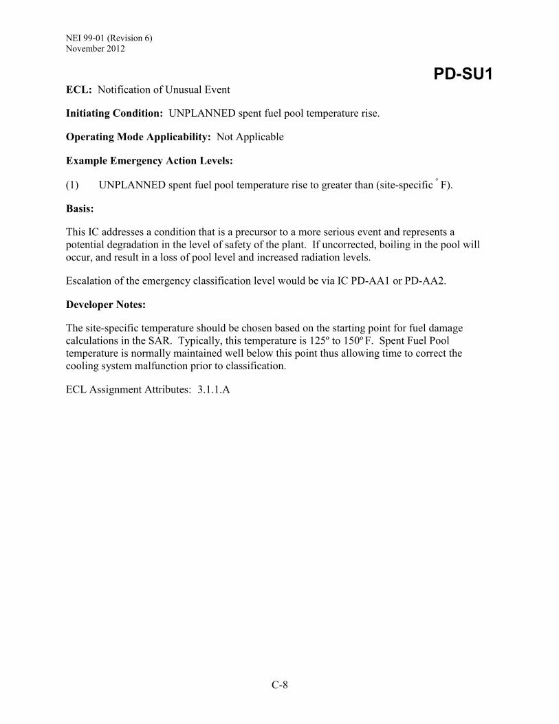
NEI 99-01 (Revision 6) November 2012
C-8
PD-SU1 ECL: Notification of Unusual Event
Initiating Condition: UNPLANNED spent fuel pool temperature rise.
Operating Mode Applicability: Not Applicable
Example Emergency Action Levels:
(1) UNPLANNED spent fuel pool temperature rise to greater than (site-specific ° F).
Basis:
This IC addresses a condition that is a precursor to a more serious event and represents a potential degradation in the level of safety of the plant. If uncorrected, boiling in the pool will occur, and result in a loss of pool level and increased radiation levels.
Escalation of the emergency classification level would be via IC PD-AA1 or PD-AA2.
Developer Notes:
The site-specific temperature should be chosen based on the starting point for fuel damage calculations in the SAR. Typically, this temperature is 125º to 150º F. Spent Fuel Pool temperature is normally maintained well below this point thus allowing time to correct the cooling system malfunction prior to classification.
ECL Assignment Attributes: 3.1.1.A

NEI 99-01 (Revision 6) November 2012
C-9
PD-HU1 ECL: Notification of Unusual Event
Initiating Condition: Confirmed SECURITY CONDITION or threat.
Operating Mode Applicability: Not Applicable
Example Emergency Action Levels: (1 or 2 or 3)
(1) A SECURITY CONDITION that does not involve a HOSTILE ACTION as reported by the (site-specific security shift supervision).
(2) Notification of a credible security threat directed at the site.
(3) A validated notification from the NRC providing information of an aircraft threat.
Basis:
This IC addresses events that pose a threat to plant personnel or the equipment necessary to maintain cooling of spent fuel, and thus represent a potential degradation in the level of plant safety. Security events which do not meet one of these EALs are adequately addressed by the requirements of 10 CFR § 73.71 or 10 CFR § 50.72. Security events assessed as HOSTILE ACTIONS are classifiable under IC PD-HA1.
Timely and accurate communications between Security Shift Supervision and the Control Room is essential for proper classification of a security-related event. Classification of these events will initiate appropriate threat-related notifications to plant personnel and OROs.
Security plans and terminology are based on the guidance provided by NEI 03-12, Template for the Security Plan, Training and Qualification Plan, Safeguards Contingency Plan [and Independent Spent Fuel Storage Installation Security Program].
EAL #1 references (site-specific security shift supervision) because these are the individuals trained to confirm that a security event is occurring or has occurred. Training on security event confirmation and classification is controlled due to the nature of Safeguards and 10 CFR § 2.39 information.
EAL #2 addresses the receipt of a credible security threat. The credibility of the threat is assessed in accordance with (site-specific procedure).
EAL #3 addresses the threat from the impact of an aircraft on the plant. The NRC Headquarters Operations Officer (HOO) will communicate to the licensee if the threat involves an aircraft. The status and size of the plane may also be provided by NORAD through the NRC. Validation of the threat is performed in accordance with (site-specific procedure).
Emergency plans and implementing procedures are public documents; therefore, EALs should not incorporate Security-sensitive information. This includes information that may be advantageous to a potential adversary, such as the particulars concerning a specific threat or threat location. Security-sensitive information should be contained in non-public documents such as the Security Plan.

NEI 99-01 (Revision 6) November 2012
C-10
Escalation of the emergency classification level would be via IC PD-HA1.
Developer Notes:
The (site-specific security shift supervision) is the title of the on-shift individual responsible for supervision of the on-shift security force. The (site-specific procedure) is the procedure(s) used by Control Room and/or Security personnel to determine if a security threat is credible, and to validate receipt of aircraft threat information. Emergency plans and implementing procedures are public documents; therefore, EALs should not incorporate Security-sensitive information. This includes information that may be advantageous to a potential adversary, such as the particulars concerning a specific threat or threat location. Security-sensitive information should be contained in non-public documents such as the Security Plan. With due consideration given to the above developer note, EALs may contain alpha or numbered references to selected events described in the Security Plan and associated implementing procedures. Such references should not contain a recognizable description of the event. For example, an EAL may be worded as “Security event #2, #5 or #9 is reported by the (site-specific security shift supervision).”
ECL Assignment Attributes: 3.1.1.A
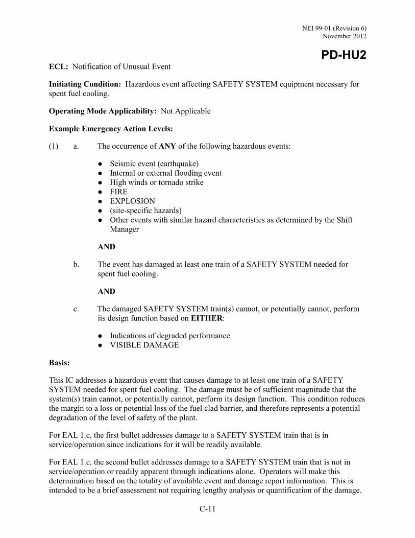
NEI 99-01 (Revision 6) November 2012
C-11
PD-HU2 ECL: Notification of Unusual Event
Initiating Condition: Hazardous event affecting SAFETY SYSTEM equipment necessary for spent fuel cooling.
Operating Mode Applicability: Not Applicable
Example Emergency Action Levels:
(1) a. The occurrence of ANY of the following hazardous events:
Seismic event (earthquake) Internal or external flooding event High winds or tornado strike FIRE EXPLOSION (site-specific hazards) Other events with similar hazard characteristics as determined by the Shift
Manager
AND
b. The event has damaged at least one train of a SAFETY SYSTEM needed for spent fuel cooling.
AND
c. The damaged SAFETY SYSTEM train(s) cannot, or potentially cannot, perform its design function based on EITHER:
Indications of degraded performance VISIBLE DAMAGE
Basis:
This IC addresses a hazardous event that causes damage to at least one train of a SAFETY SYSTEM needed for spent fuel cooling. The damage must be of sufficient magnitude that the system(s) train cannot, or potentially cannot, perform its design function. This condition reduces the margin to a loss or potential loss of the fuel clad barrier, and therefore represents a potential degradation of the level of safety of the plant.
For EAL 1.c, the first bullet addresses damage to a SAFETY SYSTEM train that is in service/operation since indications for it will be readily available.
For EAL 1.c, the second bullet addresses damage to a SAFETY SYSTEM train that is not in service/operation or readily apparent through indications alone. Operators will make this determination based on the totality of available event and damage report information. This is intended to be a brief assessment not requiring lengthy analysis or quantification of the damage.
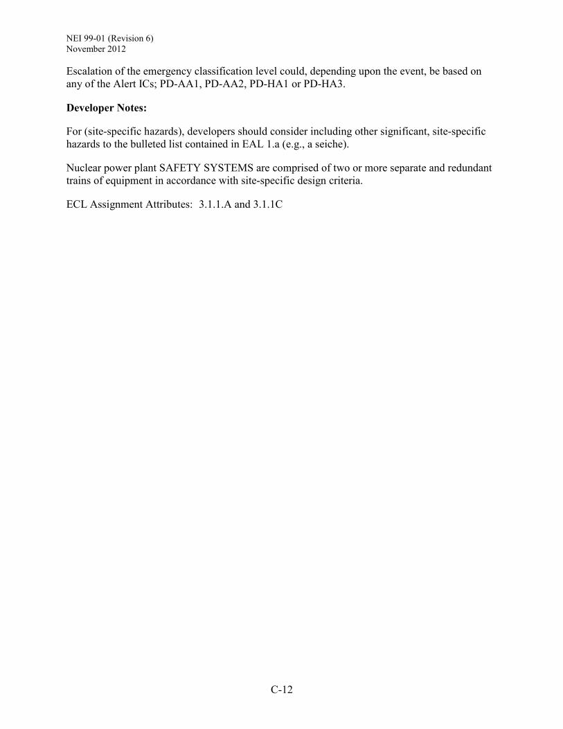
NEI 99-01 (Revision 6) November 2012
C-12
Escalation of the emergency classification level could, depending upon the event, be based on any of the Alert ICs; PD-AA1, PD-AA2, PD-HA1 or PD-HA3.
Developer Notes:
For (site-specific hazards), developers should consider including other significant, site-specific hazards to the bulleted list contained in EAL 1.a (e.g., a seiche).
Nuclear power plant SAFETY SYSTEMS are comprised of two or more separate and redundant trains of equipment in accordance with site-specific design criteria.
ECL Assignment Attributes: 3.1.1.A and 3.1.1C

NEI 99-01 (Revision 6) November 2012
C-13
PD-HU3 ECL: Notification of Unusual Event
Initiating Condition: Other conditions exist which in the judgment of the Emergency Director warrant declaration of a (NO)UE.
Operating Mode Applicability: Not Applicable
Example Emergency Action Levels:
(1) Other conditions exist which in the judgment of the Emergency Director indicate that events are in progress or have occurred which indicate a potential degradation of the level of safety of the plant or indicate a security threat to facility protection has been initiated. No releases of radioactive material requiring offsite response or monitoring are expected unless further degradation of safety systems occurs.
Basis:
This IC addresses unanticipated conditions not addressed explicitly elsewhere but that warrant declaration of an emergency because conditions exist which are believed by the Emergency Director to fall under the emergency classification level description for a NOUE.

NEI 99-01 (Revision 6) November 2012
C-14
PD-AA1 ECL: Alert
Initiating Condition: Release of gaseous or liquid radioactivity resulting in offsite dose greater than 10 mrem TEDE or 50 mrem thyroid CDE.
Operating Mode Applicability: Not Applicable
Example Emergency Action Levels: (1 or 2 or 3 or 4)
Notes: The Emergency Director should declare the Alert promptly upon determining that the
applicable time has been exceeded, or will likely be exceeded. If an ongoing release is detected and the release start time is unknown, assume that the
release duration has exceeded 15 minutes. If the effluent flow past an effluent monitor is known to have stopped due to actions to
isolate the release path, then the effluent monitor reading is no longer valid for classification purposes.
The pre-calculated effluent monitor values presented in EAL #1 should be used for emergency classification assessments until the results from a dose assessment using actual meteorology are available.
(1) Reading on ANY of the following radiation monitors greater than the reading shown for
15 minutes or longer:
(site-specific monitor list and threshold values)
(2) Dose assessment using actual meteorology indicates doses greater than 10 mrem TEDE or 50 mrem thyroid CDE at or beyond (site-specific dose receptor point).
(3) Analysis of a liquid effluent sample indicates a concentration or release rate that would result in doses greater than 10 mrem TEDE or 50 mrem thyroid CDE at or beyond (site-specific dose receptor point) for one hour of exposure.
(4) Field survey results indicate EITHER of the following at or beyond (site-specific dose receptor point):
Closed window dose rates greater than 10 mR/hr expected to continue for 60 minutes or longer.
Analyses of field survey samples indicate thyroid CDE greater than 50 mrem for one hour of inhalation.
Basis:
This IC addresses a release of gaseous or liquid radioactivity that results in projected or actual offsite doses greater than or equal to 1% of the EPA Protective Action Guides (PAGs). It includes both monitored and un-monitored releases. Releases of this magnitude represent an actual or potential substantial degradation of the level of safety of the plant as indicated by a

NEI 99-01 (Revision 6) November 2012
C-15
radiological release that significantly exceeds regulatory limits (e.g., a significant uncontrolled release). Radiological effluent EALs are also included to provide a basis for classifying events and conditions that cannot be readily or appropriately classified on the basis of plant conditions alone. The inclusion of both plant condition and radiological effluent EALs more fully addresses the spectrum of possible accident events and conditions. The TEDE dose is set at 1% of the EPA PAG of 1,000 mrem while the 50 mrem thyroid CDE was established in consideration of the 1:5 ratio of the EPA PAG for TEDE and thyroid CDE.
Classification based on effluent monitor readings assumes that a release path to the environment is established. If the effluent flow past an effluent monitor is known to have stopped due to actions to isolate the release path, then the effluent monitor reading is no longer valid for classification purposes.
Developer Notes:
While this IC may not be met absent challenges to the cooling of spent fuel, it provides classification diversity and may be used to classify events that would not reach the same ECL based on plant conditions alone.
The EPA PAGs are expressed in terms of the sum of the effective dose equivalent (EDE) and the committed effective dose equivalent (CEDE), or as the thyroid committed dose equivalent (CDE). For the purpose of these IC/EALs, the dose quantity total effective dose equivalent (TEDE), as defined in 10 CFR § 20, is used in lieu of “…sum of EDE and CEDE.…”.
The EPA PAG guidance provides for the use adult thyroid dose conversion factors; however, some states have decided to base protective actions on child thyroid CDE. Nuclear power plant ICs/EALs need to be consistent with the protective action methodologies employed by the States within their EPZs. The thyroid CDE dose used in the IC and EALs should be adjusted as necessary to align with State protective action decision-making criteria.
The “site-specific monitor list and threshold values” should be determined with consideration of the following:
Selection of the appropriate installed gaseous and liquid effluent monitors. The effluent monitor readings should correspond to a dose of 10 mrem TEDE or 50 mrem
thyroid CDE at the “site-specific dose receptor point” (consistent with the calculation methodology employed) for one hour of exposure.
Monitor readings will be calculated using a set of assumed meteorological data or atmospheric dispersion factors; the data or factors selected for use should be the same as those employed to calculate the monitor readings for IC PD-AU1.
The calculation of monitor readings will also require use of an assumed release isotopic mix; the selected mix should be the same as that employed to calculate monitor readings for IC PD-AU1.
Depending upon the methodology used to calculate the EAL values, there may be overlap of some values between different ICs. Developers will need to address this overlap by adjusting these values in a manner that ensures a logical escalation in the ECL.
NEI 99-01 (Revision 6) November 2012
C-16
The “site-specific dose receptor point” is the distance(s) and/or locations used by the licensee to distinguish between on-site and offsite doses. The selected distance(s) and/or locations should reflect the content of the emergency plan, and the procedural methodology used to determine offsite doses and Protective Action Recommendations. The variation in selected dose receptor points means there may be some differences in the distance from the release point to the calculated dose point from site to site.
Developers should research radiation monitor design documents or other information sources to ensure that 1) the EAL value being considered is within the usable response and display range of the instrument, and 2) there are no automatic features that may render the monitor reading invalid (e.g., an auto-purge feature triggered at a particular indication level).
It is recognized that the condition described by this IC may result in a radiological effluent value beyond the operating or display range of the installed effluent monitor. In those cases, EAL values should be determined with a margin sufficient to ensure that an accurate monitor reading is available. For example, an EAL monitor reading might be set at 90% to 95% of the highest accurate monitor reading. This provision notwithstanding, if the estimated/calculated monitor reading is greater than approximately 110% of the highest accurate monitor reading, then developers may choose not to include the monitor as an indication and identify an alternate EAL threshold.
Although the IC references TEDE, field survey results are generally available only as a “whole body” dose rate. For this reason, the field survey EAL specifies a “closed window” survey reading.
Indications from a real-time dose projection system are not included in the generic EALs. Many licensees do not have this capability. For those that do, the capability may not be within the scope of the plant Technical Specifications. A licensee may request to include an EAL using real-time dose projection system results; approval will be considered on a case-by-case basis.
Indications from a perimeter monitoring system are not included in the generic EALs. Many licensees do not have this capability. For those that do, these monitors may not be controlled and maintained to the same level as plant equipment, or within the scope of the plant Technical Specifications. In addition, readings may be influenced by environmental or other factors. A licensee may request to include an EAL using a perimeter monitoring system; approval will be considered on a case-by-case basis.
ECL Assignment Attributes: 3.1.2.C

NEI 99-01 (Revision 6) November 2012
C-17
PD-AA2 ECL: Alert
Initiating Condition: UNPLANNED rise in plant radiation levels that impedes plant access required to maintain spent fuel integrity.
Operating Mode Applicability: Not Applicable
Example Emergency Action Levels: (1 or 2)
(1) UNPLANNED dose rate greater than 15 mR/hr in ANY of the following areas requiring continuous occupancy to maintain control of radioactive material or operation of systems needed to maintain spent fuel integrity:
(site-specific area list)
(2) UNPLANNED Area Radiation Monitor readings or survey results indicate a rise by 100 mR/hr over NORMAL LEVELS that impedes access to ANY of the following areas needed to maintain control of radioactive material or operation of systems needed to maintain spent fuel integrity.
(site-specific area list)
Basis:
This IC addresses increased radiation levels that impede necessary access to areas containing equipment that must be operated manually or that requires local monitoring, in order to maintain systems needed to maintain spent fuel integrity. As used here, ‘impede’ includes hindering or interfering, provided that the interference or delay is sufficient to significantly threaten necessary plant access. It is this impaired access that results in the actual or potential substantial degradation of the level of safety of the plant.
This IC does not apply to anticipated temporary increases due to planned events.
Developer Notes:
The value of 15mR/hr is derived from the GDC 19 value of 5 rem in 30 days with adjustment for expected occupancy times. Although Section III.D.3 of NUREG-0737, Clarification of TMI Action Plan Requirements, provides that the 15 mR/hr value can be averaged over the 30 days, the value is used here without averaging, as a 30 day duration implies an event potentially more significant than an Alert.
The specified value of 100 mR/hr may be set to another value for a specific application with appropriate justification.
ECL Assignment Attributes: 3.1.2.C

NEI 99-01 (Revision 6) November 2012
C-18
PD-HA1 ECL: Alert
Initiating Condition: HOSTILE ACTION within the OWNER CONTROLLED AREA or airborne attack threat within 30 minutes.
Operating Mode Applicability: Not Applicable
Example Emergency Action Levels: (1 or 2)
(1) A HOSTILE ACTION is occurring or has occurred within the OWNER CONTROLLED AREA as reported by the (site-specific security shift supervision).
(2) A validated notification from NRC of an aircraft attack threat within 30 minutes of the site.
Basis:
This IC addresses the occurrence of a HOSTILE ACTION within the OWNER CONTROLLED AREA or notification of an aircraft attack threat. This event will require rapid response and assistance due to the possibility of the attack progressing to the PROTECTED AREA, or the need to prepare the plant and staff for a potential aircraft impact.
Timely and accurate communications between Security Shift Supervision and the Control Room is essential for proper classification of a security-related event.
Security plans and terminology are based on the guidance provided by NEI 03-12, Template for the Security Plan, Training and Qualification Plan, Safeguards Contingency Plan [and Independent Spent Fuel Storage Installation Security Program].
As time and conditions allow, these events require a heightened state of readiness by the plant staff and implementation of onsite protective measures (e.g., evacuation, dispersal or sheltering). The Alert declaration will also heighten the awareness of Offsite Response Organizations, allowing them to be better prepared should it be necessary to consider further actions.
This IC does not apply to incidents that are accidental events, acts of civil disobedience, or otherwise are not a HOSTILE ACTION perpetrated by a HOSTILE FORCE. Examples include the crash of a small aircraft, shots from hunters, physical disputes between employees, etc. Reporting of these types of events is adequately addressed by other EALs, or the requirements of 10 CFR § 73.71 or 10 CFR § 50.72.
EAL #1 is applicable for any HOSTILE ACTION occurring, or that has occurred, in the OWNER CONTROLLED AREA. This includes any action directed against an ISFSI that is located within the OWNER CONTROLLED AREA.
EAL #2 addresses the threat from the impact of an aircraft on the plant, and the anticipated arrival time is within 30 minutes. The intent of this EAL is to ensure that threat-related notifications are made in a timely manner so that plant personnel and OROs are in a heightened

NEI 99-01 (Revision 6) November 2012
C-19
state of readiness. This EAL is met when the threat-related information has been validated in accordance with (site-specific procedure).
The NRC Headquarters Operations Officer (HOO) will communicate to the licensee if the threat involves an aircraft. The status and size of the plane may be provided by NORAD through the NRC.
In some cases, it may not be readily apparent if an aircraft impact within the OWNER CONTROLLED AREA was intentional (i.e., a HOSTILE ACTION). It is expected, although not certain, that notification by an appropriate Federal agency to the site would clarify this point. In this case, the appropriate federal agency is intended to be NORAD, FBI, FAA or NRC. The emergency declaration, including one based on other ICs/EALs, should not be unduly delayed while awaiting notification by a Federal agency.
Emergency plans and implementing procedures are public documents; therefore, EALs should not incorporate Security-sensitive information. This includes information that may be advantageous to a potential adversary, such as the particulars concerning a specific threat or threat location. Security-sensitive information should be contained in non-public documents such as the Security Plan.
Developer Notes:
The (site-specific security shift supervision) is the title of the on-shift individual responsible for supervision of the on-shift security force. Emergency plans and implementing procedures are public documents; therefore, EALs should not incorporate Security-sensitive information. This includes information that may be advantageous to a potential adversary, such as the particulars concerning a specific threat or threat location. Security-sensitive information should be contained in non-public documents such as the Security Plan.
With due consideration given to the above developer note, EALs may contain alpha or numbered references to selected events described in the Security Plan and associated implementing procedures. Such references should not contain a recognizable description of the event. For example, an EAL may be worded as “Security event #2, #5 or #9 is reported by the (site-specific security shift supervision).”
See the related Developer Note in Appendix B, Definitions, for guidance on the development of a scheme definition for the OWNER CONTROLLED AREA.
ECL Assignment Attributes: 3.1.2.D

NEI 99-01 (Revision 6) November 2012
C-20
PD-HA3 ECL: Alert
Initiating Condition: Other conditions exist which in the judgment of the Emergency Director warrant declaration of an Alert.
Operating Mode Applicability: Not Applicable
Example Emergency Action Levels:
(1) Other conditions exist which in the judgment of the Emergency Director indicate that events are in progress or have occurred which involve an actual or potential substantial degradation of the level of safety of the plant or a security event that involves probable life threatening risk to site personnel or damage to site equipment because of HOSTILE ACTION. Any releases are expected to be limited to small fractions of the EPA Protective Action Guideline exposure levels.
Basis:
This IC addresses unanticipated conditions not addressed explicitly elsewhere but that warrant declaration of an emergency because conditions exist which are believed by the Emergency Director to fall under the emergency classification level description for an Alert.

![Quality Assurance Program Description · NEI-06-14 Revision 98 [Nuclear Development] Quality Assurance Program Description v [Company Name] POLICY STATEMENT [Company Name] ([Company](https://img.pdfslide.net/doc/110x75/6008c971c812e421ad757625/quality-assurance-program-description-nei-06-14-revision-98-nuclear-development.jpg)


![NEI 16-16 Guidance for Addressing Digital Common Cause ... · Nuclear Energy Institute, 1201 F Street N. W., Suite 1100, Washington D.C. (202.739.8000) NEI 16-16 [Draft 1] Nuclear](https://img.pdfslide.net/doc/110x75/5f047ee47e708231d40e413a/nei-16-16-guidance-for-addressing-digital-common-cause-nuclear-energy-institute.jpg)


![NEI 10-05 [Revision 0] - Nuclear Regulatory CommissionNuclear Energy Institute, 1776 I Street N. W., Suite 400, Washington D.C. (202.739.8000) NEI 10-05 [Revision 0] Nuclear Energy](https://img.pdfslide.net/doc/110x75/6029a18ac1e47f08dc0073ef/nei-10-05-revision-0-nuclear-regulatory-commission-nuclear-energy-institute.jpg)


![NEI 03-01 [Revision 2] · 2012-12-01 · NEI 03-01 (Revision 2) Draft September 2008 ACKNOWLEDGEMENTS This document, NEI 03-01, Nuclear Power Plant Access Authorization Program, was](https://img.pdfslide.net/doc/110x75/5e88e8ab72cf501305111bda/nei-03-01-revision-2-2012-12-01-nei-03-01-revision-2-draft-september-2008.jpg)