Embed Size (px)
Citation preview

Nuclear Thermal Rocket Simulation in NPSS
Michael L. Belair∗, Charles J. Sarmiento†, and Thomas M. Lavelle‡
NASA Glenn Research Center, Cleveland, OH, 44135
Four nuclear thermal rocket (NTR) models have been created in the Numerical Propul-sion System Simulation (NPSS) framework. The models are divided into two categories.One set is based upon the ZrC-graphite composite fuel element and tie tube-style reactordeveloped during the Nuclear Engine for Rocket Vehicle Application (NERVA) project inthe late 1960s and early 1970s. The other reactor set is based upon a W-UO2 ceramic-metallic (CERMET) fuel element. Within each category, a small and a large thrust engineare modeled. The small engine models utilize RL-10 turbomachinery performance mapsand have a thrust of approximately 33.4 kN (7,500 lbf). The large engine models utilizescaled RL-60 turbomachinery performance maps and have a thrust of approximately 111.2kN (25,000 lbf). Power deposition profiles for each reactor were obtained from a detailedMonte Carlo N-Particle (MCNP5) model of the reactor cores. Performance factors such asthermodynamic state points, thrust, specific impulse, reactor power level, and maximumfuel temperature are analyzed for each engine design.
Nomenclature
AR Area RatioCERMET Ceramic-Metallic fuel elementDRA Design Reference Architectureg Acceleration of gravity at sea levelγ Ratio of specific heatsGRC Glenn Research CenterIsp Specific ImpulsekN kilownewtons forcelbf pounds forceMCNP Monte Carlo N-Particle transport codeMW MegawattsMW Molecular WeightNCPS Nuclear Cryogenic Propulsion StageNERVA Nuclear Engine for Rocket Vehicle ApplicationNESS Nuclear Engine System SimulationNPSS Numerical Propulsion System Simulation codeNTP Nuclear Thermal PropulsionNTR Nuclear Thermal RocketPe Exhaust PressurePi Inlet PressureR Universal Gas ConstantSNRE Small Nuclear Rocket EngineT Temperature
∗Liquid Propulsion System Engineer, 21000 Brookpark Road, MS 86-8, Cleveland, OH, 44135, AIAA Member†Liquid Propulsion System Engineer, 21000 Brookpark Road, MS 86-8, Cleveland, OH, 44135‡Propulsion Systems Engineer, 21000 Brookpark Road, MS 86, Cleveland, OH, 44135
1 of 15
American Institute of Aeronautics and Astronautics
https://ntrs.nasa.gov/search.jsp?R=20140009572 2018-05-26T18:27:57+00:00Z
I. Introduction
Nuclear thermal propulsion (NTP) is identified as the preferred propulsion technology for manned mis-sions to Mars in NASA’s Design Reference Architecture (DRA) 5.0.1 NTP is the preferred propulsion
technology because it has heritage and higher performance than current propulsion systems available at thethrust levels necessary for manned missions. The Nuclear Cryogenic Propulsion Stage (NCPS) project isengaged in conceptual design of a small 33.4 kN (7,500 lbf) and a full-size/large 111.2 kN (25,000 lbf) classnuclear rocket. The small engine could be used for a flight demonstration mission as well as possible roboticprobe missions. The large nuclear engine is intended to be used in a clustered configuration for humanexploration missions.2
In support of the NCPS project, the NASA Glenn Research Center (GRC) has been working to modelfour nuclear thermal rockets in the Numerical Propulsion System Simulation (NPSS) framework. The mainintent of this work is to analyze the overall system performance and operation of a nuclear thermal rocket.Existing turbomachinery design were simulated to mitigate the eventual cost of a turbomachinery develop-ment effort. The four engine models are broken into two categories based on the fuel element type. One fuelelement is based on the design from the Nuclear Engine for Rocket Vehicle Application (NERVA) projectand another is a ceramic-metallic (CERMET) fuel element design. The small engine models utilize a RL-10type hydrogen turbopump and the larger engine models attempt to utilize a dual RL-60 type hydrogenturbopump configuration.
The Rover program which included the Nuclear Engine for Rocket Vehicle Application (NERVA) projectdemonstrated the concept of a nuclear rocket was feasible. The Rover/NERVA program was quite successfuland developed twenty rocket reactors that were built and ground tested. The reactor design that resultedfrom the NERVA project is the basis for one of the reactor sets analyzed.3
A. Advantages of Nuclear Propulsion
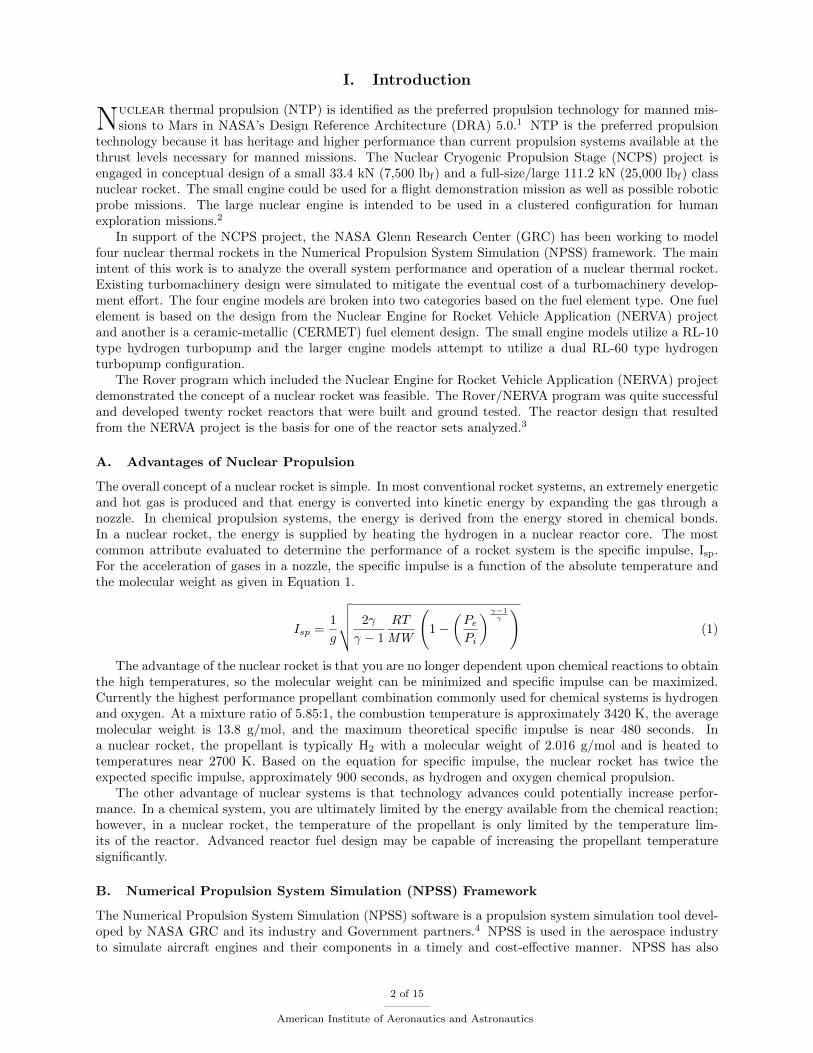
The overall concept of a nuclear rocket is simple. In most conventional rocket systems, an extremely energeticand hot gas is produced and that energy is converted into kinetic energy by expanding the gas through anozzle. In chemical propulsion systems, the energy is derived from the energy stored in chemical bonds.In a nuclear rocket, the energy is supplied by heating the hydrogen in a nuclear reactor core. The mostcommon attribute evaluated to determine the performance of a rocket system is the specific impulse, Isp.For the acceleration of gases in a nozzle, the specific impulse is a function of the absolute temperature andthe molecular weight as given in Equation 1.
Isp =1
g
√√√√ 2γ
γ − 1
RT
MW
(1 −
(Pe
Pi
) γ−1γ
)(1)
The advantage of the nuclear rocket is that you are no longer dependent upon chemical reactions to obtainthe high temperatures, so the molecular weight can be minimized and specific impulse can be maximized.Currently the highest performance propellant combination commonly used for chemical systems is hydrogenand oxygen. At a mixture ratio of 5.85:1, the combustion temperature is approximately 3420 K, the averagemolecular weight is 13.8 g/mol, and the maximum theoretical specific impulse is near 480 seconds. Ina nuclear rocket, the propellant is typically H2 with a molecular weight of 2.016 g/mol and is heated totemperatures near 2700 K. Based on the equation for specific impulse, the nuclear rocket has twice theexpected specific impulse, approximately 900 seconds, as hydrogen and oxygen chemical propulsion.
The other advantage of nuclear systems is that technology advances could potentially increase perfor-mance. In a chemical system, you are ultimately limited by the energy available from the chemical reaction;however, in a nuclear rocket, the temperature of the propellant is only limited by the temperature lim-its of the reactor. Advanced reactor fuel design may be capable of increasing the propellant temperaturesignificantly.
B. Numerical Propulsion System Simulation (NPSS) Framework
The Numerical Propulsion System Simulation (NPSS) software is a propulsion system simulation tool devel-oped by NASA GRC and its industry and Government partners.4 NPSS is used in the aerospace industryto simulate aircraft engines and their components in a timely and cost-effective manner. NPSS has also
2 of 15
American Institute of Aeronautics and Astronautics
been expanded to spacecraft applications due to its flexible nature. It allows developers to create their owncustom elements that can be used in system simulations. For the NCPS modeling project, custom reactorand tie tube elements were developed to interface in the NPSS framework. The theory behind the reactorand tie tube thermodynamics and fluid mechanics is summarized elsewhere.5,6
II. Turbomachinery Modeling
A. RL-10 Hydrogen Pump and Turbine
The small class of engines utilizes the RL-10 hydrogen pump and turbine to power the engine. All RL-10variants operate based on an expander cycle where the liquid hydrogen is heated in the regenerative nozzleand chamber and used to drive the turbine. The same type of cycle can be run for a nuclear rocket wherethe heat is obtained from the nozzle cooling section and the tie tubes. As of 2012, there are two variants ofthe RL-10 in use.7 The two engines are summarized in Table 1.
Table 1. RL-10 Variants7
RL-10A4-2 RL-10B-2
Propellants LOX/LH2 LOX/LH2
Thrust (kN) 99.2 110.1
Chamber Pressure (MPa) 4.21 4.41
Mixture Ratio 5.5:1 5.85:1
Specific Impulse (seconds) 451 464
Area Ratio 84:1 285:1
Hydrogen Mass Flow Rate*(kg/sec) 3.45 3.54
* Calculated based on thrust, specific impulse and mixture ratio.
The decision to simulate RL-10 turbomachinery was made because the hydrogen flow rate for the smallnuclear rocket engine is very similar to the hydrogen flow rate of the RL-10. The expected flow rate neededfor the small engine class is approximately 3.81 kg/sec based on a thrust of 33.4 kN and a specific impulseof 900 seconds. This flow rate represents an increase less than ten percent from the RL-10B-2 design.
B. RL-60 Hydrogen Pump and Turbine
The large class of nuclear engines, 111.2 kN thrust, utilizes the turbomachinery from the RL-60 design topump the liquid hydrogen through the reactor core. The RL-60 is an upgraded design from the RL-10. TheRL-60 was designed to have a thrust of 266.9 kN and a specific impulse of 465 seconds. The mixture ratioof the RL-60 was intended to be operated at a range of 5.0 to 6.0:1. The hydrogen flow rate through theengine is calculated to be 8.35-9.75 kg/sec. This flow rate is smaller than the expected flow rate of the largenuclear engines. The large nuclear engines are expected to have a flow rate of approximately 12.7 kg/secbased on a thrust of 111.2 kN and a specific impulse near 900 seconds.
Since there is approximately a 30-40 percent greater mass flow rate than the design level of the RL-60, itwas decided to use a dual turbopump configuration. In this configuration, two RL-60 turbopump assemblieswill operate in parallel at approximately 70 percent capacity in order to provide the necessary mass flowrate. In the event of a failure of one turbopump assembly, the engine could be operated at a lower powerand thrust level if desirable.
III. Fuel Element Descriptions
A. NERVA
The NERVA derived engines utilize the (U,Zr)C-graphite hexagonal fuel element with structural support tietubes that was the baseline design for the Small Nuclear Rocket Engine (SNRE).8 The fuel element has aflat to flat measurement of 1.905 cm and is 88.9 cm long for the small engine and 132.1 cm long for thelarge engine. Each fuel element contains 19 coolant passages with 0.257 cm diameter holes for the hydrogen
3 of 15
American Institute of Aeronautics and Astronautics

coolant. The outer surface of the fuel element and the interior of the coolant channels are coated witha protective layer of ZrC. The outer surface is coated to a thickness of 50 micrometers, and the coolantchannels have a tapered coating varying from 50 micrometers at the inlet to 150 micrometers at the exit.More information on the NERVA derived fuel elements can be found in the references written by Schnitlzerand Fittje.9,10 Figure 1 below shows the details for the fuel element and tie tube geometry.10
Figure 1. NERVA Derived Fuel Element and Tie Tube
B. ANL-200 CERMET
The CERMET engines utilize the fuel element known as ANL-200. The fuel element is composed of Gd2O3
stabilized UO2 particles in a tungsten matrix. The fuel element has a flat to flat measurement of 2.774 cmand is 60.96 cm long for the small engine and 86.36 cm long for the large engine. Each fuel element contains61 coolant passages with 0.170 cm diameter holes for the hydrogen coolant. The outer surface of the fuelelement and the interior of the coolant channels are coated with a 0.01778 cm protective layer of W-25 wt%Re. Figure 2 below shows the general arrangement of the fuel element in a reactor core.11
Figure 2. ANL-200 Fuel Element
4 of 15
American Institute of Aeronautics and Astronautics
IV. Small NERVA Derived Engine
A. Engine Configuration
Since thrust is proportional to reactor power, the small engine is modeled in order to have enough thermalpower to produce approximately 33.4 kN of thrust. All of the engines tested during the NERVA project weredesigned for much higher thrust levels; Peewee was the smallest at 25 klbf .
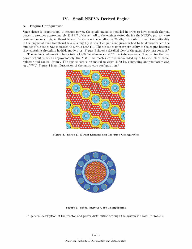
3 In order to maintain criticalityin the engine at such low thrust levels, a slightly different engine configuration had to be devised where thenumber of tie tubes was increased to a ratio near 1:1. The tie tubes improve criticality of the engine becausethey contain a zirconium hydride moderator. Figure 3 shows a detailed view of the general pattern concept.9
The engine configuration has a total of 260 fuel elements and 251 tie tube elements. The reactor thermalpower output is set at approximately 162 MW. The reactor core is surrounded by a 14.7 cm thick radialreflector and control drums. The engine core is estimated to weigh 1432 kg, containing approximately 27.5kg of 235U. Figure 4 is an illustration of the entire core configuration.9
Figure 3. Dense (1:1) Fuel Element and Tie Tube Configuration
Figure 4. Small NERVA Core Configuration
A general description of the reactor and power distribution through the system is shown in Table 2.
5 of 15
American Institute of Aeronautics and Astronautics

Table 2. Small NERVA Derived Engine Summary
Description Value Units
Number of Fuel Elements 260 NA
Number of Tie Tubes 251 NA
Avg. Power Deposited Fuel Element 0.586579 MW
Reactor Total Power 161.6 MW
Fuel Element Hydrogen Heating 140.7 MW
Tie Tube Hydrogen Heating 16.6 MW
Conduction from Fuel Elements 11.78 MW
Nuclear Deposited 4.84 MW
Control Drum Hydrogen Heating 3.45 MW
B. Engine Flow Path
One of the main design constraints of a nuclear rocket system is obtaining enough thermal energy to run theturbomachinery. For the NERVA derived engines, this is typically not an issue because the pressure dropthrough the engine is relatively low and there is plenty of available thermal energy from the tie tubes. Infact, there is significantly more thermal energy available than necessary to run the turbomachinery. In orderto keep the turbine inlet temperature closer to the heritage RL-10 temperatures, an innovative flow pathhad to be considered to lower this temperature as much as possible.
First, the liquid hydrogen leaves the tank and passes through the fuel inlet valve. The hydrogen is thencompressed through a two stage pump. Then the flow is split into two parallel paths. Part of the flow isdirected to the tie tubes which provide structural support for the reactor as well as criticality. The remainingflow enters the nozzle and chamber regenerative cooling section. After the flow leaves the regenerative coolingsection, it is directed up along the reactor to cool the control drums and radial reflectors. Once the flowexits the control drum/ radial reflector, it is recombined with a small fraction of the flow from the tie tubes.This combination is sent to the turbine. Some of the flow is allowed to bypass the turbine in order to controlthe flow rate of hydrogen through the pumps. Once the flow from the turbine, turbine bypass valve, andremaining tie tube flow recombine, it is directed to the reactor inlet. The gas that enters the reactor is thensuperheated to extremely high temperatures before it is exhausted through a nozzle. An illustration of theflow path can be seen in the model results for this engine, shown in Figure 5.
C. Model Results
The model was run to obtain a chamber pressure of 4.14 MPa (600 psia) and a peak fuel temperature of 2860K (5148 R). This specific state was chosen due to turbomachinery pump discharge pressure limitations andfuel element temperature limitations. It should be noted that the pressure drop through the regenerativecooling sections are estimated using resistance values that scale the pressure drop with the mass flow rateof the engine.
6 of 15
American Institute of Aeronautics and Astronautics

Figure 5. Small NERVA System Results
A comparison summary of the reactor is shown in Table 4. It should be noted that the component masssection is only an estimate. The reactor mass is estimated based on the results from the MCNP analysis.9
The pressure vessel, nozzle, and other numbers are based on scaling factors developed during the NERVAproject. The scaling factors are used to estimate mass as a function of the thrust and the overall size of thereactor core.
D. Discussion
There were several difficulties in the design of this engine. The biggest issue to resolve was the temperatureof the hydrogen entering the turbine. Since the RL-10 operates on an expander cycle, the temperaturesexperienced by the turbomachinery are quite low. However, the total energy available from the smallNERVA engine design is much greater than necessary. This is due to the large fraction of tie tubes in theengine that are necessary to maintain criticality at such a low thrust level. In order to compensate for this, asmall bleed from the tie tubes was used rather than the mixing the entire flow. However, this design featureintroduces further risk since it complicates the flow path of the engine and also results in a very high tie tubeoutlet temperature. Further analysis is necessary to see if the tie tube elements can withstand the thermalstress from this high temperature environment.
As shown in Table 4, the engine achieved a thrust to weight ratio of 1.96 and a specific impulse of approx-imately 900 seconds. The specific impulse is primarily driven by the maximum allowable fuel temperature.In this analysis, the assumed maximum fuel temperature was 2860 K (5148 R). The thrust to weight of theengine is primarily related to the mass of the reactor core since this is the largest contributor. A lower thrustto weight is another complication from the low thrust level. A low thrust level requires more tie tubes andlarger radial reflectors. This significantly reduces the thrust to weight of this engine. More work will need
7 of 15
American Institute of Aeronautics and Astronautics

to be performed to identify if the reactor mass can be reduced by returning to a 2:1 fuel element to tie tuberatio from the current 1:1 ratio with some other approach to enhance criticality.
V. Large NERVA Derived Engine
A. Engine Configuration
The large engine is designed to produce enough thermal power to generate approximately 112.1 kN of thrust.Since this engine is much larger than the 33.4 kN NERVA derived engine, fewer tie tubes are needed to provideadequate criticality. For this engine, the fuel element to tie tube ratio was changed to approximately 2:1which is the ratio studied for the small nuclear rocket engine (SNRE). Figure 6 shows a detailed view ofthe general pattern concept.9 In total, the engine has 564 fuel elements and 241 tie tube elements with atotal thermal power of 555 MW. The reactor core is surrounded by 14.7 cm thick radial reflector and controldrums. The core is estimated to have a total mass of 2645 kg, containing 36.8 kg of 235U.
Figure 6. SNRE (2:1) Fuel Element and Tie Tube Configuration
The fuel element to tie tube pattern shown in Figure 6 is repeated throughout the reactor. Near the edgeof the core, there are beryllium filler elements that are used to increase criticality and to make to the corecircular. The power distribution in this reactor is given in Table 3.
Table 3. Large NERVA Derived Engine Summary
Description Value Units
Number of Fuel Elements 564 NA
Number of Tie Tubes 241 NA
Avg. Power Deposited Fuel Element 0.9386027 MW
Reactor Total Power 555 MW
Fuel Element Hydrogen Heating 529.3 MW
Tie Tube Hydrogen Heating 39.1 MW
Conduction from Fuel Elements 27.1 MW
Nuclear Deposited 12.0 MW
Control Drum Hydrogen Heating 10.9 MW
B. Engine Flow Path
As with the small NERVA engine, there is plenty of thermal energy available to power the turbomachinery.The main difference between the small engine and the large engine is that the engine is operated with dual
8 of 15
American Institute of Aeronautics and Astronautics
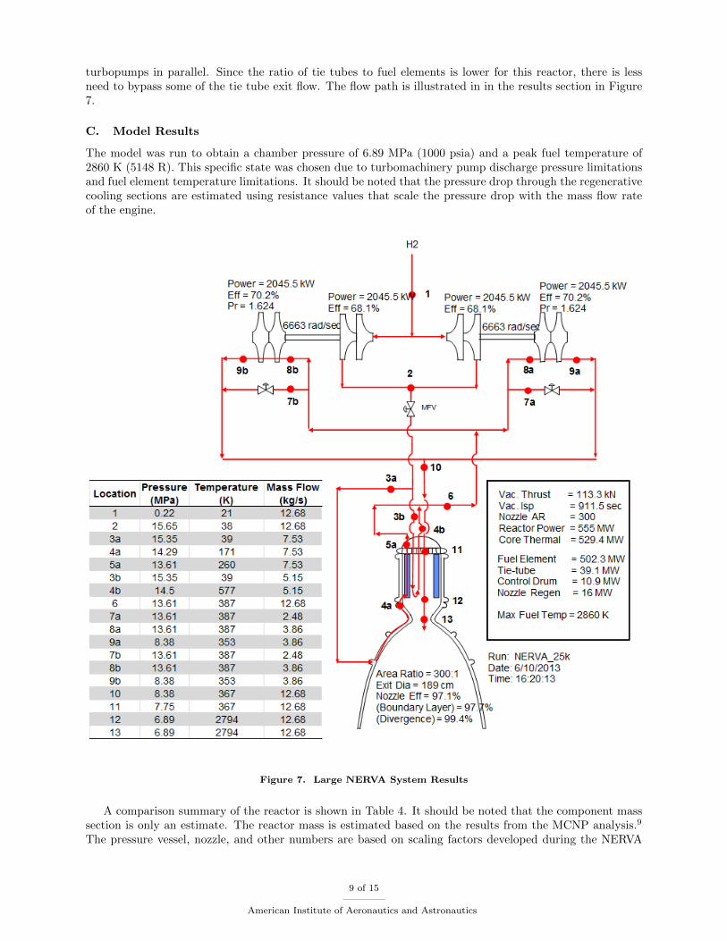
turbopumps in parallel. Since the ratio of tie tubes to fuel elements is lower for this reactor, there is lessneed to bypass some of the tie tube exit flow. The flow path is illustrated in in the results section in Figure7.
C. Model Results
The model was run to obtain a chamber pressure of 6.89 MPa (1000 psia) and a peak fuel temperature of2860 K (5148 R). This specific state was chosen due to turbomachinery pump discharge pressure limitationsand fuel element temperature limitations. It should be noted that the pressure drop through the regenerativecooling sections are estimated using resistance values that scale the pressure drop with the mass flow rateof the engine.
Figure 7. Large NERVA System Results
A comparison summary of the reactor is shown in Table 4. It should be noted that the component masssection is only an estimate. The reactor mass is estimated based on the results from the MCNP analysis.9
The pressure vessel, nozzle, and other numbers are based on scaling factors developed during the NERVA
9 of 15
American Institute of Aeronautics and Astronautics

project. The scaling factors are used to estimate mass as a function of the thrust and the overall size of thereactor core.
D. Discussion
One major concern for the NERVA derived engines is that the turbine inlet temperatures may exceed thenominal temperatures experienced in an expander cycle. As with the small NERVA derived engine, the largeengine transfers a significant amount of energy to the hydrogen in the tie tubes. As discussed before, thisis not considered as much of an issue for the large engine since the fuel element to tie tube ratio is greaterwhich lowers the turbine inlet temperature.
Another interesting result is that the specific impulse of the large engine is greater than the small engineby approximately 12 seconds. Both the small and large NERVA derived engines were analyzed with anassumed peak fuel temperature of 2860 K (5148 R). The higher specific impulse of the large engine isattributed to the longer fuel elements which have a greater heat transfer area. This larger area results ina lower thermal gradient between the fuel element and hydrogen coolant. The large engine also has muchgreater performance than the small engine in terms of thrust to weight. This is mostly attributed to thelarger fuel element to tie tube ratio which resulted in a approximately half the number of reactor elementsper unit thrust.
VI. Small ANL-200 Engine
A. Engine Configuration
The small CERMET engine is based on the ANL-200 fuel element design. The engine core contains a totalof 121 fuel elements for a total reactor thermal power of 160 MW.9 Since this is a fast spectrum reactor,no neutron moderation is required and the core is only composed of fuel elements. The reactor core issurrounded by a 10 cm thick BeO radial reflector as well as control drums to improve criticality. In order toreduce neutron leakage, there is a 15.24 cm axial reflector at the inlet of the reactor core. The reactor coreis estimated to have a mass of 1000 kg and contains 177.3 kg of 235U.
B. System Results
The small CERMET engine utilizes a flow path that is nearly identical to the flow path for the small NERVAderived engine. The only difference is that the CERMET engine does not have a parallel flow for tie tubessince there are no tie tubes in the system. The simulation set point was a chamber pressure of 3.79 MPa(550 psia) and a maximum fuel temperature of 2860 K (5148 R). In this system, the chamber pressure islimited due to the available energy to run the turbomachinery.
10 of 15
American Institute of Aeronautics and Astronautics

Figure 8. Small ANL-200 Engine System Results
A comparison summary of the reactor is shown in Table 4. It should be noted that the component masssection is only an estimate. The reactor mass is estimated based on the results from the MCNP analysis.9
The pressure vessel, nozzle, and other numbers are based on scaling factors developed during the NERVAproject. The scaling factors are used to estimate mass as a function of the thrust and the overall size of thereactor core.
C. Discussion
The small ANL-200 CERMET engine achieves a thrust of 33.8 kN (7591 lbf) and a specific impulse of885.4 seconds. The specific impulse is lower than the comparable small NERVA derived engine primarilybecause the chamber temperature is lower for the CERMET engine for the same peak fuel temperature.This is likely because the fuel element is thirty percent shorter than the NERVA fuel element which resultsin a higher thermal gradient between the fuel element and the hydrogen gas. The major concern for theCERMET engine is the available thermal energy to run the turbomachinery. In this analysis, the maximumchamber pressure attainable is near the operation point, 3.79 MPa (550 psia). This occurs primarily becausethe CERMET engine does not have regeneratively cooled tie tubes to increase propellant temperature. TheCERMET engine also has approximately one third of the energy deposition in the reflector and control drumsas compared to the NERVA derived engine. The amount of available energy is an issue when attempting toscale this design to a higher thrust level.
The small CERMET engine achieves a higher thrust to weight ratio than the small NERVA engine. Thisis primarily because the CERMET engine is more compact since it does not require tie tubes. The majorityof the mass in any system is the reactor core. Although CERMET fuel is more dense, the smaller volume coreis lighter and requires a lighter structure, radial reflector, and pressure vessel. All of these factors contributeto making the reactor substantially lighter than the comparable NERVA engine.
11 of 15
American Institute of Aeronautics and Astronautics
VII. Large ANL-200 Engine
A. Engine Configuration
The large CERMET engine is also based on the ANL-200 fuel element design. The reactor design analyzedis regarded as the radial growth option since the additional power compared to the small engine is obtainedprimarily by adding fuel elements. However, the fuel element length was also extended to 86.36 cm (34inches). The engine core consists of 241 fuel elements for a total reactor power of 513 MW. The reactor coreis surrounded by a 10 cm thick radial reflector as well as control drums to improve criticality. In order toreduce neutron leakage, there is a 15.24 cm axial reflector at the inlet of the reactor core. The reactor coreis estimated to have a mass of 2356 kg and contain 376.7 kg of 235U.
B. System Results
The overall engine system for the large ANL-200 reactor is based around a hot bleed cycle rather than thetypical expander cycle. This is due to a combination of factors. First, lack of sufficient thermal energyfor the turbomachinery in the CERMET systems results in a limit to the maximum thrust obtainable.Secondly, the reactor design for the large ANL-200 engine is an exasperating condition. In order to maintaina relatively compact engine core diameter, the fuel element had to be extended to 86.36 cm from 60.96cm which correspondingly increased the power per fuel element. The combination of increased length andincreased power per fuel element greatly increased the pressure drop across the reactor and therefore requireda higher pump discharge pressure.
In order to obtain the necessary energy to drive the turbomachinery, a hot bleed cycle had to be used.However, the hot bleed cycle reduces the average specific impulse of the system by as much as 65 secondsas illustrated in Figure 9. The hot bleed cycle is implemented by mixing a portion of the flow exiting thecontrol drum/reflector cooling loop with a bleed from the outlet of the reactor core. The ratio of cool tohot flow was proportioned in order to obtain a turbine inlet temperature of 833 K (1500 R). The turbineexhaust is directed through a 2:1 area ratio nozzle in order to recuperate some of the losses from a hot bleedcycle. The remaining flow from the control drum/reflector outlet is directly fed into the reactor core. Theresults are shown in Figure 9 and Table 4.
12 of 15
American Institute of Aeronautics and Astronautics
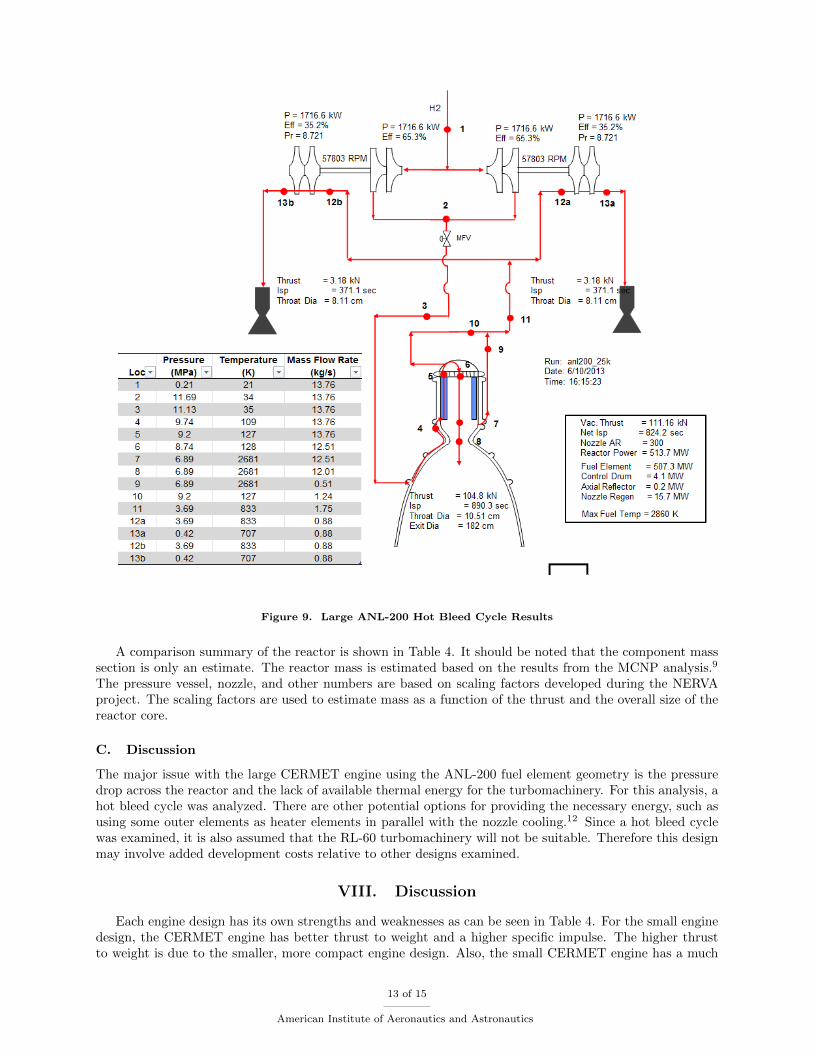
Figure 9. Large ANL-200 Hot Bleed Cycle Results
A comparison summary of the reactor is shown in Table 4. It should be noted that the component masssection is only an estimate. The reactor mass is estimated based on the results from the MCNP analysis.9
The pressure vessel, nozzle, and other numbers are based on scaling factors developed during the NERVAproject. The scaling factors are used to estimate mass as a function of the thrust and the overall size of thereactor core.
C. Discussion
The major issue with the large CERMET engine using the ANL-200 fuel element geometry is the pressuredrop across the reactor and the lack of available thermal energy for the turbomachinery. For this analysis, ahot bleed cycle was analyzed. There are other potential options for providing the necessary energy, such asusing some outer elements as heater elements in parallel with the nozzle cooling.12 Since a hot bleed cyclewas examined, it is also assumed that the RL-60 turbomachinery will not be suitable. Therefore this designmay involve added development costs relative to other designs examined.
VIII. Discussion
Each engine design has its own strengths and weaknesses as can be seen in Table 4. For the small enginedesign, the CERMET engine has better thrust to weight and a higher specific impulse. The higher thrustto weight is due to the smaller, more compact engine design. Also, the small CERMET engine has a much
13 of 15
American Institute of Aeronautics and Astronautics

simpler flow path design than the NERVA derived engine since it does not have tie tubes. However, thesmall CERMET engine requires over six times the amount of highly enriched 235U. If the cost or availabilityof enriched uranium is a major contributor to the engine, this may preclude the use of a CERMET engine.
When the desired thrust is increased to 112.1 kN (25 klbf), the benefits of CERMET seen in the smallengine start to decrease. This is primarily driven by the high pressure drop across the high thrust CERMETcore and the limited available energy for the turbopump operation. In order to get the engine cycle balanceto close, a hot bleed cycle was adopted which lowered the overall specific impulse of the engine and increasedthe complexity of the design. Not only is the performance of the engine worse than the large NERVA engine,it also requires approximately ten times the amount of enriched uranium. However, a lower pressure dropand a reduction of enriched uranium might be achieved by redesigning the fuel element and reactor core.
Table 4. Engine Comparison
Description SmallNERVA
SmallCERMET
LargeNERVA
LargeCERMET
Units
Reactor
Active Fuel Length 88.9 60.96 132 86.36 cm
Radial Reflector Thickness 14.7 10 14.7 10 cm
Axial Reflector Thickness – 15.24 – 15.24 cm
Engine Diameter 87.7 55 98.5 68 cm
Element Pattern Type Dense – 2:1 –
Number of Fuel Elements 260 121 564 241
Number of Tie Tube Elements 251 – 241 –235U mass 27.5 177.3 36.8 376.7 kg
Component Masses
Reactor 1435 1215 2645 2722 kg
Pressure Vessel 110 50 280 150 kg
Nozzle 115 115 240 270 kg
Turbomachinery-Piping 40 40 90 135 kg
Gimbal 30 30 50 50 kg
Engine Total 1730 1450 3305 3327 kg
Engine System
Thrust 33.2 33.8 113.3 111.2 kN
Maximum Fuel Temperature 2860 2860 2860 2860 K
Chamber Inlet Temperature 2756 2682 2794 2681 K
Chamber Pressure 4.14 3.79 6.89 6.89 MPa
Nozzle Expansion Ratio 300 300 300 300
Specific Impulse 899.6 885.4 911.5 824.2 sec
Thrust to Weight 1.96 2.38 3.49 3.41
IX. Conclusions
Four nuclear thermal rocket (NTR) models have been created in the Numerical Propulsion System Sim-ulation (NPSS) framework. Each engine was designed with the intent of potentially using existing turboma-chinery. However, this was not attainable for the large CERMET engine based on the ANL-200 fuel elementdesign. The other engine results compare closely to prior analysis performed by Fittje and Schnitzler usingthe Nuclear Engine System Simulation (NESS) tool.12,13 Potential issues for each engine design have been
14 of 15
American Institute of Aeronautics and Astronautics

identified and future work will be directed to reduce these risks.
Acknowledgments
The authors would like to thank Stan Borowski, Jim Fittje, and Bruce Schnitlzer for their support andtechnical input on the project. This work was performed with funding from the Nuclear Cryogenic PropulsionStage (NCPS) project established as part of the Advanced Exploration Systems Program.
References
1Borowski, S., McCurdy, D., and Packard, T., “7-Launch NTR Space Transportation System for NASA’s Mars DesignReference Architecture (DRA) 5.0,” AIAA-2009-5309, Aug. 2009.
2Houts, M., Borowski, S., George, J., Kim, T., Emrich, W., Hickman, R., Broadway, J., Gerrish, H., and Adams, R.,“Affordable Development of a Nuclear Cryogenic Propulsion Stage,” AIAA-2012-4308, 2012.
3Finseth, J., “Overview of Rover Engine Test: Final Report,” NASA-CR-184270, Feb. 1991.4Stauber, L., “Numerical Propulsion System Simulation (NPSS): An Award Winning Propulsion System Simulation Tool,”
NASA-TM-2002-211333, 2002.5Clough, J., Integrated Propulsion and Power Modeling for Bimodal Nuclear Thermal Rockets, Ph.D. thesis, University
of Maryland, College Park, 2007.6Clough, J., Starkey, R., Lewis, M., and Lavelle, T., “Reactor Modeling for Bimodal Nuclear Thermal Rockets,” AIAA-
2006-4556, 2006.7Technology, A. S., “RL-10 Specifications,” http://www.spaceandtech.com/spacedata/engines/rl10 specs.shtml.8Durham, F., “Nuclear Engine Definition Study Volumes I-III,” LA-5044-MS, 1972.9Schnitzler, B., “Small Reactor Designs Suitable for Direct Nuclear Thermal Propulsion: Interim Report,” INL-EXT-12-
24776, Feb. 2012.10Fittje, J., “Upgrades to the Ness (Nuclear Engine System Simulation) Code,” AIAA-2007-5620, 2007.11Schnitzler, B. and Borowski, S., “Small Fast Spectrum Reactor Design Suitable for Direct Nuclear Thermal Propulsion,”
AIAA-2012-3958, 2012.12Fittje, J. and Schnitzler, B., “Cycle Analysis of a 200 MW Class Cermet Based NTR Engine,” AIAA-2012-3960, 2012.13Schnitzler, B., Borowski, S., and Fittje, J., “Lower Thrust Engine Options Based on the Small Nuclear Rocket Engine
Design,” AIAA-2011-5846, 2011.
15 of 15
American Institute of Aeronautics and Astronautics