Embed Size (px)
Citation preview
Nuclear waste management
of the Olkiluoto and Loviisa
nuclear power plants
Summary of the activities during 2011

Images in the cover demonstrate the deposition hole boring machine Sanna,
new maintenance waste hall in Loviisa disposal facility, Posiva’s ventilation and hoist buildings and
the extension project for KPA storage in Olkiluoto.
3
Abstract
This report is a summary of nuclear waste management activities during 2011 for the Olkiluoto and Loviisa power plants. The summary includes a report of the status and actions of nu-clear waste management by the power companies in 2011, as prescribed by the Nuclear Energy Act and Decree.
In 2000, the Government made a decision-in-principle regarding Po-siva’s application for final disposal of spent fuel in Olkiluoto, Eurajoki. In 2003, the Ministry of Trade and In-dustry decided that the construction license for the encapsulation plant and the repository must be applied for by the end of 2012.
In 2011, the preparations for fi nal disposal of spent fuel progressed in line with the TKS-2009 programme. The TKS-2009 programme contains an account of the planned actions and their preparations during 2010–2012.
The extension project for the spent fuel interim storage in Olkiluoto began in 2009, and a certain amount of site and construction work was carried out in 2011. At the end of 2011, the quantity of spent fuel in storage at the Olkiluoto power plant amounted to a total of 7,670 bundles containing an approximate total of 1,290 tonnes of uranium. At the same time, the quantity of spent fuel in storage at the Loviisa power plant amounted to a to-tal of 4,339 bundles corresponding to an approximate quantity of 522 tonnes of fresh uranium.
By the end of 2011, the access tun-nel of ONKALO had been excavated up to chainage 4913. The outline draw-ings and construction specifi cation of ONKALO were updated in May 2011 at the request of the Finnish Radiation and Nuclear Safety Authority (STUK). The construction engineering plans and rock engineering plans of the dem-onstration tunnels to be constructed in ONKALO were completed in early
2011. During the year, one demonstra-tion tunnel was excavated and excava-tion work on the second one began. Above ground, the construction work for phase 1 of the ventilation and hoist buildings of ONKALO were completed towards the end of the year. STUK con-trolled the construction of ONKALO in keeping with the agreed procedures.
Two deep boreholes were bored in the eastern part of the Olkiluoto survey area during 2011. Borehole surveys will provide information on the characteris-tics of the bedrock and groundwater in the area. The hydrogeological studies concentrated on measuring the fl ow characteristics in the eastern part of the area. The geological surveys con-centrated on the underground facili-ties. Studies of the surface surrounds continued with the Olkiluoto monitor-ing programme and biosphere studies. Geological survey work in ONKALO continued as in previous years; howev-er, with the difference that even phase 1 surveys no longer take place on areas that have not been reinforced. This is due to safety reasons. During the year various studies took place both in the investigation niches of ONKALO and in demonstration facilities and other areas.
Modelling of the Olkiluoto survey site was coordinated by the Olkiluoto Modelling Task Force, whose work involves interpretation and modelling work of the different research disci-plines (geology, hydrogeology, geo-chemistry and rock mechanics), aimed at complementing the understanding of the site. During 2011, preparations were made for Site Description 2011, a report that compiles the description of the site in one document.
The long-term changes possibly caused by the construction of ONKA-LO are monitored using a special pro-gramme established for the purpose. The scope of the programme includes
rock-mechanical, hydrological and hydro-chemical monitoring and the monitoring of the environment and foreign elements. The results of moni-toring studies are published separately for each fi eld of research.
In 2011, the focus of planning and design work for both the encapsula-tion plant and the repository was on producing the documentation for the construction licence application. Prep-arations also began for initiating the implementation design planning phase in the encapsulation plant design work. A new intermediate storage for fi lled disposal canisters was designed for the repository. In the development work for installation and transfer techniques, the manufacturing plans for phase 1 of the installation vehicle prototype were completed. Design work for the prototype of a bentonite buffer instal-lation vehicle has also begun.
Posiva has produced a nuclear non-proliferation control manual that describes the nuclear non-proliferation control during the construction phase of ONKALO. Two updates were made in the manual in 2011.
The deposition hole boring ma-chine that was brought to the site at the end of the year was tested in the demonstration tunnel excavated dur-ing 2011. During the excavation work, tunnel grouting methods were devel-oped and the excavation damaged zone was investigated.
The canister design document was updated in 2011. Another demanding piece of documentation work was the production of a production line report describing the design, manu-facture, sealing and fi nal disposal of canisters as well as their initial state. The development work for canister manufacturing technology continued during 2011 in cooperation with Svensk Kärnbränslehantering AB (SKB) of Swe-den. In canister development work, the
4
studies on test pieces used in optimi-sation tests and analysis of the results continued.
The bentonite buffer plan was fur-ther specifi ed during 2011. A 1/3-scale buffer test was also constructed in ONKALO. The purpose of the test is to produce information for the planning and construction of a full-scale test. The development work for buffer man-ufacturing techniques continued with the manufacture of blocks in 3/4-scale.
The development work for backfi ll techniques of deposition tunnels con-centrated on updating the deposition tunnel backfi ll plan. The plans for the deposition tunnel plug were also up-dated. The requirements for sealing-off the repository were further specifi ed, and they were used as the basis for designing a solution that takes into account the conditions in the disposal location.
One of the key tasks in producing the 2011 Safety Case was the compi-lation of a Performance Assessment Report that was included in the Safety Case report portfolio. The report will be published in 2012. The fi rst draft of the biosphere description report was also completed by the end of the year. Other reports were also compiled during the year. In conjunction with the research on the performance of release barriers, Posiva cooperated with Finnish and
foreign companies during the year and participated in several international
projects. In parallel with the vertical disposal
solution now constituting Posiva’s ref-erence solution, the development work for the horizontal disposal solution has continued with SKB. The Comple-mentary Studies project established for further development work on the horizontal disposal solution, contin-ued with the fi nishing touches on the fi nal report, and the preparations and planning of the next phase of the joint project began. During 2011, modelling work on the impact of rock movements to the supercontainer with alternative 3H was also carried out.
Preparations for the construction licence application continued in 2011 with a view to having the application ready for submission during 2012. In 2011, Posiva received from the Re-gional State Administration Agency of Southern Finland the requested report regarding the necessity of obtaining an environmental permit for the con-struction or operation of the repository. The report states that the construction and operation of the repository do not require permits referred to in the Envi-ronmental Protection Act or the Water Act. Posiva’s OHS system was granted an OHSAS 18001 certifi cate in 2011.
The well-established practical
measures regarding operational waste from Olkiluoto and Loviisa were con-tinued, as were the research and study projects on this subject. The total amount of operational waste accumu-lated at the Olkiluoto power plant by the end of 2011 was about 6,760 m3. Of the waste originating from Olki-luoto, 5,502 m3 has been disposed of in the VLJ repository in Olkiluoto. The in-service studies on the Loviisa reposi-tory continued in 2011 in line with the monitoring programme. Of the waste originating from Loviisa, 1,712 m3 has been disposed of in the VLJ repository in Hästholmen. The excavations for maintenance waste hall 3 and the con-necting tunnel in Loviisa were complet-ed in 2011. The extension will improve the facilities for interim storage and sorting of maintenance waste barrels.
The decommissioning plan of Olki-luoto NPP was last updated in 2008. The work for re-assessing the extent of dismantling and demolishing work in-volved in decommissioning the plants in operation began in 2011. The next decommissioning plan of Loviisa NPPs will be produced by the end of 2012. In connection with this, a preliminary risk assessment for decommissioning of the Loviisa NPP and a plan regarding the use of protective equipment dur-ing its dismantling and demolishing operations were produced during 2011.
5
Table of contents
ABSTRACT
INTRODUCTION ...................................................................................................................7 Responsibilities and obligations ......................................................................................7 Schedules for disposal operations .................................................................................. 8 Present status of storage operations .............................................................................. 8 Co-operation with SKB ..................................................................................................... 8
ONKALO ...............................................................................................................................10 Planning and design work ..............................................................................................10 Construction ................................................................................................................... 11
CHARACTERISTICS AND SUITABILITY OF THE REPOSITORY SITE ...............................12 Description of the bedrock and surface environment in Olkiluoto ..............................12 Field surveys ..............................................................................................................12 Research conducted in ONKALO ............................................................................. 13 Modelling................................................................................................................... 15 Bedrock classifi cation................................................................................................16 Olkiluoto monitoring programme .................................................................................16 Rock mechanics ........................................................................................................16 Hydrology .................................................................................................................. 17 Hydro-geochemistry .................................................................................................. 17 The environment .......................................................................................................18 Foreign materials ......................................................................................................18
PLANT DESIGN ....................................................................................................................19 Encapsulation plant ........................................................................................................19 Repository ...................................................................................................................... 20 Installation and transfer techniques ............................................................................. 20
CONTROL OF NUCLEAR MATERIALS AND NUCLEAR NON-PROLIFERATION CONTROL ....21
DISPOSAL SYSTEM .............................................................................................................23 Underground openings ..................................................................................................23 Canisters ......................................................................................................................... 24 Canister design work ................................................................................................ 24 Canister manufacture ............................................................................................... 24 Canister sealing ........................................................................................................ 24 Planning and development of inspection work .......................................................25 The buffer ....................................................................................................................... 26 Buffer block manufacture ..........................................................................................27 Installation of buffer blocks ......................................................................................27 Tunnel backfi ll .................................................................................................................27 Design work for the backfi ll and plug .......................................................................27 Backfi ll block manufacture ....................................................................................... 28 Closure of the facilities .................................................................................................. 28
6
THE SAFETY CASE AND THE PRODUCTION PROCESS ................................................. 29 Plan for the production of evidence in support of the Safety Case .............................. 29 Performance of release barriers .................................................................................... 29 External conditions ................................................................................................... 29 Spent Fuel ................................................................................................................. 30 Canister ..................................................................................................................... 30 The buffer, backfi lling and closure of the repository ............................................... 30 Host rock as a release barrier ................................................................................... 31 Biosphere ................................................................................................................... 31
DEVELOPMENT OF THE HORIZONTAL DISPOSAL SOLUTION ....................................32
LICENSING AND OTHER ACTIVITIES ...............................................................................33 Capabilities required for the construction licence .........................................................33 Licences, permits and decisions required .....................................................................33 Land use planning .....................................................................................................33 Environmental Impact Assessment .........................................................................33 Environmental licence ...............................................................................................33 Preparation of the construction licence application ................................................33 Management of quality, the environment and occupational safety ..............................34 Operations management system .............................................................................34 Control of environmental impacts ............................................................................34 Occupational safety ...................................................................................................34 Information management ..............................................................................................34 Knowledge management ..........................................................................................34 Requirements management ..................................................................................... 35 Documentation management .................................................................................. 35 Research data systems .............................................................................................. 35
OPERATIONAL WASTE MANAGEMENT ........................................................................... 36 The Olkiluoto power plant ............................................................................................. 36 Principle of operations ............................................................................................. 36 Current status of storage and disposal ....................................................................37 In-service studies regarding the VLJ repository .......................................................38 Research related to operational and decommissioning waste ...............................40 The Loviisa power plant ................................................................................................. 42 Repository ................................................................................................................. 44 Studies on solidifi cation methods ........................................................................... 44 In-service studies regarding the repository ............................................................. 44 Safety case for the disposal of operational waste ....................................................45
DECOMMISSIONING PLANNING .................................................................................... 46 The Olkiluoto power plant ............................................................................................. 46 The Loviisa power plant ................................................................................................. 46
PROVISIONS FOR THE COST OF NUCLEAR WASTE MANAGEMENT .......................... 47
LIST OF REPORTS ............................................................................................................... 48
7
Introduction
Responsibilities and obligations
There are two companies using nuclear power to generate electricity in Finland: Teollisuuden Voima Oyj (TVO) and Fortum Power and Heat Oy (Fortum). According to the Nuclear Energy Act, TVO and Fortum are responsible for all nuclear waste management measures and their appropriate preparation, as well as for their costs (waste manage-ment obligation).
According to the Nuclear Energy Act, the Ministry of Employment and the Economy (abbreviated as TEM in Finnish) decides on the principles to be followed in nuclear waste manage-
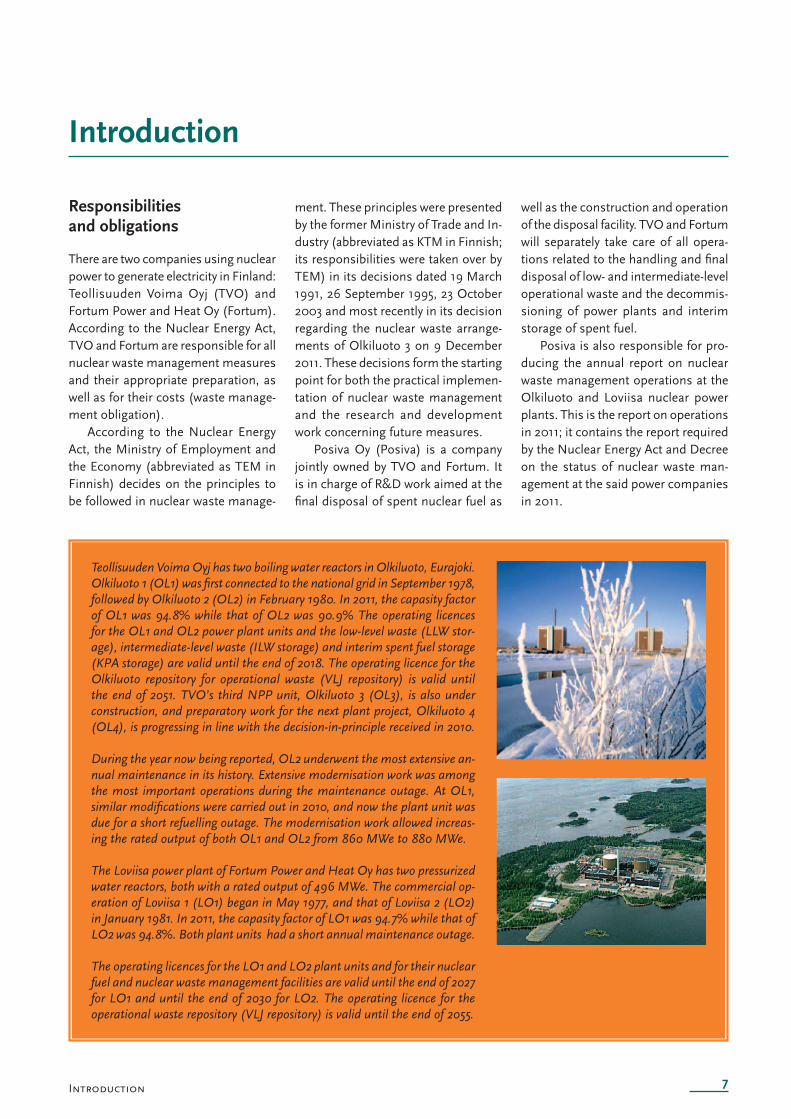
Teollisuuden Voima Oyj has two boiling water reactors in Olkiluoto, Eurajoki. Olkiluoto 1 (OL1) was fi rst connected to the national grid in September 1978, followed by Olkiluoto 2 (OL2) in February 1980. In 2011, the capasity factor of OL1 was 94.8% while that of OL2 was 90.9% The operating licences for the OL1 and OL2 power plant units and the low-level waste (LLW stor-age), intermediate-level waste (ILW storage) and interim spent fuel storage (KPA storage) are valid until the end of 2018. The operating licence for the Olkiluoto repository for operational waste (VLJ repository) is valid until the end of 2051. TVO’s third NPP unit, Olkiluoto 3 (OL3), is also under construction, and preparatory work for the next plant project, Olkiluoto 4 (OL4), is progressing in line with the decision-in-principle received in 2010.
During the year now being reported, OL2 underwent the most extensive an-nual maintenance in its history. Extensive modernisation work was among the most important operations during the maintenance outage. At OL1, similar modifi cations were carried out in 2010, and now the plant unit was due for a short refuelling outage. The modernisation work allowed increas-ing the rated output of both OL1 and OL2 from 860 MWe to 880 MWe.
The Loviisa power plant of Fortum Power and Heat Oy has two pressurized water reactors, both with a rated output of 496 MWe. The commercial op-eration of Loviisa 1 (LO1) began in May 1977, and that of Loviisa 2 (LO2) in January 1981. In 2011, the capasity factor of LO1 was 94.7% while that of LO2 was 94.8%. Both plant units had a short annual maintenance outage.
The operating licences for the LO1 and LO2 plant units and for their nuclear fuel and nuclear waste management facilities are valid until the end of 2027 for LO1 and until the end of 2030 for LO2. The operating licence for the operational waste repository (VLJ repository) is valid until the end of 2055.
ment. These principles were presented by the former Ministry of Trade and In-dustry (abbreviated as KTM in Finnish; its responsibilities were taken over by TEM) in its decisions dated 19 March 1991, 26 September 1995, 23 October 2003 and most recently in its decision regarding the nuclear waste arrange-ments of Olkiluoto 3 on 9 December 2011. These decisions form the starting point for both the practical implemen-tation of nuclear waste management and the research and development work concerning future measures.
Posiva Oy (Posiva) is a company jointly owned by TVO and Fortum. It is in charge of R&D work aimed at the fi nal disposal of spent nuclear fuel as
well as the construction and operation of the disposal facility. TVO and Fortum will separately take care of all opera-tions related to the handling and fi nal disposal of low- and intermediate-level operational waste and the decommis-sioning of power plants and interim storage of spent fuel.
Posiva is also responsible for pro-ducing the annual report on nuclear waste management operations at the Olkiluoto and Loviisa nuclear power plants. This is the report on operations in 2011; it contains the report required by the Nuclear Energy Act and Decree on the status of nuclear waste man-agement at the said power companies in 2011.
Introduction
8
Schedules for disposal operations
In compliance with the Nuclear Energy Act and decisions of KTM, prepara-tions are made for disposing of all spent fuel currently held at the Olkiluo-to and Loviisa plants inside the Finnish bedrock. In its decision of 23 October 2003, KTM changed the schedule of preparations for the disposal of spent fuel so that the preliminary reports and plans required for the construction licence for the disposal facility had to be submitted in 2009. The fi nal reports and plans must be available by the end of 2012. The fi nal disposal is scheduled to start in 2020. Before this time, spent fuel is temporarily stored at the power plant sites in water pools.
In December 2000, the Govern-ment made a decision-in-principle regarding Posiva’s application for fi -nal disposal of spent fuel in Olkiluoto, Eurajoki. Parliament ratifi ed the deci-sion almost unanimously in May 2001. The decision-in-principle remains valid until 17 May 2016.
A decision-in-principle was made in 2002 regarding the fi fth NPP unit in Finland (OL3). At the same time, a further decision-in-principle was made regarding the construction of the re-pository in expanded form so that it would also accommodate the spent fuel from the OL3 plant unit currently under construction. The nuclear waste management obligation of the OL3 plant unit only begins when the plant is operational. The same applies to the latest decision-in-principle made in 2010 regarding TVO’s plant unit OL4.
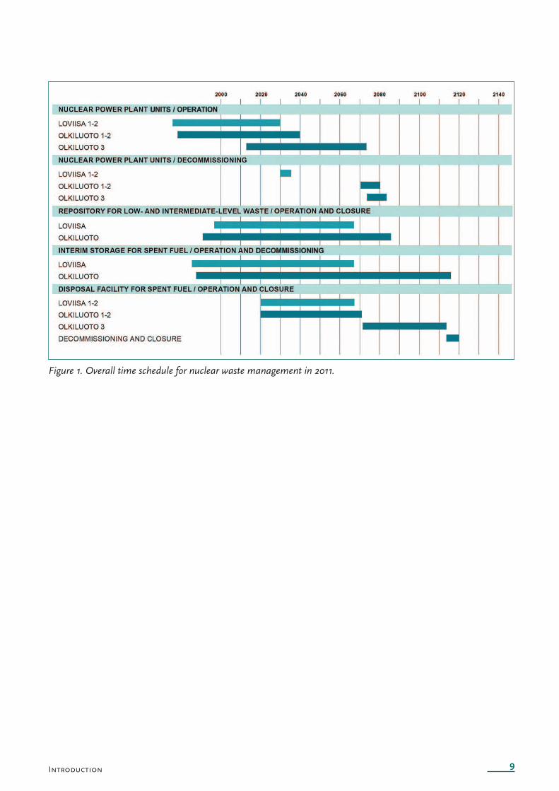
In addition to the report on opera-tions, Posiva also produces an overall programme for nuclear waste manage-ment every three years. The prepara-tions for fi nal disposal of spent nuclear fuel progressed during 2011 in line with the TKS-2009 programme published in September 2009. Figure 1 shows the overall time schedule for nuclear waste management.
Present status of storage operations
The spent fuel from Olkiluoto NPP is temporarily stored in the power plant units and in the interim spent fuel storage (KPA storage) at the power plant site. The KPA storage facility in Olkiluoto can currently accommodate the spent fuel of approximately 30 years worth of production at the OL1 and OL2 units.
The extension project for the spent fuel interim storage in Olkiluoto began in 2009. The site and construction work is scheduled for 2010–2013 so that the extension could be commis-sioned in early 2014. The bases of the extension work are the exhaustio n of storage capacity at the OL1 and OL2 plant units as well as the future needs of OL3. The spent fuel storage exten-sion project increases the pool capacity and is implemented as a normal plant modifi cation of a nuclear facility. Three pools will be constructed in the exten-sion project. The extension of pools should be in operation for the use of OL1 and OL2 plant units in 2014, while the OL3 unit is expected to need its fi rst pool in 2020.The operating li-cence of OL1 and OL2 units has ample capacity for storing the fuel from these units. The permission for extending the capacity and for storing fuel to ac-commodate for the needs of OL3 will be applied for in connection with the operating licence application for OL3.
During the reported year 2011, the 32nd refuelling operation took place at OL1 and the 30th at OL2. At the end of the year, the quantity of spent fuel in storage amounted to a total of 7,670 bundles containing an approximate total of 1,290 tonnes of uranium. Of all the bundles in storage, 6,556 were placed in the KPA storage, 570 in the water pools of OL1 and 544 at OL2. Ad-ditionally, 500 assemblies were in use in the OL1 reactor, with another 500 in use in the OL2 reactor. The fi gures are inclusive of fuel placed in fuel rod racks
(one per plant) used for the storage of damaged fuel rods (a total of 38 rods at the end of 2011).
Spent fuel produced in Loviisa is also stored at the power plant and in the interim spent fuel storages. New spent fuel storage pools were last con-structed at the Loviisa site in 2000. A decision has been made to equip the current pools with high-density racks. This will provide additional capacity until 2020 when the transportation of spent fuel for disposal is expected to start.
In 2007, two new high-density racks were procured for the spent fuel stor-age at Loviisa, and this was repeated in 2009 and 2011. At the end of 2011, the quantity of spent fuel stored at the Loviisa power plant amounted to a to-tal of 4,339 bundles corresponding to an approximate quantity of 522 tonnes of fresh uranium. Of these, 360 as-semblies were stored at LO1 and 293 at LO2. Spent fuel storages 1 and 2 held 480 and 3,206 bundles, respectively. Additionally, 313 assemblies were in use in the LO1 reactor, with another 313 in use in the LO2 reactor.
Co-operation with SKB
Posiva investigates and develops the fi nal disposal concept in cooperation with its Swedish counterpart SKB (Svensk Kärnbränslehantering AB). In 2001, Posiva and SKB signed a fi ve-year cooperation agreement for the purpose of avoiding the duplication of efforts, enhancing the use of resources and promoting the social acceptance of fi -nal disposal. The agreement facilitates implementing joint projects and shar-ing their costs. The good experience from the fi rst fi ve years resulted in the term of the agreement being extended in 2006 by five years and again in 2011 by three years, i.e., until the end of 2014. Since 2001, almost 160 joint projects have been implemented under the agreement.
9
Figure 1. Overall time schedule for nuclear waste management in 2011.
Introduction
10
ONKALO
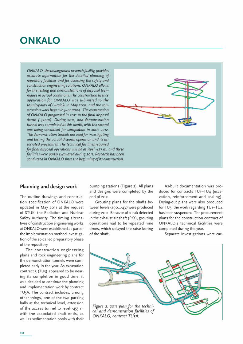
ONKALO, the underground research facility, provides accurate information for the detailed planning of repository facilities and for assessing the safety and construction engineering solutions. ONKALO allows for the testing and demonstrations of disposal tech-niques in actual conditions. The construction licence application for ONKALO was submitted to the Municipality of Eurajoki in May 2003, and the con-struction work began in June 2004 . The construction of ONKALO progressed in 2011 to the fi nal disposal depth (-420m). During 2011, one demonstration tunnel was completed at this depth, with the second one being scheduled for completion in early 2012. The demonstration tunnels are used for investigating and testing the actual disposal operation and its as-sociated procedures. The technical facilities required for fi nal disposal operations will be at level -437 m, and these facilities were partly excavated during 2011. Research has been conducted in ONKALO since the beginning of its construction.
Figure 2. 2011 plan for the techni-cal and demonstration facilities of ONKALO, contract TU5A.
Planning and design work
The outline drawings and construc-tion specifi cation of ONKALO were updated in May 2011 at the request of STUK, the Radiation and Nuclear Safety Authority. The timing alterna-tives of construction engineering works at ONKALO were established as part of the implementation method investiga-tion of the so-called preparatory phase of the repository.
The construction engineering plans and rock engineering plans for the demonstration tunnels were com-pleted early in the year. As excavation contract 5 (TU5) appeared to be near-ing its completion in good time, it was decided to continue the planning and implementation work by contract TU5A. The contract includes, among other things, one of the two parking halls at the technical level, extension of the access tunnel to level -455 m with the associated shaft ends, as well as sedimentation pools with their
pumping stations (Figure 2). All plans and designs were completed by the end of 2011.
Grouting plans for the shafts be-tween levels -290…-437 were produced during 2011. Because of a leak detected in the exhaust air shaft (PK1), grouting operations had to be repeated nine times, which delayed the raise boring of the shaft.
As-built documentation was pro-duced for contracts TU1–TU4 (exca-vation, reinforcement and sealing). Drying-out plans were also produced for TU5; the work regarding TU1–TU4 has been suspended. The procurement plans for the construction contract of ONKALO’s technical facilities were completed during the year.
Separate investigations were car-
11
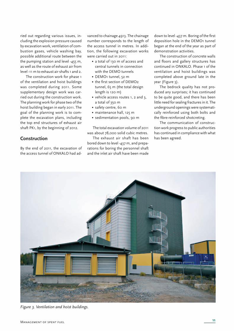
Figure 3. Ventilation and hoist buildings.
Management of spent fuel
ried out regarding various issues, in-cluding the explosion pressure caused by excavation work, ventilation of com-bustion gases, vehicle washing bay, possible additional route between the the pumping station and level -455 m, as well as the route of exhaust air from level -11 m to exhaust air shafts 1 and 2.
The construction work for phase 1 of the ventilation and hoist buildings was completed during 2011. Some supplementary design work was car-ried out during the construction work. The planning work for phase two of the hoist building began in early 2011. The goal of the planning work is to com-plete the excavation plans, including the top end structures of exhaust air shaft PK1, by the beginning of 2012.
Construction
By the end of 2011, the excavation of the access tunnel of ONKALO had ad-
vanced to chainage 4913. The chainage number corresponds to the length of the access tunnel in metres. In addi-tion, the following excavation works were carried out in 2011:
• a total of 130 m of access and central tunnels in connection with the DEMO tunnels• DEMO1 tunnel, 52 m • the fi rst section of DEMO2 tunnel, 65 m (the total design length is 120 m)• vehicle access routes 1, 2 and 3, a total of 350 m• safety centre , 60 m• maintenance hall, 125 m• sedimentation pools, 90 m
The total excavation volume of 2011 was about 78,000 solid cubic metres.
The exhaust air shaft has been bored down to level -437 m, and prepa-rations for boring the personnel shaft and the inlet air shaft have been made
down to level -437 m. Boring of the fi rst deposition hole in the DEMO1 tunnel began at the end of the year as part of demonstration activities.
The construction of concrete walls and fl oors and gallery structures has continued in ONKALO. Phase 1 of the ventilation and hoist buildings was completed above ground late in the year (Figure 3).
The bedrock quality has not pro-duced any surprises; it has continued to be quite good, and there has been little need for sealing fractures in it. The underground openings were systemati-cally reinforced using both bolts and the fi bre-reinforced shotcreting.
The communication of construc-tion work progress to public authorities has continued in compliance with what has been agreed.
12
Characteristics and suitability of the repository site
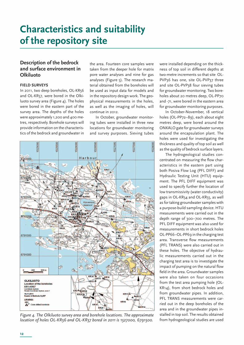
Figure 4. The Olkiluoto survey area and borehole locations. The approximate location of holes OL-KR56 and OL-KR57 bored in 2011 is 1527000, 6791500.
Description of the bedrock and surface environment in Olkiluoto
FIELD SURVEYSIn 2011, two deep boreholes, OL-KR56 and OL-KR57, were bored in the Olki-luoto survey area (Figure 4). The holes were bored in the eastern part of the survey area. The depths of the holes were approximately 1,200 and 400 me-tres, respectively. Borehole surveys will provide information on the characteris-tics of the bedrock and groundwater in
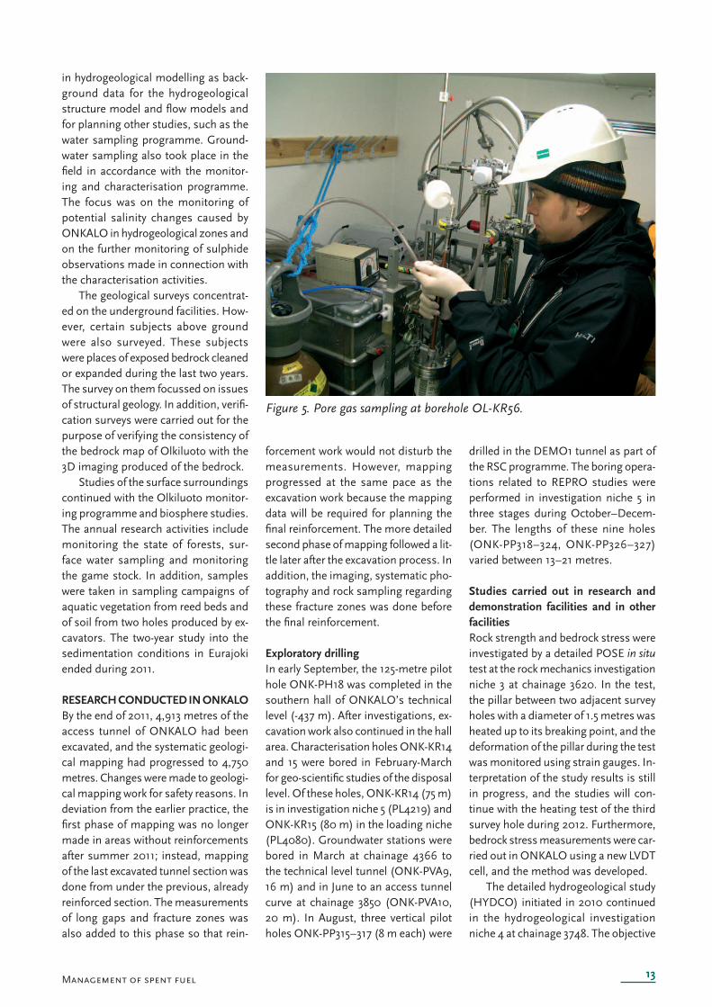
the area. Fourteen core samples were taken from the deeper hole for matrix pore water analyses and nine for gas analyses (Figure 5). The research ma-terial obtained from the boreholes will be used as input data for models and in the repository design work. The geo-physical measurements in the holes, as well as the imaging of holes, will continue in 2012.
In October, groundwater monitor-ing tubes were installed in three new locations for groundwater monitoring and survey purposes. Sieving tubes
were installed depending on the thick-ness of top soil in different depths at two-metre increments so that site OL-PVP36 has one, site OL-PVP37 three and site OL-PVP38 four sieving tubes for groundwater monitoring. Two bore-holes about 20 metres deep, OL-PP70 and -71, were bored in the eastern area for groundwater monitoring purposes.
In October-November, 18 vertical holes (OL-PP72–89), each about eight metres deep, were bored around the ONKALO gate for groundwater surveys around the encapsulation plant. The holes were used for investigating the thickness and quality of top soil as well as the quality of bedrock surface layers.
The hydrogeological studies con-centrated on measuring the fl ow char-acteristics in the eastern part using both Posiva Flow Log (PFL DIFF) and Hydraulic Testing Unit (HTU) equip-ment. The PFL DIFF equipment was used to specify further the location of low transmissivity (water conductivity) gaps in OL-KR54 and OL-KR55, as well as for taking groundwater samples with a purpose-build sampling device. HTU measurements were carried out in the depth range of 300–700 metres. The PFL DIFF equipment was also used for measurements in short bedrock holes OL-PP66–OL-PP69 in the charging test area. Transverse fl ow measurements (PFL TRANS) were also carried out in these holes. The objective of hydrau-lic measurements carried out in the charging test area is to investigate the impact of pumping on the natural fl ow fi eld in the area. Groundwater samples were also taken on four occasions from the test area pumping hole (OL-KR14), from short bedrock holes and from groundwater pipes. In addition, PFL TRANS measurements were car-ried out in the deep boreholes of the area and in the groundwater pipes in-stalled in top soil. The results obtained from hydrogeological studies are used
13
Figure 5. Pore gas sampling at borehole OL-KR56.
Management of spent fuel
in hydrogeological modelling as back-ground data for the hydrogeological structure model and fl ow models and for planning other studies, such as the water sampling programme. Ground-water sampling also took place in the fi eld in accordance with the monitor-ing and characterisation programme. The focus was on the monitoring of potential salinity changes caused by ONKALO in hydrogeological zones and on the further monitoring of sulphide observations made in connection with the characterisation activities.
The geological surveys concentrat-ed on the underground facilities. How-ever, certain subjects above ground were also surveyed. These subjects were places o f exposed bedrock cleaned or expanded during the last two years. The survey on them focussed on issues of structural geology. In addition, verifi -cation s urveys were carried out for the purpose of verifying the consistency of the bedrock map of Olkiluoto with the 3D imaging produced of the bedrock.
Studies of the surface surroundings continued with the Olkiluoto monitor-ing programme and biosphere studies. The annual research activities include monitoring the state of forests, sur-face water sampling and monitoring the game stock. In addition, samples were taken in sampling campaigns of aquatic vegetation from reed beds and of soil from two holes produced by ex-cavators. The two-year study into the sedimentation conditions in Eurajoki ended during 2011.
RESEARCH CONDUCTED IN ONKALOBy the end of 2011, 4,913 metres of the access tunnel of ONKALO had been excavated, and the systematic geologi-cal mapping had progressed to 4,750 metres. Changes were made to geologi-cal mapping work for safety reasons. In deviation from the earlier practice, the fi rst phase of mapping was no longer made in areas without reinforcements after summer 2011; instead, mapping of the last excavated tunnel section was done from under the previous, already reinforced section. The measurements of long gaps and fracture zones was also added to this phase so that rein-
forcement work would not disturb the measurements. However, mapping progressed at the same pace as the excavation work because the mapping data will be required for planning the fi nal reinforcement. The more detailed second phase of mapping followed a lit-tle later after the excavation process. In addition, the imaging, systematic pho-tography and rock sampling regarding these fracture zones was done before the fi nal reinforcement.
Exploratory drillingIn early September, the 125-metre pilot hole ONK-PH18 was completed in the southern hall of ONKALO’s technical level (-437 m). After investigations, ex-cavation work also continued in the hall area. Characterisation holes ONK-KR14 and 15 were bored in February-March for geo-scientifi c studies of the disposal level. Of these holes, ONK-KR14 (75 m) is in investigation niche 5 (PL4219) and ONK-KR15 (80 m) in the loading niche (PL4080). Groundwater stations were bored in March at chainage 4366 to the technical level tunnel (ONK-PVA9, 16 m) and in June to an access tunnel curve at chainage 3850 (ONK-PVA10, 20 m). In August, three vertical pilot holes ONK-PP315–317 (8 m each) were
drilled in the DEMO1 tunnel as part of the RSC programme. The boring opera-tions related to REPRO studies were performed in investigation niche 5 in three stages during October–Decem-ber. The lengths of these nine holes (ONK-PP318–324, ONK-PP326–327) varied between 13–21 metres.
Studies carried out in research and demonstration facilities and in other facilitiesRock strength and bedrock stress were investigated by a detailed POSE in situ test at the rock mechanics investigation niche 3 at chainage 3620. In the test, the pillar between two adjacent survey holes with a diameter of 1.5 metres was heated up to its breaking point, and the deformation of the pillar during the test was monitored using strain gauges. In-terpretation of the study results is still in progress, and the studies will con-tinue with the heating test of the third survey hole during 2012. Furthermore, bedrock stress measurements were car-ried out in ONKALO using a new LVDT cell, and the method was developed.
The detailed hydrogeological study (HYDCO) initiated in 2010 continued in the hydrogeological investigation niche 4 at chainage 3748. The objective
14
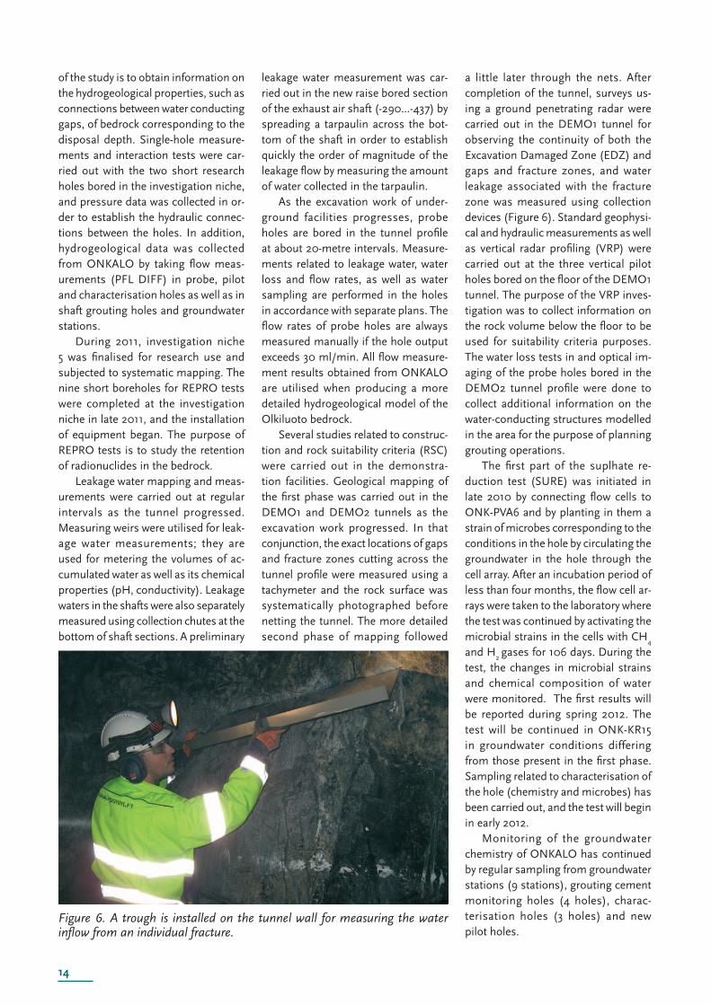
Figure 6. A trough is installed on the tunnel wall for measuring the water infl ow from an individual fracture.
of the study is to obtain information on the hydrogeological properties, such as connections between water conducting gaps, of bedrock corresponding to the disposal depth. Single-hole measure-ments and interaction tests were car-ried out with the two short research holes bored in the investigation niche, and pressure data was collected in or-der to establish the hydraulic connec-tions between the holes. In addition, hydrogeological data was collected from ONKALO by taking fl ow meas-urements (PFL DIFF) in probe, pilot and characterisation holes as well as in shaft grouting holes and groundwater stations.
During 2011, investigation niche 5 was fi nalised for research use and subjected to systematic mapping. The nine short boreholes for REPRO tests were completed at the investigation niche in late 2011, and the installation of equipment began. The purpose of REPRO tests is to study the retention of radionuclides in the bedrock.
Leakage water mapping and meas-urements were carried out at regular intervals as the tunnel progressed. Measuring weirs were utilised for leak-age water measurements; they are used for metering the volumes of ac-cumulated water as well as its chemical properties (pH, conductivity). Leakage waters in the shafts were also separately measured using collection chutes at the bottom of shaft sections. A preliminary
leakage water measurement was car-ried out in the new raise bored section of the exhaust air shaft (-290...-437) by spreading a tarpaulin across the bot-tom of the shaft in order to establish quickly the order of magnitude of the leakage fl ow by measuring the amount of water collected in the tarpaulin.
As the excavation work of under-ground facilities progresses, probe holes are bored in the tunnel profi le at about 20-metre intervals. Measure-ments related to leakage water, water loss and fl ow rates, as well as water sampling are performed in the holes in accordance with separate plans. The fl ow rates of probe holes are always measured manually if the hole output exceeds 30 ml/min. All fl ow measure-ment results obtained from ONKALO are utilised when producing a more detailed hydrogeological model of the Olkiluoto bedrock.
Several studies related to construc-tion and rock suitability criteria (RSC) were carried out in the demonstra-tion facilities. Geological mapping of the fi rst phase was carried out in the DEMO1 and DEMO2 tunnels as the excavation work progressed. In that conjunction, the exact locations of gaps and fracture zones cutting across the tunnel profi le were measured using a tachymeter and the rock surface was systematically photographed before netting the tunnel. The more detailed second phase of mapping followed
a little later through the nets. After completion of the tunnel, surveys us-ing a ground penetrating radar were carried out in the DEMO1 tunnel for observing the continuity of both the Excavation Damaged Zone (EDZ) and gaps and fracture zones, and water leakage associated with the fracture zone was measured using collection devices (Figure 6). Standard geophysi-cal and hydraulic measurements as well as vertical radar profi ling (VRP) were carried out at the three vertical pilot holes bored on the fl oor of the DEMO1 tunnel. The purpose of the VRP inves-tigation was to collect information on the rock volume below the fl oor to be used for suitability criteria purposes. The water loss tests in and optical im-aging of the probe holes bored in the DEMO2 tunnel profi le were done to collect additional information on the water-conducting structures modelled in the area for the purpose of planning grouting operations.
The fi rst part of the suplhate re-duction test (SURE) was initiated in late 2010 by connecting fl ow cells to ONK-PVA6 and by planting in them a strain of microbes corresponding to the conditions in the hole by circulating the groundwater in the hole through the cell array. After an incubation period of less than four months, the fl ow cell ar-rays were taken to the laboratory where the test was continued by activating the microbial strains in the cells with CH
4
and H2 gases for 106 days. During the
test, the changes in microbial strains and chemical composition of water were monitored. The fi rst results will be reported during spring 2012. The test will be continued in ONK-KR15 in groundwater conditions differing from those present in the fi rst phase. Sampling related to characterisation of the hole (chemistry and microbes) has been carried out, and the test will begin in early 2012.
Monitoring of the groundwater chemistry of ONKALO has continued by regular sampling from groundwater stations (9 stations), grouting cement monitoring holes (4 holes), charac-terisation holes (3 holes) and new pilot holes.
15Management of spent fuel
MODELLINGDuring 2011, preparations were made for Olkiluoto Site Description 2011, a report that integrates and compiles the description of the site in one docu-ment. This is version number four of the Olkiluoto Site Description. The geo-scientifi c modelling work of the Olkiluoto survey area is coordinated by the Olkiluoto Modelling Task Force (OMTF). The purpose of the work performed by OMTF is to produce a geological, hydrogeological, geochemi-cal and rock-mechanical description of Olkiluoto. Each fi eld of research has its own modelling team working un-der the OMTF. During 2011 and when the site description report was being completed, the work of the Modelling Task Force concentrated on producing the background reports for the Safety Case and on investigating individual open questions.
Geological and geophysical modellingVersion 2.1 of the geological model of Olkiluoto was completed in 2011 as part of the Olkiluoto Site Description. The 3D image of bedrock was further updat-ed to version 2.2 with respect to brittle fracture zones and rock types, but this update was not separately reported.
The update of the geological model primarily consisted of changes made on the basis of new material and interpre-tations. The 3D images of the rock type model and ductile deformation have in the current version been developed to be consistent with the bedrock map using examination trenches, mapping operations and boring operations. There is now a better understanding on the history of ductile deformation and the chemical and mineralogical changes that have taken place in the rock, and they have been more com-prehensively reported. Understanding of the history of ductile deformation has become more detailed when the deformation zones have been studied. The geological fracture network model was updated to version 2.0, but the cor-responding report was not completed by the end of 2011.
In 2011, the geological modelling work also included so-called small-
scale modelling carried out in the dem-onstration facilities of ONKALO mainly for the purposes of Rock Suitability Criteria (RSC). Small-scale modelling has concentrated on characteristics signifi cant for rock suitability, such as extensive and water-conducting fac-tures and fracture zones whose location and status has been described as ex-tensively as possible near the facilities being built. The model and the suitabil-ity assessment of facilities based on it were updated on several occasions in connection with constructing the dem-onstration facilities and carrying out studies. The latest update was made on the basis of the results from studies in the pilot holes bored on the fl oor of the DEMO1 tunnel. Comprehensive re-porting on the modelling methods and results is scheduled for 2013.
Hydrogeological modellingThe work for updating the hydrogeo-logical structure model initiated in 2010 was completed in early 2011 and later published as a working report. When updating the structural model, the up-date of the geological model (version 2) and research data from the survey hole bored after the previous model update were taken into account in addition to the further accumulated monitoring material from Olkiluoto. The results of this work were immediately utilised for the modelling of Olkiluoto based on gap networks that was also completed during 2011 and for which a report will be published in early 2012. Flow modelling included the modelling of bedrock structure with few cracks, a description of hydraulic conductivity and migration properties using statisti-cal methods as well as a description of the hydrogeological developments in Olkiluoto during the last 8,000 years. The hydrogeological site model of Olki-luoto is also an important basis for the Safety Case to be completed by the end of 2012. Modelling of the migration of radionuclides and of the long-term hydrological developments were also initiated during 2011 for the Safety Case.
In 2011, surface hydrogeological modelling in Olkiluoto concentrated on assessing the impacts of ONKALO,
on producing short-term forecasts and on modelling the impacts of the recharge test. In addition, the model was developed in other ways during the year, including the addition of the salin-ity parameter which will help produce more detailed assessments of leakage waters in ONKALO and in utilising the model for producing limit values for leakage water.
Hydro-geochemical modellingThe hydro-geochemical research ac-tivities in 2011 included preparations of the hydro-geochemical modelling part of Olkiluoto Site Description 2011. The model describes the past hydro-geochemical developments, origin and retention of groundwater types, distribution of salinity, chemical buff-ering capacity of the groundwater sys-tem and changes in the groundwater conditions caused by ONKALO. The paleo-hydro-geochemical model is also used for studying the fl ow behaviour of groundwater as a result of past environ-mental changes. Flow simulations were carried out to support the model. They were used for investigating the diffu-sion between groundwater in bedrock gaps and matrix pore water in rocks, the development of salinity and interac-tion times. The salinity model describes the current distribution of salinity in groundwater in the bedrock fracture net-work. The model is based on, besides the samples taken from groundwater, electrical conductivity measurements of groundwater in individual fractures, taken from boreholes, that are used for calculating the total salinity of water. A summary report on the microbiological conditions of groundwater in Olkiluoto was completed. Its results are part of the hydro-geochemical model and de-scribe oxidation-reduction processes in particular. The recharge test results have been simulated by means of reactive transport modelling. The calculation re-sults and the results from groundwater monitoring are used for assessing, in the Site Report, the buffering capacity of the hydro-geochemical system to neu-tralise the infi ltrating groundwater and maintain reductive chemical conditions.
16
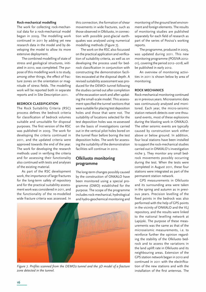
Figure 7. Profi les scanned from the DEMO2 tunnel and the 3D model of a fracture zone detected in the tunnel.
Rock-mechanical modellingThe work for collecting rock-mechan-ical data for a rock-mechanical model began in 2009. The modelling work continued in 2011 by adding yet new research data in the model and by de-veloping the model to allow its more extensive deployment.
The combined modelling of state of stress and geological structures, initi-ated in 2010, was completed. The pur-pose of this modelling work is to study, among other things, the effect of frac-ture zones on the orientation or mag-nitude of stress fi elds. The modelling work will be reported both in separate reports and in Site Description 2011.
BEDROCK CLASSIFICATIONThe Rock Suitability Criteria (RSC) process defi nes the bedrock criteria for classifi cation of bedrock volumes suitable and unsuitable for disposal purposes. The fi rst version of the RSC was published in 2009. The work for developing the criteria continued in 2011, and the updated criteria were approved towards the end of the year. The work for developing the research methods used in verifying the criteria and for assessing their functionality also continued with tests and analyses of the existing material.
As part of the RSC development work, the importance of large fractures for the long-term safety of repository and for the practical suitability assess-ment work was considered in 2011, and the functionality of the re-modelled wide fracture criteria was assessed. In
this connection, the formation of shear movements in wide fractures, such as those observed in Olkiluoto, in connec-tion with possible post-glacial earth-quakes was analysed using numerical modelling methods (Figure 7).
The work on the RSC also focussed on the practical application and verifi ca-tion of suitability criteria, as well as on developing the process used for bed-rock classifi cation in conjunction with constructing the demonstration facili-ties excavated at the disposal depth. A revised suitability assessment was pro-duced for the DEMO1 tunnel following the studies carried out after completion of the excavation work and after updat-ing the small-scale model. This assess-ment specifi ed the tunnel sections that were suitable for placing test deposition holes and those that were not. The suitability of locations selected for the test deposition holes was re-assessed on the basis of investigations carried out in the vertical pilot holes bored on the tunnel fl oor before boring the test deposition holes. The work for assess-ing the suitability of the demonstration facilities will continue in 2012.
Olkiluoto monitoring programme
The long-term changes possibly caused by the construction of ONKALO have been moni tored using a special pro-gramme (OMO) established for the purpose. The scope of the programme includes rock-mechanical, hydrological and hydro-geochemical monitoring and
monitoring of the ground level environ-ment and foreign elements. The results of monitoring studies are published separately for each fi eld of research as part of the series of Posiva’s working reports.
The programme, produced in 2003, was updated during 2011. This new monitoring programme (POSIVA 2012-01), covering the period 2012–2018, will be published in early 2012.
An overview of monitoring activi-ties in 2011 is shown below by area of monitoring.
ROCK MECHANICSRock-mechanical monitoring continued as in previous years. Microseismic data was continuously analysed and moni-tored. Each year, the micro-seismic station network detects over one thou-sand events, most of these explosions during the blasting work in ONKALO. The other seismic events are typically caused by construction work either above or below ground. In addition, four local stations have been installed to support the rock-mechanical studies carried out in ONKALO’s investigation niche 3. They monitor any small bed-rock movements possibly occurring during the test. When the tests were completed in August 2011, these four stations were integrated as part of the permanent station network.
GPS measurements in Olkiluoto and its surrounding area were taken in the spring and autumn as in previ-ous years. Precision levelling of the fi xed points in the bedrock was also performed with the help of GPS points in the vicinity of ONKALO and the VLJ repository, and the results were linked to the national levelling network at Lapijoki. The purpose of these meas-urements was the same as that of the microseismic measurements, i.e. to reinforce further the opinion regard-ing the stability of the Olkiluoto bed-rock and to assess the variations in the land uplift rate in Olkiluoto and its neighbouring areas. Extension of the GPS station network began in 2010 and continued in 2011 with the electrifi ca-tion of the new stations and with the installation of the fi rst antennas. The
17Management of spent fuel
development work will both expand the observation area and improve the accuracy of observations.
Two extensometers were installed in the technical facilities of ONKALO, in the pillars of two halls of east-west orientation in autumn 2011. They are used to monitor the deformation of the pillars during excavation work in the adjacent hall. The forecast and actual dislocations have been of the order of 1–2 millimetres. The extensometer readings will continue to be taken.
HYDROLOGYHydrological monitoring continued in 2011 mainly following the same programme as in 2010. The biggest change from previous years was the change of focus from monitoring the fl ow conditions in boreholes to moni-toring pressures.
Groundwater level observations were made in both shallow groundwater tubes and boreholes and in deep open boreholes using manual methods once a month. A few water level reference holes and short holes in the recharge test area are now also being monitored using automatic level sensors (observa-tions once per hour). The monitoring of pressure heads took place using an automatic pressure monitoring net-work of multiple-plugged boreholes (GWMS). The supply of data by e-mail was switched at the end of 2010 to sup-plying raw data via the POTTI system. The online monitoring of data worked as planned, and the processing and analysis of data was further developed. At the beginning of 2012, corrections for tide and pressure will be introduced in addition to the correction for natural conditions (groundwater and sea level) made to observations in level decrease determinations.
By the end of the year, a total of 25 deep boreholes had been fi tted with multiple plugs and connected to the monitoring network. During 2011, the plugging of hole OL-KR44 was fi nal-ised, the plugging of hole OL-KR28 was repaired and hole OL-KR39 was plugged. The major water-conducting HZ20 structures were penetrated by the ONKALO access tunnel at the turn
of 2008–2009. During 2009–2011, the same structures have often been penetrated by grouting holes in the shafts. In addition, exhaust air shaft ONK-KU2 was raise bored between the depths -290...-437 in October 2011. As in previous years, the impacts of structure penetration-related leaks on groundwater pressure were monitored and analysed during 2011.
A quarterly memorandum on hydro-logical measurements was compiled during the year, discussing the results of level and pressure head measure-ments and analysing the short-term impacts of other field events and ONKALO construction work on pres-sure heads. These results will be re-ported in the hydrological monitoring report to be published in 2012.
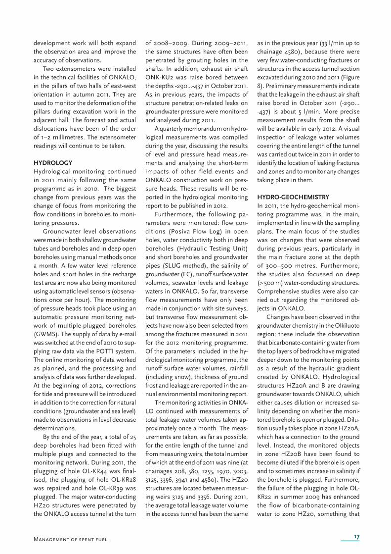
Furthermore, the following pa-rameters were monitored: fl ow con-ditions (Posiva Flow Log) in open holes, water conductivity both in deep boreholes (Hydraulic Testing Unit) and short boreholes and groundwater pipes (SLUG method), the salinity of groundwater (EC), runoff surface water volumes, seawater levels and leakage waters in ONKALO. So far, transverse flow measurements have only been made in conjunction with site surveys, but transverse fl ow measurement ob-jects have now also been selected from among the fractures measured in 2011 for the 2012 monitoring programme. Of the parameters included in the hy-drological monitoring programme, the runoff surface water volumes, rainfall (including snow), thickness of ground frost and leakage are reported in the an-nual environmental monitoring report.
The monitoring activities in ONKA-LO continued with measurements of total leakage water volumes taken ap-proximately once a month. The meas-urements are taken, as far as possible, for the entire length of the tunnel and from measuring weirs, the total number of which at the end of 2011 was nine (at chainages 208, 580, 1255, 1970, 3003, 3125, 3356, 3941 and 4580). The HZ20 structures are located between measur-ing weirs 3125 and 3356. During 2011, the average total leakage water volume in the access tunnel has been the same
as in the previous year (33 l/min up to chainage 4580), because there were very few water-conducting fractures or structures in the access tunnel section excavated during 2010 and 2011 (Figure 8). Preliminary measurements indicate that the leakage in the exhaust air shaft raise bored in October 2011 (-290...-437) is about 5 l/min. More precise measurement results from the shaft will be available in early 2012. A visual inspection of leakage water volumes covering the entire length of the tunnel was carried out twice in 2011 in order to identify the location of leaking fractures and zones and to monitor any changes taking place in them.
HYDRO-GEOCHEMISTRYIn 2011, the hydro-geochemical moni-toring programme was, in the main, implemented in line with the sampling plans. The main focus of the studies was on changes that were observed during previous years, particularly in the main fracture zone at the depth of 300–500 metres. Furthermore, the studies also focussed on deep (> 500 m) water-conducting stru ctures. Comprehensive studies were also car-ried out regarding the monitored ob-jects in ONKALO.
Changes have been observed in the groundwater chemistry in the Olkiluoto region; these include the observation that bicarbonate-containing water from the top layers of bedrock have migrated deeper down to the monitoring points as a result of the hydraulic gradient created by ONKALO. Hydrological structures HZ20A and B are drawing groundwater towards ONKALO, which either causes dilution or increased sa-linity depending on whether the moni-tored borehole is open or plugged. Dilu-tion usually takes place in zone HZ20A, which has a connection to the ground level. Instead, the monitored objects in zone HZ20B have been found to become diluted if the borehole is open and to sometimes increase in salinity if the borehole is plugged. Furthermore, the failure of the plugging in hole OL-KR22 in summer 2009 has enhanced the flow of bicarbonate-containing water to zone HZ20, something that
18
Figure 8. Result of leakage water meas-urement on 6 November 2011, 31.5 l/min up to ONKALO chainage 4580.
was only detected in sampling during 2010 and 2011. The failure of the plug-ging has resulted in the clear dilution of structures HZ20A and B in hole OL-KR22, and it has also possibly contrib-uted to the minor decrease in salinity of structure HZ20A observed in holes OL-KR25 and OL-KR27. Dilution has also been observed in connection with HZ19 structures (in borehole OL-KR37). However, the observation has been made in the monitoring objects of the HZ21 structure that the high hydraulic gradient caused by ONKALO has not yet had any marked effect on deep sa-line groundwaters.
The diluting effect of the Korvensuo reservoir on groundwater has been observed in particular in groundwater pipes and rock holes in its vicinity. Groundwater samples have been taken in ONKALO according to the pro-gramme, primarily from groundwater stations. Nine groundwater stations were regularly monitored during 2011. Both groundwater chemistry studies and microbiological studies have been conducted in these holes, and the results have corresponded very well with the natural state of groundwater with only a few exceptions. Of these exceptions, the increasing sulphate content that was detected during 2011 in sampling from a groundwater sta-tion (ONK-PVA9) located at the dis-posal depth might be mentioned. This change is probably also caused by the hydraulic gradient created by ONKALO.
The studies on the immediate im-
pacts of ONKALO construction work continued with water sampling from fractures and fracture zones leaking water and from waters pumped from ONKALO. The construction of ONKA-LO, in particular concrete spraying, causes from time to time consider-ably high pH values (10–12) in waters pumped from ONKALO. However, the values rapidly decrease in the drain ditch, and no harmful effects on the environment have been observed. The monitoring results will be reported in autumn 2012.
THE ENVIRONMENTThe work of monitoring the ground level environment in Olkiluoto contin-ued in 2011, by and large in line with the planned research programme. The regular research activities include the monitoring of the state of forests in Olkiluoto, a surface water sampling programme and monitoring of game stock through interviews with hunters. In addition, Posiva monitors the envi-ronmental surveys commissioned by TVO and other parties.
In addition to regular studies, sever-al campaign-style studies related to bio-sphere studies were carried out outside the actual monitoring programme. The two-year study into the sedimentation conditions in the Eurajoki Straits ended during the summer, and the results will be published in early 2012. Samples were taken from the shore and aquatic vegetation and sediments in Olkiluoto and in two lakes in Eura and Eurajoki
on three occasions at different stages of the growth season during the year. The work for supplementing the data on swamp areas outside Olkiluoto, initiated in 2010, was continued with the vegetation and peat studies carried out in the Pesänsuo swamp in Mellilä. Two test trenches were excavated as part of the soil studies, and they were used for mapping the layer structure of soil and for taking laboratory samples. Posiva also participated in the nation-wide archipelago birdlife monitoring programme on small islets and islands far out on the Olkiluoto sea area.
FOREIGN MATERIALSThe monitoring and control of foreign materials is part of Posiva’s monitoring programme. Foreign materials refer to all those materials and substances used for constructing ONKALO that are not part of the disposal system. In 2011, a total of 51 applications related to foreign materials or proposals for changing their earlier area of application were processed. The use of each foreign material is described in a separate docu-ment that has a safety data sheet and instructions for use of the subject ma-terial appended to it. The details have been recorded in the materials manual.
During 2011, the quantities of con-struction materials used were moni-tored in compliance with the agreed practice. The records submitted by con-tractors allow calculating the usage of cement both for grouting and for shot-creting. The quantities of explosives, paints and different metal bolts used in construction work are also monitored.
Development work on the methods used for analysing explosive residuals left on the rock surfaces of ONKALO after excavation work began in 2011 us-ing two techniques. Likewise, the solu-bility study of the Densiphalt cladding intended for paving the access route of ONKALO was initiated with the inten-tion of producing more information on any factors possibly affecting the long-term safety of the material.
19
Plant design
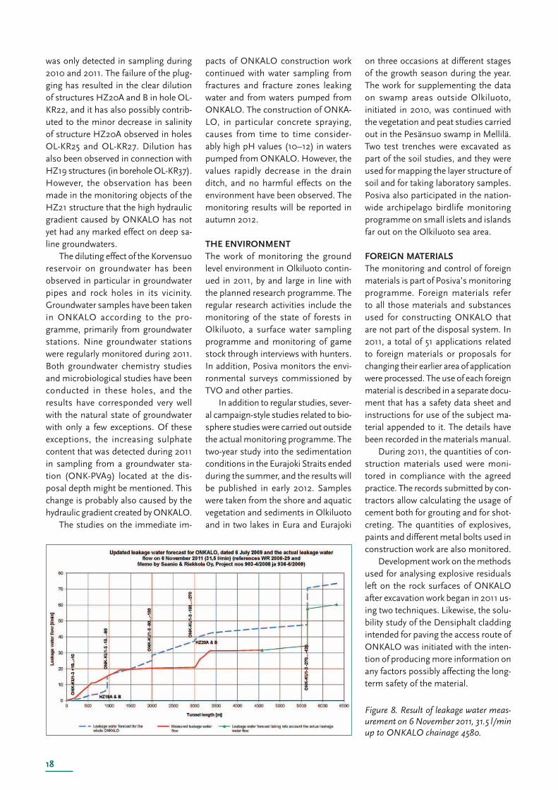
The disposal facility complex consists of an encapsulation plant to be constructed at ground level, other auxiliary build-ings and structures at ground level and the underground repository. The construction work for the encapsulation plant and repository will begin when the construction licence has been granted. The operations of the facility are scheduled to start approximately in 2020 after the operating licence has been granted.
The spent fuel brought from the interim storage is packaged into canisters in the encapsulation plant and transferred to
the repository in a lift. The current plans involve excavation of the repository facilities on one level at -420 m. Access to the underground facilities is through the access tunnel and shafts. Deposition holes will be bored in the fl oors of the deposition tunnels for inserting the canisters. The canisters will be completely surrounded by bentonite blocks that will swell considerably when becoming wet. The facilities will be expanded as the disposal operations progress by excavation of more deposition and central tunnels. The planning and design work for the encapsulation plant and repository progresses in three-year periods.
Management of spent fuel
Encapsulation plant
In 2011, the encapsulation design work involved the continued preparation of documentation for the construction licence application. When preparing the application documentation and in particular the system descriptions to be submitted to the authorities with the application, Posiva has sought to take into account the further specifi ed requirements of the YVL Guides cur-rently being updated by STUK to the extent that they are already known.
In the systems design work for the
encapsulation plant, the updating work for the preliminary plans regarding the fuel handling cell was initiated; the most important update concerns the plan for the fuel transfer mechanism. At the same time, the systematic work for determining the requirements con-cerning the transfer mechanism was initiated with a view to supporting the detailed design and procurement of the mechanism in the future. In addition, the work for updating the plan for the automatic guided vehicle for canisters was begun. The automatic guided ve-hicle will be used for transferring the
canisters to the canister lift at the en-capsulation plant and from the lift at the repository depth. Preliminary plans for the canister lift were also produced for preparation of the licensing docu-mentation.
Plan updates for the ventilation, cooling and electrical systems of the encapsulation plant were also initiated, taking into account the verifi cation re-quirements related to safety functions.
Copper machining tests were per-formed in order to fi nd the suitable tools and machining methods for the copper machining station of the encap-
20
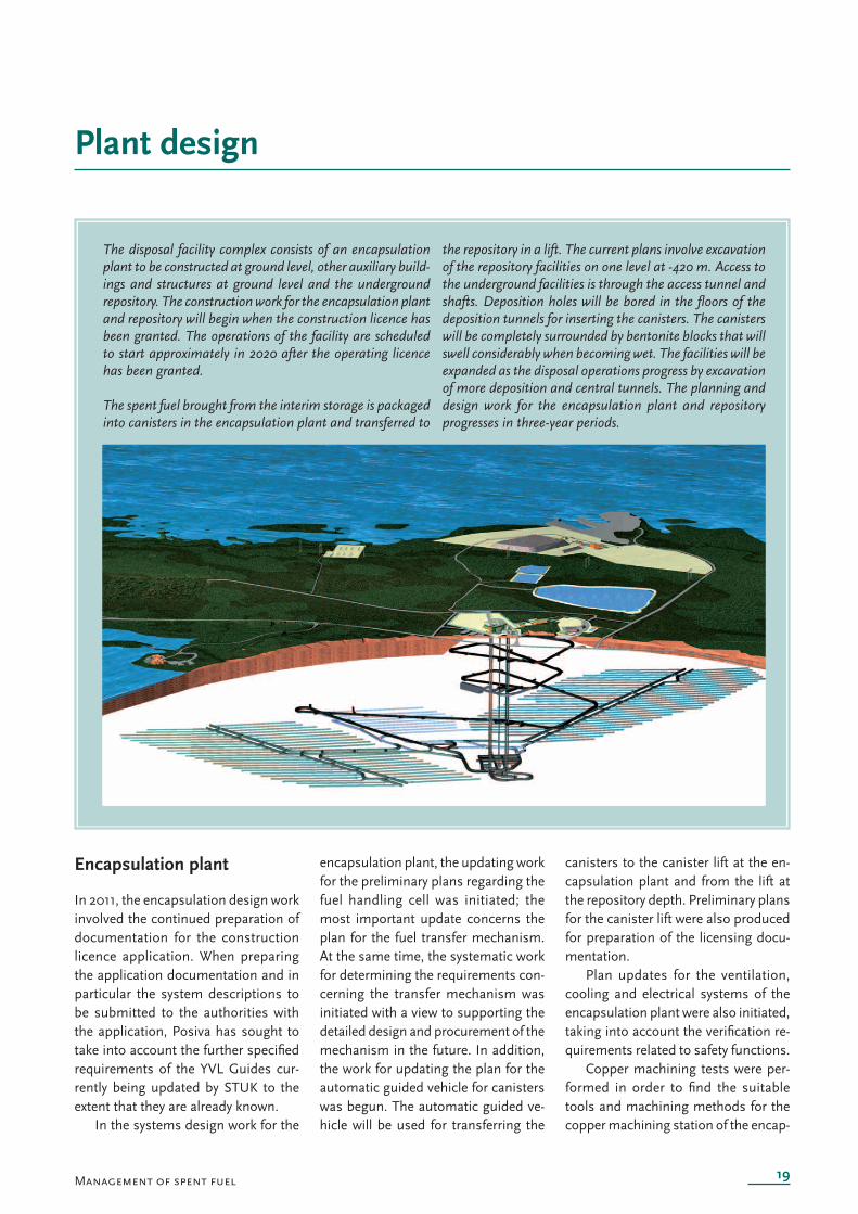
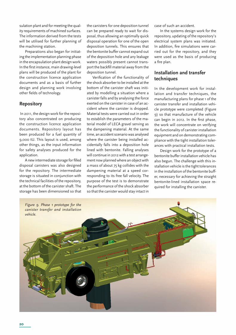
Figure 9. Phase 1 prototype for the canister transfer and installation vehicle.
sulation plant and for meeting the qual-ity requirements of machined surfaces. The information derived from the tests will be utilised for further planning of the machining station.
Preparations also began for initiat-ing the implementation planning phase in the encapsulation plant design work. In the fi rst instance, main drawing-level plans will be produced of the plant for the construction licence application documents and as a basis of further design and planning work involving other fi elds of technology.
Repository
In 2011, the design work for the reposi-tory also concentrated on producing the construction licence application documents. Repository layout has been produced for a fuel quantity of 9,000 tU. This layout is used, among other things, as the input information for safety analyses produced for the application.
A new intermediate storage for fi lled disposal canisters was also designed for the repository. The intermediate storage is situated in conjunction with the technical facilities of the repository, at the bottom of the canister shaft. The storage has been dimensioned so that
the canisters for one deposition tunnel can be prepared ready to wait for dis-posal, thus allowing an optimally quick disposal operation for one of the open deposition tunnels. This ensures that the bentonite buffer cannot expand out of the deposition hole and any leakage waters possibly present cannot trans-port the backfi ll material away from the deposition tunnel.
Verifi cation of the functionality of the shock absorber to be installed at the bottom of the canister shaft was initi-ated by modelling a situation where a canister falls and by analysing the force exerted on the canister in case of an ac-cident where the canister is dropped. Material tests were carried out in order to establish the parameters of the ma-terial model of LECA gravel serving as the dampening material. At the same time, an accident scenario was analysed where the canister being installed ac-cidentally falls into a deposition hole lined with bentonite. Falling analyses will continue in 2012 with a test arrange-ment now planned where an object with a mass of about 75 kg collides with the dampening material at a speed cor-responding to its free fall velocity. The purpose of the test is to demonstrate the performance of the shock absorber so that the canister would stay intact in
case of such an accident.In the systems design work for the
repository, updating of the repository’s electrical system plans was initiated. In addition, fi re simulations were car-ried out for the repository, and they were used as the basis of producing a fi re plan.
Installation and transfer techniques
In the development work for instal-lation and transfer techniques, the manufacturing plans for phase 1 of the canister transfer and installation vehi-cle prototype were completed (Figure 9) so that manufacture of the vehicle can begin in 2012. In the fi rst phase, the work will concentrate on verifying the functionality of canister installation equipment and on demonstrating com-pliance with the tight installation toler-ances with practical installation tests.
Design work for the prototype of a bentonite buffer installation vehicle has also begun. The challenge with this in-stallation vehicle is the tight tolerances in the installation of the bentonite buff-er, necessary for achieving the straight bentonite-lined installation space re-quired for installing the canister.
21
Control of nuclear materials and nuclearnonproliferation control
The purpose of nuclear non-prolifer-ation control by Posiva is to ensure compliance with the relevant legisla-tion and international treaties govern-ing the matter during the construction phase of ONKALO.
Posiva has produced a nuclear non-proliferation control manual that describes the nuclear non-proliferation control during the construction phase of ONKALO. The nuclear non-prolifera-tion control manual has been updated as required. Two updates were made in 2011. The manual defi nes the pre-liminary, actual and monitoring data concerning ONKALO t hat is reported three times a year to STUK. In addition, STUK carries out inspections, includ-ing the inspections of the ONKALO’s underground openings and periodic
inspections of the entire nuclear non-proliferation control system. In 2011, STUK performed three periodic inspec-tions of nuclear non-proliferation con-trol measures, one of them as a joint inspection with IAEA and Euratom. No objections concerning ONKALO nuclear non-proliferation control were raised in these inspections.
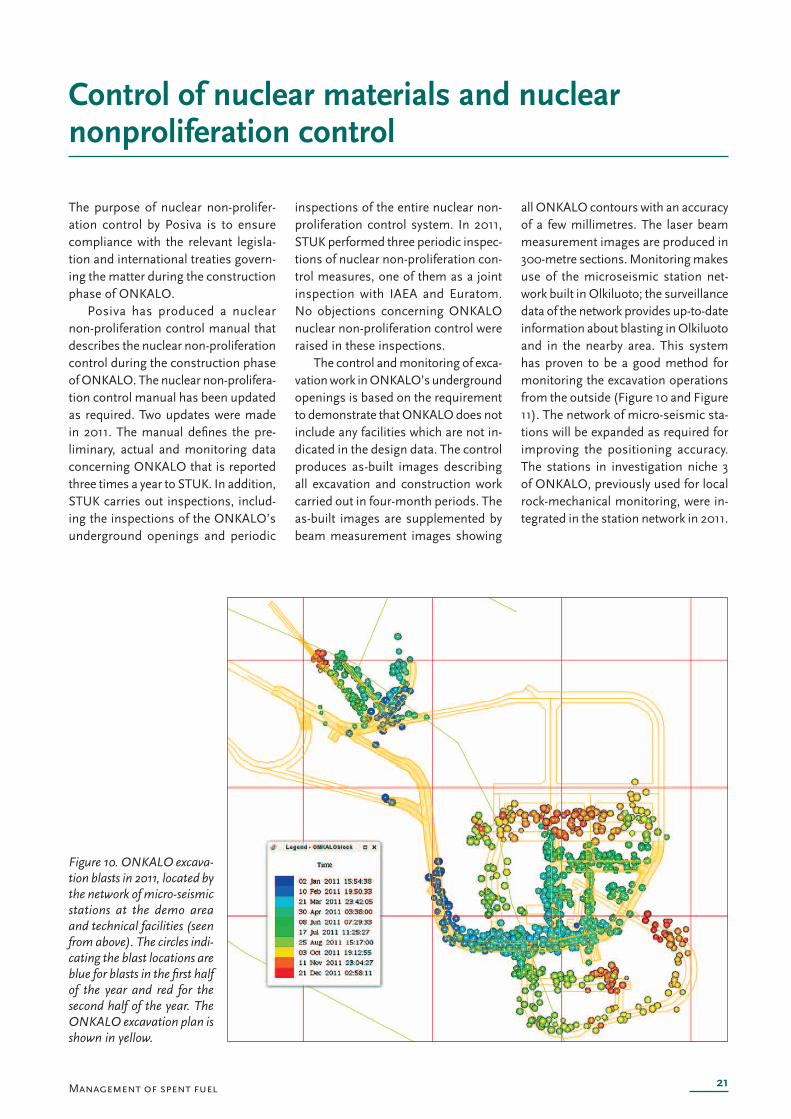
The control and monitoring of exca-vation work in ONKALO’s underground openings is based on the requirement to demonstrate that ONKALO does not include any facilities which are not in-dicated in the design data. The control produces as-built images describing all excavation and construction work carried out in four-month periods. The as-built images are supplemented by beam measurement images showing
all ONKALO contours with an accuracy of a few millimetres. The laser beam measurement images are produced in 300-metre sections. Monitoring makes use of the microseismic station net-work built in Olkiluoto; the surveillance data of the network provides up-to-date information about blasting in Olkiluoto and in the nearby area. This system has proven to be a good method for monitoring the excavation operations from the outside (Figure 10 and Figure 11). The network of micro-seismic sta-tions will be expanded as required for improving the positioning accuracy. The stations in investigation niche 3 of ONKALO, previously used for local rock-mechanical monitoring, were in-tegrated in the station network in 2011.
Figure 10. ONKALO excava-tion blasts in 2011, located by the network of micro-seismic stations at the demo area and technical facilities (seen from above). The circles indi-cating the blast locations are blue for blasts in the fi rst half of the year and red for the second half of the year. The ONKALO excavation plan is shown in yellow.
Management of spent fuel
22
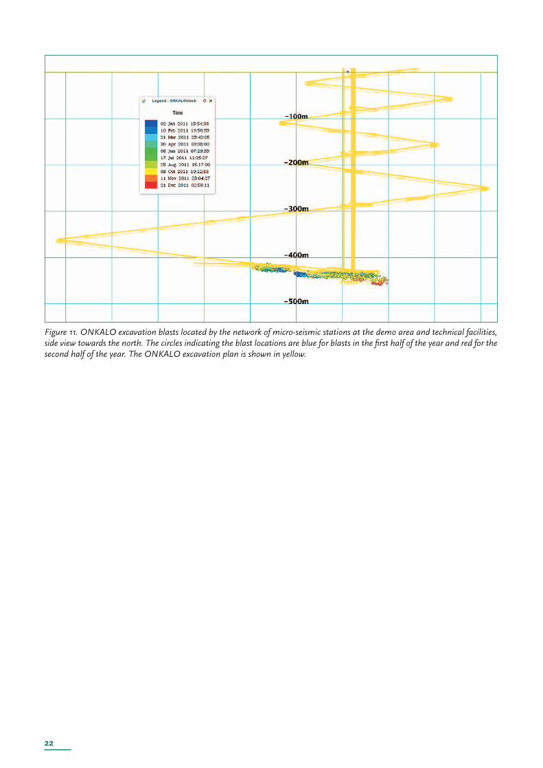
Figure 11. ONKALO excavation blasts located by the network of micro-seismic stations at the demo area and technical facilities, side view towards the north. The circles indicating the blast locations are blue for blasts in the fi rst half of the year and red for the second half of the year. The ONKALO excavation plan is shown in yellow.
23
Disposal system
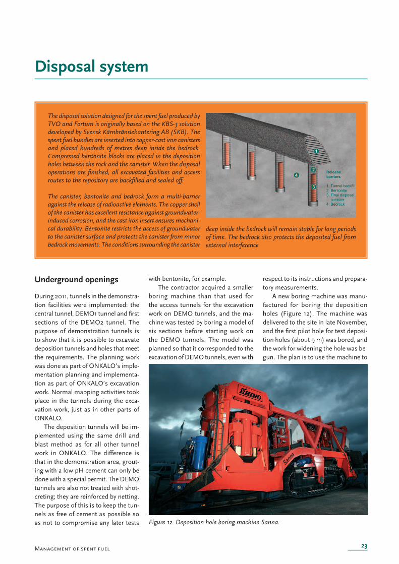
The disposal solution designed for the spent fuel produced by TVO and Fortum is originally based on the KBS-3 solution developed by Svensk Kärnbränslehantering AB (SKB). The spent fuel bundles are inserted into copper-cast iron canisters and placed hundreds of metres deep inside the bedrock. Compressed bentonite blocks are placed in the deposition holes between the rock and the canister. When the disposal operations are fi nished, all excavated facilities and access routes to the repository are backfi lled and sealed off.
The canister, bentonite and bedrock form a multi-barrier against the release of radioactive elements. The copper shell of the canister h as excellent resistance against groundwater-induced corrosion, and the cast iron insert ensures mechani-cal durability. Bentonite restricts the access of groundwater to the canister surface and protects the canister from minor bedrock movements. The conditions surrounding the canister
deep inside the bedrock will remain stable for long periods of time. The bedrock also protects the deposited fuel from external interference
Figure 12. Deposition hole boring machine Sanna.
Management of spent fuel
Underground openings
During 2011, tunnels in the demonstra-tion facilities were implemented: the central tunnel, DEMO1 tunnel and fi rst sections of the DEMO2 tunnel. The purpose of demonstration tunnels is to show that it is possible to excavate deposition tunnels and holes that meet the requirements. The planning work was done as part of ONKALO’s imple-mentation planning and implementa-tion as part of ONKALO’s excavation work. Normal mapping activities took place in the tunnels during the exca-vation work, just as in other parts of ONKALO.
The deposition tunnels will be im-plemented using the same drill and blast method as for all other tunnel work in ONKALO. The difference is that in the demonstration area, grout-ing with a low-pH cement can only be done with a special permit. The DEMO tunnels are also not treated with shot-creting; they are reinforced by netting. The purpose of this is to keep the tun-nels as free of cement as possible so as not to compromise any later tests
with bentonite, for example.The contractor acquired a smaller
boring machine than that used for the access tunnels for the excavation work on DEMO tunnels, and the ma-chine was tested by boring a model of six sections before starting work on the DEMO tunnels. The model was planned so that it corresponded to the excavation of DEMO tunnels, even with
respect to its instructions and prepara-tory measurements.
A new boring machine was manu-factured for boring the deposition holes (Figure 12). The machine was delivered to the site in late November, and the fi rst pilot hole for test deposi-tion holes (about 9 m) was bored, and the work for widening the hole was be-gun. The plan is to use the machine to
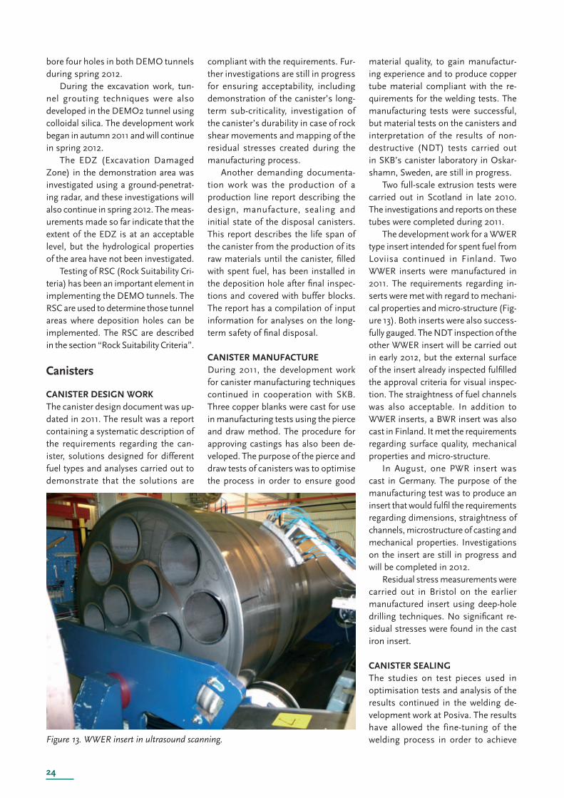
24
F igure 13. WWER insert in ultrasound scanning.
bore four holes in both DEMO tunnels during spring 2012.
During the excavation work, tun-nel grouting techniques were also developed in the DEMO2 tunnel using colloidal silica. The development work began in autumn 2011 and will continue in spring 2012.
The EDZ (Excavation Damaged Zone) in the demonstration area was investigated using a ground-penetrat-ing radar, and these investigations will also continue in spring 2012. The meas-urements made so far indicate that the extent of the EDZ is at an acceptable level, but the hydrological properties of the area have not been investigated.
Testing of RSC (Rock Suitability Cri-teria) has been an important element in implementing the DEMO tunnels. The RSC are used to determine those tunnel areas where deposition holes can be implemented. The RSC are described in the section “Rock Suitability Criteria”.
Canisters
CANISTER DESIGN WORKThe canister design document was up-dated in 2011. The result was a report containing a systematic description of the requirements regarding the can-ister, solutions designed for different fuel types and analyses carried out to demonstrate that the solutions are
compliant with the requirements. Fur-ther investigations are still in progress for ensuring acceptability, including demonstration of the canister’s long-term sub-criticality, investigation o f the canister’s durability in case of rock shear movements and mapping of the residual stresses created during the manufacturing process.
Another demanding documenta-tion work was the production of a production line report describing the design, manufacture, sealing and initial state of the disposal canisters. This report describes the life span of the canister from the production of its raw materials until the canister, fi lled with spent fuel, has been installed in the deposition hole after fi nal inspec-tions and covered with buffer blocks. The report has a compilation of input information for analyses on the long-term safety of fi nal disposal.
CANISTER MANUFACTUREDuring 2011, the development work for canister manufacturing techniques continued in cooperation with SKB. Three copper blanks were cast for use in manufacturing tests using the pierce and draw method. The procedure for approving castings has also been de-veloped. The purpose of the pierce and draw tests of canisters was to optimise the process in order to ensure good
material quality, to gain manufactur-ing experience and to produce copper tube material compliant with the re-quirements for the welding tests. The manufacturing tests were successful, but material tests on the canisters and interpretation of the results of non-destructive (NDT) tests carried out in SKB’s canister laboratory in Oskar-shamn, Sweden, are still in progress.
Two full-scale extrusion tests were carried out in Scotland in late 2010. The investigations and reports on these tubes were completed during 2011.
The development work for a WWER type insert intended for spent fuel from Loviisa continued in Finland. Two WWER inserts were manufactured in 2011. The requirements regarding in-serts were met with regard to mechani-cal properties and micro-structure (Fig-ure 13). Both inserts were also success-fully gauged. The NDT inspection of the other WWER insert will be carried out in early 2012, but the external surface of the insert already inspected fulfi lled the approval criteria for visual inspec-tion. The straightness of fuel channels was also acceptable. In addition to WWER inserts, a BWR insert was also cast in Finland. It met the requirements regarding surface quality, mechanical properties and micro-structure.
In August, one PWR insert was cast in Germany. The purpose of the manufacturing test was to produce an insert that would fulfi l the requirements regarding dimensions, straightness of channels, microstructure of casting and mechanical properties. Investigations on the insert are still in progress and will be completed in 2012.
Residual stress measurements were carried out in Bristol on the earlier manufactured insert using deep-hole drilling techniques. No signifi cant re-sidual stresses were found in the cast iron insert.
CANISTER SEALINGThe studies on test pieces used in optimisation tests and analysis of the results continued in the welding de-velopment work at Posiva. The results have allowed the fine-tuning of the welding process in order to achieve
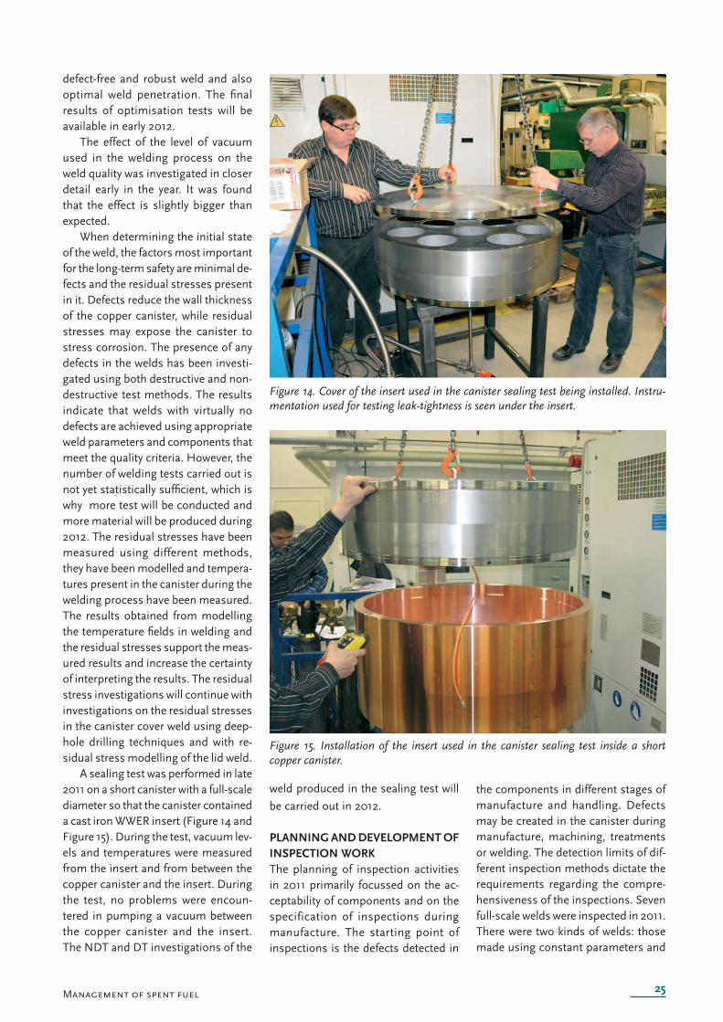
25
Fi gure 14. Cover of the insert used in the canister sealing test being installed. Instru-mentation used for testing leak-tightness is seen under the insert.
Fig ure 15. Installation of the insert used in the canister sealing test inside a short copper canister.
Management of spent fuel
defect-free and robust weld and also optimal weld penetration. The fi nal results of optimisation tests will be available in early 2012.
The effect of the level of vacuum used in the welding process on the weld quality was investigated in closer detail early in the year. It was found that the effect is slightly bigger than expected.
When determining the initial state of the weld, the factors most important for the long-term safety are minimal de-fects and the residual stresses present in it. Defects reduce the wall thickness of the copper canister, while residual stresses may expose the canister to stress corrosion. The presence of any defects in the welds has been investi-gated using both destructive and non-destructive test methods. The results indicate that welds with virtually no defects are achieved using appropriate weld parameters and components that meet the quality criteria. However, the number of welding tests carried out is not yet statistically suffi cient, which is why more test will be conducted and more material will be produced during 2012. The residual stresses have been measured using different methods, they have been modelled and tempera-tures present in the canister during the welding process have been measured. The results obtained from modelling the temperature fi elds in welding and the residual stresses support the meas-ured results and increase the certainty of interpreting the results. The residual stress investigations will continue with investigations on the residual stresses in the canister cover weld using deep-hole drilling techniques and with re-sidual stress modelling of the lid weld.
A sealing test was performed in late 2011 on a short canister with a full-scale diameter so that the canister contained a cast iron WWER insert (Figure 14 and Figure 15). During the test, vacuum lev-els and temperatures were measured from the insert and from between the copper canister and the insert. During the test, no problems were encoun-tered in pumping a vacuum between the copper canister and the insert. The NDT and DT investigations of the
weld produced in the sealing test will
be carried out in 2012.
PLANNING AND DEVELOPMENT OF INSPECTION WORKThe planning of inspection activities in 2011 primarily focussed on the ac-ceptability of components and on the specification of inspections during manufacture. The starting point of inspections is the defects detected in
the components in different stages of manufacture and handling. Defects may be created in the canister during manufacture, machining, treatments or welding. The detection limits of dif-ferent inspection methods dictate the requirements regarding the compre-hensiveness of the inspections. Seven full-scale welds were inspected in 2011. There were two kinds of welds: those made using constant parameters and
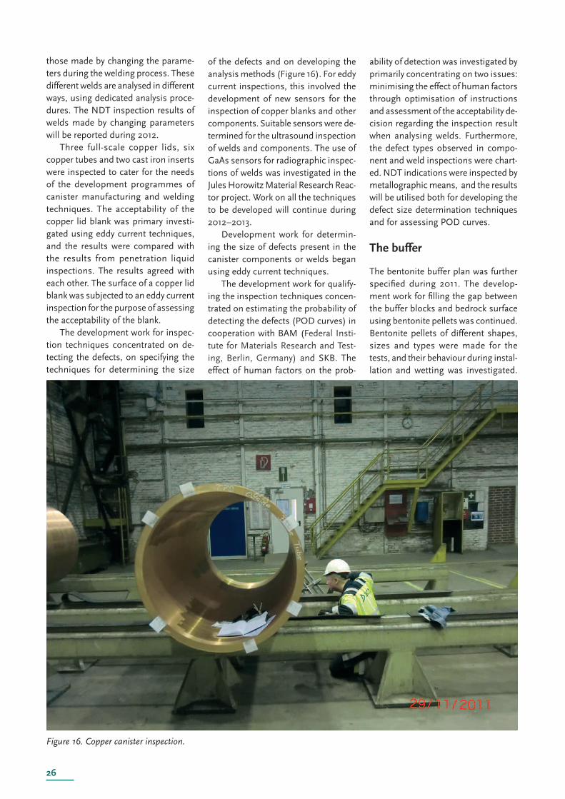
26
Figu re 16. Copper canister inspection.
those made by changing the parame-ters during the welding process. These different welds are analysed in different ways, using dedicated analysis proce-dures. The NDT inspection results of welds made by changing parameters will be reported during 2012.
Three full-scale copper lids, six copper tubes and two cast iron inserts were inspected to cater for the needs of the development programmes of canister manufacturing and welding techniques. The acceptability of the copper lid blank was primary investi-g ated using eddy current techniques, and the results were compared with the results from penetration liquid inspections. The results agreed with each other. The surface of a copper lid blank was subjected to an eddy current inspection for the purpose of assessing the acceptability of the blank.
The development work for inspec-tion techniques concentrated on de-tecting the defects, on specifying the techniques for determining the size
of the defects and on developing the analysis methods (Figure 16). For eddy current inspections, this involved the development of new sensors for the inspection of copper blanks and other components. Suitable sensors were de-termined for the ultrasound inspection of welds and components. The use of GaAs sensors for radiographic inspec-tions of welds was investigated in the Jules Horowitz Material Research Reac-tor project. Work on all the techniques to be developed will continue during 2012–2013.
Development work for determin-ing the size of defects present in the canister components or welds began using eddy current techniques.
The development work for qualify-ing the inspection techniques concen-trated on estimating the probability of detecting the defects (POD curves) in cooperation with BAM (Federal Insti-tute for Materials Research and Test-ing, Berlin, Germany) and SKB. The effect of human factors on the prob-
ability of detection was investigated by primarily concentrating on two issues: minimising the effect of human factors through optimisation of instructions and assessment of the acceptability de-cision regarding the inspection result when analysing welds. Furthermore, the defect types observed in compo-nent and weld inspections were chart-ed. NDT indications were inspected by metallographic means, and the results will be utilised both for developing the defect size determination techniques and for assessing POD curves.
The buffer
The bentonite buffer plan was further specifi ed during 2011. The develop-ment work for fi lling the gap between the buffer blocks and bedrock surface using bentonite pellets was continued. Bentonite pellets of different shapes, sizes and types were made for the tests, and their behaviour during instal-lation and wetting was investigated.
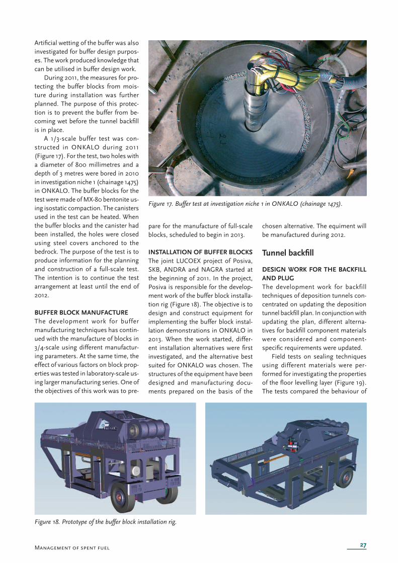
27
Figure 17. Buffer test at investigation niche 1 in ONKALO (chainag e 1475).
Figure 18. Prototype of the buffer block installation rig.
Management of spent fuel
Artifi cial wetting of the buffer was also investigated for buffer design purpos-es. The work produced knowledge that can be utilised in buffer design work.
During 2011, the measures for pro-tecting the buffer blocks from mois-ture during installation was further planned. The purpose of this protec-tion is to prevent the buffer from be-coming wet before the tunnel backfi ll is in place.
A 1/3-scale buffer test was con-structed in ONKALO during 2011 (Figure 17). For the test, two holes with a diameter of 800 millimetres and a depth of 3 metres were bored in 2010 in investigation niche 1 (chainage 1475) in ONKALO. The buffer blocks for the test were made of MX-80 bentonite us-ing isostatic compaction. The canisters used in the test can be heated. When the buffer blocks and the canister had been installed, the holes were closed using steel covers anchored to the bedrock. The purpose of the test is to produce information for the planning and construction of a full-scale test. The intention is to continue the test arrangement at least until the end of 2012.
BUFFER BLOCK MANUFACTUREThe development work for buffer manufacturing techniques has contin-ued with the manufacture of blocks in 3/4-scale using different manufactur-ing parameters. At the same time, the effect of various factors on block prop-erties was tested in laboratory-scale us-ing larger manufacturing series. One of the objectives of this work was to pre-
pare for the manufacture of full-scale blocks, scheduled to begin in 2013.
INSTALLATION OF BUFFER BLOCKSThe joint LUCOEX project of Posiva, SKB, ANDRA and NAGRA started at the beginning of 2011. In the project, Posiva is responsible for the develop-ment work of the buffer block installa-tion rig (Figure 18). The objective is to design and construct equipment for implementing the buffer block instal-lation demonstrations in ONKALO in 2013. When the work started, differ-ent installation alternatives were fi rst investigated, and the alternative best suited for ONKALO was chosen. The structures of the equipment have been designed and manufacturing docu-ments prepared on the basis of the
chosen alternative. The equiment will be manufactured during 2012.
Tunnel backfi ll
DESIGN WORK FOR THE BACKFILL AND PLUGThe development work for backfill techniques of deposition tunnels con-centrated on updating the deposition tunnel backfi ll plan. In conjunction with updating the plan, different alterna-tives for backfi ll component materials were considered and component-specifi c requirements were updated.
Field tests on sealing techniques using different materials were per-formed for investigating the properties of the fl oor levelling layer (Figure 19). The tests compared the behaviour of
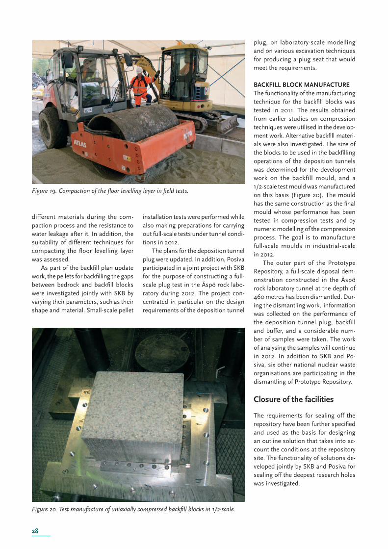
28
Figure 19. Compaction of the fl oor levelling layer in fi eld tests.
Figure 20. Test manufacture of uniaxially compressed backfi ll blocks in 1/2-scale.
different materials during the com-paction process and the resistance to water leakage after it. In addition, the suitability of different techniques for compacting the fl oor levelling layer was assessed.
As part of the backfi ll plan update work, the pellets for backfi lling the gaps between bedrock and backfi ll blocks were investigated jointly with SKB by varying their parameters, such as their shape and material. Small-scale pellet
installation tests were performed while also making preparations for carrying out full-scale tests under tunnel condi-tions in 2012.
The plans for the deposition tunnel plug were updated. In addition, Posiva participated in a joint project with SKB for the purpose of constructing a full-scale plug test in the Äspö rock labo-ratory during 2012. The project con-centrated in particular on the design requirements of the deposition tunnel
plug, on laboratory-scale modelling and on various excavation techniques for producing a plug seat that would meet the requirements.
BACKFILL BLOCK MANUFACTUREThe functionality of the manufacturing technique for the backfi ll blocks was tested in 2011. The results obtained from earlier studies on compression techniques were utilised in the develop-ment work. Alternative backfi ll materi-als were also investigated. The size of the blocks to be used in the backfi lling operations of the deposition tunnels was determined for the development work on the backfill mould, and a 1/2-scale test mould was manufactured on this basis (Figure 20). The mould has the same construction as the fi nal mould whose performance has been tested in compression tests and by numeric modelling of the compression process. The goal is to manufacture full-scale moulds in industrial-scale in 2012.
The outer part of the Prototype Repository, a full-scale disposal dem-onstration constructed in the Äspö rock laboratory tunnel at the depth of 460 metres has been dismantled. Dur-ing the dismantling work, information was collected on the performance of the deposition tunnel plug, backfill and buffer, and a considerable num-ber of samples were taken. The work of analysing the samples will continue in 2012. In addition to SKB and Po-siva, six other national nuclear waste organisations are participating in the dismantling of Prototype Repository.
Closure of the facilities
The requirements for sealing off the repository have been further specifi ed and used as the basis for designing an outline solution that takes into ac-count the conditions at the repository site. The functionality of solutions de-veloped jointly by SKB and Posiva for sealing off the deepest research holes was investigated.
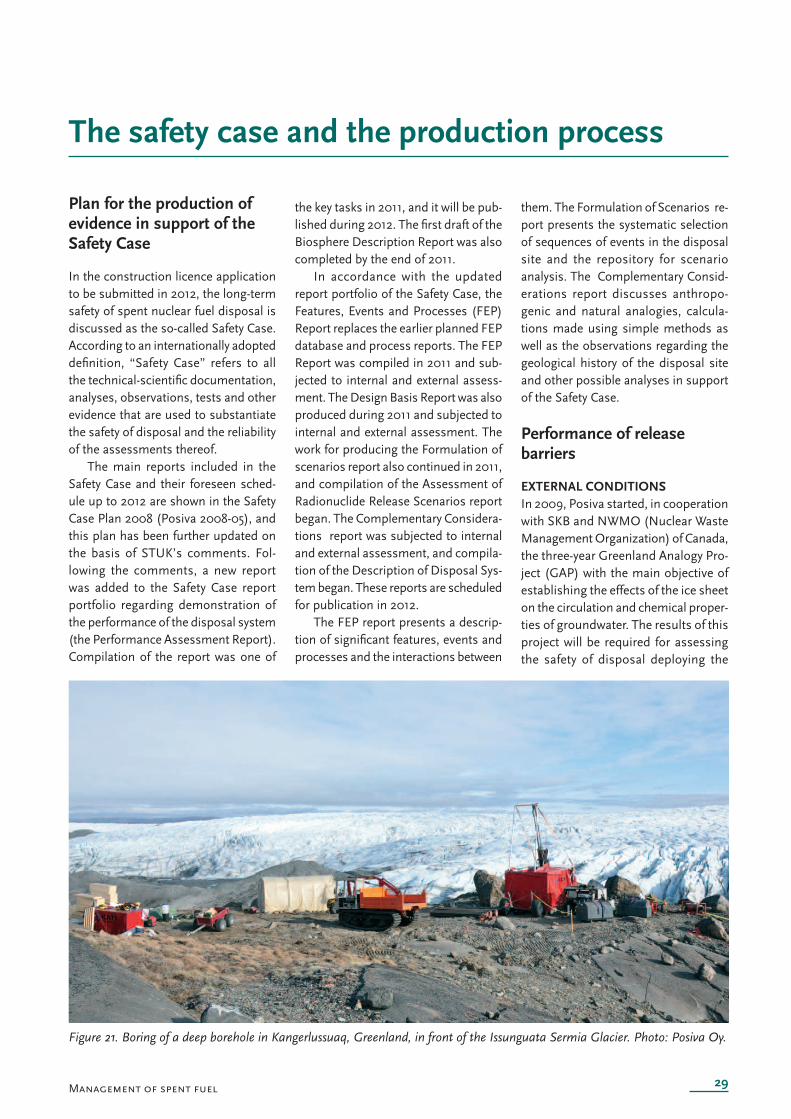
29
The safety case and the production process
Figure 21. Boring of a deep borehole in Kangerlussuaq, Greenland, in front of the Issunguata Sermia Glacier. Photo: Posiva Oy.
Management of spent fuel
Plan for the production of evidence in support of the Safety Case
In the construction licence application to be submitted in 2012, the long-term safety of spent nuclear fuel disposal is discussed as the so-called Safety Case. According to an internationally adopted defi nition, “Safety Case” refers to all the technical-scientifi c documentation, analyses, observations, tests and other evidence that are used to substantiate the safety of disposal and the reliability of the assessments thereof.
The main reports included in the Safety Case and their foreseen sched-ule up to 2012 are shown in the Safety Case Plan 2008 (Posiva 2008-05), and this plan has been further updated on the basis of STUK’s comments. Fol-lowing the comments, a new report was added to the Safety Case report portfolio regarding demonstration of the performance of the disposal system (the Performance Assessment Report). Compilation of the report was one of
the key tasks in 2011, and it will be pub-lished during 2012. The fi rst draft of the Biosphere Description Report was also completed by the end of 2011.
In accordance with the updated report portfolio of the Safety Case, the Features, Events and Processes (FEP) Report replaces the earlier planned FEP database and process reports. The FEP Report was compiled in 2011 and sub-jected to internal and external assess-ment. The Design Basis Report was also produced during 2011 and subjected to internal and external assessment. The work for producing the Formulation of scenarios report also continued in 2011, and compilation of the Assessment of Radionuclide Release Scenarios report began. The Complementary Considera-tions report was subjected to internal and external assessment, and compila-tion of the Description of Disposal Sys-tem began. These reports are scheduled for publication in 2012.
The FEP report presents a descrip-tion of signifi cant features, events and processes and the interactions between
them. The Formulation of Scenarios re-port presents the systematic selection of sequences of events in the disposal site and the repository for scenario analysis. The Complementary Consid-erations report discusses anthropo-genic and natural analogies, calcula-tions made using simple methods as well as the observations regarding the geological history of the disposal site and other possible analyses in support of the Safety Case.
Performance of release barriers
EXTERNAL CONDITIONSIn 2009, Posiva started, in cooperation with SKB and NWMO (Nuclear Waste Management Organization) of Canada, the three-year Greenland Analogy Pro-ject (GAP) with the main objective of establishing the effects of the ice sheet on the circulation and chemical proper-ties of groundwater. The results of this project will be required for assessing the safety of disposal deploying the
30
KBS-3 solution in ice age conditions. The results of this project will also help analyse the degree of realism in the existing ice age models and model-ling of groundwater chemistry during an ice age. The main focus of research work in 2011 was on establishing the sub-glacial topology of the research area and on geochemical studies on the sub-glacial pressure conditions and the molten water present at the bottom. During summer 2011, a deep borehole was also bored in front of the glacier. The hole is 648 metres deep and its bottom is under the glacier (Figure 21). After the boring operation, a fl ow measurement was performed in the hole for locating the gaps with good water conductivity. With these gaps in mind, water sampling equipment was installed in the hole for taking water samples at three different depths. Natural groundwater samples could not yet be taken during 2011 because the boring operation had stirred the groundwater. The 2011 fi eld work and results of the GAP project will be re-ported by December 2012.
Posiva has updated the climatic scenario for Olkiluoto in coopera-tion with the Finnish Meteorological Institute. The duration and extent of cold periods in Olkiluoto on a time scale of 120,000 years was updated in 2010, while the climatic scenarios and changes in sea level for the next 10,000 years were updated in 2011. The mate-rial accumulated from the work will be utilised for the safety analysis studies concerning Olkiluoto, including the modelling of the formation of perma-frost and the evolution of ground level hydrology, biosphere and groundwater deep inside the bedrock. A POSIVA Report will be produced on this work duri ng spring 2012.
The work continued in 2011 for modelling of permafrost, surface hy-drology and groundwater fl ows inside bedrock, initiated in the previous year. This modelling work was partly based on climatic scenarios and the descrip-tions contained in them regarding future warm and cold periods and rain-fall.The currently prevailing conditions will continue for tens of thousands
of years before the next ice age, and during this period, the landscape in Olkiluoto and its surrounding areas will change as the shoreline of the sea moves several kilometres as a result of land uplift. This will in particular affect the surface hydrology in the Olkiluoto area and, consequently, the groundwa-ter fl ows inside bedrock.The ground frost caused by a long cold period will result in less groundwater being formed, which will weaken the ground-water fl ows in general. This modelling work will be reported in 2012.
SPENT FUELIn 2010, Posiva joined the REDUPP (Reducing Uncertainty in Performance Prediction) project included in the 7th framework programme of the EU. The purpose of the project is to increase the understanding of how representa-tive the results obtained in laboratory conditions are of the phenomena and processes taking place in fi nal disposal conditions. The tests on the solubility of uranium oxide into natural waters be-gan in 2011 in line with the project plan.
During 2011, Posiva also made preparations with its owners and other nuclear waste organisations (SKB and Nagra) for the EU’s FIRST Nuclides project that will begin in 2012 and study the fast / instant release of safety rel-evant radionuclides from spent nuclear fuel with high burn-up values.
CANISTERThe studies related to the corrosion of copper in water, initiated in 2010, continued in 2011. Tests will be con-ducted in cooperation with SKB, and their objective is to repeat the tests published by Hultquist and Szakálos in 2008. The copper creep tests initiated in 2006 still continued in 2011, and the fi rst interim results will be reported in Posiva’s Working Report (2012-3). In addition, the work for assessing the long-term safety implications of re-sidual stresses possibly present in the EB welds on copper continued in 2011.
THE BUFFER, BACKFILLING AND CLOSURE OF THE REPOSITORYThe studies on buffer behaviour and
processes assumed to be detrimental will produce estimates of the compli-ance of technical solutions with the requirements as well as initial data for future safety assessments and develop-ment of design requirements.
Performance investigations regard-ing the buffer, backfi lling and closure were carried out in 2011. The inves-tigations focussed on the buffer and backfi lling of the deposition tunnels. During 2011, the BENTO programme continued the development of mineral-ogical and chemical characterisation of bentonite as well as the development of empirical and numerical methods by also including backfi ll materials in the programme. The main individual ob-jects for investigation resources were:
• Saturation with water in general,• Erosion of buffer materials possibly associated with the early stage of water saturation,• Erosion of buffer material in dilute waters,• Repeated freezing and subsequent thawing of saturated backfi ll materials,• Interaction between saturated bentonite and concrete,• Cementation of saturated bentonite caused by salts and silicates,• The effect of high salinity on the swelling pressure of saturated bentonite and backfi ll materials,• The change in volume, self- healing ability and homogenisa- tion of backfi ll materials.
Assessment of the performance of the buffer, backfi lling and closure solution was made in connection with the Performance Assessment Report included in the Safety Case portfolio, and the results will be reported in 2012.
During 2011, Posiva participated in several international research projects on the behaviour of bentonite. These included projects under the 7th frame-work programme of the EU, entitled FORGE (Fate Of Repository GasEs) and initiated in 2009, the CFM (Colloid Formation and Migration) project by the Grimsel Rock Laboratory, and the FEBEXe (Collaboration in the Full Scale
31Management of spent fuel
Engineered Barrier Experiment in Crys-talline Host Rock). The FORGE-related work concentrated in 2011 on monitor-ing, as planned, the Large Scale Gas Injection Test (LASGIT). In CFM, the work for developing a method for es-timating the degree of erosion in clay caused by dilute waters was continued. The FEBEXe project continued the monitoring of the long-term test and collection of data from it.
In addition to the above, Posiva has also participated in SKB-coordinated work in the EBS Task Force for the de-velopment of assessment procedures and modelling tools regarding techni-cal barriers. During 2011, the agreed modelling cases related to the satura-tion of bentonite were analysed with the Task Force.
In 2011, Posiva participated in the ABM (Alternative Buffer Materials) project in progress at Äspö, and which has been running for several years. Its purpose is to study the long-term processes taking place in different ben-tonite materials in a large-scale test. The fi rst actual samples were analysed in autumn 2010, and the results were reported in 2011.
Posiva has participated, in the ca-pacity of an expert, in an international study of natural analogue, the purpose of which is to accumulate knowledge on the long-term stability of bentonite under high pH conditions. The studies took place in Cyprus. The analyses of samples taken during earlier phases of the project (sampling locations se-lected in 2008 and 2009 and samples taken in 2010) were reported in 2011 (WR 2011-8).
In 2011, Posiva participated in the international Enchanced Sealing Pro-ject that will run for several years in Canada and is monitoring the perfor-mance of the plug used for sealing off the shaft. The other participants are SKB, Andra and NWMO. In addition, Posiva participated in the collaboration project for the further development of plugging for SKB’s deposition tunnels from the beginning of 2011.
HOST ROCK AS A RELEASE BARRIERThe cement studies related to long-
term safety continued with Nagra, JAEA and NDA in the LCS (Long-term Cement Studies) project that studies the interactions of grouting cement with bedrock in situ in Grimsel, Swit-zerland. The purpose of the labora-tory tests conducted in support of the fi eld tests is to model the dissolving of cement and its interactions with the bedrock. The results of laboratory and fi eld tests are also modelled by utilising the information obtained from natural analogue studies. The fi rst phase of the project continued until the turn of the year 2008/2009, and the results have been reported in Nagra’s report series. The second phase of the LCS project has begun, and it is scheduled to con-tinue during 2009–2013.
The spent fuel safety analysis will include an estimate of the behaviour of radionuclides in the geosphere. As part of this estimate, the migration of radionuclides as well as their retention in the rock material and surfaces of bedrock fractures will be analysed. The magnitude of retention of dissolved ra-dionuclides is described by the distribu-tion factor. The value of the distribution factor depends on the conditions, which is why the values best describing the dis-tribution in the analysed chemical and physical environments (types of rock and minerals present in Olkiluoto and the composition of its groundwater) are selected for the transport analyses. The empirical work for updating the values of these parameters for the most impor-tant radionuclides began in 2008, and it continued in keeping with the planned schedule in 2010 and 2011. The work for reporting the results is still in progress and will continue for the early part of 2012. Samples have been taken once a year from selected groundwater sta-tions in ONKALO for determining the concentration of colloids, humic acid and fulvic acid in groundwater. So far, the analysed concentrations have been low, but the monitoring will continue.
The modelling of radionuclide mi-gration, initiated in 2011, is based on the above nuclide-specific chemical parameters, solubility and distribution factors, and on the update of the site model completed in 2011 (in particular
the description of fl ow and migration properties of bedrock with few frac-tures) and on long-term modelling descriptions of the Olkiluoto area up to the next ice ages, which will not take place sooner than within a few tens of thousands of years. An analysis of the progress and retention of radioactive releases in the nearby area (consisting of release barriers) that represents the source area for host rock modelling and where the processes affecting migration are related to canister failure assump-tions, the dissolving and corrosion rates of uranium fuel, the bentonite buffer and the tunnel samples is an essential part of the migration modelling. The base scenario in transport modelling is one where one canister fails in a deposition hole fulfi lling the suitability criteria and produces a maximal activity fl ux and dose. The transport modelling of radionuclides will be published as a POSIVA report during 2012.
BIOSPHEREBiosphere-related work was carried out in 2011 in line with the TKS-2009 programme and the revised Safety Case plan, with the main focus on the modelling required for the biosphere assessment of the construction licence phase and its background work that will be reported during 2012. In addi-tion, the soil absorption tests and the automatic measurement campaign spanning many years, intended for studying the sedimentation conditions at the sea areas, was continued. As in the previous year, samples of aquatic and shore vegetation, sediments and seabed fauna were collected from Olki-luoto and a few Satakunta lakes similar to the ones that will in the future be formed in the vicinity of Olkiluoto for use as basic data for material circula-tion modelling, and sediment stratig-raphy samples were taken by boring ice. A combined mapping exercise of peat layer and vegetation was carried out in order to supplement the swamp area data collected in Olkiluoto and the Lastensuo swamp. Posiva has also actively participated in the activities of the international BIOPROTA forum.
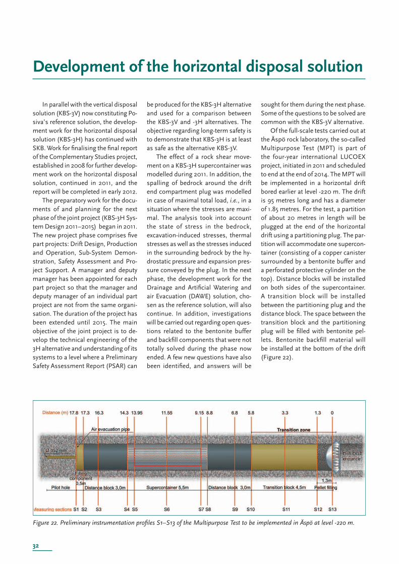
32
Development of the horizontal disposal solution
Figure 22. Preliminary instrumentation profi les S1–S13 of the Multipurpose Test to be implemented in Äspö at level -220 m.
In parallel with the vertical disposal solution (KBS-3V) now constituting Po-siva’s reference solution, the develop-ment work for the horizontal disposal solution (KBS-3H) has continued with SKB. Work for fi nalising the fi nal report of the Complementary Studies project, established in 2008 for further develop-ment work on the horizontal disposal solution, continued in 2011, and the report will be completed in early 2012.
The preparatory work for the docu-ments of and planning for the next phase of the joint project (KBS-3H Sys-tem Design 2011–2015) began in 2011. The new project phase comprises fi ve part projects: Drift Design, Production and Operation, Sub-System Demon-stration, Safety Assessment and Pro-ject Support. A manager and deputy manager has been appointed for each part project so that the manager and deputy manager of an individual part project are not from the same organi-sation. The duration of the project has been extended until 2015. The main objective of the joint project is to de-velop the technical engineering of the 3H alternative and understanding of its systems to a level where a Preliminary Safety Assessment Report (PSAR) can
be produced for the KBS-3H alternative and used for a comparison between the KBS-3V and -3H alternatives. The objective regarding long-term safety is to demonstrate that KBS-3H is at least as safe as the alternative KBS-3V.
The effect of a rock shear move-ment on a KBS-3H supercontainer was modelled during 2011. In addition, the spalling of bedrock around the drift end compartment plug was modelled in case of maximal total load, i.e., in a situation where the stresses are maxi-mal. The analysis took into account the state of stress in the bedrock, excavation-induced stresses, thermal stresses as well as the stresses induced in the surrounding bedrock by the hy-drostatic pressure and expansion pres-sure conveyed by the plug. In the next phase, the development work for the Drainage and Artifi cial Watering and air Evacuation (DAWE) solution, cho-sen as the reference solution, will also continue. In addition, investigations will be carried out regarding open ques-tions related to the bentonite buffer and backfi ll components that were not totally solved during the phase now ended. A few new questions have also been identifi ed, and answers will be
sought for them during the next phase. Some of the questions to be solved are common with the KBS-3V alternative.
Of the full-scale tests carried out at the Äspö rock laboratory, the so-called Multipurpose Test (MPT) is part of the four-year international LUCOEX project, initiated in 2011 and scheduled to end at the end of 2014. The MPT will be implemented in a horizontal drift bored earlier at level -220 m. The drift is 95 metres long and has a diameter of 1.85 metres. For the test, a partition of about 20 metres in length will be plugged at the end of the horizontal drift using a partitioning plug. The par-tition will accommodate one supercon-tainer (consisting of a copper canister surrounded by a bentonite buffer and a perforated protective cylinder on the top). Distance blocks will be installed on both sides of the supercontainer. A transition block will be installed between the partitioning plug and the distance block. The space between the transition block and the partitioning plug will be fi lled with bentonite pel-lets. Bentonite backfi ll material will be installed at the bottom of the drift (Figure 22).
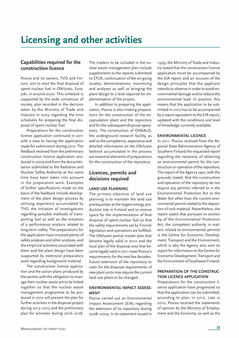
33
Licensing and other activities
Management of spent fuel
Capabilities required for the construction licence
Posiva and its owners, TVO and For-tum, aim to start the fi nal disposal of spent nuclear fuel in Olkiluoto, Eura-joki, in around 2020. This schedule is supported by the wide consensus of society, also recorded in the decision taken by the Ministry of Trade and Industry in 2003 regarding the time schedules for preparing the fi nal dis-posal of spent nuclear fuel.
Preparations for the construction licence application continued in 2011 with a view to having the application ready for submission during 2012. The feedback received from the preliminary construction licence application pro-duced in 2009 and from the documen-tation submitted to the Radiation and Nuclear Safety Authority at the same time have been taken into account in the preparation work. Examples of further specifi cations made on the basis of the feedback include develop-ment of the plant design process by utilising experience accumulated by TVO, the initiation of investigations regarding possible methods of trans-porting fuel as well as the initiation of a performance analysis related to long-term safety. The preparations for the application have involved plenty of safety analyses and other analyses, and the empirical activities associated with them and the plant design have been supported by extensive preparatory work regarding background material.
The construction licence applica-tion and the action plans produced by the parties with the obligation to man-age their nuclear waste are to be linked together so that the nuclear waste management programme to be pro-duced in 2012 will present the plan for further activities in the disposal project during 2013–2015 and the preliminary plan for activities during 2016–2108.
The matters to be included in the nu-clear waste management plan include supplements to the reports submitted to STUK, continuation of the on-going studies, demonstrations, monitoring and analyses as well as bringing the plant design to a level required for im-plementation of the project.
In addition to preparing the appli-cation, Posiva is also making prepara-tions for the construction of the en-capsulation plant and the repository and for the subsequent disposal opera-tions. The construction of ONKALO, the underground research facility, as well as the competence, experience and detailed information on the Olkiluoto bedrock accumulated in the process are essential elements of preparations for the construction of the repository.
Licences, permits and decisions required
LAND USE PLANNINGThe primary objective of land use planning is to maintain the land use prerequisites at the largest energy pro-duction site in Finland and to reserve space for the implementation of fi nal disposal of spent nuclear fuel so that the safety requirements set by Finnish legislation and operations are fulfi lled. The Olkiluoto partial master plan that became legally valid in 2010 and the local plan of the disposal area that be-came legally valid in 2011 meet Posiva’s requirements for the next few decades. Future extension of the repository to cater for the disposal requirements of new plant units may require the current land use plans to be changed.
ENVIRONMENTAL IMPACT ASSESS-MENTPosiva carried out an Environmental Impact Assessment (EIA) regarding the extension of its repository during 2008–2009. In its statement issued in
1999, the Ministry of Trade and Indus-try stated that the construction licence application must be accompanied by the EIA report and an account of the design principles that the applicant intends to observe in order to avoid en-vironmental damage and to reduce the environmental load. In practice, this means that the application to be sub-mitted in 2012 has to be accompanied by a report equivalent to the EIA report, updated with the conditions and level of knowledge currently available.
ENVIRONMENTAL LICENCEIn 2011, Posiva received from the Re-gional State Administration Agency of Southern Finland the requested report regarding the necessity of obtaining an environmental permit for the con-struction or operation of the repository. The report of the Agency says, with the grounds stated, that the construction and operation of the repository do not require any permits referred to in the Environmental Protection Act or the Water Act other than the current envi-ronmental permit related to the deposi-tion of rock material. Nevertheless, the report states that pursuant to section 84 of the Environmental Protection Act, the competent authority in mat-ters related to environmental permits is the Centre for Economic Develop-ment, Transport and the Environment, which is why the Agency also sent its report for information to the Centre for Economic Development, Transport and the Environment of Southwest Finland.
PREPARATION OF THE CONSTRUC-TION LICENCE APPLICATIONPreparations for the construction li-cence application have progressed so that the application can be submitted, according to plan, in 2012. Late in 2010, Posiva received the statements of opinion by the Ministry of Employ-ment and the Economy, as well as the
34
statements of opinion submitted to the Ministry, regarding the preliminary licence application documentation prepared by Posiva in 2009. A detailed statement of opinion regarding the preliminary reports submitted to STUK in 2009 was received during 2011. The views expressed in the statements have been included in the preparatory work for the actual construction licence ap-plication.
Management of quality, the environment and occupational safety
OPERATIONS MANAGEMENT SYSTEMPosiva has been organised as a line organisation, but since 2011, the com-pany has mainly operated through its functional processes. The migration towards a process-based management system will take place over several years. The change is in progress for budgeting, for example. Posiva holds ISO 9001 certifi cation.
The role of ONKALO’s monitor-ing group was partially redefi ned in connection with the process reform. The group is responsible for ensur-ing that the TKS and Investments and Construction processes have up-to-date design bases in place that fulfi l the safety requirements and that the processes are conducted accordingly. In addition to the above processes, the activities of the group also cover the associated processes set up for qual-ity and safety management. The group acts as the decision-making and steer-ing body for Posiva’s project activities. The group’s activities assist Posiva’s management in steering the process activities by making decisions on the KBS-3 disposal system and by oversee-ing the achievement of the objectives set for ONKALO.
STUK controlled the construction of ONKALO in keeping with the agreed procedures. STUK carried out its in-spection plan regarding the construc-tion of ONKALO as planned. Regular STUK follow-up meetings were held between STUK and Posiva, and sepa-rate site inspections were performed. The STUK-approved schedule for sub-
mitting ONKALO design documents and the plan for giving information on construction details were observed in the ONKALO construction project.
CONTROL OF ENVIRONMENTAL IMPACTSPosiva manages environmental mat-ters in line with its operations manage-ment system and annual environmen-tal programme. Posiva’s environmen-tal system, included in its operations management system, has held ISO 14001 certifi cation since 2010.
No major environmental events occurred in 2011. Chemical spillages continue to pose the most signifi cant evironmental risks. There was also scope for development in the sorting of conventional municipal waste.
In 2011, the excavation work in ONKALO produced some 125,000 m3 of rock waste, part of which was used for building works in the area. A total of 28,000 m3 of water was used in constructing the tunnel. The average rate of water leakage in ONKALO was approximately 33 l/min. The waters pumped from the tunnel (operational water and leakage waters) were fi rst led to sedimentation and oil separation and then to the sea via an open ditch. The quality of the water was regularly monitored.
OCCUPATIONAL SAFETYThe principles and practical proce-dures observed in occupational safety management at Posiva are described in its operations management system. Many of the occupational safety risks associated with working underground are in many ways more difficult to control than those associated with work above ground. For example, the occurrences of rocks and boulders fall-ing off the bedrock face after excavation work as a result of relaxing bedrock stresses can only be completely con-trolled by reinforcing the entire exca-vated bedrock face. In the repository, such a procedure confl icts with both Posiva’s own research activities and with offi cial inspections. The risk of falling rocks materialised in early 2011 as an experienced rock construction
worker, employed by the excavation contractor, was killed in ONKALO. Af-ter the incident, the conditions of rock construction work were changed so that working in non-reinforced facilities was virtually banned.
In construction work above ground, the problems in 2011 were minor acci-dents in the ventilation and hoist build-ings site. The individual incidents were minor, but there were many of them resulting in sick leave of a few days. The investigations carried out seem to indicate that the use of subcontractors with poor knowledge of local condi-tions was the key factor contributing to these unwelcome developments. The procedures and Posiva’s supervision will be revised in this respect.
Posiva’s OHS system was granted an OHSAS 18001 certifi cate in 2011. The management of OHS matters was enhanced in 2011 by transferring the function under the corporate safety and security process. The personnel resources were also organised ac-cordingly.
Information management
KNOWLEDGE MANAGEMENTThe information in an organisation consists of tacit information and of implicit and explicit information, i.e., information expressed in written form.
Knowledge management often con-centrates on the systematic manage-ment of explicit information required for the operations of a company or organisation. In its wider application, knowledge management also includes areas of HR and competence manage-ment, such as transfer of information from one generation to the next using different procedures before people re-tire or move to different positions or organisations.
Posiva and its interest groups in-tend to ensure that basic knowledge is preserved at least over the coming decades and the coming century as employees and generations change. The threat is the discontinuation of disposal activities if doubts are raised for whatever reason that the long-term safety has fl aws, and the bases of the
35Management of spent fuel
analyses are no longer recalled and understood.
For the purpose of developing knowledge management, a KMS pro-ject was initiated in 2011. Its purpose is to design and implement a search portal for both internal use and external use that will be restricted using existing identifi cation tool technology. Another purpose is to organise the information content of the reports produced in the research activities to better facilitate searches and to scan and OCR the published reports only available in printed form and then store them in the document management system. In the course of the project, about 2,300 reports from the archives have been converted into electronic form for storing in Posiva’s report library. The new search portal will be completed in early 2012. Aalto University is also in the process of transferring POSIVA reports and working reports to IAEA’s database.
REQUIREMENTS MANAGEMENTThe VAHA requirements management project was established in 2006 for the purpose of defi ning, planning and implementing a systematic procedure for managing the requirements con-cerning the disposal project. When implementing the project, Posiva’s earlier projects related to requirements management (in particular manage-ment of the requirements concern-ing the ONKALO project) were taken into account, as was the experience accumulated elsewhere, in particular at SKB. The project developed a data system for collecting all requirements concerning disposal and their grounds, details of solutions for meeting the re-
quirements, as well as information on the linkages between different require-ments. The fi rst version of the require-ments database regarding disposal was commissioned in autumn 2007.
The work for defi ning the require-ments and their interdependencies was completed in 2011. Following comple-tion of the work, the requirements management work is performed as a process. The design basis document presenting the rationale behind the requirements from the perspective of long-term safety is a key element of requirements management. The draft version of the design basis report was completed in late 2011 following an extensive round of inspections. An equivalent process of defi ning the de-sign basis is also underway from the perspective of operational safety, and the work for producing more detailed requirements for the different subsys-tems in the encapsulation plant also began in late 2011.
STUK has been provided with re-mote access to the approved require-ment management information.
DOCUMENTATION MANAGEMENTIn late 2011, Posiva started the Devel-opment of documentation manage-ment project. The main objective of the project is to produce a report of the current status of documentation man-agement and an information manage-ment plan that would act as the basis for ensuring that Posiva’s operations are comprehensively documented and that information can be found through-out its entire life span.
RESEARCH DATA SYSTEMSPosiva has a large amount of research
data, collected over a few decades in Olkiluoto and other localities where Po-siva has previously conducted studies and surveys. This extensive collection includes research data on the area’s bedrock, water areas in the surround-ing environment, animal population and weather conditions.
The work on specifying the POTTI system began in 2004 with the speci-fi cation of data to be stored, intended uses of the database, the operating environment and the extent of data-base usage. The production use of the POTTI system began in March 2007, and different areas of research (hydro-geochemistry, hydrology, environmen-tal monitoring, geology, geophysics, excavation documentation, rock me-chanics) have gradually increased its use during 2007–2011. Among others things, the POTTI system has inter-faces with the automatic groundwater measuring system in ONKALO, the HYPERDATA borehole data system and the Surpac geological modelling system. The POTTI development work undertaken during 2011 focussed on verifying the correctness of information and on stabilising the system while the work for saving research data contin-ued as usual.
Posiva’s HYPERDATA system is intended for viewing and visualising Olkiluoto borehole data, and it utilises the research data stored in the POTTI research data system. The images of bore core box contents from Olkiluoto and ONKALO boreholes as well as the images of borehole walls and acoustic images were processed and stored in the POTTI system during 2008–2011. The system also has available tunnel images from ONKALO.
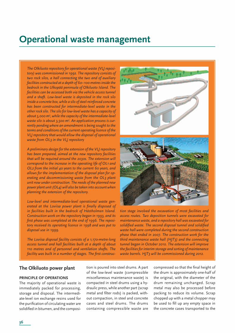
36
Operational waste management
The Olkiluoto repository for operational waste (VLJ reposi-tory) was commissioned in 1992. The repository consists of two rock silos, a hall connecting the two and of auxiliary facilities constructed at a depth of 60–100 metres inside the bedrock in the Ulkopää peninsula of Olkiluoto Island. The facilities can be accessed both via the vehicle access tunnel and a shaft. Low-level waste is deposited in the rock silo inside a concrete box, while a silo of steel-reinf orced concrete has been constructed for intermediate-level waste in the other rock silo. The silo for low-level waste has a capacity of about 5,000 m3, while the capacity of the intermediate-level waste silo is about 3,500 m3. An application process is cur-rently pending where an amendment is being sought to the terms and conditions of the current operating licence of the VLJ repository that would allow the disposal of operational waste from OL3 in the VLJ repository
A preliminary design for the extension of the VLJ repository has been prepared, aimed at the new repository facilities that will be required around the 2030s. The extension will correspond to the increase in the operating life of OL1 and OL2 from the initial 40 years to the current 60 years, and allows for the implementation of the disposal plan for op-erating and decommissioning waste from the OL3 plant unit now under construction. The needs of the planned new power plant unit (OL4) will also be taken into account when planning the extension of the repository.
Low-level and intermediate-level operational waste gen-erated at the Loviisa power plant is fi nally disposed of in facilities built in the bedrock of Hästholmen Island. Construction work on the repository began in 1993, and its fi rst phase was completed at the end of 1996. The reposi-tory received its operating licence in 1998 and was put to disposal use in 1999.
The Loviisa disposal facility consists of a 1,170-metre-long access tunnel and hall facilities built at a depth of about 110 metres and of personnel and ventilation shafts. The facility was built in a number of stages. The fi rst construc-
tion stage involved the excavation of most facilities and access routes. Two deposition tunnels were excavated for maintenance waste, and a repository hall was excavated for solidifi ed waste. The second disposal tunnel and solidifi ed waste hall were completed during the second construction phase that ended in 2007. The construction work for the third maintenance waste hall (HJT3) and the connecting tunnel began in October 2010. The extension will improve the facilities for interim storage and sorting of maintenance waste barrels. HJT3 will be commissioned during 2012.
The Olkiluoto power plant
PRINCIPLE OF OPERATIONSThe majority of operational waste is immediately packed for processing, storage and disposal. The intermedi-ate-level ion exchange resins used for the purifi cation of circulating water are solidifi ed in bitumen, and the composi-
tion is poured into steel drums. A part of the low-level waste (compressible miscellaneous maintenance waste) is compacted in steel drums using a hy-draulic press, while another part (scrap metal and fi lter rods) is packed, with-out compaction, in steel and concrete cases and steel drums. The drums containing compressible waste are
compressed so that the fi nal height of the drum is approximately one-half of the original, with the diameter of the drum remaining unchanged. Scrap metal may also be processed before packing to reduce its volume. Scrap chopped up with a metal chopper may be used to fi ll up any empty space in the concrete cases transported to the
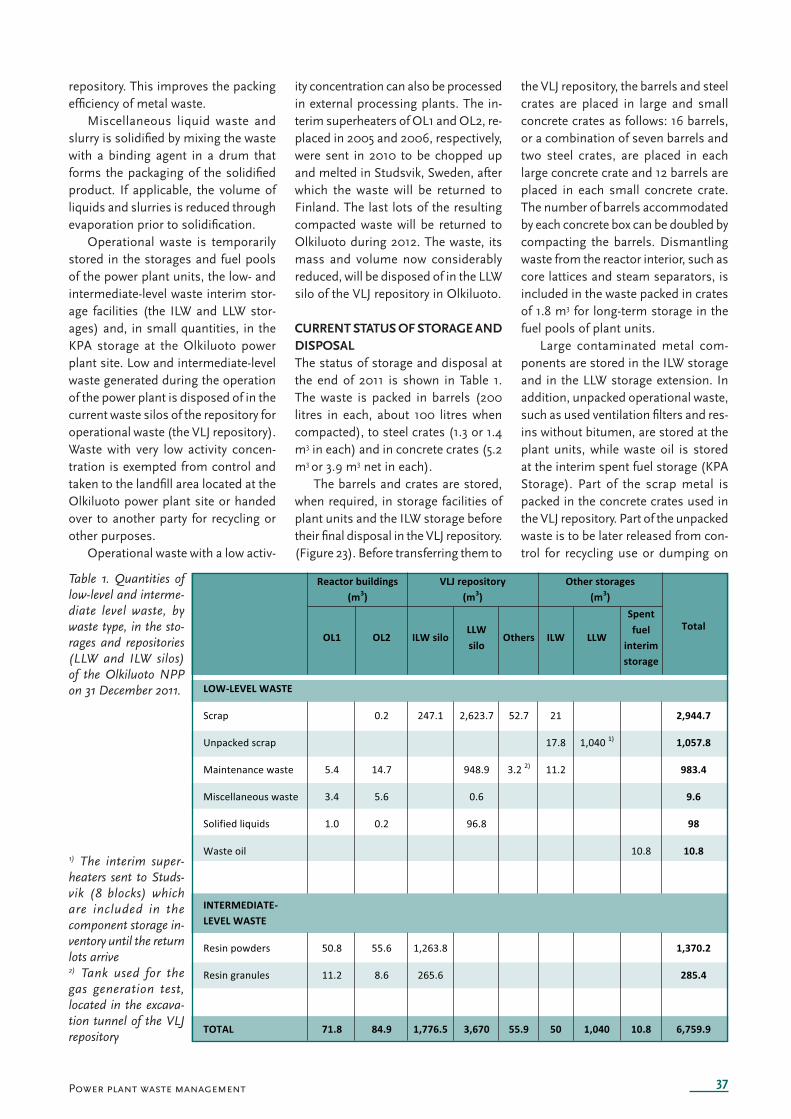
37
Table 1. Quantities of low-level and interme-diate level waste, by waste type, in the sto-rages and repositories (LLW and ILW silos) of the Olkiluoto NPP on 31 December 2011.
Power plant waste management
repository. This improves the packing effi ciency of metal waste.
Miscellaneous liquid waste and slurry is solidifi ed by mixing the waste with a binding agent in a drum that forms the packaging of the solidifi ed product. If applicable, the volume of liquids and slurries is reduced through evaporation prior to solidifi cation.
Operational waste is temporarily stored in the storages and fuel pools of the power plant units, the low- and intermediate-level waste interim stor-age facilities (the ILW and LLW stor-ages) and, in small quantities, in the KPA storage at the Olkiluoto power plant site. Low and intermediate-level waste generated during the operation of the power plant is disposed of in the current waste silos of the repository for operational waste (the VLJ repository). Waste with very low activity concen-tration is exempted from control and taken to the landfi ll area located at the Olkiluoto power plant site or handed over to another party for recycling or other purposes.
Operational waste with a low activ-
ity concentration can also be processed in external processing plants. The in-terim superheaters of OL1 and OL2, re-placed in 2005 and 2006, respectively, were sent in 2010 to be chopped up and melted in Studsvik, Sweden, after which the waste will be returned to Finland. The last lots of the resulting compacted waste will be returned to Olkiluoto during 2012. The waste, its mass and volume now considerably reduced, will be disposed of in the LLW silo of the VLJ repository in Olkiluoto.
CURRENT STATUS OF STORAGE AND DISPOSALThe status of storage and disposal at the end of 2011 is shown in Table 1. The waste is packed in barrels (200 litres in each, about 100 litres when compacted), to steel crates (1.3 or 1.4 m3 in each) and in concrete crates (5.2 m3 or 3.9 m3 net in each).
The barrels and crates are stored, when required, in storage facilities of plant units and the ILW storage before their fi nal disposal in the VLJ repository. (Figure 23). Before transferring them to
the VLJ repository, the barrels and steel crates are placed in large and small concrete crates as follows: 16 barrels, or a combination of seven barrels and two steel crates, are placed in each large concrete crate and 12 barrels are placed in each small concrete crate. The number of barrels accommodated by each concrete box can be doubled by compacting the barrels. Dismantling waste from the reactor interior, such as core lattices and steam separators, is included in the waste packed in crates of 1.8 m3 for long-term storage in the fuel pools of plant units.
Large contaminated metal com-ponents are stored in the ILW storage and in the LLW storage extension. In addition, unpacked operational waste, such as used ventilation fi lters and res-ins without bitumen, are stored at the plant units, while waste oil is stored at the interim spent fuel storage (KPA Storage). Part of the scrap metal is packed in the concrete crates used in the VLJ repository. Part of the unpacked waste is to be later released from con-trol for recycling use or dumping on
1) The interim super-heaters sent to Studs-vik (8 blocks) which are included in the component storage in-ventory until the return lots arrive2) Tank used for the gas generation test, located in the excava-tion tunnel of the VLJ repository
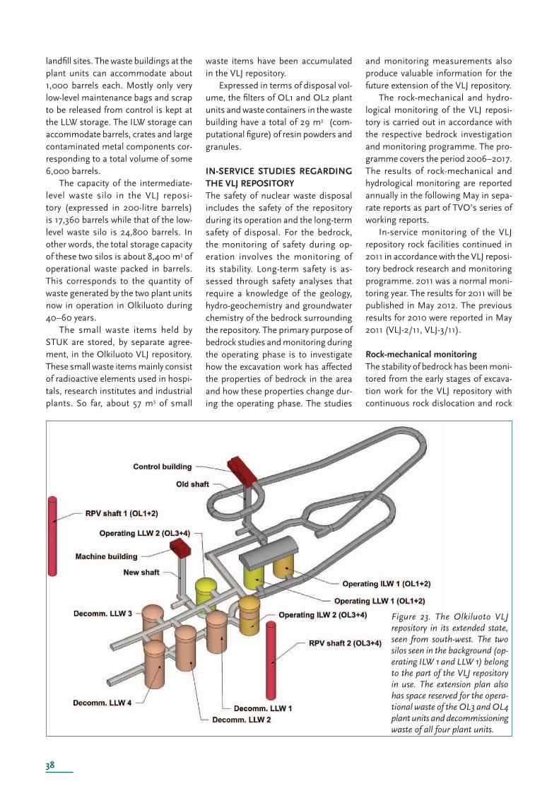
38
F igure 23. The Olkiluoto VLJ repository in its extended state, seen from south-west. The two silos seen in the background (op-erating ILW 1 and LLW 1) belong to the part of the VLJ repository in use. The extension plan also has space reserved for the opera-tional waste of the OL3 and OL4 plant units and decommissioning waste of all four plant units.
landfi ll sites. The waste buildings at the plant units can accommodate about 1,000 barrels each. Mostly only very low-level maintenance bags and scrap to be released from control is kept at the LLW storage. The ILW storage can accommodate barrels, crates and large contaminated metal components cor-responding to a total volume of some 6,000 barrels.
The capacity of the intermediate-level waste silo in the VLJ reposi-tory (expressed in 200-litre barrels) is 17,360 barrels while that of the low-level waste silo is 24,800 barrels. In other words, the total storage capacity of these two silos is about 8,400 m3 of operational waste packed in barrels. This corresponds to the quantity of waste generated by the two plant units now in operation in Olkiluoto during 40–60 years.
The small waste items held by STUK are stored, by separate agree-ment, in the Olkiluoto VLJ repository. These small waste items mainly consist of radioactive elements used in hospi-tals, research institutes and industrial plants. So far, about 57 m3 of small
waste items have been accumulated in the VLJ repository.
Expressed in terms of disposal vol-ume, the fi lters of OL1 and OL2 plant units and waste containers in the waste building have a total of 29 m3 (com-putational fi gure) of resin powders and granules.
IN-SERVICE STUDIES REGARDING THE VLJ REPOSITORYThe safety of nuclear waste disposal includes the safety of the repository during its operation and the long-term safety of disposal. For the bedrock, the monitoring of safety during op-eration involves the monitoring of its stability. Long-term safety is as-sessed through safety analyses that require a knowledge of the geology, hydro-geochemistry and groundwater chemistry of the bedrock surrounding the repository. The primary purpose of bedrock studies and monitoring during the operating phase is to investigate how the excavation work has affected the properties of bedrock in the area and how these properties change dur-ing the operating phase. The studies
and monitoring measurements also produce valuable information for the future extension of the VLJ repository.
The rock-mechanical and hydro-logical monitoring of the VLJ reposi-tory is carried out in accordance with the respective bedrock investigation and monitoring programme. The pro-gramme covers the period 2006–2017. The results of rock-mechanical and hydrological monitoring are reported annually in the following May in sepa-rate reports as part of TVO’s series of working reports.
In-service monitoring of the VLJ repository rock facilities continued in 2011 in accordance with the VLJ reposi-tory bedrock research and monitoring programme. 2011 was a normal moni-toring year. The results for 2011 will be published in May 2012. The previous results for 2010 were reported in May 2011 (VLJ-2/11, VLJ-3/11).
Rock-mechanical monitoringThe stability of bedrock has been moni-tored from the early stages of excava-tion work for the VLJ repository with continuous rock dislocation and rock
39Power plant waste management
bolt loading measurements as well as with measurements of changes in the span dimensions of excavated facilities utilising convergence measurement bolts. A conference presentation enti-tled ‘Two decades of rock monitoring experiences at the two underground repositories for operational waste in Finland’ was prepared during 2010 re-garding the long-term rock-mechanical and groundwater monitoring of the VLJ repositories in Olkiluoto and Loviisa. It was presented at the 2011 World Tun-nel Congress organised in Helsinki in May 2011.
In rock mechanics, a normal meas-urement programme excluding conver-gence measurements was implement-ed in 2011 Convergence measurements were last carried out in 2010, and they are next scheduled for 2015. The rock-mechanical monitoring measurements carried out in 2011 did not indicate any changes in the rock mechanics of the VLJ repository. The mechanical condi-tion of the rock was still good, and no surprises were encountered regard-ing the behaviour of the bedrock. The small changes at the measuring points were due to changes in rock tempera-ture. However, the rock temperatures during the transition behaviour of the rock have stabilised as predicted. Overall, the rock-mechanical measur-ing instruments operated well in 2011. There have still been some minor dis-turbances in some instruments. There was no need to replace extensometer heads during 2011.
In spring 1993, 10 test bolts were installed in the research tunnel of the Olkiluoto VLJ repository for the pur-pose of determining the rate of corro-sion in rock bolts. The purpose of the study is to produce information of the corrosion resistance of zinc-plated rock reinforcement bolts in the conditions prevailing at the Olkiluoto VLJ reposi-tory assuming that the cement plaster protecting the bolts has totally lost its protective properties. The fi rst test bolt was bored out in 1996 and the next one in 2004. The results for the latter bolt were reported in 2006. The results indicate that the rate of corrosion is negligible, which is why the decision
was taken to further postpone the next removal boring until 2014.
Hydrological monitoringThe leakage water fl ow in the VLJ re-pository was monitored by measuring the discharge pump flow rates. No measuring weir measurements were scheduled for 2011. The hydraulic head of groundwater was observed at the automatic measurement points. The amount of rainfall was measured at the Ulkopää peninsula of the Olkiluoto Is-land, and sea level data were obtained from the Rauma observatory of the Meteorological Institute of Finland. Analyses of groundwater chemistry were also performed in 2011.
The measurement results for 2010 were reported in spring 2011 (VLJ-2/11). In 2011, the average leakage water fl ow in the VLJ repository was 41.1 litres/min, slightly higher than in the two previous years. The long-term trend matching of the total fl ow of leakage water still indicates a declining trend, albeit that the total fl ow would seem to have become more constant during the last few years.
The leaking points of the VLJ re-pository are photographed once a year in accordance with the research and monitoring programme. The latest re-ported set of photographs dates back to November 2010.
Groundwater chemistry Extensive monitoring samples were collected from the groundwater sta-tions of the VLJ repository in 2011. The previous extensive sampling campaign took place in spring 2008 when the most signifi cant changes in groundwa-ter quality were the decreased sodium, chloride and potassium concentra-tions.
During years of more limited sam-pling, water samples are taken from the groundwater samples and their basic chemistry is analysed. During years of more extensive sampling, the samples taken from three groundwater stations are also analysed for isotope compositions. In addition to the water samples, a gas sample is also taken from each groundwater station for
analysis of dissolved gases and isotope compositions.
The changes in analysis results dur-ing the period 2008–2011 have been small and all water samples have been neutral. Although the latest analysis results for 2011 lead to the conclusion that a more stable phase has been reached in the groundwater condi-tions of the VLJ repository bedrock, the groundwater chemistry cannot be assumed to be stable yet. The results of sampling in 2011 will be reported during spring 2012.
Air quality in the repository The air quality in the VLJ repository was monitored by radon concentration measurements at various measure-ment points and by exhaust air radioac-tivity measurements. Radon measure-ments have been taken from the VLJ re-pository air since 1991, and the original measurement method was replaced in 2009 by radon detection containers supplied by STUK. The radon concen-tration measurement points are in the same locations as in previous years. In 2011, the measurement period was two months. The changed method and length of the measurement period have not had any signifi cant effect on the results. The measurement results for 2010 were reported in 2011 (VLJ-2/11).
The radon concentration in places of regular work must not exceed the limit value prescribed in the Radiation Decree (400 Bq/m3). In 2011, a concen-tration value exceeding this limit value was measured in the VLJ repository in two measurement points: in the stor-age facilities for STUK’s small waste items (1,100 Bq/m3) and at the meas-urement point located near the LLW silo (450 Bq/m3). The limit value has also been exceeded in these measure-ment points in previous years. In 2011, the radon concentrations in all meas-urement points were of the same order of magnitude as in 2010.
The quality of exhaust air from the VLJ repository has been monitored since 1999. The presence of any radio-active substances in the exhaust air has been investigated by aerosol sampling. The exhaust air was analysed on three

40
Figure 24. Ga s generation test equipment in the VLJ repository of Olkiluoto. Photo: TVO.
occasions during 2011. As in previous years, no radioactive substances were observed in the exhaust air. The tem-perature, relative humidity and carbon dioxide concentration of repository air was also monitored. The average temperature and relative humidity in the repository were in 2011 close to the average values for the entire moni-tored period (1991–2011). Towards the end of the year, the carbon dioxide concentrations in the excavation tun-nel were slightly higher than the 2010 concentrations.
RESEARCH RELATED TO OPERA-TIONAL AND DECOMMISSIONING WASTEGas generation testMicrobiological decay of low-level main-tenance waste in repository conditions is being studied in a large-scale gas generation test performed with test equipment erected in the VLJ repository excavation tunnel (Figure 24). The study has continued since 1997. The study serves to specify further the estimate on the amount and generation rate of gas generated from maintenance waste and to improve knowledge of the impact of microbial activity on the whole decay
process and of the corrosion of steel under conditions which are similar to those after the VLJ repository has been sealed off. The factors important for the processes in the test are the simulation of conditions and variation of materials in the 20 m3 test tank between waste barrel contents and the volume of water between them. Thanks to these hetero-geneous conditions, microbes are more likely to have favourable microenviron-ments, which has already been con-fi rmed by the test results. In addition to chemical monitoring, the release of activity from the waste barrels into the surrounding water is also monitored. The most recent microbiological analy-ses were conducted in 2005.
The objective of the study is to produce an estimate of the gas genera-tion rate for the safety analysis of the VLJ repository that was last updated in 2006. Over a longer period, the gas generation rate has stabilised to 60–90 dm3/month, which is almost one order of magnitude smaller than the value taken for the initial safety analysis of the VLJ repository. The gas being released is mainly methane gen-erated by the reaction of hydrogen and carbon dioxide that already takes place
inside the tank. During the test, the pH of the water between the waste barrels has decreased from alkaline (> 10) to neutral. The decrease is thought to be caused by microbial activity, and it is larger than the expectations that were affected by the alkalinity of concrete. The strong corrosion in the steel sheet samples from barrels also agrees with the change in pH values. The conduc-tivity and redox potential of water have steadily increased over the 10-year pe-riod, to approximately 1,400 mS/m and -300 mV (Eh), respectively.
An interim assessment of the test results was reported in 2011 for the purpose of establishing the changes in test tank conditions as well as any future development or actions required (VLJ-1/11). The gas generation test is permitted to continue until 2017. In the future, at the latest when deciding on the test programme, the need for microbiological analysis work has to be assessed. Information on the develop-ment of pH values during the test can probably also be utilised in the future when the assessment of long-term safety of the disposal of operational waste is revised. The intention is to start the planning for ending the test
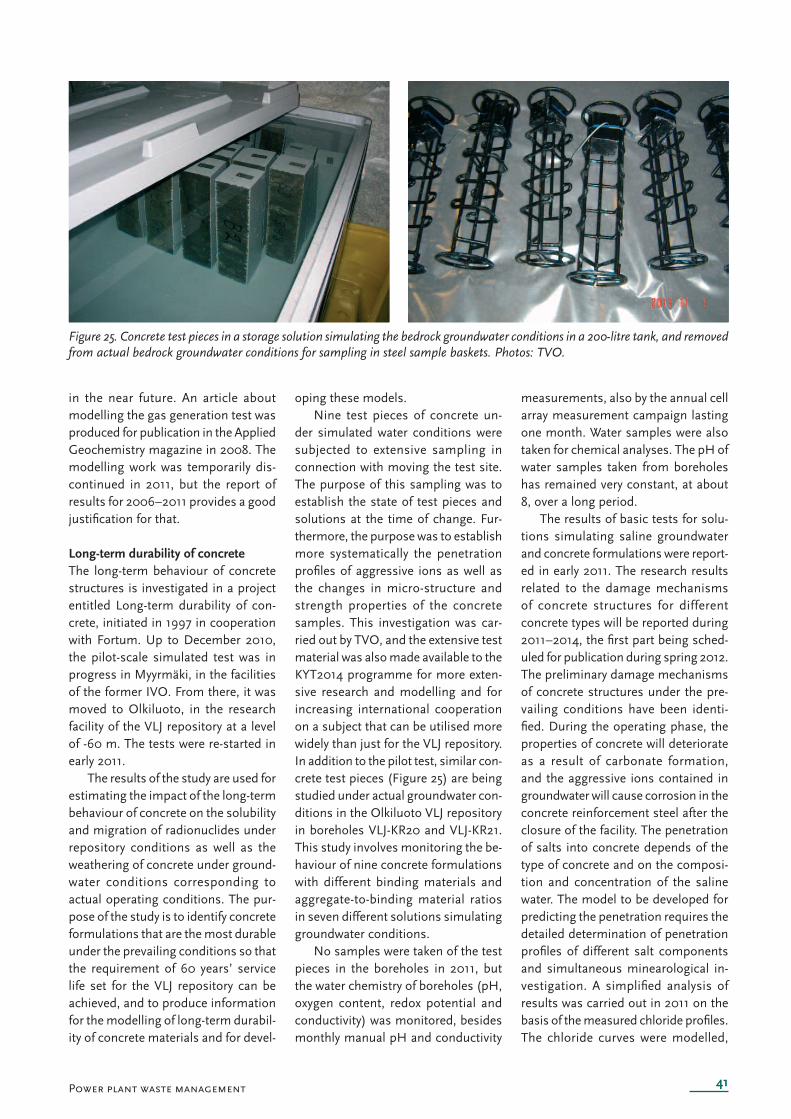
41
Figure 25. Concr ete test pieces in a storage solution simulating the bedrock groundwater conditions in a 200-litre tank, and removed from actual bedrock groundwater conditions for sampling in steel sample baskets. Photos: TVO.
Power plant waste management
in the near future. An article about modelling the gas generation test was produced for publication in the Applied Geochemistry magazine in 2008. The modelling work was temporarily dis-continued in 2011, but the report of results for 2006–2011 provides a good justifi cation for that.
Long-term durability of concreteThe long-term behaviour of concrete structures is investigated in a project entitled Long-term durability of con-crete, initiated in 1997 in cooperation with Fortum. Up to December 2010, the pilot-scale simulated test was in progress in Myyrmäki, in the facilities of the former IVO. From there, it was moved to Olkiluoto, in the research facility of the VLJ repository at a level of -60 m. The tests were re-started in early 2011.
The results of the study are used for estimating the impact of the long-term behaviour of concrete on the solubility and migration of radionuclides under repository conditions as well as the weathering of concrete under ground-water conditions corresponding to actual operating conditions. The pur-pose of the study is to identify concrete formulations that are the most durable under the prevailing conditions so that the requirement of 60 years’ service life set for the VLJ repository can be achieved, and to produce information for the modelling of long-term durabil-ity of concrete materials and for devel-
oping these models.Nine test pieces of concrete un-
der simulated water conditions were subjected to extensive sampling in connection with moving the test site. The purpose of this sampling was to establish the state of test pieces and solutions at the time of change. Fur-thermore, the purpose was to establish more systematically the penetration profi les of aggressive ions as well as the changes in micro-structure and strength properties of the concrete samples. This investigation was car-ried out by TVO, and the extensive test material was also made available to the KYT2014 programme for more exten-sive research and modelling and for increasing international cooperation on a subject that can be utilised more widely than just for the VLJ repository. In addition to the pilot test, similar con-crete test pieces (Figure 25) are being studied under actual groundwater con-ditions in the Olkiluoto VLJ repository in boreholes VLJ-KR20 and VLJ-KR21. This study involves monitoring the be-haviour of nine concrete formulations with different binding materials and aggregate-to-binding material ratios in seven different solutions simulating groundwater conditions.
No samples were taken of the test pieces in the boreholes in 2011, but the water chemistry of boreholes (pH, oxygen content, redox potential and conductivity) was monitored, besides monthly manual pH and conductivity
measurements, also by the annual cell array measurement campaign lasting one month. Water samples were also taken for chemical analyses. The pH of water samples taken from boreholes has remained very constant, at about 8, over a long period.
The results of basic tests for solu-tions simulating saline groundwater and concrete formulations were report-ed in early 2011. The research results related to the damage mechanisms of concrete structures for different concrete types will be reported during 2011–2014, the fi rst part being sched-uled for publication during spring 2012. The preliminary damage mechanisms of concrete structures under the pre-vailing conditions have been identi-fi ed. During the operating phase, the properties of concrete will deteriorate as a result of carbonate formation, and the aggressive ions contained in groundwater will cause corrosion in the concrete reinforcement steel after the closure of the facility. The penetration of salts into concrete depends of the type of concrete and on the composi-tion and concentration of the saline water. The model to be developed for predicting the penetration requires the detailed determination of penetration profi les of different salt components and simultaneous minearological in-vestigation. A simplifi ed analysis of results was carried out in 2011 on the basis of the measured chloride profi les. The chloride curves were modelled,
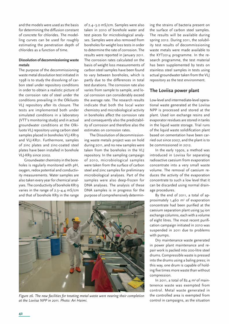
42
Figure 26. The new faciliti es for treating metal waste were nearing their completion at the Loviisa NPP in 2011. Photo: Ari Haimi.
and the models were used as the basis for determining the diffusion constant of concrete for chlorides. The model-ling curves can be used for roughly estimating the penetration depth of chlorides as a function of time.
Dissolution of decommissioning waste metalsThe purpose of the decommissioning waste metal dissolution test initiated in 1998 is to study the dissolving of car-bon steel under repository conditions in order to obtain a realistic picture of the corrosion rate of steel under the conditions prevailing in the Olkiluoto VLJ repository after its closure. The tests are implemented both under simulated conditions in a laboratory (VTT’s monitoring study) and in actual groundwater conditions at the Olki-luoto VLJ repository using carbon steel samples placed in boreholes VLJ-KR19 and VLJ-KR21. Furthermore, samples of zinc plates and zinc-coated steel plates have been installed in borehole VLJ-KR9 since 2002.
Groundwater chemistry in the bore-holes is regularly monitored with pH, oxygen, redox potential and conductiv-ity measurements. Water samples are also taken every year for chemical anal-yses. The conductivity of borehole KR19 varies in the range of 2.3–4.4 mS/cm and that of borehole KR9 in the range
of 2.4–3.0 mS/cm. Samples were also taken in 2010 of borehole water and test pieces for microbiological analy-ses. Samples were also removed from boreholes for weight loss tests in order to determine the rate of corrosion. The results were reported in January 2011. The corrosion rates calculated on the basis of weight loss measurements of carbon steel samples have been found to vary between boreholes, which is partly due to the differences in total test durations. The corrosion rate also varies from sample to sample, and lo-cal corrosion can considerably exceed the average rate. The research results indicate that both the local water chemistry and microbiological activity in boreholes affect the corrosion rate and consequently also the predictabil-ity of corrosion and therefore also the estimates on corrosion rates.
The Dissolution of decommission-ing waste metals project was on hold during 2011, and no new samples were taken from the boreholes in the VLJ repository. In the sampling campaign of 2010, microbiological samples were taken from the surface of carbon steel and zinc samples for preliminary microbiological analyses. Part of the samples were also deep-frozen for DNA analyses. The analysis of these DNA samples is in progress for the purpose of comprehensively determin-
ing the strains of bacteria present on the surface of carbon steel samples. The results will be available during spring 2012. During 2011, the solubil-ity test results of decommissioning waste metals were made available to the KYT2014 programme. In the re-search programme, the test material has been supplemented by tests on stainless steel samples in tests using actual groundwater taken from the VLJ repository as the test environment.
The Loviisa power plant
Low-level and intermediate-level opera-tional waste generated at the Loviisa NPP is processed and stored at the plant. Used ion exchange resins and evaporator residues are stored in tanks in the liquid waste storage. Trial runs of the liquid waste solidifi cation plant based on cementation have been car-ried out since 2007, and the plant is to be commissioned in 2012.
In the early 1990s, a method was introduced in Loviisa for separating radioactive caesium from evaporation concentrate into a very small waste volume. The removal of caesium re-duces the activity of the evaporation concentrate to such a low level that it can be discarded using normal drain-age procedures.
By the end of 2011, a total of ap-proximately 1,460 m3 of evaporation concentrate had been purifi ed at the caesium separation plant using 34 ion exchange columns, each with a volume of eight litres. The most recent purifi -cation campaign initiated in 2010 was suspended in 2011 due to problems with pumps.
Dry maintenance waste generated in power plant maintenance and re-pair work is packed into 200-litre steel drums. Compressible waste is pressed into the drums using a baling press; in this way, one drum is capable of hold-ing fi ve times more waste than without compression.
In 2011, a total of 82.4 m3 of main-tenence waste was exempted from control. Metal waste generated in the controlled area is exempted from control in campaigns, as the situation
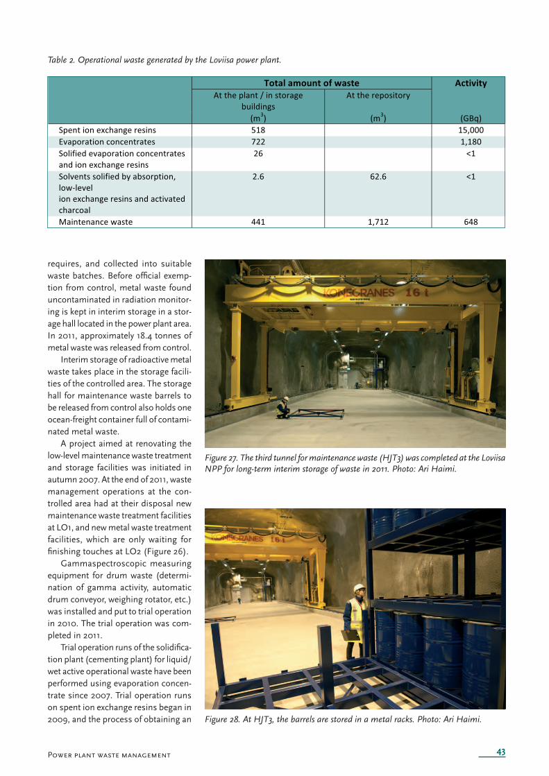
43
Table 2. Operational waste generated by the Loviisa power plant.
Figure 27. The third tunnel for maintenance waste (HJT3) was completed at the Loviisa NPP for long-term interim storage of waste in 2011. Photo: Ari Haimi.
Figure 28. At HJT3, the barrels are stored in a metal racks. Photo: Ari Haimi.
Power plant waste management
requires, and collected into suitable waste batches. Before offi cial exemp-tion from control, metal waste found uncontaminated in radiation monitor-ing is kept in interim storage in a stor-age hall located in the power plant area. In 2011, approximately 18.4 tonnes of metal waste was released from control.
Interim storage of radioactive metal waste takes place in the storage facili-ties of the controlled area. The storage hall for maintenance waste barrels to be released from control also holds one ocean-freight container full of contami-nated metal waste.
A project aimed at renovating the low-level maintenance waste treatment and storage facilities was initiated in autumn 2007. At the end of 2011, waste management operations at the con-trolled area had at their disposal new maintenance waste treatment facilities at LO1, and new metal waste treatment facilities, which are only waiting for fi nishing touches at LO2 (Figure 26).
Gammaspectroscopic measuring equipment for drum waste (determi-nation of gamma activity, automatic drum conveyor, weighing rotator, etc.) was installed and put to trial operation in 2010. The trial operation was com-pleted in 2011.
Trial operation runs of the solidifi ca-tion plant (cementing plant) for liquid/wet active operational waste have been performed using evaporation concen-trate since 2007. Trial operation runs on spent ion exchange resins began in 2009, and the process of obtaining an
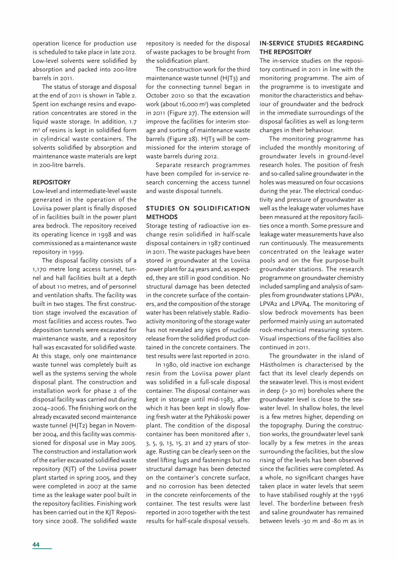
44
operation licence for production use is scheduled to take place in late 2012. Low-level solvents were solidifi ed by absorption and packed into 200-litre barrels in 2011.
The status of storage and disposal at the end of 2011 is shown in Table 2. Spent ion exchange resins and evapo-ration concentrates are stored in the liquid waste storage. In addition, 1.7 m3 of resins is kept in solidifi ed form in cylindrical waste containers. The solvents solidifi ed by absorption and maintenance waste materials are kept in 200-litre barrels.
REPOSITORYLow-level and intermediate-level waste generated in the operation of the Loviisa power plant is fi nally disposed of in facilities built in the power plant area bedrock. The repository received its operating licence in 1998 and was commissioned as a maintenance waste repository in 1999.
The disposal facility consists of a 1,170 metre long access tunnel, tun-nel and hall facilities built at a depth of about 110 metres, and of personnel and ventilation shafts. The facility was built in two stages. The fi rst construc-tion stage involved the excavation of most facilities and access routes. Two deposition tunnels were excavated for maintenance waste, and a repository hall was excavated for solidifi ed waste. At this stage, only one maintenance waste tunnel was completely built as well as the systems serving the whole disposal plant. The construction and installation work for phase 2 of the disposal facility was carried out during 2004–2006. The fi nishing work on the already excavated second maintenance waste tunnel (HJT2) began in Novem-ber 2004, and this facility was commis-sioned for disposal use in May 2005. The construction and installation work of the earlier excavated solidifi ed waste repository (KJT) of the Loviisa power plant started in spring 2005, and they were completed in 2007 at the same time as the leakage water pool built in the repository facilities. Finishing work has been carried out in the KJT Reposi-tory since 2008. The solidifi ed waste
repository is needed for the disposal of waste packages to be brought from the solidifi cation plant.
The construction work for the third maintenance waste tunnel (HJT3) and for the connecting tunnel began in October 2010 so that the excavation work (about 16,000 m3) was completed in 2011 (Figure 27). The extension will improve the facilities for interim stor-age and sorting of maintenance waste barrels (Figure 28). HJT3 will be com-missioned for the interim storage of waste barrels during 2012.
Separate research programmes have been compiled for in-service re-search concerning the access tunnel and waste disposal tunnels.
STUDIES ON SOLIDIFICATION METHODSStorage testing of radioactive ion ex-change resin solidifi ed in half-scale disposal containers in 1987 continued in 2011. The waste packages have been stored in groundwater at the Loviisa power plant for 24 years and, as expect-ed, they are still in good condition. No structural damage has been detected in the concrete surface of the contain-ers, and the composition of the storage water has been relatively stable. Radio-activity monitoring of the storage water has not revealed any signs of nuclide release from the solidifi ed product con-tained in the concrete containers. The test results were last reported in 2010.
In 1980, old inactive ion exchange resin from the Loviisa power plant was solidifi ed in a full-scale disposal container. The disposal container was kept in storage until mid-1983, after which it has been kept in slowly fl ow-ing fresh water at the Pyhäkoski power plant. The condition of the disposal container has been monitored after 1, 3, 5, 9, 13, 15, 21 and 27 years of stor-age. Rusting can be clearly seen on the steel lifting lugs and fastenings but no structural damage has been detected on the container's concrete surface, and no corrosion has been detected in the concrete reinforcements of the container. The test results were last reported in 2010 together with the test results for half-scale disposal vessels.
IN-SERVICE STUDIES REGARDING THE REPOSITORYThe in-service studies on the reposi-tory continued in 2011 in line with the monitoring programme. The aim of the programme is to investigate and monitor the characteristics and behav-iour of groundwater and the bedrock in the immediate surroundings of the disposal facilities as well as long-term changes in their behaviour.
The monitoring programme has included the monthly monitoring of groundwater levels in ground-level research holes. The position of fresh and so-called saline groundwater in the holes was measured on four occasions during the year. The electrical conduc-tivity and pressure of groundwater as well as the leakage water volumes have been measured at the repository facili-ties once a month. Some pressure and leakage water measurements have also run continuously. The measurements concentrated on the leakage water pools and on the fi ve purpose-built groundwater stations. The research programme on groundwater chemistry included sampling and analysis of sam-ples from groundwater stations LPVA1, LPVA2 and LPVA4. The monitoring of slow bedrock movements has been performed mainly using an automated rock-mechanical measuring system. Visual inspections of the facilities also continued in 2011.
The groundwater in the island of Hästholmen is characterised by the fact that its level clearly depends on the seawater level. This is most evident in deep (> 30 m) boreholes where the groundwater level is close to the sea-water level. In shallow holes, the level is a few metres higher, depending on the topography. During the construc-tion works, the groundwater level sank locally by a few metres in the areas surrounding the facilities, but the slow rising of the levels has been observed since the facilities were completed. As a whole, no signifi cant changes have taken place in water levels that seem to have stabilised roughly at the 1996 level. The borderline between fresh and saline groundwater has remained between levels -30 m and -80 m as in
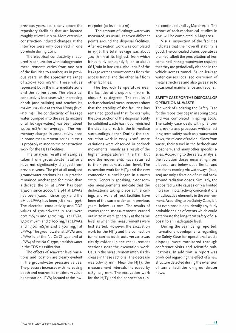
45Power plant waste management
previous years, i.e. clearly above the repository facilities that are located roughly at level -110 m. More extensive construction-induced changes at the interface were only observed in one borehole during 2011.
The electrical conductivity meas-ured in conjunction with leakage water measurements varies from one part of the facilities to another, as in previ-ous years, in the approximate range of 400–1,300 mS/m. These values represent both the intermediate zone and the saline zone. The electrical conductivity increases with increasing depth (and salinity) and reaches its maximum value at station LPVA5 (level -110 m). The conductivity of leakage water pumped into the sea (a mixture of all leakage waters) has been about 1,000 mS/m on average. The mo-mentary change in conductivity seen in some measurement series in 2011 is probably related to the construction work for the HJT3 facilities.
The analysis results of samples taken from groundwater stations have not signifi cantly changed from previous years. The pH at all analysed groundwater stations has in practice remained unchanged for more than a decade: the pH at LPVA1 has been 7.3±0.1 since 2000, the pH at LPVA2 has been 7.2±0.1 since 1997 and the pH at LPVA4 has been 7.6 since 1996. The electrical conductivity and TDS values of groundwater in 2011 were 900 mS/m and 5,100 mg/l at LPVA1, 1,300 mS/m and 7,500 mg/l at LPVA2 and 1,300 mS/m and 7 500 mg/l at LPVA4. The groundwater at LPVA1 and LPVA2 is of the Na-Ca-Cl type and at LPVA4 of the Na-Cl type, brackish water in the TDS classifi cation.
The effects of seawater level varia-tions and location are clearly evident in the groundwater pressure values. The pressure increases with increasing depth and reaches its maximum value bar at station LPVA5 located at the low-
est point (at level -110 m). The amount of leakage water was
measured, as usual, at seven different points around the disposal facilities. After excavation work was completed in 1996, the total leakage was about 300 l/min at its highest, from which it has fairly constantly fallen to about 66 l/min in late 2011. About half of the leakage water amount comes from the access tunnel and the other half from other facilities.
The bedrock temperature near the facilities at a depth of -110 m is about 8–12 degrees. The results of rock-mechanical measurements show that the stability of the facilities has remained good and that, for example, the construction of the disposal facility for solidifi ed waste has not diminished the stability of rock in the immediate surroundings either. During the con-struction work in 2005–2006, more variations were observed in bedrock movements, mainly as a result of the higher temperature in the hall, but now the movements have returned to their pre-construction level. The excavation work for HJT3 and the new connection tunnel began in autumn 2010. Generally speaking, extensom-eter measurements indicate that the dislocations taking place at the ceil-ings and walls of rock facilities have been of the same order as in previous years, below 0.1 mm. The results of convergence measurements carried out in 2010 were generally at the same level as when the measurements were fi rst started. However, the excavation work for the HJT3 and the connection tunnel carried out in autumn 2010 was clearly evident in the measurement sections near the excavation work. Usually the measurement intervals de-crease in these sections. The decrease was 0.6–1.5 mm. Near the HJT3, the measurement intervals increased by 0.85–1.15 mm. The excavation work for the HJT3 and the connection tun-
nel continued until 25 March 2011. The report of rock-mechanical studies in 2011 will be completed in May 2012.
Visual inspection of the facilities indicates that their overall stability is good. The concealed drains operate as planned, albeit the precipitation of iron contained in the groundwater requires that they are periodically cleaned in the vehicle access tunnel. Saline leakage water causes localised corrosion of metal structures and also gives rise to occasional maintenance and repairs.
SAFETY CASE FOR THE DISPOSAL OF OPERATIONAL WASTEThe work of updating the Safety Case for the repository began in spring 2004 and was completed in spring 2006. The safety case deals with phenom-ena, events and processes which affect long-term safety, such as groundwater fl ows, the release of radionuclides from waste, their travel in the bedrock and biosphere, and many other specifi c is-sues. According to the safety analysis, the radiation doses emanating from disposal are below dose limits, and the doses coming via waterways (lake, sea) are only a fraction of natural back-ground radiation doses. Similarly, the deposited waste causes only a limited increase in total activity concentrations of radioactive elements in the environ-ment. According to the Safety Case, it is not even possible to identify any fairly probable chains of events which could deteriorate the long-term safety of dis-posal to an inadequate level.
During the year being reported, international developments regarding the Safety Case for operational waste disposal were monitored through conference visits and scientifi c pub-lications. In addition, a report was produced regarding the effect of a new structure detected during the extension of tunnel facilities on groundwater fl ows.
46
Decommissioning planning
According to the Nuclear Energy Act, the NPP licence holder is also responsible for decommissioning the plant. In order to fulfi l this obligation, the party responsible for waste management must produce a report on the decommissioning methods and schedule as well as on the storage and fi nal disposal of decommissioning waste. The power companies have presented their updated decommissioning plans at fi ve-year intervals until 2008 when the statutory requirement for the frequency of submitting updated decommissioning plans was changed to every six years. The most recent updated plan was completed late in 2008 for both the Loviisa and Olkiluoto nuclear facilities.
Decommissioning
The Olkiluoto power plant
The decommissioning studies are aimed at the technical and economic de-velopment of the dismantling plan and at specifying the initial data for the safety analysis. The decommissioning plan of Olkiluoto NPP was last updated in 2008. The update also included an update of the long-term safety analysis of the dis-posal of decommissioning waste. Most of the plan only applies to the plant units currently in operation, but the decom-missioning waste from four plant units were taken into account in the long term safety analysis. Furthermore, in 2008 a preliminary plan was completed for an extension to the disposal facilities for reactor and decommissioning waste; here, too, the waste from the two new plant units was taken into account in ad-dition to the units currently in operation.
A report was produced during 2009 regarding the decommissioning costs of the OL3 plant unit. The results will be presented in the decommissioning plan that will accompany the application for the OL3 operating licence, and they will be taken into account when determining the nuclear waste management fund contributions.
A report was produced in 2010 for the purpose of further specifying the de-commissioning costs of the plant units currently in operation. It analysed the decommissioning costs in a case where the plants are decommissioned before the service life of 60 years foreseen for the OL1 and OL2 plant units had expired. The results were used in estimating the
nuclear waste management fund contri-butions for 2011. A revised estimate was produced during 2010 regarding the cost of demolishing the non-active plant parts and buildings. The result will not affect the fund contributions, but the information is required for IFRS-compliant accounting.
The work for re-assessing the extent of dismantling and demolishing work involved in decommissioning the plants in operation began in 2011. The activity release limits used as the basis for earlier plans have been reduced for the current offi cial instructions, which means that the volume of waste of very low activity may increase. An investigation into the possibilities for disposal in soil is also in progress for the purpose of assess-ing the cost effects and the disposal alternatives for waste of very low activ-ity originating from the Olkiluoto NPP. The alternatives for disposal of waste of very low activity include the cleaning or re-processing of contaminated compo-nents that would considerably reduce the volume of waste to be disposed of.
The Loviisa power plant
Part of the low-level and intermediate-level nuclear waste generated during the operation of the Loviisa power plant will only be deposited in connection with decommissioning. This waste includes, for example, used protective elements, absorbers, neutron fl ux detectors, con-nector rods of control rods and fi ssion chambers.
At the end of 2011, there were 218 used protective elements, 220 ab-
sorbers, 273 neutron flux detectors, 142 connector rods and 27 fission chambers at the Loviisa power plant. Of these, the protective elements are in the spent fuel storage pools of the plant. The absorbers and fi ssion chambers are kept in purpose-built channels at spent fuel store 1. The neutron fl ux sensors and connector rods are stored in similar channels in the reactor hall.
At the end of 2008, the most recent update for the decommissioning plan for the Loviisa power plant was com-pleted on the basis of a 50-year operat-ing life. The plan includes, among other things, an activity inventory, dismantling actions, radiation dose estimates, the amounts of components and packages for disposal, a safety case for the dispos-al of waste and estimates of work and costs. The waste and cost estimates rose clearly from the previous 2003 decom-missioning plan, mainly due to revised regulatory requirements (YVL 8.2).
The decommissioning plan for the Loviisa NPPs is based on the strategy of immediate dismantling after the opera-tion is fi nished with those radioactive parts which are not necessary for contin-uing the nuclear operations remaining at Hästholmen (spent fuel storing, liq-uid waste solidifi cation and disposal of low-level and intermediate-level waste).
A decision on decommissioning or continued operation will only be made towards the end of the planned operat-ing life. Similarly, the decision on whether the plant will be dismantled immediately or according to a delayed schedule will be made towards the end of operation before starting decommissioning.
The next decommissioning plan will be produced by the end of 2012. In connection with this, a preliminary risk assessment for decommissioning the Loviisa NPP and a plan regarding the use of protective equipment during the dismantling and demolishing opera-tions were produced during 2011.
47
Provisions for the cost of nuclear waste management
Costs
The funds required for nuclear waste management are collected in the governmental nuclear waste manage-ment fund. The target for accumulat-ing funds is determined on the basis of the total liabilities of nuclear waste management, confirmed separately each year. The total liabilities of nu-clear waste management include the future costs of all operations required
for managing the quantity of nuclear waste accumulated by the end of the respective year.
TVO’s funding target for nuclear waste management in 2011 was EUR 1,123.4 million, while that of Fortum was EUR 885.6 million.
The Ministry of Employment and the Economy confi rmed EUR 1,207.1 million as TVO’s total liabilities for
nuclear waste management at the end of 2011, and EUR 1,179.1 million as its funding target for 2012. For Fortum, the Ministry of Employment and the Economy confi rmed EUR 968.3 mil-lion as total liabilities for nuclear waste management at the end of 2011, and EUR 940.6 million as its funding target for 2012.
48
List of reports
POSIVA 2011-01 Update of the Copper Corrosion State of the Art report Fraser King, Integrity Corrosion Consulting Limited Cristina Lilja, Svensk Kärnbränslehantering AB Karsten Pedersen, Microbial Analytics Sweden AB Petteri Pitkänen, Marjut Vähänen, Posiva Oy (published also as SKB report) ISBN 978-951-652-178-0 (in print)
POSIVA 2011-02 Olkiluoto Site Description 2011 Posiva Oy ISBN 978-951-652-179-7 (in print)
POSIVA 2011-03 Effects of Bedrock Fractures on Radionuclide Transport Near a Vertical Deposition Hole for Spent Nuclear Fuel Veli-Matti Pulkkanen, Henrik Nordman, VTT ISBN 978-951-652-180-3
POSIVA 2011-04 Climate Scenarios for Olkiluoto on a Time-Scale of 100,000 Years Natalia Pimenoff, Ari Venäläinen & Heikki Järvinen, Finnish Meteorological Institute ISBN 978-951-652-181-0
Fortum Power Rock mechanical monitoring of the Loviisa VLJ-Repository in 2010 [in Finnish] and Heat Oy Jouni Saari, ÅF-Consult Oy Working report 11-02 May 2011
Fortum Power Hydrological monitoring of the Loviisa VLJ-Repository in 2011 [in Finnish] and Heat Oy Jouni Saari, ÅF-Consult Oy Working report 12-01 February 2012
VLJ-1/11 The dissolution/corrosion of low and intermediate level decommissioning metal waste – experimental studies 2010 at Olkiluoto NPP [in Finnish] Leena Carpén, VTT TVO Working report
VLJ-2/11 Hydrological monitoring in the Olkiluoto VLJ repository for operational waste in 2010 [in Finnish] Aleksis Lehtonen, Saanio & Riekkola Oy TVO Working report June 2011
VLJ-3/11 Rock mechanics monitoring in the Olkiluoto VLJ repository for operating waste in 2010 [in Finnish] Erik Johansson, Saanio & Riekkola Oy TVO Working report August 2011

49
ITA-AITES World Two decades of rock monitoring experiences at the two underground Tunnel Congress repositories for operational waste in Finland Antti Öhberg, Saanio & Riekkola Oy Erik Johansson, Saanio & Riekkola Oy Pekka Anttila, Fortum Power and Heat Oy Jouni Saari, ÅF-Consult Oy WTC2011, Helsinki, May 2011

50

Teollisuuden Voima OyjOlkiluoto
FI-27160 EURAJOKITel. +358 2 83 811
Fortum Power and Heat OyP.O. BOX 100
FI-00048 FORTUMTel. +358 10 4511

Posiva Oy, Olkiluoto, FI-27160 EurajokiTel. +358 2 83 7231, fax +358 2 8372 3809
www.posiva.fi