Embed Size (px)
Citation preview

Nucleation of rupture under slip dependent friction law:
Simple models of fault zone
J.-P. Ampuero and J.-P. VilotteDepartement de Sismologie, Institut de Physique du Globe de Paris, Paris, France
F. J. Sanchez-SesmaInstituto de Ingenierıa, UNAM, Mexico D.F., Mexico
Received 13 February 2001; revised 24 March 2002; accepted 29 March 2002; published 6 December 2002.
[1] The initiation of frictional instability is investigated for simple models of fault zoneusing a linearized perturbation analysis. The fault interface is assumed to obey a linear slip-weakening law. The fault is initially prestressed uniformly at the sliding threshold. In thecase of antiplane shear between two homogeneous linearly elastic media, space-time andspectral solutions are obtained and shown to be consistent. The nucleation is characterizedby (1) a long-wavelength unstable spectrum bounded by a critical wave number; (2) anexponential growth of the unstable modes; and (3) an induced off-fault deformation thatremains trapped within a bounded zone in the vicinity of the fault. These phenomena arecharacterized in terms of the elastic parameters of the surrounding medium and a nucleationlength that results from the coupling between the frictional interface and the bulk elasticity.These results are extended to other geometries within the same formalism and implicationsfor three-dimensional rupture are discussed. Finally, internal fault structures are investigatedin terms of a fault-parallel damaged zone. Spectral solutions are obtained for both a smoothand a layered distribution of damage. For natural faults the nucleation is shown to dependstrongly on the existence of a internal damaged layer. This nucleation can be described interms of an effective homogeneous model. In all cases, frictional trapping of the deformationout of the fault can lead to the property that arbitrarily long wavelengths remain sensitive tothe existence of a fault zone. INDEXTERMS: 7209 Seismology: Earthquake dynamics and mechanics;
3220 Mathematical Geophysics: Nonlinear dynamics; KEYWORDS: earthquake nucleation, slip instability, fault
zone, frictional instability, seismic rupture
Citation: Ampuero, J.-P., J.-P. Vilotte, and F. J. Sanchez-Sesma, Nucleation of rupture under slip dependent friction law: Simple
models of fault zone, J. Geophys. Res., 107(B12), 2324, doi:10.1029/2001JB000452, 2002.
1. Introduction
[2] Earthquake source nucleation is a key intrinsic part ofthe dynamic earthquake rupture. Its understanding is crucialfor modern source mechanics studies and may attractinterest as an immediate earthquake precursor. The exis-tence of a nucleation phase preceding unstable dynamicrupture propagation has long been recognized in highresolution large-scale experiments on frictional slip prop-agation along a precut fault [Dieterich, 1978; Dieterich etal., 1978; Dieterich, 1981; Okubo and Dieterich, 1984;Ohnaka and Yamamoto, 1984; Ohnaka et al., 1987a,1987b]. Ohnaka and coworkers have shown that unstablefrictional slip propagation is preceded by an initial nucleusof microslip instabilities localized within a zone of limitedsize compared to that of the rock sample. The nucleationprocess itself is characterized by a slow and stable growth ofthe slipping nucleus followed by an unstable acceleratingphase which eventually leads to an inertial rupture [Ohnaka,
1986; Ohnaka et al., 1987a, 1987b; Ohnaka and Yamashita,1989; Yamashita and Ohnaka, 1991; Ohnaka, 1996]. Thenucleation process has been shown to depend on propertiesof the precut fault surfaces like the roughness [Ohnaka andShen, 1999].[3] In detailed seismological observations [Iio, 1992,
1995; Ellsworth and Beroza, 1995; Beroza and Ellsworth,1996; Ellsworth and Beroza, 1998; Iio et al., 1999],precursory phases associated to some stage of the earth-quake nucleation process have been recorded, even thoughthe shape of this initial signal is not universal [Ishira et al.,1992; Fukao and Shibazaki, 1995; Mori and Kanamori,1996]. Moreover, the underlying slipping process which isbelieved to occur within the earthquake nucleation zonemay trigger clustered foreshocks over a zone of limitedextension [Dodge et al., 1995, 1996].[4] Recently, mathematical and numerical models based
on slip-weakening or rate-and-state friction laws have beendeveloped to investigate the initiation process (i.e., thetransition between a stable quasi-static rupture growth toan unstable high-speed rupture propagation) associated witha progressive weakening of shear strength within a local-
JOURNAL OF GEOPHYSICAL RESEARCH, VOL. 107, NO. B12, 2324, doi:10.1029/2001JB000452, 2002
Copyright 2002 by the American Geophysical Union.0148-0227/02/2001JB000452$09.00
ESE 2 - 1
ized nucleation zone [Yamashita and Ohnaka, 1991; Mat-su’ura et al., 1992; Dieterich, 1992; Dieterich and Kilgore,1996; Kato and Hirasawa, 1997; Shibazaki and Matsu’ura,1998; Sato and Kanamori, 1999; Lapusta et al., 2000]. Aninteresting model by Campillo and Ionescu [1997] providesa spectral analysis of the linear stability problem associatedto the initiation of antiplane shear instability under slip-weakening friction in a fault prestressed up to its frictionalthreshold. Even though this analysis is restricted to asimplistic initial state of the fault, it provides valuableinsights on the dynamics of the nucleation. In particular,they proposed a scaling of the duration of the nucleationand of the shortest unstable length scale upon the frictionalweakening rate [Campillo and Ionescu, 1997; Ionescu andCampillo, 1999]. Such an analysis was further extended tomore general geometry [Favreau et al., 1999, 2002; Fav-reau, 2000] and finite fault segments [Dascalu et al., 2000;Voisin et al., 2002]. However, some questions on thevalidity of this analysis were recently raised by Knopoffet al. [2000], who also proposed a new method based upona boundary integral formulation of the associated antiplaneproblem.[5] To date, most of these models have considered only
simplified problems in which the fault is a contact planewithin an uniform elastic medium. Structurally, major faultsare generally embedded in a fault-parallel damaged zonewith a width of few hundred meters to a few kilometers.Evidence for internal structure of faults has come fromexhumed faults [Wallace and Morris, 1986; Chester et al.,1993], surface expression of active faults [Sieh et al., 1993],borehole data [Ito et al., 2000], and seismic profiling andtomography [Michelini and McEvilly, 1991; Scott et al.,1994; Thurber et al., 1997]. The fault zone is the result ofprevious rupture history and is often characterized by acentralized layer of highly comminuted gouge bounded by amuch thicker zone of damaged host rock. The structure ofthe fault zone has been recently investigated with the aid offault zone trapped waves arising from coherent multiplereflections at the boundary between the damaged zone andthe surrounding rock [Ben-Zion and Aki, 1990; Li andLeary, 1990; Li and Vidale, 1996; Ben-Zion, 1998; Li etal., 1999]. The internal structure of faults is still not wellunderstood but may introduce additional length scales intothe rupture process and be of great importance for under-standing how earthquakes come about. Recently, it has beenshown that such damaged fault zone may have a significanteffect on rupture dynamics [Harris and Day, 1997; Andrewsand Ben-Zion, 1997; Cochard and Rice, 2000]. Such faultstructure may play an important role during the nucleationprocess of an earthquake.[6] In this study, we investigate the initiation of frictional
slip instability of an antiplane shear fault under slip-depend-ent friction. In spite of its simplicity this problem retains thebasic ingredients that are believed to be of importanceduring the nucleation process. Formulated as a generalizedLamb’s problem, it can be regarded as a basic physicalmodel of importance in the fields of wave propagation,contact mechanics, and seismic source. We first considerantiplane shearing of two homogeneous linearly elastic half-spaces in contact. Time domain and spectral solutions areindependently derived and shown to be consistent. On thebasis of these solutions the dynamics of slip and deforma-
tion within the bulk are explicitly characterized. A generalspectral framework is proposed to extend these results toother geometries, and implications for 3-D rupture nuclea-tion are discussed. We then extend the analysis to morerealistic fault zones. In particular, we investigate the influ-ence of a fault-parallel damaged zone on the nucleation andits potential implication in terms of the effective behavior ofthe interface.
2. Antiplane Shear in a HomogeneousElastic Space
[7] Interest is focused first on antiplane shearing of twohomogeneous linearly elastic half-spaces (Figure 1). Theelastic media are characterized by a shear modulus m, amass density r and therefore a shear wave velocityb ¼
ffiffiffiffiffiffiffim=r
p. With respect to a Cartesian reference frame
( ^x, ^y, ^z), the contact plane � is defined by y = 0. Transla-tional invariance is assumed along ^z, making the problem2-D. The displacement is polarized along ^z, u = w(x, y, t) ^z.The nonnull stress components are szx = szx
0 + m@xw(x, y, t),szy = szy
0 + m@yw(x, y, t), and syy = syy0 , where s0 is the initial
stress. Slip is defined as the displacement discontinuityacross �, D(x, t) < w(x, 0+, t) � w(x, 0�, t). In both elasticmedia the displacement field w(x, y, t) is governed by ascalar wave equation. Taking into account the symmetry,w(x, y, t) = �w(x, �y, t), the problem can be restricted to thehalf-space y � 0.[8] The interactions between two elastic media are gen-
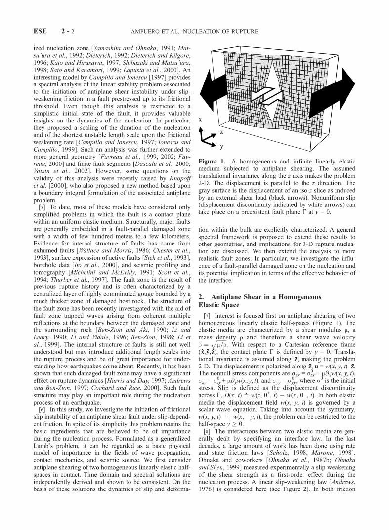
erally dealt by specifying an interface law. In the lastdecades, a large amount of work has been done using rateand state friction laws [Scholz, 1998; Marone, 1998].Ohnaka and coworkers [Ohnaka et al., 1987b; Ohnakaand Shen, 1999] measured experimentally a slip weakeningof the shear strength as a first-order effect during thenucleation process. A linear slip-weakening law [Andrews,1976] is considered here (see Figure 2). In both friction
Figure 1. A homogeneous and infinite linearly elasticmedium subjected to antiplane shearing. The assumedtranslational invariance along the z axis makes the problem2-D. The displacement is parallel to the z direction. Thegray surface is the displacement of an iso-z slice as inducedby an external shear load (black arrows). Nonuniform slip(displacement discontinuity indicated by white arrows) cantake place on a preexistent fault plane � at y = 0.
ESE 2 - 2 AMPUERO ET AL.: NUCLEATION OF RUPTURE
laws, one of the main ingredients is the existence of aninternal length, a feature that we believe controls genericproperties of the nucleation process. However, this willrequire further scrutiny. For the slip-weakening frictionlaw, slip occurs when traction reaches a yield strength ts.As slip evolves, the shear strength decreases linearly downto a residual value, the dynamic strength td. Full strengthdrop, �t = ts � td, is reached for a characteristic slip Dc,an interface length that can be related to surface energy.Without an explicit loading/unloading criterion, the inter-face law is more related to a surface potential than to afriction law besides local monotonic loading. In the remain-ing, the material properties will be assumed uniform alongthe fault.[9] The interface law is intrinsically nonregular due to the
existence of a strength threshold. A regular problem ishowever obtained when the fault is initially at the onset ofsliding, i.e., when initial traction equals the yield strength.Even though such an initial state is more a mathematicalersatz than a realistic physical condition, it allows to studyanalytically the motion induced by a traction perturbationT0(x, t). Such analytical solutions do provide valuableinsights on the physics of the nucleation process. As longas the characteristic slip Dc has not been reached some-where on the fault, the response to a perturbation isgoverned by the following linear problem
@2w
@x2þ @2w
@y2¼ 1
b2@2w
@t2y > 0 ð1Þ
�m@w
@y¼ T0 x; tð Þ þ 2gw y ¼ 0; ð2Þ
with initial conditions w(x, y, 0) =0 and (@w/@t)(x, y, 0) = 0.The slip-weakening rate of the contact interface is defined as
g ¼: �tDc
: ð3Þ
The basic length scale of this problem, a�1, arises from thecompetition between bulk elasticity and slip-weakening rate:
a ¼: 2g=m: ð4Þ
2.1. A Time Domain Solution
[10] Let us consider the response to an impulse loadT0(x, t) = T0 d(x) d(t), where T0 has the dimension of forcetimes time. This elementary solution is to be understood asthe Green’s function of the linear problem. The response tomore general loading, or more general initial conditionslike in the work by Campillo and Ionescu [1997], can beobtained from it by standard numerical convolution.[11] In order to solve the problem, first introduce a virtual
deformation field �(x, y, t) implicitly defined (as by Cam-pillo and Ionescu [1997]) as
@�
@y¼ aw þ @w
@y: ð5Þ
The original problem for w is equivalent to Lamb’s problemfor �:
1
b2@2�
@t2¼ @2�
@x2þ @2�
@y2y > 0 ð6Þ
�m@�
@y¼ T0d xð Þd tð Þ y ¼ 0; ð7Þ
with initial conditions �(x, y, 0) = 0 and (@�/@t)(x, y, 0) = 0.Its solution is
� x; y; tð Þ ¼ T0H t � r=bð Þ
mpffiffiffiffiffiffiffiffiffiffiffiffiffiffiffiffiffiffiffiffit2 � r2=b2
q ; ð8Þ
where H is the Heaviside step function and r2 = x2 + y2. Thedisplacement is found solving equation (5) with equation (8)(see Appendix A), using a Laplace transform with respect toy, carefully taking into account the boundary condition aty = 0. A useful representation of the displacement field interms of the Lamb’s solution is obtained:
w x; y; tð Þ ¼ � x; y; tð Þ þ ae�ayZ 1
y
� x; z; tð Þeaz dz: ð9Þ
Owing to the causality of �, the second term in equation (9)needs to be integrated only within the causality cone, i.e.,from y to Y(x, t) <
ffiffiffiffiffiffiffiffiffiffiffiffiffiffiffiffiffiffib2t2 � x2
pwhen r � bt. As a result, the
solution of the slip-weakening problem also obeys to thecausality principle. Moreover, the motion depends on (x, t)only through
ffiffiffiffiffiffiffiffiffiffiffiffiffiffiffiffiffiffib2t2 � x2
p. When the fault can slip freely,
i.e., a = 0, this second term vanishes and the Lamb’s
Figure 2. Linear slip-weakening interface law. Thetangential shear strength is plotted against the tangentialslip on the fault interface. When the yield strength ts isreached, slip can occur and the shear strength drops linearlyto a dynamic value td. The characteristic distance Dc overwhich the stress drop �t = ts � td takes place is related tothe surface energy.
AMPUERO ET AL.: NUCLEATION OF RUPTURE ESE 2 - 3
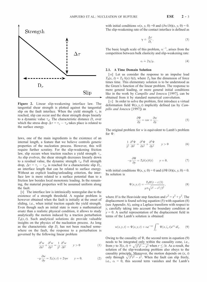
solution is recovered. In the case of slip weakening, a > 0,the displacement left on the wake of the Lamb’s pulse,where jyj Y(x, t), decays exponentially as a function ofthe distance to the fault. The characteristic depth ofpenetration of the induced bulk deformation is a�1 (seeFigure 3).[12] Furthermore, a compact analytical expression for the
slip can be worked out. From equations (8) and (9),
D x; tð Þ ¼ 2T0
mH bt � jxjð Þ 1
pffiffiffiffiffiffiffiffiffiffiffiffiffiffiffiffiffiffiffiffit2 � x2=b2
q8><>:
þ aZ Y x;tð Þ
0
eaz dz
pffiffiffiffiffiffiffiffiffiffiffiffiffiffiffiffiffiffiffiffiffiffiffiffiffiffiffiffiffiffiffiffiffiffiffit2 � x2 þ z2
=b2
q9>=>;: ð10Þ
The last integral can be expressed in terms of the modifiedBessel and Struve functions making use of the relation[Gradshteyn and Ryzhik, 1965, equation 3.387.5]
Z 1
0
ezh
pffiffiffiffiffiffiffiffiffiffiffiffiffi1 � h2
p dh ¼ 1
2L0 þ I0f g zð Þ: ð11Þ
[13] Finally, the slip evolution (Figure 4) is given by
D x; tð Þ ¼ 2T0
mH bt � jxjð Þ 1
pffiffiffiffiffiffiffiffiffiffiffiffiffiffiffiffiffiffiffiffit2 � x2=b2
q264
þ ab2
L0 þ I0f g affiffiffiffiffiffiffiffiffiffiffiffiffiffiffiffiffiffib2t2 � x2
q� �375: ð12Þ
In contrast to the solution of Campillo and Ionescu [1997],this provides an explicit solution in the space and timedomain which is found to agree with the original solution byKnopoff et al. [2000, equation 16] using a boundary integralprocedure.
2.2. A Spectral Solution
[14] Deeper understanding can be obtained by a spectraldomain inspection. Using Fourier transform in x and one-sided Laplace transform in t, with the corresponding trans-formed variables k and s, the displacement is independentlyshown to be (see Appendix B)
w k; y; sð Þ ¼ G k; y; sð ÞT0 k; sð Þ ð13Þ
G k; y; sð Þ ¼ e�ny
m n � að Þ ; ð14Þ
where n k; sð Þ ¼:ffiffiffiffiffiffiffiffiffiffiffiffiffiffiffiffiffiffiffiffiffik2 þ s2=b2
qis defined to have a positive
real part in order to respect radiation conditions out from thefault. Such a spectral approach has been shown in previousstudies by Campillo and Ionescu [1997] and coworkers tobe consistent with direct numerical simulations based onfinite difference methods. Moreover, the spectral Green’sfunction G(k, y, s) can be transformed back to the (x, y, t)domain to check its consistency with the result of Sections2.1 (see Appendix B).[15] In the following, the interest is focused on the
response on the fault itself. The interface Green functionG�, which relates the slip response D(k, s) along the inter-face to a loading perturbation T0(k, s), is defined by
G� k; sð Þ ¼: 2G k; y ¼ 0; sð Þ ¼ 2=mn � a
: ð15Þ
Figure 3. Green’s function for the antiplane shearing along a slip-weakening interface within anhomogeneous linearly elastic medium. The Green’s function is plotted as a function of ay, the normalizeddistance off the fault, and a
ffiffiffiffiffiffiffiffiffiffiffiffiffiffiffiffiffiffib2t2 � x2
p. The inset shows a log plot. Behind the front pulse, the
displacement exhibits an exponential decay out of the fault and an exponential growth with time.
ESE 2 - 4 AMPUERO ET AL.: NUCLEATION OF RUPTURE
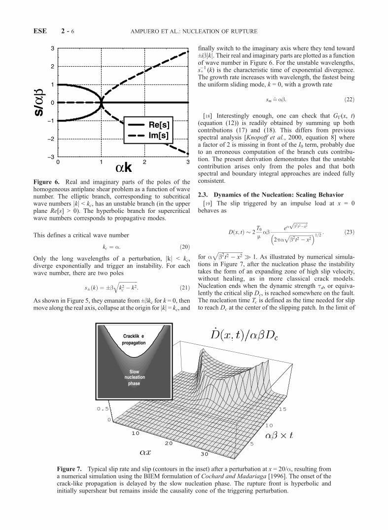
In the complex s plane, G� has poles and branch cutsingularities. Their respective contribution can be isolatedusing a residue technique
G� k; sð Þ ¼ 2=mn þ a
þ 4a=mn2 � a2
¼: Gb k; sð Þ þ Gp k; sð Þ: ð16Þ
[16] The branch cuts contribution is denoted here as Gb,and clearly, the branch cuts of G� are those of n. As shownin Figure 5, they emanate from ±ibjkj and move to ±i1. Asthey lie on the imaginary axis, they only involve stable andpurely propagative (real frequency) modes: the branch cutsdo not contribute to the long-term behavior. Noting that Gb
is identical to G� when a is replaced by �a, the branch cutscontribution is analogous to a slip-strengthening processand therefore is not expected to have an unstable behavior.The back transform of Gb to the (x, t) domain is obtained bychanging a to �a in equation (12) and making use of thesymmetry properties of I0 and L0:
Gb x; tð Þ ¼ 2
mH bt � jxjð Þ 1
pffiffiffiffiffiffiffiffiffiffiffiffiffiffiffiffiffiffib2t2 � x2
p"
þ ab2
L0 � I0f g affiffiffiffiffiffiffiffiffiffiffiffiffiffiffiffiffiffib2t2 � x2
q� �#ð17Þ
Asymptotically, L0 and I0 cancel each other, and the branchcut contribution vanishes for t x/b as O(1/t).[17] Gp in equation (16) stands for the contribution of the
poles. It can be transformed back in the (x, t) domain (seeAppendix B),
Gp x; tð Þ ¼ 2
mH bt � jxjð Þab I0 a
ffiffiffiffiffiffiffiffiffiffiffiffiffiffiffiffiffiffib2t2 � x2
q� �: ð18Þ
For t x/b, this expression diverges as eabt/ffiffiffiffiffiffiffiabt
p.
However, not all the wavelengths have an unstablecontribution. Indeed, the expression of Gp in the (k, t)domain is
Gp k; tð Þ ¼ 2absinh b
ffiffiffiffiffiffiffiffiffiffiffiffiffiffiffiffia2 � k2
pt
� �ffiffiffiffiffiffiffiffiffiffiffiffiffiffiffiffia2 � k2
p jkj � a
¼ 2absin b
ffiffiffiffiffiffiffiffiffiffiffiffiffiffiffiffik2 � a2
pt
� �ffiffiffiffiffiffiffiffiffiffiffiffiffiffiffiffik2 � a2
p jkj � a:
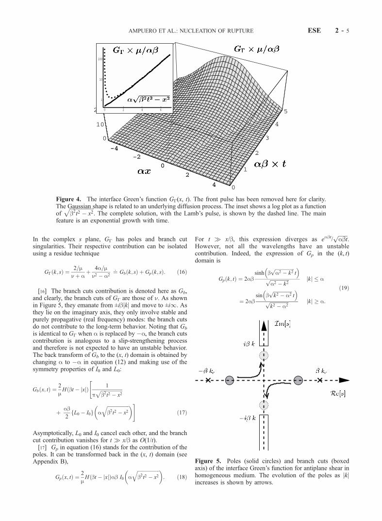
ð19Þ
Figure 4. The interface Green’s function G�(x, t). The front pulse has been removed here for clarity.The Gaussian shape is related to an underlying diffusion process. The inset shows a log plot as a functionof
ffiffiffiffiffiffiffiffiffiffiffiffiffiffiffiffiffiffib2t2 � x2
p. The complete solution, with the Lamb’s pulse, is shown by the dashed line. The main
feature is an exponential growth with time.
Figure 5. Poles (solid circles) and branch cuts (boxedaxis) of the interface Green’s function for antiplane shear inhomogeneous medium. The evolution of the poles as jkjincreases is shown by arrows.
AMPUERO ET AL.: NUCLEATION OF RUPTURE ESE 2 - 5
This defines a critical wave number
kc ¼ a: ð20Þ
Only the long wavelengths of a perturbation, jkj < kc,diverge exponentially and trigger an instability. For eachwave number, there are two poles
s� kð Þ ¼ �bffiffiffiffiffiffiffiffiffiffiffiffiffiffiffik2c � k2
q: ð21Þ
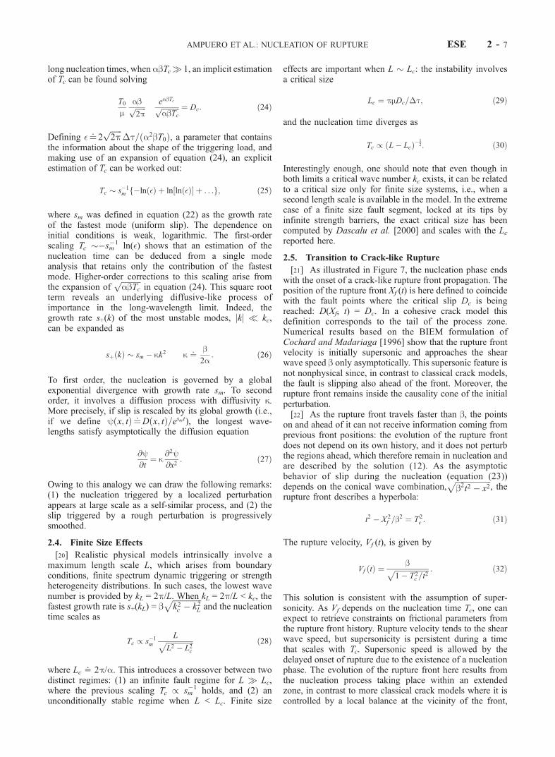
As shown in Figure 5, they emanate from ±bkc for k = 0, thenmove along the real axis, collapse at the origin for jkj = kc, and
finally switch to the imaginary axis where they tend toward±ibjkj. Their real and imaginary parts are plotted as a functionof wave number in Figure 6. For the unstable wavelengths,s+�1 (k) is the characteristic time of exponential divergence.The growth rate increases with wavelength, the fastest beingthe uniform sliding mode, k = 0, with a growth rate
sm ¼: ab: ð22Þ
[18] Interestingly enough, one can check that G�(x, t)(equation (12)) is readily obtained by summing up bothcontributions (17) and (18). This differs from previousspectral analysis [Knopoff et al., 2000, equation 8] wherea factor of 2 is missing in front of the I0 term, probably dueto an erroneous computation of the branch cuts contribu-tion. The present derivation demonstrates that the unstablecontribution arises only from the poles and that bothspectral and boundary integral approaches are indeed fullyconsistent.
2.3. Dynamics of the Nucleation: Scaling Behavior
[19] The slip triggered by an impulse load at x = 0behaves as
D x; tð Þ � 2T0
mab
eaffiffiffiffiffiffiffiffiffiffiffiffib2t2�x2
p
2paffiffiffiffiffiffiffiffiffiffiffiffiffiffiffiffiffiffib2t2 � x2
p� �1=2 : ð23Þ
for affiffiffiffiffiffiffiffiffiffiffiffiffiffiffiffiffiffib2t2 � x2
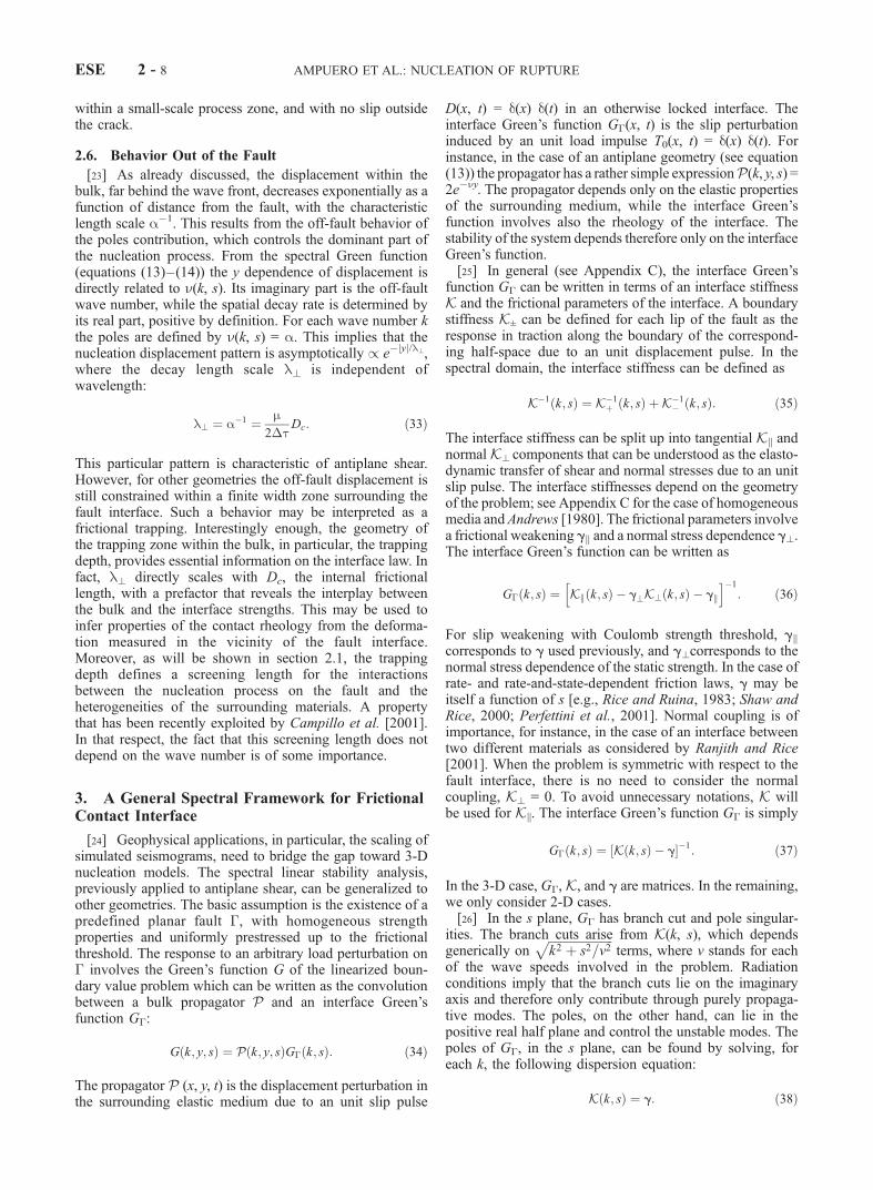
p 1. As illustrated by numerical simula-
tions in Figure 7, after the nucleation phase the instabilitytakes the form of an expanding zone of high slip velocity,without healing, as in more classical crack models.Nucleation ends when the dynamic strength td, or equiva-lently the critical slip Dc, is reached somewhere on the fault.The nucleation time Tc is defined as the time needed for slipto reach Dc at the center of the slipping patch. In the limit of
Figure 6. Real and imaginary parts of the poles of thehomogeneous antiplane shear problem as a function of wavenumber. The elliptic branch, corresponding to subcriticalwave numbers jkj < kc, has an unstable branch (in the upperplane Re[s] > 0). The hyperbolic branch for supercriticalwave numbers corresponds to propagative modes.
Figure 7. Typical slip rate and slip (contours in the inset) after a perturbation at x = 20/a, resulting froma numerical simulation using the BIEM formulation of Cochard and Madariaga [1996]. The onset of thecrack-like propagation is delayed by the slow nucleation phase. The rupture front is hyperbolic andinitially supershear but remains inside the causality cone of the triggering perturbation.
ESE 2 - 6 AMPUERO ET AL.: NUCLEATION OF RUPTURE
long nucleation times, whenabTc 1, an implicit estimationof Tc can be found solving
T0
mabffiffiffiffiffiffi2p
p eabTcffiffiffiffiffiffiffiffiffiffiabTc
p ¼ Dc: ð24Þ
Defining �¼: 2ffiffiffiffiffiffi2p
p�t= a2bT0ð Þ, a parameter that contains
the information about the shape of the triggering load, andmaking use of an expansion of equation (24), an explicitestimation of Tc can be worked out:
Tc � s�1m �ln �ð Þ þ ln ln �ð Þ½ � þ . . .f g; ð25Þ
where sm was defined in equation (22) as the growth rateof the fastest mode (uniform slip). The dependence oninitial conditions is weak, logarithmic. The first-orderscaling Tc ��sm
�1 ln(�) shows that an estimation of thenucleation time can be deduced from a single modeanalysis that retains only the contribution of the fastestmode. Higher-order corrections to this scaling arise fromthe expansion of
ffiffiffiffiffiffiffiffiffiffiabTc
pin equation (24). This square root
term reveals an underlying diffusive-like process ofimportance in the long-wavelength limit. Indeed, thegrowth rate s+(k) of the most unstable modes, jkj kc,can be expanded as
sþ kð Þ � sm � kk2 k ¼: b2a
: ð26Þ
To first order, the nucleation is governed by a globalexponential divergence with growth rate sm. To secondorder, it involves a diffusion process with diffusivity k.More precisely, if slip is rescaled by its global growth (i.e.,if we define y x; tð Þ ¼: D x; tð Þ=esmt), the longest wave-lengths satisfy asymptotically the diffusion equation
@y@t
¼ k@2y@x2
: ð27Þ
Owing to this analogy we can draw the following remarks:(1) the nucleation triggered by a localized perturbationappears at large scale as a self-similar process, and (2) theslip triggered by a rough perturbation is progressivelysmoothed.
2.4. Finite Size Effects
[20] Realistic physical models intrinsically involve amaximum length scale L, which arises from boundaryconditions, finite spectrum dynamic triggering or strengthheterogeneity distributions. In such cases, the lowest wavenumber is provided by kL = 2p/L. When kL = 2p/L < kc, thefastest growth rate is s+(kL) = b
ffiffiffiffiffiffiffiffiffiffiffiffiffiffiffik2c � k2L
pand the nucleation
time scales as
Tc / s�1m
LffiffiffiffiffiffiffiffiffiffiffiffiffiffiffiffiL2 � L2c
p ð28Þ
where Lc < 2p/a. This introduces a crossover between twodistinct regimes: (1) an infinite fault regime for L Lc,where the previous scaling Tc / sm
�1 holds, and (2) anunconditionally stable regime when L < Lc. Finite size
effects are important when L � Lc: the instability involvesa critical size
Lc ¼ pmDc=�t; ð29Þ
and the nucleation time diverges as
Tc / L � Lcð Þ�12: ð30Þ
Interestingly enough, one should note that even though inboth limits a critical wave number kc exists, it can be relatedto a critical size only for finite size systems, i.e., when asecond length scale is available in the model. In the extremecase of a finite size fault segment, locked at its tips byinfinite strength barriers, the exact critical size has beencomputed by Dascalu et al. [2000] and scales with the Lcreported here.
2.5. Transition to Crack-like Rupture
[21] As illustrated in Figure 7, the nucleation phase endswith the onset of a crack-like rupture front propagation. Theposition of the rupture front Xf (t) is here defined to coincidewith the fault points where the critical slip Dc is beingreached: D(Xf, t) = Dc. In a cohesive crack model thisdefinition corresponds to the tail of the process zone.Numerical results based on the BIEM formulation ofCochard and Madariaga [1996] show that the rupture frontvelocity is initially supersonic and approaches the shearwave speed b only asymptotically. This supersonic feature isnot nonphysical since, in contrast to classical crack models,the fault is slipping also ahead of the front. Moreover, therupture front remains inside the causality cone of the initialperturbation.[22] As the rupture front travels faster than b, the points
on and ahead of it can not receive information coming fromprevious front positions: the evolution of the rupture frontdoes not depend on its own history, and it does not perturbthe regions ahead, which therefore remain in nucleation andare described by the solution (12). As the asymptoticbehavior of slip during the nucleation (equation (23))depends on the conical wave combination,
ffiffiffiffiffiffiffiffiffiffiffiffiffiffiffiffiffiffib2t2 � x2
p, the
rupture front describes a hyperbola:
t2 � X 2f =b
2 ¼ T2c : ð31Þ
The rupture velocity, Vf (t), is given by
Vf tð Þ ¼ bffiffiffiffiffiffiffiffiffiffiffiffiffiffiffiffiffiffiffiffi1 � T 2
c =t2
p : ð32Þ
This solution is consistent with the assumption of super-sonicity. As Vf depends on the nucleation time Tc, one canexpect to retrieve constraints on frictional parameters fromthe rupture front history. Rupture velocity tends to the shearwave speed, but supersonicity is persistent during a timethat scales with Tc. Supersonic speed is allowed by thedelayed onset of rupture due to the existence of a nucleationphase. The evolution of the rupture front here results fromthe nucleation process taking place within an extendedzone, in contrast to more classical crack models where it iscontrolled by a local balance at the vicinity of the front,
AMPUERO ET AL.: NUCLEATION OF RUPTURE ESE 2 - 7
within a small-scale process zone, and with no slip outsidethe crack.
2.6. Behavior Out of the Fault
[23] As already discussed, the displacement within thebulk, far behind the wave front, decreases exponentially as afunction of distance from the fault, with the characteristiclength scale a�1. This results from the off-fault behavior ofthe poles contribution, which controls the dominant part ofthe nucleation process. From the spectral Green function(equations (13)–(14)) the y dependence of displacement isdirectly related to n(k, s). Its imaginary part is the off-faultwave number, while the spatial decay rate is determined byits real part, positive by definition. For each wave number kthe poles are defined by n(k, s) = a. This implies that thenucleation displacement pattern is asymptotically / e�jyj/l?,where the decay length scale l? is independent ofwavelength:
l? ¼ a�1 ¼ m2�t
Dc: ð33Þ
This particular pattern is characteristic of antiplane shear.However, for other geometries the off-fault displacement isstill constrained within a finite width zone surrounding thefault interface. Such a behavior may be interpreted as africtional trapping. Interestingly enough, the geometry ofthe trapping zone within the bulk, in particular, the trappingdepth, provides essential information on the interface law. Infact, l? directly scales with Dc, the internal frictionallength, with a prefactor that reveals the interplay betweenthe bulk and the interface strengths. This may be used toinfer properties of the contact rheology from the deforma-tion measured in the vicinity of the fault interface.Moreover, as will be shown in section 2.1, the trappingdepth defines a screening length for the interactionsbetween the nucleation process on the fault and theheterogeneities of the surrounding materials. A propertythat has been recently exploited by Campillo et al. [2001].In that respect, the fact that this screening length does notdepend on the wave number is of some importance.
3. A General Spectral Framework for FrictionalContact Interface
[24] Geophysical applications, in particular, the scaling ofsimulated seismograms, need to bridge the gap toward 3-Dnucleation models. The spectral linear stability analysis,previously applied to antiplane shear, can be generalized toother geometries. The basic assumption is the existence of apredefined planar fault �, with homogeneous strengthproperties and uniformly prestressed up to the frictionalthreshold. The response to an arbitrary load perturbation on� involves the Green’s function G of the linearized boun-dary value problem which can be written as the convolutionbetween a bulk propagator P and an interface Green’sfunction G�:
G k; y; sð Þ ¼ P k; y; sð ÞG� k; sð Þ: ð34Þ
The propagator P (x, y, t) is the displacement perturbation inthe surrounding elastic medium due to an unit slip pulse
D(x, t) = d(x) d(t) in an otherwise locked interface. Theinterface Green’s function G�(x, t) is the slip perturbationinduced by an unit load impulse T0(x, t) = d(x) d(t). Forinstance, in the case of an antiplane geometry (see equation(13)) the propagator has a rather simple expressionP(k, y, s) =2e�ny. The propagator depends only on the elastic propertiesof the surrounding medium, while the interface Green’sfunction involves also the rheology of the interface. Thestability of the system depends therefore only on the interfaceGreen’s function.[25] In general (see Appendix C), the interface Green’s
function G� can be written in terms of an interface stiffnessK and the frictional parameters of the interface. A boundarystiffness K± can be defined for each lip of the fault as theresponse in traction along the boundary of the correspond-ing half-space due to an unit displacement pulse. In thespectral domain, the interface stiffness can be defined as
K�1 k; sð Þ ¼ K�1þ k; sð Þ þ K�1
� k; sð Þ: ð35Þ
The interface stiffness can be split up into tangential Kk andnormal K? components that can be understood as the elasto-dynamic transfer of shear and normal stresses due to an unitslip pulse. The interface stiffnesses depend on the geometryof the problem; see Appendix C for the case of homogeneousmedia andAndrews [1980]. The frictional parameters involvea frictional weakening gk and a normal stress dependence g?.The interface Green’s function can be written as
G� k; sð Þ ¼ Kk k; sð Þ � g?K? k; sð Þ � gk
h i�1
: ð36Þ
For slip weakening with Coulomb strength threshold, gkcorresponds to g used previously, and g?corresponds to thenormal stress dependence of the static strength. In the case ofrate- and rate-and-state-dependent friction laws, g may beitself a function of s [e.g., Rice and Ruina, 1983; Shaw andRice, 2000; Perfettini et al., 2001]. Normal coupling is ofimportance, for instance, in the case of an interface betweentwo different materials as considered by Ranjith and Rice[2001]. When the problem is symmetric with respect to thefault interface, there is no need to consider the normalcoupling, K? = 0. To avoid unnecessary notations, K willbe used for Kk. The interface Green’s function G� is simply
G� k; sð Þ ¼ K k; sð Þ � g½ ��1: ð37Þ
In the 3-D case, G�, K, and g are matrices. In the remaining,we only consider 2-D cases.[26] In the s plane, G� has branch cut and pole singular-
ities. The branch cuts arise from K(k, s), which dependsgenerically on
ffiffiffiffiffiffiffiffiffiffiffiffiffiffiffiffiffiffiffiffiffik2 þ s2=v2
pterms, where v stands for each
of the wave speeds involved in the problem. Radiationconditions imply that the branch cuts lie on the imaginaryaxis and therefore only contribute through purely propaga-tive modes. The poles, on the other hand, can lie in thepositive real half plane and control the unstable modes. Thepoles of G�, in the s plane, can be found by solving, foreach k, the following dispersion equation:
K k; sð Þ ¼ g: ð38Þ
ESE 2 - 8 AMPUERO ET AL.: NUCLEATION OF RUPTURE
The instability is generally dominated by the longest wave-lengths available in the system. An example of instabilitydominated by some selected finite length scale can be foundin the multipulse instability studied by Lapusta and Rice[1998] using a specific enhanced weakening rate-and-statelaw. Quite generally, depending on the parameter js/vkj, twoextreme regimes can be identified.[27] For js/vkj 1, i.e., the high-frequency and long-
wavelength limit, an expansion to second order in jvk/sjgives the fast limit of K:
K k; sð Þ � C sð Þs þ � sð Þk2: ð39Þ
The first term can be interpreted as a local radiation damp-ing, while the second term can be related to a Laplacianterm in space. The nucleation time, in the case of an infinitefault system, scales with the growth rate sm of the homoge-neous mode, the largest root of
C sð Þs ¼ g;
the maximum nucleation growth rate results from thecompetition between the radiation damping due to the bulkmaterial and the slip-weakening rate of the interface friction.It is controlled by a dynamic property of the interfacestiffness, more precisely its radiation damping limit. Forhomogeneous media the radiation damping coefficient isC(s) = m/2b and the scaling of the fastest growth rate givenby equation (22) still holds, even in three dimensions. Thediffusion behavior of the longest wavelengths, as illustratedfor the antiplane case (equation (26)), can be shown to resultfrom the second leading term in the fast limit expansion. Inparticular, for in-plane shear the P-SV diffusivity k is greaterthan the SH one. In the 3-D case the diffusion limit isanisotropic and leads to a macroscopic elliptical shapedslipping patch, with long axis parallel to slip direction, asalso seen in numerical experiments [Favreau, 2000].[28] For js/vkj 1, an expansion up to second order in
js/vkj leads to the slow limit of the interface stiffness:
K k; sð Þ � K kð Þ þ M kð Þs2: ð40Þ
To first order, the static stiffness K(k) is recovered. Tosecond order, each spectral component of slip can be treatedas a spring-block system of stiffness K(k) and mass M(k). Inantiplane shear the mass is found to beM(k) = r/4jkj and canbe physically related to the mass mobilized by the staticmode of wave number k, which induces a deformation intothe bulk over a distance jkj�1. Similar scalings of the faultmass have been used by Roy and Marone [1996] to studythe effects of inertia on nucleation, with single degree offreedom systems. For interface laws with an intrinsic lengthscale, such as the slip-weakening and rate-and-state laws,short wavelengths are stable, and a critical wave number kcdefines the boundary between stable and unstable domainsof the spectrum. For velocity-weakening laws, with nointrinsic length scale, a similar analysis shows that for high-velocity weakening rates gv , e.g., gv > m/2b in antiplane, allthe wavelengths are unstable. For slip-weakening laws, s = 0at the stability transition and kc is defined as the root of
K kcð Þ ¼ g:
The critical wave number results here from the competitionbetween two mechanical responses: the static elasticity of thematerial surrounding the fault; the slip-weakening rate of thefriction that characterized the fault interface. In contrast tosm, kc is controlled by the static part of the interface stiffness.Moreover, the spring-mass representation is valid close to kc.In particular, for a finite size system close to the critical sizeL � Lc this leads to
sm �
ffiffiffiffiffiffiffiffiffiffiffiffiffiffiffiffiffiffiffiffig � K kLð ÞM kLð Þ
s/
ffiffiffiffiffiffiffiffiffiffiffiffiffiL � Lc
p: ð41Þ
The exponent � 12in the scaling equation (30) of the
nucleation time close to the critical size is thus related to themass like nature of the leading inertial term in the slowlimit.[29] The slow and fast limit, which are shown to be of
primary importance during the dynamic nucleation process,are lacking in the so-called quasi-dynamic approximationwhich only retains the radiation damping and static con-tributions, K(k, s) � ms/2b + K(k). This approximationrespects the slow and fast limits only to first order. Thefirst-order properties of nucleation, sm and kc, will becorrectly described but not the second-order effects. Toexplain the diffusion-like scaling of slip and the finite sizedynamic effects, inertial effects must be correctly taken intoaccount, even in the slow limit.
4. Simple Antiplane Models of a Fault Zone
[30] As a first step toward more realistic models of thefault zone, interest is focused on antiplane shearing of twoelastic media with variations of the shear velocity b in thedirection normal to the fault plane, over a characteristiclength scale h. These variations represent a fault-paralleldamaged zone of lowered velocity that results from pre-vious rupture history or a localized geological deformation.The geometrical and mechanical properties of the damagedzone are assumed to be stable during the nucleation process.For simplicity, the density is that of the surrounding rock, r,but the elastic shear modulus is ^y-dependent. Far away fromthe fault the shear modulus of the intact rock is m, whereasin the immediate vicinity of the fault it is md = (1 � �)m,where 0 < � < 1 defines the damage level close to the fault.The scale of the fault-parallel damaged zone is given by thecharacteristic length h of the shear modulus distribution. Onthe fault plane itself, the interface law is still a linear slip-weakening law with weakening rate g. These fault zonemodels are therefore defined by four parameters. The twofirst parameters characterize the undamaged referencemodel: b, the shear wave velocity of the undamaged elasticmaterial; l? = a�1 = m/2g, the trapping depth of theundamaged fault interface. The two remaining parameterscharacterize the internal fault zone: �, a mechanical prop-erty defined as the maximum damage within the fault zone;h, a geometrical property defined as the characteristic widthof the damaged fault zone.[31] In the first fault zone model (FZ1) (Figure 8) the
shear modulus has a smooth distribution
m yð Þ ¼ m þ md � mð Þe�jyj=h: ð42Þ
AMPUERO ET AL.: NUCLEATION OF RUPTURE ESE 2 - 9

In the second fault zone model (FZ2) (Figure 9) a layereddistribution of the shear modulus is assumed:
m yð Þ ¼ md : jyj � h
m : jyj > h:
�ð43Þ
The interface stiffness and the bulk propagator for FZ1 arederived in Appendix D:
K k; sð Þ ¼ 1
2md n þ �
h
F 0 a; b; c; �ð ÞF a; b; c; �ð Þ
� �ð44Þ
P k; y; sð Þ ¼ 1
2sgn yð Þe�njyj F a; b; c; �e�jyj=h
F a; b; c; �ð Þ ; ð45Þ
where F is the hypergeometrical function, F 0 is its derivativewith respect to its last argument and
n k; sð Þ ¼ffiffiffiffiffiffiffiffiffiffiffiffiffiffiffiffiffiffiffiffiffik2 þ s2=b2
q;
a k; sð Þ ¼ 12
1 þ 2hn þffiffiffiffiffiffiffiffiffiffiffiffiffiffiffiffiffiffiffiffiffiffi1 þ 2hkð Þ2
q� �;
b k; sð Þ ¼ 12
1 þ 2hn �ffiffiffiffiffiffiffiffiffiffiffiffiffiffiffiffiffiffiffiffiffiffi1 þ 2hkð Þ2
q� �;
c k; sð Þ ¼ 1 þ 2hn:
ð46Þ
The interface stiffness and the bulk propagator for FZ2 can becomputed by basic elastodynamics in spectral domain:
K k; sð Þ ¼ 12mdnd cotanh hnd þ ð Þ
P k; y; sð Þ ¼sinh nd h�yð Þþ½ �2 sinh hndþð Þ : jyj < h
sinh2 sinh hndþð Þ e
�n y�hð Þ : jyj > h
8><>:
ð47Þ
where
nd k; sð Þ ¼ffiffiffiffiffiffiffiffiffiffiffiffiffiffiffiffiffiffiffiffiffik2 þ s2=b2d
qð48Þ
k; sð Þ ¼ arctanhmdndmn
� �: ð49Þ
The stiffness of the interface between two elastic slabs ofwidth h driven by imposed displacements at their externalsurface, a case relevant for laboratory simple shear tests, canbe obtained as an end-member of FZ2 when the outermostmedium is rigid, m/md ! 1. The corresponding interfacestiffness is K k; sð Þ ¼ 1
2mdnd cotanh (ndh).
4.1. Stability Analysis and Nucleation
[32] Interest is focused on the asymptotic behavior of thenucleation for both models of fault zone. As previouslyshown, asymptotic properties are fully characterized by theunstable poles of the interface Green’s function. Numeri-cally, its is found that the evolution of these poles, as afunction of wave number, can be fitted for both FZ1 and FZ2models by an ellipse, a quite generic scaling for the antiplaneFigure 8. Model of smoothly damaged fault zone FZ1.
Figure 9. Model of layered damaged fault zone FZ2.
ESE 2 - 10 AMPUERO ET AL.: NUCLEATION OF RUPTURE

geometry. Such a scaling is illustrated in Figure 10 and is arobust feature of both models, at least within a reasonablerange of damage, 0 < � < 0.9. The ellipse is completelydetermined by two properties: the maximum growth rate ofthe nucleation instability, sm(h,�), and the critical wavenumber, kc(h, �), that bounds the unstable spectrum:
s2þs2m h;�ð Þ þ k2
k2c h;�ð Þ ¼ 1 ð50Þ
for jkj � kc(h, �). Both properties are obtained numericallyby solving the dispersion equation (37) in the fast and slowlimits, respectively. They fully characterize the asymptoticbehavior of fault slip during nucleation.[33] The dependence of nucleation on the properties of the
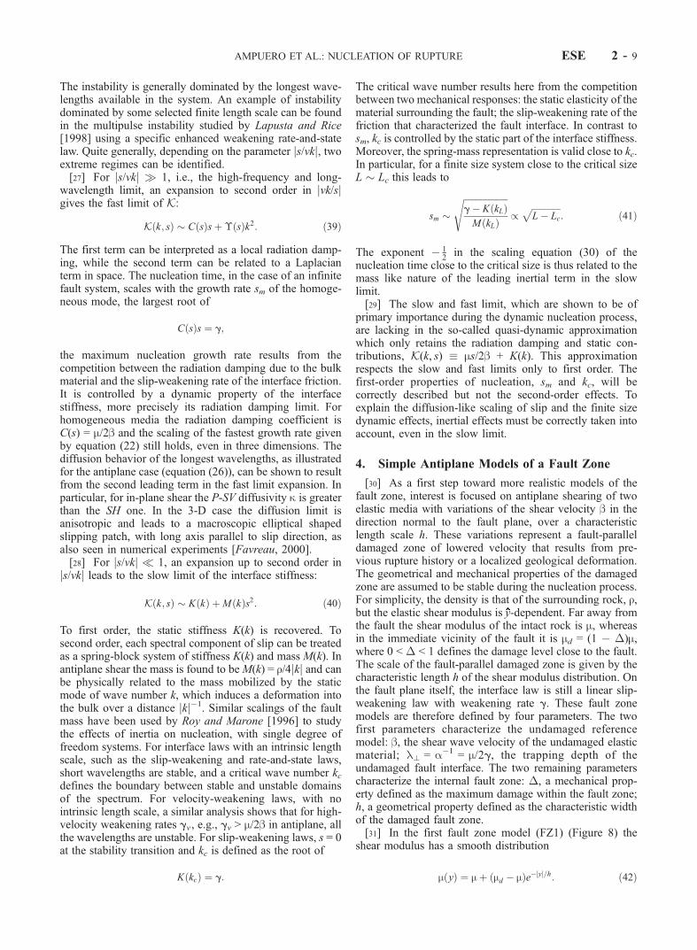
fault zone can be understood by the scaling of sm(h, �) andkc(h,�). Such a scaling is shown for models FZ1 and FZ2 inFigure 11 as a function of h, for a range of damage relevantfor the core zone and the outer zone of a fault,� = 10–90%.As the trapping depth l? = a�1 is the only length scalepresent in the undamaged reference model, the nucleation inboth fault zone models depends on the ratio ah between thecharacteristic width of the damage distribution and thisreference trapping depth. In Figure 11 the governing proper-ties of nucleation are scaled in order to show the continuouscrossover between two limiting regimes. For the selecteddamage levels the range of ah has been restricted to thetransition regime. When ah 1, the nucleation process doesnot depend on the existing damaged fault zone and scales asthe previous homogeneous case with the properties of theintact host rock: kc(h,�) ! kc = a and sm(h,�) ! sm = ab.When ah 1, the nucleation becomes governed by theproperties of the damaged material in the immediate vicinityof the fault: kc(h, �) ! kc
d = ad and sm(h, �) ! smd = adbd,
where ad�1 = md/2g and bd ¼
ffiffiffiffiffiffiffiffiffimd=r
pare the trapping depth
and the shear wave speed in a model of nucleation betweentwo homogeneous damaged half-spaces. In this regime, the
nucleation is faster and the unstable spectrum is broader thanwhat would have been estimated using the intact host rockelastic properties alone. Furthermore, the nucleation is nolonger dependent on the geometry of the fault zone but onlyon its mechanical properties. Between these two regimes,there is a nontrivial dependence on the thickness of the faultzone. The main difference between models FZ1 and FZ2appear in this crossover regime: while the crossover of modelFZ1 is weakly dependent on the damage level of the faultzone, model FZ2 shows a more acute sensitivity on damage.[34] The crossover for kc(h, �) allows to define a critical
fault zone thickness h* such that kc(h*, �) = (kc + kcd)/2. A
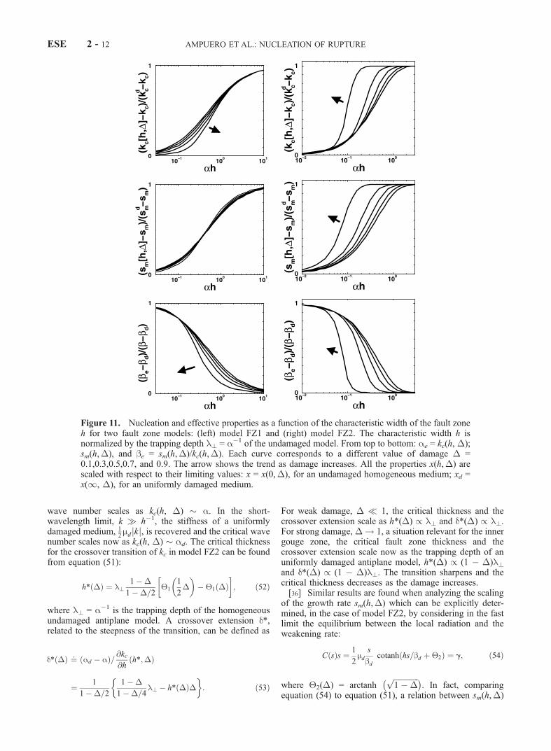
similar quantity can be defined for the crossover of sm(h,�). In model FZ1 the critical thickness is found to remain ofthe same order than l?, even for strong damage. On theother hand, in the fault zone model FZ2 the critical thick-ness depends on the damage: h* decreases as � increases,while the transition becomes stiffer and stiffer, as shown inFigure 12 up to extreme values of damage. Such a differ-ence may be related to the different smoothness assump-tions in the damage distribution of each model. These twomodels can be regarded as extreme cases for the damagedistribution and provide a glimpse of the complexity thatcan be expected from realistic fault zones.[35] In the case of model FZ2, scalings can be analyzed
in closed form due to the simpler structure of the interfaceGreen’s function and of the propagator. The critical wavenumber kc(h, �) can be explicitly found by considering inthe slow limit the equilibrium between the static stiffnessand the weakening rate
K kð Þ ¼ 1
2md jkj cotanh hjkj þ 1ð Þ ¼ g; ð51Þ
where 1(�) = arctanh (1 � �). In the long-wavelengthlimit, k h�11, the static stiffness of an homogeneousundamaged medium, 1
2mjkj, is recovered and the critical
Figure 10. (a) The unstable branch for FZ1, i.e., the positive real valued poles s+(k) of its interfaceGreen’s function G�(k, s), as a function of wave number k, for � = 0.5 and for different values of h. Theinset shows s+
2 as a function of k2, for ah = 0.01,0.1,1,10 and 100. The overall shape is elliptical. (b)Same than inset in Figure 10a but for FZ2, with ah = 0.01,0.1,0.3,0.5,1, and 10.
AMPUERO ET AL.: NUCLEATION OF RUPTURE ESE 2 - 11
wave number scales as kc(h, �) � a. In the short-wavelength limit, k h�1, the stiffness of a uniformlydamaged medium, 1
2mdjkj, is recovered and the critical wave
number scales now as kc(h, �) � ad. The critical thicknessfor the crossover transition of kc in model FZ2 can be foundfrom equation (51):
h* �ð Þ ¼ l?1 � �
1 � �=21
1
2�
� �� 1 �ð Þ
� �; ð52Þ
where l? = a�1 is the trapping depth of the homogeneousundamaged antiplane model. A crossover extension d*,related to the steepness of the transition, can be defined as
d* �ð Þ ¼: ad � að Þ= @kc@h
h*;�ð Þ
¼ 1
1 � �=2
1 � �
1 � �=4l? � h* �ð Þ�
� : ð53Þ
For weak damage, � 1, the critical thickness and thecrossover extension scale as h*(�) / l? and d*(�) / l?.For strong damage, � ! 1, a situation relevant for the innergouge zone, the critical fault zone thickness and thecrossover extension scale now as the trapping depth of anuniformly damaged antiplane model, h*(�) / (1 � �)l?and d*(�) / (1 � �)l?. The transition sharpens and thecritical thickness decreases as the damage increases.[36] Similar results are found when analyzing the scaling
of the growth rate sm(h,�) which can be explicitly deter-mined, in the case of model FZ2, by considering in the fastlimit the equilibrium between the local radiation and theweakening rate:
C sð Þs ¼ 1
2md
s
bdcotanh hs=bd þ 2ð Þ ¼ g; ð54Þ
where 2(�) = arctanh ffiffiffiffiffiffiffiffiffiffiffiffiffi
1 � �p
. In fact, comparingequation (54) to equation (51), a relation between sm(h,�)
Figure 11. Nucleation and effective properties as a function of the characteristic width of the fault zoneh for two fault zone models: (left) model FZ1 and (right) model FZ2. The characteristic width h isnormalized by the trapping depth l? = a�1 of the undamaged model. From top to bottom: ae = kc(h, �);sm(h,�), and be = sm(h,�)/kc(h,�). Each curve corresponds to a different value of damage � =0.1,0.3,0.5,0.7, and 0.9. The arrow shows the trend as damage increases. All the properties x(h,�) arescaled with respect to their limiting values: x = x(0,�), for an undamaged homogeneous medium; xd =x(1, �), for an uniformly damaged medium.
ESE 2 - 12 AMPUERO ET AL.: NUCLEATION OF RUPTURE
and kc(h,�) can be found
sm h;�ð Þ ¼ffiffiffiffiffiffiffiffiffiffiffiffiffi1 � �
pbkc h; 1 �
ffiffiffiffiffiffiffiffiffiffiffiffiffi1 � �
p� �ð55Þ
that relates also the critical thickness and the crossoverextension of kc(h, �) and sm(h, �). The scalings found forthe critical wave number in the weak and strong damagelimits hold therefore also for the maximum growth rate.Now sm(h, �) and kc(h, �) being extremal properties of theunstable spectrum, the whole unstable branch, 0 < jkj < kc(h,�), is expected to follow the same trends.
4.2. An Effective Medium Approach
[37] As already discussed, the scaling of the unstablepoles as a function of the wave number is quite generic ofantiplane geometry. It follows an ellipse that is defined bytwo parameters: the maximum growth rate sm(h, �) and thecritical wave number kc(h, �). This ellipse fully character-izes the asymptotic behavior of the slip, for jkj < kc(h, �),during the nucleation. This suggest that an effective homo-geneous model with the same asymptotic nucleation behav-ior than a damaged fault zone model, characterized by thefour parameters (a, b, �, h), may be simply defined by twoparameters ae and be such that:
kc h;�ð Þ ¼ ae ð56Þ
sm h;�ð Þ ¼ beae: ð57Þ
These effective parameters are determined on the basis ofthe scalings of kc and sm found for homogeneous models.
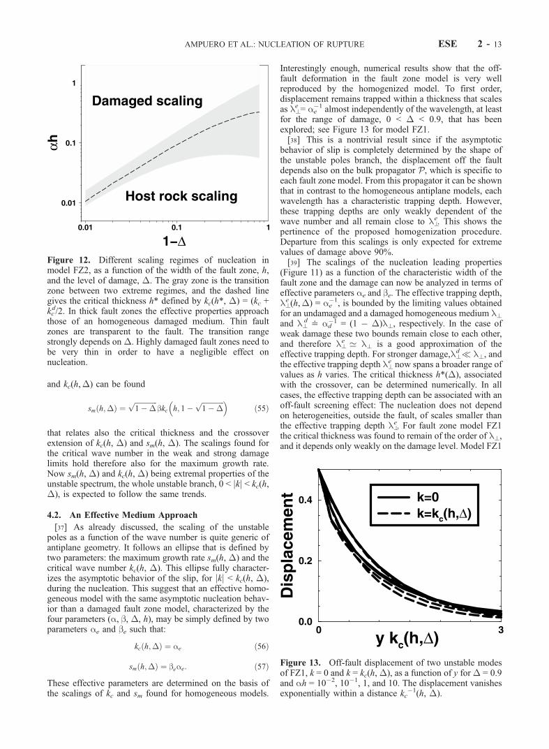
Interestingly enough, numerical results show that the off-fault deformation in the fault zone model is very wellreproduced by the homogenized model. To first order,displacement remains trapped within a thickness that scalesas l?
e = ae�1 almost independently of the wavelength, at least
for the range of damage, 0 < � < 0.9, that has beenexplored; see Figure 13 for model FZ1.[38] This is a nontrivial result since if the asymptotic
behavior of slip is completely determined by the shape ofthe unstable poles branch, the displacement off the faultdepends also on the bulk propagator P, which is specific toeach fault zone model. From this propagator it can be shownthat in contrast to the homogeneous antiplane models, eachwavelength has a characteristic trapping depth. However,these trapping depths are only weakly dependent of thewave number and all remain close to l?
e. This shows thepertinence of the proposed homogenization procedure.Departure from this scalings is only expected for extremevalues of damage above 90%.[39] The scalings of the nucleation leading properties
(Figure 11) as a function of the characteristic width of thefault zone and the damage can now be analyzed in terms ofeffective parameters ae and be. The effective trapping depth,l?e (h,�) = ae
�1, is bounded by the limiting values obtainedfor an undamaged and a damaged homogeneous medium l?and l?
d < ad�1 = (1 � �)l?, respectively. In the case of
weak damage these two bounds remain close to each other,and therefore l?
e ’ l? is a good approximation of theeffective trapping depth. For stronger damage,l?
d l?, andthe effective trapping depth l?
e now spans a broader range ofvalues as h varies. The critical thickness h*(�), associatedwith the crossover, can be determined numerically. In allcases, the effective trapping depth can be associated with anoff-fault screening effect: The nucleation does not dependon heterogeneities, outside the fault, of scales smaller thanthe effective trapping depth l?
e. For fault zone model FZ1the critical thickness was found to remain of the order of l?,and it depends only weakly on the damage level. Model FZ1
Figure 12. Different scaling regimes of nucleation inmodel FZ2, as a function of the width of the fault zone, h,and the level of damage, �. The gray zone is the transitionzone between two extreme regimes, and the dashed linegives the critical thickness h* defined by kc(h*, �) = (kc +kcd/2. In thick fault zones the effective properties approach
those of an homogeneous damaged medium. Thin faultzones are transparent to the fault. The transition rangestrongly depends on �. Highly damaged fault zones need tobe very thin in order to have a negligible effect onnucleation.
Figure 13. Off-fault displacement of two unstable modesof FZ1, k = 0 and k = kc(h,�), as a function of y for� = 0.9and ah = 10�2, 10�1, 1, and 10. The displacement vanishesexponentially within a distance kc
�1(h, �).
AMPUERO ET AL.: NUCLEATION OF RUPTURE ESE 2 - 13

is therefore characterized by a single off-fault screeninglength ’ l?. This is in contrast to the layered fault zonemodel FZ2 for which the critical thickness of the crossoverexhibits a stronger sensitivity on the damage. In this case(see Figure 12), as the damage increases, the critical thick-ness decreases and the transition becomes stiffer: Thenucleation becomes sensitive to smaller and smaller scalesof heterogeneities outside the fault. Frictional trapping istherefore an important phenomenon that controls the nucle-ation of damaged fault zones. Frictional trapping impliesthat all the modes see the same effective medium and thatarbitrarily long wavelengths can be sensitive to the existenceof the fault zone for a thick enough fault zone.
5. Discussion
[40] In general [Chester et al., 1993], a fault zone consistsof three structures: a central layer of highly comminutedgouge or ultracataclasite, centimeters to decimeters thick,within a core of foliated cataclasites, 30–100 m thick,embedded in turn in an order of magnitude thicker zoneof damaged rock, containing abundant microfractures. Theborehole measures across the active Nojima fault, at a depthof about 630 m, showed the presence of a 30-m-thick layerof altered and deformed granodiorites surrounding a 20-cm-thick gouge layer [Ito et al., 2000]. Inside the gouge zone,high to extreme damage, which can be considered as almostuniform, is expected. Strong and sharp variations of phys-ical properties can be expected at the boundary between thegouge and the surrounding core zone. The core zone in turncan reach damage levels of 50%. In the outer zone, damagedecreases continuously with the distance to the fault. How-ever, the boundary between the core and the outer zones isdifficult to define. Trapped wave inversions usually assumea homogeneous core zone layer, while borehole data show arather smooth distribution of shear wave velocities. Themodel FZ2 would be appropriate for the gouge, while modelFZ1 is more appropriate for the outer zone. Until moreprecise data are gathered for the core zone, we can not ruleout a priori one model or the other.[41] Figure 12 summarizes the different nucleation
behaviors in model FZ2 as a function of the two (geo-metrical and mechanical) properties defining the faultzone, h and �. To assess the effect of each fault zonestructure on the nucleation process, it is important toestimate the ratio h/l? = ah between the trapping depthassociated to the host rock and the thickness of thestructure considered.[42] As working examples, we take the Nojima fault,
which ruptured during the 1995 Kobe earthquake, and theSan Andreas system. From waveform inversion of near-field strong motion seismograms, Ide and Takeo [1997]estimated a 5-MPa stress drop in the hypocentral region ofthe Kobe earthquake, and Bouchon [1997] obtained �t ’20–100 MPa for major Californian earthquakes. As a ruleof thumb, the ratio between the reference trapping depth andthe critical slip l?/Dc is of the same order than m/�t and istypically in the range 103–104. For instance, taking m � 43GPa, as given by the regional velocity model at thehypocentral depth of the Kobe earthquake, the followingscaling for the trapping depth associated with the host rockof Nojima fault is found: l? � 4 � 103Dc.
[43] The value of Dc for real earthquakes is still a matterof discussion. At the laboratory scale it ranges from tens ofmicrometers for precut surfaces or simulated gouge to somemillimeters for fracture of intact granite. Seismologicalestimates are scattered from some millimeters to somemeters [Ohnaka, 2000]. For major Californian earthquakes,Aki [2000] gives Dc � 0.1–1 m; hence l? � 100 m to 10km. Because of lack of resolution, Ide and Takeo [1997]were only able to give an upper limit, Dc < 50 cm, for thedeeper part of the Kobe fault, leading to l? < 2 km. Theestimated ranges of h/l? for the three principal faultstructures previously defined are summarized in Table 1.This ratio is very low in the case of the gouge zone layer. Ifmodel FZ2 is a good description of this layer, high damage(1 � � = 10�6 � 10�3) is required for the gouge zone toplay some role in the effective properties of nucleation.Taking Young’s moduli E = 150–500 MPa for compactgravel or E = 10–100 MPa for sandy material and Poisson’sratio n = 0.3, contrasts in shear moduli of 2–4 orders ofmagnitude are expected at the boundary between the gougezone and the surrounding core. Thus, in general, this zone isnot seen by the fault during nucleation, unless its shearmodulus is extremely low, i.e., a practically fluidized layer.The issue of the role of the core zone and outer zone is lessclear. Although there is a trend toward an intact host rockscaling of nucleation, an effect can still be possible for shortDc, high stress drop or relatively thin fault structure.
[44] However, complex interactions during fast dynamicrupture can lead to apparent values of Dc larger than thelocal Dc [Yamashita and Fukuyama, 1996]. The relevanceof these large apparent values for nucleation remains anopen question. An alternative insight can be reached fromlaboratory experiments. On the basis of experimental dataon simulated gouge zones, Marone and Kilgore [1993]proposed the scaling Dc � 0.01 hgouge, where hgouge is thegouge layer thickness. If this scaling is extrapolated to realearthquakes, it gives
l? � 10 � 100 hgouge: ð58Þ
For Nojima fault, one gets that l? ’ 8 m and for faults inthe San Andreas system l? � 0.1 – 10 m. The ratios h/l?based on this scaling for the different typical internalstructures of a fault zone are reported in Table 1.[45] If the gouge layer is described by model FZ2, then the
shear modulus contrast must be higher than 90–99% for thelayer to have some effect on nucleation. This range is clearlybelow the range of contrasts for mature gouge zones. Thegouge is thus expected to play a role not only by its geometry,which controls Dc, but also by its elastic properties.[46] More than 50% decrease in wave velocities was
measured in the Nojima core zone. For those levels ofdamage (� > 0.75) the fault core need to be thicker thanl?e ’ 0.25 l? in order to have some effect on the nucleation
process. The effective trapping depth is l?e � 2 m for Nojima
Table 1. Ratio ah = h/l?
Gouge Zone Core Zone Outer Zone
Thickness h, m 0.01–0.1 10–100 100–103
Seismological scaling of ah 10�6–10�3 10�3–1 0.01–10Laboratory scaling of ah 0.01–0.1 1–103 10–104
ESE 2 - 14 AMPUERO ET AL.: NUCLEATION OF RUPTURE

and l?e � 2.5 cm to 2.5 m for San Andreas if equation (58)
holds. If we take model FZ1 instead, the screening length isof order l?. The core zone is 30 m thick in the shallowsection of Nojima fault and 30–100 m thick in some faults ofthe San Andreas system. More generally, the core zone beingusually at least 2 orders of magnitude thicker than the gougezone, equation (58) implies that this structure is clearlythicker than the relevant screening length, whichever modelof fault zone is considered. This in turn implies (1) thatnucleation is prone to scale like in a homogeneous medium,with the mechanical properties of the fault core zone and (2)that the geometrical details of the distribution of damage athis mesoscopic scale are not significant. It leads to fasternucleation growth and broader unstable spectra thanexpected from the host intact rock scaling.[47] Measures from the exhumed Punchbowl and San
Gabriel faults of the San Andreas system [Chester et al.,1993] give an average thickness of 300–1000 m for theouter fault zone. Although this is thick enough for the faultto see it, the lower overall damage and smoother distribu-tion inside this outer region make it likely it is screened bythe core zone effects.[48] Actually, the range of values for the internal friction
length Dc during the nucleation phase is nowadays poorlyconstrained. Furthermore, a physical understanding of thedifference between laboratory and seismological estimationsis still lacking. Such an uncertainty leads to a wide range ofpossible nucleation regimes. This suggest that additionalobservations directly related to the nucleation processwould be most useful.[49] Nucleation phases are not easily observed in current
seismograms. Even when observed, a nucleation time isdifficult to define objectively. Moreover, it will not bedirectly related to the nucleation time studied here. In fact,Tc is of little practical interest because of the type oftriggering of this kind of studies and also because of thenoise level that should prevent a direct measure from theseismograms. Awell-defined observable quantity is, in fact,sm, the maximum growth rate. Indeed, the rate of theseismic moment, which can be measured on the far field,is related to the spectral component k = 0 through M0(t) /D(k = 0, t). Owing to the radiation damping limit for 3-Delastodynamics in homogeneous media, the model predictsD k ¼ 0; tð Þ / e smt, with sm = aebe. Therefore the maximumgrowth rate could be measured by plotting
sm ¼ _M0 tð Þ=M0 tð Þ ð59Þ
for the initial phase of the seismogram. This could help toconstrain the frictional properties of the fault and theeffective properties of the fault zone. However, one shouldkeep in mind that such an exponential behavior is notgeneric and that other nucleation models can predict powerlaw scalings instead [Sato and Kanamori, 1999]. Differentscalings may also be expected for dynamic triggering wellbelow the sliding threshold or for sophisticated nucleationmodels that take into account possible heterogeneities ofinitial stress or friction threshold.
6. Conclusion
[50] The nucleation of the rupture has been solved forsimple models of fault zone using a linearized perturbation
analysis. The fault interface behavior is assumed to obey asimple linear slip-weakening law. In such an analysis, thefault is initially uniformly stressed at sliding threshold. Thisreference state is more a mathematical ersatz than a realisticphysical condition. However, this allows for analytical sol-utions that are quite useful in providing physical insights onthe nucleation process and reference solutions for moreelaborated numerical analysis.[51] In the simple case of an antiplane shear between two
homogeneous elastic half-spaces, both space-time and spec-tral solution have been independently obtained and shown tobe fully consistent. The spectral framework has beenextended to discuss implications on 3-D rupture. The nucle-ation is characterized by a bounded spectrum of unstablemodes with a critical wave number kc; a time exponentialgrowth of the unstable modes with a maximum rate sm; aninduced off-fault deformation that remains trapped within abounded zone in the vicinity of the fault with a characteristicpenetration depth l?. All these physical parameters havebeen explicitly related to the slip-weakening rate at the faultinterface and to the elastic property of the surroundingmedium.[52] Internal fault zone structures have been taken into
account here in terms of fault-parallel damaged zones.Spectral solutions have been obtained for both a smoothdistribution and a layered distribution of damage. A cross-over is observed between a regime of intact rock scaling anda regime of homogeneously damaged material. The proper-ties of this transition are shown to depend on the smoothnessof the damage distribution inside the fault zone. Moreover, itis shown that the nucleation process of damaged fault zonescan be correctly described in terms of an effective homoge-neous model characterized by two effective parameters: aneffective shear wave velocity be and an effective nucleationlength ae
�1. In all cases, the frictional trapping of thedeformation off the fault is of crucial importance. Generally,the effective properties of an heterogeneous medium arescale-dependent. For instance, one expects them to dependon the wavelength considered. However, because of fric-tional trapping of the deformation out of the fault, all themodes ‘‘see’’ the same effective medium, and beyond acritical thickness of a fault zone, even arbitrarily longwavelengths can be sensitive to the existence of the faultzone.[53] The importance of the different structures of real
fault zones in the nucleation process has been discussed.Conclusions are quite dependent on the admissible range forthe critical slip Dc. Seismological estimates predict lowsensitivity to the fault zone, although significant effects ofthe core and outer zones are expected for short Dc, highstress drop, or relatively thin fault structure. When labora-tory-based scalings are used, the fault core zone is predictedto play an essential role, leading to a fast nucleation growth,a broad unstable spectrum, and a highly localized deforma-tion. Such mismatch should be resolved in the near futurewith the help of forthcoming borehole data across activefaults.[54] The most important prediction of our model is the
existence of a frictional trapping length, that determinesthe effective properties of the fault zone. This relies on theassumption of an internal length for the friction law. Wetherefore expect that this study can be extended beyond the
AMPUERO ET AL.: NUCLEATION OF RUPTURE ESE 2 - 15
slip-weakening case. Such an extension deserves moreprecise experiments and further scrutiny.
Appendix A: Getting w From �
[55] Laplace transforming equation (5) with respect to y,noting with a tilde the transformed quantities and p thetransform variable:
p~� x; p; tð Þ � � x; 0; tð Þ ¼ a þ pð Þ ~w x; p; tð Þ � w x; 0; tð Þ: ðA1Þ
For p = �a we get
w x; 0; tð Þ ¼ � x; 0; tð Þ þ a~� x;�a; tð Þ: ðA2Þ
This leads directly to the represenotation of fault slip as inequation (10). To get the displacement field everywhere inthe bulk, we replace equation (A2) into equation (A1) andrearrange the resulting expression as
~w x; p; tð Þ ¼ ~� x; p; tð Þ � aa þ p
~� x; p; tð Þ � ~� x;�a; tð Þ! "
: ðA3Þ
Going back to y domain, noting that the inverse Laplacetransform of 1/(a + p) is H( y) e�ay, we obtain the solution(9) for the displacement in the whole elastic space.
Appendix B: Spectral Derivation of theGreen’s Function
[56] Applying a Fourier transform in x and one-sidedLaplace transform in y and t with the corresponding trans-formed variables k, p, and s, the wave equation gives
s2
b2~w k; p; sð Þ ¼ p2 � K2
~w k; p; sð Þ � p w k; y ¼ 0; sð Þ
� @w
@yk; y ¼ l0; sð Þ: ðB1Þ
The last term can be replaced by the fault boundarycondition, �[@w/@y(k, y = 0, s)] = T0(k, s)/m + aw(k, y =0, s). Equation (B1) becomes
n2 � p2
~w k; p; sð Þ ¼ a � pð Þw k; y ¼ 0; sð Þ ¼ T0 k; sð Þm
: ðB2Þ
For p = n we get the displacement of the lip of the fault,which is half the slip
w k; y ¼ 0; sð Þ ¼ T0 k; sð Þm n � að Þ : ðB3Þ
From equation (B3) we deduce the interface Green’sfunction G�(k, s) (equation (15)). Replacing equation (B3)in equation (B2), we get the displacement inside the bulk:
~w k; p; sð Þ ¼ T0 k; sð Þm n þ pð Þ n � að Þ : ðB4Þ
Back transforming to the y domain leads to
w k; y; sð Þ ¼ T0 k; sð Þ e�ny
m n � að Þ ðB5Þ
and to the Green’s function G(k, y, s) (equation (14)). Totransform it back to the (x, t) domain, we start byrearranging it:
G k; y; sð Þ ¼ 1
ne�ny
m1 þ a
n � a
� �: ðB6Þ
Making use of [Erdelyi et al., 1954, section 5.1.6]
L�1 1
n~f nð Þ
� ¼ b
Z bt
0
J0 jkjffiffiffiffiffiffiffiffiffiffiffiffiffiffiffiffiffiffib2t2 � x2
q� �f xð Þ dx ðB7Þ
and of the backward transform f (x) = d(x�y) + aea(z�y) of~f ( p) = e�py{1 + [a/( p � a)]}, we obtain an expression inthe (k, t) domain
G k; y; tð Þ ¼ bmJ0 jkj
ffiffiffiffiffiffiffiffiffiffiffiffiffiffiffiffiffiffib2t2 � y2
q� �
þ abme�ay
Z bt
y
J0 jkjffiffiffiffiffiffiffiffiffiffiffiffiffiffiffiffiffiffib2t2 � z2
q� �eaz dz: ðB8Þ
Noting that (b/m) J0(bjkjt) is the Fourier transform withrespect to x of Lamb’s solution, we can transform back to xdomain and get equation (9).[57] The poles contribution can be transformed back
following the same technique. Writing it in the form
Gp k; sð Þ ¼ 1
n4am
nn2 � a2
;
one can use equation (B7) to transform it back to t domain
Gp k; tð Þ ¼ 4abm
Z bt
0
J0 jkjffiffiffiffiffiffiffiffiffiffiffiffiffiffiffiffiffiffib2t2 � x2
q� �cosh axð Þ dx: ðB9Þ
Transforming back to x domain inside the integral:
Gp x; tð Þ ¼ 4abm
Z ffiffiffiffiffiffiffiffiffiffiffiffib2 t2�x2
p
0
cosh axð Þp
ffiffiffiffiffiffiffiffiffiffiffiffiffiffiffiffiffiffiffiffiffiffiffiffiffiffiffiffib2t2 � x2 � x2
p dx: ðB10Þ
The final result (equation (18)) can be inferred using thefollowing integral represenotation of the modified Besselfunction of zeroth order:
I0 zð Þ ¼ 2
Z 1
0
cosh zzð Þp
ffiffiffiffiffiffiffiffiffiffiffiffiffi1 � z2
p dz: ðB11Þ
Appendix C: Interface Stiffness forHomogeneous Medium
[ 5 8 ] Def in ing nS k; sð Þ ¼:ffiffiffiffiffiffiffiffiffiffiffiffiffiffiffiffiffiffiffiffiffik2 þ s2=b2
qand nP k; sð Þ ¼:ffiffiffiffiffiffiffiffiffiffiffiffiffiffiffiffiffiffiffiffiffi
k2 þ s2=v2Pp
, where vP is the P wave speed of the medium,
ESE 2 - 16 AMPUERO ET AL.: NUCLEATION OF RUPTURE

the interface stiffness and the bulk propagators for antiplaneshear (SH ) and in-plane shear (P-SV ) are
KSH k; sð Þ ¼ 1
2m nS ; ðC1Þ
PSH k; y; sð Þ ¼ � 1
2e�nsjyj; ðC2Þ
KPSV k; sð Þ ¼ 2mkbs
� �2
nS � nPð Þ þ ms2=b2
2nS; ðC3Þ
PxPSV k; y; sð Þ ¼ � 1
2e�nsjyj
� bks
� �2
e�nS jyj � e�nP jyj� �
; ðC4Þ
PyPSV k; y; sð Þ ¼ i
k
nS
1
2e�nS jyj þ bk
s
� �2(
e�nsjyj � nSnPk2
e�nP jyj� �)
; ðC5Þ
where ± in the propagators stand for the y > 0 and y < 0 half-spaces. For a plane fault in a 3-D elastic medium, with fixedslip direction parallel to z, we define the wave numbervector k = (k, q) by its modulus k > 0 and the angle q2 [0,2p] between k and x. The interface stiffness and the bulkpropagator are
K k; sð Þ ¼ cos2 q KPSV þ sin2 q KSH ; ðC6Þ
Px k; y; sð Þ ¼ cos2 q PxPSV þ sin2 q PSH ; ðC7Þ
Py k; y; sð Þ ¼ cos q PyPSV : ðC8Þ
When the slip direction is arbitrary, the interface stiffness is amatrix relating both components of traction to slip (Dx, Dz):
K k; sð Þ ¼ RTq
KPSV k; sð Þ
KSH k; sð Þ
0@
1ARq; ðC9Þ
where Rq is the q rotation matrix:
Rq ¼ cos q sin q�sin q cos q
� �: ðC10Þ
The propagator for the components ux and uz of displacementis
Pxz k; y; sð Þ ¼ RTq
PxPSV
PSH
0@
1ARq: ðC11Þ
The propagator for the component uy is
P y k; y; sð Þ ¼ P yPSV
cos q
sin q
0@
1A: ðC12Þ
Appendix D: Interface Stiffness for a DamagedFault Zone
[59] The governing equation for displacement w(x, y, t) inthe antiplane case with nonhomogeneous elastic modulus
m( y) is
r@2w
@t2¼ m yð Þ @
2w
@x2þ @
@ym yð Þ @w
@y
� �: ðD1Þ
To get the interface stiffness, we must apply the boundarycondition
w x; 0; tð Þ ¼ 1
2d xð Þd tð Þ ðD2Þ
and conditions of bounded displacement at y = ±1. Theboundary problem for w(k, y, s)
rs2 þ mk2
w � @
@ym@w
@y
� �¼ 0; ðD3Þ
w k; 0; sð Þ ¼ 1=2; ðD4Þ
w k;�1; sð Þ ¼ O 1ð Þ ðD5Þ
can be solved numerically for any arbitrary distribution m(y)and any given (k, s). The interface stiffness is then computedfrom the traction at �: K(k, s) = �m(0)(@w/@y) (k, 0, s).However, for model FZ1 an analytical solution can bederived. We seek solutions of the form
w k; y; sð Þ ¼ 1
2Y k; y; sð Þe�nj yj; ðD6Þ
where n ¼ffiffiffiffiffiffiffiffiffiffiffiffiffiffiffiffiffiffiffiffiffik2 þ s2=b2
qis defined to have a positive real
part and b is the shear wave velocity far away from the fault.The exponential term accounts for the behavior of thesolution far away from the damaged zone which asympto-tically approaches the solution of an intact infinite space.From now on, we fix k and s, and for the sake of clearness wedrop the Y dependence on (k, s). Applying the followingvariable change [Vrettos, 1990]
x ¼ � exp � jyjh
� �; ðD7Þ
we get the following scalar differential equation for Y(x):
1 � xð ÞxY 00 þ 2r þ 1 � 2 r þ 1ð Þx½ �Y 0 � �2 þ r
Y ¼ 0; ðD8Þ
where the dimensionless coefficients are
r ¼ hn
k ¼ hk
� ¼ hs=b;
and the boundary conditions are
Y xð Þ ¼ o xrð Þ
Y �ð Þ ¼ 1: ðD9Þ
Equation (D8) is actually an hypergeometric differentialequation,
1 � xð ÞxY 00 þ c � a þ b þ 1ð Þx½ �Y 0 � ab Y ¼ 0 ðD10Þ
AMPUERO ET AL.: NUCLEATION OF RUPTURE ESE 2 - 17
with
a ¼ 1
21 þ 2r þ
ffiffiffiffiffiffiffiffiffiffiffiffiffiffiffiffi1 þ 4k2
ph i;
b ¼ 1
21 þ 2r �
ffiffiffiffiffiffiffiffiffiffiffiffiffiffiffiffi1 þ 4k2
ph i;
c ¼ 1 þ 2r:
The solution of equation (D10) with boundary conditions(D9) is related to the hypergeometric function
F a; b; c; xð Þ ¼X1n¼0
að Þn bð Þncð Þnn!
xn
by
Y xð Þ ¼ F a; b; c; xð ÞF a; b; c; �ð Þ ðD11Þ
The traction at the interface, �md@w/@y(k, 0, s), gives theinterface stiffness:
K k; sð Þ ¼ 1 � �ð ÞK1 k; sð Þ þ 1
2md
�
h
F 0 a; b; c; �ð ÞF a; b; c; �ð Þ ; ðD12Þ
where F 0 is the derivative of the hypergeometric functionwith respect to its last argument, x, and K1 k; sð Þ ¼ 1
2mn is
the interface stiffness in the homogeneous case, which isrecovered when � = 0.
[60] Acknowledgments. The authors wish to acknowledge enlighten-ing discussions with R. Madariaga, I. Main, and M. Campillo. We alsothank L. Knopoff for fruitful discussion on the preprint version of Knopoffet al. [2000] during his visit at IPGP last July. We benefited from thedetailed and constructive review of an anonymous reviewer. This work hasbeen partially supported by the PNRN Program of the CNRS, by the ACI‘‘Risques naturels’’ of the MENRT, and by DGPA-UNAM under grantIN104998.
ReferencesAki, K., Scale-dependence in earthquake processes and seismogenic struc-tures, Pure Appl. Geophys., 157, 2249–2258, 2000.
Andrews, D., Rupture propagation with finite stress in antiplane strain,J. Geophys. Res., 81, 3575–3582, 1976.
Andrews, D., Fault impedance and earthquake energy in the Fourrier trans-form domain, Bull. Seismol. Soc. Am., 70, 1683–1698, 1980.
Andrews, D., and Y. Ben-Zion, Wrinkle-like slip pulse on a fault betweendifferent materials, J. Geophys. Res., 102, 553–571, 1997.
Ben-Zion, Y., Properties of seismic fault zone waves and their utility forimaging low-velocity structure, J. Geophys. Res., 103, 12,567–12,585,1998.
Ben-Zion, Y., and K. Aki, Seismic radiation from an SH line source in alaterally heterogeneous planar fault zone, Bull. Seismol. Soc. Am., 80,971–994, 1990.
Beroza, G., and W. Ellsworth, Properties of the seismic nucleation phase,Tectonophysics, 261, 209–227, 1996.
Bouchon, M., The state of stress on some faults of the San Andreas systemas inferred from near-field strong motion data, J. Geophys. Res., 102,11,731–11,744, 1997.
Campillo, M., and I. Ionescu, Initiation of antiplane shear instability underslip dependent friction, J. Geophys. Res., 102, 20,363–20,371, 1997.
Campillo, M., P. Favreau, I. Ionescu, and C. Voisin, On the effectivefriction of a heterogeneous fault, J. Geophys. Res., 106, 16,307–16,322,2001.
Chester, F., J. Evans, and R. Biegel, Internal structure and weakeningmechanisms of the San Andreas fault, J. Geophys. Res., 98, 771–786,1993.
Cochard, A., and R. Madariaga, Complexity of seismicity due to highlyrate-dependent friction, J. Geophys. Res., 101, 25,321–25,336, 1996.
Cochard, A., and J. Rice, Fault rupture between dissimilar materials: Ill-posedness, regularization, and slip-pulse response, J. Geophys. Res., 105,25,891–25,908, 2000.
Dascalu, C., I. Ionescu, and M. Campillo, Fault finiteness and initiation ofdynamic shear instability, Earth Planet. Sci. Lett., 177, 163–176, 2000.
Dieterich, J., Preseismic fault slip and earthquake prediction, J. Geophys.Res., 83, 3940–3948, 1978.
Dieterich, J., Potential for geophysical experiments in large scale tests,Geophys. Res. Lett., 8, 653–656, 1981.
Dieterich, J., Earthquake nucleation on faults with rate- and state-dependentstrength, Tectonophysics, 211, 115–134, 1992.
Dieterich, J., and B. Kilgore, Implications of fault constitutive properties forearthquake prediction,Proc. Natl. Acad. Sci. U.S.A., 93, 3787–3794, 1996.
Dieterich, J., D. Barber, G. Conrad, and Q. Gorton, Preseismic slip in alarge scale friction experiment, Proc. U.S. Symp. Rock Mech., 19, 110–117, 1978.
Dodge, D., G. Beroza, and W. Ellsworth, Foreshock sequence of the 1992,Landers, California earthquake and its implications for earthquake nu-cleation, J. Geophys. Res., 100, 9865–9880, 1995.
Dodge, D., G. Beroza, and W. Ellsworth, Detailed observations of Califor-nia foreshock sequences: Implication for the earthquake process, J. Geo-phys. Res., 101, 22,371–22,392, 1996.
Ellsworth, W., and G. Beroza, Seismic evidence for a seismic nucleationphase, Science, 268, 851–855, 1995.
Ellsworth, W., and G. Beroza, Observation of the seismic nucleation phasein the Ridgecrest, California, earthquake sequence, Geophys. Res. Lett.,25, 401–404, 1998.
Erdelyi, A., W. Magnus, F. Oberhettinger, and F. Tricomi (Eds.), the Bate-man Manuscript Project, vol. I, Tables of Integral Transforms, McGraw-Hill, New York, 1954.
Favreau, P., Initiation et propagation de la rupture sismique: Instabilite defrottement en elastodynamique, Ph.D. thesis, Univ. Grenoble I, Grenoble,France, 2000.
Favreau, P., M. Campillo, and I. Ionescu, Initiation of in-plane shear in-stability under slip-dependent friction, Bull. Seismol. Soc. Am., 89,1280–1295, 1999.
Favreau, P., M. Campillo, and I. R. Ionescu, Initiation of shear instability inthree-dimensional elastodynamics, J. Geophys. Res., 107(B7), 2147,doi:10.1029/2001JB000448, 2002.
Fukao, Y., and B. Shibazaki, Is the eventual size of erthquake determinedby the mode of earthquake nucleation, Kagaku, 65, 211–218, 1995.
Gradshteyn, I., and I. Ryzhik, Table of Integrals, Series and Products,Academic, San Diego, Calif., 1965.
Harris, R., and S. Day, Effects of a low-velocity zone on a dynamic rupture,Bull. Seismol. Soc. Am., 87, 1267–1280, 1997.
Ide, S., and M. Takeo, Determination of constitutive relations of fault slipbased on seismic wave analysis, J. Geophys. Res., 102, 27,379–27,391,1997.
Iio, Y., Slow initial phase of the p-wave velocity pulse generated by micro-earthquakes., Geophys. Res. Lett., 19, 1992.
Iio, Y., Observations of the slow initial phase generated by microearth-quakes: Implications for earthquake nucleation and propagation, J. Geo-phys. Res., 100, 15,333–15,349, 1995.
Iio, Y., et al., Slow initial phase generated by microearthquakes occuring inthe Western Nagano prefecture, Japan—The source effect, Geophys. Res.Lett., 26, 1969–1972, 1999.
Ionescu, I., and M. Campillo, Influence of the shape of friction law andfault finiteness on the duration of initiation, J. Geophys. Res., 104, 3013–3024, 1999.
Ishira, Y., Y. Fukao, I. Yamada, and H. Aoki, Rising slope of moment ratefunctions: The 1989 earthquakes off east coast of Honshu, Geophys. Res.Lett., 19, 873–876, 1992.
Ito, H., Y. Kuwahara, T. Kiguchi, K. Fujimoto, and T. Ohtani, Outline of theNojima fault drilling by GSJ: Structure, physical properties and perme-ability structure from borehole measurements in GSJ borehole crossingthe Nojima fault, Japan, in Internationl Workshop on the Nojima FaultCore and Borehole Data Analysis, U.S. Geol. Surv. Open File Rep., 00-129, 6–17, 2000.
Kato, N., and T. Hirasawa, A numerical study on seismic coupling alongsubduction zones using a laboratory-derived friction law, J. Geophys.Res., 102, 3427–3434, 1997.
Knopoff, L., J. A. Landoni, and M. S. Abinante, Causality constraint forfractures with linear slip weakening, J. Geophys. Res., 105, 28,035–28,043, 2000.
Lapusta, N., and J. Rice, Complex multi-pulse mode of rupture propaga-tion, Eos Trans. AGU, 79(45), Fall Meet. Suppl., F622, 1998.
Lapusta, N., J. Rice, Y. Ben-Zion, and G. Zheng, Elastodynamic analysisfor slow tectonic loading with spontaneous rupture episodes on faultswith rate- and state-dependent friction, J. Geophys. Res., 105, 23,765–23,790, 2000.
ESE 2 - 18 AMPUERO ET AL.: NUCLEATION OF RUPTURE
Li, Y., and P. Leary, Fault-zone trapped seismic waves, Bull. Seismol. Soc.Am., 80, 1245–1271, 1990.
Li, Y., and J. Vidale, Low-velocity fault zone guided waves: Numericalinvestigations of trapping efficiency, Bull. Seismol. Soc. Am., 86, 371–378, 1996.
Li, Y., K. Aki, J. Vidale, and F. Xu, Shallow structure of the Landers faultzone from explosion-generated trapped waves, J. Geophys. Res., 104,20,257–20,275, 1999.
Marone, C., Laboratory-derived friction laws and their application to seis-mic faulting, Annu. Rev. Earth Planet. Sci., 26, 643–696, 1998.
Marone, C., and B. Kilgore, Scaling of the critical slip distance for seismicfaulting with shear strain in fault zones, Nature, 362, 618–621, 1993.
Matsu’ura, M., H. Kataoka, and B. Shibazaki, Slip-dependent friction lawand nucleation processes in earthquake rupture, Tectonophysics, 211,135–148, 1992.
Michelini, A., and T. McEvilly, Seismological studies at Parkfield, I, Si-multaneous inversion for velocity structure and hypocenter using cubicB-splines parametrization, Bull. Seismol. Soc. Am., 81, 524–552, 1991.
Mori, J., and H. Kanamori, Rupture initiations of microeathquakes in the1995 Ridgecrest, California sequence, Geophys. Res. Lett., 23, 2437–2440, 1996.
Ohnaka, M., Dynamic breakdown processes and the generating mechanismfor high frequency elastic radiation during stick-slip instabilities, inEarthquakes Source Mechanics, Geophys. Monogr. Ser., vol. 24, editedby S. Das, J. Boatwright, and C. Scholz, pp. 13–24, AGU, Washington,D. C., 1986.
Ohnaka, M., Nonuniformity of the constitutive law parameters for shearrupture and quasistatic nucleation to dynamic rupture: A physical modelof earthquake generation processes, Proc. Natl. Acad. Sci. U.S.A., 93,3795–3802, 1996.
Ohnaka, M., A physical scaling relation between the size of an earthquakeand its nucleation zone size, Pure Appl. Geophys., 157, 2259–2282,2000.
Ohnaka, M., and L. Shen, Scaling of the shear rupture process from nuclea-tion to dynamic propagation: Implications of geometric irregularity of therupturing surfaces, J. Geophys. Res., 104, 817–844, 1999.
Ohnaka, M., and K. Yamamoto, Experimental studies of failure nucleationand propagation along simulated faults in rock, study on short-periodbehavior in fault motion and estimation of input seismic motion, FinalTech. Rep. A-59-3, pp. 11–46, Univ. of Tokyo, Tokyo, 1984.
Ohnaka, M., and T. Yamashita, A cohesive zone model for dynamic shearfaulting based on experimentally infered constitutive relation and strongmotion source parameters, J. Geophys. Res., 94, 4089–4104, 1989.
Ohnaka, M., Y. Kuwahara, and K. Yamamoto, Nucleation and propagationprocesses of stick-slip failure and normal stress dependence of the phy-sical parameters of dynamic slip failure, J. Nat. Disast. Sci., 9, 121,1987a.
Ohnaka, M., Y. Kuwahara, and K. Yamamoto, Constitutive relations be-tween dynamic physical parameters near a tip of the propagating slipzone during stick-slip shear failure, Tectonophysics, 144, 109–125,1987b.
Okubo, P., and J. Dieterich, Effects of physical fault properties on frictionalinstabilities produced on simulated faults, J. Geophys. Res., 89, 5817–5827, 1984.
Perfettini, H., J. Schmittbuhl, J. Rice, and M. Cocco, Frictional responseinduced by time-dependent fluctuations of the normal loading, J. Geo-phys. Res., 106, 13,455–13,472, 2001.
Ranjith, K., and J. Rice, Slip dynamics at a dissimilar interface, J. Mech.Phys. Solids, 49, 341–361, 2001.
Rice, J., and A. Ruina, Stability of steady frictional slipping, J. Appl. Mech.,105, 343–349, 1983.
Roy, M., and C. Marone, Earthquake nucleation on model faults with rateand state dependent friction: The effects of inertia, J. Geophys. Res., 101,13,919–13,932, 1996.
Sato, T., and H. Kanamori, Beginning of erathquakes modeled with theGriffith’s fracture criterion, Bull. Seismol. Soc. Am., 89, 80–93, 1999.
Scholz, C., Earthquakes and friction laws, Nature, 391, 37–42, 1998.Scott, J., T. Masters, and F. Vernon, Three-dimensional velocity structure ofthe San Jacinto fault zone near Anza, California, I, P-waves, Geophys.J. Int., 119, 611–626, 1994.
Shaw, B., and J. Rice, Existence of continuum complexity in the elastody-namics of repeated fault ruptures, J. Geophys. Res., 105, 23,791–23,810,2000.
Shibazaki, B., and M. Matsu’ura, Transition process from nucleation tohigh-speed rupture propagation: Scaling from stick-slip experiments tonatural earthquakes, Geophys. J. Int., 132, 14–30, 1998.
Sieh, K., et al., Near-field investigations of the Landers earthquake se-quence, April to July 1992, Science, 260, 171–176, 1993.
Thurber, C., S. Roecker, W. Ellsworth, Y. Chen, W. Lutter, and R. Sessions,Two-dimensional seismic image of the San Andreas fault in the northernGabilan Range, central California: Evidence for fluids in the fault zone,Geophys. Res. Lett., 24, 1591–1594, 1997.
Voisin, C., I. Ionescu, M. Campillo, R. Hassani, and Q. Nguyen, Spectralanalysis of the initiation process on a bounded fault zone, Geophys. J. Int.,148, 120–132, 2002.
Vrettos, C., Dispersive SH-surface waves in soil deposits of variable shearmodulus, Soil Dyn. Earthquake Eng., 9, 255–264, 1990.
Wallace, R., and H. Morris, Characteristics of faults and shear zones in deepmines, Pure Appl. Geophys., 124, 107–125, 1986.
Yamashita, T., and E. Fukuyama, Apparent critical slip displacement causedby the existence of a fault zone, Geophys. J. Int., 125, 459–472, 1996.
Yamashita, T., and M. Ohnaka, Nucleation process of unstable rupture inthe brittle regime: A theoretical approach based on experimental inferredrelations, J. Geophys. Res., 96, 17,681–17,690, 1991.
�����������J.-P. Ampuero and J.-P. Vilotte, Departement de Sismologie (UMR 7580),
Institut de Physique du Globe de Paris, 4 Place Jussieu, F-75252 Paris,France. ([email protected])F. J. Sanchez-Sesma, Instituto de Ingenierıa, UNAM, Ciudad Universi-
taria, Apdo. 70-412, Coyoacn, Mexico D.F., Mexico.
AMPUERO ET AL.: NUCLEATION OF RUPTURE ESE 2 - 19
![Temperature‐dependent Nucleation and Growth of Dendrite‐Free … · nucleation, chronoamperometry has been used to model heterogeneous nucleation behavior.[10] Therefore, we further](https://img.pdfslide.net/doc/110x75/5ecedb8e0e2bd5210370ca09/temperatureadependent-nucleation-and-growth-of-dendriteafree-nucleation-chronoamperometry.jpg)