Embed Size (px)
Citation preview
Nucleon Spin Structure at Very Nucleon Spin Structure at Very Low QLow Q2 2 From EG4 ExperimentFrom EG4 Experiment
Krishna Adhikari
Physics Department
Old Dominion University
Dec. 11, 2007
Outline• Introduction and Motivation
• Description of the Experiment
• My Work
EC-timing calibration
Raster correction
• Future work
• Summary
MotivationMotivation
• 1933: Discovery of nucleon anomalous magnetic moments
• Measurement (p = 2.79 N; n = - 1.91 N) with the
Dirac’s
• Dirac prediction (N = 3.1525*10-14 MeV/T and 0)
• The first concrete signature of nucleon substructure.
• Interest in nucleon structure begins.
• Later experiments at powerful accelerators provided independent confirmations.
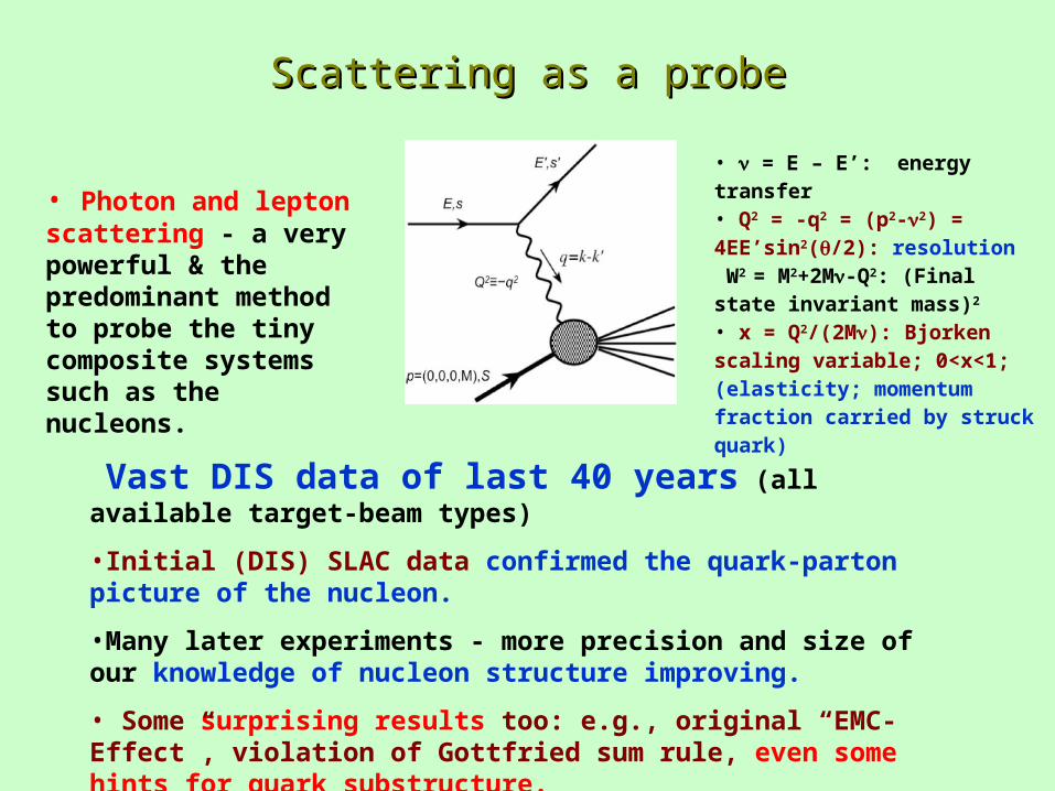
Scattering as a probeScattering as a probe
• = E – E’: energy transfer • Q2 = -q2 = (p2-2) = 4EE’sin2(/2): resolution W2 = M2+2M-Q2: (Final state invariant mass)2 • x = Q2/(2M): Bjorken scaling variable; 0<x<1; (elasticity; momentum fraction carried by struck quark)
• Photon and lepton scattering - a very powerful & the predominant method to probe the tiny composite systems such as the nucleons.
Vast DIS data of last 40 years (all available target-beam types)
•Initial (DIS) SLAC data confirmed the quark-parton picture of the nucleon.
•Many later experiments - more precision and size of our knowledge of nucleon structure improving.
• Some surprising results too: e.g., original “EMC-Effect”, violation of Gottfried sum rule, even some hints for quark substructure.
Nucleon Spin Thru the high Nucleon Spin Thru the high QQ22 microscope: microscope: Spin CrisisSpin Crisis
• Spin-averaged quark structure – studied and understood a lot .
• Spin-structure - not much known – polarization techniques not available before.
• Naïve Parton Model (NPM) predicts: Quarks give 60% of the nucleon spin
• Last 3 decades - great advances in polarization technology.
• Many subsequent experiments extracted g1 and g2 (functions of the quark-spin
distribution)
• First experiments at SLAC (limited kinematics) seemed to confirm the NPM predictions.
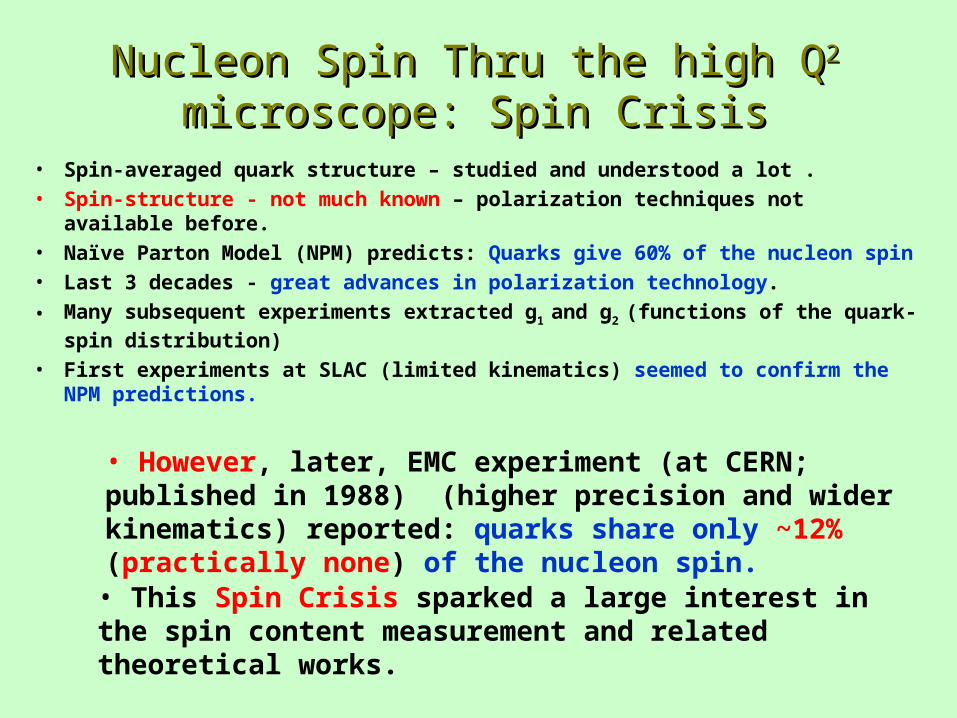
• However, later, EMC experiment (at CERN; published in 1988) (higher precision and wider kinematics) reported: quarks share only ~12% (practically none) of the nucleon spin.
• This Spin Crisis sparked a large interest in the spin content measurement and related theoretical works.
• Subsequent theoretical advances in QCD clarified spin-picture more
• Bjorken sum rule is a precise test of QCD.
• Interpretation of existing DIS results:
• verified the Bjorken sum rule with ~10% accuracy
• only ~3010% of the nucleon spin is due to quarks.
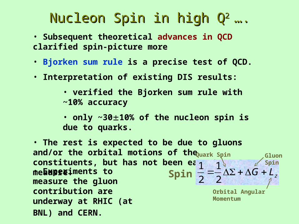
• The rest is expected to be due to gluons and/or the orbital motions of the constituents, but has not been easy to meausre.
Spin zLG 2
1
2
1Quark Spin Gluon
Spin
Orbital Angular Momentum
• Experiments to measure the gluon contribution are underway
at RHIC (at BNL) and CERN.
Nucleon Spin in high Nucleon Spin in high QQ2 2 ….….
• Low resolution – information on long distance structure, static properties.
• “spin crisis” led Anselmino et al. to examine the previously unappreciated GDH sum rule (formulated in 1960’s)
• The sum rule is connected to the DIS region as an analytic extension of Bjorken sum rule towards the real photon point.
• It implies a negative slope (w. r. t. Q2) of 1 at the photon point.
• Later, Burkert et al. - rapid transition of 1 between the real photon point
and the DIS region is saturated by contributions from nucleon resonances.
• Then Ji et al. extended the GDH sum rule beyond the real photon point.
• This theoretical progress triggered a large interest in testing those predictions
• A large experimental spin-program underway at Jlab (includes EG4) and elsewhere.
Probing at the other end of the energy scaleProbing at the other end of the energy scale
GDH Sum ruleGDH Sum rule
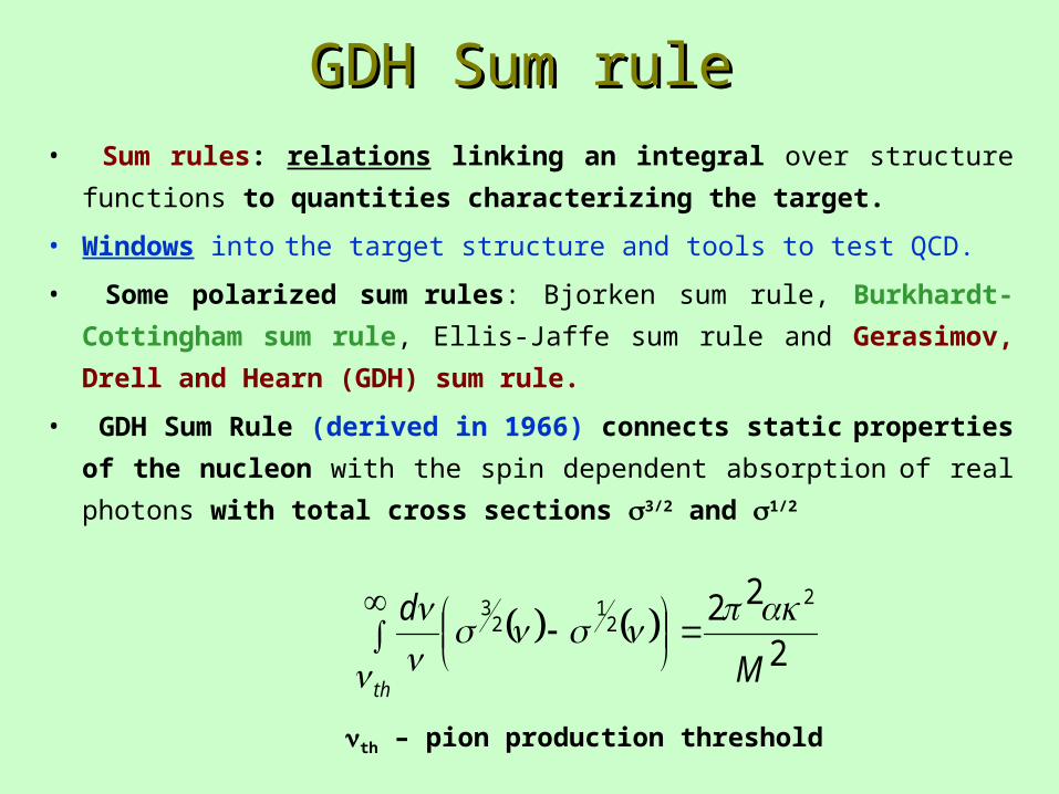
• Sum rules: relations linking an integral over structure functions to
quantities characterizing the target.
• Windows into the target structure and tools to test QCD.
• Some polarized sum rules: Bjorken sum rule, Burkhardt-Cottingham sum
rule, Ellis-Jaffe sum rule and Gerasimov, Drell and Hearn (GDH) sum
rule.
• GDH Sum Rule (derived in 1966) connects static properties of the
nucleon with the spin dependent absorption of real photons with total cross
sections 3/2 and 1/2
2
22 22
12
3
M
d
th
th – pion production threshold
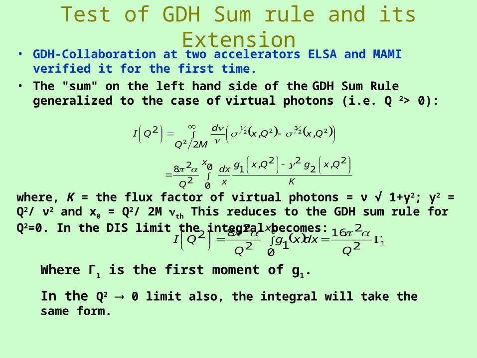
Test of GDH Sum rule and its Extension• GDH-Collaboration at two accelerators ELSA and MAMI verified it
for the first time.
• The "sum" on the left hand side of the GDH Sum Rule generalized to the case of virtual photons (i.e. Q 2> 0):
22
3221
2,,
2
2 QxQxMQ
dQI
0
0
2,2
22,1
2
28x
K
QxgQxg
x
dx
Q
where, K = the flux factor of virtual photons = ν √ 1+γ2; γ2 = Q2/ ν2 and x0 = Q2/ 2M th This reduces to the GDH sum rule for Q2=0. In the DIS limit the integral becomes:
1
0
2
216
012
282
Qdx
xxg
QQI
Where Γ1 is the first moment of g1.
In the Q2 0 limit also, the integral will take the same form.
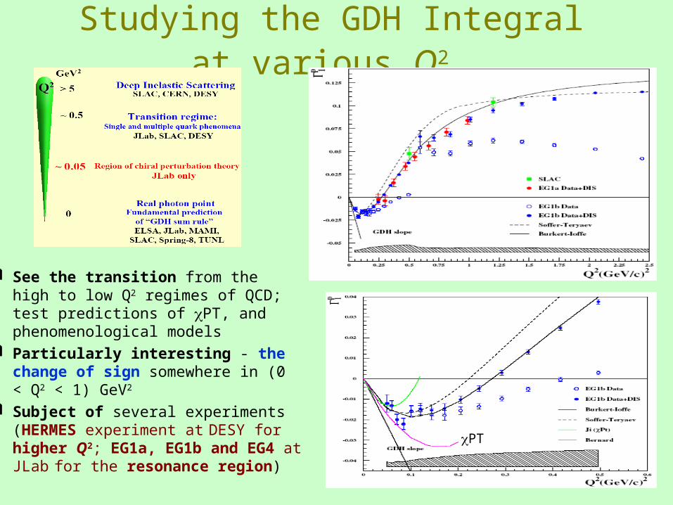
Studying the GDH Integral at various Q2
See the transition from the high to low Q2 regimes of QCD; test predictions of PT, and phenomenological models
Particularly interesting - the change of sign somewhere in (0 < Q2 < 1) GeV2
Subject of several experiments (HERMES experiment at DESY for higher Q2; EG1a, EG1b and EG4 at JLab for the resonance region)
PT
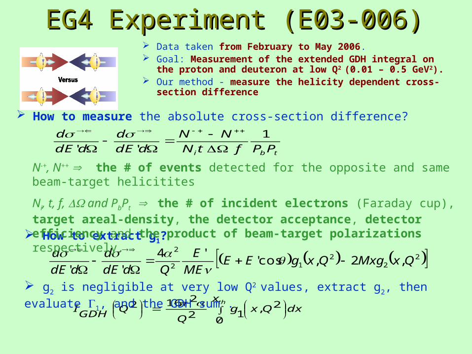
EG4 Experiment (E03-006)EG4 Experiment (E03-006) Data taken from February to May 2006. Goal: Measurement of the extended GDH integral on the proton
and deuteron at low Q2 (0.01 – 0.5 GeV2). Our method - measure the helicity dependent cross-section
difference
22
212
2
,2,cos''4
''QxMxgQxgEE
ME
E
QddE
d
ddE
d
How to extract g1?
dxx
QxgQ
QGDH
Ith
0
2,12
2162
tbi PPftN
NN
ddE
d
ddE
d 1
''
N-+, N++ the # of events detected for the opposite and same beam-target helicitites
Ni, t, f, and PbPt the # of incident electrons (Faraday cup), target areal-density, the detector acceptance, detector efficiency and the product of beam-target polarizations respectively.
How to measure the absolute cross-section difference?
g2 is negligible at very low Q2 values, extract g2, then evaluate 1, and the GDH sum .
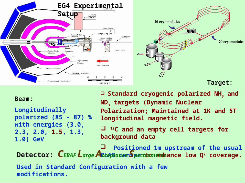
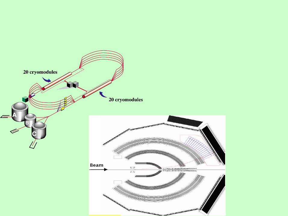
EG4 Experimental Setup
Beam:
Longitudinally polarized (85 – 87) % with energies (3.0, 2.3, 2.0, 1.5, 1.3, 1.0) GeV
Target:
Standard cryogenic polarized NH3 and ND3 targets
(Dynamic Nuclear Polarization; Maintained at 1K and 5T longitudinal magnetic field.
12C and an empty cell targets for background data
Positioned 1m upstream of the usual CLAS center to enhance low Q2 coverage.
Detector: CEBAF Large Acceptance Spectrometer
Used in Standard Configuration with a few modifications.
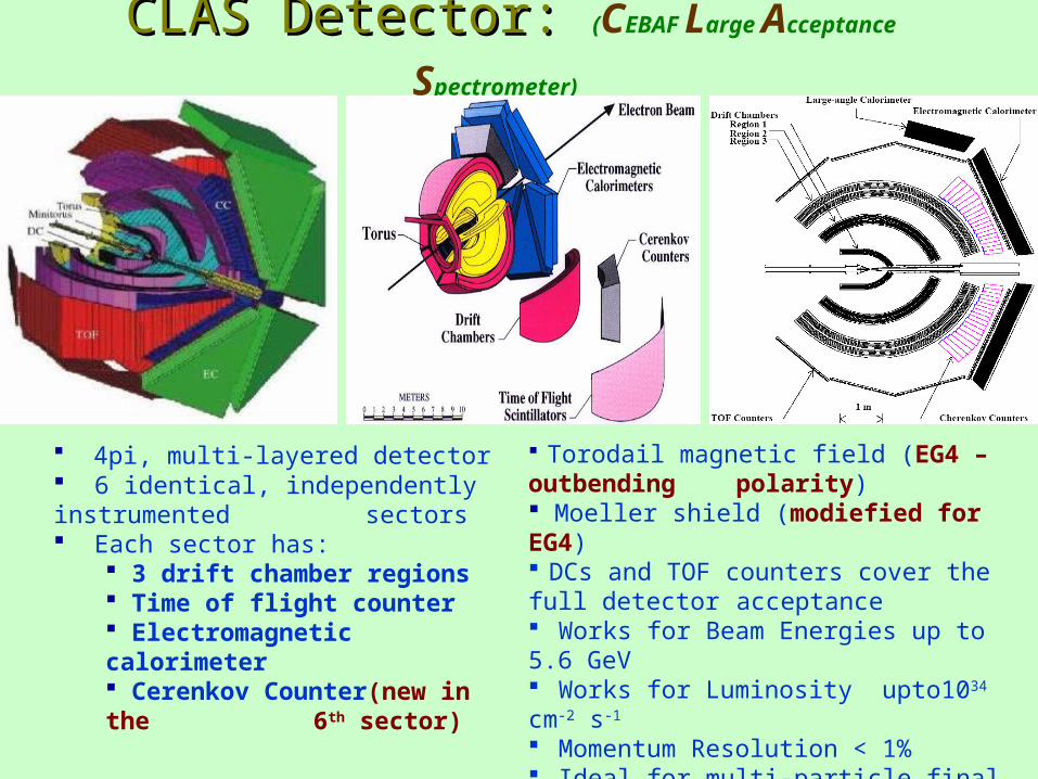
CLAS Detector: CLAS Detector: (CEBAF Large Acceptance Spectrometer)
4pi, multi-layered detector 6 identical, independently instrumented
sectors Each sector has:
3 drift chamber regions Time of flight counter Electromagnetic calorimeter Cerenkov Counter(new in the
6th sector)
Torodail magnetic field (EG4 – outbending polarity)
Moeller shield (modiefied for EG4) DCs and TOF counters cover the full detector
acceptance Works for Beam Energies up to 5.6 GeV Works for Luminosity upto1034 cm-2 s-1
Momentum Resolution < 1% Ideal for multi-particle final states
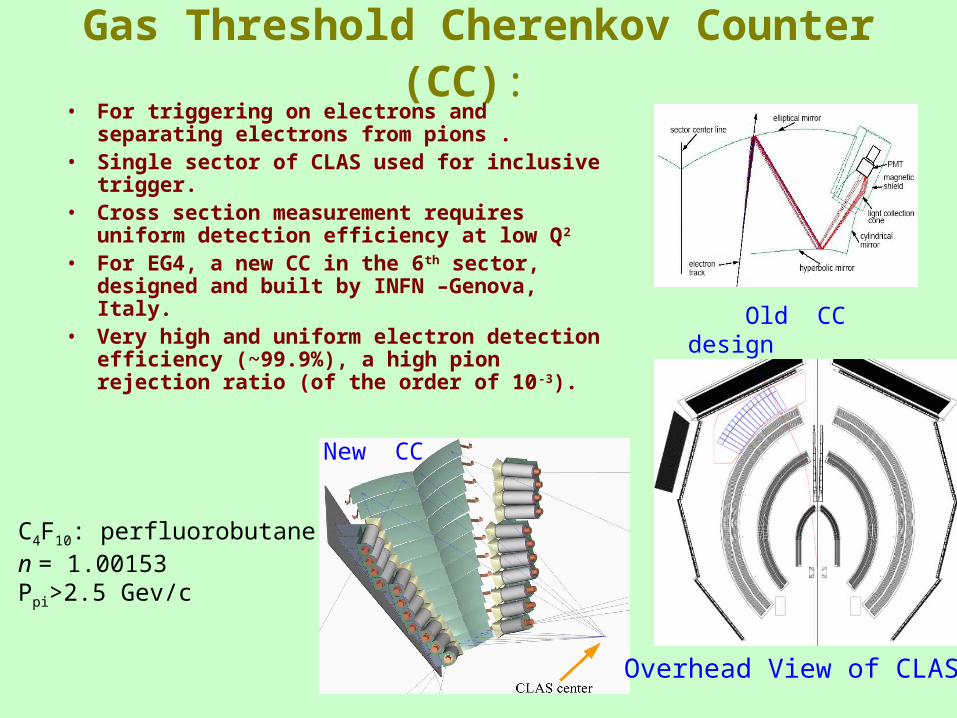
Gas Threshold Cherenkov Counter (CC): • For triggering on electrons and separating
electrons from pions .• Single sector of CLAS used for inclusive trigger.• Cross section measurement requires uniform
detection efficiency at low Q2
• For EG4, a new CC in the 6th sector, designed and built by INFN –Genova, Italy.
• Very high and uniform electron detection efficiency (~99.9%), a high pion rejection ratio (of the order of 10-3).
Overhead View of CLAS
C4F10: perfluorobutanen = 1.00153Ppi>2.5 Gev/c
New CC
Old CC design
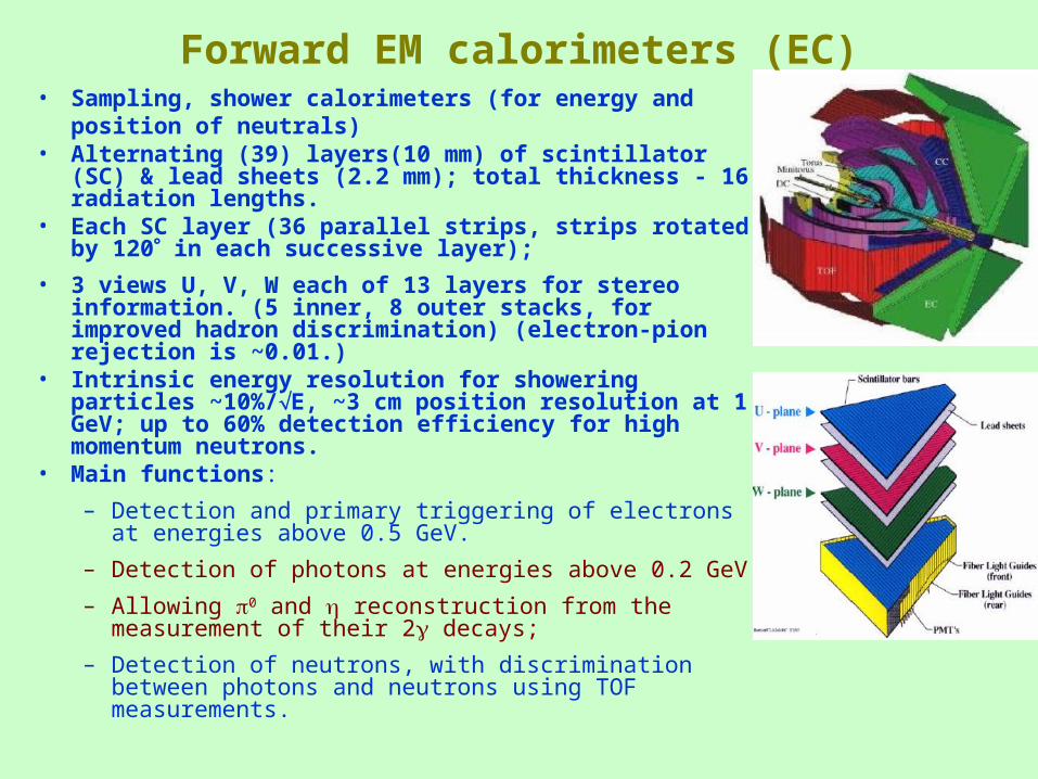
• Sampling, shower calorimeters (for energy and position of neutrals)
• Alternating (39) layers(10 mm) of scintillator (SC) & lead sheets (2.2 mm); total thickness - 16 radiation lengths.
• Each SC layer (36 parallel strips, strips rotated by 120 in each successive layer);
• 3 views U, V, W each of 13 layers for stereo information. (5 inner, 8 outer stacks, for improved hadron discrimination) (electron-pion rejection is ~0.01.)
• Intrinsic energy resolution for showering particles ~10%/E, ~3 cm position resolution at 1 GeV; up to 60% detection efficiency for high momentum neutrons.
• Main functions:
– Detection and primary triggering of electrons at energies above 0.5 GeV.
– Detection of photons at energies above 0.2 GeV.
– Allowing 0 and reconstruction from the measurement of their 2 decays;
– Detection of neutrons, with discrimination between photons and neutrons using TOF measurements.
Forward EM calorimeters (EC)
My Work: EC-timing CalibrationMy Work: EC-timing Calibration
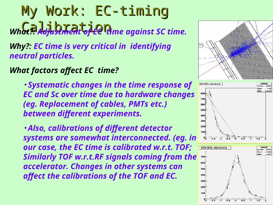
What?: Adjustment of EC time against SC time.
Why?: EC time is very critical in identifying neutral particles.
What factors affect EC time?
•Systematic changes in the time response of EC and Sc over time due to hardware changes (eg. Replacement of cables, PMTs etc.) between different experiments.
•Also, calibrations of different detector systems are somewhat interconnected. (eg. in our case, the EC time is calibrated w.r.t. TOF; Similarly TOF w.r.t.RF signals coming from the accelerator. Changes in other systems can affect the calibrations of the TOF and EC.
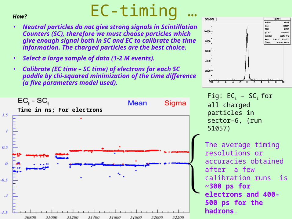
EC-timing …How?
• Neutral particles do not give strong signals in Scintillation Counters (SC), therefore we must choose particles which give enough signal both in SC and EC to calibrate the time information. The charged particles are the best choice.
• Select a large sample of data (1-2 M events).
• Calibrate (EC time – SC time) of electrons for each SC paddle by chi-squared minimization of the time difference (a five parameters model used).
The average timing resolutions or accuracies obtained after a few calibration runs is ~300 ps for electrons and 400-500 ps for the hadrons.
Time in ns; For electrons
Fig: ECt – SCt for all
charged particles in sector–6, (run 51057)
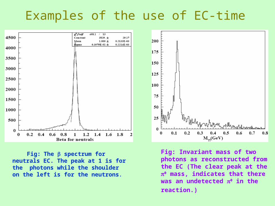
Examples of the use of EC-time
Fig: The spectrum for neutrals EC. The peak at 1 is for the photons while the shoulder on the left is for the neutrons.
Fig: Invariant mass of two photons as reconstructed from the EC (The clear peak at the 0 mass, indicates that there
was an undetected 0 in the reaction.)
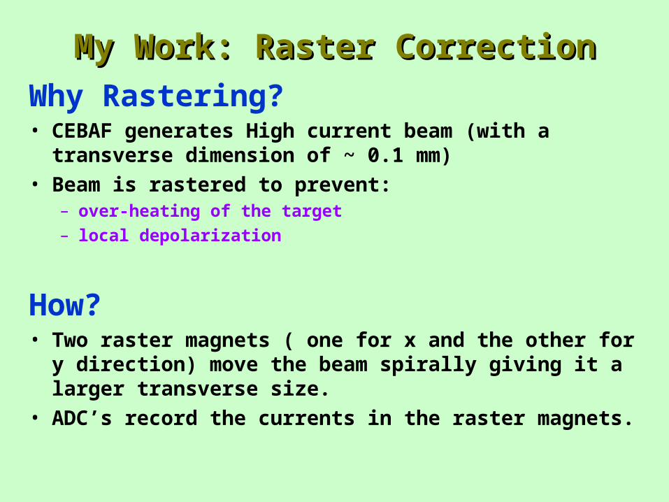
My Work: Raster CorrectionMy Work: Raster Correction
Why Rastering?• CEBAF generates High current beam (with a transverse
dimension of ~ 0.1 mm)
• Beam is rastered to prevent:– over-heating of the target
– local depolarization
How?• Two raster magnets ( one for x and the other for y direction)
move the beam spirally giving it a larger transverse size.
• ADC’s record the currents in the raster magnets.
Raster Correction
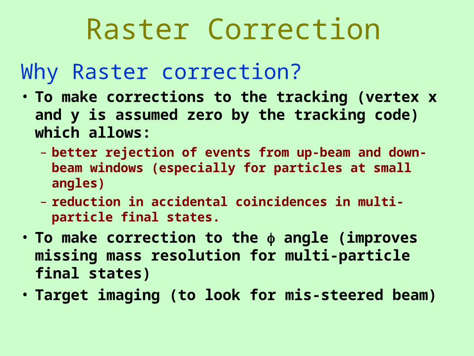
Why Raster correction?• To make corrections to the tracking (vertex x and y
is assumed zero by the tracking code) which allows:– better rejection of events from up-beam and down-beam
windows (especially for particles at small angles)
– reduction in accidental coincidences in multi-particle final states.
• To make correction to the angle (improves missing mass resolution for multi-particle final states)
• Target imaging (to look for mis-steered beam)
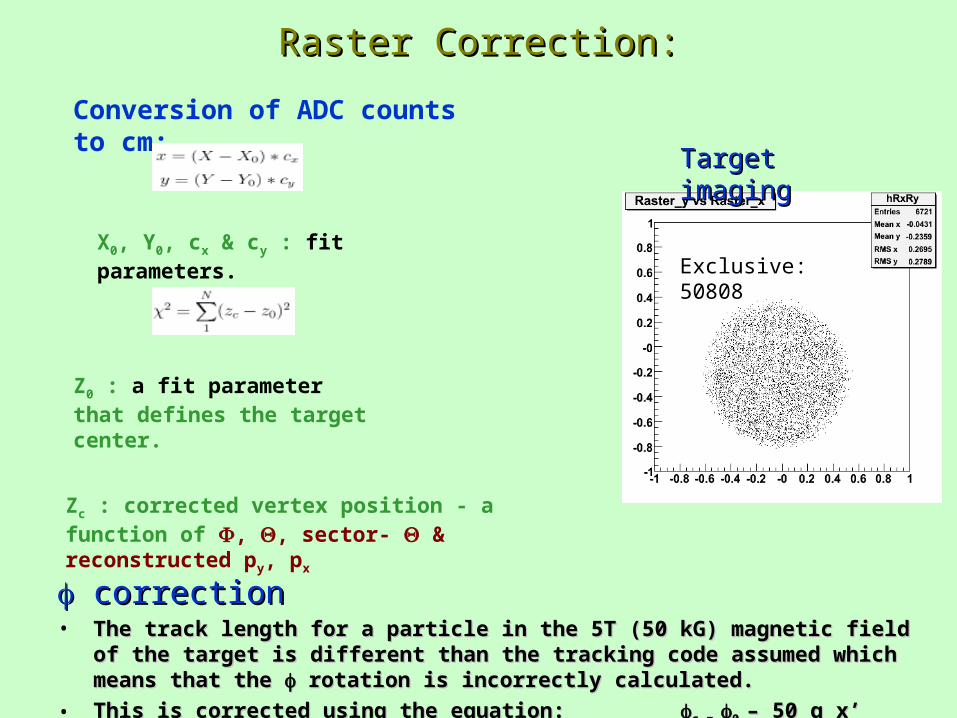
Raster Correction:Raster Correction:
Exclusive: 50808
Zc : corrected vertex position - a function of , , sector- & reconstructed py, px
Conversion of ADC counts to cm:
X0, Y0, cx & cy : fit parameters.
correctioncorrection• The track length for a particle in the 5T (50 kG) magnetic field of the target is different The track length for a particle in the 5T (50 kG) magnetic field of the target is different
than the tracking code assumed which means that the than the tracking code assumed which means that the rotation is incorrectly calculated. rotation is incorrectly calculated.
• This is corrected using the equation: This is corrected using the equation: c = c = 0 0 – 50 q x’ /(100* 33.356 *p– 50 q x’ /(100* 33.356 *ptt))
Target imagingTarget imaging
Z0 : a fit parameter that defines the target center.
Future Work
• Momentum Correction• Background subtraction• Final definition of all cuts• Beam and target polarization determination.• Acceptance and Efficiency of electron detection in CLAS
(From simulations and comparison with known cross sections.)
• Radiative corrections• Development of models• Extraction of g1, integration for its moment(s)• Neutron information extraction.
Summary• As part of an attempt to understand the spin structure of
nucleons, we plan to measure the spin structure function g1, its first moment 1 and the extended GDH integral at very low Q2 (0.01 – 0.5 GeV2) values using EG4 data on proton and deuteron.
• The data is already available, and I worked on EC time calibration and Raster correction. EC timing is complete, Raster work is underway.
• I will start working on Momentum correction very soon.
• My thesis will be on the neutron spin-structure (extract g1, 1 and the extended GDH integral for the neutron)
References(1) Wikipedia: Standard Model. (http://en.wikipedia.org/wiki/Standard_Model)
(2) S. E. Kuhn, Nucleon Structure Functions: Experiments and Models, HUGS ’97.
(3) S. E. Kuhn and G. E. Dodge, Private communications.
(4) K. J. Slifer, Ph. D. thesis, Temple University.
(5) R. Milner;HERMES physics, a historical perspective (A ppt presentation for HERA symposium June 30, 2007)
(6) M. Ripani, Private communication.
(7) K.G. Vipuli G. Dharmawardane, Ph.D. thesis, Old Dominion University
(8) K.J. Slifer and A. Deur Private communications.
(9) M.Battaglieri, et al. 2003 Jefferson Lab proposal E03-006
(10) http://galileo.phys.virginia.edu/classes/sajclub/gdh.html
(11) M. Amarian et al., The CLAS forward electromagnetic calorimeter, Nucl. Instr. And Meth. 460 (2000) 239 – 265.
(12) P. Bosted et al., Raster Corrections for EG1b, CLAS-NOTE-2003-008.
(13) http://www.krl.caltech.edu/~johna/thesis/node19.html
(14) R. De Vita, Private communications.
(15) A. Klimenko and S. Kuhn, Momentum corrections for E6, CLAS-NOTE-2003-005.
(16) K. Park et al., Kinematics Corrections for CLAS, CLAS-NOTE-2003-012.
(17) http://people.virginia.edu/~xz5y/Research.html
(18) M. Anghinolfi et al., The GDH Sum Rule with Nearly-Real Photons and the Proton g1 Structure Function at Low Momentum Transfer. Jlab PR
03-006.
(19) A. Deur, Experimental Studies of Spin Stucture in Light Nuclei, EINN07.
(20) J. Zhang, Measurement of Exclusive - Electro-production from the Neutron in the Resonance Region, Oral qualifying exam report, 2006.
(21) http://www-meg.phys.cmu.edu/~bellis/dc/dcintro.html
(22) http://ikpe1101.ikp.kfa-juelich.de/cosy-11/exp/drift_chambers/DriftChambers_E.html
(23) W. Brooks, CLAS – A Large Acceptance Spectrometer for Intermediate Energy Electromagnetic Nuclear Physics.
(24) B.A. Mecking, et al, The CEBAF large acceptance spectrometer (CLAS), Nucl. Instr. And Meth. A 503 (2003) 513 – 553.
(25) http://www.shef.ac.uk/physics/teaching/phy311/scintillator.html
(26) Matthieu Guillo et al., EC Time Calibration Procedure For Photon Runs in CLAS, CLAS-NOTE 2001-014, August 20, 2001.
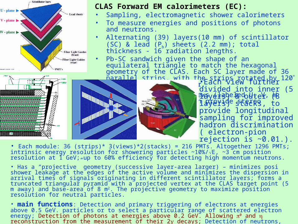
CLAS Forward EM calorimeters (EC):• Sampling, electromagnetic shower calorimeters• To measure energies and positions of photons and neutrons.• Alternating (39) layers(10 mm) of scintillator (SC) & lead (Pb) sheets
(2.2 mm); total thickness - 16 radiation lengths.• Pb-SC sandwich given the shape of an equilateral triangle to match the
hexagonal geometry of the CLAS. Each SC layer made of 36 parallel strips, with the strips rotated by 120 in each successive layer.
• Thus 3 orientations/ views (labeled U, V, W each of 13 layers) which provide stereo information.
•Each view further divided into inner (5 layers) & outer (8 layers) stacks, to provide longitudinal sampling for improved hadron discrimination ( electron-pion rejection is ~0.01.).
• Each module: 36 (strips)* 3(views)*2(stacks) = 216 PMTs. Altogether 1296 PMTs; intrinsic energy resolution for showering particles ~10%/E, ~3 cm position resolution at 1 GeV; up to 60% efficiency for detecting high momentum neutrons.
• Has a “projective” geometry (successive layer-area larger) – minimizes posi shower leakage at the edges of the active volume and minimizes the dispersion in arrival times of signals originating in different scintillator layers; forms a truncated triangular pyramid with a projected vertex at the CLAS target point (5 m away) and base-area of 8 m 2. The projective geometry to maximize position resolution for neutral particles.
• main functions: Detection and primary triggering of electrons at energies above 0.5 GeV. particles or to select a particular range of scattered electron energy; Detection of photons at energies above 0.2 GeV. Allowing 0 and reconstruction from the measurement of their 2 decays; Detection of neutrons, with discrimination between photons and neutrons using TOF measurements.
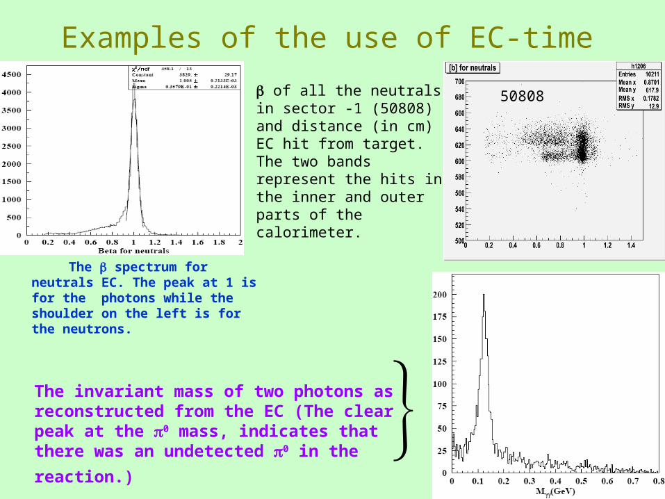
Examples of the use of EC-time
The spectrum for neutrals EC. The peak at 1 is for the photons while the shoulder on the left is for the neutrons.
The invariant mass of two photons as reconstructed from the EC (The clear peak at the 0 mass, indicates
that there was an undetected 0 in the reaction.)
of all the neutrals in sector -1 (50808) and distance (in cm) EC hit from target. The two bands represent the hits in the inner and outer parts of the calorimeter.
50808
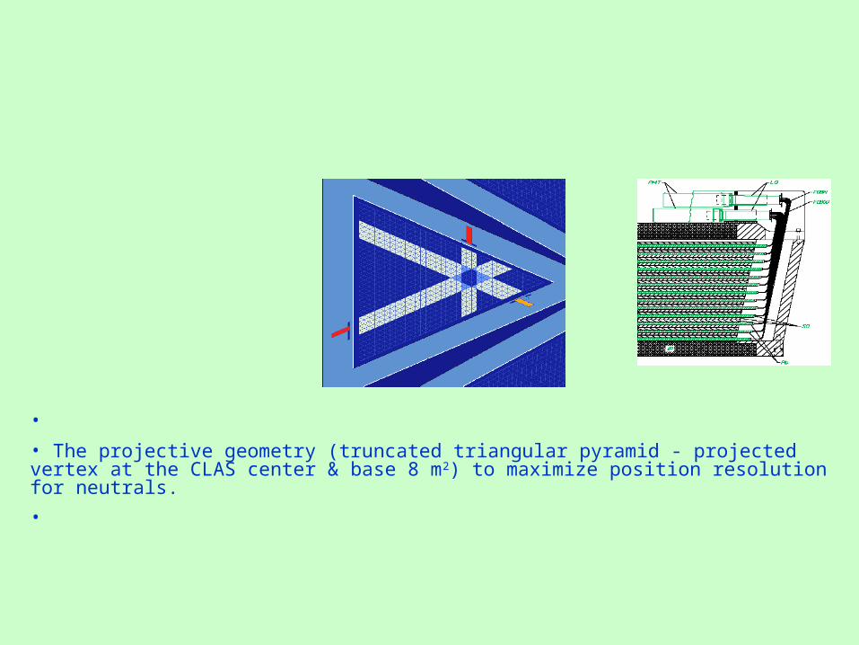
•
• The projective geometry (truncated triangular pyramid - projected vertex at the CLAS center & base 8 m2) to maximize position resolution for neutrals.
•
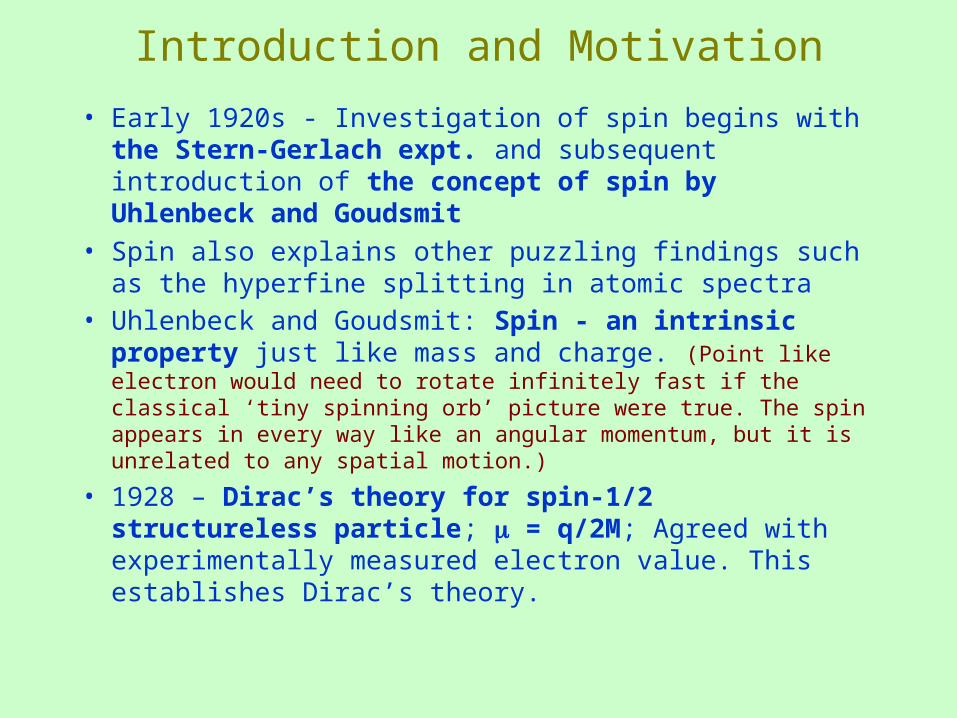
Introduction and Motivation
• Early 1920s - Investigation of spin begins with the Stern-Gerlach expt. and subsequent introduction of the concept of spin by Uhlenbeck and Goudsmit
• Spin also explains other puzzling findings such as the hyperfine splitting in atomic spectra
• Uhlenbeck and Goudsmit: Spin - an intrinsic property just like mass and charge. (Point like electron would need to rotate infinitely fast if the classical ‘tiny spinning orb’ picture were true. The spin appears in every way like an angular momentum, but it is unrelated to any spatial motion.)
• 1928 – Dirac’s theory for spin-1/2 structureless particle; = q/2M; Agreed with experimentally measured electron value. This establishes Dirac’s theory.
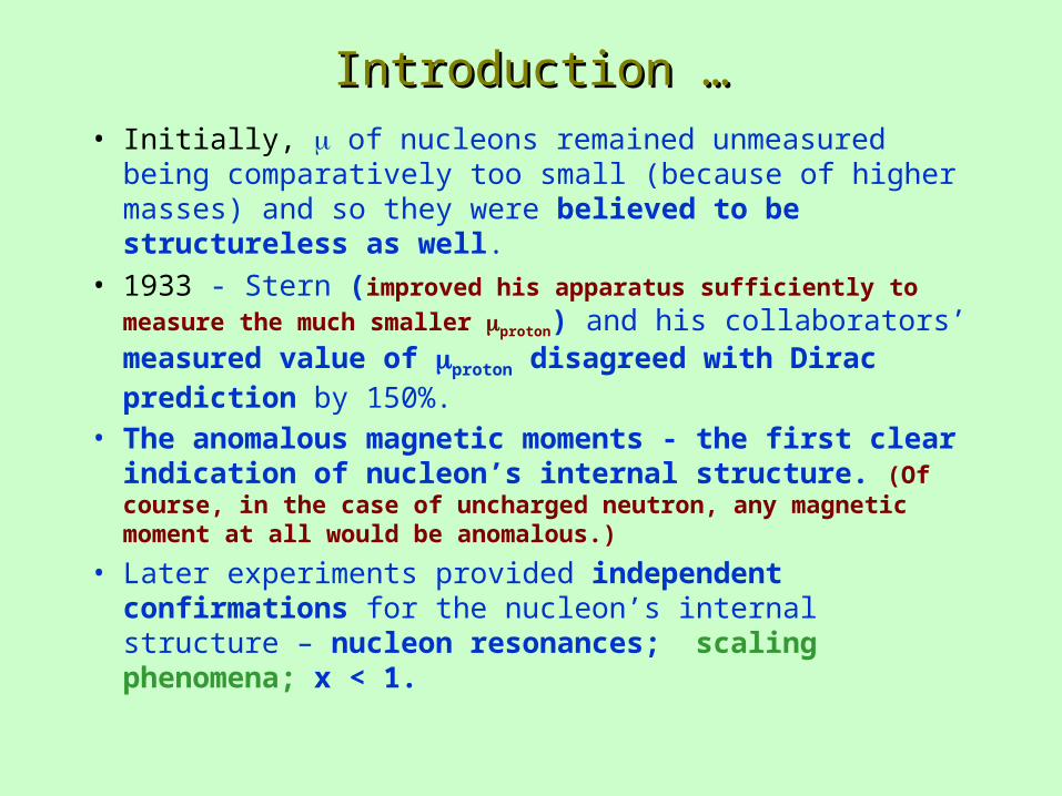
Introduction …Introduction …
• Initially, of nucleons remained unmeasured being comparatively too small (because of higher masses) and so they were believed to be structureless as well.
• 1933 - Stern (improved his apparatus sufficiently to measure the
much smaller proton) and his collaborators’ measured value of proton disagreed with Dirac prediction by 150%.
• The anomalous magnetic moments - the first clear indication of nucleon’s internal structure. (Of course, in the case of uncharged neutron, any magnetic moment at all would be anomalous.)
• Later experiments provided independent confirmations for the nucleon’s internal structure – nucleon resonances; scaling phenomena; x < 1.
BeamBeam• TJNAF –electron beam.
• Energy upto 5.7 GeV (injector - 45 MeV; 1500 MHz bunch structure)
• Hall B.