Embed Size (px)
Citation preview

Nucleus PagingStation
Installation and Operation
Issue Date: December 1997
6881002F05-O
Series: Wireless Messaging System
System Version: 1.06
®

Nucleus PagingStation
Installation and Operation
Issue Date: December 1997
6881002F05-O
Series: Wireless Messaging System
System Version: 1.06
®

Nucleus ® Paging Station Installation and Operation
01/2
2/97
Foreword
General InformationThe information in this manual has been reviewed for accuracy. However, no responsibility isassumed for inaccuracies. Motorola reserves the right to make changes to any products discussedherein. The information in this document is subject to change without notice. Motorola assumes noliability for hardware or software damage or loss of data because of errors or omissions in thismanual. Motorola does not assume any liability arising from the application or use of any products orcircuits described herein. Neither does Motorola convey any license under its patents or right ofothers.
Refer questions concerning the contents of this manual or requests for related circuit boardinformation to the following location:
Motorola, Inc.Paging Systems GroupMultimedia Publications Department5401 North Beach St., MS E230-AFort Worth, TX 76137-2794
or telephone: (817) 245-2823
To access on-line electronic information (BBS) for service notices and the latest software releases, callthe Paging One-Call-Support Center. To request additional manuals or parts, please contact theMotorola Americas Parts Division:
telephone: (800) 422-4210facsimile: (847) 538-8198
To request a part number, contact the Parts Identification Group:
telephone: (847) 538-0021
For Motorola Infrastructure and communicator test equipment, contact the Motorola Test EquipmentCenter:
telephone: (800) 505-8378
December 1997 6881002F05-O iii

Foreword Nucleus ® Paging Station Installation and Operation
Global Service Organization
Motorola provides Infrastructure and communicator technical support through authorized orcompany-owned Service Centers. Motorola also provides service for communicators on a contractbasis. For contract service information, please contact your local Motorola representative or the PagingOne-Call-Support Center:
Motorola, Inc.Paging One-Call-Support Center5401 North Beach St., MS E112Fort Worth, TX 76137-2794
telephone: (800) 520-7243 or(817) 245-4663
facsimile: (817) 245-2141
Service Training
Motorola, through its Advanced Messaging Technical Training Group in Fort Worth, Texas, offerscourses on communicators, messaging switches, transmitters, and receivers. These courses are taughton the site or at a customer’s location.
Students learn to install, configure, and maintain Motorola messaging systems. The classrooms atMotorola are equipped to ensure hands-on experience in practical lab exercises.
Training courses range from a basic introduction to communicators and messaging systems tocustomized classes on specific systems and large system applications.
To obtain a course catalog or scheduling information, please call (817) 245-2184 or (800) 724-3588 andask for the training coordinator.
Computer Software Copyrights
The Motorola products described in this manual might include copyrighted Motorola computersoftware stored in semiconductor memories and other media. Laws in the United States and othercountries preserve for Motorola certain exclusive rights for copyrighted computer programs,including the exclusive right to copy or reproduce in any form the copyrighted computer software.
Accordingly, any copyrighted Motorola computer software contained in the Motorola productsdescribed in this manual cannot be copied or reproduced in any manner without the express writtenpermission of Motorola.
Furthermore, the purchase of Motorola products does not grant, either directly or by implication,estoppel, or otherwise, any license under the copyrights, patents or patent applications of Motorola,except for the normal, nonexclusive, royalty-free license to use that arises by operation of law in thesale of a product.
iv 6881002F05-O December 1997
Nucleus ® Paging Station Installation and Operation Foreword
Trademarks
Motorola, the Motorola logo, and Nucleus, Reg. U.S. Pat. and TM. Off, Motorola, Inc.
FLEX, Paging One-Call-Support, RF-Baton!, and RF-B! are trademarks of Motorola, Inc.
Trademarks contained herein are the acknowledged property of their respective owners.
Important Safety Information
The installation, maintenance, and/or operation of this equipment may present potentially unsafeconditions, including, but not limited to, electrical shock, improper voltage to components, andimproper operation that can cause personal injury, death or damage to property.
Read Instructions: Read all the safety instructions before operating the equipment. Retain these safetyinstructions for future reference. Specialized procedures and instructions are required and must befollowed. Also, all applicable safety procedures, such as Occupational, Safety, and HealthAdministration (OSHA) requirements, National Electric Code Requirements, local code requirements,safe working practices, and good judgement must be used by personnel.
Heed Admonitions: Adhere to all warnings on the equipment and in the operating instructions.Follow all operating and use instructions. Two safety admonitions are used in this instruction manualto indicate:
• Equipment damage–
• Personal injury or injury that may result in death–
Mounting: Mount the equipment only as recommended by the manufacturer. Situate the equipmentaway from heat sources such as radiators, heat registers, stoves, or other equipment (includingamplifiers) that produces heat.
Power Sources and Grounding: Connect the equipment to the type of power source described in theinstallation instructions or as marked on the equipment. Take precautions to avoid defeating thegrounding or polarization provisions of the equipment. Disconnect the power to the equipment by acircuit breaker when left unused for long periods of time.
CAUTION
This safety admonition applies to an operating or maintenance procedure, practice orcondition which, if not strictly observed, could result in damage to the equipment ordatabase.
DANGER
This safety admonition applies to an operating or maintenanceprocedure, practice or condition which, if not strictly observed, couldresult in serious personal injury or death.
December 1997 6881002F05-O v

Foreword Nucleus ® Paging Station Installation and Operation
Cleaning: Clean the outside of the equipment by using only a damp cloth. Do not immerse theequipment in any type of liquid, including water. Do not use liquid cleaners or aerosol cleaners. Dirtor other foreign matter should not be allowed to accumulate in the interior of the enclosure.
Damage Requiring Service: Do not attempt to perform service functions that are not described in theoperating instructions. All other servicing should be referred to qualified service personnel.
Telephone Line Installation: All telephone line connections to the equipment should be accomplishedwith the telephone lines disconnected from the network interface.
Motorola is not responsible for static damage to equipment not sold under the Motorola logo.
Motorola, Inc. 1997. All rights reserved. Printed in the U.S.A.
vi 6881002F05-O December 1997

08/0
1/97
PSG Limited Equipment Warranty forNon-U.S. and Non-Canadian Markets
General Terms1. Motorola Paging Systems Group (PSG) manufactured infrastructure equipment is
warranted to be free from defects in material and workmanship to the original purchaseronly as set forth herein.
2. This Warranty covers only that equipment identified in paragraph 1 that is used in themanner and for the purpose intended.
3. This Warranty specifically excludes any and all software products from any source. PSGsoftware products are the subject of the PSG Software Maintenance Program, addressedseparately.
4. This Warranty shall commence 30 days after the date of shipment of the PSGinfrastructure equipment.
5. The term of Warranty for all PSG infrastructure equipment is one (1) year parts andlabor.
Limitations And Qualifications of Warranty
6. LIMITATION—THE REMEDY UNDER THIS WARRANTY IS LIMITED TOMOTOROLA'S REPAIR OR REPLACEMENT OF DEFECTIVE EQUIPMENT. THISWARRANTY IS IN LIEU OF ALL OTHER WARRANTIES OR CONDITIONS,EXPRESSED OR IMPLIED, INCLUDING, BUT NOT LIMITED TO, THE IMPLIEDWARRANTIES OF MERCHANTABILITY AND FITNESS FOR A PARTICULARPURPOSE.
7. This Warranty does not cover, nor include a remedy for, damages, defects or failurecaused by:
a. The equipment or any part of it NOT having been installed, modified, adapted,repaired, maintained, transported or relocated in accordance with Motorolatechnical specifications and instructions;
Revised July 1997 vii

Warranty
b. Storage not conforming to the Shipping, Receiving, and Installation section of theapplicable Motorola Equipment Manual;
c. Environmental characteristics not conforming to the applicable MotorolaEquipment Manual;
d. Nonconformance with the Equipment Operating Instructions in the applicableMotorola Equipment Manual;
e. External causes including, without limitation, use in conjunction with incompatibleequipment, unless such use was with or under Motorola's prior written consent;
f. Cosmetic damages;
g. Damages caused by external electrical stress;
h. Lightning;
i. Accidental damage;
j. Negligence, neglect, mishandling, abuse, or misuse;
k. Force Majeure; and
l. Damage caused by Shipper(s).
Return of Equipment
8. If an item of PSG infrastructure equipment malfunctions or fails in normal use within theWarranty Period:
a. The Customer shall promptly notify the nearest Motorola Area Customer CareCenter (CCC) of the problem and provide the serial number of the defective item.Motorola shall then, at its option, either resolve the problem over the telephone orissue a Return Authorization Number to the Customer. The Customer shall, at itscost, ship the item to the Motorola Area CCC location designated at the time theReturn Authorization Number is issued;
b. The Return Authorization Number must be shown on the label attached to eachreturned item. A description of the fault must accompany each returned item. Thereturned item must be properly packed, and the insurance and shipping chargesprepaid;
c. Motorola shall either repair or replace the returned item. The replacement item maybe new or refurbished. When refurbished, it shall be equivalent to new in operation.When a returned item is replaced by Motorola, the returned item shall become theproperty of Motorola;
viii Revised February 1997

Warranty
d. Subject to all the terms of this Warranty, part availability and the clearance ofCustoms, Motorola shall complete the repair or exchange of Motorola-manufacturedequipment returned under Warranty within fifteen (15) working days of receipt ofthe equipment;
e. Motorola shall, at its cost, ship the repaired or replaced item to the Customer. If theCustomer has requested Express Shipping, the Customer shall pay Motorola anexpedite fee; and
f. Equipment which is repaired or replaced by Motorola shall be free of defects inmaterial and workmanship for the remainder of the original Warranty, or for 90 daysfrom the date of repair or replacement, whichever is longer. All other terms of thisWarranty shall apply to such repairs or replacements.
Advance Replacements
9. During the Warranty Period:
a. At the Customer's request and for the Customer's convenience, Motorola maysupply the Customer with Advance Replacement Parts (parts furnished in advanceof Motorola's receipt of defective items). Motorola's provision of such parts will becontingent on part availability and on the Customer's maintaining a satisfactorycredit standing with Motorola.
b. Motorola shall ship the Advance Replacement Parts requested by the Customerwithin 48 hours of Motorola determining that such service is appropriate, if stock isavailable at the Motorola service location. If stock is not available, Motorola willmake reasonable efforts to locate and provide it to the Customer within ten (10)working days.
c. The Customer shall return defective items to the Motorola Area Customer CareCenter within thirty (30) days from the date of shipment of the AdvanceReplacement Parts; failing which, Motorola shall bill and the Customer shall pay thefull current list price of the Advance Replacement Parts.
10. To secure payment of the list price of Advance Replacement Parts if the defective itemsare not returned to Motorola, the Customer hereby grants to Motorola a purchase moneysecurity interest in any Advance Replacement Parts.
Revised February 1997 ix

Warranty
Excluded Equipment
11. The following equipment is excluded from this Warranty and is covered instead by theOriginal Equipment Manufacturer's Warranty:
a. Equipment which is not an integral part of a basic system configuration and whichis not manufactured by Motorola, such as batteries and satellite dish LNBs;
b. Peripheral equipment such as printers, modems, data loggers, video displayterminals, and lightning and surge protectors; and
c. Equipment which is not listed in Motorola's Price Book.
Force Majeure
12. Motorola shall not be responsible for failure to discharge its obligations under thisWarranty due to delays by suppliers, material shortages; strikes, lockouts or other labordisputes; disturbances, government regulations, floods, lightning, fires, wars, accidents,acts of God, and any other causes beyond Motorola's reasonable control.
Default and Termination
13. Motorola shall have the right to immediately terminate this Warranty, and to suspend itsperformance under this Warranty, upon notification to the Customer if the Customer:
a. Assigns or transfers the Customer's rights or obligations under this Warrantywithout the prior written consent of Motorola; or
b. Within thirty (30) days of written demand by Motorola, fails to pay (1) any chargefor Advance Replacement Parts supplied under this Warranty, if the Customer hasnot timely returned the defective items, or (2) any other amount that may be due.
14. Notwithstanding any such termination of the Warranty to the Customer, the Customershall remain responsible for all amounts then due.
Limitation of Liability
15. IN NO EVENT SHALL MOTOROLA BE LIABLE FOR ANY INDIRECT, INCIDENTAL,SPECIAL OR CONSEQUENTIAL DAMAGES ARISING OUT OF THIS WARRANTY,EVEN IF MOTOROLA HAS BEEN ADVISED OF THE POSSIBILITY THEREOF,INCLUDING, WITHOUT LIMITATION, LOST PROFITS AND REVENUES, FAILURETO REALIZE EXPECTED SAVINGS, LOST DATA OR ANY CLAIMS AGAINST THECUSTOMER BY A THIRD PARTY.
x Revised February 1997

Nucleus ® Paging Station Installation and Operation
Contents A
Introduction, 1-1
About this Manual, 1-2
Software Versions Supported, 1-4
Related Publications, 1-7
Specifications, 1-8
Options and Field Replaceable Units (FRUs), 1-13
FCC Type Acceptance Data, 1-16
Nucleus Paging Station Description, 2-1
General Description, 2-2
SCM, 2-3
Exciter, 2-6
Power Amplifier, 2-7
Power Supply, 2-10
Receiver Module, 2-11
Reference Modules, 2-13
Transmitter Controllers, 2-15
Installation Overview, 3-1
Purpose, 3-2
Grounding, Protection, and Shielding, 3-4
Environmental Conditions at the Site, 3-6
Input Power Requirements, 3-7
Equipment Mounting Methods, 3-8
Physical Dimensions and Clearances, 3-9
Recommended Tools and Equipment, 3-18
GPS Antenna Installation, 3-19
Mechanical Installation, 4-1
Equipment Unpacking and Inspection, 4-2
Installing 25-in., 46-in., and 70-in. Cabinets, 4-6
Mounting Procedures, 4-8
Connectors and Interfaces, 5-1
Backplane Interfaces, 5-2
Installing Communication Peripherals, 5-5
Installing Synchronization Peripherals, 5-10
December 1997 6881002F05-O xi
Contents Nucleus ® Paging Station Installation and Operation
Installing RF Interfaces and Antenna Options, 5-11
Installing Power, 5-14
Connecting the RF-B! Transmitter Controller, 5-24
NAC Wireline Configuration, 5-25
Front Panel Indicators and Controls, 6-1
Control Module Front Panel, 6-2
LEDs on Other Modules, 6-9
Basic Keypad Procedures, 7-1
Conventions, 7-2
Accessing the LED Display, 7-3
Changing the Password, 7-4
Disabling or Enabling the Password, 7-5
Changing Parameters from the Keypad, 7-6
The Menus, 7-8
SCM Station Configuration, 8-1
First Time Installation, 8-2
Station (STN) Configuration, 8-3
Transmit (TX) Configuration, 8-7
Options (OPT1) Configuration, 8-21
Alarm Setup (ASET) Configuration, 8-24
Configuration (CNFG), 8-30
SCM Station Alarms, Status, Troubleshooting, and Alignment, 9-1
Station Status, 9-2
Controlling Access to the Nucleus Paging Station, 9-4
Alarms, 9-8
Troubleshooting, 9-16
Alignment, 9-24
Advanced Power Measurements, 9-36
NAC Configuration, 10-1
Station Configuration, 10-2
Control Schemes, 10-6
Receivers, 10-17
Battery Revert Setup, 10-25
Other Configuration Parameters, 10-27
xii 6881002F05-O December 1997
Nucleus ® Paging Station Installation and Operation Contents
NAC Alignment and Equalization, 11-1
Station Alignment, 11-2
Frequency and Power Configuration, 11-8
Simulcast Equalization, 11-25
NAC Alarm Configuration and Verification, 12-1
Alarm Definitions, 12-2
Alarm Polling, 12-6
Unsolicited Alarm Reporting (UAR), 12-9
ASCII Diagnostics, 12-13
Wildcard Inputs/Outputs, 12-21
Alarm Verification Relay, 12-23
Modem Connections for Alarm Reporting, 12-27
Local Connection Without Modems, 12-32
Resetting Alarms, 12-33
Alarm Configuration for Alarms Based on Thresholds, 12-34
Alarms for N+1 Redundancy, 12-35
Replacing Modules, 13-1
General Replacement Information, 13-2
Replacing the Power Amplifier (PA) in a Standard Power Station, 13-5
Replacing the Power Amplifier (PA) in a Standard Power Station, 13-8
Replacing the Power Supply, 13-10
Replacing the Station Control Board and Exciter as a Matched Pair, 13-12
Backplane, 13-15
Acronyms, A-1
Configuration Record, B-1
Use in Initial Configuration, B-2
Use in Module Replacement, B-3
Internal Network Interface Unit (NIU), C-1
Internal NIU Function, C-2
Indicators, C-4
Interfaces, C-6
RF-Baton! Transmitter Controller Interface, D-1
Overview, D-2
WIB Interface, D-3
Replacement Procedure, D-5
December 1997 6881002F05-O xiii
Contents Nucleus ® Paging Station Installation and Operation
Receivers, E-1
Operation, E-3
Receiver Replacement Procedures, E-6
Testing and Tuning, E-19
GPS Antenna, F-1
Installation, F-2
Repairing an Installed Antenna, F-5
Replacing a GPS Receiver Module, F-9
xiv 6881002F05-O December 1997

Nucleus ® Paging Station Installation and Operation
Figures A
Figure 2-1: Station Control Board Block Diagram, 2-4Figure 2-2: Station Control Board Relationship with Receiver, 2-5Figure 2-3: Exciter Block Diagram, 2-6Figure 2-4: PA Block Diagram for a Standard Power Nucleus Paging Station, 2-8Figure 2-5: PA Block Diagram for a High Power Nucleus Paging Station, 2-9Figure 2-6: Power Supply Module, 2-10Figure 2-7: Receiver Module and CRIB Block Diagram, 2-11Figure 2-8: Reference Module with GPS Receiver, 2-13Figure 2-9: Reference Module with a UHSO or HSO, 2-14Figure 2-10: Wildcard Interface Board, 2-15Figure 2-11: Inputs and Outputs to an Internal NIU, 2-16Figure 3-1: Location of Electrostatic Ground Jacks, 3-5Figure 3-2: Side View of the Standard Power and High Power Stations Without a Cabinet, 3-10Figure 3-3: Top View of the Station Without a Cabinet, 3-11Figure 3-4: Clearance View of the Station Without a Cabinet, 3-11Figure 3-5: Front View of the 25-in. Station Cabinet, 3-12Figure 3-6: Side View of the 25-in. Station Cabinet, 3-12Figure 3-7: Drilling Template for a 25-in. Station Cabinet, 3-13Figure 3-8: Front View of the 46-in. Station Cabinet, 3-14Figure 3-9: Side View of the 46-in. Station Cabinet, 3-15Figure 3-10: Drilling Template for a 46-in. Station Cabinet, 3-15Figure 3-11: Front View of the 70-in. Station Cabinet, 3-16Figure 3-12: Side View of the 70-in. Station Cabinet, 3-17Figure 3-13: Drilling Template for a 70-in. Station Cabinet, 3-17Figure 3-14: GPS Antenna Mounting, 3-20Figure 4-1: Unpacking the Station Shipped Without a Cabinet, 4-2Figure 4-2: Removing the Cardboard Cover, 4-3Figure 4-3: Removing the Antistatic Bag, 4-4Figure 4-4: Removing the Bolts and Nuts, 4-4Figure 4-5: Attaching the Brackets to the Rails, 4-9Figure 4-6: Attaching Screws to the Brackets&, 4-10Figure 4-7: Resting the Standard Power Station on the Two Screws, 4-11Figure 4-8: Attaching the Screws to the Standard Power Cabinet, 4-12Figure 4-9: Pulling the PA from the Chassis, 4-14Figure 4-10: Attaching the Brackets to the Rails for a High Power Station, 4-15Figure 4-11: Attaching Screws to the Brackets for a High Power Station, 4-16Figure 4-12: Resting the Cage on the Two Screws, 4-17Figure 4-13: Attaching the Screws to the Cabinet, 4-18Figure 5-1: Backplane Connectors for a High Power Station (with Circulator Option), 5-2Figure 5-2: Backplane Connectors for a Standard Power Station, 5-3Figure 5-3: Backplane Connections for an Antenna Relay Module, 5-12Figure 5-4: Backplane Connections for Separate Transmit and Receive Antennas, 5-13
December 1997 6881002F05-O xv
Figures Nucleus ® Paging Station Installation and Operation
Figure 5-5: Ground Lug to Site Ground, 5-15Figure 5-6: Connector J31 Output to an RF-B! Transmitter Controller, 5-16Figure 5-7: AC Power (US 120 Vac Shown), 5-17Figure 5-8: DC Power Supply Option, 5-18Figure 5-9: Negative Voltage DC Power Supply, 5-19Figure 5-10: Positive Voltage DC Power Supply, 5-20Figure 5-11: Battery Revert in a High Power Station, 5-21Figure 5-12: Battery Revert for a Standard Power Nucleus Paging Station, 5-22Figure 5-13: Battery Temperature Sensor, 5-23Figure 5-14: Nucleus Paging Station to the RF-B! Transmitter Controller, 5-24Figure 6-1: Nucleus CM Front Panel, 6-2Figure 6-2: Nucleus with NAC Front Panel, 6-3Figure 6-3: SCM and NAC Front Panel Keypad, 6-4Figure 6-4: Exciter LEDs, 6-9Figure 6-5: Power Supply LEDs (Low Power Station Shown), 6-11Figure 7-1: Nucleus Paging Station Menu Logic, 7-7Figure 8-1: Carrier Deviations for 2-level and 4-level Normal and Inverted Transmissions, 8-16Figure 9-1: Test Equipment Setup, 9-18Figure 9-2: Correct Silent Carrier Wave Form, 9-20Figure 9-3: Modulation Wave Form, 9-20Figure 10-1: Local Control Scheme, 10-11Figure 11-1: Test Equipment Setup for Station Alignment Procedure, 11-3Figure 11-2: Test Equipment Setup for Power Output Alignment Procedure, 11-9Figure 11-3: Test Equipment Setup for Reference and Pendulum Alignment, 11-15Figure 11-4: Sample SRM Alignment Waveforms, 11-20Figure 11-5: Sample SRM Gain Waveforms, 11-20Figure 11-6: Closed Loop Audio Delay Measurement, 11-26Figure 12-1: Initial, Successful Login Screen, 12-18Figure 12-2: Initial, Unsuccessful Login Screen, 12-19Figure 12-3: Enter Password Screen, 12-19Figure 12-4: Main Menu, 12-20Figure 12-5: Alarm Verification Relay, 12-23Figure 13-1: Location of Ground Jack for Wrist Strap Connection, 13-2Figure 13-2: Location of N-type Connector and Mini-UHF Connector in a Standard Power
Nucleus Paging Station, 13-6Figure 13-3: Location of RF Output Connector in a High Power Nucleus Paging Station, 13-9Figure C-1: Internal NIU Interface to a Nucleus Paging Station, C-2Figure C-2: NIU Interfaces, C-3Figure C-3: SCM Front Panel Showing Internal NIU LEDs and Console Port, C-4Figure C-4: Model 259B Single-line RJ-45 Adapter, C-9Figure C-5: Model 258B Six-line RJ-45 Adapter, C-10Figure D-1: Pullup Resistor in a WIB Output, D-4Figure E-1: Link Receiver Application, E-3Figure E-2: Monitor Receiver Application, E-4Figure E-3: Location of the Ground Jack for the Wrist Strap Connection, E-6Figure E-4: Routing for the Receive Cable, E-9
xvi 6881002F05-O December 1997
Nucleus ® Paging Station Installation and Operation Figures
Figure E-5: Preselector Assembly in a VHF, 280 MHz, or UHF Module, E-10Figure E-6: Location of the Standoffs on the CRIB for an SCB, E-12Figure E-7: CRIB Mounted on the SCB, E-13Figure E-8: Location of the Standoffs for a NAC CRIB, E-14Figure E-9: CRIB Mounted on the NAC Board, E-15Figure E-10: Test Equipment Setup (UHF Has Three Screws), E-20Figure E-11: Location of Tuning Screws and Cavity Probe Holes, E-22Figure F-1: Assembled Antenna, Cable, and Bracket, F-3Figure F-2: Location and Orientation of the Cable and Connectors, F-6Figure F-3: Location and Orientation of the Cable Channel, Tab, and Slot, F-7Figure F-4: Mini-UHF Cable in the GPS Receiver Module, F-9
December 1997 6881002F05-O xvii

Figures Nucleus ® Paging Station Installation and Operation
xviii 6881002F05-O December 1997

Nucleus ® Paging Station Installation and Operation
Tables A
Table 1-1: Nucleus Software Compatibility Matrix, 1-5Table 1-2: NAC Software Compatibility Matrix, 1-6Table 1-3: Unit Sizes, 1-8Table 1-4: Cabinet Capacity, 1-9Table 1-5: Power Consumption, 1-9Table 1-6: Transmitter Performance Specifications, 1-10Table 1-7: Internal Link and Monitor Receiver Specifications, 1-11Table 1-8: Option Numbers and Descriptions, 1-13Table 1-9: FRU Numbers, 1-14Table 1-10: FCC Type Acceptance, 1-16Table 2-1: Frequencies for PAs with Exciter and Transmit Frequencies, 2-7Table 3-1: Required Environmental Conditions at the Site, 3-6Table 4-1: Stacking Limits for 25-in. and 46-in. Cabinets, 4-19Table 5-1: Backplane Connectors, 5-3Table 5-2: J14 PSTN Modem Channel Connector Pins and Signals, 5-5Table 5-3: J15 Paging Distribution Channel Connector Pins and Signals, 5-6Table 5-4: J17 50-pin Multipurpose Connector Pins and Signals, 5-7Table 5-5: J61 Wireline Connector Pins and Signals, 5-8Table 5-6: J19 Link Receiver Connector Pins and Signals, 5-10Table 5-7: J23 Antenna Relay Connector Pins and Signals, 5-11Table 5-8: J31 DC Power Connector Pins and Signals, 5-14Table 5-9: J24 Battery Temperature Connector Pins and Signals, 5-14Table 5-10: Nucleus DC Power Options, 5-17Table 5-11: Wireline Configuration for NAC Boards, 5-25Table 6-1: SCM Control Panel Keypad Functions, 6-5Table 6-2: SCM Control Panel LED Functions and Definitions, 6-7Table 6-3: NAC Control Panel LED Functions and Definitions, 6-7Table 6-4: Exciter LED Functions and Definitions, 6-9Table 6-5: Power Supply LED Functions and Definitions (All Power Supplies), 6-11Table 7-1: Notational Conventions for Presenting Software Procedures, 7-2Table 7-2: Hierarchical SCM Menu Structure, 7-8Table 7-3: Hierarchical NAC Menu Structure, 7-17Table 8-1: Carrier Offset, 8-11Table 8-2: Recommended Splatter Filters, 8-14Table 8-3: Carrier Deviations for Normal and Inverted Data, 8-16Table 8-4: Idle Deviation Frequency, 8-19Table 9-1: Status Values, 9-3Table 9-2: Alarms and Their Interpretations, 9-8Table 9-3: Mathematical Operations with dB and dBm, 9-38Table 10-1: Frequency Ranges, 10-3Table 11-1: Mixed Analog Simulcast Setup, 11-30Table 11-2: HSO and UHSO Frequency Adjustments, 11-31Table 12-1: Option Alarms, 12-2Table 12-2: Station Alarms, 12-2Table 12-3: MDC Communication Alarms, 12-3Table 12-4: RS-232 Communication Alarms, 12-4Table 12-5: LAN Communication Alarms, 12-4Table 12-6: Miscellaneous Alarms, 12-5Table 12-7: Switchover Alarms, 12-5
December 1997 6881002F05-O xix
Tables
Table 12-8: ASCII Diagnostics Function Keys Related to NAC Front Panel Keys, 12-18Table 12-9: UDS 2440 Modem Configuration, 12-28Table 12-10: Practical Peripherals PM1200SA Mini Configuration, 12-29Table 12-11: US Robotics Sportster 2400, 12-29Table 12-12: Station to External Modem Pin Assignments, 12-30Table 12-13: Station to External Terminal Pin Assignments, 12-30Table 12-14: Alarms Based on Thresholds, 12-34Table A-1: List of Acronyms, A-1Table B-1: Nucleus SCM Hierarchical Menu Structure, B-3Table B-2: Hierarchical NAC Menu Structure, B-8Table C-1: LED Functions and Definitions for the Internal NIU, C-4Table C-2: J19 Link Receiver Pinouts, C-7Table C-3: J15 Paging Distribution Channel Pinouts, C-8Table C-4: Model 259B Modular Spring Positions, C-9Table C-5: Model 258B Modular Spring Positions, C-10Table C-6: J14 PSTN Modem Connector Pinouts, C-11Table D-1: WIB External Closure Contact Specifications, D-4Table E-1: J19 Link Receiver Pinouts, E-7Table E-2: Test Equipment for Preselector Tuning, E-19
xx 6881002F05-O December 1997
Nucleus ® Paging Station Installation and Operation / Chapter 1
Introduction 1
This chapter briefly describes the contents of the manual, section by section, and includes thespecifications for the Nucleus paging station and the Nucleus paging station with Advanced Control(NAC). This chapter contains the following information:
About this Manual, 1-2Audience, 1-2Contents, 1-2
Software Versions Supported, 1-3Nucleus Software Compatibility, 1-3NAC Software Compatibility, 1-4
Related Publications, 1-6
Specifications, 1-7
Options and Field Replaceable Units (FRUs), 1-12
FCC Type Acceptance Data, 1-15
December 1997 6881002F05-O 1-1
Introduction Nucleus ® Paging Station Installation and Operation
About this Manual
This section describes the intended audience for this manual, and lists the contents of the chapters andappendices in this manual.
Audience
This manual is intended for installers and configuration technicians who install and operate Nucleusand NAC paging stations.
Contents
This manual contains the following chapters and appendices:
• Chapter 2 describes the operation of the station briefly.
• Chapter 3 describes the basic requirements for a Nucleus paging station site. These requirementsinclude power, ground, and antenna installation.
• Chapter 4 describes mechanical installation, including unpacking, drilling anchor holes in aconcrete floor, and bolting Nucleus and NAC paging stations to the floor.
• Chapter 5 describes the backplane interfaces and the internal interfaces for special uses, such asalignment.
• Chapter 6 describes the front panels on the Nucleus and NAC paging stations, including use ofthe keypad, and interpreting the light emitting diodes (LEDs).
• Chapter 7 describes basic keypad procedures for the control panel. This chapter also describes theLEDs for the Exciter and the power supplies.
• Chapter 8 describes configuration for Nucleus paging stations.
• Chapter 9 describes status, alarms, troubleshooting, and alignment for the Nucleus pagingstation. These procedures align 2-level and 4-level output from the Nucleus paging station.
• Chapter 10 describesconfiguration for NAC paging stations.
• Chapter 11 describes alignment procedures for the NAC paging stations.
• Chapter 12 describes NAC alarm configuration and reporting.
• Chapter 13 describes module replacement procedures for modules in the Nucleus and NACpaging stations.
• Appendix A contains a list of acronyms and abbreviations used in this manual.
• Appendix B contains a configuration record for a Nucleus paging station and NAC pagingstation.
• Appendix C describes the internal Network Interface Unit (NIU) in sufficient detail to configure itduring system installation.
• Appendix D describes the RF-Baton! (RF-B!) in sufficient detail to connect it during systeminstallation.
• Appendix E describes the receivers used in the Nucleus paging station.
1-2 6881002F05-O December 1997

Nucleus ® Paging Station Installation and Operation Introduction
• Appendix F describes installation and repair of a Global Positioning System (GPS) antenna andGPS receiver.
December 1997 6881002F05-O 1-3
Introduction Nucleus ® Paging Station Installation and Operation
Software Versions Supported
This section describes software compatibility in the Nucleus paging station or Nucleus paging stationwith Advanced Control (NAC). Each station contains four software entities:
• Station Control Module (SCM) or NAC application software
• Exciter electronically programmable read only memory (EPROM)
• Boot read only memory (ROM)
• Network Interface Unit (when used as a transmitter controller)
Boot software resides in the program single in-line memory module (SIMM). The program in SIMMcorresponds to SCM or NAC software release. An upgrade from version 1.xxx to 2.xxx or 3.xxxsoftware requires a new SCM board and does not cause a compatibility problem with the SIMM.Motorola always ships the correct version of the boot software with the SCM application version of thesoftware.
Nucleus Software Compatibility
This manual supports the following software versions for the Nucleus paging station:
• Programmed Single In-line Memory Module (SIMM)–01V0880B061FXX
• SCM application version–3.320
• Boot version–2.000
• Exciter PROM–5170401CXX
• Exciter–7.110
• Release Date–4/08/97
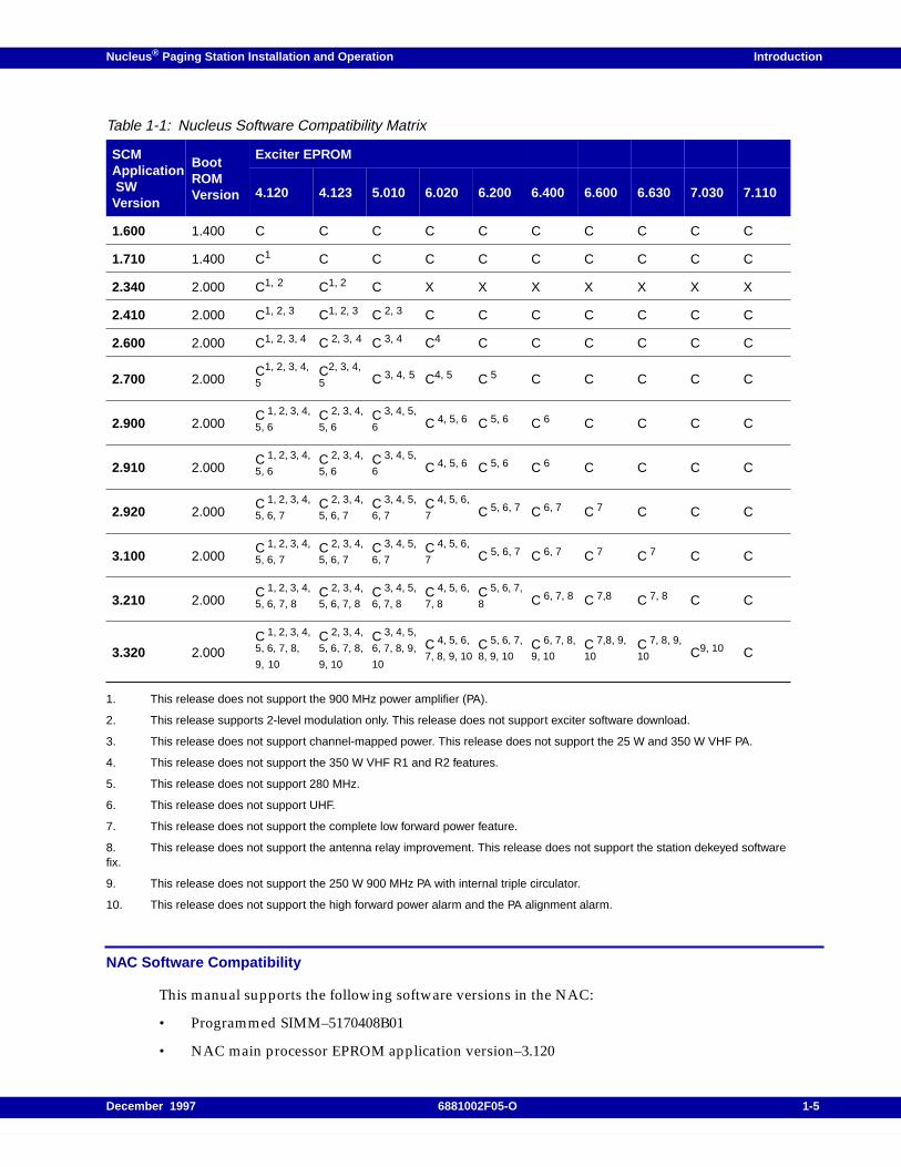
Motorola tracks compatibility for Nucleus software and makes software updates as required (see Table1-1, where C = compatible, X = incompatible, and a number references a note for the table).
Note: If the exciter accepts software download, the downloaded software is always the latest version, andcompatibility is not an issue.
Exciter version 3.100 is only compatible with SCM version 1.520 and SCM version 1.550
Exciter version 4.050 is only compatible with SCM version 1.560.
All SCM and Exciter releases are backward compatible in a simulcast area with other releases ofNucleus software in other transmitters in the same area.
1-4 6881002F05-O December 1997
Nucleus ® Paging Station Installation and Operation Introduction
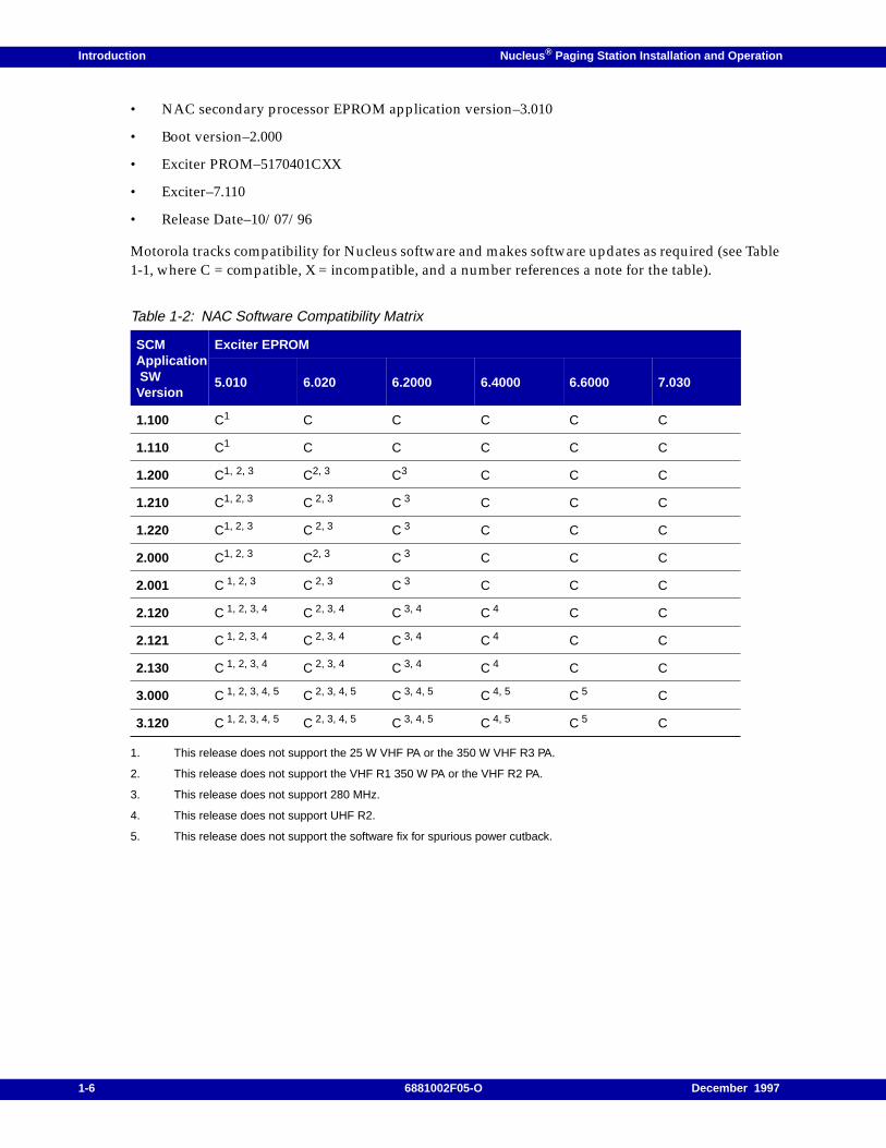
NAC Software Compatibility
This manual supports the following software versions in the NAC:
• Programmed SIMM–5170408B01
• NAC main processor EPROM application version–3.120
1. This release does not support the 900 MHz power amplifier (PA).
2. This release supports 2-level modulation only. This release does not support exciter software download.
3. This release does not support channel-mapped power. This release does not support the 25 W and 350 W VHF PA.
4. This release does not support the 350 W VHF R1 and R2 features.
5. This release does not support 280 MHz.
6. This release does not support UHF.
7. This release does not support the complete low forward power feature.
8. This release does not support the antenna relay improvement. This release does not support the station dekeyed softwarefix.
9. This release does not support the 250 W 900 MHz PA with internal triple circulator.
10. This release does not support the high forward power alarm and the PA alignment alarm.
Table 1-1: Nucleus Software Compatibility Matrix
SCMApplication SWVersion
BootROMVersion
Exciter EPROM
4.120 4.123 5.010 6.020 6.200 6.400 6.600 6.630 7.030 7.110
1.600 1.400 C C C C C C C C C C
1.710 1.400 C1 C C C C C C C C C
2.340 2.000 C1, 2 C1, 2 C X X X X X X X
2.410 2.000 C1, 2, 3 C1, 2, 3 C 2, 3 C C C C C C C
2.600 2.000 C1, 2, 3, 4 C 2, 3, 4 C 3, 4 C4 C C C C C C
2.700 2.000C1, 2, 3, 4,
5C2, 3, 4,
5 C 3, 4, 5 C4, 5 C 5 C C C C C
2.900 2.000C 1, 2, 3, 4,
5, 6C 2, 3, 4,
5, 6C 3, 4, 5,
6 C 4, 5, 6 C 5, 6 C 6 C C C C
2.910 2.000C 1, 2, 3, 4,
5, 6C 2, 3, 4,
5, 6C 3, 4, 5,
6 C 4, 5, 6 C 5, 6 C 6 C C C C
2.920 2.000C 1, 2, 3, 4,
5, 6, 7C 2, 3, 4,
5, 6, 7C 3, 4, 5,
6, 7C 4, 5, 6,
7 C 5, 6, 7 C 6, 7 C 7 C C C
3.100 2.000C 1, 2, 3, 4,
5, 6, 7C 2, 3, 4,
5, 6, 7C 3, 4, 5,
6, 7C 4, 5, 6,
7 C 5, 6, 7 C 6, 7 C 7 C 7 C C
3.210 2.000C 1, 2, 3, 4,
5, 6, 7, 8C 2, 3, 4,
5, 6, 7, 8C 3, 4, 5,
6, 7, 8C 4, 5, 6,
7, 8C 5, 6, 7,
8 C 6, 7, 8 C 7,8 C 7, 8 C C
3.320 2.000C 1, 2, 3, 4,
5, 6, 7, 8,
9, 10
C 2, 3, 4,
5, 6, 7, 8,
9, 10
C 3, 4, 5,
6, 7, 8, 9,
10
C 4, 5, 6,
7, 8, 9, 10C 5, 6, 7,
8, 9, 10C 6, 7, 8,
9, 10C 7,8, 9,
10C 7, 8, 9,
10 C9, 10 C
December 1997 6881002F05-O 1-5
Introduction Nucleus ® Paging Station Installation and Operation
• NAC secondary processor EPROM application version–3.010
• Boot version–2.000
• Exciter PROM–5170401CXX
• Exciter–7.110
• Release Date–10/07/96
Motorola tracks compatibility for Nucleus software and makes software updates as required (see Table1-1, where C = compatible, X = incompatible, and a number references a note for the table).
1. This release does not support the 25 W VHF PA or the 350 W VHF R3 PA.
2. This release does not support the VHF R1 350 W PA or the VHF R2 PA.
3. This release does not support 280 MHz.
4. This release does not support UHF R2.
5. This release does not support the software fix for spurious power cutback.
Table 1-2: NAC Software Compatibility Matrix
SCMApplication SWVersion
Exciter EPROM
5.010 6.020 6.2000 6.4000 6.6000 7.030
1.100 C1 C C C C C
1.110 C1 C C C C C
1.200 C1, 2, 3 C2, 3 C3 C C C
1.210 C1, 2, 3 C 2, 3 C 3 C C C
1.220 C1, 2, 3 C 2, 3 C 3 C C C
2.000 C1, 2, 3 C2, 3 C 3 C C C
2.001 C 1, 2, 3 C 2, 3 C 3 C C C
2.120 C 1, 2, 3, 4 C 2, 3, 4 C 3, 4 C 4 C C
2.121 C 1, 2, 3, 4 C 2, 3, 4 C 3, 4 C 4 C C
2.130 C 1, 2, 3, 4 C 2, 3, 4 C 3, 4 C 4 C C
3.000 C 1, 2, 3, 4, 5 C 2, 3, 4, 5 C 3, 4, 5 C 4, 5 C 5 C
3.120 C 1, 2, 3, 4, 5 C 2, 3, 4, 5 C 3, 4, 5 C 4, 5 C 5 C
1-6 6881002F05-O December 1997

Nucleus ® Paging Station Installation and Operation Introduction
Related Publications
For further information, see the following publications:
• RF-Baton! Transmitter Controller Installation and Operation Guide, 6880497G05
• C-NET External Network Interface Unit (NIU) Installation and Operation Guide, 6880451F10.
• External NIU Installation, 6880497G10
December 1997 6881002F05-O 1-7
Introduction Nucleus ® Paging Station Installation and Operation
Specifications
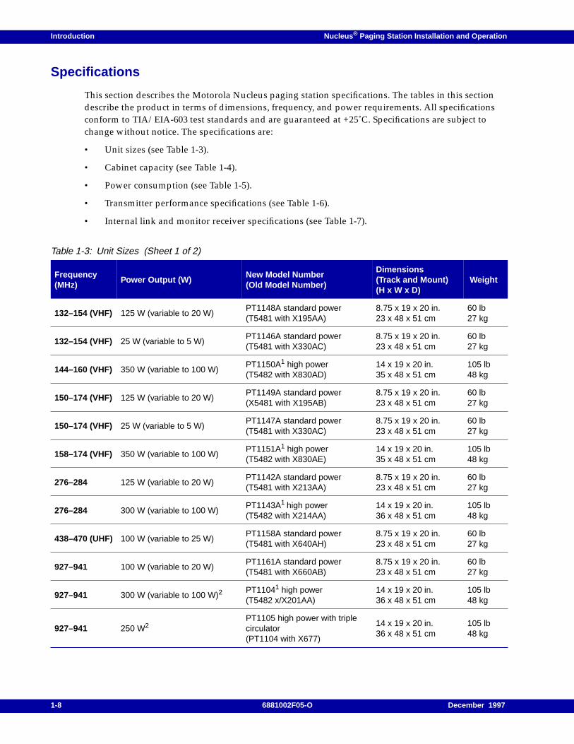
This section describes the Motorola Nucleus paging station specifications. The tables in this sectiondescribe the product in terms of dimensions, frequency, and power requirements. All specificationsconform to TIA/EIA-603 test standards and are guaranteed at +25˚C. Specifications are subject tochange without notice. The specifications are:
• Unit sizes (see Table 1-3).
• Cabinet capacity (see Table 1-4).
• Power consumption (see Table 1-5).
• Transmitter performance specifications (see Table 1-6).
• Internal link and monitor receiver specifications (see Table 1-7).
Table 1-3: Unit Sizes (Sheet 1 of 2)
Frequency(MHz)
Power Output (W)New Model Number(Old Model Number)
Dimensions(Track and Mount)(H x W x D)
Weight
132–154 (VHF) 125 W (variable to 20 W)PT1148A standard power(T5481 with X195AA)
8.75 x 19 x 20 in.23 x 48 x 51 cm
60 lb27 kg
132–154 (VHF) 25 W (variable to 5 W)PT1146A standard power(T5481 with X330AC)
8.75 x 19 x 20 in.23 x 48 x 51 cm
60 lb27 kg
144–160 (VHF) 350 W (variable to 100 W)PT1150A1 high power(T5482 with X830AD)
14 x 19 x 20 in.35 x 48 x 51 cm
105 lb48 kg
150–174 (VHF) 125 W (variable to 20 W)PT1149A standard power(X5481 with X195AB)
8.75 x 19 x 20 in.23 x 48 x 51 cm
60 lb27 kg
150–174 (VHF) 25 W (variable to 5 W)PT1147A standard power(T5481 with X330AC)
8.75 x 19 x 20 in.23 x 48 x 51 cm
60 lb27 kg
158–174 (VHF) 350 W (variable to 100 W)PT1151A1 high power(T5482 with X830AE)
14 x 19 x 20 in.35 x 48 x 51 cm
105 lb48 kg
276–284 125 W (variable to 20 W)PT1142A standard power(T5481 with X213AA)
8.75 x 19 x 20 in.23 x 48 x 51 cm
60 lb27 kg
276–284 300 W (variable to 100 W)PT1143A1 high power(T5482 with X214AA)
14 x 19 x 20 in.36 x 48 x 51 cm
105 lb48 kg
438–470 (UHF) 100 W (variable to 25 W)PT1158A standard power(T5481 with X640AH)
8.75 x 19 x 20 in.23 x 48 x 51 cm
60 lb27 kg
927–941 100 W (variable to 20 W)PT1161A standard power(T5481 with X660AB)
8.75 x 19 x 20 in.23 x 48 x 51 cm
60 lb27 kg
927–941 300 W (variable to 100 W)2PT11041 high power(T5482 x/X201AA)
14 x 19 x 20 in.36 x 48 x 51 cm
105 lb48 kg
927–941 250 W2PT1105 high power with triplecirculator(PT1104 with X677)
14 x 19 x 20 in.36 x 48 x 51 cm
105 lb48 kg
1-8 6881002F05-O December 1997
Nucleus ® Paging Station Installation and Operation Introduction
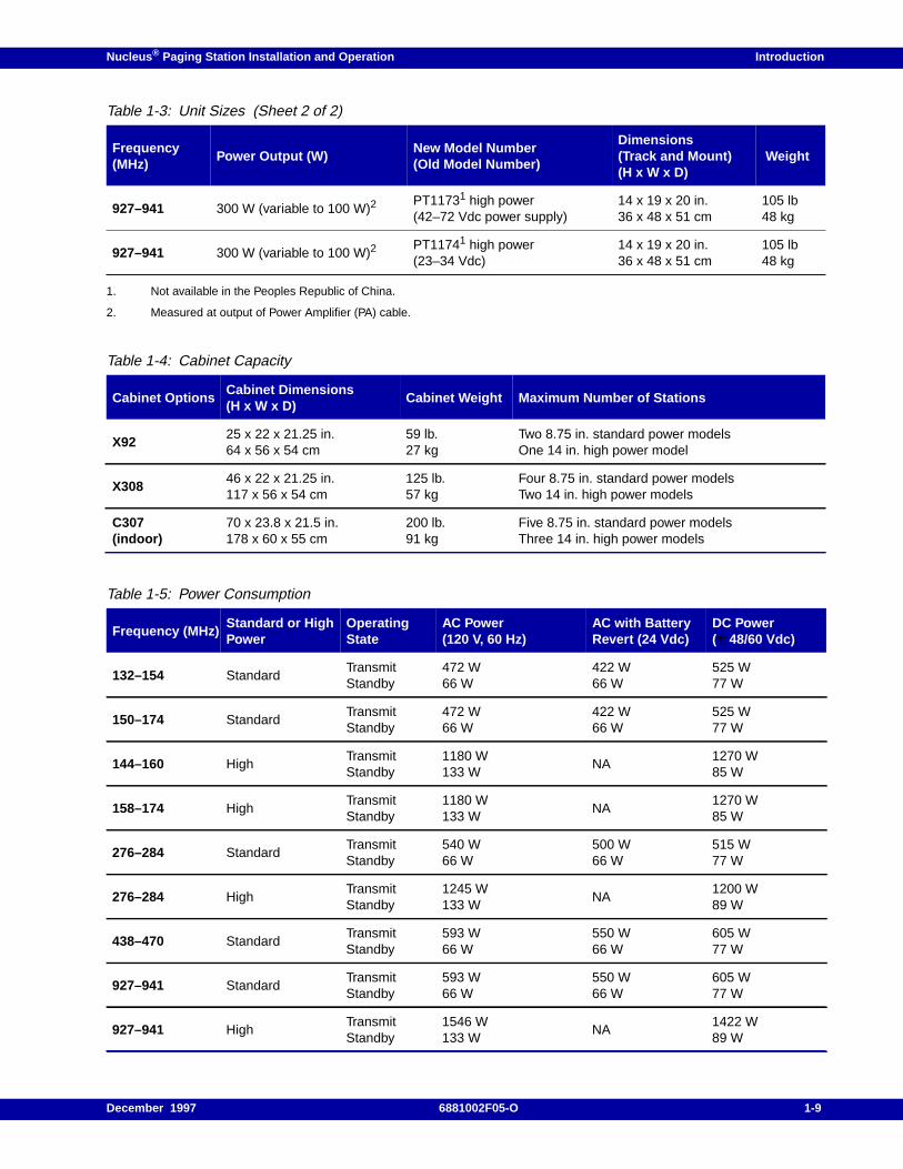
1. Not available in the Peoples Republic of China.
2. Measured at output of Power Amplifier (PA) cable.
927–941 300 W (variable to 100 W)2PT11731 high power(42–72 Vdc power supply)
14 x 19 x 20 in.36 x 48 x 51 cm
105 lb48 kg
927–941 300 W (variable to 100 W)2PT11741 high power(23–34 Vdc)
14 x 19 x 20 in.36 x 48 x 51 cm
105 lb48 kg
Table 1-4: Cabinet Capacity
Cabinet OptionsCabinet Dimensions(H x W x D)
Cabinet Weight Maximum Number of Stations
X9225 x 22 x 21.25 in.64 x 56 x 54 cm
59 lb.27 kg
Two 8.75 in. standard power modelsOne 14 in. high power model
X30846 x 22 x 21.25 in.117 x 56 x 54 cm
125 lb.57 kg
Four 8.75 in. standard power modelsTwo 14 in. high power models
C307(indoor)
70 x 23.8 x 21.5 in.178 x 60 x 55 cm
200 lb.91 kg
Five 8.75 in. standard power modelsThree 14 in. high power models
Table 1-5: Power Consumption
Frequency (MHz)Standard or HighPower
OperatingState
AC Power(120 V, 60 Hz)
AC with BatteryRevert (24 Vdc)
DC Power(± 48/60 Vdc)
132–154 StandardTransmitStandby
472 W66 W
422 W66 W
525 W77 W
150–174 StandardTransmitStandby
472 W66 W
422 W66 W
525 W77 W
144–160 HighTransmitStandby
1180 W133 W
NA1270 W85 W
158–174 HighTransmitStandby
1180 W133 W
NA1270 W85 W
276–284 StandardTransmitStandby
540 W66 W
500 W66 W
515 W77 W
276–284 HighTransmitStandby
1245 W133 W
NA1200 W89 W
438–470 StandardTransmitStandby
593 W66 W
550 W66 W
605 W77 W
927–941 StandardTransmitStandby
593 W66 W
550 W66 W
605 W77 W
927–941 HighTransmitStandby
1546 W133 W
NA1422 W89 W
Table 1-3: Unit Sizes (Sheet 2 of 2)
Frequency(MHz)
Power Output (W)New Model Number(Old Model Number)
Dimensions(Track and Mount)(H x W x D)
Weight
December 1997 6881002F05-O 1-9
Introduction Nucleus ® Paging Station Installation and Operation
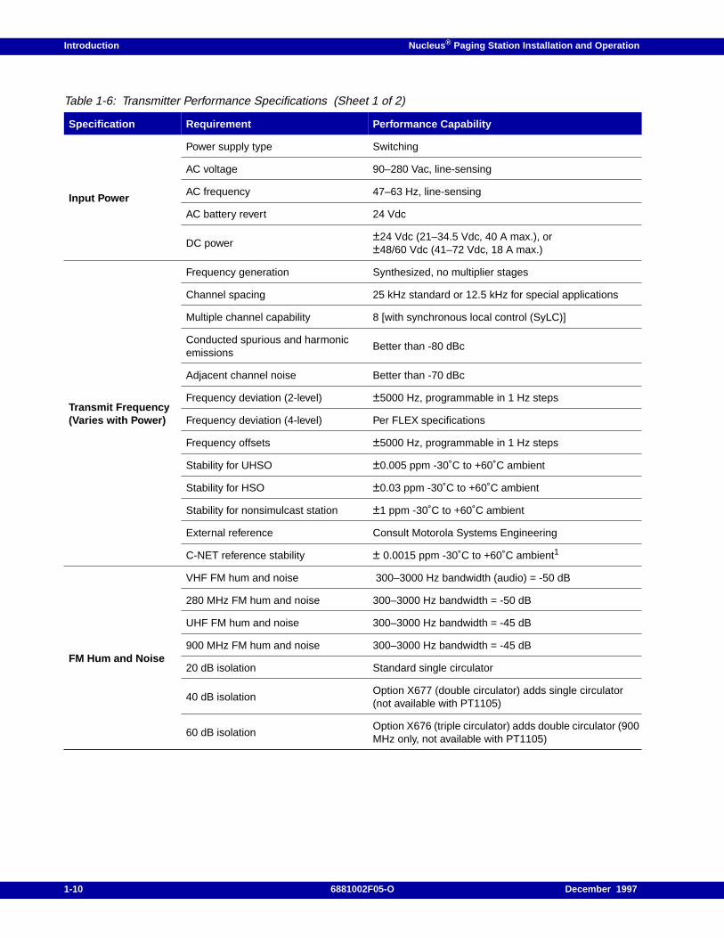
Table 1-6: Transmitter Performance Specifications (Sheet 1 of 2)
Specification Requirement Performance Capability
Input Power
Power supply type Switching
AC voltage 90–280 Vac, line-sensing
AC frequency 47–63 Hz, line-sensing
AC battery revert 24 Vdc
DC power±24 Vdc (21–34.5 Vdc, 40 A max.), or±48/60 Vdc (41–72 Vdc, 18 A max.)
Transmit Frequency(Varies with Power)
Frequency generation Synthesized, no multiplier stages
Channel spacing 25 kHz standard or 12.5 kHz for special applications
Multiple channel capability 8 [with synchronous local control (SyLC)]
Conducted spurious and harmonicemissions
Better than -80 dBc
Adjacent channel noise Better than -70 dBc
Frequency deviation (2-level) ±5000 Hz, programmable in 1 Hz steps
Frequency deviation (4-level) Per FLEX specifications
Frequency offsets ±5000 Hz, programmable in 1 Hz steps
Stability for UHSO ±0.005 ppm -30˚C to +60˚C ambient
Stability for HSO ±0.03 ppm -30˚C to +60˚C ambient
Stability for nonsimulcast station ±1 ppm -30˚C to +60˚C ambient
External reference Consult Motorola Systems Engineering
C-NET reference stability ± 0.0015 ppm -30˚C to +60˚C ambient1
FM Hum and Noise
VHF FM hum and noise 300–3000 Hz bandwidth (audio) = -50 dB
280 MHz FM hum and noise 300–3000 Hz bandwidth = -50 dB
UHF FM hum and noise 300–3000 Hz bandwidth = -45 dB
900 MHz FM hum and noise 300–3000 Hz bandwidth = -45 dB
20 dB isolation Standard single circulator
40 dB isolationOption X677 (double circulator) adds single circulator(not available with PT1105)
60 dB isolationOption X676 (triple circulator) adds double circulator (900MHz only, not available with PT1105)
1-10 6881002F05-O December 1997
Nucleus ® Paging Station Installation and Operation Introduction
1. Not available for Nucleus with Advanced Control (NAC).
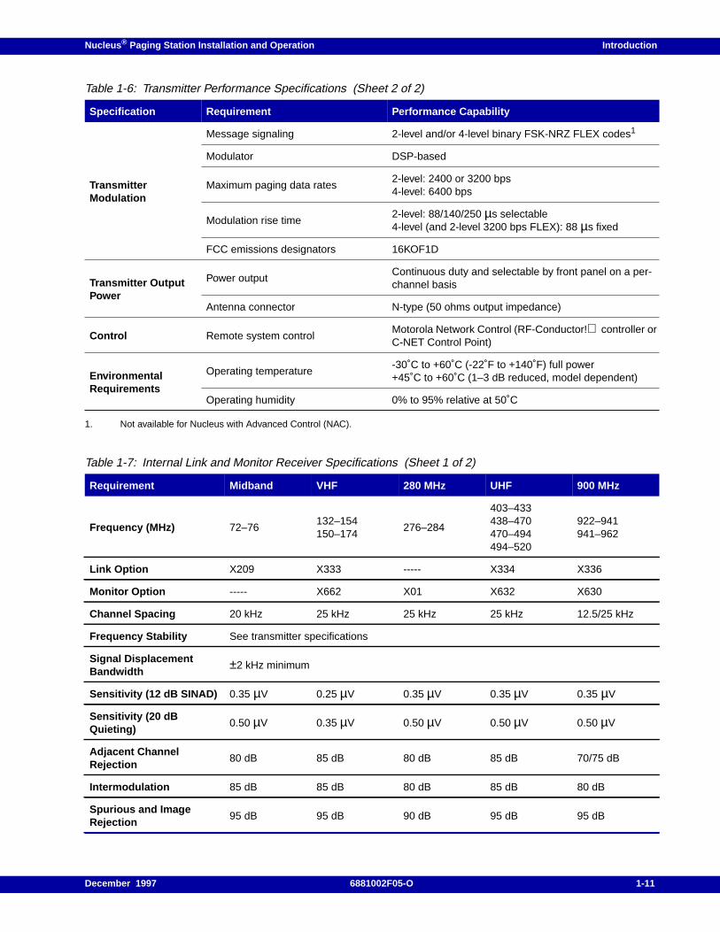
TransmitterModulation
Message signaling 2-level and/or 4-level binary FSK-NRZ FLEX codes1
Modulator DSP-based
Maximum paging data rates2-level: 2400 or 3200 bps4-level: 6400 bps
Modulation rise time2-level: 88/140/250 µs selectable4-level (and 2-level 3200 bps FLEX): 88 µs fixed
FCC emissions designators 16KOF1D
Transmitter OutputPower
Power outputContinuous duty and selectable by front panel on a per-channel basis
Antenna connector N-type (50 ohms output impedance)
Control Remote system controlMotorola Network Control (RF-Conductor! controller orC-NET Control Point)
EnvironmentalRequirements
Operating temperature-30˚C to +60˚C (-22˚F to +140˚F) full power+45˚C to +60˚C (1–3 dB reduced, model dependent)
Operating humidity 0% to 95% relative at 50˚C
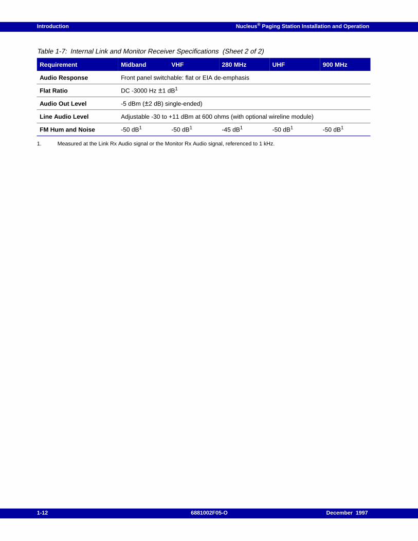
Table 1-7: Internal Link and Monitor Receiver Specifications (Sheet 1 of 2)
Requirement Midband VHF 280 MHz UHF 900 MHz
Frequency (MHz) 72–76132–154150–174
276–284
403–433438–470470–494494–520
922–941941–962
Link Option X209 X333 ----- X334 X336
Monitor Option ----- X662 X01 X632 X630
Channel Spacing 20 kHz 25 kHz 25 kHz 25 kHz 12.5/25 kHz
Frequency Stability See transmitter specifications
Signal DisplacementBandwidth
±2 kHz minimum
Sensitivity (12 dB SINAD) 0.35 µV 0.25 µV 0.35 µV 0.35 µV 0.35 µV
Sensitivity (20 dBQuieting)
0.50 µV 0.35 µV 0.50 µV 0.50 µV 0.50 µV
Adjacent ChannelRejection
80 dB 85 dB 80 dB 85 dB 70/75 dB
Intermodulation 85 dB 85 dB 80 dB 85 dB 80 dB
Spurious and ImageRejection
95 dB 95 dB 90 dB 95 dB 95 dB
Table 1-6: Transmitter Performance Specifications (Sheet 2 of 2)
Specification Requirement Performance Capability
December 1997 6881002F05-O 1-11
Introduction Nucleus ® Paging Station Installation and Operation
1. Measured at the Link Rx Audio signal or the Monitor Rx Audio signal, referenced to 1 kHz.
Audio Response Front panel switchable: flat or EIA de-emphasis
Flat Ratio DC -3000 Hz ±1 dB1
Audio Out Level -5 dBm (±2 dB) single-ended)
Line Audio Level Adjustable -30 to +11 dBm at 600 ohms (with optional wireline module)
FM Hum and Noise -50 dB1 -50 dB1 -45 dB1 -50 dB1 -50 dB1
Table 1-7: Internal Link and Monitor Receiver Specifications (Sheet 2 of 2)
Requirement Midband VHF 280 MHz UHF 900 MHz
1-12 6881002F05-O December 1997
Nucleus ® Paging Station Installation and Operation Introduction
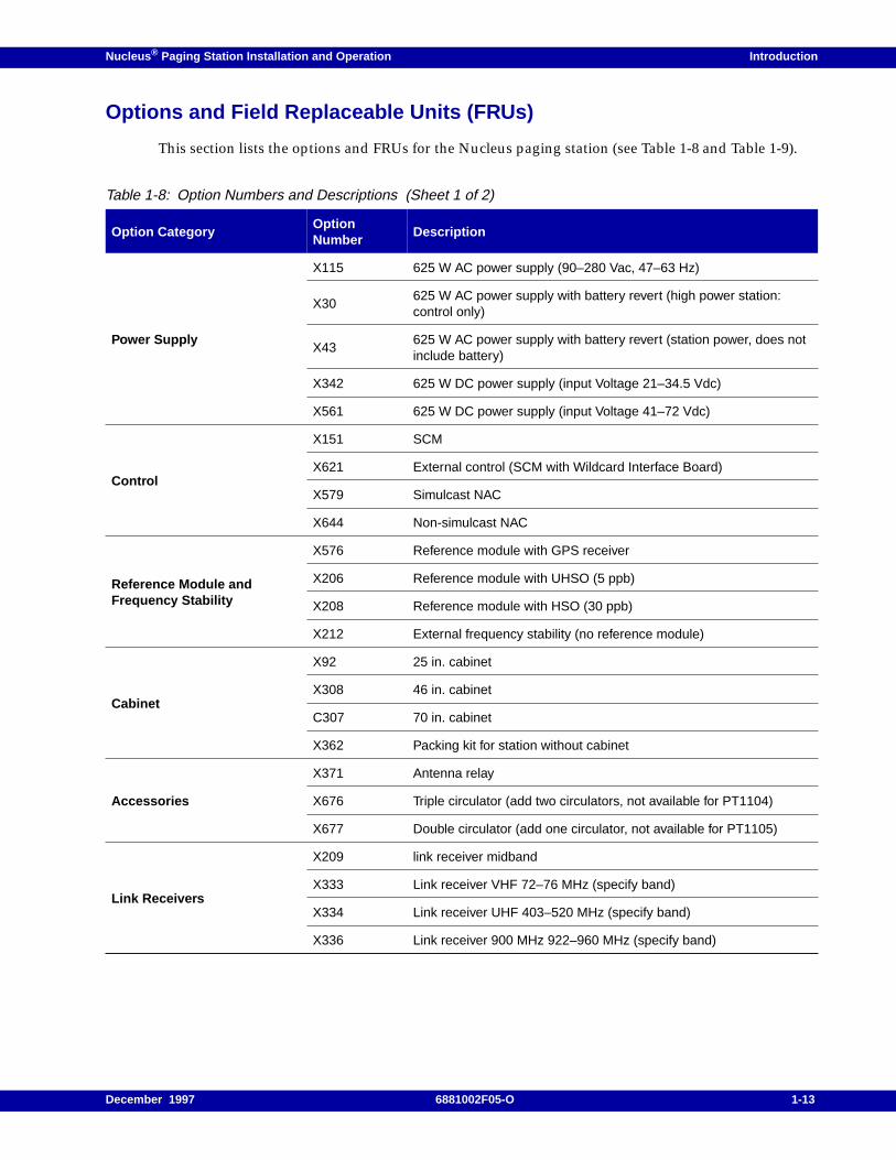
Options and Field Replaceable Units (FRUs)
This section lists the options and FRUs for the Nucleus paging station (see Table 1-8 and Table 1-9).
Table 1-8: Option Numbers and Descriptions (Sheet 1 of 2)
Option CategoryOptionNumber
Description
Power Supply
X115 625 W AC power supply (90–280 Vac, 47–63 Hz)
X30625 W AC power supply with battery revert (high power station:control only)
X43625 W AC power supply with battery revert (station power, does notinclude battery)
X342 625 W DC power supply (input Voltage 21–34.5 Vdc)
X561 625 W DC power supply (input Voltage 41–72 Vdc)
Control
X151 SCM
X621 External control (SCM with Wildcard Interface Board)
X579 Simulcast NAC
X644 Non-simulcast NAC
Reference Module andFrequency Stability
X576 Reference module with GPS receiver
X206 Reference module with UHSO (5 ppb)
X208 Reference module with HSO (30 ppb)
X212 External frequency stability (no reference module)
Cabinet
X92 25 in. cabinet
X308 46 in. cabinet
C307 70 in. cabinet
X362 Packing kit for station without cabinet
Accessories
X371 Antenna relay
X676 Triple circulator (add two circulators, not available for PT1104)
X677 Double circulator (add one circulator, not available for PT1105)
Link Receivers
X209 link receiver midband
X333 Link receiver VHF 72–76 MHz (specify band)
X334 Link receiver UHF 403–520 MHz (specify band)
X336 Link receiver 900 MHz 922–960 MHz (specify band)
December 1997 6881002F05-O 1-13
Introduction Nucleus ® Paging Station Installation and Operation
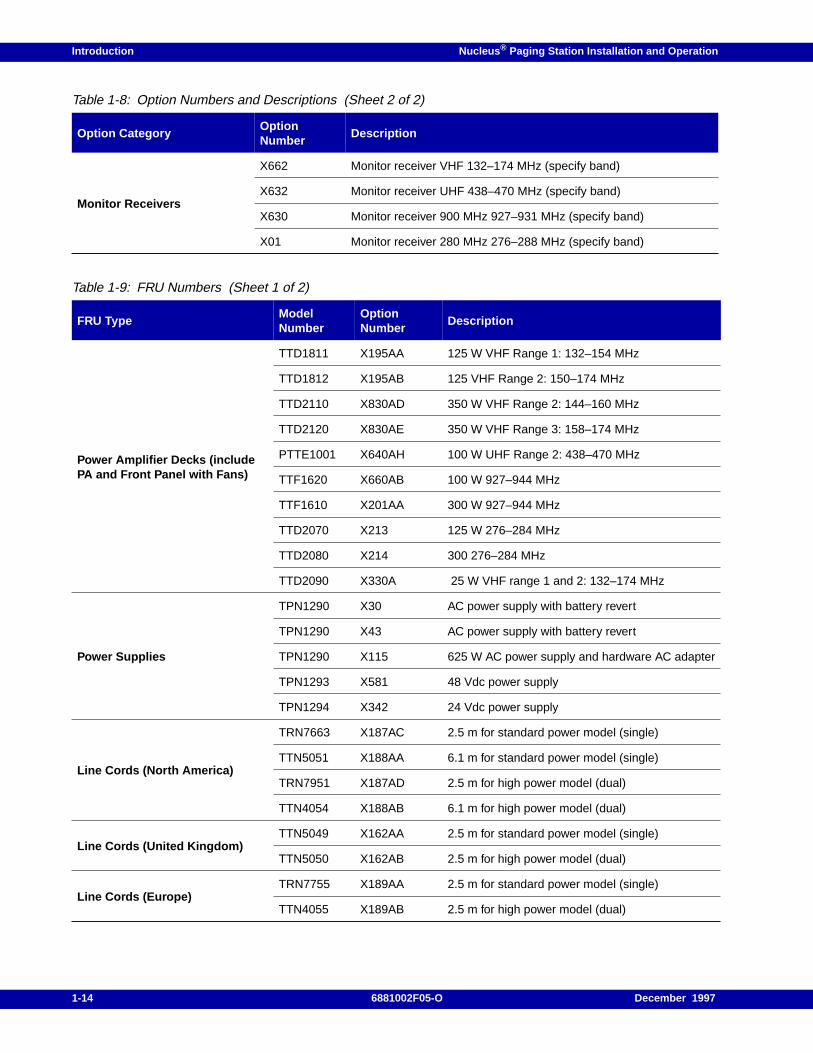
Monitor Receivers
X662 Monitor receiver VHF 132–174 MHz (specify band)
X632 Monitor receiver UHF 438–470 MHz (specify band)
X630 Monitor receiver 900 MHz 927–931 MHz (specify band)
X01 Monitor receiver 280 MHz 276–288 MHz (specify band)
Table 1-9: FRU Numbers (Sheet 1 of 2)
FRU TypeModelNumber
OptionNumber
Description
Power Amplifier Decks (includePA and Front Panel with Fans)
TTD1811 X195AA 125 W VHF Range 1: 132–154 MHz
TTD1812 X195AB 125 VHF Range 2: 150–174 MHz
TTD2110 X830AD 350 W VHF Range 2: 144–160 MHz
TTD2120 X830AE 350 W VHF Range 3: 158–174 MHz
PTTE1001 X640AH 100 W UHF Range 2: 438–470 MHz
TTF1620 X660AB 100 W 927–944 MHz
TTF1610 X201AA 300 W 927–944 MHz
TTD2070 X213 125 W 276–284 MHz
TTD2080 X214 300 276–284 MHz
TTD2090 X330A 25 W VHF range 1 and 2: 132–174 MHz
Power Supplies
TPN1290 X30 AC power supply with battery revert
TPN1290 X43 AC power supply with battery revert
TPN1290 X115 625 W AC power supply and hardware AC adapter
TPN1293 X581 48 Vdc power supply
TPN1294 X342 24 Vdc power supply
Line Cords (North America)
TRN7663 X187AC 2.5 m for standard power model (single)
TTN5051 X188AA 6.1 m for standard power model (single)
TRN7951 X187AD 2.5 m for high power model (dual)
TTN4054 X188AB 6.1 m for high power model (dual)
Line Cords (United Kingdom)TTN5049 X162AA 2.5 m for standard power model (single)
TTN5050 X162AB 2.5 m for high power model (dual)
Line Cords (Europe)TRN7755 X189AA 2.5 m for standard power model (single)
TTN4055 X189AB 2.5 m for high power model (dual)
Table 1-8: Option Numbers and Descriptions (Sheet 2 of 2)
Option CategoryOptionNumber
Description
1-14 6881002F05-O December 1997
Nucleus ® Paging Station Installation and Operation Introduction
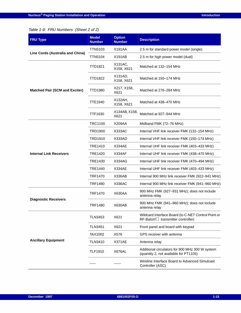
Line Cords (Australia and China)TTN5103 X191AA 2.5 m for standard power model (single)
TTN5104 X191AB 2.5 m for high power model (dual)
Matched Pair (SCM and Exciter)
TTD1821X131AC,X158, X621
Matched at 132–154 MHz
TTD1822X131AD,X158, X621
Matched at 150–174 MHz
TTD1980X217, X158,X621
Matched at 276–284 MHz
TTE1940X132AH,X158, X621
Matched at 438–470 MHz
TTF1630X134AB, X158,X621
Matched at 927–944 MHz
Internal Link Receivers
TRC1100 X209AA Midband FMK (72–76 MHz)
TRD1900 X333AC Internal VHF link receiver FMK (132–154 MHz)
TRD1910 X333AD Internal VHF link receiver FMK (150–174 MHz)
TRE1410 X334AE Internal UHF link receiver FMK (403–433 MHz)
TRE1420 X334AF Internal UHF link receiver FMK (438–470 MHz)
TRE1430 X334AG Internal UHF link receiver FMK (470–494 MHz)
TRE1440 X334AE Internal UHF link receiver FMK (403–433 MHz)
TRF1470 X336AB Internal 900 MHz link receiver FMK (922–941 MHz)
TRF1480 X336AC Internal 900 MHz link receiver FMK (941–960 MHz)
Diagnostic Receivers
TRF1470 X630AA900 MHz FMK (927–931 MHz); does not includeantenna relay
TRF1480 X630AB900 MHz FMK (941–960 MHz); does not includeantenna relay
Ancillary Equipment
TLN3453 X621Wildcard Interface Board (to C-NET Control Point orRF-Baton! transmitter controller)
TLN3451 X621 Front panel and board with keypad
TAX1002 X576 GPS receiver with antenna
TLN3410 X371AE Antenna relay
TLF1910 X676ALAdditional circulators for 900 MHz 300 W system(quantity 2, not available for PT1105)
----- ------Wireline Interface Board to Advanced SimulcastController (ASC)
Table 1-9: FRU Numbers (Sheet 2 of 2)
FRU TypeModelNumber
OptionNumber
Description
December 1997 6881002F05-O 1-15
Introduction Nucleus ® Paging Station Installation and Operation
FCC Type Acceptance Data
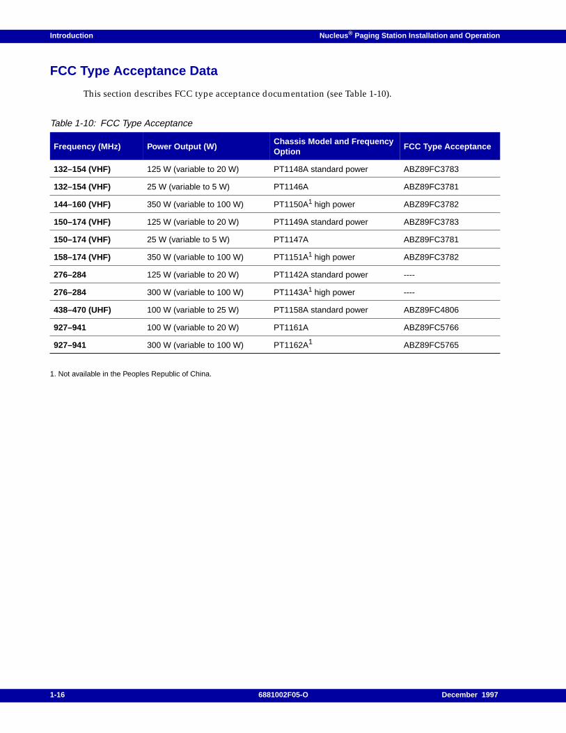
This section describes FCC type acceptance documentation (see Table 1-10).
1. Not available in the Peoples Republic of China.
Table 1-10: FCC Type Acceptance
Frequency (MHz) Power Output (W)Chassis Model and FrequencyOption
FCC Type Acceptance
132–154 (VHF) 125 W (variable to 20 W) PT1148A standard power ABZ89FC3783
132–154 (VHF) 25 W (variable to 5 W) PT1146A ABZ89FC3781
144–160 (VHF) 350 W (variable to 100 W) PT1150A1 high power ABZ89FC3782
150–174 (VHF) 125 W (variable to 20 W) PT1149A standard power ABZ89FC3783
150–174 (VHF) 25 W (variable to 5 W) PT1147A ABZ89FC3781
158–174 (VHF) 350 W (variable to 100 W) PT1151A1 high power ABZ89FC3782
276–284 125 W (variable to 20 W) PT1142A standard power ----
276–284 300 W (variable to 100 W) PT1143A1 high power ----
438–470 (UHF) 100 W (variable to 25 W) PT1158A standard power ABZ89FC4806
927–941 100 W (variable to 20 W) PT1161A ABZ89FC5766
927–941 300 W (variable to 100 W) PT1162A1 ABZ89FC5765
1-16 6881002F05-O December 1997

Nucleus ® Paging Station Installation and Operation / Chapter 2
Nucleus Paging Station Description 2
This chapter briefly describes the operation of the Nucleus paging station and the Nucleus pagingstation with Advanced Control (NAC). This chapter contains the following information:
General Description, 2-2
SCM, 2-3Transmitter Control, 2-3Receiver Communication, 2-4
Exciter, 2-6
Power Amplifier, 2-7PA for a Standard Power Nucleus Paging Station, 2-7PA for a High Power Nucleus Paging Station, 2-8
Power Supply, 2-10
Receiver Module, 2-11
Reference Modules, 2-13Reference Module with Global Positioning System (GPS) Receiver, 2-13Reference Module with an Oscillator, 2-13
Transmitter Controllers, 2-15Wildcard Interface Board for RF-B! Transmitter Controllers, 2-15Internal Network Interface Unit (NIU), 2-16Wireline Interface Board for NAC, 2-16
December 1997 6881002F05-O 2-1
Nucleus Paging Station Description Nucleus ® Paging Station Installation and Operation
General Description
A Nucleus paging station consists of the following elements:
• Station Control Module (SCM)–controls the station, and processes inputs from and displays tothe SCM front panel.
• Exciter–provides the carrier frequency for the transmitter.
• Power Amplifier (PA)–combines the messaging data stream with the carrier frequency, enhancesthe signal, and sends it to the antenna.
• Receiver–processes received RF signals for use by the SCM for a monitor receiver.
• Reference module–provides a known reference signal to stabilize transmitter output.
• Transmitter controller–provides an interface to the network control device. The transmittercontroller is one of the following:
– RF-Baton! (RF-B!) transmitter controller
– Internal Network Interface Unit (NIU)
– External NIU
A NAC paging station consists of the following elements:
• NAC Control Module–controls the station, and processes inputs from and displays to the NACfront panel.
• Exciter–provides the carrier frequency for the transmitter.
• PA–combines the messaging data stream with the carrier frequency, enhances the signal, andsends it to the antenna.
• Receiver–processes received RF signals for use by the SCM for a monitor receiver.
• Reference module–provides a known reference signal to stabilize transmitter output.
• Nucleus Advanced Control (NAC)–provides an interface to the network control device.
Note: The NAC uses a special mid-tier version of the SCM.
This chapter describes these elements.
2-2 6881002F05-O December 1997
Nucleus ® Paging Station Installation and Operation Nucleus Paging Station Description
SCM
This section describes the SCM. The SCM has two functions:
• Controls the transmitter
• Maintains communication with a receiver
This section describes both functions briefly.
Transmitter Control
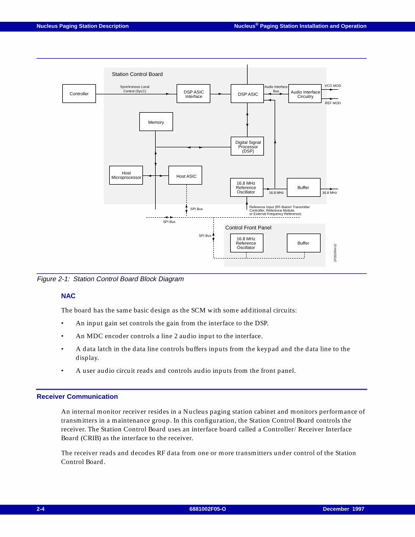
The SCM consists of an SCM front panel and a Station Control Board (see Figure 2-1).
The NAC consists of a NAC front panel and a NAC board.
Each front panel consists of a 15–pushbutton keypad and a light-emitting diode (LED) display. Anoperator, technician, or installer enters commands and configuration data for the transmitter throughthe keypad and confirms data on the LED display.
Note: For a NAC station, the operator, technician, or installer can also use a terminal connected to the NAC.
SCM
The SCM contains a digital signal processor (DSP), a DSP application-specific integrated circuit (DSPASIC), and an ASIC interface. This series of circuits translates messaging data from the transmittercontroller into modulation signals.
The DSP ASIC receives reference signals from a 16.8 MHz reference oscillator. The reference signalpasses to a buffer and then to an exciter. The digitized output signal passes to the audio interfacecircuitry (AIC). The AIC converts the digitized signal to analog, performs level-shifting, and amplifiesthe signal. The signal passes to a reconstruction filter. The output consists of two signals:
• VCO Mod, which controls the impulse response of the Exciter
• Ref Mod, which modulates the reference frequency for long-term deviation accuracy
The DSP also contains a splatter filter to prevent the transmit signal from interfering with adjacenttransmit channels. This feature matches the output of the Nucleus paging station with other paging(or messaging) stations in a simulcast system. An option on the front panel selects the appropriatesplatter filter (88 µs, 140 µs, 160 µs, or 250 µs).
The host microprocessor controls messaging. The host microprocessor reads Nucleus paging stationsoftware and configuration data from memory. It uses this information to manage messaging. Anexample is the power applied to the channel that carries the message. The microprocessor exchangesaddress and data with the host ASIC.
The host ASIC communicates with memory and the SCM front panel through a serial peripheralinterface (SPI) bus. The SPI bus communicates with the other modules on the backplane.
December 1997 6881002F05-O 2-3
Nucleus Paging Station Description Nucleus ® Paging Station Installation and Operation
Figure 2-1: Station Control Board Block Diagram
NAC
The board has the same basic design as the SCM with some additional circuits:
• An input gain set controls the gain from the interface to the DSP.
• An MDC encoder controls a line 2 audio input to the interface.
• A data latch in the data line controls buffers inputs from the keypad and the data line to thedisplay.
• A user audio circuit reads and controls audio inputs from the front panel.
Receiver Communication
An internal monitor receiver resides in a Nucleus paging station cabinet and monitors performance oftransmitters in a maintenance group. In this configuration, the Station Control Board controls thereceiver. The Station Control Board uses an interface board called a Controller/Receiver InterfaceBoard (CRIB) as the interface to the receiver.
The receiver reads and decodes RF data from one or more transmitters under control of the StationControl Board.
Controller
Memory
DSP ASICInterface DSP ASIC Audio Interface
Circuitry
Digital SignalProcessor
(DSP)
HostMicroprocessor Host ASIC
Buffer
16.8 MHzReferenceOscillator
Buffer
Synchronous LocalControl (SyLC)
Audio InterfaceBus
VCO MOD
REF MOD
16.8 MHz 16.8 MHz
16.8 MHzReferenceOscillator
Reference Input (RF-Baton! TransmitterController, Reference Module, or External Frequency Reference)
SPI Bus
SPI Bus
SPI Bus
Control Front Panel
Station Control Board
2F05
SR
H-0
2
2-4 6881002F05-O December 1997
Nucleus ® Paging Station Installation and Operation Nucleus Paging Station Description
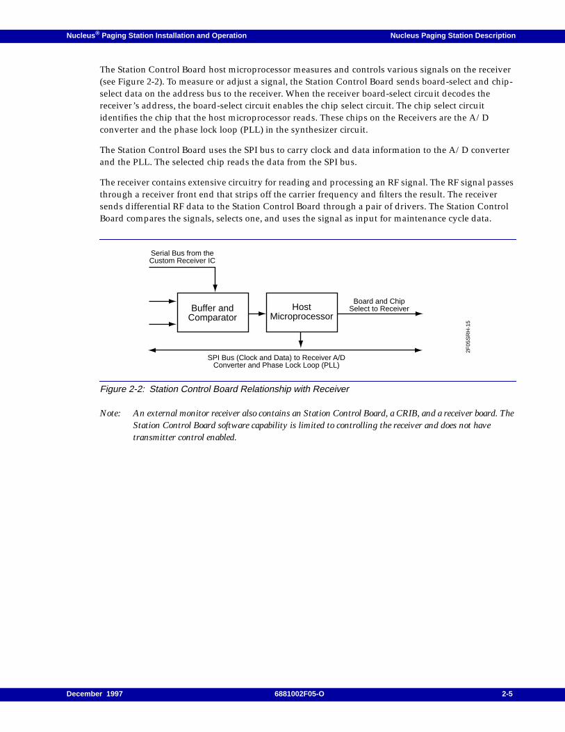
The Station Control Board host microprocessor measures and controls various signals on the receiver(see Figure 2-2). To measure or adjust a signal, the Station Control Board sends board-select and chip-select data on the address bus to the receiver. When the receiver board-select circuit decodes thereceiver’s address, the board-select circuit enables the chip select circuit. The chip select circuitidentifies the chip that the host microprocessor reads. These chips on the Receivers are the A/Dconverter and the phase lock loop (PLL) in the synthesizer circuit.
The Station Control Board uses the SPI bus to carry clock and data information to the A/D converterand the PLL. The selected chip reads the data from the SPI bus.
The receiver contains extensive circuitry for reading and processing an RF signal. The RF signal passesthrough a receiver front end that strips off the carrier frequency and filters the result. The receiversends differential RF data to the Station Control Board through a pair of drivers. The Station ControlBoard compares the signals, selects one, and uses the signal as input for maintenance cycle data.
Figure 2-2: Station Control Board Relationship with Receiver
Note: An external monitor receiver also contains an Station Control Board, a CRIB, and a receiver board. TheStation Control Board software capability is limited to controlling the receiver and does not havetransmitter control enabled.
Buffer andComparator
HostMicroprocessor
Serial Bus from theCustom Receiver IC
Board and ChipSelect to Receiver
SPI Bus (Clock and Data) to Receiver A/DConverter and Phase Lock Loop (PLL)
2F05
SR
H-1
5
December 1997 6881002F05-O 2-5
Nucleus Paging Station Description Nucleus ® Paging Station Installation and Operation
Exciter
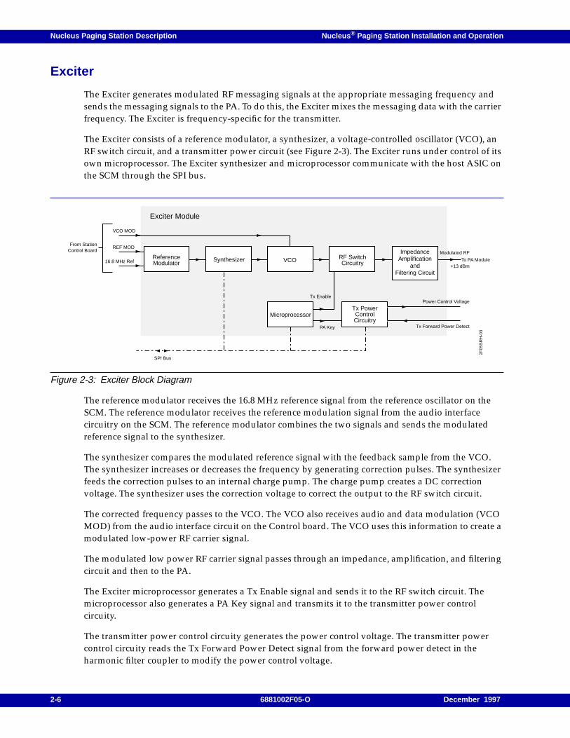
The Exciter generates modulated RF messaging signals at the appropriate messaging frequency andsends the messaging signals to the PA. To do this, the Exciter mixes the messaging data with the carrierfrequency. The Exciter is frequency-specific for the transmitter.
The Exciter consists of a reference modulator, a synthesizer, a voltage-controlled oscillator (VCO), anRF switch circuit, and a transmitter power circuit (see Figure 2-3). The Exciter runs under control of itsown microprocessor. The Exciter synthesizer and microprocessor communicate with the host ASIC onthe SCM through the SPI bus.
Figure 2-3: Exciter Block Diagram
The reference modulator receives the 16.8 MHz reference signal from the reference oscillator on theSCM. The reference modulator receives the reference modulation signal from the audio interfacecircuitry on the SCM. The reference modulator combines the two signals and sends the modulatedreference signal to the synthesizer.
The synthesizer compares the modulated reference signal with the feedback sample from the VCO.The synthesizer increases or decreases the frequency by generating correction pulses. The synthesizerfeeds the correction pulses to an internal charge pump. The charge pump creates a DC correctionvoltage. The synthesizer uses the correction voltage to correct the output to the RF switch circuit.
The corrected frequency passes to the VCO. The VCO also receives audio and data modulation (VCOMOD) from the audio interface circuit on the Control board. The VCO uses this information to create amodulated low-power RF carrier signal.
The modulated low power RF carrier signal passes through an impedance, amplification, and filteringcircuit and then to the PA.
The Exciter microprocessor generates a Tx Enable signal and sends it to the RF switch circuit. Themicroprocessor also generates a PA Key signal and transmits it to the transmitter power controlcircuity.
The transmitter power control circuity generates the power control voltage. The transmitter powercontrol circuity reads the Tx Forward Power Detect signal from the forward power detect in theharmonic filter coupler to modify the power control voltage.
ReferenceModulator
Synthesizer VCO
MicroprocessorTx PowerControlCircuitry
RF SwitchCircuitry
ImpedanceAmplification
andFiltering Circuit
Tx EnablePower Control Voltage
Modulated RF
+13 dBm
Tx Forward Power DetectPA Key
SPI Bus
VCO MOD
REF MOD
16.8 MHz Ref
2F05
SR
H-0
3
To PA Module
From StationControl Board
Exciter Module
2-6 6881002F05-O December 1997
Nucleus ® Paging Station Installation and Operation Nucleus Paging Station Description
Power Amplifier
The PA takes the modulated RF messaging signal and amplifies it in preparation for transmission. Thestructure of the PA depends on the station power level:
• Standard power Nucleus paging station (100 to 135 W)
• High power Nucleus paging station (250 to 300 W)
The output power level for the PA (at full power) varies with the frequency ranges for the PA, theExciter, and the transmitter (see Table 2-1).
In addition to the standard circulator installed in all Nucleus paging stations, two types of optionalcirculators are also available:
• External circulators–installed over the backplane on the Nucleus paging station. Motorola offerstwo levels:
– Double circulator, available for standard power and high power stations
– Triple circulator, available for high power stations only
• Internal circulator–installed inside the high power Nucleus paging station PA.
PA for a Standard Power Nucleus Paging Station
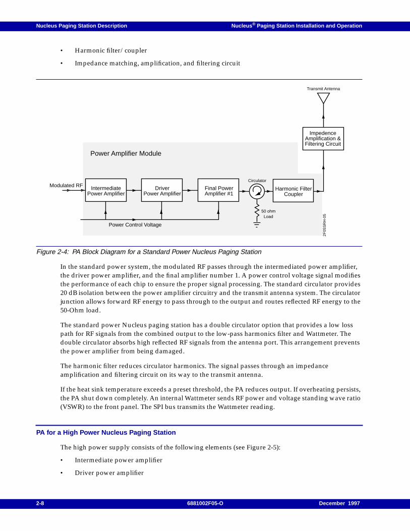
The standard PA consists of the following elements (see Figure 2-4):
• Intermediate power amplifier
• Driver power amplifier
• Final power amplifier
• Standard circulator
Table 2-1: Frequencies for PAs with Exciter and Transmit Frequencies
PA (Full Power) PA Frequency RangeExciter FrequencyRange
Transmit FrequencyRange
125 W (VHF)132 to 154 MHz 132 to 154 MHz 132 to 154 MHz
150 to 174 MHz 150 to 174 MHz 150 to 174 MHz
300 W (VHF)
144 to 160 MHz 132 to 154 MHz 144 to 154 MHz
144 to 160 MHz 150 to 174 MHz 150 to 160 MHz
157 to 174 MHz 150 to 174 MHz 157 to 174 MHz
125 W (280 MHz) 276 to 286 MHz 276 to 286 MHz 276 to 286 MHz
300 W (280 MHz) 276 to 286 MHz 276 to 286 MHz 276 to 286 MHz
100 W (UHF) 438 to 470 MHz 438 to 470 MHz 438 to 470 MHz
100 W (900 MHz) 927 to 941 MHz 927 to 941 MHz 927 to 941 MHz
300 W (900 MHz) 927 to 941 MHz 927 to 941 MHz 927 to 941 MHz
December 1997 6881002F05-O 2-7
Nucleus Paging Station Description Nucleus ® Paging Station Installation and Operation
• Harmonic filter/coupler
• Impedance matching, amplification, and filtering circuit
Figure 2-4: PA Block Diagram for a Standard Power Nucleus Paging Station
In the standard power system, the modulated RF passes through the intermediated power amplifier,the driver power amplifier, and the final amplifier number 1. A power control voltage signal modifiesthe performance of each chip to ensure the proper signal processing. The standard circulator provides20 dB isolation between the power amplifier circuitry and the transmit antenna system. The circulatorjunction allows forward RF energy to pass through to the output and routes reflected RF energy to the50-Ohm load.
The standard power Nucleus paging station has a double circulator option that provides a low losspath for RF signals from the combined output to the low-pass harmonics filter and Wattmeter. Thedouble circulator absorbs high reflected RF signals from the antenna port. This arrangement preventsthe power amplifier from being damaged.
The harmonic filter reduces circulator harmonics. The signal passes through an impedanceamplification and filtering circuit on its way to the transmit antenna.
If the heat sink temperature exceeds a preset threshold, the PA reduces output. If overheating persists,the PA shut down completely. An internal Wattmeter sends RF power and voltage standing wave ratio(VSWR) to the front panel. The SPI bus transmits the Wattmeter reading.
PA for a High Power Nucleus Paging Station
The high power supply consists of the following elements (see Figure 2-5):
• Intermediate power amplifier
• Driver power amplifier
Circulator
50 ohmLoad
Transmit Antenna
2F05
SR
H-0
5
Power Amplifier Module
Harmonic FilterCoupler
ImpedenceAmplification &Filtering Circuit
Modulated RF
Power Control Voltage
IntermediatePower Amplifier
DriverPower Amplifier
Final PowerAmplifier #1
2-8 6881002F05-O December 1997
Nucleus ® Paging Station Installation and Operation Nucleus Paging Station Description
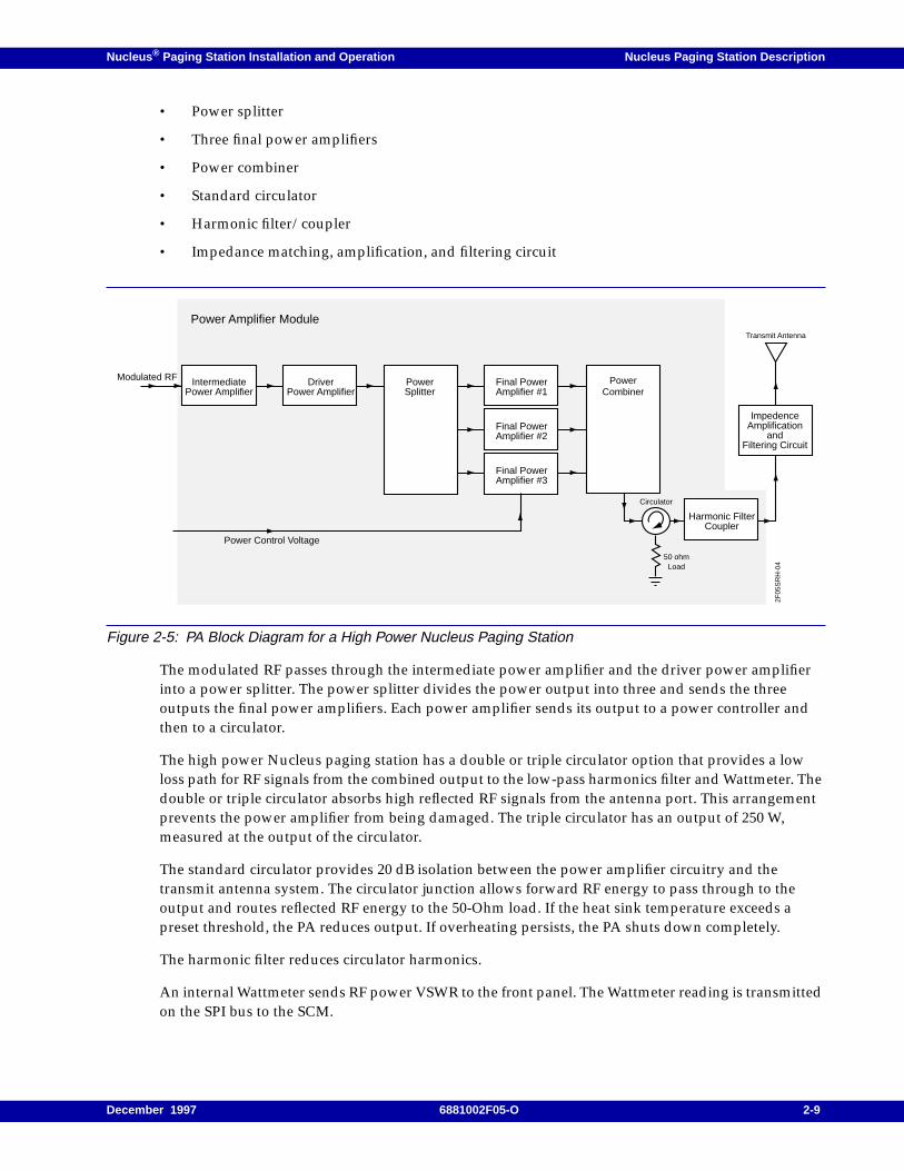
• Power splitter
• Three final power amplifiers
• Power combiner
• Standard circulator
• Harmonic filter/coupler
• Impedance matching, amplification, and filtering circuit
Figure 2-5: PA Block Diagram for a High Power Nucleus Paging Station
The modulated RF passes through the intermediate power amplifier and the driver power amplifierinto a power splitter. The power splitter divides the power output into three and sends the threeoutputs the final power amplifiers. Each power amplifier sends its output to a power controller andthen to a circulator.
The high power Nucleus paging station has a double or triple circulator option that provides a lowloss path for RF signals from the combined output to the low-pass harmonics filter and Wattmeter. Thedouble or triple circulator absorbs high reflected RF signals from the antenna port. This arrangementprevents the power amplifier from being damaged. The triple circulator has an output of 250 W,measured at the output of the circulator.
The standard circulator provides 20 dB isolation between the power amplifier circuitry and thetransmit antenna system. The circulator junction allows forward RF energy to pass through to theoutput and routes reflected RF energy to the 50-Ohm load. If the heat sink temperature exceeds apreset threshold, the PA reduces output. If overheating persists, the PA shuts down completely.
The harmonic filter reduces circulator harmonics.
An internal Wattmeter sends RF power VSWR to the front panel. The Wattmeter reading is transmittedon the SPI bus to the SCM.
IntermediatePower Amplifier
DriverPower Amplifier
Final PowerAmplifier #1
Circulator
50 ohmLoad
Transmit Antenna
2F05
SR
H-0
4
Power Amplifier Module
PowerSplitter
Final PowerAmplifier #2
Final PowerAmplifier #3
PowerCombiner
Harmonic FilterCoupler
ImpedenceAmplification
andFiltering Circuit
Modulated RF
Power Control Voltage
December 1997 6881002F05-O 2-9
Nucleus Paging Station Description Nucleus ® Paging Station Installation and Operation
Power Supply
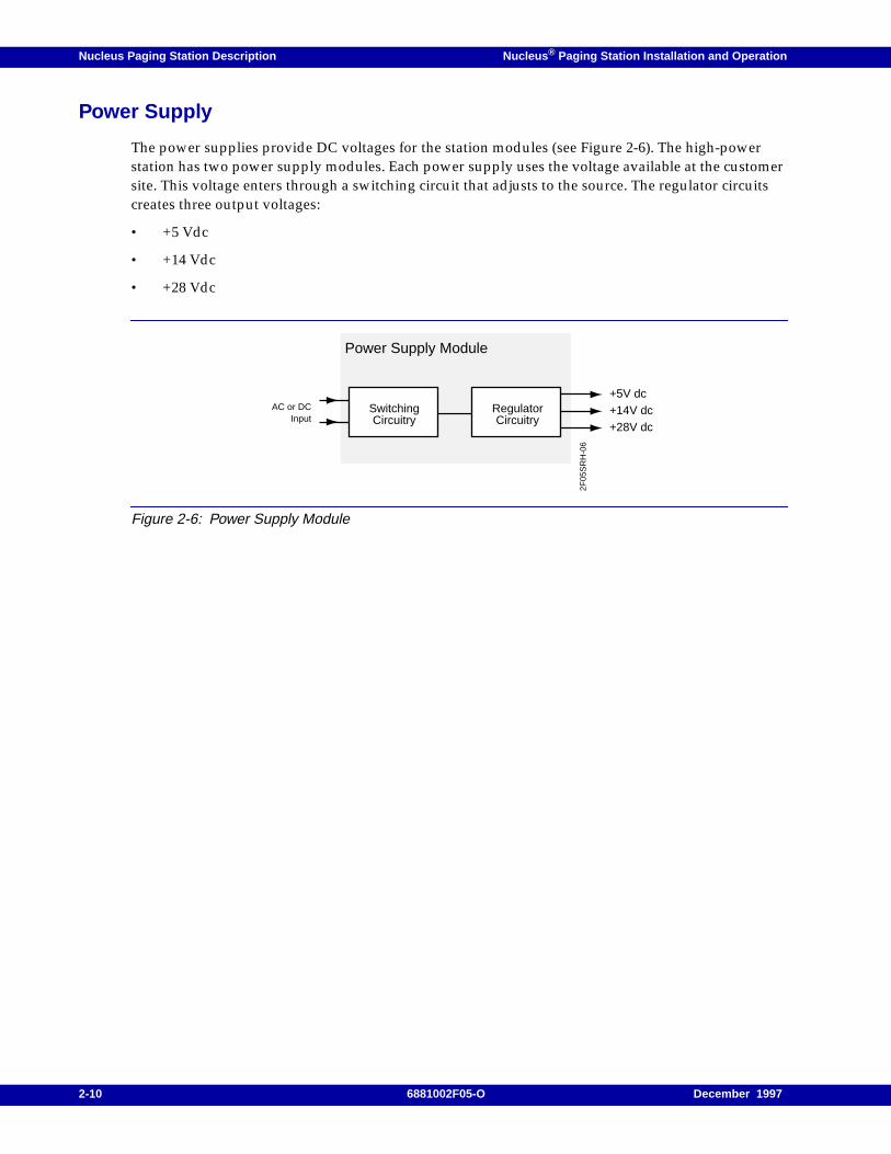
The power supplies provide DC voltages for the station modules (see Figure 2-6). The high-powerstation has two power supply modules. Each power supply uses the voltage available at the customersite. This voltage enters through a switching circuit that adjusts to the source. The regulator circuitscreates three output voltages:
• +5 Vdc
• +14 Vdc
• +28 Vdc
Figure 2-6: Power Supply Module
AC or DCInput
Power Supply Module
SwitchingCircuitry
RegulatorCircuitry
+5V dc+14V dc+28V dc
2F05
SR
H-0
6
2-10 6881002F05-O December 1997
Nucleus ® Paging Station Installation and Operation Nucleus Paging Station Description
Receiver Module
The Nucleus paging station and the NAC paging station use a receiver in either of two ways:
• As a monitor receiver to monitor the transmissions of the transmitters in one or moremaintenance groups
• As a link receiver, to receive messaging data and control from a link transmitter.
The installer configures the receiver module as a link receiver or a monitor receiver from the frontpanel. The receiver module is located in the paging station cage. It consists of the following items:
• Receiver board
• Preselector
• Receiver front panel
• CRIB mounted on the SCB
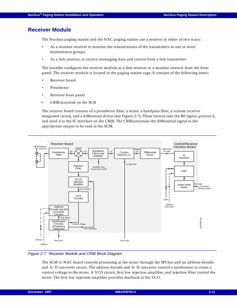
The receiver board consists of a preselector filter, a mixer, a bandpass filter, a custom receiverintegrated circuit, and a differential driver (see Figure 2-7). These circuits take the RF signal, process it,and send it to the IC interface on the CRIB. The CRIB processes the differential signal to theappropriate output to be read at the SCM.
Figure 2-7: Receiver Module and CRIB Block Diagram
The SCM or NAC board controls processing at the mixer through the SPI bus and an address decodeand A/D converter circuit. The address decode and A/D converter control a synthesizer to create acontrol voltage to the mixer. A VCO circuit, first low injection amplifier, and injection filter control themixer. The first low injection amplifier provides feedback to the VCO.
PreselectorFilter
AddressDecode and A/D
ConverterCircuitry
SynthesizerCircuitry
(FrequencySelection)
BandpassFilters andAmplifier
InjectionFilter
1st LOInjectionAmplifier
VCOCircuitry
CustomReceiver IC
DifferentialDriver IC
Interface
DSP
Audio MuteGates
MIXER
I-FRF
ReceiveAntenna
Chip Select
Control Voltage
VCO Feedback
1st LO Input
2.1 MHz Ref
From NACFrom NAC
Address
SPI Bus
Amplifier GainControl (from SCB)
I-FDigital
I-FDifferential
Rx Data
Receiver Board Control/ReceiverInterface Board
AddressFrom NAC
Rx Audio
Data
To WirelineInterface Board
2F05
SR
H-1
6
December 1997 6881002F05-O 2-11

Nucleus Paging Station Description Nucleus ® Paging Station Installation and Operation
The CRIB receives the differential Rx data at an IC interface and passes the signal to a DSP. The DSPreceives address and data from the transmitter controller. When the SCM requests the data, the DSPsends the Rx audio to the SCM.
2-12 6881002F05-O December 1997
Nucleus ® Paging Station Installation and Operation Nucleus Paging Station Description
Reference Modules
This section describes reference modules. Nucleus and NAC paging stations use two referencemodules:
• Reference module with GPS receiver (used only for stations with internal NIUs)
• Reference module with oscillator (used for stations without internal NIUs)
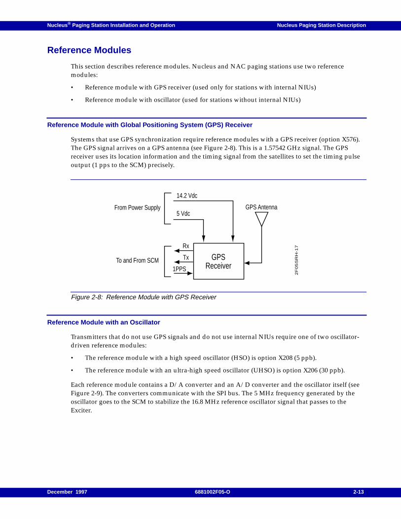
Reference Module with Global Positioning System (GPS) Receiver
Systems that use GPS synchronization require reference modules with a GPS receiver (option X576).The GPS signal arrives on a GPS antenna (see Figure 2-8). This is a 1.57542 GHz signal. The GPSreceiver uses its location information and the timing signal from the satellites to set the timing pulseoutput (1 pps to the SCM) precisely.
Figure 2-8: Reference Module with GPS Receiver
Reference Module with an Oscillator
Transmitters that do not use GPS signals and do not use internal NIUs require one of two oscillator-driven reference modules:
• The reference module with a high speed oscillator (HSO) is option X208 (5 ppb).
• The reference module with an ultra-high speed oscillator (UHSO) is option X206 (30 ppb).
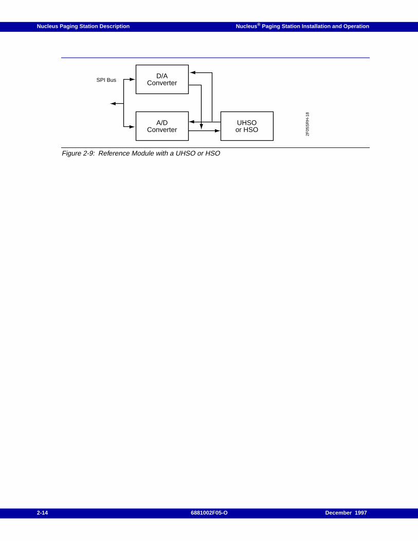
Each reference module contains a D/A converter and an A/D converter and the oscillator itself (seeFigure 2-9). The converters communicate with the SPI bus. The 5 MHz frequency generated by theoscillator goes to the SCM to stabilize the 16.8 MHz reference oscillator signal that passes to theExciter.
GPSReceiver
5 Vdc
Rx
Tx
1PPS
14.2 Vdc
GPS Antenna
2F
05S
RH
-17
From Power Supply
To and From SCM
December 1997 6881002F05-O 2-13
Nucleus Paging Station Description Nucleus ® Paging Station Installation and Operation
Figure 2-9: Reference Module with a UHSO or HSO
D/AConverter
A/DConverter
UHSOor HSO
2F05
SR
H-1
8
SPI Bus
2-14 6881002F05-O December 1997
Nucleus ® Paging Station Installation and Operation Nucleus Paging Station Description
Transmitter Controllers
This section describes Nucleus and NAC paging stations transmitter controllers. The transmittercontrollers and their interfaces include the following:
• The WIB, installed in Nucleus paging stations, use external RF-B! transmitter controllers orexternal NIUs.
• The internal NIU, installed in the Nucleus paging station, use a direct interconnect with the SCM.
• The Nucleus Advanced Control (NAC) and a WIB, installed in the NAC paging station,communicate with the Motorola Advanced Simulcast Controller (ASC).
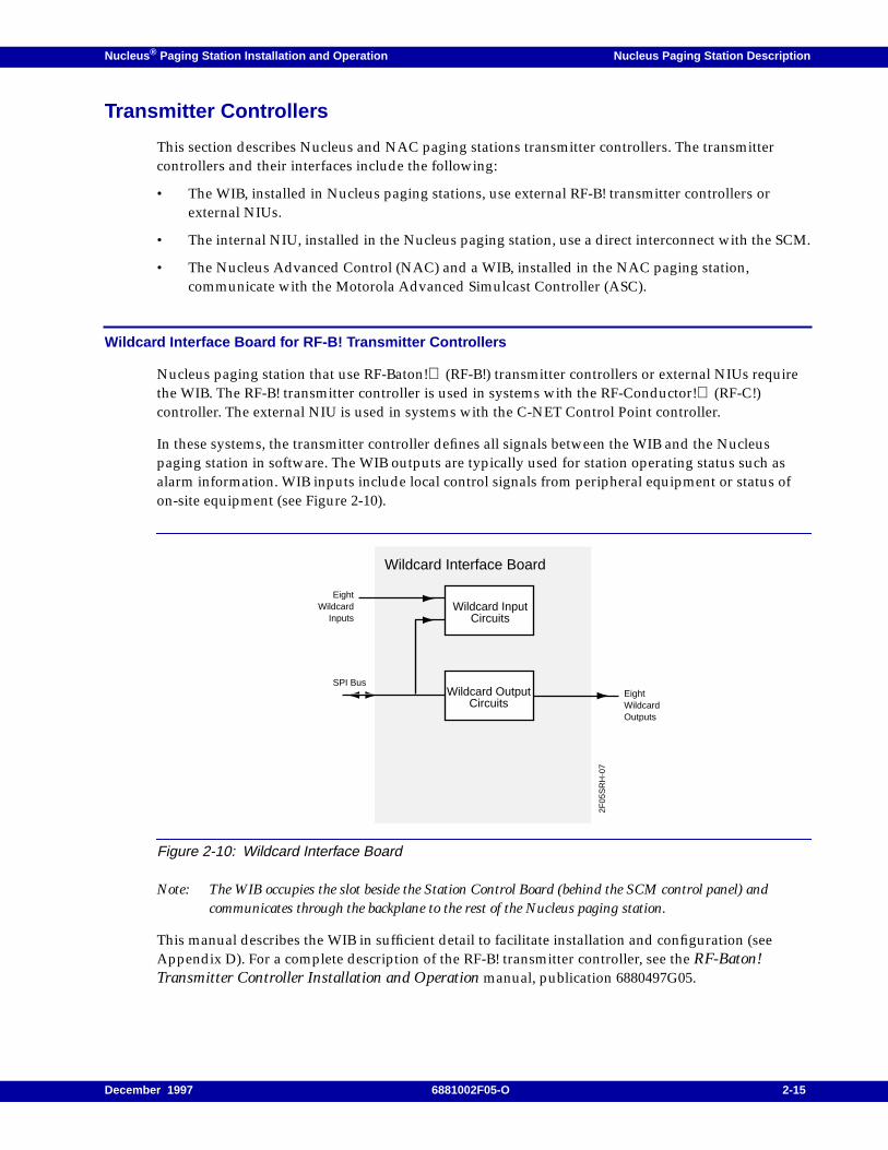
Wildcard Interface Board for RF-B! Transmitter Controllers
Nucleus paging station that use RF-Baton! (RF-B!) transmitter controllers or external NIUs requirethe WIB. The RF-B! transmitter controller is used in systems with the RF-Conductor! (RF-C!)controller. The external NIU is used in systems with the C-NET Control Point controller.
In these systems, the transmitter controller defines all signals between the WIB and the Nucleuspaging station in software. The WIB outputs are typically used for station operating status such asalarm information. WIB inputs include local control signals from peripheral equipment or status ofon-site equipment (see Figure 2-10).
Figure 2-10: Wildcard Interface Board
Note: The WIB occupies the slot beside the Station Control Board (behind the SCM control panel) andcommunicates through the backplane to the rest of the Nucleus paging station.
This manual describes the WIB in sufficient detail to facilitate installation and configuration (seeAppendix D). For a complete description of the RF-B! transmitter controller, see the RF-Baton!Transmitter Controller Installation and Operation manual, publication 6880497G05.
EightWildcard
Inputs
Wildcard Interface Board
Wildcard InputCircuits
Wildcard OutputCircuits
EightWildcardOutputs
2F05
SR
H-0
7
SPI Bus
December 1997 6881002F05-O 2-15
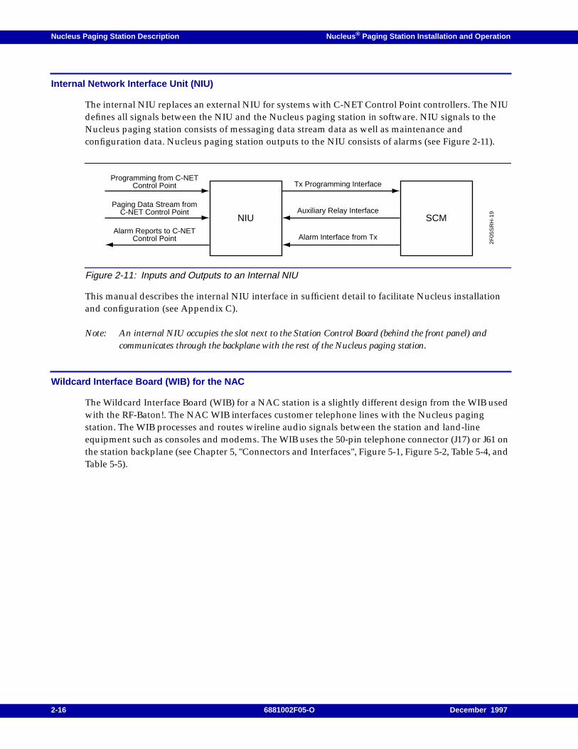
Nucleus Paging Station Description Nucleus ® Paging Station Installation and Operation
Internal Network Interface Unit (NIU)
The internal NIU replaces an external NIU for systems with C-NET Control Point controllers. The NIUdefines all signals between the NIU and the Nucleus paging station in software. NIU signals to theNucleus paging station consists of messaging data stream data as well as maintenance andconfiguration data. Nucleus paging station outputs to the NIU consists of alarms (see Figure 2-11).
Figure 2-11: Inputs and Outputs to an Internal NIU
This manual describes the internal NIU interface in sufficient detail to facilitate Nucleus installationand configuration (see Appendix C).
Note: An internal NIU occupies the slot next to the Station Control Board (behind the front panel) andcommunicates through the backplane with the rest of the Nucleus paging station.
Wildcard Interface Board (WIB) for the NAC
The Wildcard Interface Board (WIB) for a NAC station is a slightly different design from the WIB usedwith the RF-Baton!. The NAC WIB interfaces customer telephone lines with the Nucleus pagingstation. The WIB processes and routes wireline audio signals between the station and land-lineequipment such as consoles and modems. The WIB uses the 50-pin telephone connector (J17) or J61 onthe station backplane (see Chapter 5, "Connectors and Interfaces", Figure 5-1, Figure 5-2, Table 5-4, andTable 5-5).
NIU SCM
2F05
SR
H-1
9
Tx Programming Interface
Auxiliary Relay Interface
Alarm Interface from Tx
Programming from C-NETControl Point
Paging Data Stream fromC-NET Control Point
Alarm Reports to C-NETControl Point
2-16 6881002F05-O December 1997

Nucleus ® Paging Station Installation and Operation / Chapter 3
Installation Overview 3
This chapter describes overall site and clearance considerations when you install a Nucleus pagingstation or NAC station. This chapter contains the following information:
Purpose, 3-2Procedure Overview, 3-2FCC Compliance, 3-3
Grounding, Protection, and Shielding, 3-4Site Grounding, 3-4Ground Lug, 3-4Electrostatic Grounding, 3-4RF Shielding, 3-5
Environmental Conditions at the Site, 3-6
Input Power Requirements, 3-7
Equipment Mounting Methods, 3-8
Physical Dimensions and Clearances, 3-9Nucleus Cage Without Cabinet, 3-925-in. Indoor Cabinet, 3-1246-in. Indoor Cabinet, 3-1370-in. Indoor Cabinet, 3-16
Recommended Tools and Equipment, 3-18
GPS Antenna Installation, 3-19Sky Visibility, 3-19Mounting, 3-19RF Connectors, 3-21Interconnecting Cable, 3-21Single Receiver per Antenna, 3-21Cabling System Loss, 3-21
December 1997 6881002F05-O 3-1
Installation Overview Nucleus ® Paging Station Installation and Operation
Purpose
Proper installation maximizes performance and reliability for Nucleus and NAC paging stations. Pre-installation planning is essential. Pre-installation planning includes the following considerations:
• FCC compliance
• Location in relation to input power
• Location in relation to antenna(s)
• Location in relation to telephone lines
• Grounding requirements
• Heat and humidity
• Availability of air conditioning
• Mounting method
• Availability of required tools and equipment
Note: Read this section completely before installing the equipment.
Procedure Overview
Installation includes the following steps:
• Plan the installation.
• Unpack and inspect the equipment.
• Perform mechanical installation at the site.
• Complete necessary electrical and cabling connections, including the following:
– Site grounding
– AC or DC input power cabling
– Coaxial cables to transmit and receive antennas
– Phone line connections
– Site lightning protection
• Perform a post-installation functional test to verify proper installation.
3-2 6881002F05-O December 1997
Nucleus ® Paging Station Installation and Operation Installation Overview
FCC Compliance
FCC requirements state the following:
• The grantee of a license must ensure that all equipment operated under that license conforms tothe specifications of the license.
• The RF power output of a radio transmitter must not exceed the level required for satisfactorytechnical operations considering the area to be covered and the local conditions.
• The frequency, deviation, and power of a radio transmitter must be maintained within specificlimits. Check these three parameters before placing the station in service.
Note: Equipment efficiency depends on proper installation and service. Motorola recommends that thisequipment be installed and serviced only by certified technicians.
December 1997 6881002F05-O 3-3
Installation Overview Nucleus ® Paging Station Installation and Operation
Grounding, Protection, and Shielding
The conditions that make a site desirable for two-way radio communications are the same that make asite an excellent target for lightning strikes. Proper lightning protection methods can preventequipment damage in all but the most severe strikes. Even then, equipment damage may be kept to aminimum. Lightning protection is intended to prevent the electrical energy from a strike from enteringthe equipment room, and then preventing damage to the equipment as a result of induced voltages onpower, signal, and control lines to the equipment.
Although a comprehensive coverage of site grounding techniques and lightning protection is notwithin the scope of this manual, several industry sources provide rules and guidelines on groundingand lightning protection at communication sites. Motorola recommends Quality Standards–FNEInstallation Manual R56 (Motorola part number 6881089E50). Order this manual from the MotorolaAmericas Parts Division (see the Foreword).
Site Grounding
Site grounding requires two types of ground connections:
• Electrical ground—This type of ground includes AC and DC electrical power ground, telephoneline grounding, and low-voltage currents for alarms or sensors located at the site.
• Lightning ground—This type of ground protects against lightning strikes.
Ground Lug
The paging station cage is equipped with a single ground lug located on the backplane. Use this lug toconnect the cage to the site ground point.
Electrostatic Grounding
All Nucleus and NAC paging stations have provisions for electrostatic grounding. The formed tube ateach side of the front of the card cage chassis is marked with the grounding symbol. When handlingany module or circuit board, be sure to wear an antistatic wrist strap and plug the clip into the groundjack (formed tube) on the card cage (see Figure 3-1).
CAUTION
Do not use the ground lug for grounding of telephone lines, antenna cables, DC power, ACpower or other earth ground applications. Ground all elements safely and adequatelyaccording to national, state, local, and industry standards.
3-4 6881002F05-O December 1997
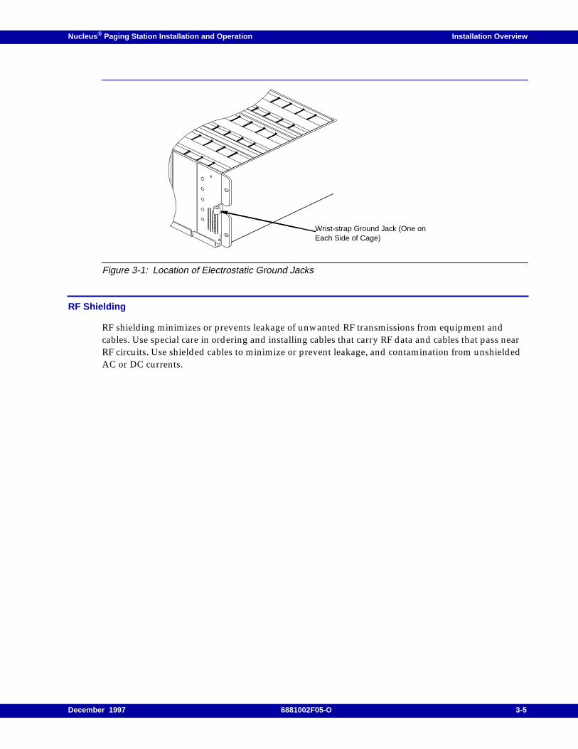
Nucleus ® Paging Station Installation and Operation Installation Overview
Figure 3-1: Location of Electrostatic Ground Jacks
RF Shielding
RF shielding minimizes or prevents leakage of unwanted RF transmissions from equipment andcables. Use special care in ordering and installing cables that carry RF data and cables that pass nearRF circuits. Use shielded cables to minimize or prevent leakage, and contamination from unshieldedAC or DC currents.
Wrist-strap Ground Jack (One onEach Side of Cage)
December 1997 6881002F05-O 3-5

Installation Overview Nucleus ® Paging Station Installation and Operation
Environmental Conditions at the Site
Install the Nucleus paging station in any location suitable for electronic communications equipment(environmental conditions do not exceed equipment requirements for temperature, humidity, and airquality) (see Table 3-1).
The PA module and power supply module have thermistor-controlled cooling fans to provide forcedconvection cooling. The air flow is front to back, allowing several cages to be stacked within a rack orcabinet. When planning the installation, observe the following ventilation guidelines:
• The operating range of the equipment is -30°C to +60°C/-22°F to +140°F.
• Customer-supplied cabinets must have adequate ventilation slots or openings in the front (for airentry) and back (for air to exit).
• All cabinets must have at least 6 inches of open space between the air vents and walls or othercabinets.
• Separate the cabinets to ensure that the air intake of one cabinet does not take in exhaust anadjacent cabinet.
• Motorola recommends an air conditioning system where the climate or the proximity of otherequipment threatens the temperature maximum.
CAUTION
To install the station in an environment that does not meet air quality requirements, cool andfilter the air for station modules must to meet air quality standards. Dust or dirt thataccumulate on the internal circuit boards and modules is difficult to remove. Dust and dirtcause malfunctions, such a as overheating and intermittent electrical failures.
Table 3-1: Required Environmental Conditions at the Site
Environmental Condition Requirement
Operating temperature -30o to +60oC (-22o to +140oF)
Humidity Not to exceed 95% relative humidity at 50˚C
Air quality
If the area is environmentally controlled:Airborne particulates level must not exceed 25 mg/m3If the area is not environmentally controlled:Airborne particulates level must not exceed 90 mg/m3
CAUTION
Failure to ensure proper ventilation and cooling voids the product warranty for a Nucleus orNAC paging station if it fails because of overheating.
3-6 6881002F05-O December 1997

Nucleus ® Paging Station Installation and Operation Installation Overview
Input Power Requirements
Nucleus and NAC paging stations have one or two AC power supplies (90 to 280 V rms, 50 Hz or60 Hz) or a DC-to-DC power supply (21 to 34.5 Vdc or 41 to 72 Vdc). All AC power supplies haveautomatic range and line frequency selection.
Motorola recommends a standard 3-wire grounded electrical outlet as the AC source. For a 125 Wstation and a nominal 110 Vac input, the AC source must supply 5 A. The AC source should beprotected by a circuit breaker rated at 15 A. For a nominal 220 Vac input, the AC source must supplyapproximately 2.5 A.
The high power (250 and 300 W) stations use two power supplies. These power supplies draw a totalof 13 A at 110 Vac, 60 Hz. They require a circuit breaker rated at 20 A.
For a 24 Vdc or 48/60 Vdc source, Motorola provides appropriate cabling from the DC power sourceto the backplane (located at rear of the station).
December 1997 6881002F05-O 3-7
Installation Overview Nucleus ® Paging Station Installation and Operation
Equipment Mounting Methods
Motorola supplies four mounting options for Nucleus and NAC paging stations:
• Installed in 25-in. cabinet (option X92)–this is a formed cabinet with front and rear vented doors.
• Installed in 46-in. cabinet (option X308)–this is a formed cabinet with front and rear vented doors.
• Installed in 70-in. cabinet (option C307)–this is a formed cabinet with front and rear vented doors.
• Shipped without rack or cabinet (option X362)–the customer can install the station in a rack orcabinet. The station is designed to fit standard EIA 19-in. rack configuration. For rack mounting,order option X153 mounting brackets.
3-8 6881002F05-O December 1997

Nucleus ® Paging Station Installation and Operation Installation Overview
Physical Dimensions and Clearances
This section presents the physical dimensions and clearance requirements for Nucleus equipmentinstalled in Nucleus cabinets or in cabinets with other equipment.
Nucleus Cage Without Cabinet
The dimensions and recommended clearances for a standard power or high-power station mountedwithout a cabinet appear in the figures listed below. The dimensions for standard and high powermodels are identical except for overall height.
• Side views of the standard power station and high power station (see Figure 3-2)
• Front view (see Figure 3-3)
• Clearance (see Figure 3-4)
December 1997 6881002F05-O 3-9
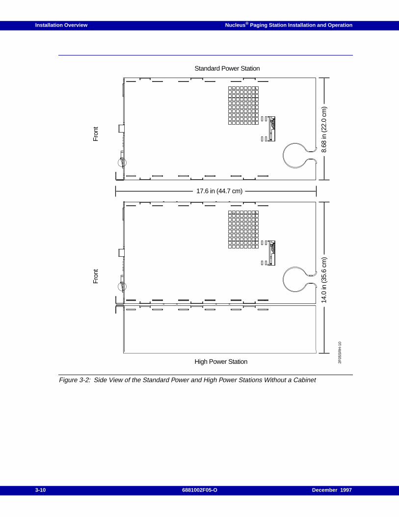
Installation Overview Nucleus ® Paging Station Installation and Operation
Figure 3-2: Side View of the Standard Power and High Power Stations Without a Cabinet
Fro
ntF
ront
8.68
in (2
2.0
cm)
14.0
in (3
5.6
cm)
Standard Power Station
High Power Station
17.6 in (44.7 cm)
2F05
SR
H-1
0
3-10 6881002F05-O December 1997
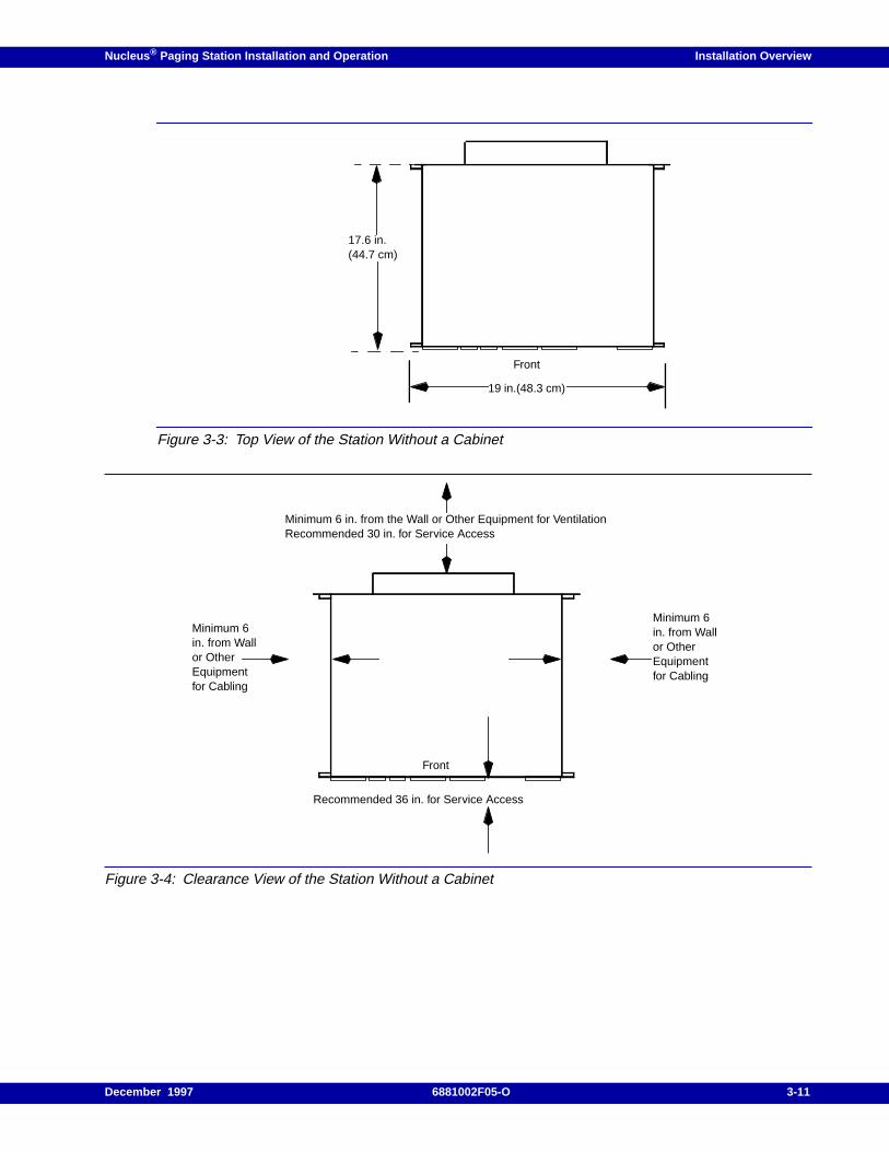
Nucleus ® Paging Station Installation and Operation Installation Overview
Figure 3-3: Top View of the Station Without a Cabinet
Figure 3-4: Clearance View of the Station Without a Cabinet
19 in.(48.3 cm)
Front
17.6 in.(44.7 cm)
Minimum 6 in. from the Wall or Other Equipment for VentilationRecommended 30 in. for Service Access
Front
Recommended 36 in. for Service Access
Minimum 6in. from Wallor OtherEquipmentfor Cabling
Minimum 6in. from Wallor OtherEquipmentfor Cabling
December 1997 6881002F05-O 3-11
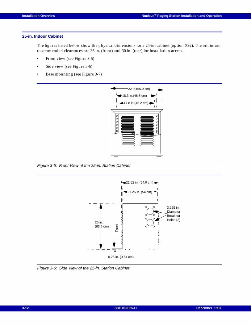
Installation Overview Nucleus ® Paging Station Installation and Operation
25-in. Indoor Cabinet
The figures listed below show the physical dimensions for a 25-in. cabinet (option X92). The minimumrecommended clearances are 36 in. (front) and 30 in. (rear) for installation access.
• Front view (see Figure 3-5)
• Side view (see Figure 3-6)
• Base mounting (see Figure 3-7)
Figure 3-5: Front View of the 25-in. Station Cabinet
Figure 3-6: Side View of the 25-in. Station Cabinet
22 in.(55.9 cm)
18.3 in.(46.5 cm)
17.8 in.(45.2 cm)
21.62 in. (54.9 cm)
Fron
t25 in.(63.5 cm)
0.25 in. (0.64 cm)
21.25 in. (54 cm)
3.625 in.DiameterBreakoutHoles (2)
3-12 6881002F05-O December 1997
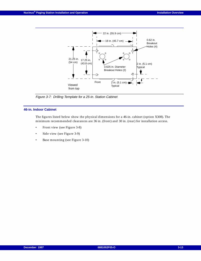
Nucleus ® Paging Station Installation and Operation Installation Overview
Figure 3-7: Drilling Template for a 25-in. Station Cabinet
46-in. Indoor Cabinet
The figures listed below show the physical dimensions for a 46-in. cabinet (option X308). Theminimum recommended clearances are 36 in. (front) and 30 in. (rear) for installation access.
• Front view (see Figure 3-8)
• Side view (see Figure 3-9)
• Base mounting (see Figure 3-10)
Viewedfrom top
21.25 in.(54 cm)
22 in. (55.9 cm)
0.62 in.BreakoutHoles (4)
2 in. (5.1 cm)Typical
2 in. (5.1 cm)Typical3.625 in. Diameter
Breakout Holes (2)
Front
17.25 in.(43.8 cm)
18 in. (45.7 cm)
December 1997 6881002F05-O 3-13
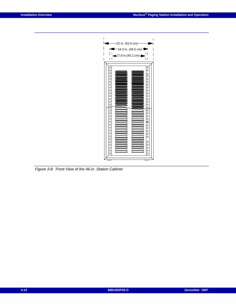
Installation Overview Nucleus ® Paging Station Installation and Operation
Figure 3-8: Front View of the 46-in. Station Cabinet
22 in. (55.9 cm)
18.3 in. (46.5 cm)
17.8 in.(45.2 cm)
3-14 6881002F05-O December 1997
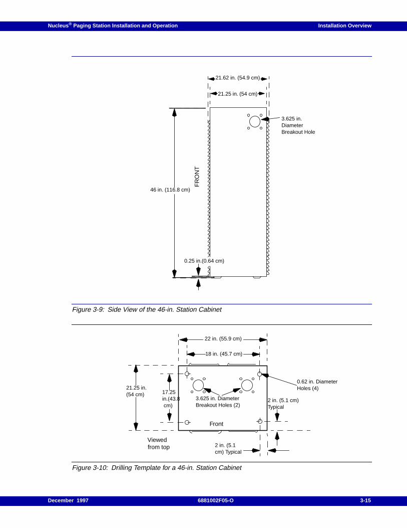
Nucleus ® Paging Station Installation and Operation Installation Overview
Figure 3-9: Side View of the 46-in. Station Cabinet
Figure 3-10: Drilling Template for a 46-in. Station Cabinet
21.62 in. (54.9 cm)
21.25 in. (54 cm)
FR
ON
T46 in. (116.8 cm)
3.625 in.DiameterBreakout Hole
0.25 in.(0.64 cm)
Viewedfrom top
21.25 in.(54 cm)
22 in. (55.9 cm)
0.62 in. DiameterHoles (4)
2 in. (5.1cm) Typical
2 in. (5.1 cm)Typical
3.625 in. DiameterBreakout Holes (2)
Front
17.25in.(43.8 cm)
18 in. (45.7 cm)
December 1997 6881002F05-O 3-15
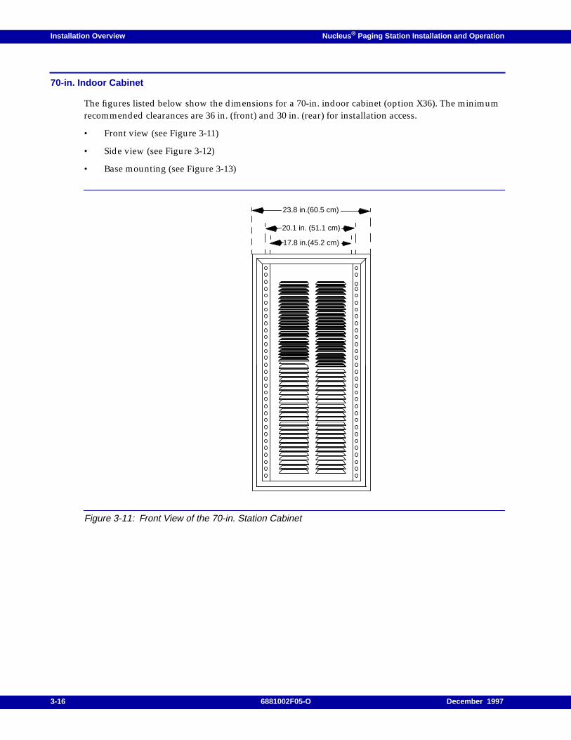
Installation Overview Nucleus ® Paging Station Installation and Operation
70-in. Indoor Cabinet
The figures listed below show the dimensions for a 70-in. indoor cabinet (option X36). The minimumrecommended clearances are 36 in. (front) and 30 in. (rear) for installation access.
• Front view (see Figure 3-11)
• Side view (see Figure 3-12)
• Base mounting (see Figure 3-13)
Figure 3-11: Front View of the 70-in. Station Cabinet
23.8 in.(60.5 cm)
20.1 in. (51.1 cm)
17.8 in.(45.2 cm)
3-16 6881002F05-O December 1997
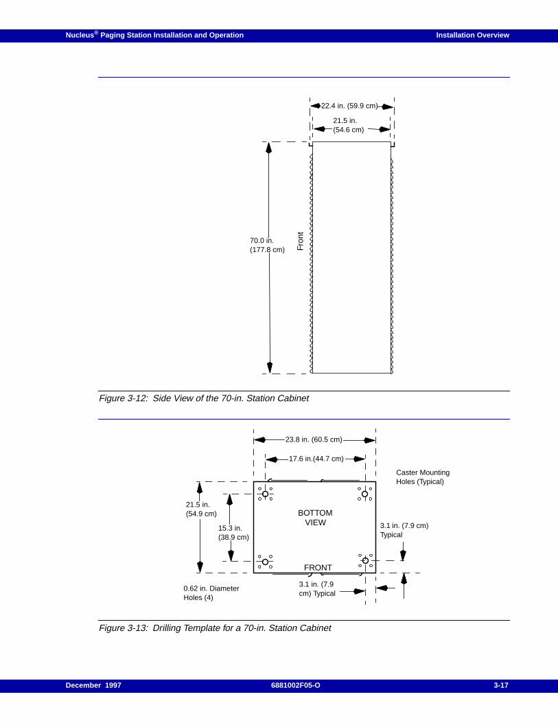
Nucleus ® Paging Station Installation and Operation Installation Overview
Figure 3-12: Side View of the 70-in. Station Cabinet
Figure 3-13: Drilling Template for a 70-in. Station Cabinet
22.4 in. (59.9 cm)
21.5 in.(54.6 cm)
Fron
t
70.0 in.(177.8 cm)
VIEW
21.5 in.(54.9 cm)
23.8 in. (60.5 cm)
0.62 in. DiameterHoles (4)
3.1 in. (7.9cm) Typical
3.1 in. (7.9 cm)Typical
FRONT
17.6 in.(44.7 cm)
Caster MountingHoles (Typical)
15.3 in.(38.9 cm)
BOTTOM
December 1997 6881002F05-O 3-17
Installation Overview Nucleus ® Paging Station Installation and Operation
Recommended Tools and Equipment
Installation requires the following tools and equipment:
• Standard electrician’s tool box (should contain a variety of hand tools appropriate for workingwith electrical circuits and associated equipment), including the following:
– TORX screwdriver, with TX15 and TX30 bits
– Small adjustable wrench or gas pliers
– Wire cutters (for cutting tie-wraps)
• Fiberglass or wooden stepladder, six to eight feet (used to access the top of the 70-in. cabinet).
• Block-and-tackle or suitable hoist to lift cabinets equipped with multiple stations
Note: Each fully equipped standard power station weighs approximately 60 lb. Each fully equipped highpower station weighs 105 lb.
• Power drill and appropriate boring bits for drilling concrete (for drilling anchor holes in concreteflooring)
• Tarpaulin or large plastic drop cloth to cover surrounding equipment while drilling concreteanchor holes (for installations where cabinet or rack is being anchored to concrete flooring)
• Vacuum cleaner for removing concrete dust (for installations where cabinet or rack is beinganchored to concrete flooring)
• ESD grounding strap
Motorola supplies the following materials with each station:
• Black M6 thread-cutting screws, part no. 0383498N08 (quantity 8)
• Power supply power cables (AC and DC)
DANGER
Use a fiberglass or wooden stepladder. Do not use a metal stepladder.Accidental contact with electrical wires could cause electrocution or seriousinjury.
3-18 6881002F05-O December 1997
Nucleus ® Paging Station Installation and Operation Installation Overview
GPS Antenna Installation
GPS synchronization requires attention to the following items:
• Sky visibility
• Mounting
• RF connectors
• Interconnecting cable
• Multiple receivers per antenna
• Cabling system loss
Sky Visibility
GPS requires sky visibility in an arc from directly overhead to within 10o of the horizon for optimumperformance. Obstructions such as adjacent buildings or towers may not block more than 20% of thecircumference of the sky visibility ring from 10o to 30o above the horizon. Consult Motorola for siteplanning advice.
Mounting
The disc-shaped GPS antenna should be mounted in the horizontal position (see Figure 3-14). Thepost-mounted L-shaped mounting bracket accepts a maximum diameter 30-mm post or bar.
DANGER
Do not mount the GPS antenna on a tower (lightning strikes to the tower damage the GPS
antenna or GPS receiver).
December 1997 6881002F05-O 3-19
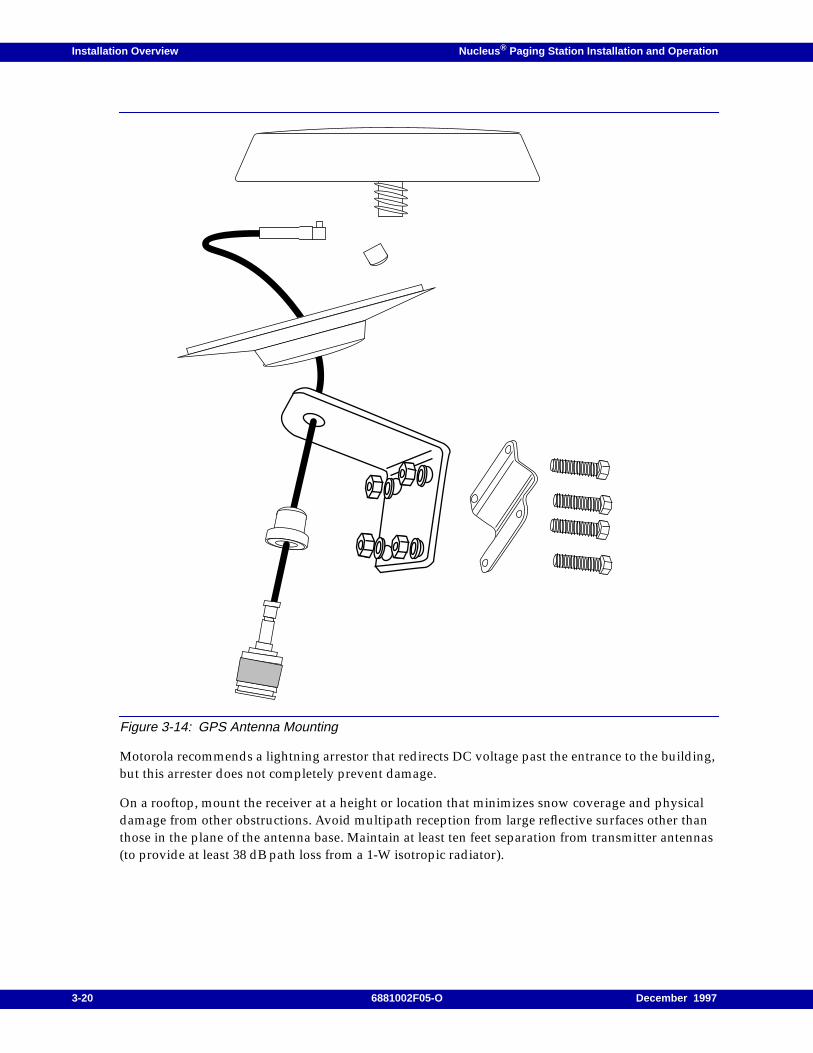
Installation Overview Nucleus ® Paging Station Installation and Operation
Figure 3-14: GPS Antenna Mounting
Motorola recommends a lightning arrestor that redirects DC voltage past the entrance to the building,but this arrester does not completely prevent damage.
On a rooftop, mount the receiver at a height or location that minimizes snow coverage and physicaldamage from other obstructions. Avoid multipath reception from large reflective surfaces other thanthose in the plane of the antenna base. Maintain at least ten feet separation from transmitter antennas(to provide at least 38 dB path loss from a 1-W isotropic radiator).
3-20 6881002F05-O December 1997
Nucleus ® Paging Station Installation and Operation Installation Overview
RF Connectors
The GPS connector is a N-type male (requires N-type female mating connector). The station connectoris an N-type female and requires N-type male mating connector. The connector center contacts aregold-plated. Weatherproof the connector at the GPS antenna; Motorola recommends part numberTDN9289A or its equivalent.
Interconnecting Cable
Motorola recommends a 50-Ohm low-loss outdoor coaxial cable with a solid copper outer conductorto minimize interference. The cable loss at 1.57542 GHz must be no more than 6 dB of gain.
An in-line amplifier may be used if it passes 5 V and uses no more than 25 mA at 5 V. Do not providemore than 6 dB of gain (including cable losses). The cabling system noise figure must be less than15 dB. The system noise figure must not exceed 4 dB. Motorola provides site engineering or systeminstallation to assist in achieving these requirements.
Single Receiver per Antenna
The GPS receiver provides 5 V to the active GPS antenna. The output is not reverse-polarity protected;multiple receivers cannot be connected directly from one antenna. Only one GPS receiver may powerthe GPS antenna; all other ports to other receivers must be DC-blocked to prevent damage.
Cabling System Loss
The maximum allowed voltage drop for the antenna is 0.25 V at 22 mA plus in-line amplifier currentdrain. This maximum voltage drop includes losses of the in-line amplifier(s) and bias tees; antenna-loss only is 11-Ohm maximum. Test delivered voltage by placing a 200-Ohm source at the antennaconnection point. The minimum voltage delivered should be 4.5 V. The required supply input voltageto the GPS antenna is 5.5 V to 4.5 V.
December 1997 6881002F05-O 3-21

Installation Overview Nucleus ® Paging Station Installation and Operation
3-22 6881002F05-O December 1997

Nucleus ® Paging Station Installation and Operation / Chapter 4
Mechanical Installation 4
This chapter describes the procedures necessary to unpack and mechanically install a Nucleus pagingstation or a Nucleus paging station with Advanced Control (NAC). This chapter contains thefollowing information:
Equipment Unpacking and Inspection, 4-2Unpacking Nucleus Paging Stations Without Cabinets, 4-2Unpacking 25-in., 46-in., and 70-in. Indoor Cabinets, 4-3
Installing 25-in., 46-in., and 70-in. Cabinets, 4-6
Mounting Procedures, 4-8Mounting all Nucleus Paging Station Cages in EIA Cabinets, 4-8Mounting the Standard Power Nucleus Paging Station, 4-8Mounting the High Power Nucleus Paging Station, 4-13Stacking Cabinets, 4-19
December 1997 6881002F05-O 4-1
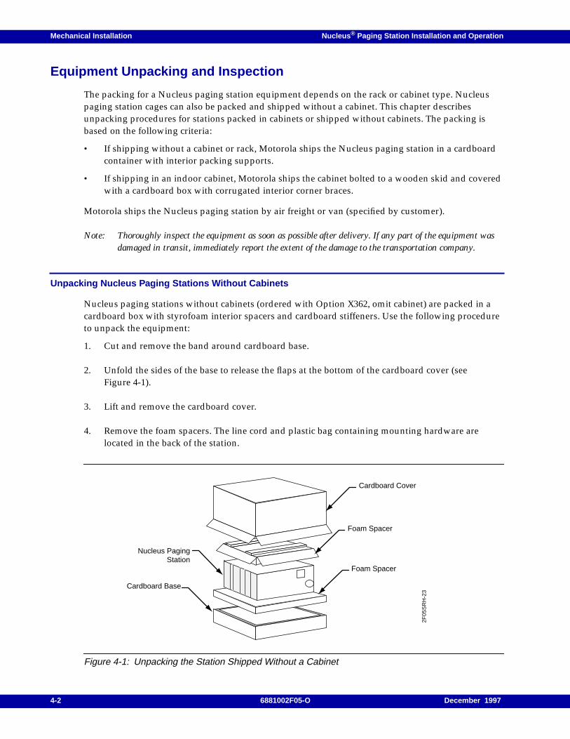
Mechanical Installation Nucleus ® Paging Station Installation and Operation
Equipment Unpacking and Inspection
The packing for a Nucleus paging station equipment depends on the rack or cabinet type. Nucleuspaging station cages can also be packed and shipped without a cabinet. This chapter describesunpacking procedures for stations packed in cabinets or shipped without cabinets. The packing isbased on the following criteria:
• If shipping without a cabinet or rack, Motorola ships the Nucleus paging station in a cardboardcontainer with interior packing supports.
• If shipping in an indoor cabinet, Motorola ships the cabinet bolted to a wooden skid and coveredwith a cardboard box with corrugated interior corner braces.
Motorola ships the Nucleus paging station by air freight or van (specified by customer).
Note: Thoroughly inspect the equipment as soon as possible after delivery. If any part of the equipment wasdamaged in transit, immediately report the extent of the damage to the transportation company.
Unpacking Nucleus Paging Stations Without Cabinets
Nucleus paging stations without cabinets (ordered with Option X362, omit cabinet) are packed in acardboard box with styrofoam interior spacers and cardboard stiffeners. Use the following procedureto unpack the equipment:
1. Cut and remove the band around cardboard base.
2. Unfold the sides of the base to release the flaps at the bottom of the cardboard cover (seeFigure 4-1).
3. Lift and remove the cardboard cover.
4. Remove the foam spacers. The line cord and plastic bag containing mounting hardware arelocated in the back of the station.
Figure 4-1: Unpacking the Station Shipped Without a Cabinet
Cardboard Cover
Foam Spacer
Foam Spacer
Nucleus PagingStation
Cardboard Base
2F05
SR
H-2
3
4-2 6881002F05-O December 1997
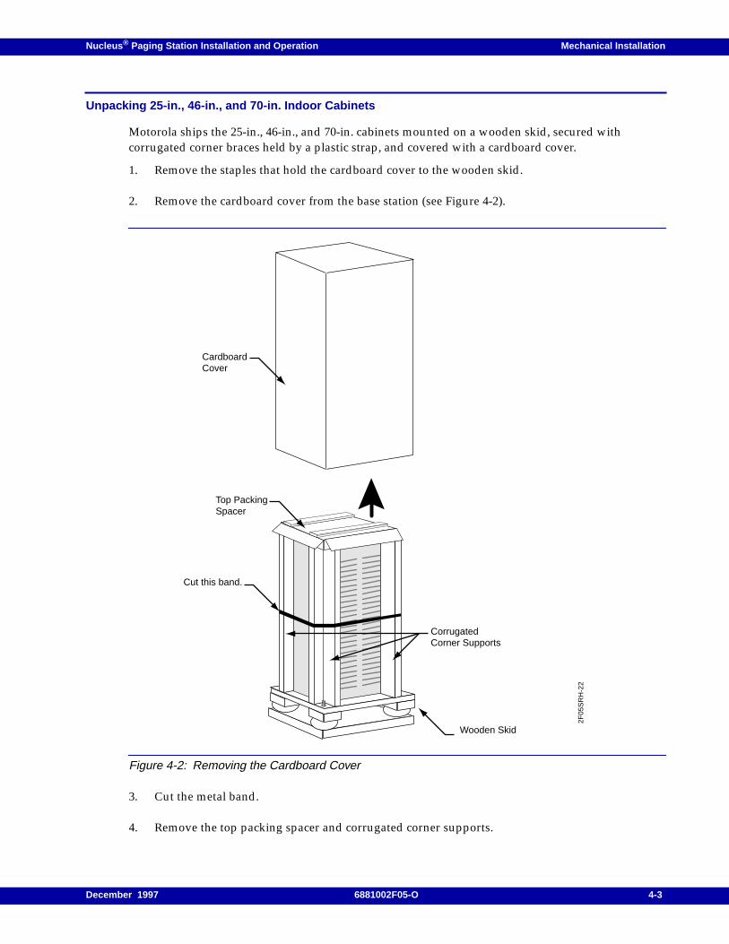
Nucleus ® Paging Station Installation and Operation Mechanical Installation
Unpacking 25-in., 46-in., and 70-in. Indoor Cabinets
Motorola ships the 25-in., 46-in., and 70-in. cabinets mounted on a wooden skid, secured withcorrugated corner braces held by a plastic strap, and covered with a cardboard cover.
1. Remove the staples that hold the cardboard cover to the wooden skid.
2. Remove the cardboard cover from the base station (see Figure 4-2).
Figure 4-2: Removing the Cardboard Cover
3. Cut the metal band.
4. Remove the top packing spacer and corrugated corner supports.
Top PackingSpacer
Cut this band.
CorrugatedCorner Supports
Wooden Skid
CardboardCover
2F05
SR
H-2
2
December 1997 6881002F05-O 4-3
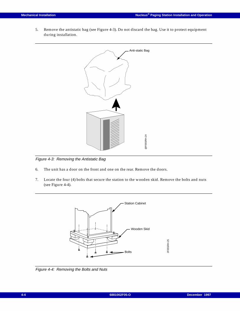
Mechanical Installation Nucleus ® Paging Station Installation and Operation
5. Remove the antistatic bag (see Figure 4-3). Do not discard the bag. Use it to protect equipmentduring installation.
Figure 4-3: Removing the Antistatic Bag
6. The unit has a door on the front and one on the rear. Remove the doors.
7. Locate the four (4) bolts that secure the station to the wooden skid. Remove the bolts and nuts(see Figure 4-4).
Figure 4-4: Removing the Bolts and Nuts
Anti-static Bag
@F
05S
RH
-24
Station Cabinet
Wooden Skid
Bolts 2F05
SR
H-2
5
4-4 6881002F05-O December 1997

Nucleus ® Paging Station Installation and Operation Mechanical Installation
8. The station cabinet has lifting rings on the top front and top back. Attach these lift rings to a hoistto lift raise the station from the skid.
9. Remove the skid and return the station to the floor.
10. Replace the antistatic bag over the unit to protect it during installation.
December 1997 6881002F05-O 4-5
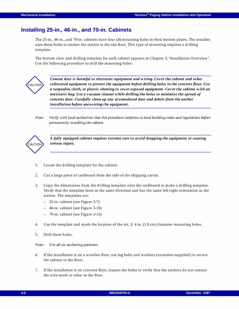
Mechanical Installation Nucleus ® Paging Station Installation and Operation
Installing 25-in., 46-in., and 70-in. Cabinets
The 25-in., 46-in., and 70-in. cabinets have four (4) mounting holes in their bottom plates. The installeruses these holes to anchor the station to the site floor. This type of mounting requires a drillingtemplate.
The bottom view and drilling template for each cabinet appears in Chapter 3, "Installation Overview".Use the following procedure to drill the mounting holes:
Note: Verify with local authorities that this procedure conforms to local building codes and regulations beforepermanently installing the cabinet.
1. Locate the drilling template for the cabinet.
2. Cut a large piece of cardboard from the side of the shipping carton.
3. Copy the dimensions from the drilling template onto the cardboard to make a drilling template.Verify that the template faces in the same direction and has the same left-right orientation as thestation. The templates are:
– 25-in. cabinet (see Figure 3-7)
– 46-in. cabinet (see Figure 3-10)
– 70-in. cabinet (see Figure 3-13)
4. Use the template and mark the location of the six, 3/4 in. (1.9 cm) diameter mounting holes.
5. Drill these holes.
Note: Use all six anchoring positions.
6. If the installation is on a wooden floor, use lag bolts and washers (customer-supplied) to securethe cabinet to the floor.
7. If the installation is on concrete floor, inspect the holes to verify that the anchors do not contactthe wire mesh or rebar in the floor.
CAUTION
Cement dust is harmful to electronic equipment and wiring. Cover the cabinet and othercollocated equipment to protect the equipment before drilling holes in the concrete floor. Usea tarpaulin, cloth, or plastic sheeting to cover exposed equipment. Cover the cabinet with anantistatic bag. Use a vacuum cleaner while drilling the holes to minimize the spread ofconcrete dust. Carefully clean up any accumulated dust and debris from the anchorinstallation before uncovering the equipment.
CAUTION
A fully equipped cabinet requires extreme care to avoid dropping the equipment or causingserious injury.
4-6 6881002F05-O December 1997
Nucleus ® Paging Station Installation and Operation Mechanical Installation
8. Install the mounting anchors (RAM RD-56 anchors recommended) using the instructionsprovided with the anchors.
9. Align the cabinet with the installed anchors.
10. Lower the cabinet to the floor and lightly secure the cabinet with the proper mounting hardware.
Note: Do not tighten the mounting hardware at this time.
11. Verify that the cabinet is plumb in the vertical direction. Verify that the top of the cabinet is level.Use shims (flat washers or flat aluminum plates) under the cabinet mounting foot to achievevertical plumb and horizontal level.
12. Tightly secure the cabinet to the floor anchors, while maintaining vertical plumb and horizontallevel.
13. Remove all debris and vacuum all dust. Remove protective coverings from the equipment andthe antistatic bag from the cabinet.
CAUTION
Isolate the cabinet electrically from any other equipment or materials at the site.
December 1997 6881002F05-O 4-7
Mechanical Installation Nucleus ® Paging Station Installation and Operation
Mounting Procedures
This procedure applies to mechanical installation in standard Electrical Industries Association (EIA)cabinets. The standard power and high power stations have different mounting procedures. Refer tothe mounting procedures for your type of station.
Mounting all Stations in EIA Cabinets
Note: Do not begin this procedure until the EIA cabinet is securely fastened to the floor at its base.
Stations in EIA racks require stand-off brackets to center the cage within the rack mounting rails. Orderoption X153, which includes mounting brackets and slotted screws.
Motorola provides mounting screws (M6x1.0 tapping) with each station to secure the cage flanges tothe stand-off brackets. Installing multiple cages one above the other is permitted as long as properventilation is maintained (see Chapter 3, "Installation Overview").
Mounting the Standard Power Station
This procedure describes installation of a standard power station in a standard EIA 19-in. cabinet.
Note: Perform the procedures in sequence.
1. Remove the station from the packing kit. If the station is too heavy to lift from the packing carton,lighten the station by removing the power supply and power amplifier (PA) from the front of thestation as follows:
a. Remove the two TORX screws holding the power supply using a TORX screwdriver andTX15 bit. Remove the power supply and set it aside in a safe location.
b. Remove the two TORX screws holding the PA in the cage. Remove the PA from the cage andset it aside in a safe location.
CAUTION
In a multiple-unit rack install equipment at the lowest possible position in the rack.Continue installing equipment, building toward the top of the rack. This procedure ensuresthat the rack is not top-heavy.
CAUTION
Each standard power station weights approximately 60 lb. The unit requires two people tolift and handle it.
4-8 6881002F05-O December 1997
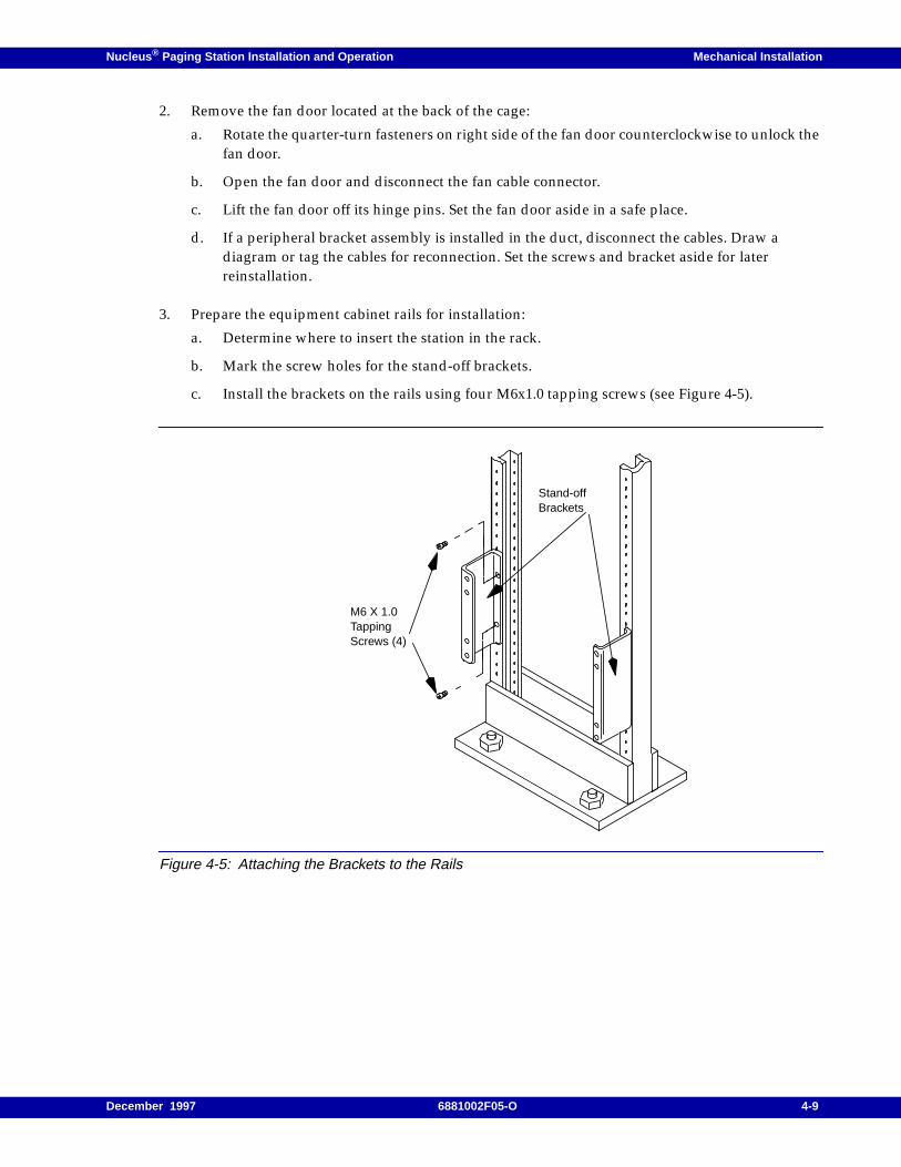
Nucleus ® Paging Station Installation and Operation Mechanical Installation
2. Remove the fan door located at the back of the cage:
a. Rotate the quarter-turn fasteners on right side of the fan door counterclockwise to unlock thefan door.
b. Open the fan door and disconnect the fan cable connector.
c. Lift the fan door off its hinge pins. Set the fan door aside in a safe place.
d. If a peripheral bracket assembly is installed in the duct, disconnect the cables. Draw adiagram or tag the cables for reconnection. Set the screws and bracket aside for laterreinstallation.
3. Prepare the equipment cabinet rails for installation:
a. Determine where to insert the station in the rack.
b. Mark the screw holes for the stand-off brackets.
c. Install the brackets on the rails using four M6x1.0 tapping screws (see Figure 4-5).
Figure 4-5: Attaching the Brackets to the Rails
Stand-offBrackets
M6 X 1.0TappingScrews (4)
December 1997 6881002F05-O 4-9
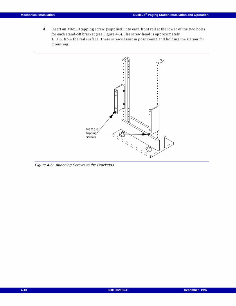
Mechanical Installation Nucleus ® Paging Station Installation and Operation
d. Insert an M6x1.0 tapping screw (supplied) into each front rail at the lower of the two holesfor each stand-off bracket (see Figure 4-6). The screw head is approximately1/8 in. from the rail surface. These screws assist in positioning and holding the station formounting.
Figure 4-6: Attaching Screws to the Brackets&
M6 X 1.0TappingScrews
4-10 6881002F05-O December 1997
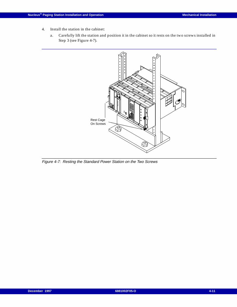
Nucleus ® Paging Station Installation and Operation Mechanical Installation
4. Install the station in the cabinet:
a. Carefully lift the station and position it in the cabinet so it rests on the two screws installed inStep 3 (see Figure 4-7).
Figure 4-7: Resting the Standard Power Station on the Two Screws
Rest CageOn Screws
December 1997 6881002F05-O 4-11
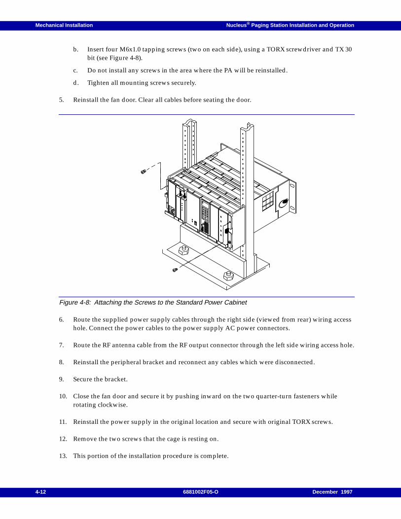
Mechanical Installation Nucleus ® Paging Station Installation and Operation
b. Insert four M6x1.0 tapping screws (two on each side), using a TORX screwdriver and TX 30bit (see Figure 4-8).
c. Do not install any screws in the area where the PA will be reinstalled.
d. Tighten all mounting screws securely.
5. Reinstall the fan door. Clear all cables before seating the door.
Figure 4-8: Attaching the Screws to the Standard Power Cabinet
6. Route the supplied power supply cables through the right side (viewed from rear) wiring accesshole. Connect the power cables to the power supply AC power connectors.
7. Route the RF antenna cable from the RF output connector through the left side wiring access hole.
8. Reinstall the peripheral bracket and reconnect any cables which were disconnected.
9. Secure the bracket.
10. Close the fan door and secure it by pushing inward on the two quarter-turn fasteners whilerotating clockwise.
11. Reinstall the power supply in the original location and secure with original TORX screws.
12. Remove the two screws that the cage is resting on.
13. This portion of the installation procedure is complete.
4-12 6881002F05-O December 1997
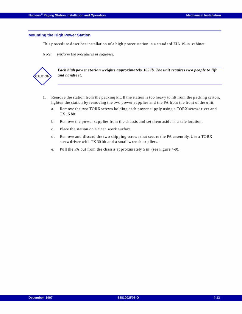
Nucleus ® Paging Station Installation and Operation Mechanical Installation
Mounting the High Power Station
This procedure describes installation of a high power station in a standard EIA 19-in. cabinet.
Note: Perform the procedures in sequence.
1. Remove the station from the packing kit. If the station is too heavy to lift from the packing carton,lighten the station by removing the two power supplies and the PA from the front of the unit:
a. Remove the two TORX screws holding each power supply using a TORX screwdriver andTX 15 bit.
b. Remove the power supplies from the chassis and set them aside in a safe location.
c. Place the station on a clean work surface.
d. Remove and discard the two shipping screws that secure the PA assembly. Use a TORXscrewdriver with TX 30 bit and a small wrench or pliers.
e. Pull the PA out from the chassis approximately 5 in. (see Figure 4-9).
CAUTION
Each high power station weights approximately 105 lb. The unit requires two people to liftand handle it.
December 1997 6881002F05-O 4-13
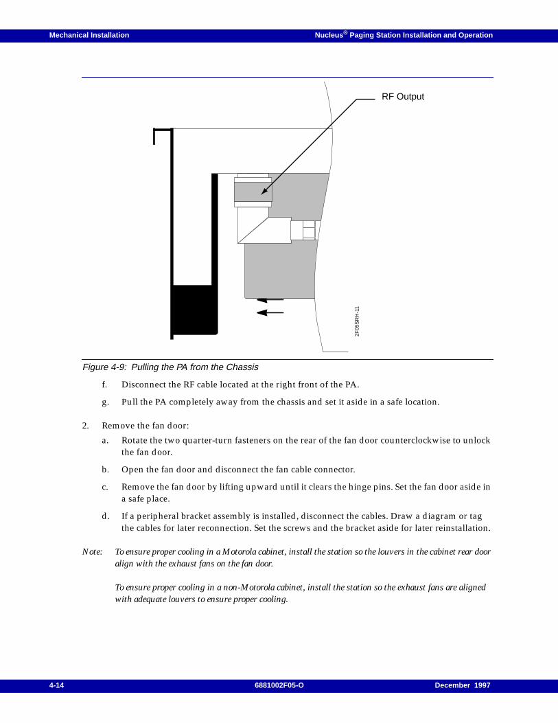
Mechanical Installation Nucleus ® Paging Station Installation and Operation
Figure 4-9: Pulling the PA from the Chassis
f. Disconnect the RF cable located at the right front of the PA.
g. Pull the PA completely away from the chassis and set it aside in a safe location.
2. Remove the fan door:
a. Rotate the two quarter-turn fasteners on the rear of the fan door counterclockwise to unlockthe fan door.
b. Open the fan door and disconnect the fan cable connector.
c. Remove the fan door by lifting upward until it clears the hinge pins. Set the fan door aside ina safe place.
d. If a peripheral bracket assembly is installed, disconnect the cables. Draw a diagram or tagthe cables for later reconnection. Set the screws and the bracket aside for later reinstallation.
Note: To ensure proper cooling in a Motorola cabinet, install the station so the louvers in the cabinet rear dooralign with the exhaust fans on the fan door.
To ensure proper cooling in a non-Motorola cabinet, install the station so the exhaust fans are alignedwith adequate louvers to ensure proper cooling.
2F05
SR
H-1
1
RF Output
4-14 6881002F05-O December 1997
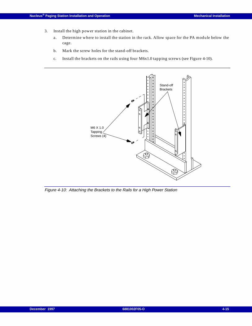
Nucleus ® Paging Station Installation and Operation Mechanical Installation
3. Install the high power station in the cabinet.
a. Determine where to install the station in the rack. Allow space for the PA module below thecage.
b. Mark the screw holes for the stand-off brackets.
c. Install the brackets on the rails using four M6x1.0 tapping screws (see Figure 4-10).
Figure 4-10: Attaching the Brackets to the Rails for a High Power Station
Stand-offBrackets
M6 X 1.0TappingScrews (4)
December 1997 6881002F05-O 4-15
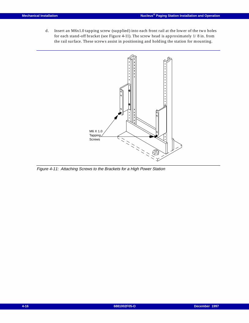
Mechanical Installation Nucleus ® Paging Station Installation and Operation
d. Insert an M6x1.0 tapping screw (supplied) into each front rail at the lower of the two holesfor each stand-off bracket (see Figure 4-11). The screw head is approximately 1/8 in. fromthe rail surface. These screws assist in positioning and holding the station for mounting.
Figure 4-11: Attaching Screws to the Brackets for a High Power Station
M6 X 1.0TappingScrews
4-16 6881002F05-O December 1997
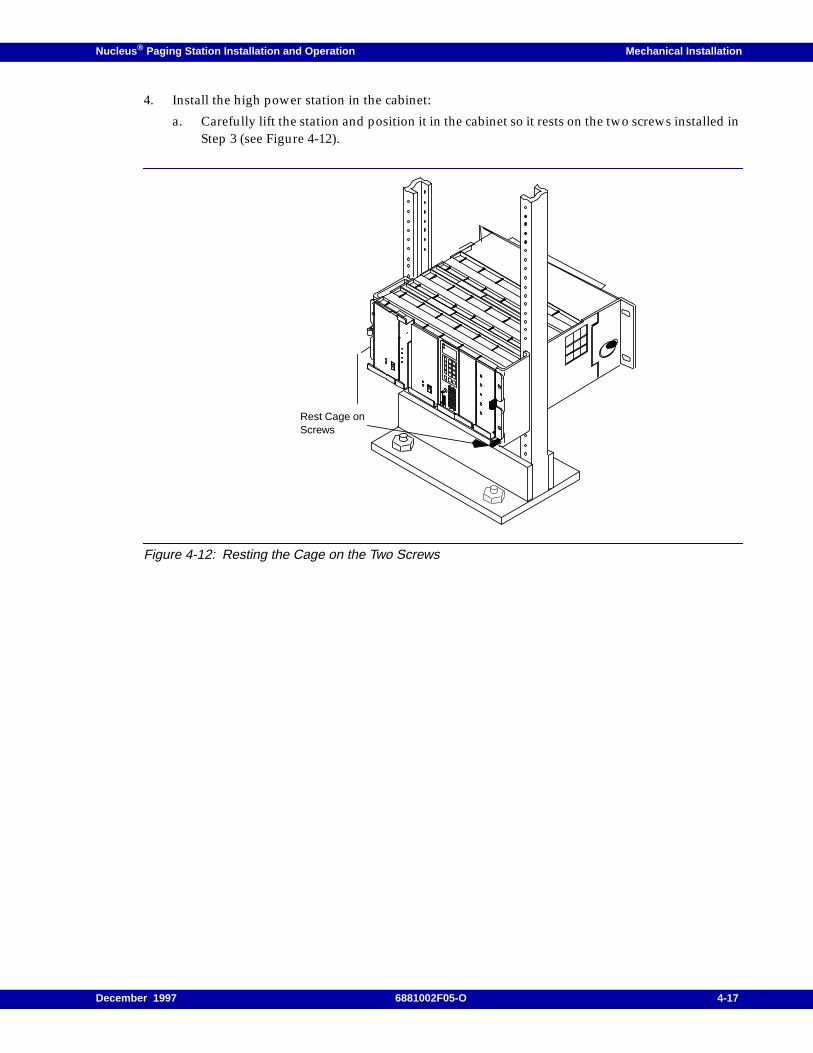
Nucleus ® Paging Station Installation and Operation Mechanical Installation
4. Install the high power station in the cabinet:
a. Carefully lift the station and position it in the cabinet so it rests on the two screws installed inStep 3 (see Figure 4-12).
Figure 4-12: Resting the Cage on the Two Screws
Rest Cage onScrews
December 1997 6881002F05-O 4-17
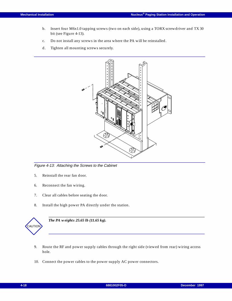
Mechanical Installation Nucleus ® Paging Station Installation and Operation
b. Insert four M6x1.0 tapping screws (two on each side), using a TORX screwdriver and TX 30bit (see Figure 4-13).
c. Do not install any screws in the area where the PA will be reinstalled.
d. Tighten all mounting screws securely.
Figure 4-13: Attaching the Screws to the Cabinet
5. Reinstall the rear fan door.
6. Reconnect the fan wiring.
7. Clear all cables before seating the door.
8. Install the high power PA directly under the station.
9. Route the RF and power supply cables through the right side (viewed from rear) wiring accesshole.
10. Connect the power cables to the power supply AC power connectors.
CAUTION
The PA weights 25.65 lb (11.65 kg).
4-18 6881002F05-O December 1997
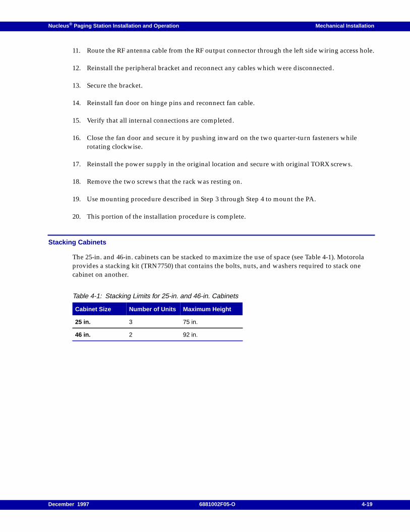
Nucleus ® Paging Station Installation and Operation Mechanical Installation
11. Route the RF antenna cable from the RF output connector through the left side wiring access hole.
12. Reinstall the peripheral bracket and reconnect any cables which were disconnected.
13. Secure the bracket.
14. Reinstall fan door on hinge pins and reconnect fan cable.
15. Verify that all internal connections are completed.
16. Close the fan door and secure it by pushing inward on the two quarter-turn fasteners whilerotating clockwise.
17. Reinstall the power supply in the original location and secure with original TORX screws.
18. Remove the two screws that the rack was resting on.
19. Use mounting procedure described in Step 3 through Step 4 to mount the PA.
20. This portion of the installation procedure is complete.
Stacking Cabinets
The 25-in. and 46-in. cabinets can be stacked to maximize the use of space (see Table 4-1). Motorolaprovides a stacking kit (TRN7750) that contains the bolts, nuts, and washers required to stack onecabinet on another.
Table 4-1: Stacking Limits for 25-in. and 46-in. Cabinets
Cabinet Size Number of Units Maximum Height
25 in. 3 75 in.
46 in. 2 92 in.
December 1997 6881002F05-O 4-19

Mechanical Installation Nucleus ® Paging Station Installation and Operation
4-20 6881002F05-O December 1997
Nucleus ® Paging Station Installation and Operation / Chapter 5
Connectors and Interfaces 5
The Nucleus paging station supports a variety of interfaces. Most interfaces connect through theNucleus paging station backplane. This chapter describes these interfaces. This chapter contains thefollowing information:
Backplane Interfaces, 5-2
Installing Communication Peripherals, 5-5
Installing Synchronization Peripherals, 5-10
Installing RF Interfaces and Antenna Options, 5-11Single Antenna Transmit and Receive (Antenna Relay Option X371), 5-11Separate Transmit and Receive Antenna, 5-12
Installing Power, 5-14Ground at the Ground Lug, 5-15DC Power to Fans and External Devices, 5-15AC Power, 5-16DC Power from a Power Supply, 5-17Standard Power Station Battery Revert, 5-21
Connecting the RF-B! Transmitter Controller, 5-24
NAC Wireline Configuration, 5-25
December 1997 6881002F05-O 5-1
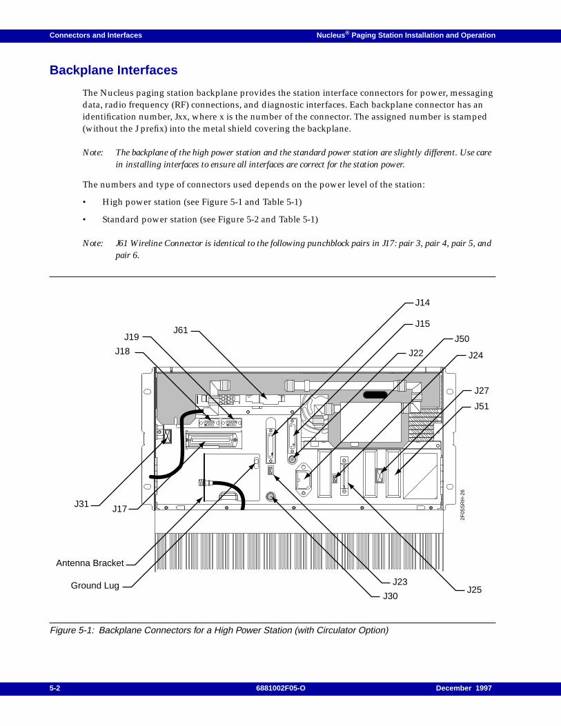
Connectors and Interfaces Nucleus ® Paging Station Installation and Operation
Backplane Interfaces
The Nucleus paging station backplane provides the station interface connectors for power, messagingdata, radio frequency (RF) connections, and diagnostic interfaces. Each backplane connector has anidentification number, Jxx, where x is the number of the connector. The assigned number is stamped(without the J prefix) into the metal shield covering the backplane.
Note: The backplane of the high power station and the standard power station are slightly different. Use carein installing interfaces to ensure all interfaces are correct for the station power.
The numbers and type of connectors used depends on the power level of the station:
• High power station (see Figure 5-1 and Table 5-1)
• Standard power station (see Figure 5-2 and Table 5-1)
Note: J61 Wireline Connector is identical to the following punchblock pairs in J17: pair 3, pair 4, pair 5, andpair 6.
Figure 5-1: Backplane Connectors for a High Power Station (with Circulator Option)
2F05
SR
H-2
6
J18
J19J61
J14
J15
J22
J50
J24
J27
J51
J23J25
J30Ground Lug
Antenna Bracket
J31 J17
5-2 6881002F05-O December 1997
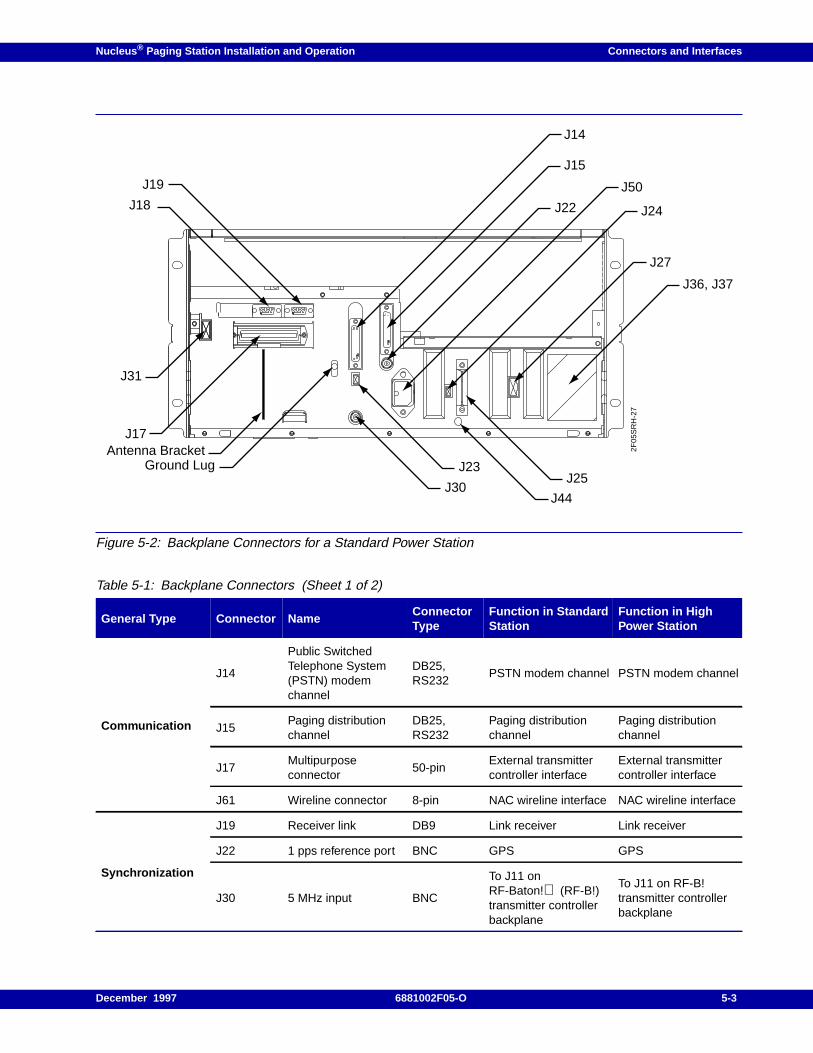
Nucleus ® Paging Station Installation and Operation Connectors and Interfaces
Figure 5-2: Backplane Connectors for a Standard Power Station
Table 5-1: Backplane Connectors (Sheet 1 of 2)
General Type Connector NameConnectorType
Function in StandardStation
Function in HighPower Station
Communication
J14
Public SwitchedTelephone System(PSTN) modemchannel
DB25,RS232
PSTN modem channel PSTN modem channel
J15Paging distributionchannel
DB25,RS232
Paging distributionchannel
Paging distributionchannel
J17Multipurposeconnector
50-pinExternal transmittercontroller interface
External transmittercontroller interface
J61 Wireline connector 8-pin NAC wireline interface NAC wireline interface
Synchronization
J19 Receiver link DB9 Link receiver Link receiver
J22 1 pps reference port BNC GPS GPS
J30 5 MHz input BNC
To J11 onRF-Baton! (RF-B!)transmitter controllerbackplane
To J11 on RF-B!transmitter controllerbackplane
2F05
SR
H-2
7
J18
J19
J14
J15
J22
J50
J24
J27
J36, J37
J23J25
J44J30
Ground Lug
J17
J31
Antenna Bracket
December 1997 6881002F05-O 5-3
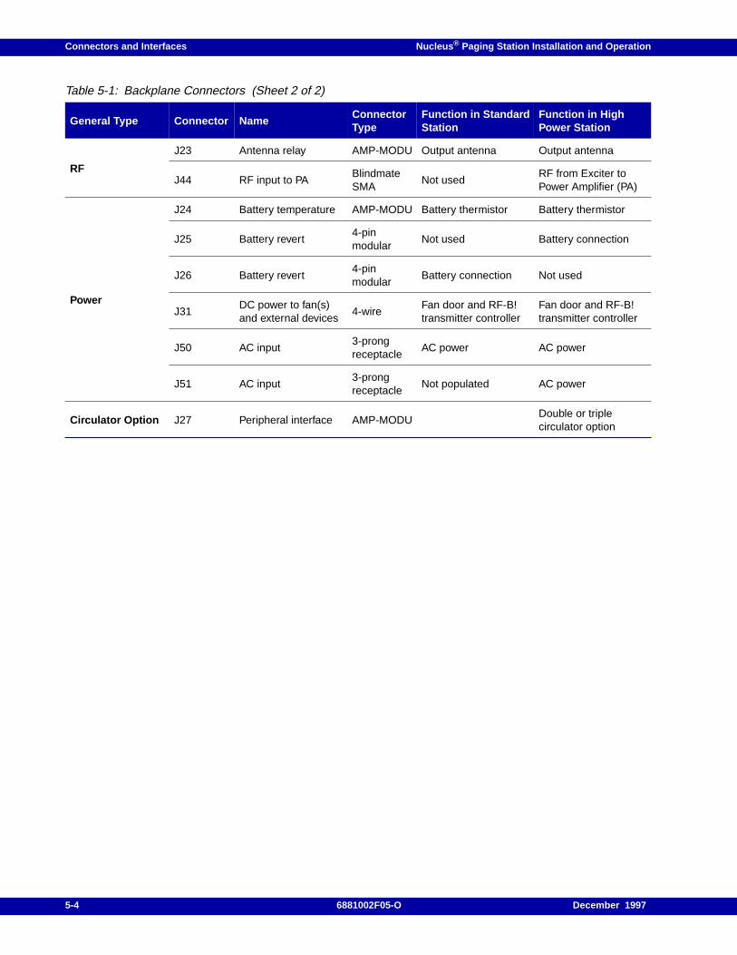
Connectors and Interfaces Nucleus ® Paging Station Installation and Operation
RF
J23 Antenna relay AMP-MODU Output antenna Output antenna
J44 RF input to PABlindmateSMA
Not usedRF from Exciter toPower Amplifier (PA)
Power
J24 Battery temperature AMP-MODU Battery thermistor Battery thermistor
J25 Battery revert4-pinmodular
Not used Battery connection
J26 Battery revert4-pinmodular
Battery connection Not used
J31DC power to fan(s)and external devices
4-wireFan door and RF-B!transmitter controller
Fan door and RF-B!transmitter controller
J50 AC input3-prongreceptacle
AC power AC power
J51 AC input3-prongreceptacle
Not populated AC power
Circulator Option J27 Peripheral interface AMP-MODUDouble or triplecirculator option
Table 5-1: Backplane Connectors (Sheet 2 of 2)
General Type Connector NameConnectorType
Function in StandardStation
Function in HighPower Station
5-4 6881002F05-O December 1997
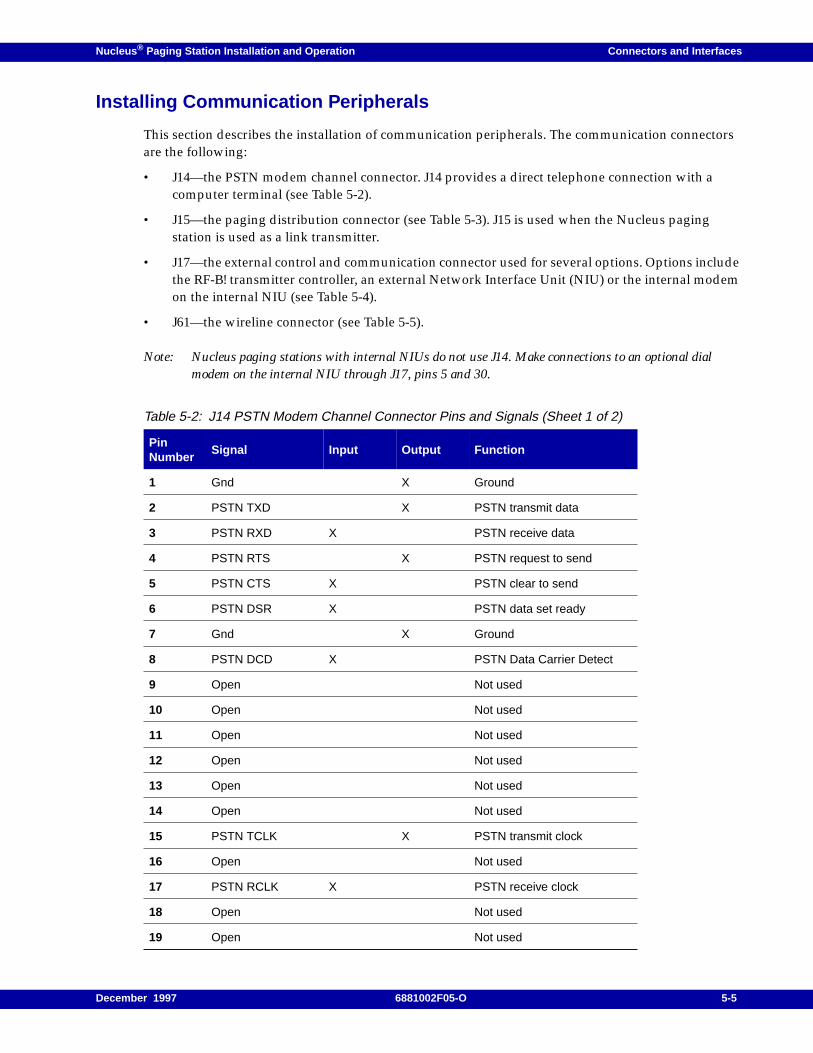
Nucleus ® Paging Station Installation and Operation Connectors and Interfaces
Installing Communication Peripherals
This section describes the installation of communication peripherals. The communication connectorsare the following:
• J14—the PSTN modem channel connector. J14 provides a direct telephone connection with acomputer terminal (see Table 5-2).
• J15—the paging distribution connector (see Table 5-3). J15 is used when the Nucleus pagingstation is used as a link transmitter.
• J17—the external control and communication connector used for several options. Options includethe RF-B! transmitter controller, an external Network Interface Unit (NIU) or the internal modemon the internal NIU (see Table 5-4).
• J61—the wireline connector (see Table 5-5).
Note: Nucleus paging stations with internal NIUs do not use J14. Make connections to an optional dialmodem on the internal NIU through J17, pins 5 and 30.
Table 5-2: J14 PSTN Modem Channel Connector Pins and Signals (Sheet 1 of 2)
PinNumber
Signal Input Output Function
1 Gnd X Ground
2 PSTN TXD X PSTN transmit data
3 PSTN RXD X PSTN receive data
4 PSTN RTS X PSTN request to send
5 PSTN CTS X PSTN clear to send
6 PSTN DSR X PSTN data set ready
7 Gnd X Ground
8 PSTN DCD X PSTN Data Carrier Detect
9 Open Not used
10 Open Not used
11 Open Not used
12 Open Not used
13 Open Not used
14 Open Not used
15 PSTN TCLK X PSTN transmit clock
16 Open Not used
17 PSTN RCLK X PSTN receive clock
18 Open Not used
19 Open Not used
December 1997 6881002F05-O 5-5
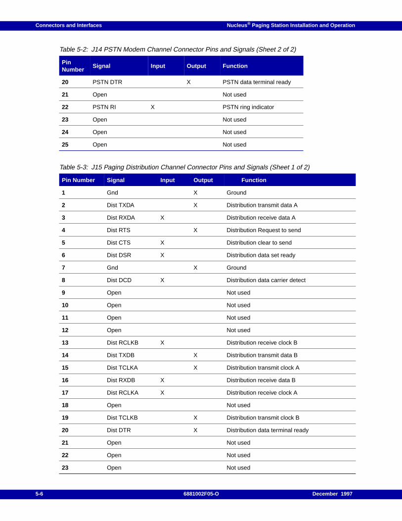
Connectors and Interfaces Nucleus ® Paging Station Installation and Operation
20 PSTN DTR X PSTN data terminal ready
21 Open Not used
22 PSTN RI X PSTN ring indicator
23 Open Not used
24 Open Not used
25 Open Not used
Table 5-3: J15 Paging Distribution Channel Connector Pins and Signals (Sheet 1 of 2)
Pin Number Signal Input Output Function
1 Gnd X Ground
2 Dist TXDA X Distribution transmit data A
3 Dist RXDA X Distribution receive data A
4 Dist RTS X Distribution Request to send
5 Dist CTS X Distribution clear to send
6 Dist DSR X Distribution data set ready
7 Gnd X Ground
8 Dist DCD X Distribution data carrier detect
9 Open Not used
10 Open Not used
11 Open Not used
12 Open Not used
13 Dist RCLKB X Distribution receive clock B
14 Dist TXDB X Distribution transmit data B
15 Dist TCLKA X Distribution transmit clock A
16 Dist RXDB X Distribution receive data B
17 Dist RCLKA X Distribution receive clock A
18 Open Not used
19 Dist TCLKB X Distribution transmit clock B
20 Dist DTR X Distribution data terminal ready
21 Open Not used
22 Open Not used
23 Open Not used
Table 5-2: J14 PSTN Modem Channel Connector Pins and Signals (Sheet 2 of 2)
PinNumber
Signal Input Output Function
5-6 6881002F05-O December 1997
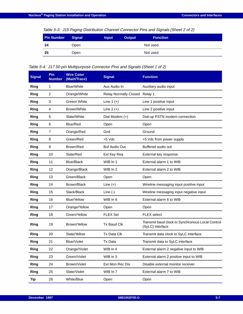
Nucleus ® Paging Station Installation and Operation Connectors and Interfaces
24 Open Not used
25 Open Not used
Table 5-4: J17 50-pin Multipurpose Connector Pins and Signals (Sheet 1 of 2)
SignalPinNumber
Wire Color(Main/Trace)
Signal Function
Ring 1 Blue/White Aux Audio In Auxiliary audio input
Ring 2 Orange/White Relay Normally Closed Relay 1
Ring 3 Green/ White Line 1 (+) Line 1 positive input
Ring 4 Brown/White Line 2 (+) Line 2 positive input
Ring 5 Slate/White Dial Modem (+) Dial-up PSTN modem connection
Ring 6 Blue/Red Open Open
Ring 7 Orange/Red Gnd Ground
Ring 8 Green/Red +5 Vdc +5 Vdc from power supply
Ring 9 Brown/Red Buf Audio Out Buffered audio out
Ring 10 Slate/Red Ext Key Req External key response
Ring 11 Blue/Black WIB In 1 External alarm 1 to WIB
Ring 12 Orange/Black WIB In 2 External alarm 2 to WIB
Ring 13 Green/Black Open Open
Ring 14 Brown/Black Line (+) Wireline messaging input positive input
Ring 15 Slack/Black Line (-) Wireline messaging input negative input
Ring 16 Blue/Yellow WIB In 6 External alarm 6 to WIB
Ring 17 Orange/Yellow Open Open
Ring 18 Green/Yellow FLEX Sel FLEX select
Ring 19 Brown/Yellow Tx Baud ClkTransmit baud clock to Synchronous Local Control(SyLC) interface
Ring 20 Slate/Yellow Tx Data Clk Transmit data clock to SyLC interface
Ring 21 Blue/Violet Tx Data Transmit data to SyLC interface
Ring 22 Orange/Violet WIB in 4 External alarm 2 negative input to WIB
Ring 23 Green/Violet WIB in 3 External alarm 2 positive input to WIB
Ring 24 Brown/Violet Ext Mon Rec Dis Disable external monitor receiver
Ring 25 Slate/Violet WIB In 7 External alarm 7 to WIB
Tip 26 White/Blue Open Open
Table 5-3: J15 Paging Distribution Channel Connector Pins and Signals (Sheet 2 of 2)
Pin Number Signal Input Output Function
December 1997 6881002F05-O 5-7
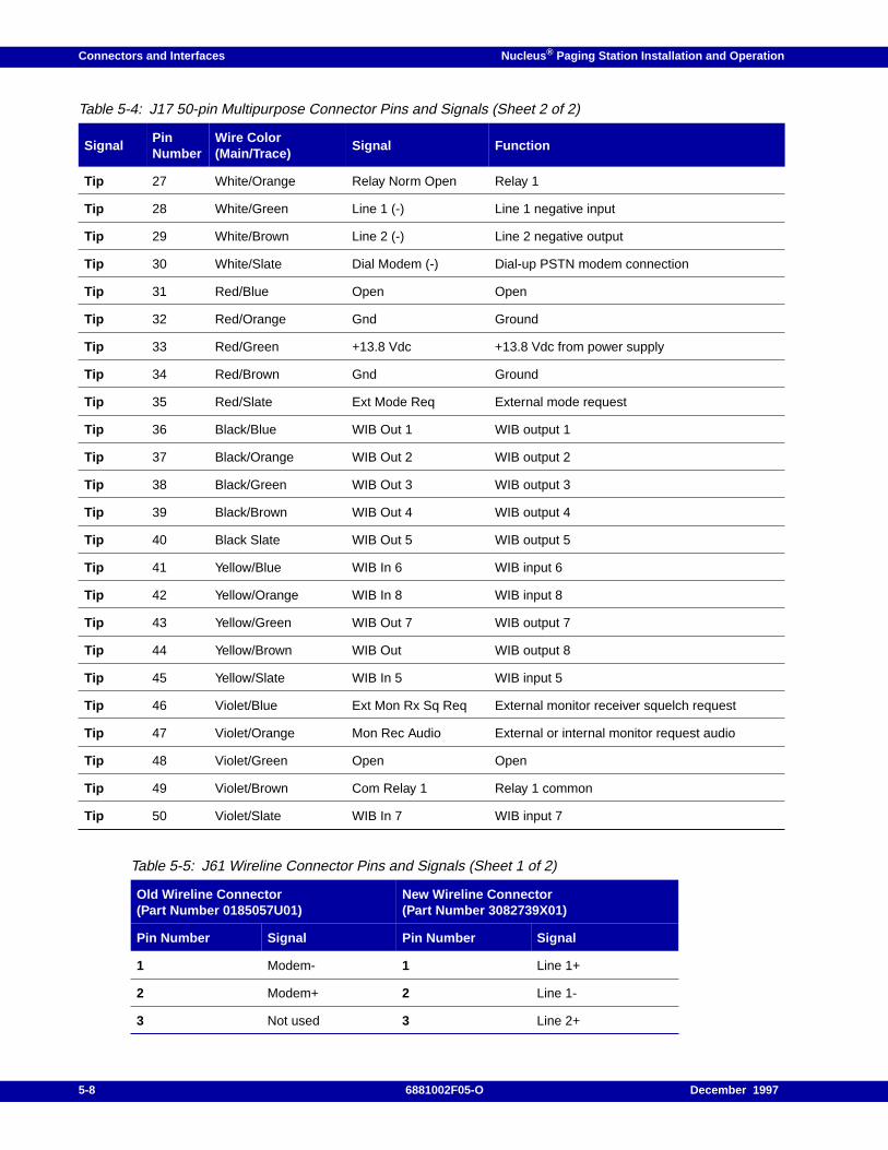
Connectors and Interfaces Nucleus ® Paging Station Installation and Operation
Tip 27 White/Orange Relay Norm Open Relay 1
Tip 28 White/Green Line 1 (-) Line 1 negative input
Tip 29 White/Brown Line 2 (-) Line 2 negative output
Tip 30 White/Slate Dial Modem (-) Dial-up PSTN modem connection
Tip 31 Red/Blue Open Open
Tip 32 Red/Orange Gnd Ground
Tip 33 Red/Green +13.8 Vdc +13.8 Vdc from power supply
Tip 34 Red/Brown Gnd Ground
Tip 35 Red/Slate Ext Mode Req External mode request
Tip 36 Black/Blue WIB Out 1 WIB output 1
Tip 37 Black/Orange WIB Out 2 WIB output 2
Tip 38 Black/Green WIB Out 3 WIB output 3
Tip 39 Black/Brown WIB Out 4 WIB output 4
Tip 40 Black Slate WIB Out 5 WIB output 5
Tip 41 Yellow/Blue WIB In 6 WIB input 6
Tip 42 Yellow/Orange WIB In 8 WIB input 8
Tip 43 Yellow/Green WIB Out 7 WIB output 7
Tip 44 Yellow/Brown WIB Out WIB output 8
Tip 45 Yellow/Slate WIB In 5 WIB input 5
Tip 46 Violet/Blue Ext Mon Rx Sq Req External monitor receiver squelch request
Tip 47 Violet/Orange Mon Rec Audio External or internal monitor request audio
Tip 48 Violet/Green Open Open
Tip 49 Violet/Brown Com Relay 1 Relay 1 common
Tip 50 Violet/Slate WIB In 7 WIB input 7
Table 5-5: J61 Wireline Connector Pins and Signals (Sheet 1 of 2)
Old Wireline Connector(Part Number 0185057U01)
New Wireline Connector(Part Number 3082739X01)
Pin Number Signal Pin Number Signal
1 Modem- 1 Line 1+
2 Modem+ 2 Line 1-
3 Not used 3 Line 2+
Table 5-4: J17 50-pin Multipurpose Connector Pins and Signals (Sheet 2 of 2)
SignalPinNumber
Wire Color(Main/Trace)
Signal Function
5-8 6881002F05-O December 1997
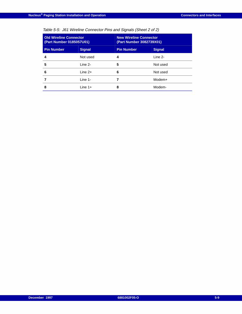
Nucleus ® Paging Station Installation and Operation Connectors and Interfaces
4 Not used 4 Line 2-
5 Line 2- 5 Not used
6 Line 2+ 6 Not used
7 Line 1- 7 Modem+
8 Line 1+ 8 Modem-
Table 5-5: J61 Wireline Connector Pins and Signals (Sheet 2 of 2)
Old Wireline Connector(Part Number 0185057U01)
New Wireline Connector(Part Number 3082739X01)
Pin Number Signal Pin Number Signal
December 1997 6881002F05-O 5-9
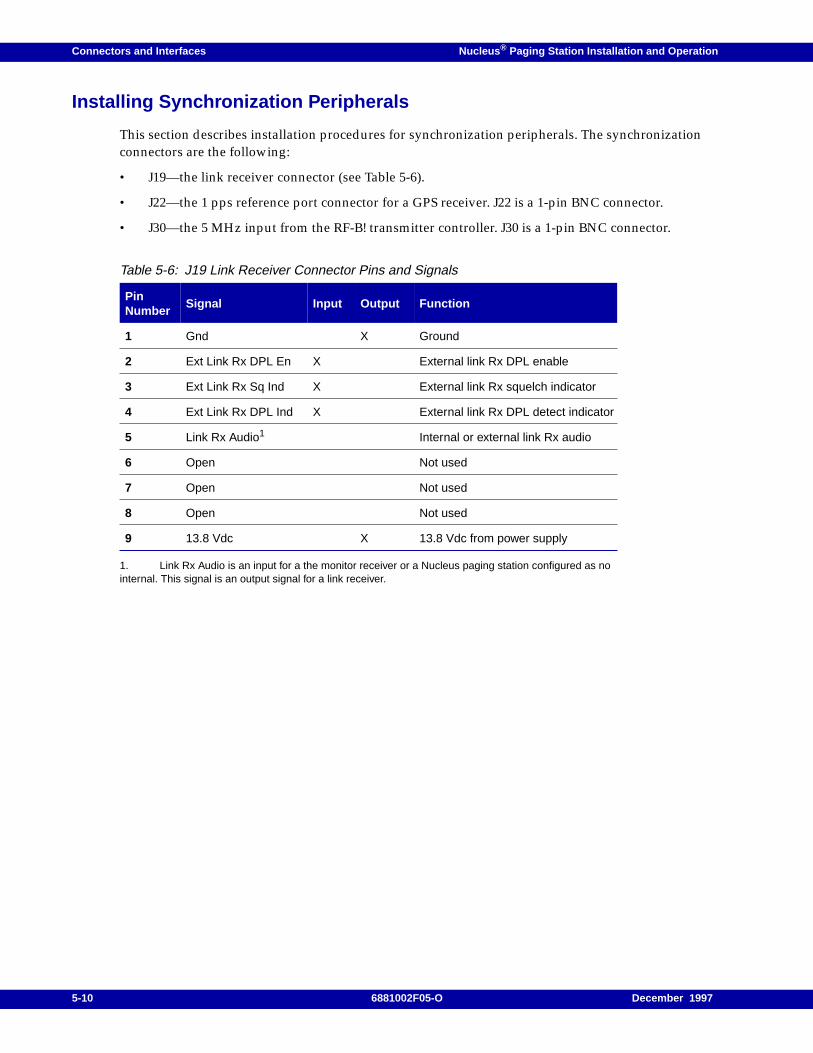
Connectors and Interfaces Nucleus ® Paging Station Installation and Operation
Installing Synchronization Peripherals
This section describes installation procedures for synchronization peripherals. The synchronizationconnectors are the following:
• J19—the link receiver connector (see Table 5-6).
• J22—the 1 pps reference port connector for a GPS receiver. J22 is a 1-pin BNC connector.
• J30—the 5 MHz input from the RF-B! transmitter controller. J30 is a 1-pin BNC connector.
1. Link Rx Audio is an input for a the monitor receiver or a Nucleus paging station configured as nointernal. This signal is an output signal for a link receiver.
Table 5-6: J19 Link Receiver Connector Pins and Signals
PinNumber
Signal Input Output Function
1 Gnd X Ground
2 Ext Link Rx DPL En X External link Rx DPL enable
3 Ext Link Rx Sq Ind X External link Rx squelch indicator
4 Ext Link Rx DPL Ind X External link Rx DPL detect indicator
5 Link Rx Audio1 Internal or external link Rx audio
6 Open Not used
7 Open Not used
8 Open Not used
9 13.8 Vdc X 13.8 Vdc from power supply
5-10 6881002F05-O December 1997
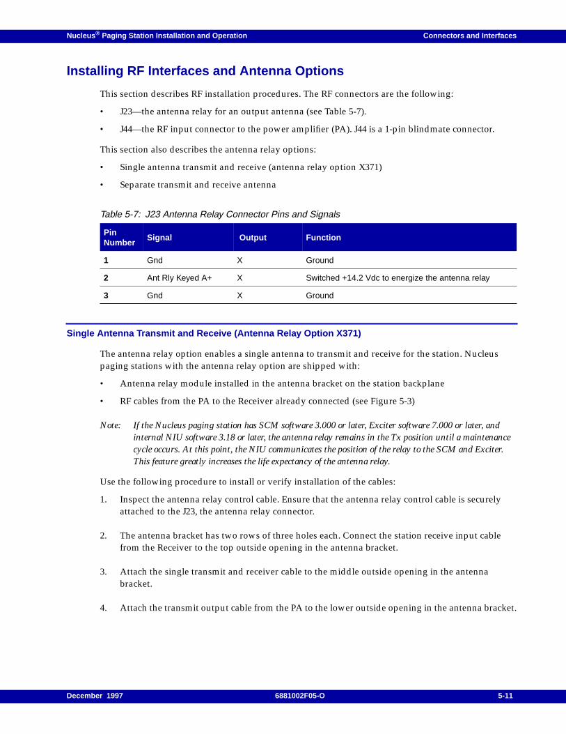
Nucleus ® Paging Station Installation and Operation Connectors and Interfaces
Installing RF Interfaces and Antenna Options
This section describes RF installation procedures. The RF connectors are the following:
• J23—the antenna relay for an output antenna (see Table 5-7).
• J44—the RF input connector to the power amplifier (PA). J44 is a 1-pin blindmate connector.
This section also describes the antenna relay options:
• Single antenna transmit and receive (antenna relay option X371)
• Separate transmit and receive antenna
Single Antenna Transmit and Receive (Antenna Relay Option X371)
The antenna relay option enables a single antenna to transmit and receive for the station. Nucleuspaging stations with the antenna relay option are shipped with:
• Antenna relay module installed in the antenna bracket on the station backplane
• RF cables from the PA to the Receiver already connected (see Figure 5-3)
Note: If the Nucleus paging station has SCM software 3.000 or later, Exciter software 7.000 or later, andinternal NIU software 3.18 or later, the antenna relay remains in the Tx position until a maintenancecycle occurs. At this point, the NIU communicates the position of the relay to the SCM and Exciter.This feature greatly increases the life expectancy of the antenna relay.
Use the following procedure to install or verify installation of the cables:
1. Inspect the antenna relay control cable. Ensure that the antenna relay control cable is securelyattached to the J23, the antenna relay connector.
2. The antenna bracket has two rows of three holes each. Connect the station receive input cablefrom the Receiver to the top outside opening in the antenna bracket.
3. Attach the single transmit and receiver cable to the middle outside opening in the antennabracket.
4. Attach the transmit output cable from the PA to the lower outside opening in the antenna bracket.
Table 5-7: J23 Antenna Relay Connector Pins and Signals
PinNumber
Signal Output Function
1 Gnd X Ground
2 Ant Rly Keyed A+ X Switched +14.2 Vdc to energize the antenna relay
3 Gnd X Ground
December 1997 6881002F05-O 5-11
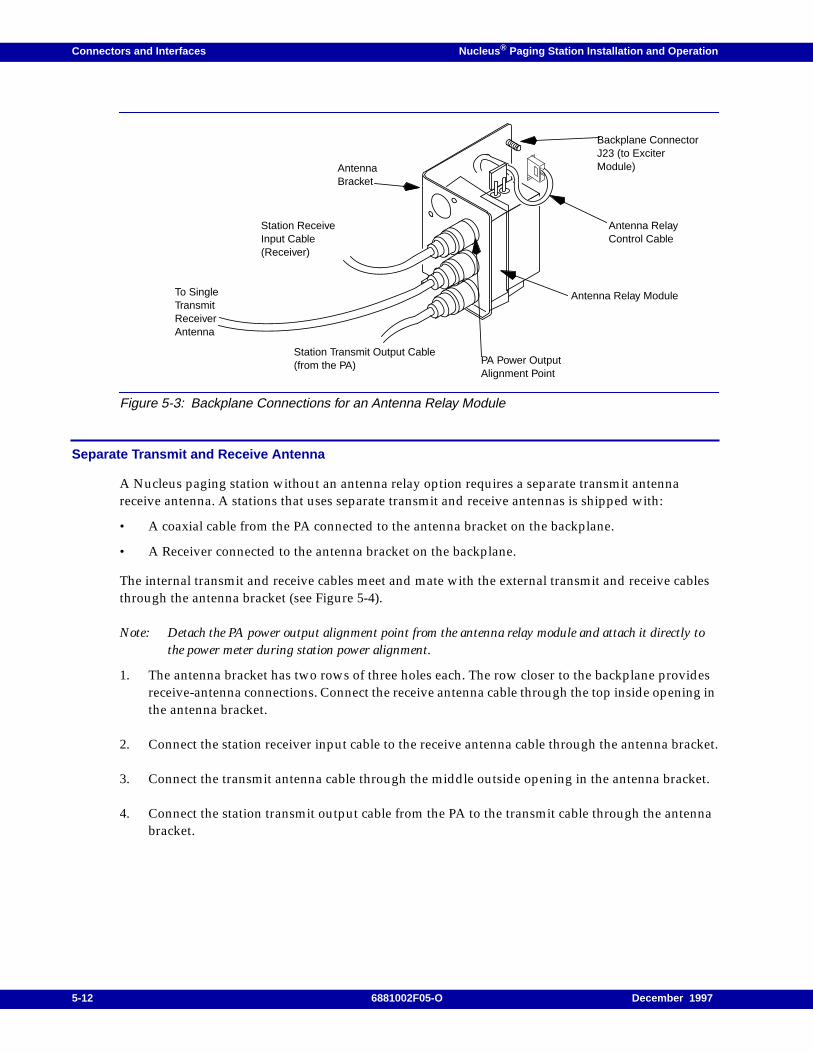
Connectors and Interfaces Nucleus ® Paging Station Installation and Operation
Figure 5-3: Backplane Connections for an Antenna Relay Module
Separate Transmit and Receive Antenna
A Nucleus paging station without an antenna relay option requires a separate transmit antennareceive antenna. A stations that uses separate transmit and receive antennas is shipped with:
• A coaxial cable from the PA connected to the antenna bracket on the backplane.
• A Receiver connected to the antenna bracket on the backplane.
The internal transmit and receive cables meet and mate with the external transmit and receive cablesthrough the antenna bracket (see Figure 5-4).
Note: Detach the PA power output alignment point from the antenna relay module and attach it directly tothe power meter during station power alignment.
1. The antenna bracket has two rows of three holes each. The row closer to the backplane providesreceive-antenna connections. Connect the receive antenna cable through the top inside opening inthe antenna bracket.
2. Connect the station receiver input cable to the receive antenna cable through the antenna bracket.
3. Connect the transmit antenna cable through the middle outside opening in the antenna bracket.
4. Connect the station transmit output cable from the PA to the transmit cable through the antennabracket.
To SingleTransmitReceiverAntenna
Station Transmit Output Cable(from the PA)
Station ReceiveInput Cable(Receiver)
Antenna RelayControl Cable
PA Power OutputAlignment Point
Antenna Relay Module
Backplane ConnectorJ23 (to ExciterModule)Antenna
Bracket
5-12 6881002F05-O December 1997
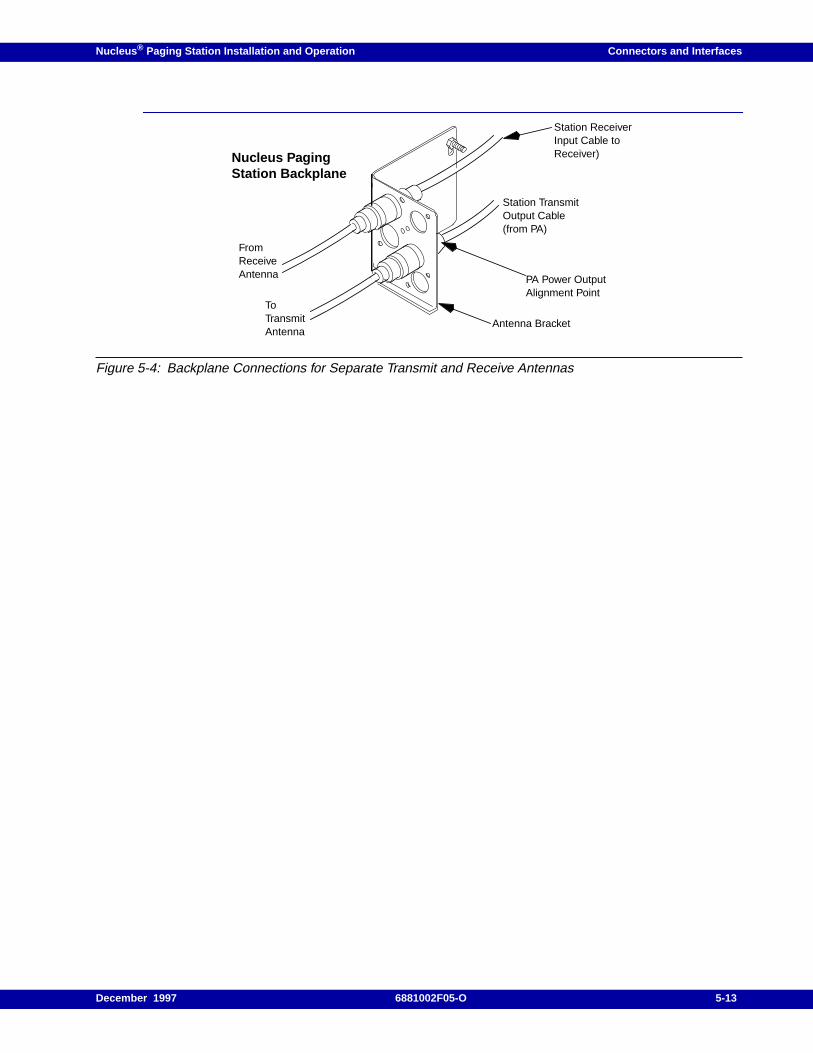
Nucleus ® Paging Station Installation and Operation Connectors and Interfaces
Figure 5-4: Backplane Connections for Separate Transmit and Receive Antennas
FromReceiveAntenna
ToTransmitAntenna
Station TransmitOutput Cable(from PA)
Station ReceiverInput Cable toReceiver)
PA Power OutputAlignment Point
Antenna Bracket
Nucleus PagingStation Backplane
December 1997 6881002F05-O 5-13
Connectors and Interfaces Nucleus ® Paging Station Installation and Operation
Installing Power
This section describes power installation procedures. The power connectors include the following:
• Ground at the ground lug on the antenna bracket.
• J31—the DC power to fan(s) and external devices (see Table 5-8).
• J50—the AC input to all stations. J50 is a 3-prong receptacle suitable to the site country, anddesignated during the ordering procedure.
• J51—the AC input high power stations. J51 is a 3-prong receptacle suitable to the site country, anddesignated during the ordering procedure.
• J24—the battery temperature measurement to the station (Table 5-9).
• J25—the battery revert during AC power failures for standard power stations. See paragraph,"Standard Power Station Battery Revert".
• J26—the battery revert during AC power failures for high power stations. See paragraph, "HighPower Station Battery Revert".
Note: Always install battery options after installing AC power.
Table 5-8: J31 DC Power Connector Pins and Signals
Pin Number Signal Input Output Function
1 Gnd X Ground
2 Gnd X Ground
3 5 Vdc X 5 Vdc from power supply
4 5 Vdc X 5 Vdc from power supply
5 13.8 Vdc X 13.8 Vdc from power supply
6 13.8 Vdc X 13.8 Vdc from power supply
7 28 Vdc X 28 Vdc from power supply
8 Gnd X Ground
9 28 Vdc X 28 Vdc from power supply
10 Gnd X Ground
Table 5-9: J24 Battery Temperature Connector Pins and Signals
PinNumber
Signal Input Output Function
1 Gnd X Ground
2 Batt Temp XVariable resistance proportional to batterytemperature
3 Gnd X Ground
5-14 6881002F05-O December 1997
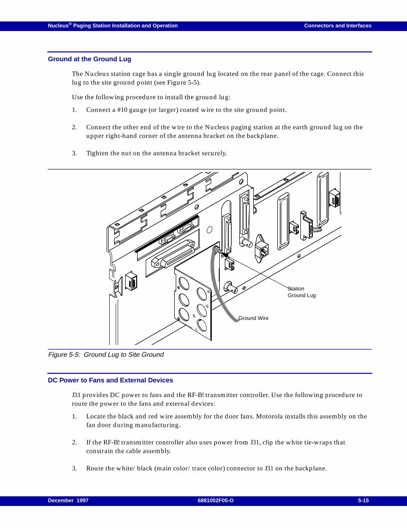
Nucleus ® Paging Station Installation and Operation Connectors and Interfaces
Ground at the Ground Lug
The Nucleus station cage has a single ground lug located on the rear panel of the cage. Connect thislug to the site ground point (see Figure 5-5).
Use the following procedure to install the ground lug:
1. Connect a #10 gauge (or larger) coated wire to the site ground point.
2. Connect the other end of the wire to the Nucleus paging station at the earth ground lug on theupper right-hand corner of the antenna bracket on the backplane.
3. Tighten the nut on the antenna bracket securely.
Figure 5-5: Ground Lug to Site Ground
DC Power to Fans and External Devices
J31 provides DC power to fans and the RF-B! transmitter controller. Use the following procedure toroute the power to the fans and external devices:
1. Locate the black and red wire assembly for the door fans. Motorola installs this assembly on thefan door during manufacturing.
2. If the RF-B! transmitter controller also uses power from J31, clip the white tie-wraps thatconstrain the cable assembly.
3. Route the white/black (main color/trace color) connector to J31 on the backplane.
StationGround Lug
Ground Wire
December 1997 6881002F05-O 5-15
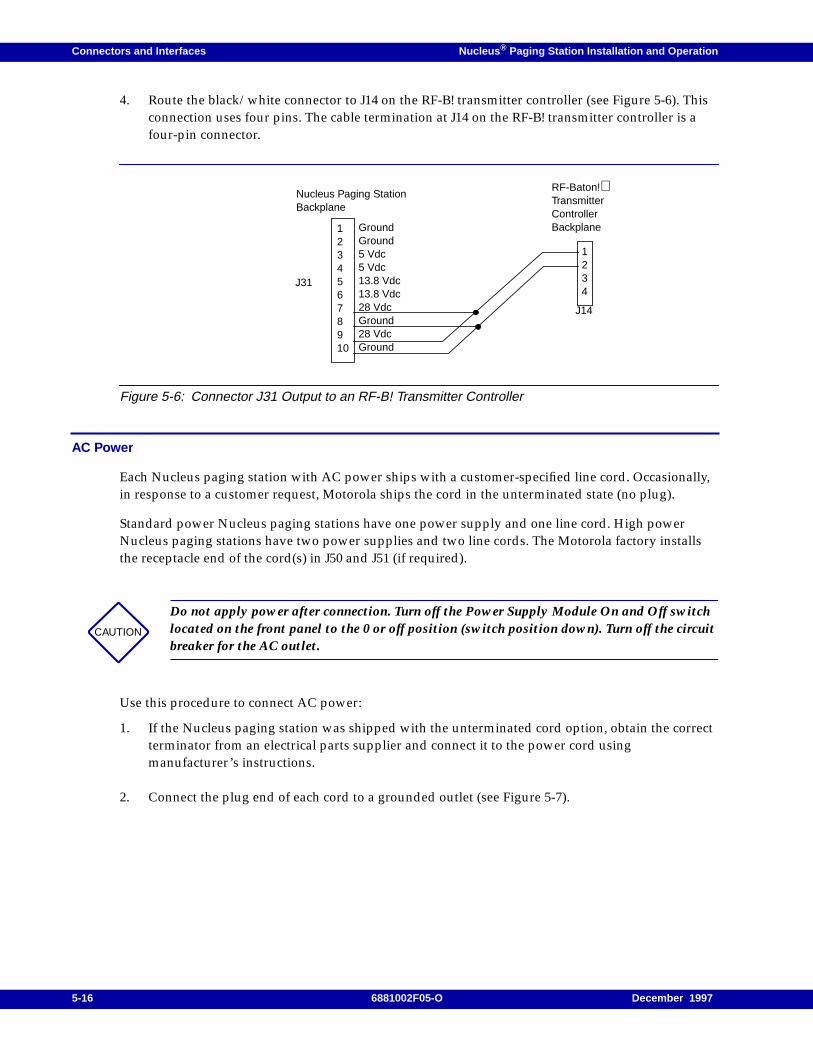
Connectors and Interfaces Nucleus ® Paging Station Installation and Operation
4. Route the black/white connector to J14 on the RF-B! transmitter controller (see Figure 5-6). Thisconnection uses four pins. The cable termination at J14 on the RF-B! transmitter controller is afour-pin connector.
Figure 5-6: Connector J31 Output to an RF-B! Transmitter Controller
AC Power
Each Nucleus paging station with AC power ships with a customer-specified line cord. Occasionally,in response to a customer request, Motorola ships the cord in the unterminated state (no plug).
Standard power Nucleus paging stations have one power supply and one line cord. High powerNucleus paging stations have two power supplies and two line cords. The Motorola factory installsthe receptacle end of the cord(s) in J50 and J51 (if required).
Use this procedure to connect AC power:
1. If the Nucleus paging station was shipped with the unterminated cord option, obtain the correctterminator from an electrical parts supplier and connect it to the power cord usingmanufacturer’s instructions.
2. Connect the plug end of each cord to a grounded outlet (see Figure 5-7).
CAUTION
Do not apply power after connection. Turn off the Power Supply Module On and Off switchlocated on the front panel to the 0 or off position (switch position down). Turn off the circuitbreaker for the AC outlet.
1234
J14
12345678910
RF-Baton!TransmitterControllerBackplane
Nucleus Paging StationBackplane
J31
GroundGround5 Vdc5 Vdc13.8 Vdc13.8 Vdc28 VdcGround28 VdcGround
5-16 6881002F05-O December 1997
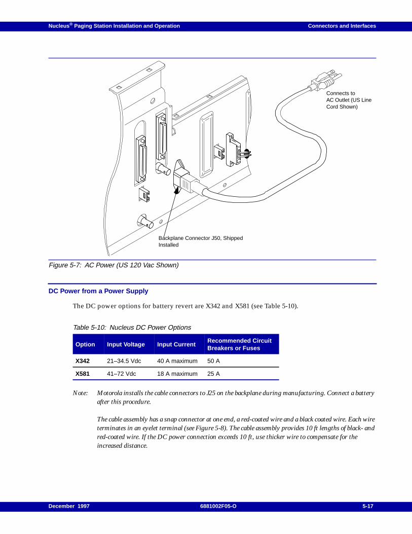
Nucleus ® Paging Station Installation and Operation Connectors and Interfaces
Figure 5-7: AC Power (US 120 Vac Shown)
DC Power from a Power Supply
The DC power options for battery revert are X342 and X581 (see Table 5-10).
Note: Motorola installs the cable connectors to J25 on the backplane during manufacturing. Connect a batteryafter this procedure.
The cable assembly has a snap connector at one end, a red-coated wire and a black coated wire. Each wireterminates in an eyelet terminal (see Figure 5-8). The cable assembly provides 10 ft lengths of black- andred-coated wire. If the DC power connection exceeds 10 ft, use thicker wire to compensate for theincreased distance.
Table 5-10: Nucleus DC Power Options
Option Input Voltage Input CurrentRecommended CircuitBreakers or Fuses
X342 21–34.5 Vdc 40 A maximum 50 A
X581 41–72 Vdc 18 A maximum 25 A
Backplane Connector J50, ShippedInstalled
Connects toAC Outlet (US LineCord Shown)
December 1997 6881002F05-O 5-17
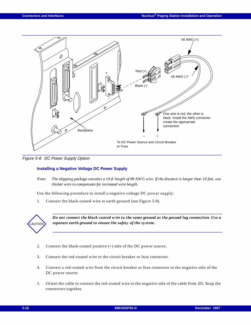
Connectors and Interfaces Nucleus ® Paging Station Installation and Operation
Figure 5-8: DC Power Supply Option
Installing a Negative Voltage DC Power Supply
Note: The shipping package contains a 10-ft length of #8 AWG wire. If the distance is longer than 10 feet, usethicker wire to compensate for increased wire length.
Use the following procedure to install a negative voltage DC power supply:
1. Connect the black-coated wire to earth ground (see Figure 5-9).
2. Connect the black-coated positive (+) side of the DC power source.
3. Connect the red-coated wire to the circuit breaker or fuse connector.
4. Connect a red-coated wire from the circuit breaker or fuse connector to the negative side of theDC power source.
5. Orient the cable to connect the red-coated wire to the negative side of the cable from J25. Snap theconnectors together.
CAUTION
Do not connect the black coated wire to the same ground as the ground lug connection. Use aseparate earth ground to ensure the safety of the system.
Backplane
+–
#8 AWG (-)*
#8 AWG (+)
Red (+)
Black (-)
To DC Power Source and Circuit Breakeror Fuse
One wire is red, the other isblack. Install the AWG connectorcreate the appropriateconnection
5-18 6881002F05-O December 1997
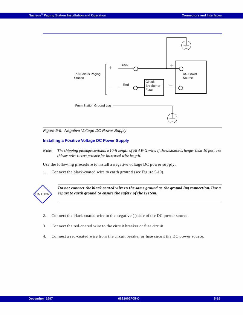
Nucleus ® Paging Station Installation and Operation Connectors and Interfaces
Figure 5-9: Negative Voltage DC Power Supply
Installing a Positive Voltage DC Power Supply
Note: The shipping package contains a 10-ft length of #8 AWG wire. If the distance is longer than 10 feet, usethicker wire to compensate for increased wire length.
Use the following procedure to install a negative voltage DC power supply:
1. Connect the black-coated wire to earth ground (see Figure 5-10).
2. Connect the black-coated wire to the negative (-) side of the DC power source.
3. Connect the red-coated wire to the circuit breaker or fuse circuit.
4. Connect a red-coated wire from the circuit breaker or fuse circuit the DC power source.
CAUTION
Do not connect the black coated wire to the same ground as the ground lug connection. Use aseparate earth ground to ensure the safety of the system.
CircuitBreaker orFuse
DC PowerSource
From Station Ground Lug
Red
Black
To Nucleus PagingStation
December 1997 6881002F05-O 5-19
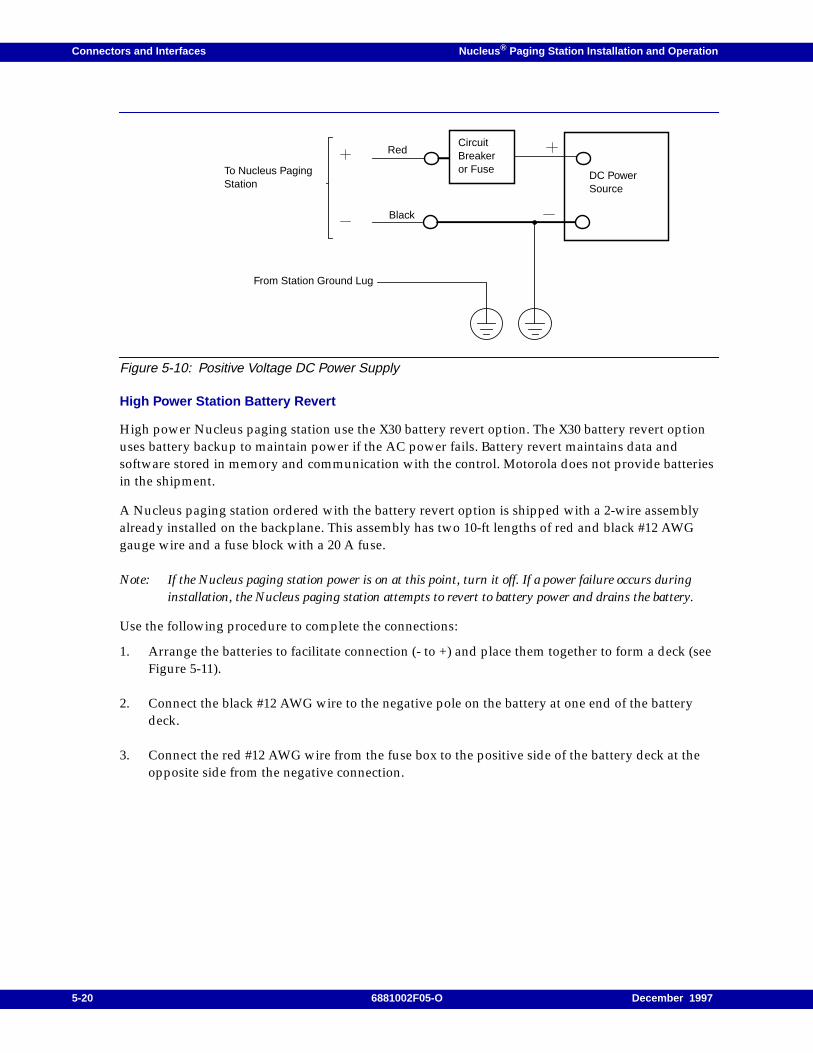
Connectors and Interfaces Nucleus ® Paging Station Installation and Operation
Figure 5-10: Positive Voltage DC Power Supply
High Power Station Battery Revert
High power Nucleus paging station use the X30 battery revert option. The X30 battery revert optionuses battery backup to maintain power if the AC power fails. Battery revert maintains data andsoftware stored in memory and communication with the control. Motorola does not provide batteriesin the shipment.
A Nucleus paging station ordered with the battery revert option is shipped with a 2-wire assemblyalready installed on the backplane. This assembly has two 10-ft lengths of red and black #12 AWGgauge wire and a fuse block with a 20 A fuse.
Note: If the Nucleus paging station power is on at this point, turn it off. If a power failure occurs duringinstallation, the Nucleus paging station attempts to revert to battery power and drains the battery.
Use the following procedure to complete the connections:
1. Arrange the batteries to facilitate connection (- to +) and place them together to form a deck (seeFigure 5-11).
2. Connect the black #12 AWG wire to the negative pole on the battery at one end of the batterydeck.
3. Connect the red #12 AWG wire from the fuse box to the positive side of the battery deck at theopposite side from the negative connection.
DC PowerSource
From Station Ground Lug
Black
RedCircuitBreakeror FuseTo Nucleus Paging
Station
5-20 6881002F05-O December 1997
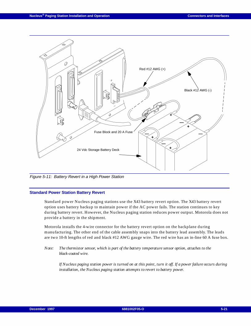
Nucleus ® Paging Station Installation and Operation Connectors and Interfaces
Figure 5-11: Battery Revert in a High Power Station
Standard Power Station Battery Revert
Standard power Nucleus paging stations use the X43 battery revert option. The X43 battery revertoption uses battery backup to maintain power if the AC power fails. The station continues to keyduring battery revert. However, the Nucleus paging station reduces power output. Motorola does notprovide a battery in the shipment.
Motorola installs the 4-wire connector for the battery revert option on the backplane duringmanufacturing. The other end of the cable assembly snaps into the battery lead assembly. The leadsare two 10-ft lengths of red and black #12 AWG gauge wire. The red wire has an in-line 60 A fuse box.
Note: The thermistor sensor, which is part of the battery temperature sensor option, attaches to theblack-coated wire.
If Nucleus paging station power is turned on at this point, turn it off. If a power failure occurs duringinstallation, the Nucleus paging station attempts to revert to battery power.
+
—
24 Vdc Storage Battery Deck
Black #12 AWG (-)
Red #12 AWG (+)
Fuse Block and 20 A Fuse
+
——+
—+
December 1997 6881002F05-O 5-21
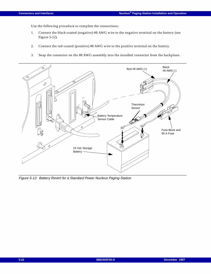
Connectors and Interfaces Nucleus ® Paging Station Installation and Operation
Use the following procedure to complete the connections:
1. Connect the black-coated (negative) #8 AWG wire to the negative terminal on the battery (seeFigure 5-12).
2. Connect the red-coated (positive) #8 AWG wire to the positive terminal on the battery.
3. Snap the connector on the #8 AWG assembly into the installed connector from the backplane.
Figure 5-12: Battery Revert for a Standard Power Nucleus Paging Station
24 Vdc StorageBattery
+
—
Black#8 AWG (-)
Red #8 AWG (+)
Fuse Block and60 A Fuse
ThermistorSensor
Battery TemperatureSensor Cable
5-22 6881002F05-O December 1997
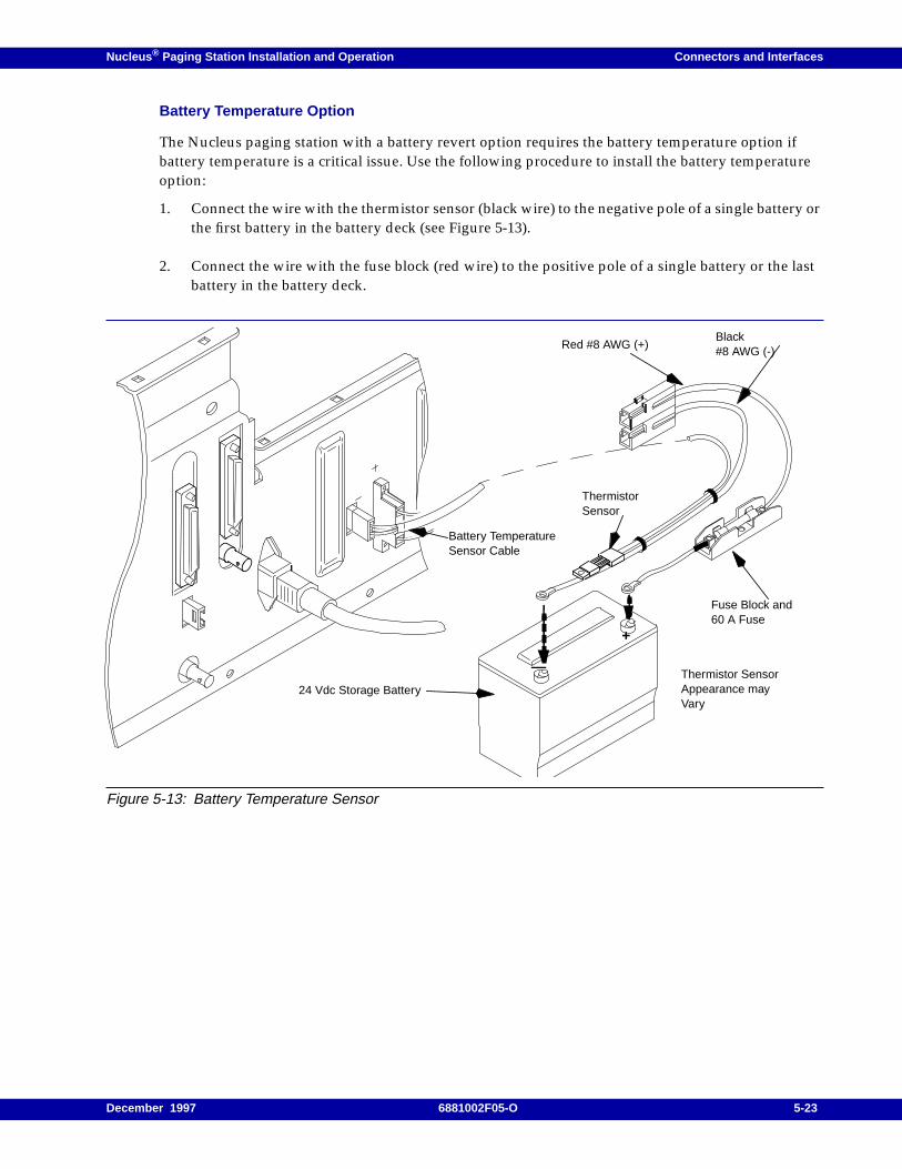
Nucleus ® Paging Station Installation and Operation Connectors and Interfaces
Battery Temperature Option
The Nucleus paging station with a battery revert option requires the battery temperature option ifbattery temperature is a critical issue. Use the following procedure to install the battery temperatureoption:
1. Connect the wire with the thermistor sensor (black wire) to the negative pole of a single battery orthe first battery in the battery deck (see Figure 5-13).
2. Connect the wire with the fuse block (red wire) to the positive pole of a single battery or the lastbattery in the battery deck.
Figure 5-13: Battery Temperature Sensor
24 Vdc Storage Battery
+
—
Black#8 AWG (-)
Red #8 AWG (+)
Fuse Block and60 A Fuse
ThermistorSensor
Battery TemperatureSensor Cable
Thermistor SensorAppearance mayVary
December 1997 6881002F05-O 5-23
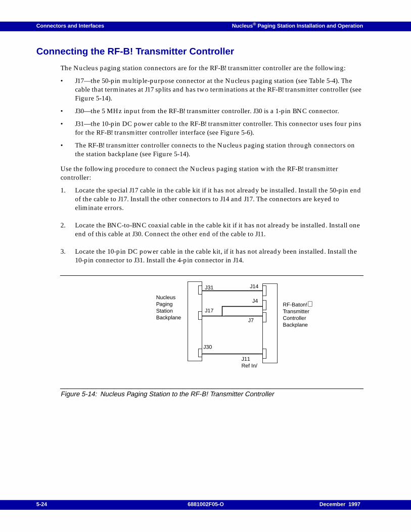
Connectors and Interfaces Nucleus ® Paging Station Installation and Operation
Connecting the RF-B! Transmitter Controller
The Nucleus paging station connectors are for the RF-B! transmitter controller are the following:
• J17—the 50-pin multiple-purpose connector at the Nucleus paging station (see Table 5-4). Thecable that terminates at J17 splits and has two terminations at the RF-B! transmitter controller (seeFigure 5-14).
• J30—the 5 MHz input from the RF-B! transmitter controller. J30 is a 1-pin BNC connector.
• J31—the 10-pin DC power cable to the RF-B! transmitter controller. This connector uses four pinsfor the RF-B! transmitter controller interface (see Figure 5-6).
• The RF-B! transmitter controller connects to the Nucleus paging station through connectors onthe station backplane (see Figure 5-14).
Use the following procedure to connect the Nucleus paging station with the RF-B! transmittercontroller:
1. Locate the special J17 cable in the cable kit if it has not already be installed. Install the 50-pin endof the cable to J17. Install the other connectors to J14 and J17. The connectors are keyed toeliminate errors.
2. Locate the BNC-to-BNC coaxial cable in the cable kit if it has not already be installed. Install oneend of this cable at J30. Connect the other end of the cable to J11.
3. Locate the 10-pin DC power cable in the cable kit, if it has not already been installed. Install the10-pin connector to J31. Install the 4-pin connector in J14.
Figure 5-14: Nucleus Paging Station to the RF-B! Transmitter Controller
RF-Baton!TransmitterControllerBackplane
NucleusPagingStationBackplane
J17
J31 J14
J4
J7
J30
J11Ref In/
5-24 6881002F05-O December 1997
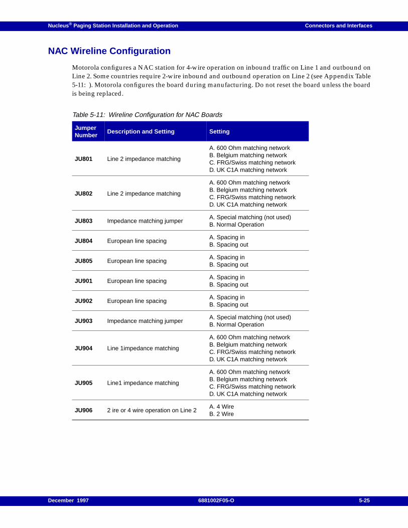
Nucleus ® Paging Station Installation and Operation Connectors and Interfaces
NAC Wireline Configuration
Motorola configures a NAC station for 4-wire operation on inbound traffic on Line 1 and outbound onLine 2. Some countries require 2-wire inbound and outbound operation on Line 2 (see Appendix Table5-11: ). Motorola configures the board during manufacturing. Do not reset the board unless the boardis being replaced.
Table 5-11: Wireline Configuration for NAC Boards
JumperNumber
Description and Setting Setting
JU801 Line 2 impedance matching
A. 600 Ohm matching networkB. Belgium matching networkC. FRG/Swiss matching networkD. UK C1A matching network
JU802 Line 2 impedance matching
A. 600 Ohm matching networkB. Belgium matching networkC. FRG/Swiss matching networkD. UK C1A matching network
JU803 Impedance matching jumperA. Special matching (not used)B. Normal Operation
JU804 European line spacingA. Spacing inB. Spacing out
JU805 European line spacingA. Spacing inB. Spacing out
JU901 European line spacingA. Spacing inB. Spacing out
JU902 European line spacingA. Spacing inB. Spacing out
JU903 Impedance matching jumperA. Special matching (not used)B. Normal Operation
JU904 Line 1impedance matching
A. 600 Ohm matching networkB. Belgium matching networkC. FRG/Swiss matching networkD. UK C1A matching network
JU905 Line1 impedance matching
A. 600 Ohm matching networkB. Belgium matching networkC. FRG/Swiss matching networkD. UK C1A matching network
JU906 2 ire or 4 wire operation on Line 2A. 4 WireB. 2 Wire
December 1997 6881002F05-O 5-25

Connectors and Interfaces Nucleus ® Paging Station Installation and Operation
5-26 6881002F05-O December 1997
Nucleus ® Paging Station Installation and Operation / Chapter 6
Front Panel Indicators and Controls 6
This chapter describes the front panel indicators and controls that provide maintenance control andoperating information for the Nucleus paging station and Nucleus paging Station with AdvancedControl (NAC). This chapter contains the following information:
Control Module Front Panel, 6-2SCM Front Panel, 6-2NAC Front Panel, 6-3Front Panel LED Display, 6-4Keypad Functions, 6-4SCM Front Panel LEDs, 6-7NAC Front Panel LEDs, 6-7SCM Serial Port, 6-8SCM Reference Frequency Port, 6-8
LEDs on Other Modules, 6-9Exciter LEDs, 6-9Power Supply LEDs, 6-10
December 1997 6881002F05-O 6-1
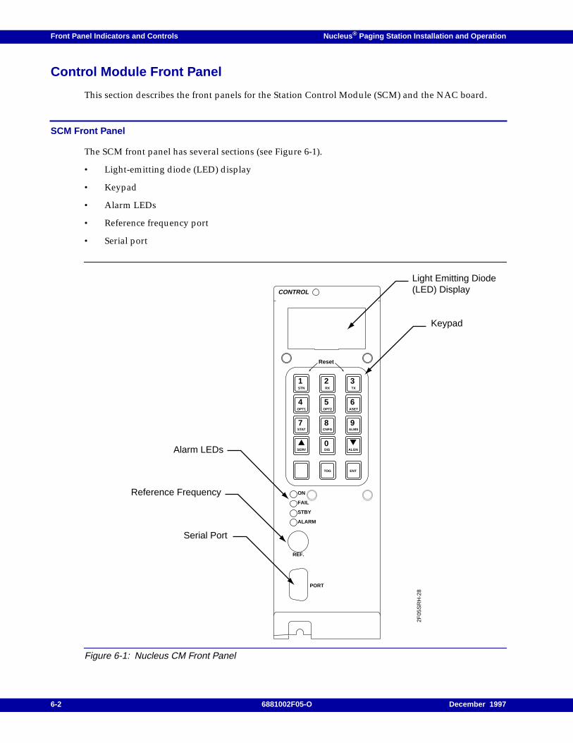
Front Panel Indicators and Controls Nucleus ® Paging Station Installation and Operation
Control Module Front Panel
This section describes the front panels for the Station Control Module (SCM) and the NAC board.
SCM Front Panel
The SCM front panel has several sections (see Figure 6-1).
• Light-emitting diode (LED) display
• Keypad
• Alarm LEDs
• Reference frequency port
• Serial port
Figure 6-1: Nucleus CM Front Panel
CONTROL
ON
FAIL
STBY
ALARM
REF.
PORT
1STN
2RX
3TX
4OPT1
5OPT2
6ASET
7STAT
SERV
8CNFG
9ALMS
ALGN0DIS
ENTTOG
Reset
Light Emitting Diode(LED) Display
Keypad
Alarm LEDs
Reference Frequency
Serial Port
2F05
SR
H-2
8
6-2 6881002F05-O December 1997
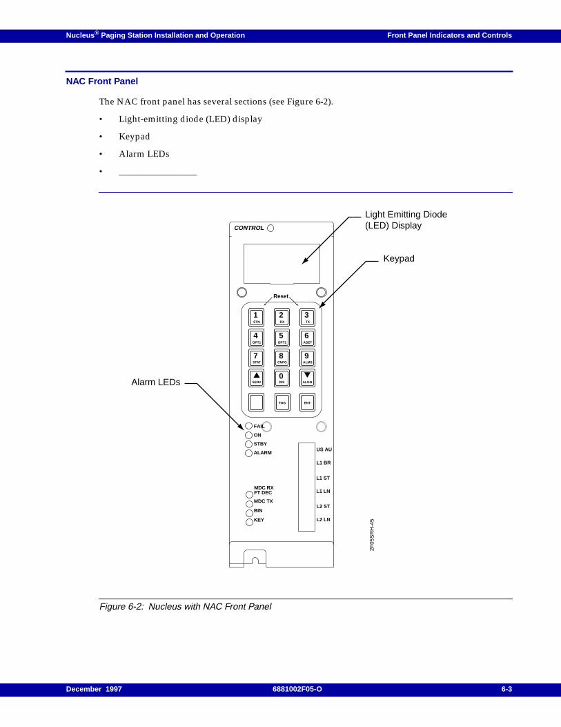
Nucleus ® Paging Station Installation and Operation Front Panel Indicators and Controls
NAC Front Panel
The NAC front panel has several sections (see Figure 6-2).
• Light-emitting diode (LED) display
• Keypad
• Alarm LEDs
• _________________
Figure 6-2: Nucleus with NAC Front Panel
CONTROL
1STN
2RX
3TX
4OPT1
5OPT2
6ASET
7STAT
SERV
8CNFG
9ALMS
ALGN0DIS
ENTTOG
Reset
Light Emitting Diode(LED) Display
Keypad
Alarm LEDs2F
05S
RH
-45
FAIL
ON
STBY
ALARMUS AU
L1 BR
L1 ST
L1 LN
L2 ST
L2 LN
MDC RXFT DEC
MDC TX
BIN
KEY
December 1997 6881002F05-O 6-3
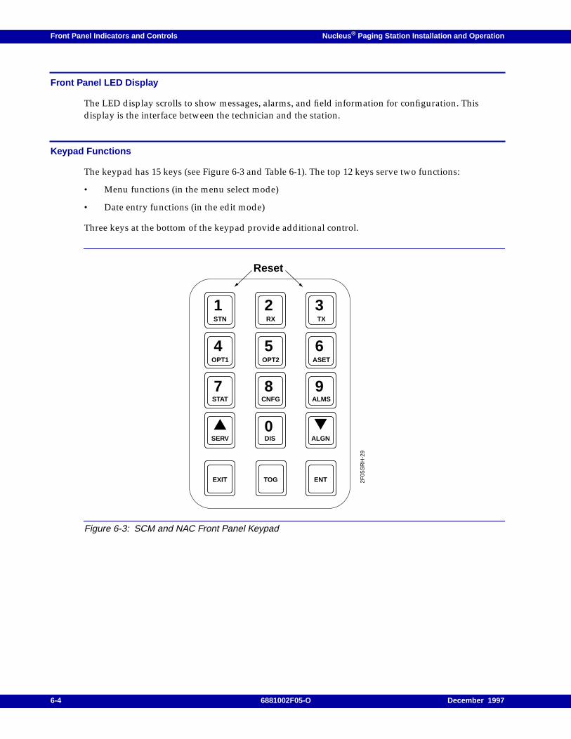
Front Panel Indicators and Controls Nucleus ® Paging Station Installation and Operation
Front Panel LED Display
The LED display scrolls to show messages, alarms, and field information for configuration. Thisdisplay is the interface between the technician and the station.
Keypad Functions
The keypad has 15 keys (see Figure 6-3 and Table 6-1). The top 12 keys serve two functions:
• Menu functions (in the menu select mode)
• Date entry functions (in the edit mode)
Three keys at the bottom of the keypad provide additional control.
Figure 6-3: SCM and NAC Front Panel Keypad
1STN
2RX
3TX
4OPT1
5OPT2
6ASET
7STAT
SERV
8CNFG
9ALMS
ALGN0DIS
ENTTOGEXIT
Reset
2F05
SR
H-2
9
6-4 6881002F05-O December 1997
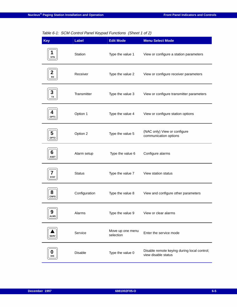
Nucleus ® Paging Station Installation and Operation Front Panel Indicators and Controls
Table 6-1: SCM Control Panel Keypad Functions (Sheet 1 of 2)
Key Label Edit Mode Menu Select Mode
Station Type the value 1 View or configure a station parameters
Receiver Type the value 2 View or configure receiver parameters
Transmitter Type the value 3 View or configure transmitter parameters
Option 1 Type the value 4 View or configure station options
Option 2 Type the value 5(NAC only) View or configurecommunication options
Alarm setup Type the value 6 Configure alarms
Status Type the value 7 View station status
Configuration Type the value 8 View and configure other parameters
Alarms Type the value 9 View or clear alarms
ServiceMove up one menuselection
Enter the service mode
Disable Type the value 0Disable remote keying during local control;view disable status
1STN
2RX
3TX
4OPT1
5OPT2
6ASET
7STAT
8CNFG
9ALMS
SERV
0DIS
December 1997 6881002F05-O 6-5
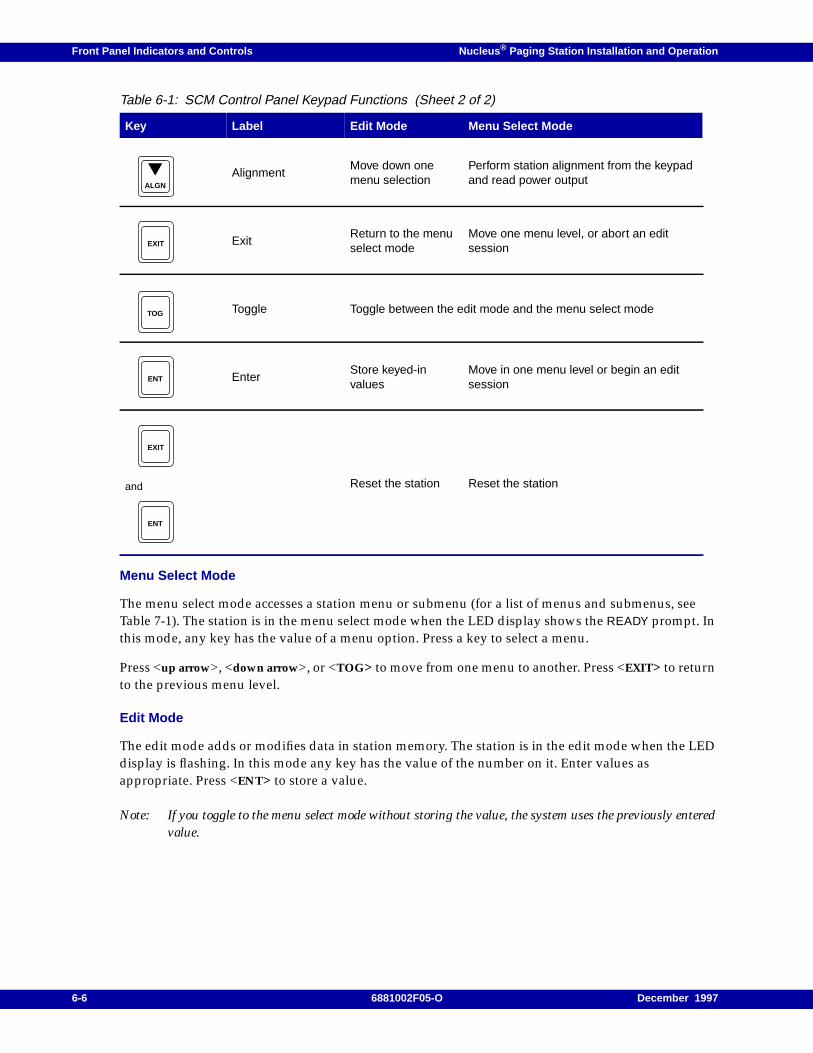
Front Panel Indicators and Controls Nucleus ® Paging Station Installation and Operation
Menu Select Mode
The menu select mode accesses a station menu or submenu (for a list of menus and submenus, seeTable 7-1). The station is in the menu select mode when the LED display shows the READY prompt. Inthis mode, any key has the value of a menu option. Press a key to select a menu.
Press <up arrow>, <down arrow>, or <TOG> to move from one menu to another. Press <EXIT> to returnto the previous menu level.
Edit Mode
The edit mode adds or modifies data in station memory. The station is in the edit mode when the LEDdisplay is flashing. In this mode any key has the value of the number on it. Enter values asappropriate. Press <ENT> to store a value.
Note: If you toggle to the menu select mode without storing the value, the system uses the previously enteredvalue.
AlignmentMove down onemenu selection
Perform station alignment from the keypadand read power output
ExitReturn to the menuselect mode
Move one menu level, or abort an editsession
Toggle Toggle between the edit mode and the menu select mode
EnterStore keyed-invalues
Move in one menu level or begin an editsession
and Reset the station Reset the station
Table 6-1: SCM Control Panel Keypad Functions (Sheet 2 of 2)
Key Label Edit Mode Menu Select Mode
ALGN
EXIT
TOG
ENT
EXIT
ENT
6-6 6881002F05-O December 1997
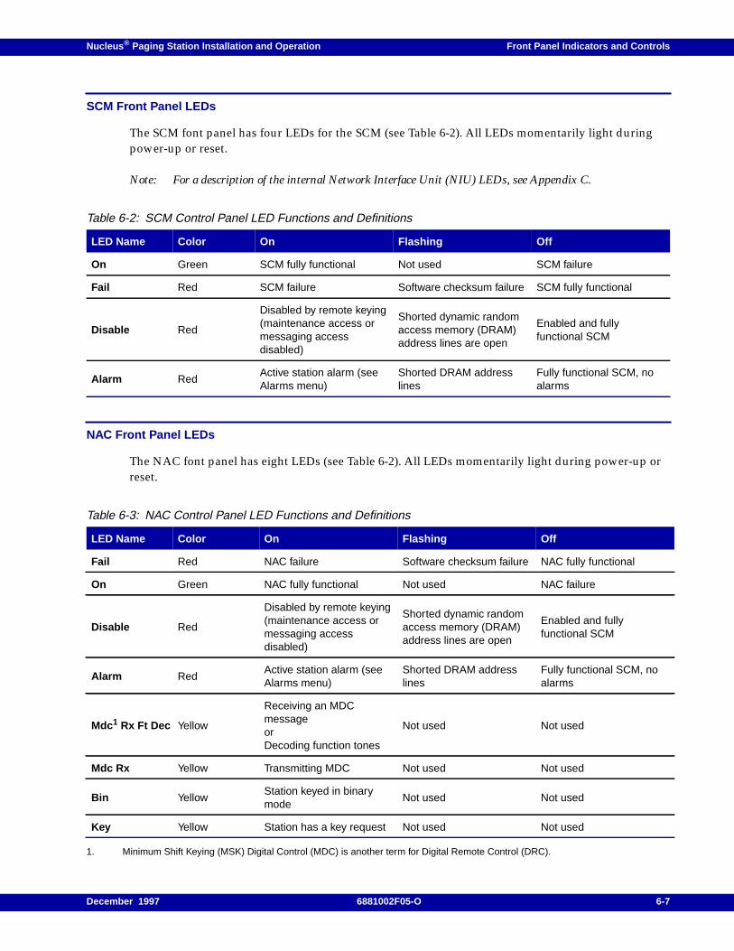
Nucleus ® Paging Station Installation and Operation Front Panel Indicators and Controls
SCM Front Panel LEDs
The SCM font panel has four LEDs for the SCM (see Table 6-2). All LEDs momentarily light duringpower-up or reset.
Note: For a description of the internal Network Interface Unit (NIU) LEDs, see Appendix C.
NAC Front Panel LEDs
The NAC font panel has eight LEDs (see Table 6-2). All LEDs momentarily light during power-up orreset.
1. Minimum Shift Keying (MSK) Digital Control (MDC) is another term for Digital Remote Control (DRC).
Table 6-2: SCM Control Panel LED Functions and Definitions
LED Name Color On Flashing Off
On Green SCM fully functional Not used SCM failure
Fail Red SCM failure Software checksum failure SCM fully functional
Disable Red
Disabled by remote keying(maintenance access ormessaging accessdisabled)
Shorted dynamic randomaccess memory (DRAM)address lines are open
Enabled and fullyfunctional SCM
Alarm RedActive station alarm (seeAlarms menu)
Shorted DRAM addresslines
Fully functional SCM, noalarms
Table 6-3: NAC Control Panel LED Functions and Definitions
LED Name Color On Flashing Off
Fail Red NAC failure Software checksum failure NAC fully functional
On Green NAC fully functional Not used NAC failure
Disable Red
Disabled by remote keying(maintenance access ormessaging accessdisabled)
Shorted dynamic randomaccess memory (DRAM)address lines are open
Enabled and fullyfunctional SCM
Alarm RedActive station alarm (seeAlarms menu)
Shorted DRAM addresslines
Fully functional SCM, noalarms
Mdc1 Rx Ft Dec Yellow
Receiving an MDCmessageorDecoding function tones
Not used Not used
Mdc Rx Yellow Transmitting MDC Not used Not used
Bin YellowStation keyed in binarymode
Not used Not used
Key Yellow Station has a key request Not used Not used
December 1997 6881002F05-O 6-7
Front Panel Indicators and Controls Nucleus ® Paging Station Installation and Operation
SCM Serial Port
The serial port is a 9-pin connector for serial access to the station from a laptop computer running anemulation program.
SCM Reference Frequency Port
The Ref. Freq. port is a 1-pin connector for injecting a reference frequency into the SCM.
6-8 6881002F05-O December 1997
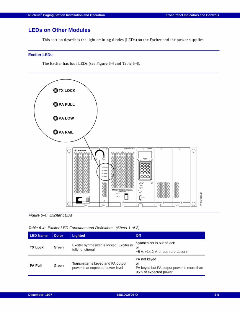
Nucleus ® Paging Station Installation and Operation Front Panel Indicators and Controls
LEDs on Other Modules
This section describes the light emitting diodes (LEDs) on the Exciter and the power supplies.
Exciter LEDs
The Exciter has four LEDs (see Figure 6-4 and Table 6-4).
Figure 6-4: Exciter LEDs
Table 6-4: Exciter LED Functions and Definitions (Sheet 1 of 2)
LED Name Color Lighted Off
TX Lock GreenExciter synthesizer is locked; Exciter isfully functional.
Synthesizer is out of lockor+5 V, +14.2 V, or both are absent
PA Full GreenTransmitter is keyed and PA outputpower is at expected power level
PA not keyedorPA keyed but PA output power is more than95% of expected power
POWER SUPPLY
WARNING DISCONNECT battery (if battery equipped)and turn OFF power supply before removingor inserting any module.
FAIL
ON
CONTROL
ON
FAIL
STBY
ALARM
REF.
PORT
TX LOCK
PA FULL
PA LOW
PA FAIL
2F05
SR
H-4
6
POWER AMPLIFIER EXCITER
1 2 3
4 5 6
7 8 9
0
EXIT TOG ENT
Reset
TX LOCK
PA FULL
PA LOW
PA FAIL
December 1997 6881002F05-O 6-9
Front Panel Indicators and Controls Nucleus ® Paging Station Installation and Operation
Power Supply LEDs
Each power supply has two LEDs (see Figure 6-5 and Table 6-5). The Module Fail LED on each powersupply lights during start-up and then turns off.
Note: The high power station has two power supplies. Each power supply has the LEDs described here.
PA Low YellowTransmitter is keyed and PA outputpower is less than expected power levelbut not shut down
PA not keyedorPA keyed and PA output power is less than95% of expected power
PA Fail Red
(ON)No PA output power (example: PAshutdown mode)orLED status is latched (status duringcurrent key or for previous key)orFault in one or more of the PA fansorFinal PA VSWR Alarm is activated
PA output power is at expected level or atspecific cutback levels (any level other thanshutdown)orLED status is latched (status during currentkey or for previous key)
PA Fail Red(FLASHING) when PA Test Mode isactive
PA is functioning normally
Table 6-4: Exciter LED Functions and Definitions (Sheet 2 of 2)
LED Name Color Lighted Off
6-10 6881002F05-O December 1997
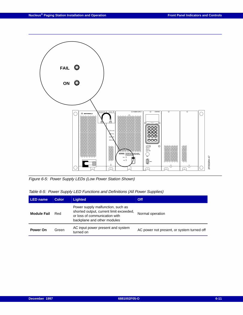
Nucleus ® Paging Station Installation and Operation Front Panel Indicators and Controls
Figure 6-5: Power Supply LEDs (Low Power Station Shown)
Table 6-5: Power Supply LED Functions and Definitions (All Power Supplies)
LED name Color Lighted Off
Module Fail Red
Power supply malfunction, such asshorted output, current limit exceeded,or loss of communication withbackplane and other modules
Normal operation
Power On GreenAC input power present and systemturned on
AC power not present, or system turned off
POWER SUPPLY
WARNING DISCONNECT battery (if battery equipped)and turn OFF power supply before removingor inserting any module.
FAIL
ON
CONTROL
ON
FAIL
STBY
ALARM
REF.
PORT
TX LOCK
PA FULL
PA LOW
PA FAIL
2F05
SR
H-4
7
POWER AMPLIFIER EXCITER
1 2 3
4 5 6
7 8 9
0
EXIT TOG ENT
Reset
FAIL
ON
December 1997 6881002F05-O 6-11

Front Panel Indicators and Controls Nucleus ® Paging Station Installation and Operation
6-12 6881002F05-O December 1997
Nucleus ® Paging Station Installation and Operation / Chapter 7
Basic Keypad Procedures 7
This chapter describes basic keyboard access for the Nucleus paging station. This chapter contains thefollowing information:
Conventions, 7-2
Accessing the LED Display, 7-3
Changing the Password, 7-4
Disabling or Enabling the Password, 7-5Disabling the Password, 7-5Enabling the Password, 7-5
Changing Parameters from the Keypad, 7-6
The Menus, 7-8
December 1997 6881002F05-O 7-1
Basic Keypad Procedures Nucleus ® Paging Station Installation and Operation
Conventions
Several chapters that follow describe work with the menus and selections that appear in thelight-emitting diode (LED) display on the keypad. These chapters are:
• SCM configuration (see Chapter 8, "SCM Station Configuration")
• SCM alarms, status, troubleshooting, and alignment (see Chapter 9, "SCM Station Alarms, Status,Troubleshooting, and Alignment")
• NAC configuration (see Chapter 10, "NAC Configuration")
• NAC alignment and simulcast equalization (see Chapter 11, "NAC Alignment and Equalization")
• NAC alarm configuration and management (see Chapter 12, "NAC Alarm Configuration andVerification")
• Receivers (see Appendix E)
These chapters use the notational conventions to describe activities with the LED and the keypad (seeTable 7-1).
Table 7-1: Notational Conventions for Presenting Software Procedures
Item Enclosed in Printed in Examples
SCM or NAC front panelkeys
Angle brackets (<>) 9 point Palatino Bold<TX><STN><down arrow>
Station output Not enclosed 9 point Helvetica
EXT CIRCULATOR: NOTPRESENTRX TYPE: INTERNAL MONITOROPERATING POWER: yyy W
User input Not enclosed 9 point Helvetica boldEnabledDisabled
Starting point in aprocedure
Not enclosed 9 point Helvetica READY prompt
End point in a procedure As required As required
Press <EXIT> once to return to theTX CHN FREQS prompt.
Press <EXIT> twice to return to theREADY prompt.
7-2 6881002F05-O December 1997
Nucleus ® Paging Station Installation and Operation Basic Keypad Procedures
Accessing the LED Display
After start-up, use this procedure to gain access to the LED display on the SCM or NAC panel:
1. From a blank display, press any key on the SCM or NAC front panel keypad.
If the station has the password enabled, see Step . If the station has the password disabled, theLED display shows the READY prompt. Continue with other procedures.
Note: To enable the password feature, see paragraph, “Enabling the Password”.
If the station has the password enabled, the LED display shows the READY - ENTER PASSWORDprompt.
2. Type the password on the number keys.
3. Press <ENT>. (The default password is 6000.)
The LED display shows the READY prompt.
The LED display has a screen saver. After five minutes without input, the LED display goesblank. Perform the procedure again to regain access.
Note: If you change the password, display the value to confirm it before the LED display screen saver timerexpires and the LED display goes blank.
If you forget your password, the Nucleus paging station denies access. Call MotorolaOne-Call-Support.
December 1997 6881002F05-O 7-3
Basic Keypad Procedures Nucleus ® Paging Station Installation and Operation
Changing the Password
Use the following procedure to change the password at the station.
1. From the READY prompt, press <STN>. The system accesses the Station menu.
2. At the TX FREQ RANGE prompt, press <up arrow> or <down arrow> to access the password:
PASSWORD xxxx
Where xxxx is the current password.
3. Press <ENT>.
The text flashes to show the system is in the edit mode.
4. Type the new password (in the range 0000 through 9999). Press <ENT>.
The LED display shows the new password:
PASSWORD yyyy
Where yyyy is the new password.
5. Press <EXIT> twice to return to the READY prompt.
7-4 6881002F05-O December 1997
Nucleus ® Paging Station Installation and Operation Basic Keypad Procedures
Disabling or Enabling the Password
This section describes the procedures for controlling the password.
Disabling the Password
Use this procedure to disable the password:
1. From the READY prompt, press <STN>. The system accesses the Station menu.
2. At the TX FREQ RANGE prompt, press <up arrow> or <down arrow> to access the password:
The display shows the current status of the password:
FRONT PANEL PASSWORD: ENABLED
3. Press <ENT>. The message flashes to show the system is in the edit mode.
4. Press <TOG> to select Disable . The message continues to flash.
5. Press <STN>. The message stops flashing and shows the new password status:
FRONT PANEL PASSWORD: DISABLED
6. Press <EXIT> twice to return to the READY prompt.
Enabling the Password
Use this procedure to enable the password:
1. From the READY prompt, press <STN>. The system accesses the Station menu.
2. At the TX FREQ RANGE prompt, press <up arrow> or <down arrow> to access the password:
The display shows the current status of the password:
FRONT PANEL PASSWORD: DISABLED
3. Press <ENT>. The message flashes to show the system is in the edit mode.
4. Press <TOG>. The message continues to flash.
5. Press <ENT>. The text stops flashing and shows the new password status:
FRONT PANEL PASSWORD: ENABLED
6. Press <EXIT> twice to return to the READY prompt.
December 1997 6881002F05-O 7-5
Basic Keypad Procedures Nucleus ® Paging Station Installation and Operation
Changing Parameters from the Keypad
When the LED display shows the READY prompt, the system is in the menu select mode. The menusare organized in a hierarchy. All menus have submenus and many submenus have further selections(see Figure 7-1 for the SCM menus and Step 7-2 for the NAC menus). Use this general procedure towork with the menus.
Note: The system shows alignment channels from the Station menu. However, the values are set duringalignment procedures from the Station Alignment menu. Do not attempt to set them from the Stationmenu.
All menus are structured hierarchically (see Figure 7-1, Table 7-2, and Table 7-2). Use the followingprocedure for working in these menus:
1. In Table 7-2, the first column, Menu Name, refers to the name of a key on the SCM front panel.
2. When you select the menu name, the display shows the first item in the second column. This isthe first item in the column entitled Submenu Name.
3. When the display shows the first submenu name, press <down arrow> to scroll to the nextsubmenu name in the menu.
4. As each submenu appears, the display shows the value that is currently stored in memory for thesubmenu item.
5. To change the value, press <ENT>.
6. If the value is a simple number, type the new value on the keypad. Press <ENT> to store the value.For example, in Figure 7-1, the value for the password is 6000. To replace this value, type the newvalue and press <ENT>.
7. If the value is one of a list, press <down arrow> to scroll through all the available values in the list.Press <ENT> to select and store the new value. For example, in Figure 7-1, the values for theCURRENT TX CHN are 1 through 8. Press <down arrow> to scroll through these values. Press<ENT> to select the correct one.
8. Occasionally, the selection has one more level of items imbedded in it. For example, the TX menuhas a SPECIAL TX SETUP submenu. The SPECIAL TX SETUP submenu has a list of selections; TXDATA INVERT is one of them. An additional level of selection is ENABLED or DISABLED. Press<down arrow> to scroll to one of these values. Press <ENT> to store the value.
9. At the end of each procedure, press <EXIT> until the top level of the menu appears. Press <EXIT>again. The READY prompt appears.
7-6 6881002F05-O December 1997
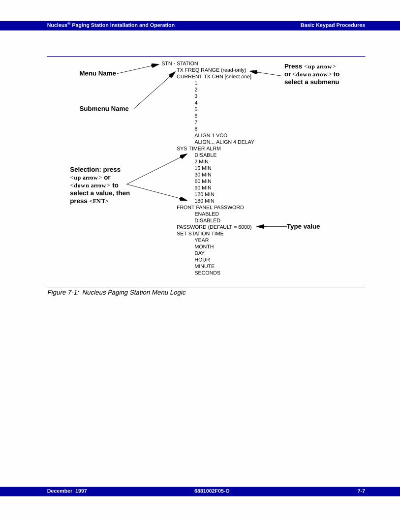
Nucleus ® Paging Station Installation and Operation Basic Keypad Procedures
Figure 7-1: Nucleus Paging Station Menu Logic
STN - STATIONTX FREQ RANGE (read-only)CURRENT TX CHN [select one]
12345678ALIGN 1 VCOALIGN... ALIGN 4 DELAY
SYS TIMER ALRMDISABLE2 MIN15 MIN30 MIN60 MIN90 MIN120 MIN180 MIN
FRONT PANEL PASSWORDENABLEDDISABLED
PASSWORD (DEFAULT = 6000)SET STATION TIME
YEARMONTHDAYHOURMINUTESECONDS
Menu NamePress <up arrow>or <down arrow> toselect a submenu
Submenu Name
Selection: press<up arrow> or<down arrow> toselect a value, thenpress <ENT>
Type value
December 1997 6881002F05-O 7-7
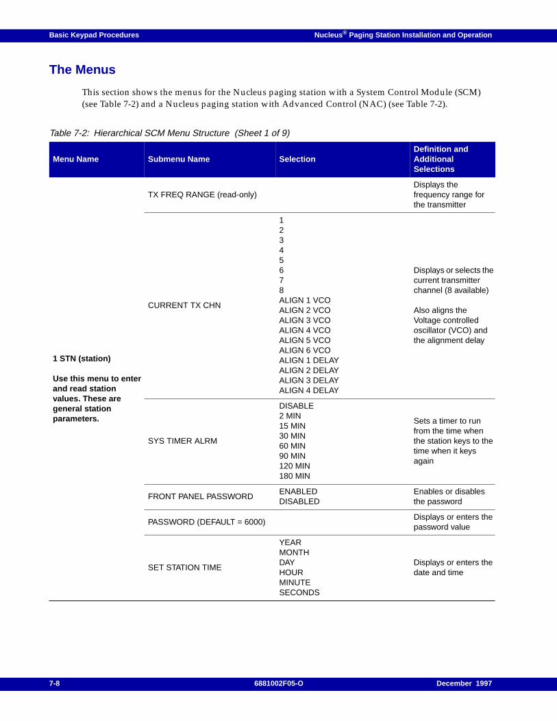
Basic Keypad Procedures Nucleus ® Paging Station Installation and Operation
The Menus
This section shows the menus for the Nucleus paging station with a System Control Module (SCM)(see Table 7-2) and a Nucleus paging station with Advanced Control (NAC) (see Table 7-2).
Table 7-2: Hierarchical SCM Menu Structure (Sheet 1 of 9)
Menu Name Submenu Name SelectionDefinition andAdditionalSelections
1 STN (station)
Use this menu to enterand read stationvalues. These aregeneral stationparameters.
TX FREQ RANGE (read-only)Displays thefrequency range forthe transmitter
CURRENT TX CHN
12345678ALIGN 1 VCOALIGN 2 VCOALIGN 3 VCOALIGN 4 VCOALIGN 5 VCOALIGN 6 VCOALIGN 1 DELAYALIGN 2 DELAYALIGN 3 DELAYALIGN 4 DELAY
Displays or selects thecurrent transmitterchannel (8 available)
Also aligns theVoltage controlledoscillator (VCO) andthe alignment delay
SYS TIMER ALRM
DISABLE2 MIN15 MIN30 MIN60 MIN90 MIN120 MIN180 MIN
Sets a timer to runfrom the time whenthe station keys to thetime when it keysagain
FRONT PANEL PASSWORDENABLEDDISABLED
Enables or disablesthe password
PASSWORD (DEFAULT = 6000)Displays or enters thepassword value
SET STATION TIME
YEARMONTHDAYHOURMINUTESECONDS
Displays or enters thedate and time
7-8 6881002F05-O December 1997
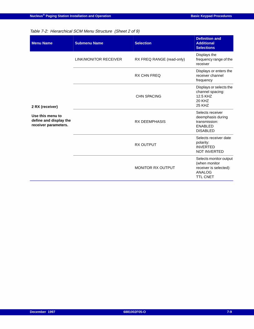
Nucleus ® Paging Station Installation and Operation Basic Keypad Procedures
2 RX (receiver)
Use this menu todefine and display thereceiver parameters.
LINK/MONITOR RECEIVER RX FREQ RANGE (read-only)Displays thefrequency range of thereceiver
RX CHN FREQDisplays or enters thereceiver channelfrequency
CHN SPACING
Displays or selects thechannel spacing:12.5 KHZ20 KHZ25 KHZ
RX DEEMPHASIS
Selects receiverdeemphasis duringtransmission:ENABLEDDISABLED
RX OUTPUT
Selects receiver datepolarity:INVERTEDNOT INVERTED
MONITOR RX OUTPUT
Selects monitor output(when monitorreceiver is selected):ANALOGTTL CNET
Table 7-2: Hierarchical SCM Menu Structure (Sheet 2 of 9)
Menu Name Submenu Name SelectionDefinition andAdditionalSelections
December 1997 6881002F05-O 7-9
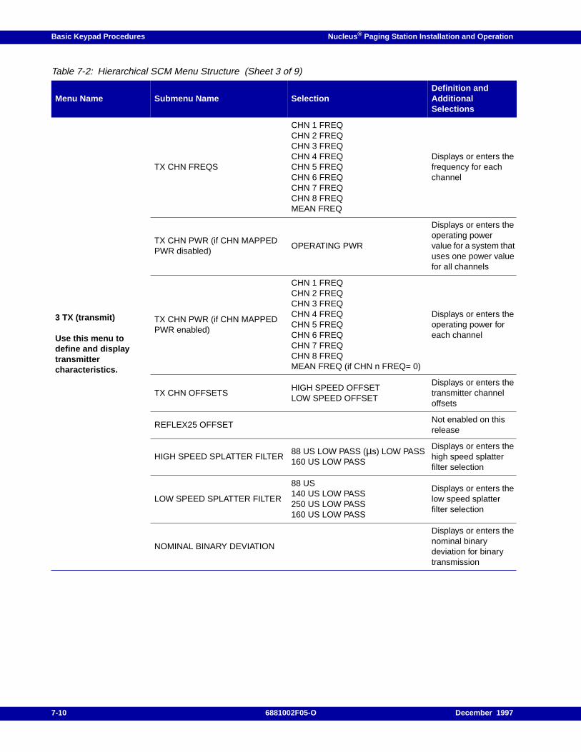
Basic Keypad Procedures Nucleus ® Paging Station Installation and Operation
3 TX (transmit)
Use this menu todefine and displaytransmittercharacteristics.
TX CHN FREQS
CHN 1 FREQCHN 2 FREQCHN 3 FREQCHN 4 FREQCHN 5 FREQCHN 6 FREQCHN 7 FREQCHN 8 FREQMEAN FREQ
Displays or enters thefrequency for eachchannel
TX CHN PWR (if CHN MAPPEDPWR disabled)
OPERATING PWR
Displays or enters theoperating powervalue for a system thatuses one power valuefor all channels
TX CHN PWR (if CHN MAPPEDPWR enabled)
CHN 1 FREQCHN 2 FREQCHN 3 FREQCHN 4 FREQCHN 5 FREQCHN 6 FREQCHN 7 FREQCHN 8 FREQMEAN FREQ (if CHN n FREQ= 0)
Displays or enters theoperating power foreach channel
TX CHN OFFSETSHIGH SPEED OFFSETLOW SPEED OFFSET
Displays or enters thetransmitter channeloffsets
REFLEX25 OFFSETNot enabled on thisrelease
HIGH SPEED SPLATTER FILTER88 US LOW PASS (µs) LOW PASS160 US LOW PASS
Displays or enters thehigh speed splatterfilter selection
LOW SPEED SPLATTER FILTER
88 US140 US LOW PASS250 US LOW PASS160 US LOW PASS
Displays or enters thelow speed splatterfilter selection
NOMINAL BINARY DEVIATION
Displays or enters thenominal binarydeviation for binarytransmission
Table 7-2: Hierarchical SCM Menu Structure (Sheet 3 of 9)
Menu Name Submenu Name SelectionDefinition andAdditionalSelections
7-10 6881002F05-O December 1997
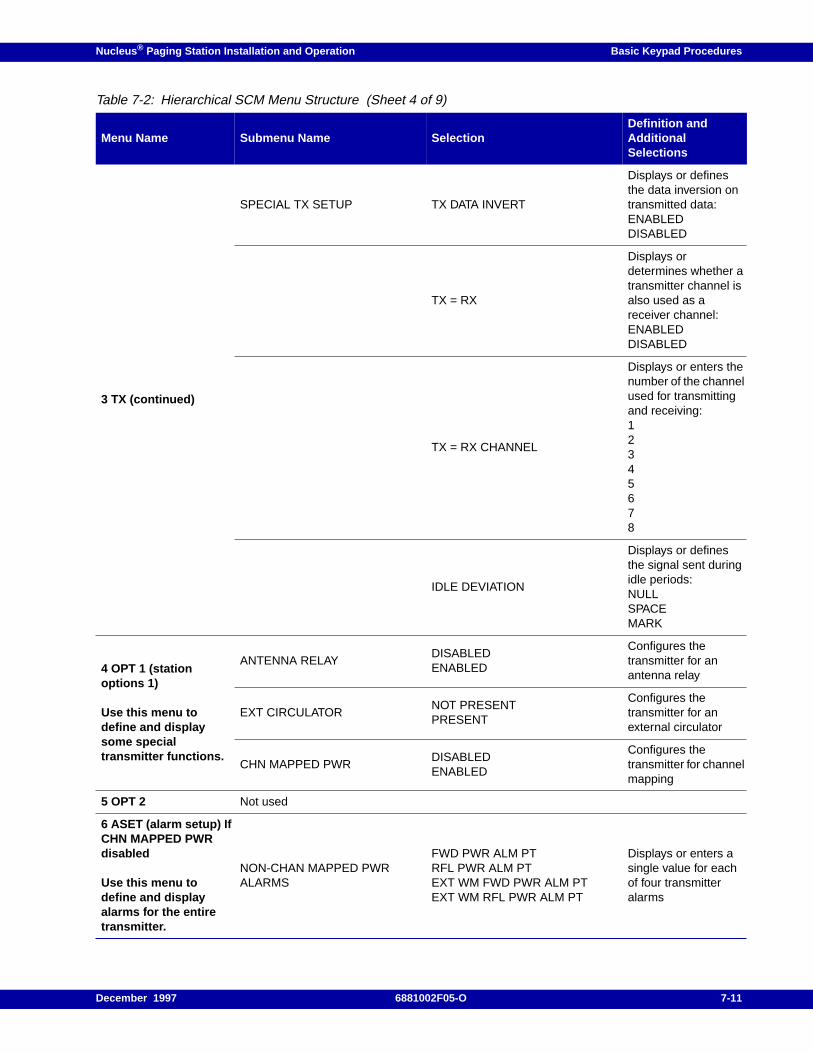
Nucleus ® Paging Station Installation and Operation Basic Keypad Procedures
3 TX (continued)
SPECIAL TX SETUP TX DATA INVERT
Displays or definesthe data inversion ontransmitted data:ENABLEDDISABLED
TX = RX
Displays ordetermines whether atransmitter channel isalso used as areceiver channel:ENABLEDDISABLED
TX = RX CHANNEL
Displays or enters thenumber of the channelused for transmittingand receiving:12345678
IDLE DEVIATION
Displays or definesthe signal sent duringidle periods:NULLSPACEMARK
4 OPT 1 (stationoptions 1)
Use this menu todefine and displaysome specialtransmitter functions.
ANTENNA RELAYDISABLEDENABLED
Configures thetransmitter for anantenna relay
EXT CIRCULATORNOT PRESENTPRESENT
Configures thetransmitter for anexternal circulator
CHN MAPPED PWRDISABLEDENABLED
Configures thetransmitter for channelmapping
5 OPT 2 Not used
6 ASET (alarm setup) IfCHN MAPPED PWRdisabled
Use this menu todefine and displayalarms for the entiretransmitter.
NON-CHAN MAPPED PWRALARMS
FWD PWR ALM PTRFL PWR ALM PTEXT WM FWD PWR ALM PTEXT WM RFL PWR ALM PT
Displays or enters asingle value for eachof four transmitteralarms
Table 7-2: Hierarchical SCM Menu Structure (Sheet 4 of 9)
Menu Name Submenu Name SelectionDefinition andAdditionalSelections
December 1997 6881002F05-O 7-11
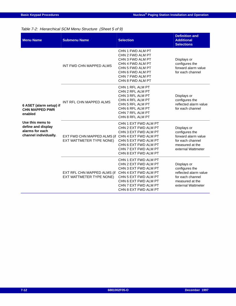
Basic Keypad Procedures Nucleus ® Paging Station Installation and Operation
6 ASET (alarm setup) ifCHN MAPPED PWRenabled
Use this menu todefine and displayalarms for eachchannel individually.
INT FWD CHN MAPPED ALMS
CHN 1 FWD ALM PTCHN 2 FWD ALM PTCHN 3 FWD ALM PTCHN 4 FWD ALM PTCHN 5 FWD ALM PTCHN 6 FWD ALM PTCHN 7 FWD ALM PTCHN 8 FWD ALM PT
Displays orconfigures theforward alarm valuefor each channel
INT RFL CHN MAPPED ALMS
CHN 1 RFL ALM PTCHN 2 RFL ALM PTCHN 3 RFL ALM PTCHN 4 RFL ALM PTCHN 5 RFL ALM PTCHN 6 RFL ALM PTCHN 7 RFL ALM PTCHN 8 RFL ALM PT
Displays orconfigures thereflected alarm valuefor each channel
EXT FWD CHN MAPPED ALMS (ifEXT WATTMETER TYPE NONE)
CHN 1 EXT FWD ALM PTCHN 2 EXT FWD ALM PTCHN 3 EXT FWD ALM PTCHN 4 EXT FWD ALM PTCHN 5 EXT FWD ALM PTCHN 6 EXT FWD ALM PTCHN 7 EXT FWD ALM PTCHN 8 EXT FWD ALM PT
Displays orconfigures theforward alarm valuefor each channelmeasured at theexternal Wattmeter
EXT RFL CHN MAPPED ALMS (ifEXT WATTMETER TYPE NONE)
CHN 1 EXT FWD ALM PTCHN 2 EXT FWD ALM PTCHN 3 EXT FWD ALM PTCHN 4 EXT FWD ALM PTCHN 5 EXT FWD ALM PTCHN 6 EXT FWD ALM PTCHN 7 EXT FWD ALM PTCHN 8 EXT FWD ALM PT
Displays orconfigures thereflected alarm valuefor each channelmeasured at theexternal Wattmeter
Table 7-2: Hierarchical SCM Menu Structure (Sheet 5 of 9)
Menu Name Submenu Name SelectionDefinition andAdditionalSelections
7-12 6881002F05-O December 1997
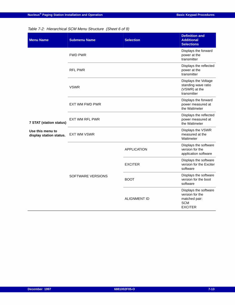
Nucleus ® Paging Station Installation and Operation Basic Keypad Procedures
7 STAT (station status)
Use this menu todisplay station status.
FWD PWRDisplays the forwardpower at thetransmitter
RFL PWRDisplays the reflectedpower at thetransmitter
VSWR
Displays the Voltagestanding wave ratio(VSWR) at thetransmitter
EXT WM FWD PWRDisplays the forwardpower measured atthe Wattmeter
EXT WM RFL PWRDisplays the reflectedpower measured atthe Wattmeter
EXT WM VSWRDisplays the VSWRmeasured at theWattmeter
SOFTWARE VERSIONS
APPLICATIONDisplays the softwareversion for theapplication software
EXCITERDisplays the softwareversion for the Excitersoftware
BOOTDisplays the softwareversion for the bootsoftware
ALIGNMENT ID
Displays the softwareversion for thematched pair:SCMEXCITER
Table 7-2: Hierarchical SCM Menu Structure (Sheet 6 of 9)
Menu Name Submenu Name SelectionDefinition andAdditionalSelections
December 1997 6881002F05-O 7-13
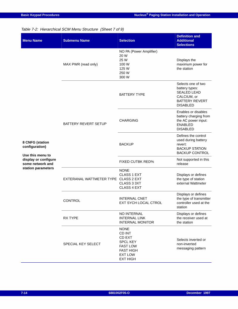
Basic Keypad Procedures Nucleus ® Paging Station Installation and Operation
8 CNFG (stationconfiguration)
Use this menu todisplay or configuresome network andstation parameters
MAX PWR (read only)
NO PA (Power Amplifier)20 W25 W100 W125 W250 W300 W
Displays themaximum power forthe station
BATTERY REVERT SETUP
BATTERY TYPE
Selects one of twobattery types:SEALED LEADCALCIUM, orBATTERY REVERTDISABLED
CHARGING
Enables or disablesbattery charging fromthe AC power input:ENABLEDDISABLED
BACKUP
Defines the controlused during batteryrevert:BACKUP STATIONBACKUP CONTROL
FIXED CUTBK RED%Not supported in thisrelease
EXTERANAL WATTMETER TYPE
NONECLASS 1 EXTCLASS 2 EXTCLASS 3 3XTCLASS 4 EXT
Displays or definesthe type of stationexternal Wattmeter
CONTROLINTERNAL CNETEXT SYCH LOCAL CTROL
Displays or definesthe type of transmittercontroller used at thestation
RX TYPENO INTERNALINTERNAL LINKINTERNAL MONITOR
Displays or definesthe receiver used atthe station
SPECIAL KEY SELECT
NONECD INTCD EXTSPCL KEYFAST LOWFAST HIGHEXT LOWEXT HIGH
Selects inverted ornon-invertedmessaging pattern
Table 7-2: Hierarchical SCM Menu Structure (Sheet 7 of 9)
Menu Name Submenu Name SelectionDefinition andAdditionalSelections
7-14 6881002F05-O December 1997
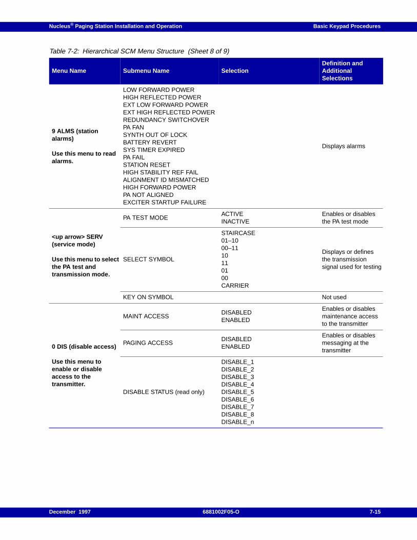
Nucleus ® Paging Station Installation and Operation Basic Keypad Procedures
9 ALMS (stationalarms)
Use this menu to readalarms.
LOW FORWARD POWERHIGH REFLECTED POWEREXT LOW FORWARD POWEREXT HIGH REFLECTED POWERREDUNDANCY SWITCHOVERPA FANSYNTH OUT OF LOCKBATTERY REVERTSYS TIMER EXPIREDPA FAILSTATION RESETHIGH STABILITY REF FAILALIGNMENT ID MISMATCHEDHIGH FORWARD POWERPA NOT ALIGNEDEXCITER STARTUP FAILURE
Displays alarms
<up arrow> SERV(service mode)
Use this menu to selectthe PA test andtransmission mode.
PA TEST MODEACTIVEINACTIVE
Enables or disablesthe PA test mode
SELECT SYMBOL
STAIRCASE01–1000–1110110100CARRIER
Displays or definesthe transmissionsignal used for testing
KEY ON SYMBOL Not used
0 DIS (disable access)
Use this menu toenable or disableaccess to thetransmitter.
MAINT ACCESSDISABLEDENABLED
Enables or disablesmaintenance accessto the transmitter
PAGING ACCESSDISABLEDENABLED
Enables or disablesmessaging at thetransmitter
DISABLE STATUS (read only)
DISABLE_1DISABLE_2DISABLE_3DISABLE_4DISABLE_5DISABLE_6DISABLE_7DISABLE_8DISABLE_n
Table 7-2: Hierarchical SCM Menu Structure (Sheet 8 of 9)
Menu Name Submenu Name SelectionDefinition andAdditionalSelections
December 1997 6881002F05-O 7-15
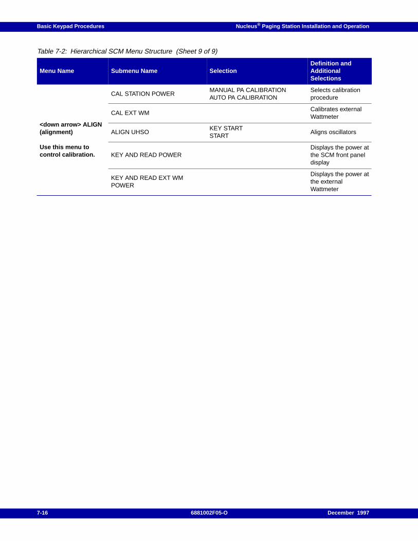
Basic Keypad Procedures Nucleus ® Paging Station Installation and Operation
<down arrow> ALIGN(alignment)
Use this menu tocontrol calibration.
CAL STATION POWERMANUAL PA CALIBRATIONAUTO PA CALIBRATION
Selects calibrationprocedure
CAL EXT WMCalibrates externalWattmeter
ALIGN UHSOKEY STARTSTART
Aligns oscillators
KEY AND READ POWERDisplays the power atthe SCM front paneldisplay
KEY AND READ EXT WMPOWER
Displays the power atthe externalWattmeter
Table 7-2: Hierarchical SCM Menu Structure (Sheet 9 of 9)
Menu Name Submenu Name SelectionDefinition andAdditionalSelections
7-16 6881002F05-O December 1997
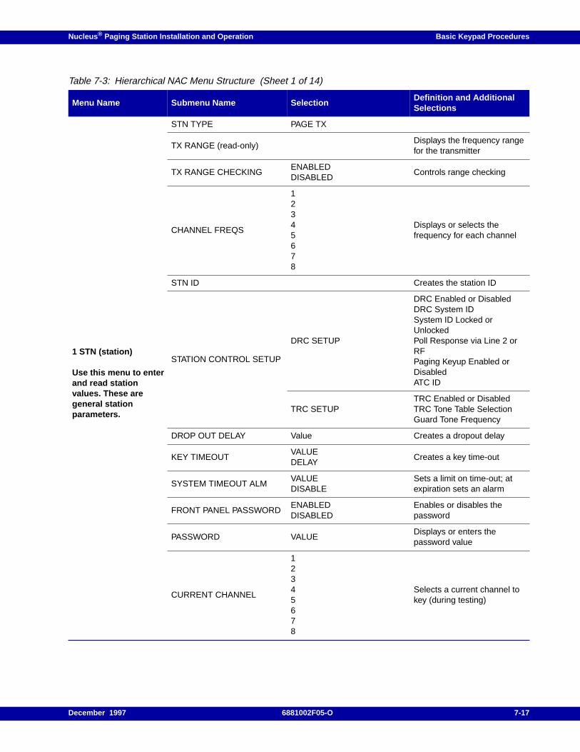
Nucleus ® Paging Station Installation and Operation Basic Keypad Procedures
Table 7-3: Hierarchical NAC Menu Structure (Sheet 1 of 14)
Menu Name Submenu Name SelectionDefinition and AdditionalSelections
1 STN (station)
Use this menu to enterand read stationvalues. These aregeneral stationparameters.
STN TYPE PAGE TX
TX RANGE (read-only)Displays the frequency rangefor the transmitter
TX RANGE CHECKINGENABLEDDISABLED
Controls range checking
CHANNEL FREQS
12345678
Displays or selects thefrequency for each channel
STN ID Creates the station ID
STATION CONTROL SETUP
DRC SETUP
DRC Enabled or DisabledDRC System IDSystem ID Locked orUnlockedPoll Response via Line 2 orRFPaging Keyup Enabled orDisabledATC ID
TRC SETUPTRC Enabled or DisabledTRC Tone Table SelectionGuard Tone Frequency
DROP OUT DELAY Value Creates a dropout delay
KEY TIMEOUTVALUEDELAY
Creates a key time-out
SYSTEM TIMEOUT ALMVALUEDISABLE
Sets a limit on time-out; atexpiration sets an alarm
FRONT PANEL PASSWORDENABLEDDISABLED
Enables or disables thepassword
PASSWORD VALUEDisplays or enters thepassword value
CURRENT CHANNEL
12345678
Selects a current channel tokey (during testing)
December 1997 6881002F05-O 7-17
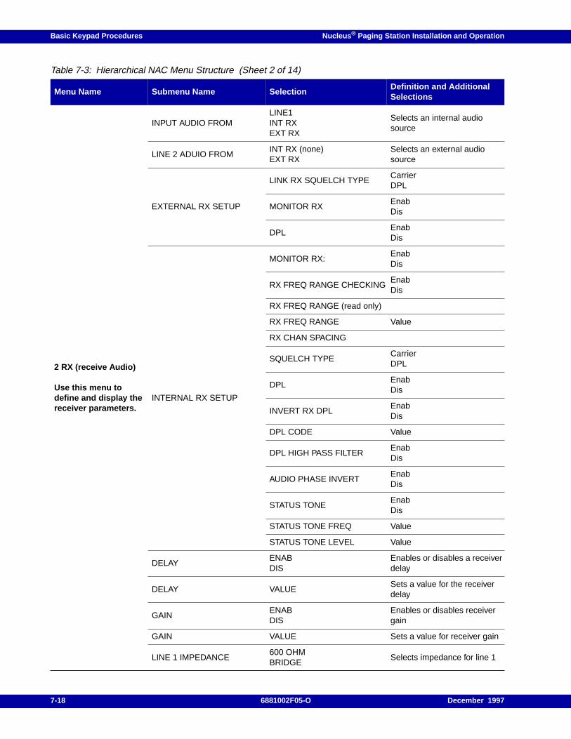
Basic Keypad Procedures Nucleus ® Paging Station Installation and Operation
2 RX (receive Audio)
Use this menu todefine and display thereceiver parameters.
INPUT AUDIO FROMLINE1INT RXEXT RX
Selects an internal audiosource
LINE 2 ADUIO FROMINT RX (none)EXT RX
Selects an external audiosource
EXTERNAL RX SETUP
LINK RX SQUELCH TYPECarrierDPL
MONITOR RXEnabDis
DPLEnabDis
INTERNAL RX SETUP
MONITOR RX:EnabDis
RX FREQ RANGE CHECKINGEnabDis
RX FREQ RANGE (read only)
RX FREQ RANGE Value
RX CHAN SPACING
SQUELCH TYPECarrierDPL
DPLEnabDis
INVERT RX DPLEnabDis
DPL CODE Value
DPL HIGH PASS FILTEREnabDis
AUDIO PHASE INVERTEnabDis
STATUS TONEEnabDis
STATUS TONE FREQ Value
STATUS TONE LEVEL Value
DELAYENABDIS
Enables or disables a receiverdelay
DELAY VALUESets a value for the receiverdelay
GAINENABDIS
Enables or disables receivergain
GAIN VALUE Sets a value for receiver gain
LINE 1 IMPEDANCE600 OHMBRIDGE
Selects impedance for line 1
Table 7-3: Hierarchical NAC Menu Structure (Sheet 2 of 14)
Menu Name Submenu Name SelectionDefinition and AdditionalSelections
7-18 6881002F05-O December 1997
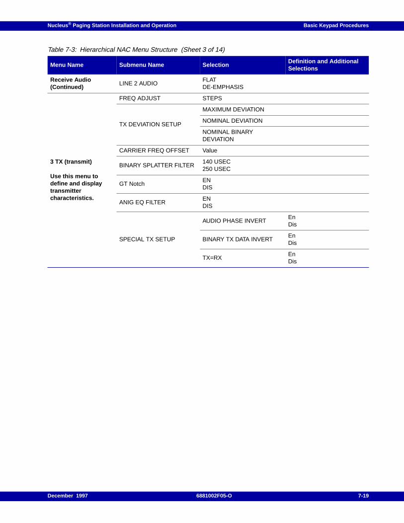
Nucleus ® Paging Station Installation and Operation Basic Keypad Procedures
Receive Audio(Continued)
LINE 2 AUDIOFLATDE-EMPHASIS
3 TX (transmit)
Use this menu todefine and displaytransmittercharacteristics.
FREQ ADJUST STEPS
TX DEVIATION SETUP
MAXIMUM DEVIATION
NOMINAL DEVIATION
NOMINAL BINARYDEVIATION
CARRIER FREQ OFFSET Value
BINARY SPLATTER FILTER140 USEC250 USEC
GT NotchENDIS
ANIG EQ FILTERENDIS
SPECIAL TX SETUP
AUDIO PHASE INVERTEnDis
BINARY TX DATA INVERTEnDis
TX=RXEnDis
Table 7-3: Hierarchical NAC Menu Structure (Sheet 3 of 14)
Menu Name Submenu Name SelectionDefinition and AdditionalSelections
December 1997 6881002F05-O 7-19
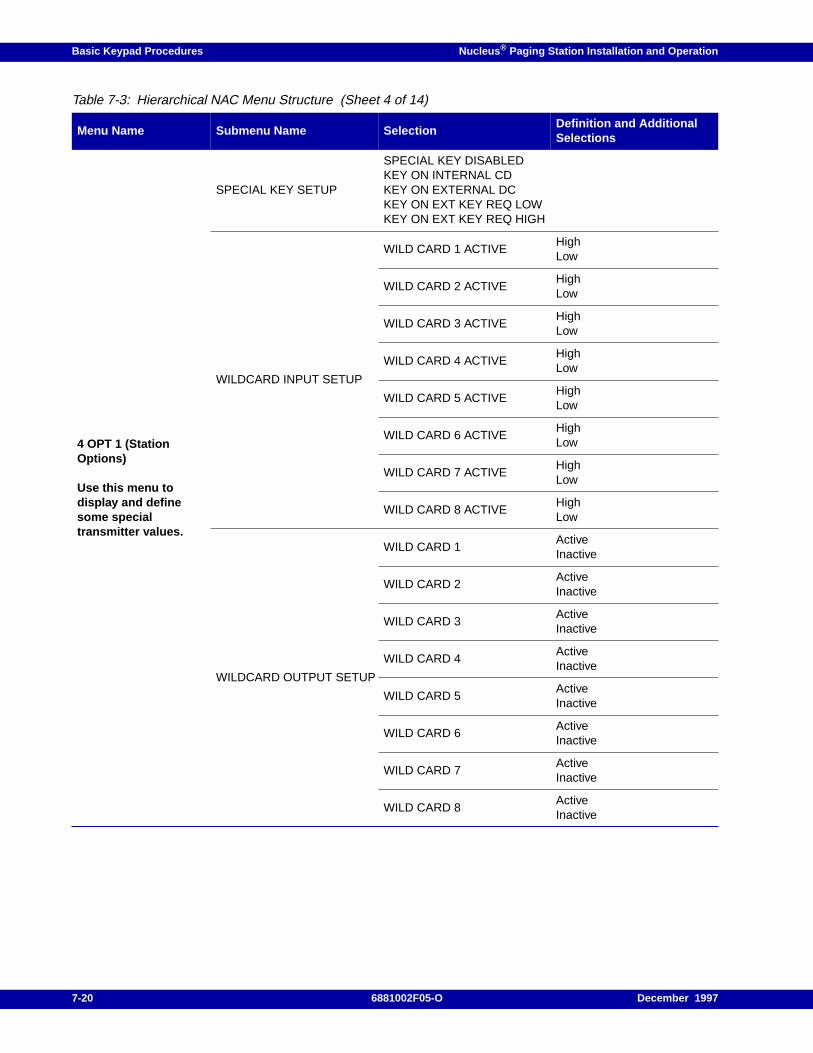
Basic Keypad Procedures Nucleus ® Paging Station Installation and Operation
4 OPT 1 (StationOptions)
Use this menu todisplay and definesome specialtransmitter values.
SPECIAL KEY SETUP
SPECIAL KEY DISABLEDKEY ON INTERNAL CDKEY ON EXTERNAL DCKEY ON EXT KEY REQ LOWKEY ON EXT KEY REQ HIGH
WILDCARD INPUT SETUP
WILD CARD 1 ACTIVEHighLow
WILD CARD 2 ACTIVEHighLow
WILD CARD 3 ACTIVEHighLow
WILD CARD 4 ACTIVEHighLow
WILD CARD 5 ACTIVEHighLow
WILD CARD 6 ACTIVEHighLow
WILD CARD 7 ACTIVEHighLow
WILD CARD 8 ACTIVEHighLow
WILDCARD OUTPUT SETUP
WILD CARD 1ActiveInactive
WILD CARD 2ActiveInactive
WILD CARD 3ActiveInactive
WILD CARD 4ActiveInactive
WILD CARD 5ActiveInactive
WILD CARD 6ActiveInactive
WILD CARD 7ActiveInactive
WILD CARD 8ActiveInactive
Table 7-3: Hierarchical NAC Menu Structure (Sheet 4 of 14)
Menu Name Submenu Name SelectionDefinition and AdditionalSelections
7-20 6881002F05-O December 1997
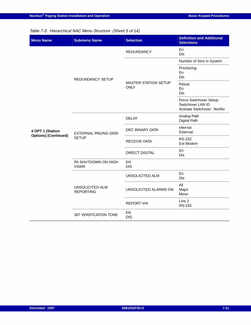
Nucleus ® Paging Station Installation and Operation Basic Keypad Procedures
4 OPT 1 (StationOptions) (Continued)
REDUNDANCY SETUP
REDUNDANCYEnDis
MASTER STATION SETUPONLY
Number of Stns in System
Prioritizing:EnDis
Keyup:EnDis
Force Switchover Setup:Switchover LAN IDActivate Switchover: Yes/No
EXTERNAL PAGING DATASETUP
DELAYAnalog PathDigital Path
DRC BINARY DATAInternalExternal;
RECEIVE DATARS-232Ext Modem
DIRECT DIGITALEnDis
PA SHUTDOWN ON HIGHVSWR
ENDIS
UNSOLICITED ALMREPORTING
UNSOLICITED ALMEnDis
UNSOLICITED ALARMS ONAllMajorMinor
REPORT VIALine 2RS-232
387 VERIFICATION TONEENDIS
Table 7-3: Hierarchical NAC Menu Structure (Sheet 5 of 14)
Menu Name Submenu Name SelectionDefinition and AdditionalSelections
December 1997 6881002F05-O 7-21
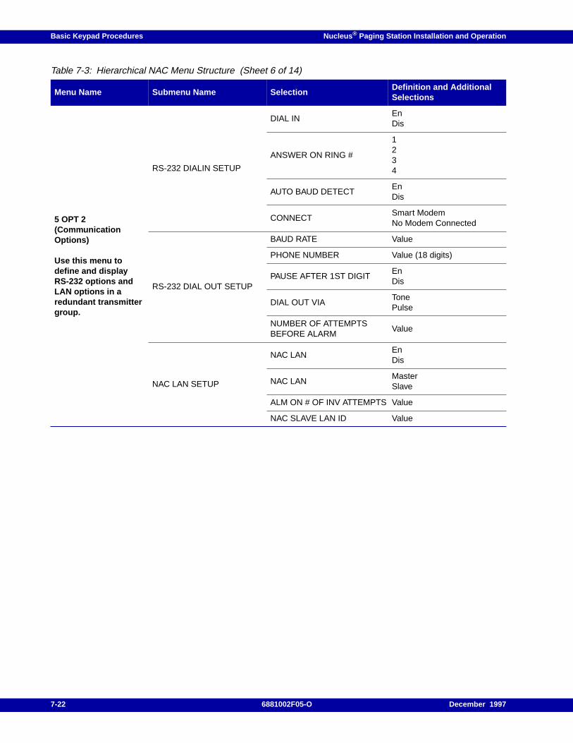
Basic Keypad Procedures Nucleus ® Paging Station Installation and Operation
5 OPT 2(CommunicationOptions)
Use this menu todefine and displayRS-232 options andLAN options in aredundant transmittergroup.
RS-232 DIALIN SETUP
DIAL INEnDis
ANSWER ON RING #
1234
AUTO BAUD DETECTEnDis
CONNECTSmart ModemNo Modem Connected
RS-232 DIAL OUT SETUP
BAUD RATE Value
PHONE NUMBER Value (18 digits)
PAUSE AFTER 1ST DIGITEnDis
DIAL OUT VIATonePulse
NUMBER OF ATTEMPTSBEFORE ALARM
Value
NAC LAN SETUP
NAC LANEnDis
NAC LANMasterSlave
ALM ON # OF INV ATTEMPTS Value
NAC SLAVE LAN ID Value
Table 7-3: Hierarchical NAC Menu Structure (Sheet 6 of 14)
Menu Name Submenu Name SelectionDefinition and AdditionalSelections
7-22 6881002F05-O December 1997
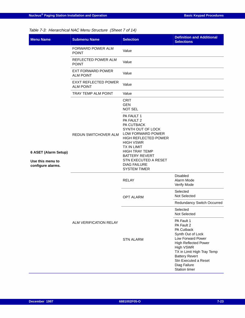
Nucleus ® Paging Station Installation and Operation Basic Keypad Procedures
6 ASET (Alarm Setup)
Use this menu toconfigure alarms.
FORWARD POWER ALMPOINT
Value
REFLECTED POWER ALMPOINT
Value
EXT FORWARD POWERALM POINT
Value
EXXT REFLECTED POWERALM POINT
Value
TRAY TEMP ALM POINT Value
REDUN SWITCHOVER ALM
CRITGENNOT SEL
PA FAULT 1PA FAULT 2PA CUTBACKSYNTH OUT OF LOCKLOW FORWARD POWERHIGH REFLECTED POWERHIGH VSWRTX IN LIMITHIGH TRAY TEMPBATTERY REVERTSTN EXECUTED A RESETDIAG FAILURESYSTEM TIMER
ALM VERIFICATION RELAY
RELAYDisabledAlarm ModeVerify Mode
OPT ALARM
SelectedNot Selected
Redundancy Switch Occurred
STN ALARM
SelectedNot Selected
PA Fault 1PA Fault 2PA CutbackSynth Out of LockLow Forward PowerHigh Reflected PowerHigh VSWRTX in Limit High Tray TempBattery RevertStn Executed a ResetDiag FailureStation timer
Table 7-3: Hierarchical NAC Menu Structure (Sheet 7 of 14)
Menu Name Submenu Name SelectionDefinition and AdditionalSelections
December 1997 6881002F05-O 7-23
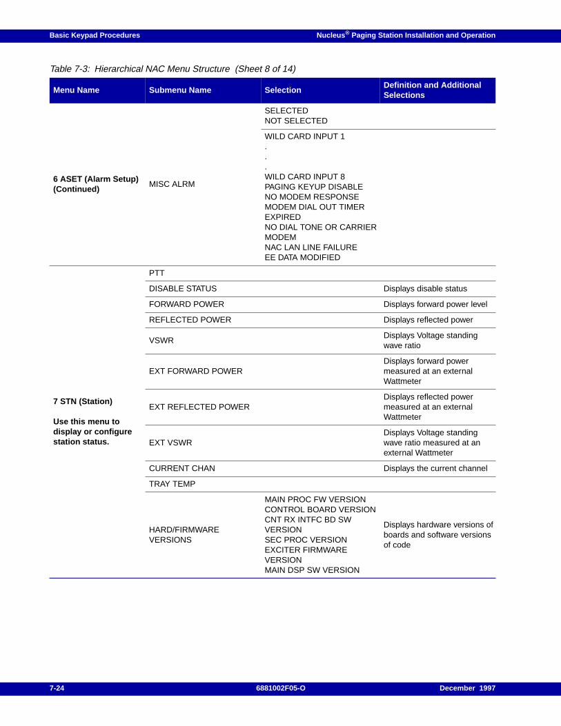
Basic Keypad Procedures Nucleus ® Paging Station Installation and Operation
6 ASET (Alarm Setup)(Continued)
MISC ALRM
SELECTEDNOT SELECTED
WILD CARD INPUT 1...WILD CARD INPUT 8PAGING KEYUP DISABLENO MODEM RESPONSEMODEM DIAL OUT TIMEREXPIREDNO DIAL TONE OR CARRIERMODEMNAC LAN LINE FAILUREEE DATA MODIFIED
7 STN (Station)
Use this menu todisplay or configurestation status.
PTT
DISABLE STATUS Displays disable status
FORWARD POWER Displays forward power level
REFLECTED POWER Displays reflected power
VSWRDisplays Voltage standingwave ratio
EXT FORWARD POWERDisplays forward powermeasured at an externalWattmeter
EXT REFLECTED POWERDisplays reflected powermeasured at an externalWattmeter
EXT VSWRDisplays Voltage standingwave ratio measured at anexternal Wattmeter
CURRENT CHAN Displays the current channel
TRAY TEMP
HARD/FIRMWAREVERSIONS
MAIN PROC FW VERSIONCONTROL BOARD VERSIONCNT RX INTFC BD SWVERSIONSEC PROC VERSIONEXCITER FIRMWAREVERSIONMAIN DSP SW VERSION
Displays hardware versions ofboards and software versionsof code
Table 7-3: Hierarchical NAC Menu Structure (Sheet 8 of 14)
Menu Name Submenu Name SelectionDefinition and AdditionalSelections
7-24 6881002F05-O December 1997
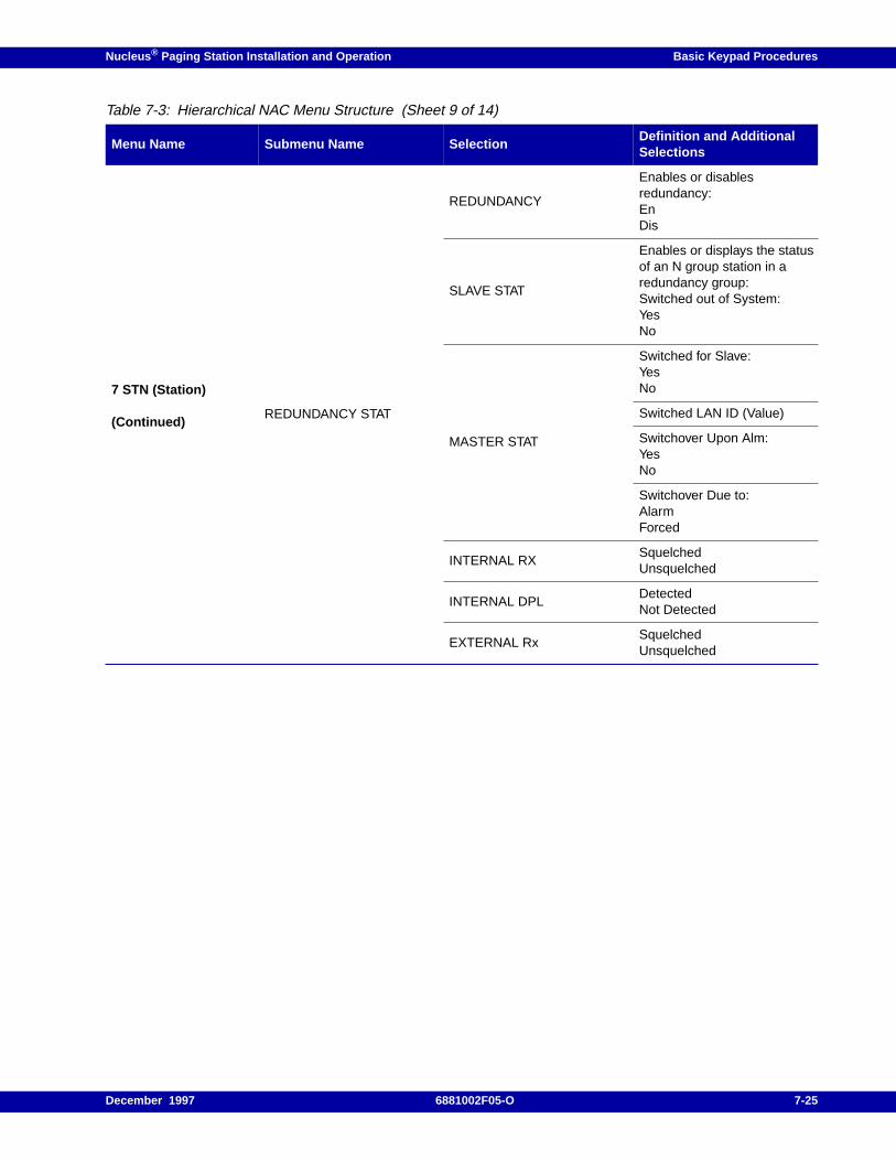
Nucleus ® Paging Station Installation and Operation Basic Keypad Procedures
7 STN (Station)
(Continued)REDUNDANCY STAT
REDUNDANCY
Enables or disablesredundancy:EnDis
SLAVE STAT
Enables or displays the statusof an N group station in aredundancy group:Switched out of System:YesNo
MASTER STAT
Switched for Slave:YesNo
Switched LAN ID (Value)
Switchover Upon Alm:YesNo
Switchover Due to:AlarmForced
INTERNAL RXSquelchedUnsquelched
INTERNAL DPLDetectedNot Detected
EXTERNAL RxSquelchedUnsquelched
Table 7-3: Hierarchical NAC Menu Structure (Sheet 9 of 14)
Menu Name Submenu Name SelectionDefinition and AdditionalSelections
December 1997 6881002F05-O 7-25
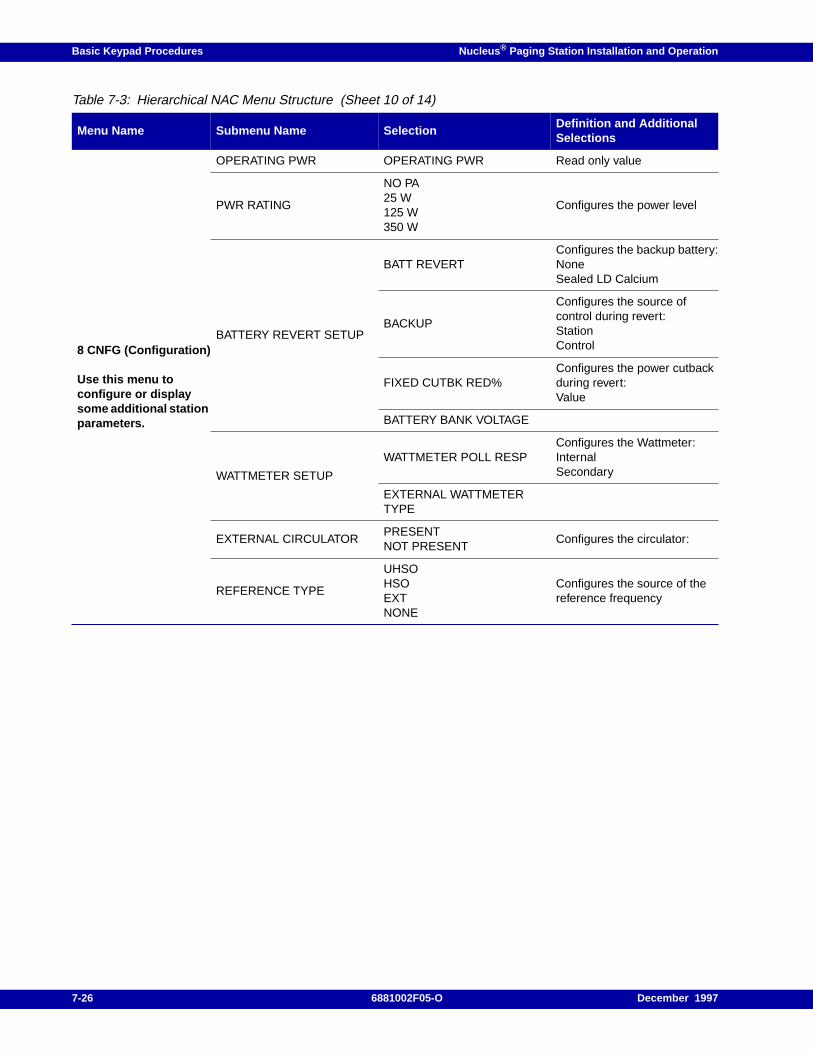
Basic Keypad Procedures Nucleus ® Paging Station Installation and Operation
8 CNFG (Configuration)
Use this menu toconfigure or displaysome additional stationparameters.
OPERATING PWR OPERATING PWR Read only value
PWR RATING
NO PA25 W125 W350 W
Configures the power level
BATTERY REVERT SETUP
BATT REVERTConfigures the backup battery:NoneSealed LD Calcium
BACKUP
Configures the source ofcontrol during revert:StationControl
FIXED CUTBK RED%Configures the power cutbackduring revert:Value
BATTERY BANK VOLTAGE
WATTMETER SETUP
WATTMETER POLL RESPConfigures the Wattmeter:InternalSecondary
EXTERNAL WATTMETERTYPE
EXTERNAL CIRCULATORPRESENTNOT PRESENT
Configures the circulator:
REFERENCE TYPE
UHSOHSOEXTNONE
Configures the source of thereference frequency
Table 7-3: Hierarchical NAC Menu Structure (Sheet 10 of 14)
Menu Name Submenu Name SelectionDefinition and AdditionalSelections
7-26 6881002F05-O December 1997
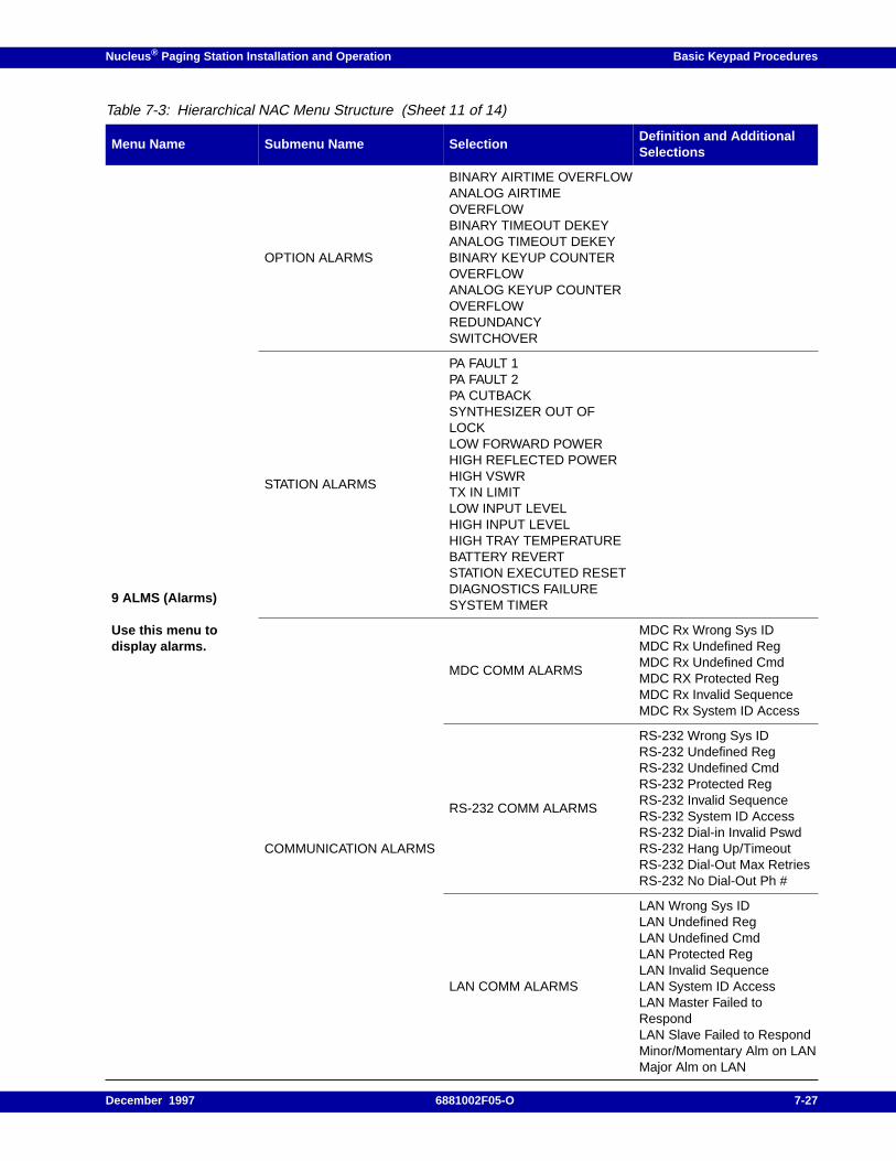
Nucleus ® Paging Station Installation and Operation Basic Keypad Procedures
9 ALMS (Alarms)
Use this menu todisplay alarms.
OPTION ALARMS
BINARY AIRTIME OVERFLOWANALOG AIRTIMEOVERFLOWBINARY TIMEOUT DEKEYANALOG TIMEOUT DEKEYBINARY KEYUP COUNTEROVERFLOWANALOG KEYUP COUNTEROVERFLOWREDUNDANCYSWITCHOVER
STATION ALARMS
PA FAULT 1PA FAULT 2PA CUTBACKSYNTHESIZER OUT OFLOCKLOW FORWARD POWERHIGH REFLECTED POWERHIGH VSWRTX IN LIMITLOW INPUT LEVELHIGH INPUT LEVELHIGH TRAY TEMPERATUREBATTERY REVERTSTATION EXECUTED RESETDIAGNOSTICS FAILURESYSTEM TIMER
COMMUNICATION ALARMS
MDC COMM ALARMS
MDC Rx Wrong Sys IDMDC Rx Undefined RegMDC Rx Undefined CmdMDC RX Protected RegMDC Rx Invalid SequenceMDC Rx System ID Access
RS-232 COMM ALARMS
RS-232 Wrong Sys IDRS-232 Undefined RegRS-232 Undefined CmdRS-232 Protected RegRS-232 Invalid SequenceRS-232 System ID AccessRS-232 Dial-in Invalid PswdRS-232 Hang Up/TimeoutRS-232 Dial-Out Max RetriesRS-232 No Dial-Out Ph #
LAN COMM ALARMS
LAN Wrong Sys IDLAN Undefined RegLAN Undefined CmdLAN Protected RegLAN Invalid SequenceLAN System ID AccessLAN Master Failed toRespondLAN Slave Failed to RespondMinor/Momentary Alm on LAN
Table 7-3: Hierarchical NAC Menu Structure (Sheet 11 of 14)
Menu Name Submenu Name SelectionDefinition and AdditionalSelections
December 1997 6881002F05-O 7-27
Major Alm on LAN
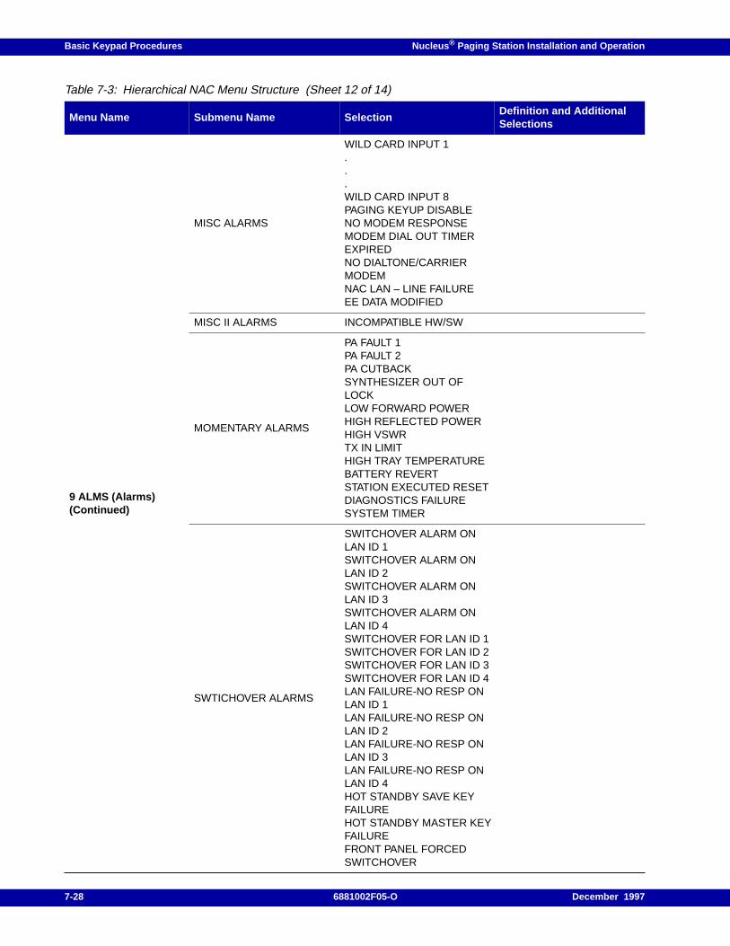
Basic Keypad Procedures Nucleus ® Paging Station Installation and Operation
9 ALMS (Alarms)(Continued)
MISC ALARMS
WILD CARD INPUT 1...WILD CARD INPUT 8PAGING KEYUP DISABLENO MODEM RESPONSEMODEM DIAL OUT TIMEREXPIREDNO DIALTONE/CARRIERMODEMNAC LAN – LINE FAILUREEE DATA MODIFIED
MISC II ALARMS INCOMPATIBLE HW/SW
MOMENTARY ALARMS
PA FAULT 1PA FAULT 2PA CUTBACKSYNTHESIZER OUT OFLOCKLOW FORWARD POWERHIGH REFLECTED POWERHIGH VSWRTX IN LIMITHIGH TRAY TEMPERATUREBATTERY REVERTSTATION EXECUTED RESETDIAGNOSTICS FAILURESYSTEM TIMER
SWTICHOVER ALARMS
SWITCHOVER ALARM ONLAN ID 1SWITCHOVER ALARM ONLAN ID 2SWITCHOVER ALARM ONLAN ID 3SWITCHOVER ALARM ONLAN ID 4SWITCHOVER FOR LAN ID 1SWITCHOVER FOR LAN ID 2SWITCHOVER FOR LAN ID 3SWITCHOVER FOR LAN ID 4LAN FAILURE-NO RESP ONLAN ID 1LAN FAILURE-NO RESP ONLAN ID 2LAN FAILURE-NO RESP ONLAN ID 3LAN FAILURE-NO RESP ONLAN ID 4HOT STANDBY SAVE KEYFAILUREHOT STANDBY MASTER KEYFAILUREFRONT PANEL FORCEDSWITCHOVER
Table 7-3: Hierarchical NAC Menu Structure (Sheet 12 of 14)
Menu Name Submenu Name SelectionDefinition and AdditionalSelections
7-28 6881002F05-O December 1997
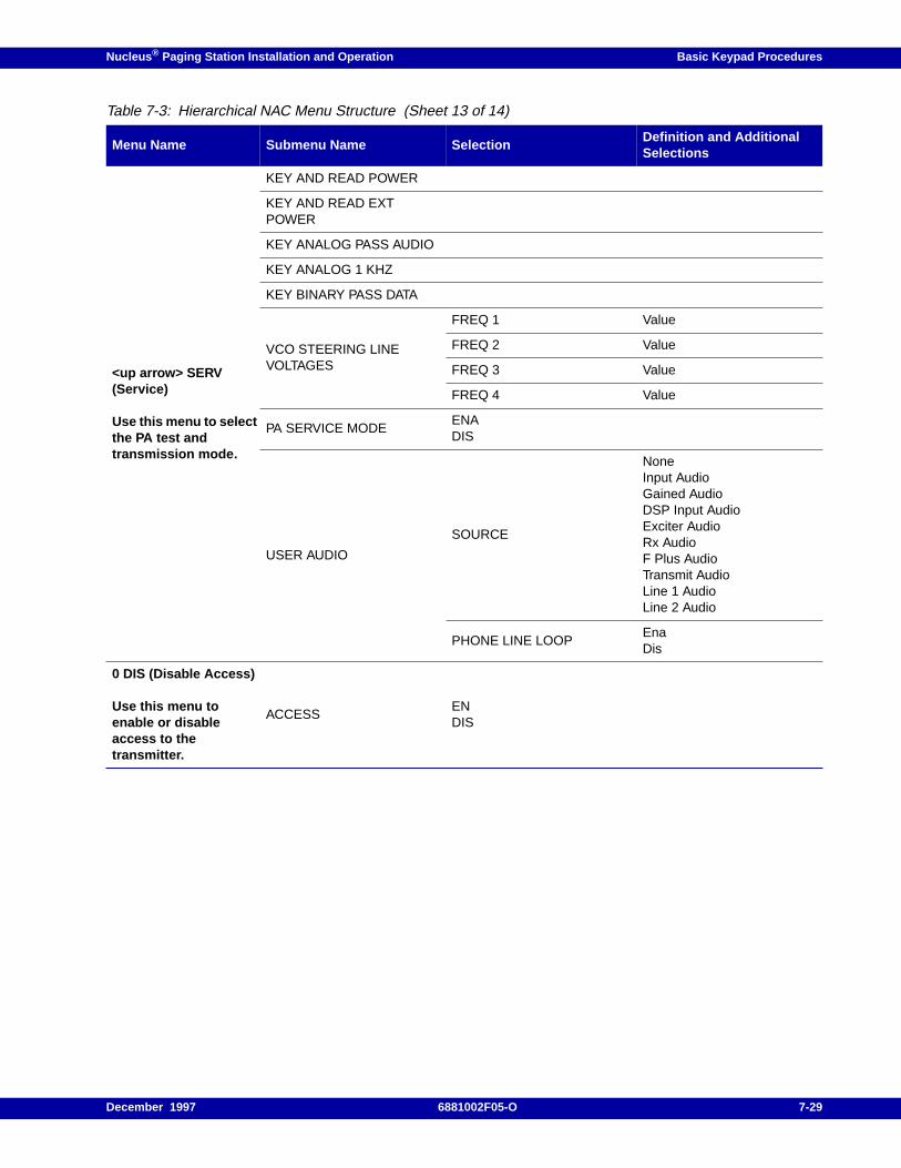
Nucleus ® Paging Station Installation and Operation Basic Keypad Procedures
<up arrow> SERV(Service)
Use this menu to selectthe PA test andtransmission mode.
KEY AND READ POWER
KEY AND READ EXTPOWER
KEY ANALOG PASS AUDIO
KEY ANALOG 1 KHZ
KEY BINARY PASS DATA
VCO STEERING LINEVOLTAGES
FREQ 1 Value
FREQ 2 Value
FREQ 3 Value
FREQ 4 Value
PA SERVICE MODEENADIS
USER AUDIO
SOURCE
NoneInput AudioGained AudioDSP Input AudioExciter AudioRx AudioF Plus AudioTransmit AudioLine 1 AudioLine 2 Audio
PHONE LINE LOOPEnaDis
0 DIS (Disable Access)
Use this menu toenable or disableaccess to thetransmitter.
ACCESSENDIS
Table 7-3: Hierarchical NAC Menu Structure (Sheet 13 of 14)
Menu Name Submenu Name SelectionDefinition and AdditionalSelections
December 1997 6881002F05-O 7-29
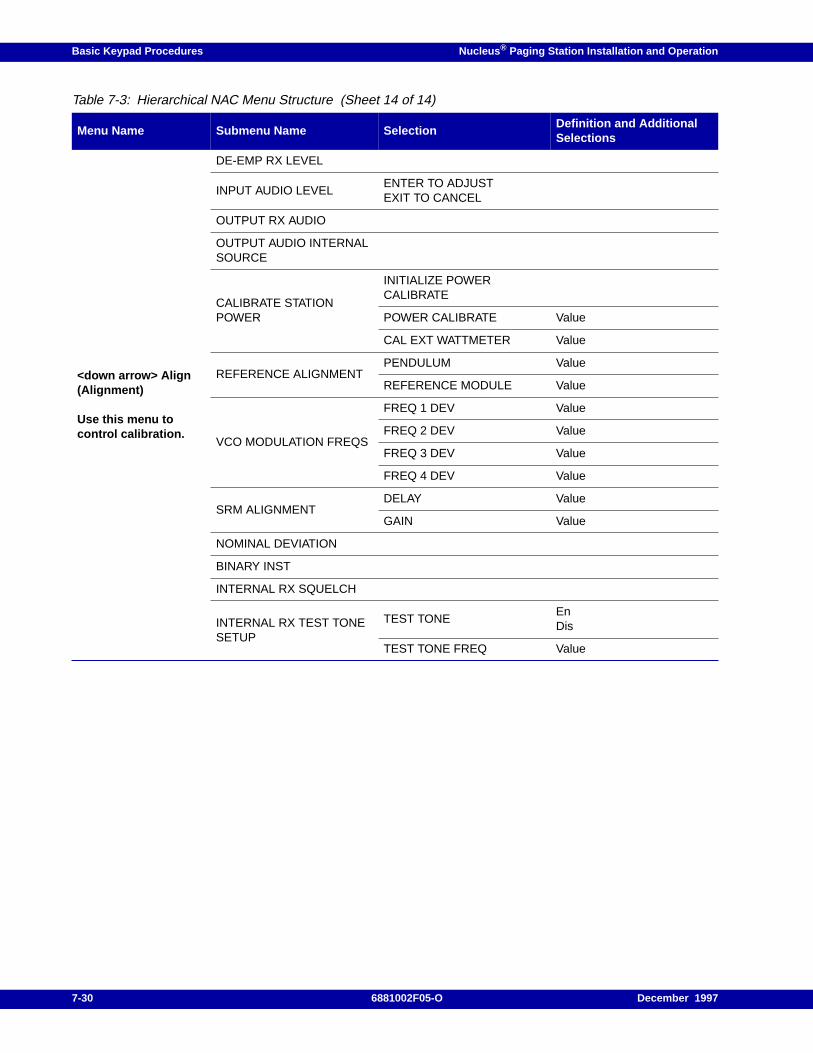
Basic Keypad Procedures Nucleus ® Paging Station Installation and Operation
<down arrow> Align(Alignment)
Use this menu tocontrol calibration.
DE-EMP RX LEVEL
INPUT AUDIO LEVELENTER TO ADJUSTEXIT TO CANCEL
OUTPUT RX AUDIO
OUTPUT AUDIO INTERNALSOURCE
CALIBRATE STATIONPOWER
INITIALIZE POWERCALIBRATE
POWER CALIBRATE Value
CAL EXT WATTMETER Value
REFERENCE ALIGNMENTPENDULUM Value
REFERENCE MODULE Value
VCO MODULATION FREQS
FREQ 1 DEV Value
FREQ 2 DEV Value
FREQ 3 DEV Value
FREQ 4 DEV Value
SRM ALIGNMENTDELAY Value
GAIN Value
NOMINAL DEVIATION
BINARY INST
INTERNAL RX SQUELCH
INTERNAL RX TEST TONESETUP
TEST TONEEnDis
TEST TONE FREQ Value
Table 7-3: Hierarchical NAC Menu Structure (Sheet 14 of 14)
Menu Name Submenu Name SelectionDefinition and AdditionalSelections
7-30 6881002F05-O December 1997
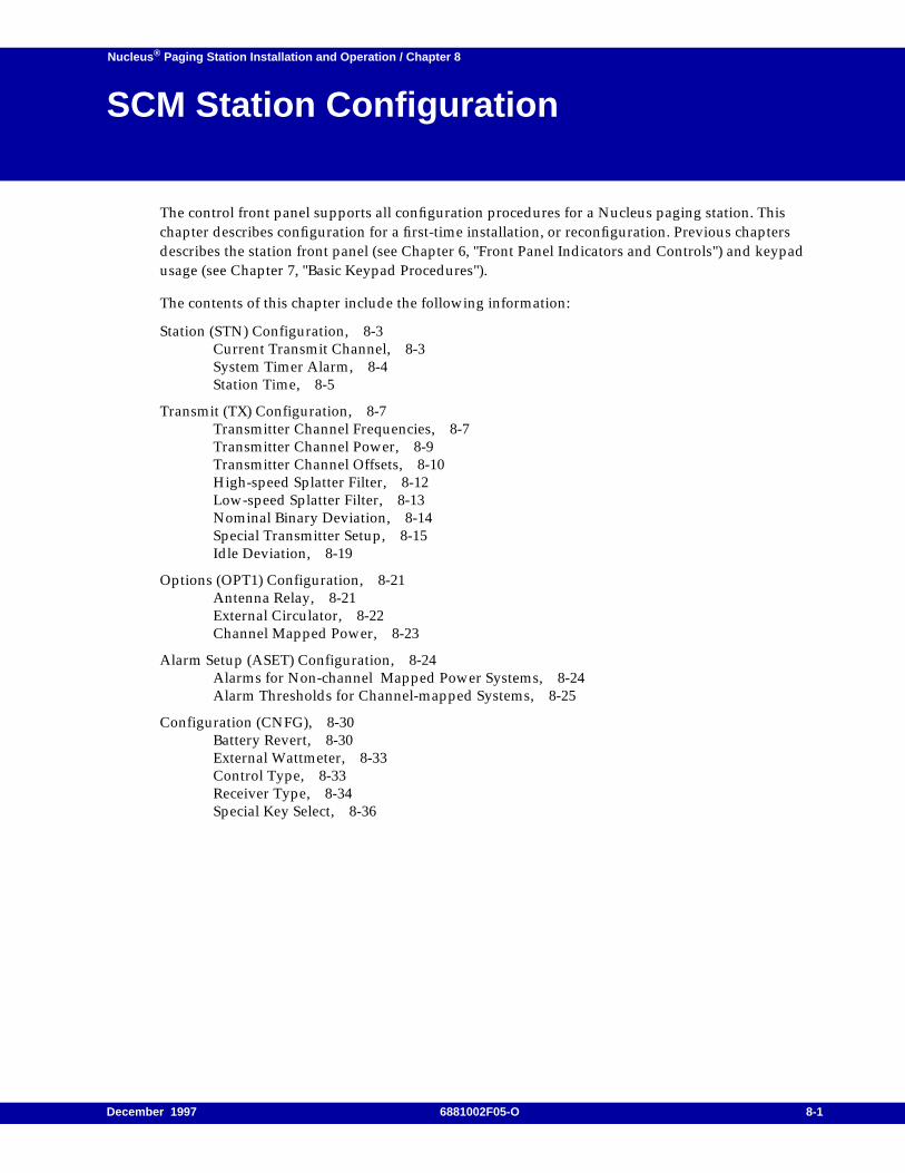
Nucleus ® Paging Station Installation and Operation / Chapter 8
SCM Station Configuration 8
The control front panel supports all configuration procedures for a Nucleus paging station. Thischapter describes configuration for a first-time installation, or reconfiguration. Previous chaptersdescribes the station front panel (see Chapter 6, "Front Panel Indicators and Controls") and keypadusage (see Chapter 7, "Basic Keypad Procedures").
The contents of this chapter include the following information:
Station (STN) Configuration, 8-3Current Transmit Channel, 8-3System Timer Alarm, 8-4Station Time, 8-5
Transmit (TX) Configuration, 8-7Transmitter Channel Frequencies, 8-7Transmitter Channel Power, 8-9Transmitter Channel Offsets, 8-10High-speed Splatter Filter, 8-12Low-speed Splatter Filter, 8-13Nominal Binary Deviation, 8-14Special Transmitter Setup, 8-15Idle Deviation, 8-19
Options (OPT1) Configuration, 8-21Antenna Relay, 8-21External Circulator, 8-22Channel Mapped Power, 8-23
Alarm Setup (ASET) Configuration, 8-24Alarms for Non-channel Mapped Power Systems, 8-24Alarm Thresholds for Channel-mapped Systems, 8-25
Configuration (CNFG), 8-30Battery Revert, 8-30External Wattmeter, 8-33Control Type, 8-33Receiver Type, 8-34Special Key Select, 8-36
December 1997 6881002F05-O 8-1

SCM Station Configuration Nucleus ® Paging Station Installation and Operation
First Time Installation
The procedures described in this chapter apply to a transmitter that is being installed for the first time,a transmitter that is being reinstalled, or a transmitter that has had extensive repairs and requiresreconfiguration. The assumed starting point is a Nucleus paging station with all defaults set. This isthe condition when Motorola ships the station from the factory, and when the station goes through areset after power down. In this condition, the Nucleus paging station disables all options.
Note: The transmitter also requires reconfiguration if you enter a new password after the station display timesout (see Chapter 7, "Basic Keypad Procedures").
This chapter describes installation, but does not describe all activities from the Station Control Module(SCM) keypad display (see Chapter 9, "SCM Station Alarms, Status, Troubleshooting, andAlignment").
This manual also provides a method or recording configuration (see Table B-1). Use the table to createa permanent record of the configuration for the Nucleus paging station.
8-2 6881002F05-O December 1997
Nucleus ® Paging Station Installation and Operation SCM Station Configuration
Station (STN) Configuration
This section describes the station configuration procedures available from the STN menu. Theseprocedures include the following:
• Setting the current transmit channel
• Setting the system timer alarm
• Setting the station time
Current Transmit Channel
This procedure configures the current transmit channel for the Nucleus paging station. Use thisprocedure to select a channel for testing.
Note: The station displays the alignment channels from this menu. However, the station automatically selectsthe alignment values during the station alignment procedure.
Use the following procedure to set the current transmit channel:
1. From the READY prompt, press <STN>.
The display briefly shows the STN menu, then displays the first submenu item:
TX FREQ RANGE: xxx-yyy
Where xxx is the lowest frequency and yyy is the highest frequency in the range.
2. Press <down arrow> to access the CURRENT TX CHN submenu.
The display shows the default or current setting:
CURRENT TX CHN: xx
Where xx is the current channel.
3. Press <ENT>.
The text flashes to show the system has entered the edit mode.
4. Press <down arrow> or <up arrow> to sequence through the channel numbers (1–8). Each numberflashes as it appears. When the display shows the appropriate channel number, press <ENT>.
The text stops flashing. The display shows the new channel number:
CURRENT TX CHN: yy
Where yy is the new channel.
Press <EXIT> to return to the READY prompt.
Note: The ALIGN 1 VCO through ALIGN 6 VCO values and the ALIGN 1 DELAY through ALIGN 4 DELAYvalues are read-only. The station calculates these values during the alignment procedure (see Chapter 9,"SCM Station Alarms, Status, Troubleshooting, and Alignment").
Continue with the paragraph, "System Timer Alarm".
December 1997 6881002F05-O 8-3
SCM Station Configuration Nucleus ® Paging Station Installation and Operation
System Timer Alarm
This procedure sets the timer alarm threshold and enables the system timer. The Nucleus paging station resetsthe system timer each time the station keys. The timer runs until the station keys and resets the timer again. If thestation fails to reset the timer before the timer expires, the station declares an alarm.
1. From the READY prompt, press <STN>.
The system accesses the Station menu. The display briefly shows the STN menu, then shows thefirst submenu item.
2. Press <down arrow> to access the SET STATION TIME submenu.
The display shows the current time:
SYS TIMER ALRM: DISABLED
This is the default value.
3. Press <ENT>.
The text flashes to show the system has entered the edit mode.
4. Press <down arrow> to sequence through the timer values:
2 MIN
15 MIN
30 MIN
60 MIN
90 MIN
120 MIN
180 MIN
DISABLED
Each value flashes as it appears.
5. When the display shows the appropriate timer value, press <ENT>.
6. The text stops flashing and the display shows the new timer value:
SYS TIMER ALRM: xxx MIN
Where xxx is the timer value in minutes.
Press <EXIT> to return to the READY prompt.
Continue with the paragraph, "Station Time".
Note: The FRONT PANEL PASSWORD submenu is described in Chapter 7, "Basic Keypad Procedures".
8-4 6881002F05-O December 1997
Nucleus ® Paging Station Installation and Operation SCM Station Configuration
Station Time
This procedure sets the Nucleus paging station date and time. The Nucleus paging station uses the date andtime to stamp error log entries. An internal battery maintains date and time for as long as 48 hours after acomplete power failure.
Use this procedure to set date and time:
1. From the READY prompt, press <STN>.
The system accesses the Station menu. The display briefly shows the STN menu, then shows thefirst submenu item.
2. Press <down arrow> to access the SET STATION TIME submenu:
SET STATION TIME
3. Press <ENT>.
The display shows the first value, the year:
YEAR: 1993
4. Press <ENT>.
The message flashes to show the system has entered the edit mode.
5. Type a new value for the year. Press <ENT>.
The display stops flashing and shows the new value:
YEAR: 1997
6. Press <down arrow> to access the month value. Press <ENT>.
The display flashes to show the system has entered the edit mode.
7. Type the new value for the month. Press <ENT>.
The display stops flashing and shows the new value:
MONTH: 2
8. Press <down arrow> to access the day value. Press <ENT>.
The display flashes to show the system has entered the edit mode.
9. Type the value for the day. Press <ENT>.
The display stops flashing and shows the new value:
DAY: 28
10. Press <down arrow> to access the hour value. Press <ENT>.
The display flashes to show the system has entered the edit mode.
December 1997 6881002F05-O 8-5
SCM Station Configuration Nucleus ® Paging Station Installation and Operation
11. Type the new value for the hour.
12. Press <ENT>.
The display stops flashing and shows the new value:
HOUR: 13
13. Press <down arrow> to access the minute value.
14. Press <ENT>.
The display flashes to show the system has entered the edit mode.
15. Type the new value for minutes.
16. Press <ENT>.
The display stops flashing and shows the new value:
MINUTE: 28
17. Press <down arrow> to access the seconds value.
18. Press <ENT>.
The display flashes to show the system has entered the edit mode.
19. Type the new value for seconds.
20. Press <ENT>.
The display stops flashing and shows the new value:
SECOND: 00
Press <EXIT> to return to the READY prompt.
Continue with the paragraph, "Transmit (TX) Configuration".
8-6 6881002F05-O December 1997
Nucleus ® Paging Station Installation and Operation SCM Station Configuration
Transmit (TX) Configuration
This section describes the transmit configuration procedures available from the TX menu. Theseprocedures include the following:
• Setting transmitter channel frequencies
• Setting transmitter channel power
• Setting transmitter channel offsets
• Setting the low-speed splatter filter
• Setting the high-speed splatter filter
• Setting the nominal binary deviation
• Setting the transmitter data
• Setting idle deviation
Transmitter Channel Frequencies
Transmit frequencies are normally set at the factory. However, the station may require a frequencychange after installation.
Note: The station calculates mean frequency from the frequency or frequencies set during this procedure. Thestation uses the mean frequency in three procedures:- station power output alignment- external wattmeter calibration- UHSO/HSO alignment
Frequency Selection
Note: To select or set transmit frequencies from the front panel, you must configure pole 1 of the StationControl Board S751 DIP switch to the ON position. Reinstall the board and perform system reset.
Use the following procedure to change the frequency for each channel (1–8) in a channel mappedsystem.
1. From the READY prompt, press <TX> to enter the Transmit menu.
The display briefly shows the TX menu, then shows the first submenu item:
TRANSMIT: TX CHN FREQS
2. Press <ENT>.
The display shows the first channel frequency:
CHN 1 FREQ xxx.xxxx MHZ
Where xxx.xxxx is the currently programmed frequency for channel 1.
December 1997 6881002F05-O 8-7
SCM Station Configuration Nucleus ® Paging Station Installation and Operation
3. Press <ENT>.
The display flashes to show the system has entered the edit mode.
4. Type a new frequency value for the channel. The value is in MHz, with four places to the right ofthe decimal point.
Note: To deprogram a channel, type 0.
5. Press <ENT>.
The display shows the new channel value:
CHN 1 FREQ yyy.yyyy MHZ
Where yyy.yyyy is the newly entered value.
6. Press <down arrow> to move to the next channel. Repeat Step 3 through Step 5 for each channel.
Note: This system displays all channels that have a non-zero frequency value.
Press <EXIT> once to return to the TX CHN FREQS prompt.
Press <EXIT> twice to return to the READY prompt.
Continue with the paragraph, "Mean Frequency".
Mean Frequency
The station keys on the mean frequency during the following procedures:
• Station power output alignment
• External Wattmeter calibration
• UHSO/HSO alignment procedure
Use the following procedure to display a mean frequency for all the channels:
1. From the READY prompt, press <TX> key to enter the Transmit menu.
The display shows the Transmit menu text for the first menu item:
TRANSMIT: TX CHN FREQS
2. Press <ENT>.
The display shows the first channel frequency:
CHN 1 FREQ: xxx.xxx
3. Press <down arrow> to access the MEAN FREQ option (after Channel 8).
The system displays the current mean frequency:
MEAN FREQ zzz.zzzz MHz
Press <EXIT> once to return to the TX CHN FREQS prompt.
Press <EXIT> twice to return to the READY prompt.
Continue with the paragraph, "Transmitter Channel Power".
8-8 6881002F05-O December 1997
Nucleus ® Paging Station Installation and Operation SCM Station Configuration
Transmitter Channel Power
To set transmitter power, determine whether the transmitter is channel mapped or non-channelmapped. With channel mapping enabled, a Nucleus paging station transmit at a different,programmable power level on each channel. With channel mapping disabled, the Nucleus pagingstation transmits at the same power level on each channel. By default, the Nucleus paging station setstransmit power at the low end of the station’s power amplifier range.
To set the transmitter channel power with channel mapping disabled, see paragraph, "TransmitterChannel Power (Channel Mapping Disabled)". To set the transmitter channel power for each channel,see paragraph, "Transmitter Channel Power (Channel Mapping Enabled)".
Transmitter Channel Power (Channel Mapping Disabled)
Use the following procedure if channel-mapped power is disabled.
1. From the READY prompt, press <TX> to access the Transmitter menu.
The LED briefly displays the TX menu, then displays the first submenu item:
TX CHN FREQS
2. Press <down arrow> to access the TX CHN PWR submenu.
The display shows the current transmitter channel power:
TX CHN PWR OPERATING PWR xxx W
Where xxx is the currently programmed station transmit power.
3. Press <ENT>.
The display flashes to show the system has entered the edit mode.
4. Type the power value in Watts.
5. Press <ENT>.
The text stops flashing and shows the new power value:
OPERATING PWR yyy W
Where yyy is the new station power value.
Press <EXIT> once to return to the TX CHN PWR prompt.
Press <EXIT> twice to return to the READY prompt.
Continue with the paragraph, "Transmitter Channel Offsets".
December 1997 6881002F05-O 8-9
SCM Station Configuration Nucleus ® Paging Station Installation and Operation
Transmitter Channel Power (Channel Mapping Enabled)
Use the following procedure if channel-mapped power is enabled.
Note: Motorola enables channel mapping during manufacturing. To enable channel mapping in the field,press <OPT1> to access the Option menu and select ENABLE CHANNEL MAPPING (see paragraph,"Channel Mapped Power").
1. From the READY prompt, press the <TX> key to access the Transmit menu.
The display briefly shows the TX menu, then shows the first submenu item.
TX CHN FREQS
2. Press <down arrow> to access the TX CHN PWR submenu.
The display shows the shows the power for the first channel:
CHN 1 PWR xxx W
Where xxx is the currently programmed station transmit power.
3. Press <ENT>.
The text flashes to show the system has entered the edit mode.
4. Type the power value in Watts. The value flashes:
yyy
5. Press <ENT>.
The text stops flashing and shows the new power value:
CHN 1 PWR yyy W
Where yyy is the newly entered station power value.
6. Press <down arrow> to display the power setting for another channel:
CHN n PWR xxx W
Where n is the current channel number and xxx is the currently programmed station transmitpower for the channel.
7. Perform Step 3 through Step 6 to change values for other channels.
Press <EXIT> once to return to the TX CHN PWR prompt.
Press <EXIT> twice to return to the READY prompt.
Continue with the paragraph, "Transmitter Channel Offsets".
Transmitter Channel Offsets
In a simulcast messaging system, one way to improve transmitter performance is to create offsets tothe frequency deviations for adjacent messaging channels. Use the following procedure to configuredoffsets.
8-10 6881002F05-O December 1997
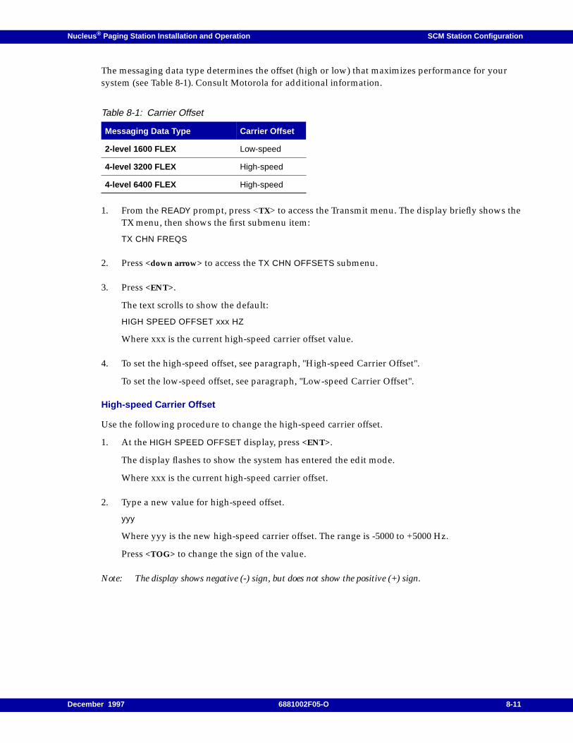
Nucleus ® Paging Station Installation and Operation SCM Station Configuration
The messaging data type determines the offset (high or low) that maximizes performance for yoursystem (see Table 8-1). Consult Motorola for additional information.
1. From the READY prompt, press <TX> to access the Transmit menu. The display briefly shows theTX menu, then shows the first submenu item:
TX CHN FREQS
2. Press <down arrow> to access the TX CHN OFFSETS submenu.
3. Press <ENT>.
The text scrolls to show the default:
HIGH SPEED OFFSET xxx HZ
Where xxx is the current high-speed carrier offset value.
4. To set the high-speed offset, see paragraph, "High-speed Carrier Offset".
To set the low-speed offset, see paragraph, "Low-speed Carrier Offset".
High-speed Carrier Offset
Use the following procedure to change the high-speed carrier offset.
1. At the HIGH SPEED OFFSET display, press <ENT>.
The display flashes to show the system has entered the edit mode.
Where xxx is the current high-speed carrier offset.
2. Type a new value for high-speed offset.
yyy
Where yyy is the new high-speed carrier offset. The range is -5000 to +5000 Hz.
Press <TOG> to change the sign of the value.
Note: The display shows negative (-) sign, but does not show the positive (+) sign.
Table 8-1: Carrier Offset
Messaging Data Type Carrier Offset
2-level 1600 FLEX Low-speed
4-level 3200 FLEX High-speed
4-level 6400 FLEX High-speed
December 1997 6881002F05-O 8-11
SCM Station Configuration Nucleus ® Paging Station Installation and Operation
3. Press <ENT>.
The display stops flashing and shows the new value:
HIGH SPEED OFFSET yyyy HZ
Press <EXIT> once to return to the TX CHN OFFSET prompt.
Press <EXIT> twice to return to the READY prompt.
Continue with the paragraph, "High-speed Splatter Filter" or paragraph, "Low-speed SplatterFilter".
Low-speed Carrier Offset
Use the following procedure to change the low-speed carrier offset.
1. At the HIGH SPEED OFFSET display, press <down arrow> to access the low-speed offset. Thedisplay shows the current value:
LOW SPEED OFFSET xxx HZ
Where xxx is the current low-speed carrier offset value.
2. Press <ENT>.
The display flashes to show the system has entered the edit mode.
3. Type a new value for low-speed offset. The range is -5000 to +5000 Hz.
yyy
Where yyy is the new high-speed carrier offset.
Press <TOG> to change the sign of the value.
Note: The display shows negative (-) sign, but does not show the positive (+) sign.
4. Press <ENT>.
The display stops flashing and shows the new value:
LOW SPEED OFFSET yyyy HZ
Where yyyy is the low-speed carrier offset value.
Press <EXIT> once to return to the TX CHN OFFSETS prompt.
Press <EXIT> twice to return to the READY prompt.
Continue with the paragraph, "High-speed Splatter Filter" or paragraph, "Low-speed SplatterFilter".
High-speed Splatter Filter
The splatter filters configure the Nucleus paging station for compatibility with other transmitters inthe system. A high-speed splatter filter configures the station for compatibility with other high-speedtransmitters in the same system.
8-12 6881002F05-O December 1997
Nucleus ® Paging Station Installation and Operation SCM Station Configuration
Use the following procedure to configure a Nucleus paging station for operation in a high-speedsystem.
Note: Most systems use the 88 µs splatter filter. However, when 20 kHz channel spacing is required, the160 µs splatter filter is applied to meet adjacent channel power (ACP) specifications.
In GPS synchronized systems, all stations should use the same filter because each filter has a differentdelay value.
1. From the READY prompt, press <TX> to access the Transmit menu.
The display briefly shows the TX menu, then shows the first submenu item.
TX CHN FREQS
2. Press <down arrow> to access the HIGH SPEED SPLATTER FILTER submenu.
The display shows the current value:
HIGH SPEED SPLATTER FILTER: xxx US LOW PASS
Where xxx is 88 or 160 µs.
3. Press <ENT>.
The display flashes to show the system has entered the edit mode.
4. Press <down arrow> to display the other value for high-speed splatter filter.
5. Press <ENT>.
The text stops flashing. The text scrolls to show the splatter filter value:
HIGH SPEED SPLATTER FILTER: yyy US LOW PASS
Where yyy is the new value.
Press <EXIT> to return to the READY prompt.
Continue with the paragraph, "Nominal Binary Deviation".
Low-speed Splatter Filter
The splatter filters configure the Nucleus paging station for compatibility with other transmitters inthe system (see Table 8-2). The low-speed splatter filter is used for low-speed FLEX paging. The low-speed splatter filter has no effect on high-speed messaging.
Note: For most applications, Motorola recommends the 88 µs low pass filter.
In GPS synchronized systems, all stations should use the same filter because each of the four filters hasa different delay value.
December 1997 6881002F05-O 8-13
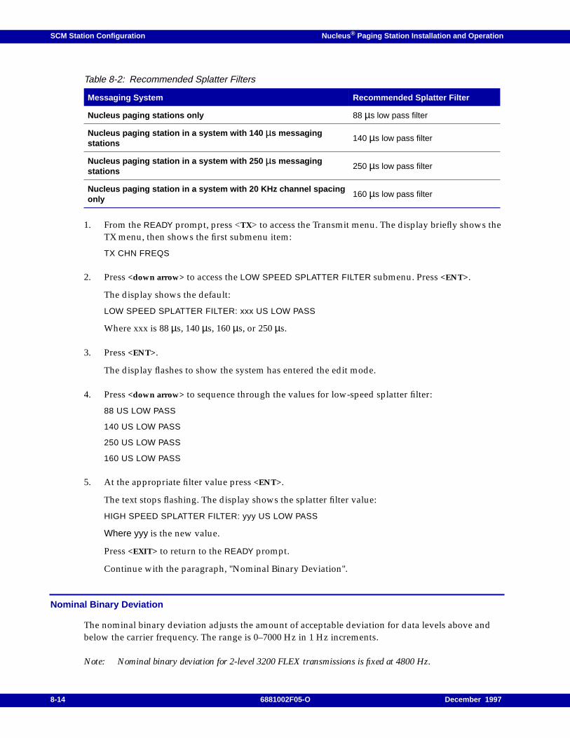
SCM Station Configuration Nucleus ® Paging Station Installation and Operation
1. From the READY prompt, press <TX> to access the Transmit menu. The display briefly shows theTX menu, then shows the first submenu item:
TX CHN FREQS
2. Press <down arrow> to access the LOW SPEED SPLATTER FILTER submenu. Press <ENT>.
The display shows the default:
LOW SPEED SPLATTER FILTER: xxx US LOW PASS
Where xxx is 88 µs, 140 µs, 160 µs, or 250 µs.
3. Press <ENT>.
The display flashes to show the system has entered the edit mode.
4. Press <down arrow> to sequence through the values for low-speed splatter filter:
88 US LOW PASS
140 US LOW PASS
250 US LOW PASS
160 US LOW PASS
5. At the appropriate filter value press <ENT>.
The text stops flashing. The display shows the splatter filter value:
HIGH SPEED SPLATTER FILTER: yyy US LOW PASS
Where yyy is the new value.
Press <EXIT> to return to the READY prompt.
Continue with the paragraph, "Nominal Binary Deviation".
Nominal Binary Deviation
The nominal binary deviation adjusts the amount of acceptable deviation for data levels above andbelow the carrier frequency. The range is 0–7000 Hz in 1 Hz increments.
Note: Nominal binary deviation for 2-level 3200 FLEX transmissions is fixed at 4800 Hz.
Table 8-2: Recommended Splatter Filters
Messaging System Recommended Splatter Filter
Nucleus paging stations only 88 µs low pass filter
Nucleus paging station in a system with 140 µs messagingstations
140 µs low pass filter
Nucleus paging station in a system with 250 µs messagingstations
250 µs low pass filter
Nucleus paging station in a system with 20 KHz channel spacingonly
160 µs low pass filter
8-14 6881002F05-O December 1997
Nucleus ® Paging Station Installation and Operation SCM Station Configuration
Use the following procedure to set the nominal binary deviation:
1. From the READY prompt, press <TX> to access the Transmit menu. The display briefly shows theTX menu, then shows the first submenu item.
TX CHN FREQS
2. Press <down arrow> to access the NOMINAL BINARY DEVIATION submenu. The display shows thecurrent value:
NOMINAL BINARY DEVIATION xxxx HZ
Where xxxx is the current binary deviation value for the station.
3. Press <ENT>.
The display flashes to show the system has entered the edit mode.
4. Type the value for nominal binary deviation.
5. Press <ENT>.
The text stops flashing. The text scrolls to show the binary deviation value:
NOMINAL BINARY DEVIATION yyyy HZ
Where yyyy is the new value.
Press <EXIT> to return to the READY prompt.
Continue with the paragraph, "Special Transmitter Setup".
Special Transmitter Setup
The special transmitter setup procedures include setup for transmitter data and the relationshipbetween the transmitter and a receiver.
Inverted Transmitter Data
The Nucleus paging station can be configured to invert messaging data at the transmitter output. Thisconfiguration procedure defines the data level for each type of messaging data and 2-level or 4-leveltransmission. For an explanation of these inversion patterns, see Figure 8-1 and Table 8-3.
December 1997 6881002F05-O 8-15
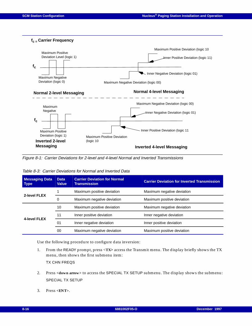
SCM Station Configuration Nucleus ® Paging Station Installation and Operation
Figure 8-1: Carrier Deviations for 2-level and 4-level Normal and Inverted Transmissions
Use the following procedure to configure data inversion:
1. From the READY prompt, press <TX> access the Transmit menu. The display briefly shows the TXmenu, then shows the first submenu item:
TX CHN FREQS
2. Press <down arrow> to access the SPECIAL TX SETUP submenu. The display shows the submenu:
SPECIAL TX SETUP
3. Press <ENT>.
Table 8-3: Carrier Deviations for Normal and Inverted Data
Messaging DataType
DataValue
Carrier Deviation for NormalTransmission
Carrier Deviation for Inverted Transmission
2-level FLEX1 Maximum positive deviation Maximum negative deviation
0 Maximum negative deviation Maximum positive deviation
4-level FLEX
10 Maximum positive deviation Maximum negative deviation
11 Inner positive deviation Inner negative deviation
01 Inner negative deviation Inner positive deviation
00 Maximum negative deviation Maximum positive deviation
fc
Normal 2-level Messaging
Maximum NegativeDeviation (logic 0)
Maximum Positive Deviation (logic 10
Normal 4-level Messaging
fc = Carrier Frequency
Maximum PositiveDeviation Level (logic 1)
Maximum Negative Deviation (logic 00)
Inner Negative Deviation (logic 01)
Inner Positive Deviation (logic 11)
fc
Inverted 2-levelMessaging
Maximum PositiveDeviation (logic 1)
Maximum Negative Deviation (logic 00)
Inverted 4-level Messaging
MaximumNegative
Maximum Positive Deviation(logic 10
Inner Positive Deviation (logic 11
Inner Negative Deviation (logic 01)
8-16 6881002F05-O December 1997
Nucleus ® Paging Station Installation and Operation SCM Station Configuration
The display shows the default:
TX DATA INVERT: DISABLED
4. Press <ENT>.
The display flashes to show the system has entered the edit mode.
5. Press <TOG>.
The display shows the new mode:
ENABLED
6. Press <ENT>.
The display stops flashing and shows the new value:
TX DATA INVERT: ENABLED
Press <EXIT> once to return to the SPECIAL TX SETUP prompt.
Press <EXIT> twice to return to the READY prompt.
The the transmitter site contains a receiver, continue with the paragraph, "Transmitter EqualsReceiver".
If the transmitter site does not contain a receiver, continue with the paragraph, "Idle Deviation".
Transmitter Equals Receiver
A system with a collocated monitor receiver tuned to the same frequency as a station transmitterfrequency risks receiver desensitization. This procedure enables the transmitter antenna and circuitryto switch to receiving when required.
Note: This procedure does not affect other transmit channels.
Use the following procedure to enable TX=RX:
1. From the READY prompt, press <TX> to access the Transmit menu. The display briefly shows theTX menu, then shows the first submenu item:
TX CHN FREQS
2. Press <down arrow> to access the SPECIAL TX SETUP submenu.
CAUTION
Motorola sets the value for receiver type during manufacturing. Do not change this setting.
December 1997 6881002F05-O 8-17
SCM Station Configuration Nucleus ® Paging Station Installation and Operation
3. Press <ENT>.
The display shows the first item of the SPECIAL TX SETUP selection:
TX DATA INVERT: DISABLED
4. Press <down arrow> to access the TX=RX submenu:
TX=RX:
5. Press <ENT>.
The display shows the default:
TX=RX: DISABLED
6. Press <ENT>.
The display flashes to show the system has entered the edit mode.
7. Press <TOG>.
The display stops flashing:
ENABLED
8. Press <ENT>.
The display shows the new value:
TX=RX: ENABLED
Press <EXIT> once to return to the SPECIAL TX SETUP prompt.
Press <EXIT> twice to return to the READY prompt.
Continue with the paragraph, "Transmitter Equals Receiver Channel".
Transmitter Equals Receiver Channel
This procedure causes the transmit channel to switch to a frequency 100 kHz above or below thenormal transmit frequency whenever the transmitter is not keyed.
Use the following procedure to configure the receiver channel:
1. From the READY prompt, press <TX> to access the Transmit menu. The display briefly shows theTX menu, then shows the first submenu item.
TX CHN FREQS
2. Press <down arrow> to access the SPECIAL TX SETUP submenu.
CAUTION
Motorola sets the value for receiver type during manufacturing. Do not change this setting.
8-18 6881002F05-O December 1997
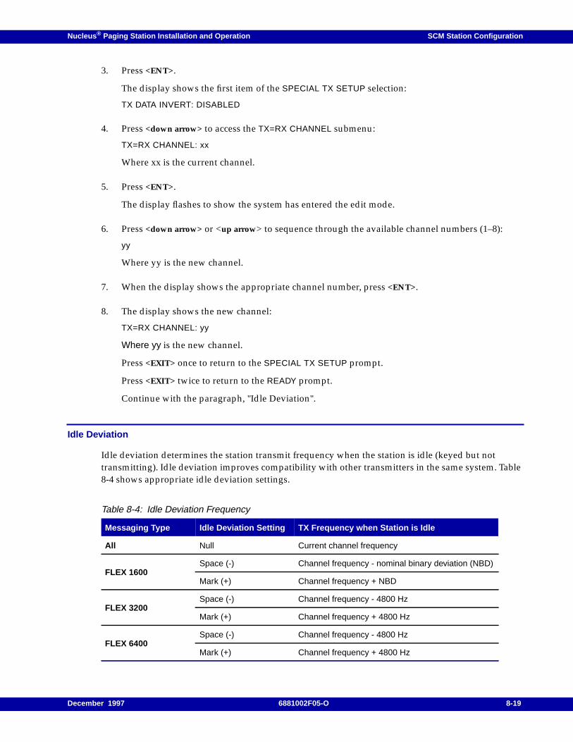
Nucleus ® Paging Station Installation and Operation SCM Station Configuration
3. Press <ENT>.
The display shows the first item of the SPECIAL TX SETUP selection:
TX DATA INVERT: DISABLED
4. Press <down arrow> to access the TX=RX CHANNEL submenu:
TX=RX CHANNEL: xx
Where xx is the current channel.
5. Press <ENT>.
The display flashes to show the system has entered the edit mode.
6. Press <down arrow> or <up arrow> to sequence through the available channel numbers (1–8):
yy
Where yy is the new channel.
7. When the display shows the appropriate channel number, press <ENT>.
8. The display shows the new channel:
TX=RX CHANNEL: yy
Where yy is the new channel.
Press <EXIT> once to return to the SPECIAL TX SETUP prompt.
Press <EXIT> twice to return to the READY prompt.
Continue with the paragraph, "Idle Deviation".
Idle Deviation
Idle deviation determines the station transmit frequency when the station is idle (keyed but nottransmitting). Idle deviation improves compatibility with other transmitters in the same system. Table8-4 shows appropriate idle deviation settings.
Table 8-4: Idle Deviation Frequency
Messaging Type Idle Deviation Setting TX Frequency when Station is Idle
All Null Current channel frequency
FLEX 1600Space (-) Channel frequency - nominal binary deviation (NBD)
Mark (+) Channel frequency + NBD
FLEX 3200Space (-) Channel frequency - 4800 Hz
Mark (+) Channel frequency + 4800 Hz
FLEX 6400Space (-) Channel frequency - 4800 Hz
Mark (+) Channel frequency + 4800 Hz
December 1997 6881002F05-O 8-19
SCM Station Configuration Nucleus ® Paging Station Installation and Operation
Note: During station alignment, idle deviation is null regardless of the setting.
Use the following procedure to change idle deviation:
1. From the READY prompt, press <TX> to access the Transmit menu.
The display briefly shows the TX menu, then shows the first submenu item.
TX CHN FREQS
2. Press <down arrow> to access the IDLE DEVIATION submenu.
IDLE DEVIATION: NULL
3. Press <ENT>.
The display flashes to show the system has entered the edit mode.
4. Press <down arrow> toto sequence through the selections (SPACE, MARK, and NULL). Each valueflashes as it appears.
5. When the display shows the appropriate selection, press <ENT>.
The display shows the new channel:
IDLE DEVIATION: MARK
Press <EXIT> to return to the READY prompt.
Continue with the paragraph, "Options (OPT1) Configuration".
8-20 6881002F05-O December 1997
Nucleus ® Paging Station Installation and Operation SCM Station Configuration
Options (OPT1) Configuration
This section describes the option configuration procedures available from the OPT1 menu. Theseprocedures include the following:
• Setting antenna relays
• Setting up external circulators
• Enabling or disabling channel mapped power
Antenna Relay
This procedure enables the use of an antenna relay option (X371) for use with the Nucleus pagingstation.
1. From the READY prompt, press <OPT1> to access the Options 1 menu.
The display briefly shows the OPT1 menu, then shows the ANTENNA RELAY submenu:
ANTENNA RELAY: DISABLED
2. Press <ENT>.
The display flashes to show the system has entered the edit mode.
3. To change the configuration, press <TOG>.
The display flashes:
ENABLED
4. Press <ENT>.
The display stops flashing and shows the new value:
ANTENNA RELAY: ENABLED
Press <EXIT> to return to the READY prompt.
Continue with the paragraph, "External Circulator".
CAUTION
Motorola sets the value for antenna relay during manufacturing. Do not change this settingunless the change must be made. Consult Motorola engineering before performing thisprocedure.
Display the alignment channels from the STN menu and CURRENT TX CHN submenu. Thisprocedure does not automatically select the alignment channels. Do not attempt to select anyalignment channels using the CURRENT TX CHN parameter.
December 1997 6881002F05-O 8-21
SCM Station Configuration Nucleus ® Paging Station Installation and Operation
External Circulator
This procedure configures the Nucleus paging station to accommodate the external circulator installedin it (option X676 or option X677).
Note: Set this parameter to PRESENT if the station has either option.
Use the following procedure to configure a circulator:
1. From the READY prompt, press <OPT1> to access the Options 1 menu.
The display briefly shows the OPT1 menu, then shows the ANTENNA RELAY submenu:
ANTENNA RELAY: DISABLED
2. Press <down arrow> to access the EXT CIRCULATOR submenu.
The display shows the current value:
EXT CIRCULATOR: NOT PRESENT
3. Press <ENT>.
The text flashes to show the system has entered the edit mode.
4. To change the configuration, press <TOG>.
The display shows the new value:
PRESENT
5. Press <ENT>.
The display shows the value:
EXT CIRCULATOR: PRESENT
Press <EXIT> to return to the READY prompt.
If the system is channel mapped, continue with the paragraph, "Channel Mapped Power". If thestation is not channel mapped, continue with the paragraph, "Alarm Setup (ASET)Configuration".
CAUTION
Motorola sets the value for external circulator during manufacturing. Do not change thissetting unless the change must be made. Consult Motorola engineering before performing thisprocedure.
8-22 6881002F05-O December 1997
Nucleus ® Paging Station Installation and Operation SCM Station Configuration
Channel Mapped Power
The channel mapping feature provides a programmable power level for each channel. Use thefollowing procedure to enable the channel-mapped power feature.
1. From the READY prompt, press <OPT1> to access the Options 1 menu.
The display briefly shows the OPT1 menu, then shows the ANTENNA RELAY submenu:
ANTENNA RELAY: DISABLED
2. Press <down arrow> to access the CHN MAPPED POWER submenu.
The text scrolls to show the default:
CHN MAPPED PWR: DISABLED
3. Press <ENT>.
The display flashes to show the system has entered the edit mode.
4. Press <TOG>.
The display flashes the new value:
ENABLED
5. Press <ENT>.
The display stops flashing and shows the new value:
CHN MAPPED PWR: ENABLED
Press <EXIT> to return to the READY prompt.
Continue with the paragraph, "Alarm Setup (ASET) Configuration".
December 1997 6881002F05-O 8-23
SCM Station Configuration Nucleus ® Paging Station Installation and Operation
Alarm Setup (ASET) Configuration
This section describes the alarm setup configuration procedures available from the ASET menu. Theseprocedures include the following:
• Setting alarms for non-channel mapped systems
• Setting alarms for channel mapped systems
Alarms for Non-channel Mapped Power Systems
Configuration for non-channel mapped systems affects the following alarms:
• Forward power alarm
• Reflected power alarm
• External forward alarm
• External reflected power alarm
This procedure programs the thresholds (points) that cause the system to declare an alarm. Use thisprocedure to configure any of the four alarms. In a nonchannel mapped system, one setting for eachalarm for the system applies to every channel.
Note: The system makes all measurements when the station keys.
EXT WM FWD PWR ALM PT and EXT WM RFL PWR ALM PT require an external Wattmeter.
Use the following procedure to program alarm thresholds for nonchannel mapped stations:
1. From the READY prompt, press <ASET> to access the Alarm Setup menu.
The display briefly shows the ASET menu, then shows the NON-CHAN MAPPED PWR ALARMSsubmenu:
NON-CHAN MAPPED PWR ALARMS
2. Press <ENT>.
The first selection of the submenu appears:
FWD PWR ALM PT: xxx W
Where xxx is the current alarm threshold.
3. Press <ENT>.
The display flashes to show the system has entered the edit mode.
4. Type a threshold value for this alarm.
The display shows this value:
yyy
Where yyy is the new alarm threshold.
8-24 6881002F05-O December 1997
Nucleus ® Paging Station Installation and Operation SCM Station Configuration
5. Press <ENT>.
The display shows the value:
FWD PWR ALM PT: yyy W
6. Press <down arrow> to access the next alarm.
7. Perform Step 3 through Step 6 for each alarm.
Press <EXIT> once to return to the NON CHN MAPPED ALARM prompt.
Press <EXIT> twice to return to the READY prompt.
Alarm Thresholds for Channel-mapped Systems
The configuration for channel-mapped systems affects the following alarms:
• Forward power alarm (channel 1–8) (INT FWD CHN MAPPED ALRM)
• Reflected power alarm (channel 1–8) (INT FRL CHN MAPPED ALRM)
• External forward alarm (channel 1–8) (EXT FWD CHN MAPPED ALRM)
• External reflected power alarm (channel 1–8) (EXT FWD CHN MAPPED ALRM)
This procedure programs the thresholds (“points”) that cause the system to declare an alarm.
Note: The system makes all measurements when the station keys.
The EXT WM FWD PWR ALM PT and EXT WM RFL PWR ALM PT alarms require an externalWattmeter.
Internal Forward Power Alarms
Use the following procedure to configure forward power alarm thresholds:
1. From the READY prompt, press <ASET> to access the Alarm Setup menu.
The display briefly shows the ASET menu, then shows the INT FWD CHN MAPPED ALMS submenuwith the current value for the first channel:
INT FWD CHN MAPPED ALMS
2. Press <ENT>.
The display flashes to show the system has entered the edit mode.
3. Type a new value for the forward power alarm for the channel.
The display flashes:
yyy
Where yyy is the new forward power alarm for the channel.
December 1997 6881002F05-O 8-25
SCM Station Configuration Nucleus ® Paging Station Installation and Operation
4. Press <ENT>.
The display shows the new value.
INT FWD CHN MAPPED CHN 1 ALRM PT: xxx W
Where xxx is the current value.
5. Press <down arrow> to access the forward power alarm for the next channel.
6. Perform Step 2 through Step 5 to set the forward power alarm thresholds for other channels.
Press <EXIT> to return to the INT FWD CHN MAPPED ALRM prompt.
Press <EXIT> twice to return to the READY prompt.
Continue with paragraph, "Reflected Power Alarms".
Reflected Power Alarms
Use the following procedure to configure reflected power alarm thresholds:
1. From the READY prompt, press <ASET> to access the Alarm Setup menu.
The display briefly shows the ASET menu, then shows the INT FWD CHN MAPPED ALMS submenuwith the current value for the first channel:
CHN 1 FWD ALM PT: xxx W
Where xxx is the current forward power alarm for the channel.
2. Press <down arrow> to access the INT RFL CHN MAPPED ALMS submenu.
3. Press <ENT>.
The display shows the first channel for configuration:
CHN 1 RFL ALM PT: xxx W
Where xxx is the current value.
4. Press <ENT>.
The display flashes to show the system has entered the edit mode.
5. Type a new value for the forward power alarm for the channel.
The display flashes:
yyy
Where yyy is the new forward power alarm for the channel:
8-26 6881002F05-O December 1997
Nucleus ® Paging Station Installation and Operation SCM Station Configuration
6. Press <ENT>.
The display shows the new value
CHN 1 RFL ALM PT: xxx W
Where xxx is the current value.
7. Press <down arrow> to access the forward power alarm for the next channel.
8. Perform Step 4 through Step 7 to set the forward power alarm thresholds for other channels.
Press <EXIT> to return to the INT FWD CHN MAPPED ALRM prompt.
Press <EXIT> twice to return to the READY prompt.
If the system contains an external Wattmeter, continue with the paragraph, "External ForwardPower Alarms".
If the system does not contain an external Wattmeter, continue with the paragraph,"Configuration (CNFG)".
External Forward Power Alarms
Use the following procedure to configure forward power alarm thresholds measured at a Wattmeter:
1. From the READY prompt, press <ASET> to access the Alarm Setup menu.
The display briefly shows the ASET menu, then shows the INT FWD CHN MAPPED ALMS submenuwith the current value for the first channel:
INT FWD CHN MAPPED ALMS: xxx W
2. Press <down arrow> to access the EXT FWD CHN MAPPED ALMS submenu.
3. Press <ENT>.
The display shows the first channel for configuration:
CHN 1 EXT FWD CHN MAPPED ALM PT: xxx W
Where xxx is the current value.
4. Press <ENT>.
The display flashes to show the system has entered the edit mode.
5. Type a new value for the external forward power alarm for the channel. The display flashes thenew value:
yyy
Where yyy is the new value.
December 1997 6881002F05-O 8-27
SCM Station Configuration Nucleus ® Paging Station Installation and Operation
6. Press <ENT>.
The display stops flashing and shows the new value:
CHN 1 EXT FWD ALM PT: yyy W
7. Press <down arrow> to access the external forward power alarm for the next channel.
8. Perform Step 3 through Step 7 to configure forward power alarm thresholds for other channels.
Press <EXIT> to return to the INT FWD CHN MAPPED ALMS prompt.
Press <EXIT> twice to return to the READY prompt.
If the system contains an external Wattmeter, continue with the paragraph, "External ReflectedPower Alarms".
If the system does not contain an external Wattmeter, continue with the paragraph,"Configuration (CNFG)".
External Reflected Power Alarms
Use the following procedure to configure forward power alarm thresholds:
1. From the READY prompt, press <ASET> to access the Alarm Setup menu.
The display briefly shows the ASET menu, then shows the INT FWD CHN MAPPED ALMS submenuwith the current value for the first channel:
CHN 1 FWD ALM PT: xxx W
2. Press <down arrow> to access the EXT RFL CHN MAPPED ALMS submenu.
3. Press <ENT>.
The display shows the first channel for configuration:
CHN 1 EXT RFL ALM PT: xxx W
Where xxx is the current value.
4. Press <ENT>.
The display flashes to show the system has entered the edit mode.
5. Type a new value for the external reflected power alarm for the channel:
yyy
Where yyy is the new value.
6. Press <ENT>.
The text stops flashing and shows the new value.
CHN 1 EXT RFL ALM PT: yyy W
7. Press <down arrow> to access the external reflected power alarm for the next channel.
8-28 6881002F05-O December 1997

Nucleus ® Paging Station Installation and Operation SCM Station Configuration
8. Perform Step 3 through Step 7 to configure reflected power alarm thresholds for other channels.
Press <EXIT>to return to the INT FWD CHN MAPPED ALM prompt.
Press <EXIT> twice to return to the READY prompt.
Continue with the paragraph, "Configuration (CNFG)".
December 1997 6881002F05-O 8-29
SCM Station Configuration Nucleus ® Paging Station Installation and Operation
Configuration (CNFG)
This section describes the configuration procedures available from the CNFG menu. These proceduresinclude the following:
• Setting up battery revert
• Setting up external Wattmeter type
• Setting network control type
• Setting receiver type
• Setting special key select
• Setting seconds
Note: The first option, MAX PWR, is read only.
Battery Revert
Battery revert provides power if AC power fails. Two options are available: option X30 or option X43.If the system uses one of the battery revert options, use this procedure to configure or verify theoption.
This procedure configures these aspects of battery revert:
• Battery type
• Battery charging
• Battery backup
Battery Type
Use the following procedure to configure the battery type:
1. From the READY prompt, press <CNFG> to access the Configuration menu.
The display briefly shows the CNFG menu, then shows the first submenu item:
MAX PWR
2. Press <down arrow> to access the BATTERY REVERT SETUP submenu.
3. Press <ENT>.
The display shows the BATTERY TYPE selection:
BATTERY TYPE: BATTERY REVERT DISABLED
4. Press <ENT>.
The display flashes to show the system has entered the edit mode.
DISABLED
8-30 6881002F05-O December 1997
Nucleus ® Paging Station Installation and Operation SCM Station Configuration
5. Press <down arrow> or <TOG> to select SEALED LEAD CALCIUM. The display flashes:
SEALED LEAD CALCIUM
6. Press <ENT>.
The display stops flashing and shows the new type:
BATTERY TYPE: SEALED LEAD CALCIUM
Press <EXIT> once to return to the READY prompt.
Continue with the paragraph, "Charging Option".
Charging Option
Use this procedure to configure the charging option:
1. From the READY prompt, press <CNFG> to access the Configuration menu.
The display briefly shows the CNFG menu, then shows the first submenu item:
MAX PWR
2. Press <down arrow> to access the BATTERY REVERT SETUP submenu.
3. Press <ENT>.
The display shows the BATTERY TYPE selection:
BATTERY TYPE: BATTERY REVERT ENABLED
4. Press <down arrow> to access the CHARGING selection. The display shows the currentconfiguration:
CHARGING: DISABLED
5. Press <ENT>.
The display flashes to show the system has entered the edit mode.
6. Press <down arrow>. The display flashes the new value:
ENABLED
7. Press <ENT>.
The text stops flashing and shows the CHARGING option:
CHARGING: ENABLED
Press <EXIT> once to return to BATTERY REVERT SETUP prompt.
Press <EXIT> twice to return to the READY prompt.
Continue with the paragraph, "Backup Option".
December 1997 6881002F05-O 8-31
SCM Station Configuration Nucleus ® Paging Station Installation and Operation
Backup Option
The backup option selects backup mode during an AC power failure. The mode depends on theoption:
• Option X43 requires the backup station mode.
• Option X30 requires the backup control mode.
Use the following procedure to configure the backup option:
Use this procedure to configure the charging option:
1. From the READY prompt, press <CNFG> to access the Configuration menu.
The display briefly shows the CNFG menu, then shows the first submenu item:
MAX PWR
2. Press <down arrow> to access the BATTERY REVERT SETUP submenu.
The display shows the BATTERY TYPE option:
BATTERY TYPE: BATTERY REVERT ENABLED
3. Press <ENT>.
4. Press <down arrow> to access the BACKUP selection.
The display shows the current selection:
BACKUP: BACKUP STATION
5. Press <ENT>.
The display flashes to show the system has entered the edit mode.
6. To configure battery backup, press <down arrow> to select BACKUP CONTROL. The displayflashes:
BACKUP CONTROL
7. Press <ENT>.
The text stops flashing and shows the BACKUP option:
BACKUP: BACKUP CONTROL
Press <EXIT> once to return to BATTERY REVERT SETUP prompt.
Press <EXIT> twice to return to the READY prompt.
If the station has an external Wattmeter, continue with the paragraph, "External Wattmeter".If the station does not have an external Wattmeter, continue with the paragraph, "Control Type".
Fixed Cutback Reduction Percent
The fixed cutback reduction percent option determines the level of cutback in power that the stationuses to conserve power when using battery revert. This option is not available for this release.
8-32 6881002F05-O December 1997
Nucleus ® Paging Station Installation and Operation SCM Station Configuration
External Wattmeter
This procedure identifies the type of Wattmeter being used at the station. At the current time, theNucleus paging station uses the Wattmeter identified as Class 1 External. Use this procedure toconfigure the external Wattmeter.
1. From the READY prompt, press <CNFG> to access the Configuration menu.
The display briefly shows the CNFG menu, then shows the first submenu item:
MAX PWR
2. Press <down arrow> to access the EXT WATTMETER TYPE submenu.
3. Press <ENT>.
The display shows the default:
EXT WATTMETER TYPE: NONE
4. Press <ENT>.
The display flashes to show the system has entered the edit mode.
5. Press <down arrow> to sequence through the selections.
The display flashes the values:
NONE
CLASS 1 EXT
CLASS 2 EXT
CLASS 3 EXT
CLASS 4 EXT
6. When the display shows the CLASS 1 EXT selection, press <ENT>.
The display shows the Wattmeter selection:
EXT WATTMETER TYPE: CLASS 1 EXT
Press <EXIT> once to return to the READY prompt.
Continue with the paragraph, "Control Type".
Control Type
This procedure configures the type of network controller being used in the system. The types are:
• C-NET Control Point
• RF-Conductor! (RF-C!) controller and the RF-Baton! (RF-B!) transmitter controller
December 1997 6881002F05-O 8-33
SCM Station Configuration Nucleus ® Paging Station Installation and Operation
Use the following procedure to configure the station control type:
1. From the READY prompt, press <CNFG> to access the Configuration menu.
The display briefly shows the CNFG menu, then shows the first submenu item:
MAX PWR
2. Press <down arrow> to access the CONTROL submenu.
The display shows the default control type:
CONTROL: INTERNAL CNET
This control type is correct for an NIU.
3. To configure the station for an RF-B! transmitter controller, press <ENT>.
The display flashes to show the system has entered the edit mode.
4. Press <down arrow>.
The display flashes the selection:
EXT SYNCH LOCAL CONTROL.
5. Press <ENT>.
The text stops flashing. The display shows the control type:
CONTROL: EXT SYNCH LOCAL CONTROL
Press <EXIT> to return to the READY prompt.
If the station has a receiver, continue with the paragraph, "Receiver Type".
If the station supports external keying, continue with the paragraph, "Special Key Select".
Receiver Type
The receiver type submenu configures the station for an internal monitor receiver or link receiver. Usethe following procedure to configure a receiver. Then perform the procedures in paragraph,"Transmitter Equals Receiver" and paragraph, "Transmitter Equals Receiver Channel".
Use the following procedure to configure the receiver type:
1. From the READY prompt, press <CNFG> to access the Configuration menu.
The display briefly shows the CNFG menu, then shows the first submenu item:
MAX PWR
CAUTION
Motorola sets the value for receiver type during manufacturing. Do not change thissetting unless you install a receiver in the station.
8-34 6881002F05-O December 1997
Nucleus ® Paging Station Installation and Operation SCM Station Configuration
2. Press <down arrow> to access the RX TYPE submenu.
The display shows the default control type:
RX TYPE: NO INTERNAL
Continue with the paragraph, "Link Receiver" or paragraph, "Monitor Receiver".
Link Receiver
Use the following procedure to configure a link receiver.
1. At the RX TYPE: prompt, press <ENT>.
The display flashes to show the system has entered the edit mode.
2. Press <down arrow> to access INTERNAL LINK.
The display flashes the selection:
INTERNAL LINK
3. Press <ENT>.
The display stops flashing and shows the control type:
RX TYPE: INTERNAL LINK
Press <EXIT> to return to the READY prompt.
If the station supports external keying, continue with the paragraph, "Special Key Select".
Monitor Receiver
Use the following procedure to configure a monitor receiver.
1. At the RX TYPE: prompt, press <ENT>.
The display flashes to show the system has entered the edit mode.
2. Press <down arrow> to access INTERNAL MONITOR. The display flashes this selection:
INTERNAL MONITOR
3. Press <ENT>.
The display stops flashing and shows the new selection:
RX TYPE: INTERNAL MONITOR
Press <EXIT> to return to the READY prompt.
If the station supports external keying, continue with the paragraph, "Special Key Select".
December 1997 6881002F05-O 8-35
SCM Station Configuration Nucleus ® Paging Station Installation and Operation
Special Key Select
The special key select submenu enables external keying and configures the station for external high orexternal low. Use the external low selection if the station has an internal NIU transmitter controller orexternal synchronous control (external NIU transmitter controller or an RF-B! transmitter controller).
Use the following procedure to configure external keying:
1. From the READY prompt, press <CNFG> to access the Configuration menu.
The display briefly shows the CNFG menu, then shows the first submenu item:
MAX PWR
2. Press <down arrow> to access the SPECIAL KEY SELECT submenu.
The display shows the default control type:
SPECIAL KEY SELECT: NONE
3. Press <ENT>.
The display flashes to show the system has entered the edit mode.
4. Press <down arrow> to sequence through the selections and select external low keying:
– CD INT–not supported
– CD EXT–not supported
– SPCL KEY–not supported
– FAST LOW–not supported
– FAST HIGH–not supported
– EXT LOW–external low key
– EXT HIGH–not supported
5. Press <ENT>.
The display stops flashing and shows the key select:
SPECIAL KEY SELECT: EXT LOW
Press <EXIT> to return to the READY prompt.
This procedure concludes configuration for the Nucleus paging station.
8-36 6881002F05-O December 1997
Nucleus ® Paging Station Installation and Operation / Chapter 9
SCM Station Alarms, Status,Troubleshooting, and Alignment 9
This chapter describes operational and troubleshooting procedures for the Nucleus paging stationusing the keypad and a test equipment setup. The Nucleus paging station supports power outputadjustment and alignment with manual and automatic procedures. The station also displays statusand alarms. This chapter describes these procedures. This chapter contains the following information:
Station Status, 9-2
Controlling Access to the Nucleus Paging Station, 9-4Disabling Remote Access (Enabling Maintenance Access), 9-4Enabling Remote Access (Disabling Maintenance Access), 9-5Disabling Messaging Access, 9-5Enabling Messaging Access, 9-6Reading Disable Status, 9-6
Alarms, 9-8Clearing Alarms, 9-9Resetting Station Alarms from the Alarms Menu, 9-14
Troubleshooting, 9-16General Troubleshooting Procedure, 9-16Test Setup, 9-16Verifying Transmitter Circuitry, 9-18Using the Service Mode, 9-21Select a Test Pattern, 9-22Key on Symbol, 9-22
Alignment, 9-24Test Equipment and Setup, 9-24Calibration for the RF Power Output Level, 9-25Power for a Non-channel Mapped Station, 9-26Power for a Channel Mapped Station, 9-27Station Power Calibration, 9-28External Wattmeter Calibration for Stations with Circulator Options, 9-31Alignment for an HSO or UHSO Reference, 9-32
Advanced Power Measurements, 9-36Measurement Issues, 9-36Automatic Alignment, 9-37Decibel Mathematics, 9-37
December 1997 6881002F05-O 9-1
SCM Station Alarms, Status, Troubleshooting, and Alignment Nucleus ® Paging Station Installation and Operation
Station Status
The Nucleus paging station shows status values for power levels, software versions, and thealignment values for the Exciter and the Station Control Module (SCM). The station also controlsaccess to messaging and maintenance.
The Nucleus paging station provides a method of reading the status of the station withoutinterrupting messaging. Station status is read-only information. The menu does not allow changes indata.
The Station Status menu provides status on the following station parameters:
• Forward power level measured during the most recent station key-up
• Reflected power level measured during the most recent station key-up
• Voltage standing wave ratio (VSWR) level measured during the most recent station key-up
• External Wattmeter reading for forward power level measured during the most recent stationkey-up
• External Wattmeter reading for reflected power level measured during the most recent stationkey-up
• External Wattmeter reading for VSWR level measured during the most recent station key-up
• Software versions for installed components:
– Application software
– Exciter software
– Boot software
– Alignment ID- Station Control Module (SCM) alignment ID- Exciter alignment ID
Use the following procedure to access station status:
1. From the READY prompt, press <STAT> to access the Status menu.
The display briefly shows the STAT menu, then shows the first submenu item:
FWD PWR: sss W
Where sss is the forward power value in Watts.
2. Press <down arrow> to sequence through the submenus (see Table 9-1).
9-2 6881002F05-O December 1997
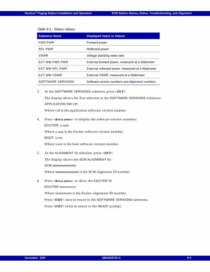
Nucleus ® Paging Station Installation and Operation SCM Station Alarms, Status, Troubleshooting, and Alignment
3. At the SOFTWARE VERSIONS submenu press <ENT>.
The display shows the first selection in the SOFTWARE VERSIONS submenu:
APPLICATION SW t.ttt
Where t.ttt is the application software version number.
4. Press <down arrow> to display the software version numbers:
EXCITER: u.uuu
Where u.uuu is the Exciter software version number.
BOOT: v.vvv
Where v.vvv is the boot software version number.
5. At the ALIGNMENT ID selection, press <ENT>.
The display shows the SCM ALIGNMENT ID:
SCM wwwwwwwwww
Where wwwwwwwwww is the SCM alignment ID number
6. Press <down arrow> to show the EXCITER ID
EXCITER xxxxxxxxxx
Where xxxxxxxxxx is the Exciter alignment ID number.
Press <EXIT> once to return to the SOFTWARE VERSIONS submenu.
Press <EXIT> twice to return to the READY prompt.
Table 9-1: Status Values
Submenu Items Displayed Value or Values
FWD PWR Forward power
RFL PWR Reflected power
VSWR Voltage standing wave ratio
EXT WM FWD PWR External forward power, measured at a Wattmeter
EXT WM RFL PWR External reflected power, measured at a Wattmeter
EXT WM VSWR External VSWR, measured at a Wattmeter
SOFTWARE VERSIONS Software version numbers and alignment numbers
December 1997 6881002F05-O 9-3
SCM Station Alarms, Status, Troubleshooting, and Alignment Nucleus ® Paging Station Installation and Operation
Controlling Access to the Nucleus Paging Station
The Nucleus paging station supports methods for disabling it. Disabling a station is appropriateduring the following circumstances:
• Installation (after the station power up, but before testing and alignment)
• Local maintenance
If maintenance access is enabled (remote access disabled), the system cannot key for a remotemessaging command.
The procedure for controlling access also shows the disable status.
Disabling Remote Access (Enabling Maintenance Access)
Note: Enabling maintenance access disables remote access. Disabling maintenance access enables remoteaccess.
Use this procedure to disable remote access to a Nucleus paging station:
1. From the READY prompt, press <DIS> to access the Disable menu.
The display briefly shows the DIS menu, then shows the first submenu item:
MAINT ACCESS: DISABLED
2. Press <ENT>.
The display flashes to show the system has entered the edit mode.
3. Press <TOG>.
The display flashes to show the change:
ENABLED
4. Press <ENT>.
The display stops flashing and shows the status:
MAINT ACCESS: ENABLED.
Press <EXIT> to return to the READY prompt.
DANGER
Disable remote access and enable maintenance access for all repair procedures.
9-4 6881002F05-O December 1997
Nucleus ® Paging Station Installation and Operation SCM Station Alarms, Status, Troubleshooting, and Alignment
Enabling Remote Access (Disabling Maintenance Access)
Use this procedure to enable remote access to a Nucleus paging station:
1. From the READY prompt, press <DIS> to access the Disable menu.
The display briefly shows the DIS menu, then shows the first submenu item:
MAINT ACCESS: ENABLED
2. Press <ENT>.
The display flashes to show the system has entered the edit mode.
3. Press <TOG>.
The display flashes to show the change:
DISABLED
4. Press <ENT>.
The display stops flashing and shows the status:
MAINT ACCESS: DISABLED.
Press <EXIT> to return to the READY prompt.
Disabling Messaging Access
The Nucleus paging station supports remote diagnostics with messaging disabled. Use this procedureto facilitate remote diagnostics:
1. From the READY prompt, press <DIS> to access the Disable menu.
The display briefly shows the DIS menu, then shows the first submenu item:
ACCESS: DISABLED
2. Press <down arrow> to access the PAGING ACCESS submenu.
The display shows the current maintenance access status:
PAGING ACCESS: ENABLED
3. Press <ENT>.
The display flashes to show the system has entered the edit mode.
4. Press <TOG>.
The display flashes to show the change:
DISABLED
December 1997 6881002F05-O 9-5
SCM Station Alarms, Status, Troubleshooting, and Alignment Nucleus ® Paging Station Installation and Operation
5. Press <ENT>.
The display stops flashing and shows the status:
PAGING ACCESS: DISABLED.
Press <EXIT> to return to the READY prompt.
Enabling Messaging Access
Use this procedure to restore messaging:
1. From the READY prompt, press <DIS> to access the Disable menu.
The display briefly shows the DIS menu, then shows the first submenu item:
MAINT ACCESS: DISABLED
2. Press <down arrow> to access the PAGING ACCESS submenu.
The display shows the current maintenance access status:
PAGING ACCESS: DISABLED
3. Press <ENT>.
The display flashes to show the system has entered the edit mode.
4. Press <TOG>.
The display flashes to show the change:
ENABLED
5. Press <ENT>.
The display stops flashing and shows the status:
PAGING ACCESS: ENABLED.
Press <EXIT> to return to the READY prompt.
Reading Disable Status
The Disable Status submenu shows active disable states for maintenance or messaging. Use thefollowing procedure to read the status:
1. From the READY prompt, press <DIS> to access the Disable menu.
The display briefly shows the DIS menu, then shows the first submenu item.
2. Press <down arrow> to access the DISABLE STATUS submenu.
3. Press <ENT>.
The display shows the first item that is disabled. If nothing is disabled, the display shows thefollowing:
9-6 6881002F05-O December 1997

Nucleus ® Paging Station Installation and Operation SCM Station Alarms, Status, Troubleshooting, and Alignment
NO DISABLES
4. Press <down arrow> to sequence through the list of disabled items.
Press <EXIT> to return to the MAINT ACCESS submenu.
Press <EXIT> twice to return to the READY prompt.
December 1997 6881002F05-O 9-7
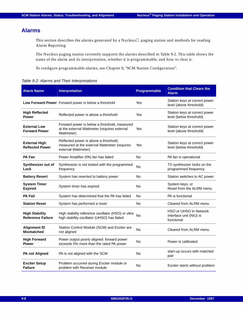
SCM Station Alarms, Status, Troubleshooting, and Alignment Nucleus ® Paging Station Installation and Operation
Alarms
This section describes the alarms generated by a Nucleus paging station and methods for readingAlarm Reporting
The Nucleus paging station currently supports the alarms described in Table 9-2. This table shows thename of the alarm and its interpretation, whether it is programmable, and how to clear it.
To configure programmable alarms, see Chapter 8, "SCM Station Configuration".
Table 9-2: Alarms and Their Interpretations
Alarm Name Interpretation ProgrammableCondition that Clears theAlarm
Low Forward Power Forward power is below a threshold YesStation keys at correct powerlevel (above threshold)
High ReflectedPower
Reflected power is above a threshold YesStation keys at correct powerlevel (below threshold)
External LowForward Power
Forward power is below a threshold, measuredat the external Wattmeter (requires externalWattmeter)
YesStation keys at correct powerlevel (above threshold)
External HighReflected Power
Reflected power is above a threshold,measured at the external Wattmeter (requiresexternal Wattmeter)
YesStation keys at correct powerlevel (below threshold)
PA Fan Power Amplifier (PA) fan has failed No PA fan is operational
Synthesizer out ofLock
Synthesizer is not locked with the programmedfrequency
NoTX synthesizer locks on theprogrammed frequency
Battery Revert System has reverted to battery power No Station switches to AC power
System TimerExpired
System timer has expired NoSystem keys, orReset from the ALRM menu
PA Fail System has determined that the PA has failed No PA is functional
Station Reset System has performed a reset No Cleared from ALRM menu
High StabilityReference Failure
High stability reference oscillator (HSO) or ultrahigh stability oscillator (UHSO) has failed
NoHSO or UHSO in NetworkInterface unit (NIU) isfunctional
Alignment IDMismatched
Station Control Module (SCM) and Exciter arenot aligned
No Cleared from ALRM menu
High ForwardPower
Power output poorly aligned: forward powerexceeds 5% more than the rated PA power
No Power is calibrated
PA not Aligned PA is not aligned with the SCM Nostart-up occurs with matchedpair
Exciter SetupFailure
Problem occurred during Exciter module orproblem with Receiver module
No Exciter starts without problem
9-8 6881002F05-O December 1997
Nucleus ® Paging Station Installation and Operation SCM Station Alarms, Status, Troubleshooting, and Alignment
Clearing Alarms
This section describes special procedures required to clear some alarms. See Chapter 13, "ReplacingModules" for the replacement procedures required to clear some alarms.
Note: Whenever the Nucleus paging station is turned off and then turned on, or reset, it issues a reset alarm.Clear this alarm from the ALRM menu. Allow the station to warm up for at least one hour beforealigning the system.
Clearing a Low Forward Power Alarm
This alarm occurs when the Nucleus paging station reads a forward alarm that is less that 95 percentof threshold. Use the following procedure to clear a low power alarm:
1. From the READY prompt, press <ALGN> to access the Alignment menu.
The display briefly shows the ALGN menu, then shows the first submenu item.
2. Press <down arrow> to access the KEY AND READ POWER submenu.
3. Press <ENT>.
The station keys.
a. If the station keys at a forward power level above the forward power alarm point, the stationclears the alarm automatically.
b. If the station keys at a low forward power level, recalibrate the power level (see Chapter 9,"SCM Station Alarms, Status, Troubleshooting, and Alignment").
4. Press <EXIT> to return to the READY prompt.
Clearing a High Reflected Power Alarm
This alarm occurs when the reflected power is higher than the programmed threshold. Use thefollowing procedure to clear a high reflected power alarm:
1. From the READY prompt, press <ALGN> to access the Alignment menu.
The display briefly shows the ALGN menu, then shows the first submenu item.
DANGER
Disable messaging before replacing a module.
CAUTION
Always replace the Exciter and the SCM as a matched pair. If the Exciter and SCM are notmatched, the mismatch results in an alarm that cannot be cleared until they are matched.
December 1997 6881002F05-O 9-9
SCM Station Alarms, Status, Troubleshooting, and Alignment Nucleus ® Paging Station Installation and Operation
2. Press <down arrow> to access the KEY AND READ POWER submenu.
3. Press <ENT>.
The station keys.
a. If the station keys at a reflected power level lower than the reference power alarm point, thestation clears the alarm automatically.
b. If the station keys at a high reflected power level, correct the power level (see Chapter 9,"SCM Station Alarms, Status, Troubleshooting, and Alignment").
4. Press <EXIT> to return to the READY prompt.
Clearing an External Low Forward Power Alarm
This alarm occurs if the station has an external Wattmeter that measures forward power at less than95 percent of the threshold. Use the following procedure to clear a external low forward power alarm:
1. From the READY prompt, press <ALGN> to access the Alignment menu.
The display briefly shows the ALGN menu, then shows the first submenu item.
2. Press <down arrow> to access the KEY AND READ EXT POWER submenu.
3. Press <ENT>.
The station keys.
a. If the station keys at a forward power level above the forward power alarm point, and theWattmeter reads the power correctly, the station clears the alarm automatically.
b. If the station keys at the correct forward power level (measured by test equipment) and theWattmeter reads the power incorrectly, recalibrate the external Wattmeter.
c. If recalibration is unsuccessful, replace the Wattmeter.
d. If the station keys at a low forward power level (measured at the Wattmeter and by testequipment), correct the power level (see Chapter 9, "SCM Station Alarms, Status,Troubleshooting, and Alignment").
4. Press <EXIT> to return to the READY prompt.
Clearing an External High Reflected Power Alarm
This alarm occurs if the station has an external Wattmeter that measures reflected alarm at a levelhigher than the threshold. Use the following procedure to clear a external high reflected power alarm:
1. From the READY prompt, press <ALGN> to access the Alignment menu.
The display briefly shows the ALGN menu, then shows the first submenu item.
2. Press <down arrow> to access the KEY AND READ EXT POWER submenu.
3. Press <ENT>.
The station keys.
9-10 6881002F05-O December 1997
Nucleus ® Paging Station Installation and Operation SCM Station Alarms, Status, Troubleshooting, and Alignment
a. If the station keys at a reflected power level lower than the forward power alarm point, andthe Wattmeter reads the power correctly, the station clears the alarm automatically.
b. If the station keys at a forward power level above the forward power alarm point (measuredby test equipment) and the Wattmeter reads the power incorrectly, recalibrate the externalWattmeter.
c. If recalibration is unsuccessful, turn off the station and replace the Wattmeter. Turn on thestation, allow it to warm up, and calibrate the Wattmeter (see Chapter 9, "SCM StationAlarms, Status, Troubleshooting, and Alignment").
d. If the station keys at a high reflected power level (measured at the Wattmeter and by testequipment), see Chapter 9, "SCM Station Alarms, Status, Troubleshooting, and Alignment"and correct the power level.
Clearing a PA Fan Alarm
The Nucleus paging station requires the PA fans to operate for the safe operation of the PA. This alarmoccurs if the fan or fans stop operating. Use the following procedure to clear a PA fan alarm.
1. Inspect the fan opening to ensure the fan mechanism can draw air.
2. Inspect the fan mechanism if possible to ensure it is clean and has power.
3. Turn off the Nucleus paging station and restart it.
4. If Step 3 was unsuccessful, turn off the station and replace the PA.
Clearing a Synthesizer out of Lock Alarm
This alarm occurs if the Nucleus paging station senses faulty synthesizer circuitry. Use the followingprocedure to clear a synthesizer out of lock alarm:
1. If the Nucleus paging station has an external NIU or RF-Baton! transmitter controller, inspectthe backplane connector and cable between the station and the transmitter controller.
2. Correct any cable or connector problems that appear.
3. If Step 2 was unsuccessful, replace the backplane.
4. If the Nucleus paging station has an internal NIU, check the LEDs on the transmitter controller toensure it is functioning normally.
5. Reset or turn off the Nucleus paging station and restart it.
6. If Step 5 was unsuccessful, turn off the station and replace the NIU.
December 1997 6881002F05-O 9-11
SCM Station Alarms, Status, Troubleshooting, and Alignment Nucleus ® Paging Station Installation and Operation
Clearing a Battery Revert Alarm
This alarm occurs when the station has an AC power failure and reverts to battery power. Use thefollowing procedure to reset the battery revert alarm:
1. Inspect the Nucleus paging station backplane connectors to see if AC power is connected to thepower supply.
2. Replace connectors as required.
3. Restore AC power to the Nucleus paging station. The alarm resets.
4. If the alarm does not reset, replace the power supply in a standard power system, or the middlepower supply in a high power system.
Clearing a System Timer Expired Alarm
This alarm occurs when the system timer expires before the station keys. Use the following procedureto reset the system timer expired alarm:
1. Use one of the following steps to reset the alarm:
– Key the system at the site. The station resets the alarm.
– Key the system remotely. The station resets the alarm.
– Reset the alarm from the alarm menu.
2. From the READY prompt, press <STN> to access the Station menu.
The display briefly shows the STN menu, then shows the first submenu item.
3. Press <down arrow> to access the SYS TIMER ALRM submenu.
4. Set the timer alarm for a period longer period.
5. Press <EXIT> to return to the READY prompt.
6. Monitor station performance to ensure the system does not repeat the alarm.
Clearing a PA Fail Alarm
This alarm occurs when the PA fails. Use the following procedure to clear the PA fail alarm:
1. Inspect the PA fans to ensure they are operating. If not, perform the steps in the paragraph,"Clearing a PA Fan Alarm".
2. Reset or restart the Nucleus paging station.
3. If Step 2 was not successful, turn off the station and replace the PA module.
4. Calibrate the station (see Chapter 9, "SCM Station Alarms, Status, Troubleshooting, andAlignment").
9-12 6881002F05-O December 1997
Nucleus ® Paging Station Installation and Operation SCM Station Alarms, Status, Troubleshooting, and Alignment
Clearing a Station Reset Alarm
This alarm occurs when the Nucleus paging station performs a power-up or reset.
Clear this alarm from the Station Alarms menu.
Clearing a High Stability Reference Fail Alarm
This alarm occurs when the oscillator fails. Use the following procedure to clear the high stabilityreference fail alarm:
1. Reset or restart the Nucleus paging station.
2. If Step 1 was unsuccessful, and the station has an external NIU, replace the cable connector.
3. Turn off the station and replace the internal or external NIU.
Clearing an Alignment ID Mismatch Alarm
This alarm occurs when the Nucleus paging station software reads the alignment ID of the SCM andExciter at start-up or reset and the alignment IDs of the two modules do not match. The Nucleuspaging station requires that the SCM and Exciter are a matched pair. Use the following procedure tocheck the alignment ID numbers:
Note: While this alarm is active, the station may perform 2-level messaging, but 4-level messaging is disabled.
1. From the READY prompt, press <STAT> to access the Status menu.
The display briefly the STAT menu, then shows the first submenu item.
2. Press <up arrow> to access the SOFTWARE VERSIONS submenu.
3. Press <ENT>.
4. Press <up arrow> to access the ALIGNMENT ID selection.
5. Press <ENT>.
The display shows the alignment ID for the SCM.
6. Press <down arrow>. The display shows the alignment ID for the Exciter.
7. If the two alignment ID numbers are not identical, turn off the station and replace the SCM andthe Exciter.
8. Clear the alarm from the Alarms menu.
December 1997 6881002F05-O 9-13
SCM Station Alarms, Status, Troubleshooting, and Alignment Nucleus ® Paging Station Installation and Operation
Clearing a High Forward Power Alarm
This alarm occurs when the forward power reading measured at the internal Wattmeter exceeds therated PA power level by more than 5 percent. In a high power station, this level is greater than 315 W(300 + 5 percent). Use the following procedure to control the high forward power:
1. Calibrate the output power (see Chapter 9, "SCM Station Alarms, Status, Troubleshooting, andAlignment").
2. Restart or reset the station.
Clearing a PA Not Aligned Alarm
This alarm occurs when the PA is not aligned (see Chapter 9, "SCM Station Alarms, Status,Troubleshooting, and Alignment").
Clearing an Exciter Start-up Failure
This alarm occurs when the Nucleus paging station senses an Exciter initialization problem or aproblem in initializing an internal receiver. Use the following procedure to clear this alarm:
1. From the READY prompt, press <RX> to access the Receiver menu.
2. The display briefly shows the RX menu, then shows the first submenu item.
If the RX FREQ RANGE submenu shows a receiver range, the station has a receiver.
3. Press <down arrow> to sequence through the submenus. Note the configuration of the receiver forfuture reference.
4. Press <EXIT> to return to the READY prompt.
5. If the station has a Receiver, turn off the station and replace the Receiver. Restart the station.
6. If the station does not have a Receiver, replace the Exciter and the SCM as a matched pair andrestart the station
Resetting Station Alarms from the Alarms Menu
This section describes the procedures for reading and clearing alarms.
Reading Alarms
Use the following procedure to read alarms:
1. At the READY prompt, press <ALMS> to access the Station Alarms menu.
The display briefly shows the ALM menu.
If no alarms are active, the display then shows the following text:
NO ALARMS
If the system has at least one current alarm, the display shows the first alarm.
9-14 6881002F05-O December 1997
Nucleus ® Paging Station Installation and Operation SCM Station Alarms, Status, Troubleshooting, and Alignment
2. Press <down arrow> to sequence through the active alarms.
3. Press <EXIT> to return to the READY prompt.
Clearing Alarms
Use the following procedure to clear alarms:
1. At the READY prompt, press <ALMS> to access the Station Alarms menu.
The display briefly shows the ALM menu.
2. If the system has at least one current alarm, the display shows the name of the first alarm andshows that it is active:
LOW FORWARD POWER: ACTIVE
3. Press <ENT> to select the alarm.
The display flashes to show the station has entered the edit mode:
ACTIVE
4. Press <TOG>.
The display stops flashing and shows the state of the alarm:
INACTIVE
5. Press <ENT>.
The station clears the alarm.
6. Press <down arrow> to sequence through the active alarms.
7. Repeat Step 3 through Step 6 to clear other active alarms.
8. Press <EXIT> to return to the READY prompt.
December 1997 6881002F05-O 9-15
SCM Station Alarms, Status, Troubleshooting, and Alignment Nucleus ® Paging Station Installation and Operation
Troubleshooting
This section describes troubleshooting the Nucleus paging station to the field replaceable unit (FRU)level.
General Troubleshooting Procedure
Repair of the Nucleus paging station is limited to replacing a known faulty module with a FRU.Return faulty modules to an authorized Motorola Service Representative.
Several methods exist for identifying a failing or failed module for replacement:
• An LED shows an alarm (see Chapter 6, "Front Panel Indicators and Controls").
• The Station Alarms menu shows an alarm (see Chapter 10, "NAC Configuration").
• The Station Status menu suggests a problem, such as falling forward power (see Chapter 11,"NAC Alignment and Equalization").
Note: This procedure uses a Motorola R2000 Series Communications Analyzer (or equivalent).
Module replacement is described in the chapter that follows (see Chapter 13, "Replacing Modules").
Test Setup
The procedure described below verifies operation of the following modules and circuits:
• Exciter
• Power Amplifier (PA)
• Power supplies
• 16.8 MHz reference oscillator circuitry
• Transmitter-related circuitry on the Station Control Board (SCB)
This procedure injects signals of known values into the circuits and measures the output signals.Incorrect measurement values indicate one or more faulty modules. Measurement values within theacceptable range verify proper operation of the modules and circuitry listed above.
Required Test Equipment
These procedures require the following test equipment:
• Motorola R2000 Series Communications Analyzer (or equivalent)
• In-line Wattmeter (Motorola Model S-1350 or equivalent)
• Dummy load (50 W station power or higher)
Equipment Setup
Note: Connect the in-line Wattmeter directly to the station transmit output cable. Connect the transmitoutput cable to the outer row of the 6-hole transmitter bracket on the back of the backplane at the rear ofthe station (see Chapter 5, "Connectors and Interfaces".
9-16 6881002F05-O December 1997
Nucleus ® Paging Station Installation and Operation SCM Station Alarms, Status, Troubleshooting, and Alignment
Use the following procedure to connect the test equipment (see Figure 9-1).
1. Connect the dummy load to the Wattmeter.
2. Disconnect the cable from the PA power alignment point.
3. Connect the PA power output alignment point to the Wattmeter.
4. Continue with the paragraph, "Verifying Transmitter Circuitry".
CAUTION
Use the connectors provided for installation. Do not use adapters or intermediate cablesbetween the transmit output cable connector (N-type) and the Wattmeter.
December 1997 6881002F05-O 9-17
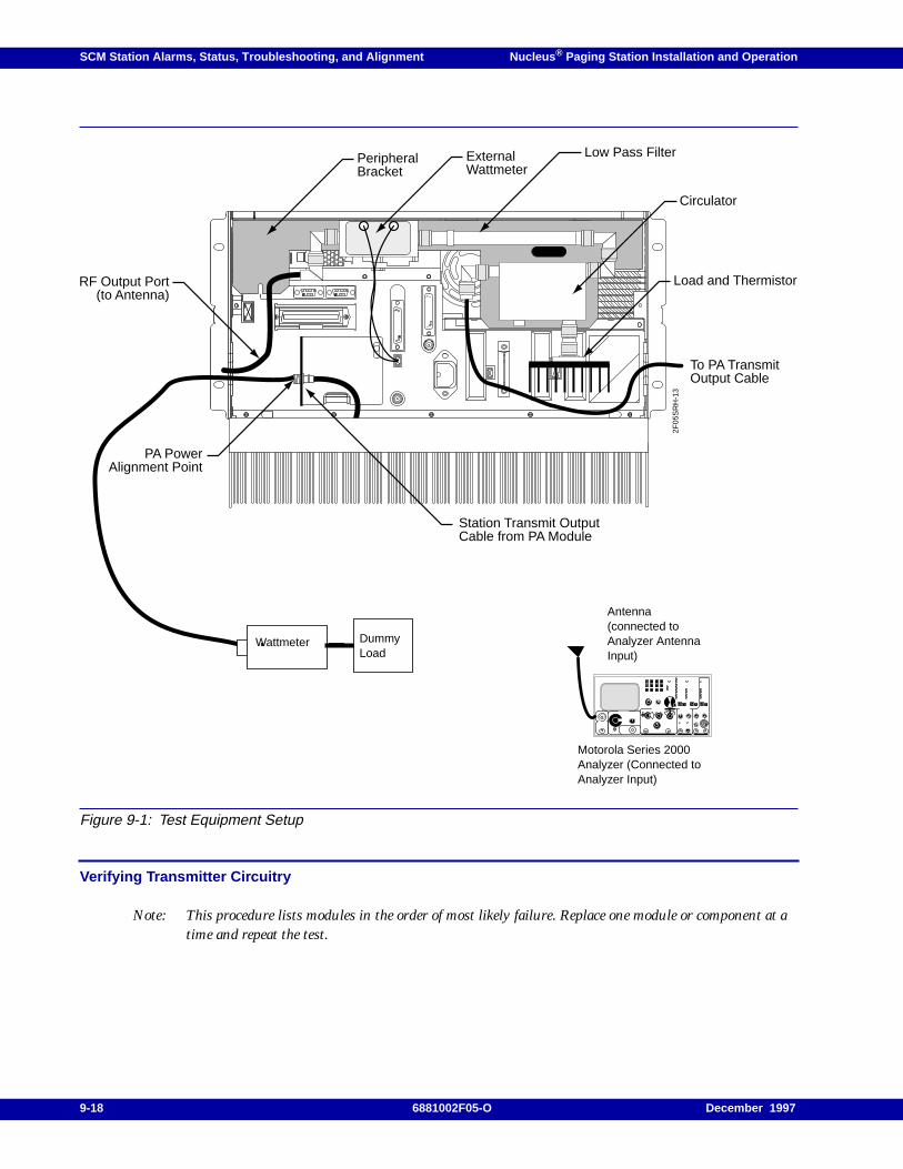
SCM Station Alarms, Status, Troubleshooting, and Alignment Nucleus ® Paging Station Installation and Operation
Figure 9-1: Test Equipment Setup
Verifying Transmitter Circuitry
Note: This procedure lists modules in the order of most likely failure. Replace one module or component at atime and repeat the test.
Motorola Series 2000Analyzer (Connected toAnalyzer Input)
Antenna(connected toAnalyzer AntennaInput)
WattmeterDummyLoad
PeripheralBracket
ExternalWattmeter
Load and Thermistor
Low Pass Filter
Circulator
2F05
SR
H-1
3
RF Output Port(to Antenna)
PA PowerAlignment Point
Station Transmit OutputCable from PA Module
To PA TransmitOutput Cable
DummyLoad
9-18 6881002F05-O December 1997
Nucleus ® Paging Station Installation and Operation SCM Station Alarms, Status, Troubleshooting, and Alignment
Use the following procedure to key with a silent carrier:
Note: Restart and warm up the transmitter after each replacement procedure to determine whether thetransmitter circuitry is functioning correctly.
1. From the READY prompt, press <ALGN>.
The display briefly shows the ALGN menu, then shows the first submenu item.
2. Press <down arrow> to access KEY AND READ POWER.
3. Press <ENT>.
4. Observe the LEDs on the Exciter Module front panel:
a. If the PA Low LED or the PA Fail LED lights, replace or repair the following items in theorder listed.- Improperly calibrated station- Improperly set operating power- PA- SCM and Exciter module- Loose or failed Exciter-to-PA RF cable- Loose or failed PA-to-antenna RF output cable- PA RF output cable termination
b. If the Tx Lock LED is off, replace or return the following items in the order listed.- Frequency not programmed on the current channel- PA- SCM and Exciter module (replace as a matched pair)- Faulty backplane- Hardware mismatch
5. Measure the output power by keying the transmitter with a silent carrier. Observe the display onthe SCM front panel.
6. If the PA is not at the proper power level for the site, adjust the station power output (see Chapter9, "SCM Station Alarms, Status, Troubleshooting, and Alignment").
7. If the PA is at the proper power level for the site, configure the analyzer for spectrum analyzerdisplay.
8. Key the transmitter with silent carrier. From the READY prompt, press <ALGN>. Press<down arrow> to access KEY AND READ POWER and observe the analyzer display. The imageshould have a precise peak (see Figure 9-2).
CAUTION
Turn off the power to replace a module or cable.
Replace the Exciter and SCM only as a matched pair.
December 1997 6881002F05-O 9-19
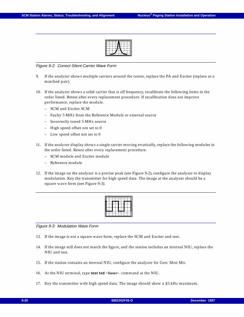
SCM Station Alarms, Status, Troubleshooting, and Alignment Nucleus ® Paging Station Installation and Operation
Figure 9-2: Correct Silent Carrier Wave Form
9. If the analyzer shows multiple carriers around the center, replace the PA and Exciter (replace as amatched pair).
10. If the analyzer shows a solid carrier that is off frequency, recalibrate the following items in theorder listed. Retest after every replacement procedure. If recalibration does not improveperformance, replace the module.
– SCM and Exciter SCM
– Faulty 5 MHz from the Reference Module or external source
– Incorrectly tuned 5 MHz source
– High speed offset not set to 0
– Low speed offset not set to 0
11. If the analyzer display shows a single carrier moving erratically, replace the following modules inthe order listed. Retest after every replacement procedure.
– SCM module and Exciter module
– Reference module
12. If the image on the analyzer is a precise peak (see Figure 9-2), configure the analyzer to displaymodulation. Key the transmitter for high speed data. The image at the analyzer should be asquare wave form (see Figure 9-3).
Figure 9-3: Modulation Wave Form
13. If the image is not a square wave form, replace the SCM and Exciter and test.
14. If the image still does not match the figure, and the station includes an internal NIU, replace theNIU and test.
15. If the station contains an internal NIU, configure the analyzer for Gen/Mon Mtr.
16. At the NIU terminal, type test txd <Enter>. command at the NIU.
17. Key the transmitter with high speed data. The image should show a ±5 kHz maximum.
9-20 6881002F05-O December 1997
Nucleus ® Paging Station Installation and Operation SCM Station Alarms, Status, Troubleshooting, and Alignment
18. If the image is outside this range, replace the SCM and Exciter and test.
If all measurements are now correct, the verification procedure is now complete.
If all measurements are not correct, repeat this procedure from Step 1.
Using the Service Mode
The service mode provides two useful procedures for troubleshooting:
• Select the pattern transmitted by the station.
• Verify proper 4-level messaging alignment.
Note: If the PA test mode is active, the PA keys even if a PA fault exists.
Enable PA Test Mode
The PA test mode allows the transmitter to key even if a PA fault exists. This feature facilitatestroubleshooting.
Note: The normal control circuitry in the Nucleus paging station does not allow the station to remain keyedwith a PA fault for more than 5 min.
Use the following procedure to read the status:
1. From the READY prompt, press <SERV> to access the Service menu.
The display briefly shows the SERV menu, then shows the first submenu item.
2. Press <ENT> to access the PA TEST MODE submenu.
The display shows the current status of the test mode:
PA TEST: INACTIVE
Note: If the PA test mode is enabled, the PA Full LED on the Exciter Module front panel flashes.
3. To enable the test mode, press <ENT>.
The display flashes to show the system is in the edit mode.
4. Press <TOG>.
The display shows the new status of the test mode:
PA TEST: ACTIVE
CAUTION
The station produces hazardous levels of RF power and the tests can damage the PA. The PAtest mode allows the transmitter to key with a PA fault, such as high temperature or highVoltage standing wave ratio (VSWR). The Nucleus paging station does not provide protectivepower reduction. Before using these procedures, reduce transmit power through the TX menuand the TX CHN PWR submenu.
December 1997 6881002F05-O 9-21
SCM Station Alarms, Status, Troubleshooting, and Alignment Nucleus ® Paging Station Installation and Operation
5. Press <ENT>.
The display stops flashing and shows that the test mode is enabled.
6. Press <EXIT> to return to the READY prompt.
7. Disable the PA test mode when testing and repairs are complete.
Select a Test Pattern
The Nucleus paging station supports pattern selection for transmission testing. Use this procedure tochange the pattern:
1. From the READY prompt, press <SERV> to access the Service menu.
The display briefly shows the SERV menu, then shows the first submenu item:
PA TEST MODE: INACTIVE
2. Press <down arrow> to access the SELECT SYMBOL submenu.
SELECT SYMBOL: STAIRCASE
3. Press <ENT>.
The display flashes.
4. Press <down arrow> to select a pattern from the following:
– STAIRCASE (the station transmits the 4-level staircase [10, 11, 01, 00)
– 01–10 (the station transmits 01, 10, 01, 10)
– 00–11 (the station transmits 00, 11, 00, 11)
– 10 (the station transmits 10, 10, 10)
– 11 (the station transmits 11, 11, 11)
– 01 (the station transmits 01, 01, 01)
– 00 (the station transmits 00, 00, 00)
– CARRIER (the station transmits the carrier frequency)
5. Press <ENT>.
The station begins testing.
6. Press <EXIT> to return to the READY prompt.
Key on Symbol
The Nucleus paging station supports testing to verify 4-level messaging alignment (for 4-level FLEXmessaging). Use this procedure to select a pattern the pattern:
1. From the READY prompt, press <SERV> to access the Service menu.
The display briefly shows the SERV menu, then shows the first submenu item.
9-22 6881002F05-O December 1997
Nucleus ® Paging Station Installation and Operation SCM Station Alarms, Status, Troubleshooting, and Alignment
2. Press <up arrow> to access the KEY ON SYMBOL submenu.
3. Press <ENT>.
The display shows the following text:
TRANSMITTING SYMBOL
4. Press <EXIT> once. The station dekeys.
5. Press <EXIT> again to return to the READY prompt.
December 1997 6881002F05-O 9-23
SCM Station Alarms, Status, Troubleshooting, and Alignment Nucleus ® Paging Station Installation and Operation
Alignment
The procedure described in this section aligns and optimizes a standard or high power station.
Note: Use this procedure only if troubleshooting or alarm clearance requires replacement of the Exciter andSCM or the PA.
This procedure applies equally to stations with and without a circulator option. For a station with adouble or triple circulator option, perform this procedure before performing the procedure in paragraph,"External Wattmeter Calibration for Stations with Circulator Options".
Test Equipment and Setup
This procedure requires the following test equipment:
• RF coupler, attenuator, and load
• RF power meter (Hewlett Packard 438 power meter or equivalent with an accuracy of 3.5 percentor better)
Use the following procedure to connect equipment for testing:
1. Connect the RF coupler cable to the Power Amplifier (PA) output alignment point. Connect theRF load to the output of the RF coupler.
2. Connect the attenuator to the RF coupler. Connect the RF power meter to the attenuator.
3. Turn on the Nucleus paging station and allow it to warm up for one hour.
4. From the READY prompt, press <OPT1> to access the Options 1 menu.
The light-emitting diode (LED) display briefly shows the OPT1 menu, then shows the firstsubmenu item.
5. Press <down arrow> to access the EXT CIRCULATOR submenu.
6. If the EXT CIRCULATOR selection is PRESENT, press <ENT>.
The display flashes to show the system has entered the edit mode:
PRESENT
7. Press <TOG>. The display stops flashing and shows the change:
CAUTION
Connect the coupler, attenuator, load, and power meter directly to the PA power alignmentpoint without adapters or intermediate cables. The PA power alignment point has an N-typeconnector.
The mean frequency may not be an approved transmit frequency. Connect the station transmitoutput to a dummy load during this procedure. Do not attach the station transmit output to atransmit antenna.
9-24 6881002F05-O December 1997
Nucleus ® Paging Station Installation and Operation SCM Station Alarms, Status, Troubleshooting, and Alignment
NOT PRESENT
8. Press <EXIT> once to return to the READY prompt.
Calibration for the RF Power Output Level
Note: The station uses the mean frequency in three procedures:- station power output alignment- external wattmeter calibration- UHSO/HSO alignment
Use the following procedure to calibrate the RF power output level:
1. From the READY prompt, press <TX> to access the Transmit menu.
The display briefly shows the TX menu, then shows one of the following:
– The first transmitter channel frequency in a channel mapped system:
CHN n FREQ xxx.xxxx MHz
where xxx.xxxx is the current frequency for the first configured channel.
– The frequency for all channels in a non-channel mapped system:
FREQ xxx.xxxx MHz
where xxx.xxxx is the current frequency.
2. Press <up arrow> once to access the MEAN FREQ submenu.
The display shows the mean frequency value:
MEAN FREQ xxx.xxxx MHz
where xxx.xxxx is the current mean frequency.
3. Record this value.
4. Press <EXIT> to return to the READY prompt.
5. Press <CNFG> to access the Station Configuration menu.
The display briefly shows the CNFG menu, then shows the first submenu item:
MAX PWR xxx W
where xxx is the rated power of the PA.
December 1997 6881002F05-O 9-25
SCM Station Alarms, Status, Troubleshooting, and Alignment Nucleus ® Paging Station Installation and Operation
6. Record this value.
7. Press <EXIT> to return to the READY prompt.
Note: Two procedures follow:- power for a non-channel mapped station- power for a channel mapped stationUse the procedure appropriate to the base station.
Power for a Non-channel Mapped Station
Use the following procedure to align power for a non-channel mapped station:
1. From the READY prompt, press <TX> to access the Transmit menu.
The display briefly shows the TX menu, then shows the first submenu item.
2. Press <down arrow> to access the TX CHN PWR submenu.
3. Press <ENT>.
The display shows the operating power level:
OPERATING PWR xxx W
where xxx is the currently programmed station transmit power.
4. To change the station power, press <ENT>.
The message flashes to show the system has entered the edit mode:
xxx
5. Type a new value for operating power.
6. Press <ENT>.
The message stops flashing and shows the new value:
OPERATING PWR yyy W
where yyy is the newly programmed station transmit power.
7. Press <EXIT> to return to the READY prompt.
Continue with paragraph, "Station Power Calibration" or paragraph, "Automatic Station PowerAlignment".
9-26 6881002F05-O December 1997
Nucleus ® Paging Station Installation and Operation SCM Station Alarms, Status, Troubleshooting, and Alignment
Power for a Channel Mapped Station
Use this procedure to enable channel mapping and set the mean frequency if required:
1. From the READY prompt, press <OPT1> to access the Options 1 menu.
The LED briefly shows the OPT1 menu, then shows the first submenu item.
2. Press <down arrow> to access the TX CHN PWR submenu.
3. Press <ENT>.
The display shows the current configuration for channel mapping:
CHN MAPPED PWR: DISABLED
4. Press <ENT>.
The message flashes to show the system has entered the edit mode:
DISABLED
5. Press <TOG>.
The message flashes the new setting:
ENABLED
6. Press <ENT>.
The message stops flashing and shows the new configuration:
CHN MAPPED PWR: ENABLED
7. Press <EXIT> to return to the READY prompt.
8. Press <TX> to access the Transmit menu.
The display briefly shows the TX menu, then shows the first submenu item.
9. Press <down arrow> to access the TX CHN PWR submenu.
10. Press <ENT>.
The display shows the current power level for the first programmed channel:
CHN n PWR xxx W
where xxx is the currently programmed transmit power for channel n.
11. Press <down arrow> to show the mean frequency power:
MEAN FREQ PWR zzz W
where zzz is the currently programmed power level for the mean frequency.
December 1997 6881002F05-O 9-27
SCM Station Alarms, Status, Troubleshooting, and Alignment Nucleus ® Paging Station Installation and Operation
12. If the mean frequency power is incorrect, press <ENT>.
The message flashes to show the system has entered the edit mode:
zzz
13. Type the correct mean frequency power.
14. Press <ENT>.
The message stops flashing and shows the new mean frequency power:
yyy
where yyy is the newly programmed power level for the mean frequency.
15. Press <EXIT> to return to the READY prompt.
Continue with paragraph, "Station Power Calibration".
Station Power Calibration
Note: If station power output has degraded by more than 5 percent of rated power output, the stationautomatically exits the Alignment menu and dekeys. The PA Low LED lights momentarily. Seeparagraph, "Power for a Non-channel Mapped Station" or paragraph, "Power for a Channel MappedStation" to set the power level before performing this procedure.
Use the following procedure to calibrate station power:
1. From the READY prompt, press <ALGN>.
The display briefly shows ALGN menu, then shows the first submenu item:
CAL STATION POWER
2. Press <ENT>.
The station keys and the Exciter PA Full LED lights.
The display shows the following message:
INITIALIZE CALIBRATION
3. Read the values at the power meter output for an indication of output power.
4. Press <ENT>. The display shows the following message:
INPUT MEASURED PWR
DANGER
Do not use the CALIBRATE submenu. Motorola uses this submenu inmanufacturing. Do not use it in the field.
9-28 6881002F05-O December 1997
Nucleus ® Paging Station Installation and Operation SCM Station Alarms, Status, Troubleshooting, and Alignment
5. Read the power output at the power meter.
6. Type the power output value.
7. Press <ENT>.
8. When the measured power is correct, press <EXIT> once. The station automatically calibrates theinternal Wattmeter and sets the overdrive set point. The display shows the following messages:
INT WM CAL
SET OVER
9. Press <EXIT> to return to the READY prompt.
Automatic Station Power Alignment
This procedure calibrates the RF power output level of the station (measured at the PA power outputalignment point) to within ±5 percent of the programmed value.
1. Detach one of the following (depending on options) from the PA power output alignment point:
– Transmit antenna cable
– External circulator assembly
– Antenna relay module
2. Connect the RF load to the PA output alignment point.
3. At the READY prompt, press <ALGN> to access the Alignment menu. The display briefly showsthe ALGN menu, then shows the first submenu item:
CAL STATION POWER
4. Press <ENT>.
The display shows the Calibration Station Power option:
AUTO PA CALIBRATION
CAUTION
The alignment procedure prevents PA cutbacks by preventing large changes in output power.If the output power is more than 20 percent less than the programmed power level, performStep 5 and type a value that is approximately 20 percent less than the previously programmedvalue. Then, perform Step 1 through Step 4 again.
December 1997 6881002F05-O 9-29
SCM Station Alarms, Status, Troubleshooting, and Alignment Nucleus ® Paging Station Installation and Operation
5. Press <ENT>.
The display shows the prompt to start automatic calibration:
PRESS ENTER TO START
6. Press <ENT>.
The station keys. The station automatically adjusts the output power to reach the programmedpower. The station dekeys.
Note: This procedure takes 20 to 60 seconds.
The display shows the complete prompt:
COMPLETE
7. Detach the RF Load from the PA power output alignment point.
8. Press <EXIT> twice to return to the READY prompt.
If the station has an external Wattmeter, continue with paragraph, "External WattmeterCalibration for Stations with Circulator Options".
Alignment Failure
If the PA cuts back or fails to key during the alignment procedure, the display shows a failuremessage:
ALIGNMENT FAILED!
Correct one or more of the following:
• Check the RF connections from the station to the RF load.
• Run the alignment procedure again, but do not press <EXIT> during the procedure.
• Check the station to determine if one of these conditions exists:
– High Voltage standing wave ratio (VSWR)
– PA overdrive condition
– Low PA supply voltage
– High external circulator temperature
– Antenna relay short
– Battery revert
Completion
Use the following procedure to complete calibration:
1. Press <EXIT> twice. The station dekeys, and the power reading goes to zero.
2. Detach the power meter setup from the PA power output alignment point. Reattach one of thefollowing (depending on options) to the PA power output alignment point:
– Transmit antenna cable
– External circulator assembly
9-30 6881002F05-O December 1997
Nucleus ® Paging Station Installation and Operation SCM Station Alarms, Status, Troubleshooting, and Alignment
– Antenna relay module
If required, continue with the paragraph, "Alignment for an HSO or UHSO Reference".
External Wattmeter Calibration for Stations with Circulator Options
This procedure is required for Nucleus paging stations with double or triple circulator options. Thecirculator options include an external Wattmeter mounted on the peripheral bracket on the rear of thestation. Motorola calibrates the external Wattmeter during calibration. Do not calibrate it unless youreplace the PA module.
Note: Perform the Automatic Station Power Output Calibration procedure before performing the ExternalWattmeter Calibration.
The stand power Nucleus paging station has one circulator option: external double circulator (optionX677).
The high power Nucleus paging station has three circulator options:- external double circulator (option X677)- external triple circulator (option X676)- internal triple circulator (Nucleus paging station model 1105)This procedure applies to the external circulator options.
Use this procedure to calibrate the external Wattmeter on a station with a circulator.
1. At the rear of the station, lift out the peripheral bracket.
2. Detach the transmit antenna cable from the RF output port on the peripheral bracket.
3. Attach the power meter (with coupler, attenuator, and load) to the RF output port.
4. From the READY prompt, press <ALGN> to access the Alignment menu.
The display briefly shows the ALGN menu, then shows the first submenu item.
5. Press <down arrow> to access the CAL EXT WM submenu:
6. Press <ENT>.
The station keys.
The PA Full LED on the Exciter lights.
The display shows the following message:
ENTER POWER MEASUREMENT
7. Read the power level (in Watts) on the power meter and type the value.
8. Press <ENT>.
9. Press <EXIT> to return to the READY prompt. The station rekeys.
December 1997 6881002F05-O 9-31
SCM Station Alarms, Status, Troubleshooting, and Alignment Nucleus ® Paging Station Installation and Operation
10. Detach the power meter from the RF output port on the peripheral bracket. Reattach the transmitantenna cable to the RF output port.
If required, continue with paragraph, "Alignment for an HSO or UHSO Reference".
Alignment for an HSO or UHSO Reference
The Nucleus paging station has two reference options:
• High stability oscillator (HSO)
• Ultra high stability oscillator (UHSO)
Motorola aligns oscillators with a high degree of accuracy during manufacturing. Use this procedurefor periodic maintenance or following the Exciter and SCM replacement.
This section describes two procedures:
• The non-keyed state (using a 5 MHz reference frequency) does not interrupt messaging.
• The keyed state (using the station mean frequency) interrupts messaging.
This procedure adjusts the frequency to within 1 Hz of complete accuracy.
Required Test Equipment
This procedure requires the following test equipment:
• Frequency counter with external rubidium standard–the required accuracy for this equipment isone of the following:
– For HSO, accuracy ≤ 3 ppb
– For UHSO, accuracy ≤ 5 ppb
• RF coupler, attenuator, and load (for keyed state alignment only)
Alignment in the Non-keyed State
This section describes alignment with a 5 MHz reference frequency while the station continues to keyand send messaging.
Use the following procedure to align the reference in the keyed state:
1. Connect a BNC cable to one of the following locations:
– Ref. Freq. port on the Station Control Module (SCM) front panel
– Backplane connector J30
CAUTION
If the station has an internal Network Interface Unit (NIU) and a UHSO or HSO reference,DIP switch 8 position 1 must be switched on.
If the station has an internal NIU and no other reference, DIP switch 8, pole 1, must beswitched off.
In either case, DIP switch 8, pole 2, must be on.
9-32 6881002F05-O December 1997
Nucleus ® Paging Station Installation and Operation SCM Station Alarms, Status, Troubleshooting, and Alignment
From the READY prompt, press <ALGN> to access the Alignment menu.
The display briefly shows the ALGN menu, then shows the first submenu item.
2. Press <down arrow> to access the ALGN UHSO submenu.
3. Press <ENT>.
The display shows the following message:
KEY START
4. Press <down arrow>.
The display shows the following message:
START
5. Press <ENT>.
The station does not key.
The display shows the steering line Voltage (in the range 1 through 4096):
UHSO xxxx
where xxxx is the steering Voltage.
6. Monitor the reference frequency. At the same time, type a new steering Voltage (a value in Volts,in the range 1 to 4096).
7. Press <ENT>.
8. Repeat Step 6 and Step 7 as many times as required to bring the displayed frequency intoagreement with specifications.
9. Press <EXIT> to return to the READY prompt.
Alignment in the Keyed State
Use the following procedure to align a keyed station:
1. Connect the RF cable to the RF coupler.
2. From the READY prompt, press <ALGN> to access the Alignment menu.
The display briefly shows the ALGN menu, then shows the first submenu item.
CAUTION
If the station has an internal Network Interface Unit (NIU) and a UHSO or HSO reference,DIP switch 8 position 1 must be switched on.
If the station has an internal NIU and no other reference, DIP switch 8, pole 1, must beswitched off.
In either case, DIP switch 8, pole 2, must be on.
December 1997 6881002F05-O 9-33
SCM Station Alarms, Status, Troubleshooting, and Alignment Nucleus ® Paging Station Installation and Operation
3. Press <down arrow> to access the ALIGN UHSO submenu.
4. Press <ENT>.
The display shows the following message:
KEY START
5. Press <ENT>.
The station keys.
The display shows the steering line Voltage (in the range 1 through 4096):
HSO xxxx
where xxxx is the steering Voltage.
6. Monitor the reference frequency. At the same time, type a new steering Voltage (a value in Volts,in the range 1 to 4096).
7. Press <ENT>.
8. Repeat Step 6 and Step 7 as many times as necessary to bring the displayed frequency intoagreement with specifications.
9. Press <EXIT> twice to return to the READY prompt.
Alignment Completion
This section describes two procedures (with and without an external Wattmeter) for completing thealignment procedure and verifying operation. Use one of these procedures after completing all otheralignment procedures.
Wattmeter Present
Use the following procedure to measure forward power, reflected power, and Voltage standing waveratio (VSWR) with an external Wattmeter:
Note: The EXT WATTMETER TYPE must be EXT CLASS 1 (from the Configuration menu) and PRESENT(from the Options 1 menu).
1. From the READY prompt, press <ALGN> to access the Alignment menu.
The display briefly shows the ALGN menu, then shows the first submenu item.
2. Press <up arrow> to access the KEY AND READ POWER submenu.
3. Press <ENT>.
4. The station keys with a silent carrier. The display shows the forward power value, the reflectedpower value, and the VSWR sequentially:
FORWARD POWER xxx
REFLECTED POWER yyy
9-34 6881002F05-O December 1997
Nucleus ® Paging Station Installation and Operation SCM Station Alarms, Status, Troubleshooting, and Alignment
VSWR zzz
5. Press <ENT>.
The display shows the forward power value, the reflected power value, and the VSWR measuredat the external Wattmeter sequentially:
EXTERNAL WM FORWARD POWER xxx
EXTERNAL WM REFLECTED POWER yyy
EXTERNAL WM VSWR zzz
6. Press <EXIT> to return to the READY prompt.
Wattmeter Not Present
Use the following procedure to measure forward power, reflected power, and Voltage standing waveratio:
Note: The EXT WATTMETER TYPE must be NONE (from the Configuration menu) and NOT PRESENT(from the Options 1 menu).
1. From the READY prompt, press <ALGN> to access the Alignment menu.
The display briefly shows the ALGN menu, then shows the first submenu item.
2. Press <up arrow> to access the KEY AND READ POWER submenu.
3. Press <ENT>.
The station keys with a silent carrier. The display shows the forward power value, the reflectedpower value, and the VSWR:
FORWARD POWER xxx
REFLECTED POWER yyy
VSWR zzz
4. Press <EXIT> to return to the READY prompt.
December 1997 6881002F05-O 9-35
SCM Station Alarms, Status, Troubleshooting, and Alignment Nucleus ® Paging Station Installation and Operation
Advanced Power Measurements
This section describes advanced power measurement procedures s for 250 W and 300 W Nucleuspaging stations with SCM application version 3.320.
The use of a high power Nucleus paging station in the field has raised some issues regardingoperation and output power alignment. These issues include the following:
• Inconsistencies in measured power
• Compensation for errors associated with measurement techniques or equipment problems
In the past, Nucleus paging stations allowed manual RF power alignment. Manual power alignmenthas a major drawback. It inadvertently compensates for measurement errors: RF power alignment isadjusted until the technician achieved a desired in-line Wattmeter reading at a device–a reading thatmight be very different from the true power level.
The release of the software version 3.21 (or later) introduces automatic power alignment for highpower stations. High power stations with the new software do not allow external manual adjustment.The station now calibrates itself to ensure that output power is always within the station designspecification.
Measurement Issues
Measuring output at a paging station had a number of problems:
• Measuring equipment that is not itself calibrated–such equipment produces errors inmeasurement.
• Rating specification–the power rating for any base station transmitter is specified at one pointonly in the RF output path. If power is measured anywhere else in the RF output path, a readingother than the specified power will result.
• Equipment in the RF path–Circulators, filters, power meters, relays, or cables degrade the RFpower and the validity of the reading.
• Component tolerance limits on accuracy.
• Mismatches between any two items in the RF path.
• Degradation over time.
• Power output adjustments between 100 W and 300 W–the power does not vary in a completelylinear way.
As the signal frequency increases, these errors become more pronounced.
Motorola ships high power PAs as FRUs. This means that all PAs with application software 3.21 orhigher has the same power output accuracy as a new high power station.
9-36 6881002F05-O December 1997
Nucleus ® Paging Station Installation and Operation SCM Station Alarms, Status, Troubleshooting, and Alignment
Automatic Alignment
The high power Nucleus paging station PA contains an internal Wattmeter for that generates TX_VF.The accuracy of this Wattmeter allows Motorola to tun the PA during manufacturing to a high degreeof accuracy. Every PA has the same voltage value for TX_VF when the operating power is 300W. Thesoftware look-up table used by power control is now configured to work with this accuracy. (Thetechnician does not type power values into the Nucleus paging station front panel to adjust this table.)
Auto station power alignment results in maximized PA operating lifetime and minimized thermalstress to the PA. Auto station power alignment also ensures that station self-protection features.
Perform a simple functional check after installing a replacement PA in the system to ensure continuedhigh quality performance.
Decibel Mathematics
In messaging systems, RF power levels can vary quite significantly from transmitter to receiver. Ahigh power Nucleus paging station is rated at as much as 300 Watts of output power while amessaging unit may receive signals at approximately 10 to 13 Watts. We measure these changes usinglogarithmic scales. A logarithmic scale increases or decreases by a factor of 10 and uses only non-zeropositive integers.
A log scale is used compare power or voltage levels. The unit is a deciBel (dB). The definition of thedecibel, abbreviated dB is
dB = 10 * log(P1/P2)
As an example, if P1 = 20W and P2 = 5W, P1 is four times larger than P2. Expressed on a decibel scale,this statement is:
dB = 10 * log(20/5), = 10 * log(4), = 10 * 0.602, = 6.02dB, or = 6dB, the difference between P1 and P2
Unlike watts, volts, and amperes, the dB is not a physical quantity. The dB represents a ratio of twophysical quantities, typically power; and it is itself a dimensionless number much like the units radianand degree which are used to measure plane angles.
Measurements that use log scales to manipulate deciBel values use two rules:
• The product of two pure numbers (or ratios) A and B is equivalent to their sum when the valuesare expressed in dB.
A = 2 (3 dB)
B = 3 (5 dB)
Therefore:
A * B = 2 * 3
3 dB + 5 dB = 6 = 8 dB
• The division of two pure numbers (or ratios) A and B is equivalent to their difference when thevalues are expressed in dB.
A = 4 (6 dB)
B = 2 (3 dB)
December 1997 6881002F05-O 9-37
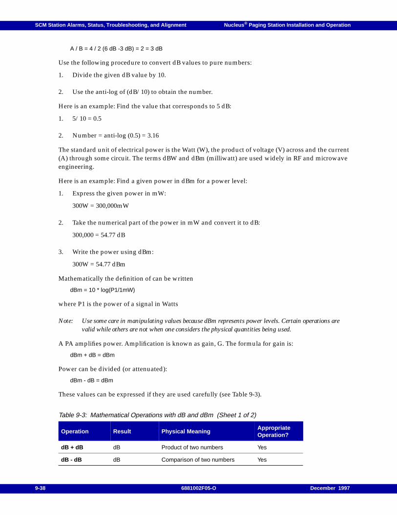
SCM Station Alarms, Status, Troubleshooting, and Alignment Nucleus ® Paging Station Installation and Operation
A / B = 4 / 2 (6 dB -3 dB) = 2 = 3 dB
Use the following procedure to convert dB values to pure numbers:
1. Divide the given dB value by 10.
2. Use the anti-log of (dB/10) to obtain the number.
Here is an example: Find the value that corresponds to 5 dB:
1. 5/10 = 0.5
2. Number = anti-log (0.5) = 3.16
The standard unit of electrical power is the Watt (W), the product of voltage (V) across and the current(A) through some circuit. The terms dBW and dBm (milliwatt) are used widely in RF and microwaveengineering.
Here is an example: Find a given power in dBm for a power level:
1. Express the given power in mW:
300W = 300,000mW
2. Take the numerical part of the power in mW and convert it to dB:
300,000 = 54.77 dB
3. Write the power using dBm:
300W = 54.77 dBm
Mathematically the definition of can be written
dBm = 10 * log(P1/1mW)
where P1 is the power of a signal in Watts
Note: Use some care in manipulating values because dBm represents power levels. Certain operations arevalid while others are not when one considers the physical quantities being used.
A PA amplifies power. Amplification is known as gain, G. The formula for gain is:
dBm + dB = dBm
Power can be divided (or attenuated):
dBm - dB = dBm
These values can be expressed if they are used carefully (see Table 9-3).
Table 9-3: Mathematical Operations with dB and dBm (Sheet 1 of 2)
Operation Result Physical MeaningAppropriateOperation?
dB + dB dB Product of two numbers Yes
dB - dB dB Comparison of two numbers Yes
9-38 6881002F05-O December 1997
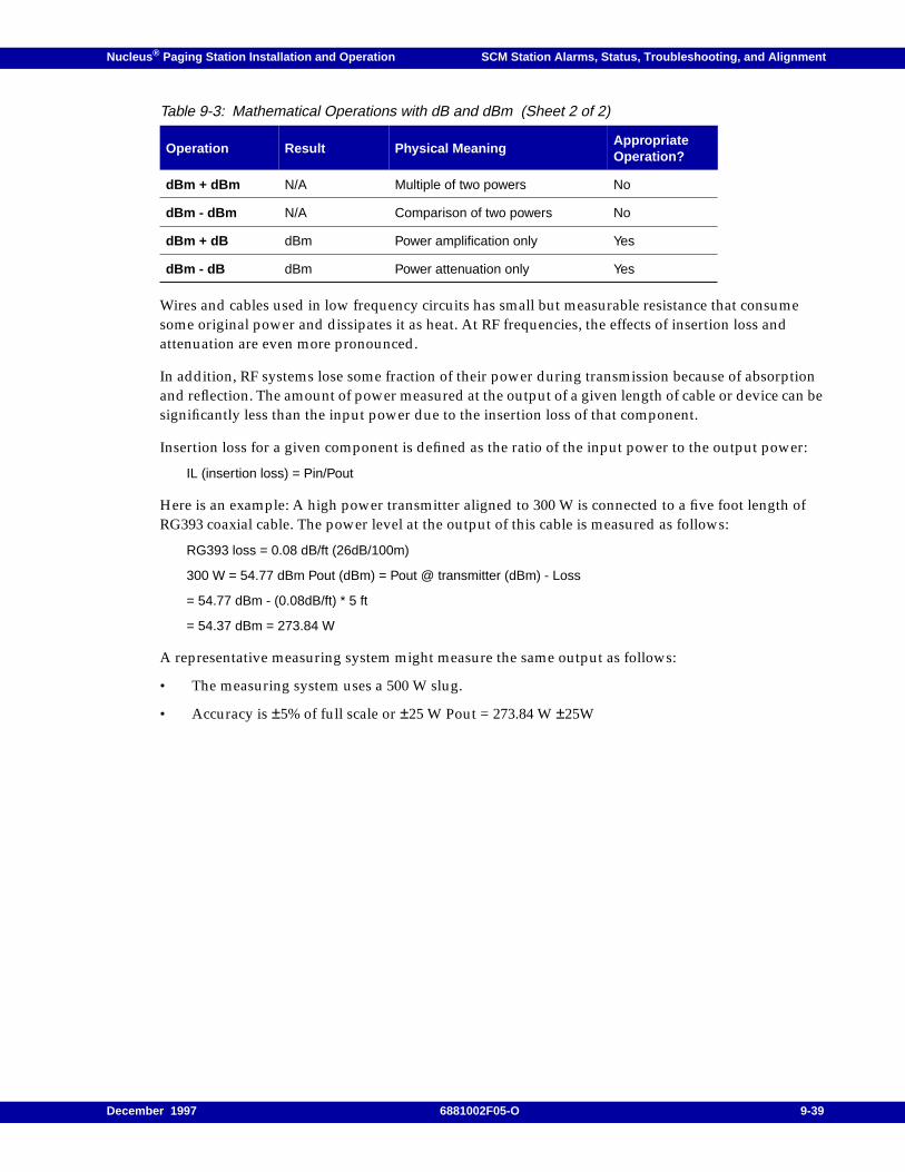
Nucleus ® Paging Station Installation and Operation SCM Station Alarms, Status, Troubleshooting, and Alignment
Wires and cables used in low frequency circuits has small but measurable resistance that consumesome original power and dissipates it as heat. At RF frequencies, the effects of insertion loss andattenuation are even more pronounced.
In addition, RF systems lose some fraction of their power during transmission because of absorptionand reflection. The amount of power measured at the output of a given length of cable or device can besignificantly less than the input power due to the insertion loss of that component.
Insertion loss for a given component is defined as the ratio of the input power to the output power:
IL (insertion loss) = Pin/Pout
Here is an example: A high power transmitter aligned to 300 W is connected to a five foot length ofRG393 coaxial cable. The power level at the output of this cable is measured as follows:
RG393 loss = 0.08 dB/ft (26dB/100m)
300 W = 54.77 dBm Pout (dBm) = Pout @ transmitter (dBm) - Loss
= 54.77 dBm - (0.08dB/ft) * 5 ft
= 54.37 dBm = 273.84 W
A representative measuring system might measure the same output as follows:
• The measuring system uses a 500 W slug.
• Accuracy is ±5% of full scale or ±25 W Pout = 273.84 W ±25W
dBm + dBm N/A Multiple of two powers No
dBm - dBm N/A Comparison of two powers No
dBm + dB dBm Power amplification only Yes
dBm - dB dBm Power attenuation only Yes
Table 9-3: Mathematical Operations with dB and dBm (Sheet 2 of 2)
Operation Result Physical MeaningAppropriateOperation?
December 1997 6881002F05-O 9-39

SCM Station Alarms, Status, Troubleshooting, and Alignment Nucleus ® Paging Station Installation and Operation
9-40 6881002F05-O December 1997
Nucleus ® Paging Station Installation and Operation / Chapter 10
NAC Configuration 10
This chapter describes configuration procedures for a Nucleus paging station with Advanced Control(NAC). The procedures in this chapter are intended for first time installations and reinstallations whena station is reconfigured. This chapter contains the following information:
Station Configuration, 10-2Transmit Frequency Configuration, 10-2Operating Power, 10-4
Control Schemes, 10-6Digital Remote Control (DRC), 10-6Key on External Carrier Detect, 10-9Local Control, 10-10Direct Digital Control, 10-13Binary Communication Control, 10-14
Receivers, 10-17Control Path Configuration, 10-17Internal Link Receiver Frequencies, 10-18Internal Link Receiver Squelch, 10-19Internal Monitor Receiver, 10-21External Monitor Receiver, 10-23
Battery Revert Setup, 10-25
Other Configuration Parameters, 10-27Binary Transmit Data Inversion, 10-27Remote Gain Adjust, 10-27Station Parameters, 10-28
December 1997 6881002F05-O10-1
NAC Configuration Nucleus ® Paging Station Installation and Operation
Station Configuration
This section describes station configuration from the Station menu, the Transmit menu, and theConfiguration menu.
Transmit Frequency Configuration
This section describes two procedures:
• Configuring hardware to enable transmit frequency configuration through software
• Configuring transmit frequency
Hardware Configuration
Use the following procedure to change transmit frequency from the front panel:
1. Turn off the system.
2. Remove the NAC board.
3. Turn DIP switch S300 pole 1 on.
4. Reinstall the NAC board.
5. Turn on the station and allow it to warm up for one hour.
6. Change the frequency (see paragraph, "Transmit Frequency Range").
7. Align the station (see Chapter 11, "NAC Alignment and Equalization", paragraph, "StationAlignment").
8. Turn the station off.
9. Remove the NAC board
10. Turn DIP switch S300 pole 1 off.
11. Reinstall the NAC board.
12. Turn on the station.
Continue with paragraph, "Transmit Frequency Range".
Transmit Frequency Range
The transmit frequency range is a prerequisite to setting the transmit frequency. Use the followingprocedure to configure frequency range:
1. From the READY prompt, press <STN> to access the Station menu.
The display briefly shows the STN menu, then shows the first submenu:
STN TYPE
10-2 6881002F05-O December 1997
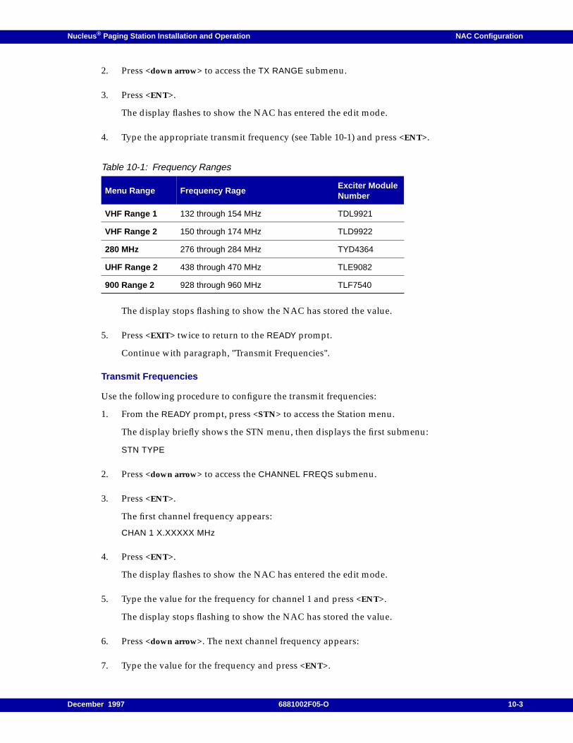
Nucleus ® Paging Station Installation and Operation NAC Configuration
2. Press <down arrow> to access the TX RANGE submenu.
3. Press <ENT>.
The display flashes to show the NAC has entered the edit mode.
4. Type the appropriate transmit frequency (see Table 10-1) and press <ENT>.
The display stops flashing to show the NAC has stored the value.
5. Press <EXIT> twice to return to the READY prompt.
Continue with paragraph, "Transmit Frequencies".
Transmit Frequencies
Use the following procedure to configure the transmit frequencies:
1. From the READY prompt, press <STN> to access the Station menu.
The display briefly shows the STN menu, then displays the first submenu:
STN TYPE
2. Press <down arrow> to access the CHANNEL FREQS submenu.
3. Press <ENT>.
The first channel frequency appears:
CHAN 1 X.XXXXX MHz
4. Press <ENT>.
The display flashes to show the NAC has entered the edit mode.
5. Type the value for the frequency for channel 1 and press <ENT>.
The display stops flashing to show the NAC has stored the value.
6. Press <down arrow>. The next channel frequency appears:
7. Type the value for the frequency and press <ENT>.
Table 10-1: Frequency Ranges
Menu Range Frequency RageExciter ModuleNumber
VHF Range 1 132 through 154 MHz TDL9921
VHF Range 2 150 through 174 MHz TLD9922
280 MHz 276 through 284 MHz TYD4364
UHF Range 2 438 through 470 MHz TLE9082
900 Range 2 928 through 960 MHz TLF7540
December 1997 6881002F05-O 10-3
NAC Configuration Nucleus ® Paging Station Installation and Operation
8. Repeat Step 4 through Step 7 until all channels are programmed.
9. Press <EXIT> twice to return to the READY prompt.
If the receiver uses the same frequency as one of the paging station channels, continue withparagraph, "Enable Tx=Rx". If the receiver does not use the same frequency as one of the pagingstation channels, continue with paragraph, "Operating Power".
Enable Tx=Rx
If a co-located receiver uses a transmit channel for receiving, configure the channel to preventdesensitization of the co-located receiver.
1. From the READY prompt, press <TX> to access the Transmit menu.
The display briefly shows the TX menu, then shows the first submenu:
FREQ ADJUST
2. Press <down arrow> to access the SPECIAL TX SETUP submenu.
3. Press <ENT>.
4. Press <down arrow> to access the TX=RX submenu.
5. Press <ENT>.
The display flashes to show the NAC has entered the edit mode.
6. Press <TOG> to select ENABLED.
7. Press <ENT>.
The display stops flashing to show the NAC has stored the value.
8. Press <EXIT> twice to return to the READY prompt.
Continue with paragraph, "Operating Power".
Operating Power
This procedure configures an operating power level within the allowable output power range for theinstalled PA. Use the following procedure to set this level:
1. From the READY prompt, press <CNFG> to access the Configuration menu.
The display briefly shows the CNFG menu, then shows the first submenu:
OPERATING POWER
2. Press <ENT>.
The display flashes to show the NAC has entered the edit mode and shows the current value.
OPERATING POWER: XXX.X W
Where XXX.X is the current power level.
10-4 6881002F05-O December 1997

Nucleus ® Paging Station Installation and Operation NAC Configuration
3. Type a new value and press <ENT>.
The display stops flashing to show the NAC has stored the value.
4. Press <EXIT> twice to return to the READY prompt.
Continue with paragraph, "Control Schemes".
December 1997 6881002F05-O 10-5
NAC Configuration Nucleus ® Paging Station Installation and Operation
Control Schemes
The Nucleus Advanced Control station supports several control schemes. This section describes thesecontrol schemes and the methods for configuring them. The control schemes comprise the following:
– Digital remote control (DRC) (see paragraph, "Digital Remote Control (DRC)")
– Key on external carrier detect control (see paragraph, "Key on External Carrier Detect")
– Local control (see paragraph, "Local Control")
– Direct digital control (see paragraph, "Direct Digital Control")
– Binary communication control (see paragraph, "Binary Communication Control")
Digital Remote Control (DRC)
Digital Remote Control (DRC) is a Motorola proprietary communication control scheme that uses1200-baud digital signaling (also called MDC-1200) and minimum shift keying (MSK). DRC is aflexible scheme with multi-frequency keying on as many as 4 channels, sector paging on as many as254 sectors, and individual station keying for as many as 1024 stations.
DRC signaling supports information transfer and keying control between the controller and station.DRC employs extensive error detecting and correcting techniques. DRC uses modem tones for 1200and 1800 Hz signaling. This signalling is equally accurate for phone lines and RF.
DRC Data Sets
DRC has two types of data sets, DRC 1 and DRC 2:
• DRC 1 is the communication protocol used by the Digital Diagnostic Controller (DDC), ASC1000, and NAC DRC station s.
• DRC 2 is the enhanced communication protocol used by the ASC 1500 and NAC stations. TheDRC 2 control byte provides more flexibility, more efficient polling, and better equalization,resulting in a higher throughput per hour than DRC 1.
DRC Setup
Use the following procedure to set up DRC.
1. From the READY prompt, press <STN> to access the Station menu.
The display briefly shows the STN menu, then shows the first submenu:
STN TYPE
2. Press <down arrow> to access the STATION CONTROL SETUP submenu.
3. Press <ENT>.
The display shows the DRC SETUP option.
4. Press <ENT>.
The display shows the first item:
DRC ENABLE
10-6 6881002F05-O December 1997
Nucleus ® Paging Station Installation and Operation NAC Configuration
or
DRC DISABLE
5. If DRC is enabled, go to Step 8. If DRC is disabled, press <ENT>.
The display flashes to show the NAC has entered the edit mode.
6. Press <TOG> to select ENABLED .
7. Press <ENT>.
The display stops flashing to show the NAC has stored the value.
DRC is now enabled.
8. Press <EXIT> once to return to the STN menu and the first submenu:
STN TYPE
9. Press <down arrow> to access the STATION CONTROL SETUP submenu.
10. Press <ENT>.
The display shows the DRC SETUP option.
11. Press <ENT>.
The display shows the first item:
DRC ENABLE
12. Press <EXIT> once to return to the STN menu and the first submenu:
STN TYPE
13. Press <down arrow> to access the STATION CONTROL SETUP submenu.
14. Press <ENT>.
The display shows the DRC SETUP option.
15. Press <ENT>.
The display shows the first item:
DRC ENABLE
16. Press <down arrow> to access SYSTEM ID. The display shows one of the following messages:
SYSTEM ID LOCKED
SYSTEM ID UNLOCKED.
17. Press <ENT>.
The display flashes to show the NAC has entered the edit mode.
December 1997 6881002F05-O 10-7
NAC Configuration Nucleus ® Paging Station Installation and Operation
18. Press <TOG> to select LOCKED .
19. Press <ENT>.
The display stops flashing to show the NAC has stored the value.
20. Press <EXIT> once to return to the STN menu and the first submenu:
STN TYPE
21. Press <down arrow> to access the STATION CONTROL SETUP submenu.
22. Press <ENT>.
The display shows the DRC SETUP option.
23. Press <down arrow> to access POLL RESPONSE VIA.
24. Press <ENT>.
The display flashes to show the NAC has entered the edit mode.
25. Press <TOG> to select:
– LINE 2 if the command response route is over the Line 2 audio connection
– RF if the command response is s sent over-the-air on the diagnostics channel
26. Press <ENT>.
The display stops flashing to show the NAC has stored the value.
27. Press <EXIT> once to return to the STN menu and the first submenu:
STN TYPE
28. Press <down arrow> to access the STATION CONTROL SETUP submenu.
29. Press <ENT>.
The display shows the DRC SETUP option.
30. Press <down arrow> to access PAGING KEYUP.
31. If paging keyup is already disabled, go to Step 34. If paging keyup is enabled, press <ENT>.
The display flashes to show the NAC has entered the edit mode.
32. Press <TOG> to select DISABLED .
33. Press <ENT>.
The display stops flashing to show the NAC has stored the value.
34. Press <EXIT> once to return to the STN menu and the first submenu:
STN TYPE
10-8 6881002F05-O December 1997
Nucleus ® Paging Station Installation and Operation NAC Configuration
35. Press <down arrow> to access STN ID (#).
36. Press <ENT>.
The display flashes to show the NAC has entered the edit mode.
37. Type a unique station identification number in the range 1 to 1023. Press <ENT>.
38. Press <ENT>.
The display stops flashing to show the NAC has stored the value.
39. Press <EXIT> twice to return to the READY prompt.
Continue with paragraph, "Receivers".
Key on External Carrier Detect
This procedure configures key on external carrier detect.
Note: The NAC station receives data on J15 pin 3 (External Paging Data) and carrier detect on J15 pin 8(External Carrier Detect).
Use the following procedure to configure key on external carrier detect:
1. From the READY prompt, press <OPT1> to access the Station Options menu.
The display briefly shows the OPT1 menu, then shows the first submenu:
SPECIAL KEY SETUP
2. Press <ENT>.
The display shows the first option:
SPECIAL KEY DISABLED
3. Press <down arrow> to access KEY ON INTERNAL CD.
4. If key on internal CD is disabled, to Step 7. If key on internal CD is enabled, press <ENT>.
The display flashes to show the NAC has entered the edit mode.
5. Press <TOG> to select DISABLE .
6. Press <ENT>.
The display stops flashing to show the NAC has stored the value.
7. Press <EXIT> once to return to the OPT1 menu, and the first submenu:
SPECIAL KEY SETUP
8. Press <down arrow> to access EXTERNAL PAGING DATA SETUP.
9. Press <ENT>.
December 1997 6881002F05-O 10-9
NAC Configuration Nucleus ® Paging Station Installation and Operation
10. Press <down arrow> to access DRC BINARY DATA: INTERNAL / EXTERNAL.
11. If DRC binary data is external, go to Step 14. If DRC binary data is internal, press <ENT>.
The display flashes to show the NAC has entered the edit mode.
12. Press <TOG> to select EXTERNAL .
13. Press <ENT>.
The display stops flashing to show the NAC has stored the value.
14. Press <EXIT> once to return to the OPT1 menu, and the first submenu:
SPECIAL KEY SETUP
15. Press <down arrow> to access WILDCARD CHAN CHANGE.
16. If wildcard chan change is enabled, go to Step 19. If wildcard chan change is disabled, press<ENT>.
The display flashes to show the NAC has entered the edit mode.
17. Press <TOG> to select ENABLE .
18. Press <ENT>.
The display stops flashing to show the NAC has stored the value.
19. Press <EXIT> twice to return to the READY prompt.
Continue with paragraph, "Receivers".
Local Control
Local Control is a standard feature that allows the station to be keyed with the external TTL-levelsignals, External Key Request and External Mode Request. The station receives binary data on theExternal Paging Data line. The station keys when External Key Request goes active. The active level isprogrammable. The station keys analog if External Mode Request is high, and keys binary if ExternalMode Request is low (see Figure 10-1).
10-10 6881002F05-O December 1997
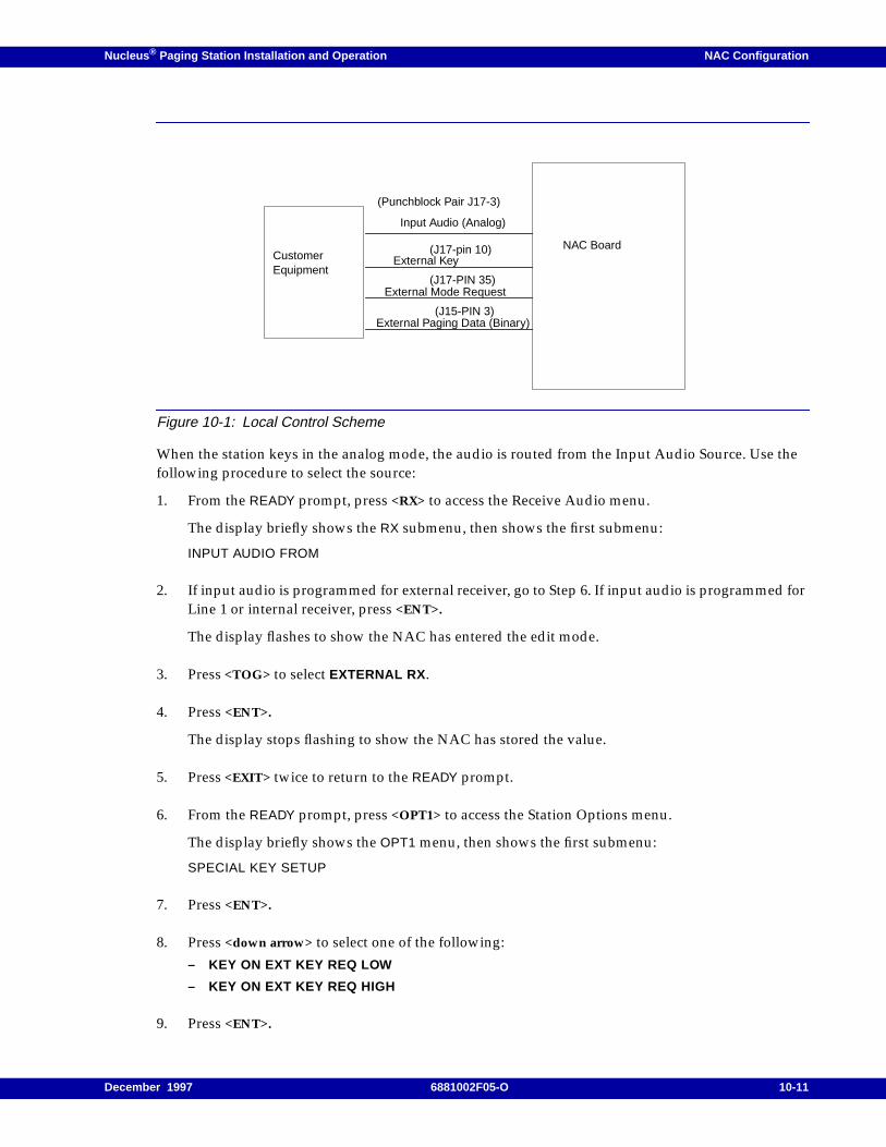
Nucleus ® Paging Station Installation and Operation NAC Configuration
Figure 10-1: Local Control Scheme
When the station keys in the analog mode, the audio is routed from the Input Audio Source. Use thefollowing procedure to select the source:
1. From the READY prompt, press <RX> to access the Receive Audio menu.
The display briefly shows the RX submenu, then shows the first submenu:
INPUT AUDIO FROM
2. If input audio is programmed for external receiver, go to Step 6. If input audio is programmed forLine 1 or internal receiver, press <ENT>.
The display flashes to show the NAC has entered the edit mode.
3. Press <TOG> to select EXTERNAL RX .
4. Press <ENT>.
The display stops flashing to show the NAC has stored the value.
5. Press <EXIT> twice to return to the READY prompt.
6. From the READY prompt, press <OPT1> to access the Station Options menu.
The display briefly shows the OPT1 menu, then shows the first submenu:
SPECIAL KEY SETUP
7. Press <ENT>.
8. Press <down arrow> to select one of the following:
– KEY ON EXT KEY REQ LOW
– KEY ON EXT KEY REQ HIGH
9. Press <ENT>.
CustomerEquipment
External Key
External Mode Request
NAC Board
External Paging Data (Binary)(J15-PIN 3)
(J17-PIN 35)
(J17-pin 10)
Input Audio (Analog)
(Punchblock Pair J17-3)
December 1997 6881002F05-O 10-11
NAC Configuration Nucleus ® Paging Station Installation and Operation
10. Press <EXIT> once to return to the OPT1 menu and the first submenu:
SPECIAL KEY SETUP
Note: Configure input audio for Line 1 if no Link Receiver is present.
11. Press <down arrow> to access EXTERNAL PAGING DATA SETUP.
12. Press <ENT>.
13. Press <down arrow> to access DRC BINARY DATA.
14. If DRC binary data is programmed external, go to Step 17. If DRC binary data is programmedinternal, press <ENT>.
The display flashes to show the NAC has entered the edit mode.
15. Press <TOG> to select EXTERNAL .
16. Press <ENT>.
The display stops flashing to show the NAC has stored the value.
17. Press <EXIT> once to return to the OPT1 menu and the first submenu:
SPECIAL KEY SETUP
18. Press <down arrow> to access EXTERNAL PAGING DATA SETUP.
19. Press <ENT>.
20. Press <down arrow> to access RS232 or EXT MODEM RX DATA.
21. If external paging data setup is programmed for an external modem, go to Step 24. If externalpaging data setup is programmed for RS232, press <ENT>.
The display flashes to show the NAC has entered the edit mode.
22. Press <TOG> to select EXT MODEM RX DATA .
23. Press <ENT>.
The display stops flashing to show the NAC has stored the value.
24. Press <EXIT> once to return to the OPT1 menu and the first submenu:
SPECIAL KEY SETUP
25. Press <down arrow> to access EXTERNAL PAGING DATA SETUP.
26. Press <ENT>.
27. Press <down arrow> to access WILDCARD CHAN CHANGE.
10-12 6881002F05-O December 1997
Nucleus ® Paging Station Installation and Operation NAC Configuration
28. Press <ENT>.
The display flashes to show the NAC has entered the edit mode.
29. Press <TOG> to select ENABLE .
30. Press <ENT>.
The display stops flashing to show the NAC has stored the value.
31. Press <EXIT> twice to return to the READY prompt.
Continue with paragraph, "Receivers".
Direct Digital Control
Direct digital control replaces the typical wireline or RF link path from the ASC to the NAC board witha direct digital link. The direct digital link from the ASC 1500 to the NAC Board may be one of thefollowing:
• Satellite link
• Digital phone network
• Local direct connection
The NAC Board receives digital remote control (DRC) messages through the RS-232 port (connectorJ15 on the station backplane). The station must have DRC enabled for direct digital to operate. TheASC 1500 is required.
Use the following procedure to configure the station for direct digital control:
1. From the READY prompt, press <STN> to access the Station menu.
The display briefly shows the STN menu, then shows the first submenu:
STN TYPE
2. Press <down arrow> to access the STATION CONTROL SETUP submenu.
3. Press <ENT>.
4. The display shows the first option:
DRC SETUP
5. Press <ENT>.
The display shows one of the following:
DRC: ENABLED
DRC: DISABLED
6. If DRC is enabled, go to Step 9. If DRC is disabled, press <ENT>.
The display flashes to show the NAC has entered the edit mode.
December 1997 6881002F05-O 10-13
NAC Configuration Nucleus ® Paging Station Installation and Operation
7. Press <TOG> to select ENABLED .
8. Press <ENT>.
The display stops flashing to show the NAC has stored the data.
9. Press <EXIT> twice to return to the READY prompt.
10. From the READY prompt, press <OPT 1> to access the Stations Options menu.
The display briefly shows the OPT1 menu, then shows the first submenu:
SPECIAL KEY SETUP
11. Press <down arrow> to access EXTERNAL PAGING DATA SETUP.
12. Press <ENT>.
13. Press <down arrow> to access DIRECT DIGITAL.
14. If direct digital is enabled, go to Step 17. If direct digital is disabled, press <ENT>.
The display flashes to show the NAC has entered the edit mode.
15. Press <TOG> to select ENABLED.
16. Press <ENT>.
The display stops flashing to show the NAC has stored the value.
17. Press <EXIT> twice to return to the READY prompt.
Continue with paragraph, "Receivers".
Binary Communication Control
Binary communication control is an external digital control path that uses binary data for controlmessages. Use the following procedure to create a binary communication control path:
1. From the READY prompt, press <OPT 1> to access the Stations Options menu.
The display briefly shows the OPT1 menu, then shows the first submenu:
SPECIAL KEY SETUP
2. Press <down arrow> to access EXTERNAL PAGING DATA SETUP.
3. Press <ENT>.
The display shows the first option:
DELAY ANALOG
or
DIGITAL PATH
10-14 6881002F05-O December 1997
Nucleus ® Paging Station Installation and Operation NAC Configuration
4. If the external paging data path is programmed for a digital path, to Step 7. If the external pagingdata path is delay analog, press <ENT>.
The display flashes to show the NAC has entered the edit mode.
5. Press <TOG> to select DIGITAL PATH .
6. Press <ENT>.
The display stops flashing to show the NAC has stored the value.
7. Press <EXIT> once to return to the OPT1 menu and the SPECIAL KEY SETUP submenu.
8. Press <down arrow> to access EXTERNAL PAGING DATA SETUP.
9. Press <ENT>.
The display shows the first option:
DIGITAL PATH
10. Press <down arrow> to access DRC BINARY DATA.
11. If DRC binary data is programmed for an external source, go to Step 14. If DRC binary data isprogrammed for an internal source, press <ENT>.
The display flashes to show the NAC has entered the edit mode.
12. Press <TOG> to select EXTERNAL .
13. Press <ENT>.
The display stops flashing to show the NAC has stored the value.
14. Press <EXIT> once to return to the OPT1 menu and the SPECIAL KEY SETUP submenu.
15. Press <down arrow> to access EXTERNAL PAGING DATA SETUP.
16. Press <ENT>.
17. Press <down arrow> to access one of the following.
RS232
or
EXTERNAL MODEM RX DATA.
18. If the display shows EXTERNAL MODEM RX DATA, go to Step 21. If the display shows RS232,press <ENT>.
The display flashes to show the NAC has entered the edit mode.
19. Press <TOG> to select EXTERNAL MODEM RX DATA.
December 1997 6881002F05-O 10-15

NAC Configuration Nucleus ® Paging Station Installation and Operation
20. Press <ENT>.
The display stops flashing to show the NAC has stored the value.
21. Press <EXIT> twice to return to the READY prompt.
Continue with paragraph, "Receivers".
10-16 6881002F05-O December 1997
Nucleus ® Paging Station Installation and Operation NAC Configuration
Receivers
Note: Before programming an External Rx 1 input verify that the ASC is connected to J19 on the NACbackplane.
The NAC board requires that the External Paging Carrier Detect signal is active when paging data ispresent. If this signal is not active the station dekeys after the dropout delay time expires. If the externaldevice does not provide External Paging Carrier Detect, connect pin 8 (Ext Paging CD) to pin 9 (A+)on connector J19. External Paging Carrier Detect is active when input voltage is greater than +3 V andinactive when input voltage is less than -3 V. The state is indeterminate when input voltage is between-3 V and +3 V.
The control path is from the controller to the station through a receiver. The NAC station accepts threetypes of control path inputs:
• Input audio from line 1–This selection identifies wireline tones transmitted across a dedicatedphone line to the station as the control tones.
• Input audio from an internal receiver–This selection identifies the internal receiver module,connected to the Control Receiver Interface Board (CRIB). The Internal Rx control path configuresthe station to use RF data received by the internal Receiver Module.
• Input audio from an external receiver–This select identifies the external receiver. Wide-areasystems use external receiver connections, such as a satellite receiver for external modems, foranalog signaling to the station.
This section describes procedures for configuring the following receiver characteristics:
• Internal link receiver frequencies (see paragraph, "Internal Link Receiver Frequencies")
• Internal link receiver squelch (see paragraph, "Internal Link Receiver Squelch")
• Internal monitor receiver (see paragraph, "Internal Monitor Receiver")
• External monitor receiver (see paragraph, "External Monitor Receiver")
Control Path Configuration
Use the following procedure to configure the station for the control path input:
1. From the READY prompt, press <RX> to access the Receiver menu.
The display briefly shows the RX menu, then shows the first submenu:
INPUT AUDIO FROM
2. Press <down arrow> to access INTERNAL RX SETUP.
3. Press <ENT>.
4. Press <down arrow> to access RX FREQ. XXX.XXXX MHZ.
Where XXX.XXXX is the current receiver frequency.
5. Press <ENT>.
December 1997 6881002F05-O 10-17
NAC Configuration Nucleus ® Paging Station Installation and Operation
The display flashes to show the NAC has entered the edit mode.
6. Press <TOG> to select one of the following:
– LINE 1 for input from Line 1
– INTERNAL RX for input from an internal receiver
– EXTERNAL RX 1 for input from an external receiver
7. Press <ENT>.
The display stops flashing to show the NAC has stored the data.
8. Press <EXIT> twice to return to the READY prompt.
Continue with one of the following, depending on the configuration:
– Internal link receiver frequencies (see paragraph, "Internal Link Receiver Frequencies")
– Internal link receiver squelch (see paragraph, "Internal Link Receiver Squelch")
– Internal monitor receiver (see paragraph, "Internal Monitor Receiver")
– External monitor receiver (see paragraph, "External Monitor Receiver")
Internal Link Receiver Frequencies
Use the following procedure to configure the internal receiver module as a link receiver:
1. From the READY prompt, press <RX> to access the Receiver menu.
The display briefly shows the RX menu, then shows the first submenu:
INPUT AUDIO FROM
2. Press <down arrow> to access the RX CHAN SPACING submenu.
3. Press <ENT>.
The display flashes to show the NAC has entered the edit mode.
4. Press <TOG> to select one of the following values:
– 12.5 KHZ
– 25 KHZ
5. Press <ENT>.
The display stops flashing to show the NAC has stored the data.
6. Press <EXIT> twice to return to the READY prompt.
Continue with paragraph, "Internal Link Receiver Squelch".
10-18 6881002F05-O December 1997
Nucleus ® Paging Station Installation and Operation NAC Configuration
Internal Link Receiver Squelch
A NAC link receiver has two modes of squelch control:
• Carrier squelch–The receiver unsquelches when the receiver detects a a carrier signal on theprogrammed internal receiver frequency.
• Digital private line (DPL) squelch–The receiver unsquelches when the receiver detects theprogrammed internal receiver frequency, and the modulated DPL code.
Use the following procedure to modify the squelch operation of the internal receiver:
1. From the READY prompt, press <RX> to access the Receive Audio menu.
The display briefly shows the RX menu, then shows the first submenu:
INPUT AUDIO FROM
2. Press <down arrow> to access INTERNAL RX SETUP.
3. Press <ENT>.
4. Press <down arrow> to access SQUELCH TYPE.
5. Press <ENT>.
The display flashes to show the NAC has entered the edit mode.
6. Press <TOG> to select the appropriate squelch type for the system:
– CARRIER
– DPL
7. Press <ENT>.
The display stops flashing to show the NAC has stored the data.
8. Press <down arrow> to access SQUELCH MODE.
9. Press <ENT>.
The display flashes to show the NAC has entered the edit mode.
10. Press <TOG> to select NORMAL .
11. Press <ENT>.
The display stops flashing to show the NAC has stored the data.
12. Press <down arrow> to access DPL.
13. Press <ENT>.
The display flashes to show the NAC has entered the edit mode.
December 1997 6881002F05-O 10-19
NAC Configuration Nucleus ® Paging Station Installation and Operation
14. Press <TOG> to select the appropriate DPL squelch type for the system:
– ENABLED for DPL as the squelch type
– DISABLED to override the squelch type and make the station unsquelch on carrier detect
15. Press <ENT>.
The display stops flashing to show the NAC has stored the data.
16. Press <down arrow> to access INVERT RX DPL.
17. Press <ENT>.
The display flashes to show the NAC has entered the edit mode.
18. Press <TOG> to select one of the following:
– ENABLED to receive inverted data
– DISABLED to receive non-inverted data
19. Press <ENT>.
The display stops flashing to show the NAC has stored the data.
20. Press <down arrow> to access DPL CODE.
21. Press <ENT>.
The display flashes to show the NAC has entered the edit mode.
22. Press <TOG> to select one of the following:
– ENABLED if the squelch type is DPL and DPL is enabled
– DISABLED if the station unsquelches for the programmed DPL code
23. Press <ENT>.
The display stops flashing to show the NAC has stored the data.
24. Press <down arrow> to access DPL HIGH PASS FILTER.
25. Press <ENT>.
The display flashes to show the NAC has entered the edit mode.
26. Press <TOG> to select ENABLED .
27. Press <ENT>.
The display stops flashing to show the NAC has stored the data.
28. Press <EXIT> twice to return to the READY prompt.
Continue with paragraph, "Battery Revert Setup" or paragraph, "Other ConfigurationParameters".
10-20 6881002F05-O December 1997
Nucleus ® Paging Station Installation and Operation NAC Configuration
Internal Monitor Receiver
Use the following procedure to configure an internal receiver module as a monitor receiver:
1. From the READY prompt, press <RX> to access the Receive Audio menu.
The display briefly shows the RX menu, then shows the first submenu:
INPUT AUDIO FROM
2. Press <down arrow> to access the INTERNAL RX SETUP submenu.
3. Press <ENT>.
4. Press <down arrow> to access LINE 2 AUDIO FROM.
5. Press <ENT>.
The display flashes to show the NAC has entered the edit mode.
6. Press <TOG> to select INT RX.
7. Press <ENT>.
The display stops flashing to show the NAC has stored the data.
8. Press <up arrow> to access MONITOR RX.
9. If the monitor receiver is enabled, go to Step 12. If the monitor receiver is disabled, press <ENT>.
The display flashes to show the NAC has entered the edit mode.
10. Press <TOG> to select ENABLED .
11. Press <ENT>.
The display stops flashing to show the NAC has stored the data.
12. Press <down arrow> to access MONITOR RX SETUP.
13. Press <ENT>.
The display flashes to show the NAC has entered the edit mode.
14. Press <TOG> to select one of the following:
– ANALOG if the system sends analog signals
– TTL if the system sends TTL signals
15. Press <ENT>.
The display stops flashing to show the NAC has stored the data.
16. Press <down arrow> to access RX FREQ: XXX.XXXX MHZ.
December 1997 6881002F05-O 10-21
NAC Configuration Nucleus ® Paging Station Installation and Operation
17. Press <ENT>.
The display flashes to show the NAC has entered the edit mode.
18. Type the receiver frequency value. Type additional zeros to ensure the decimal is in the correctposition.
19. Press <ENT>.
The display stops flashing to show the NAC has stored the data.
20. Press <down arrow> to access RX CHAN SPACING.
21. Press <ENT>.
The display flashes to show the NAC has entered the edit mode.
22. Press <TOG> to select one of the following values:
– 12.5 KHZ
– 25 KHZ
23. Press <ENT>.
The display stops flashing to show the NAC has stored the data.
24. Press <down arrow> to access STATUS TONE.
25. If the tone is enabled, go to Step 28. If the tone is disabled, press <ENT>.
The display flashes to show the NAC has entered the edit mode.
26. Press <TOG> to select ENABLED .
27. Press <ENT>.
The display stops flashing to show the NAC has stored the data.
Note: The default Status Tone Frequency is 2175 Hz, a level that is correct for most stations. If it is necessaryto change the frequency or the level of the status tone, perform Step 28 through Step 34.
28. Press <down arrow> to access STATUS TONE FREQ.
29. Press <ENT>.
The display flashes to show the NAC has entered the edit mode.
30. Type the frequency value in the range 300 to 3000 Hz and press <ENT>.
The display stops flashing to show the NAC has stored the data.
Note: The default setting for the status tone level is -13 dB relative to a received tone at 60% of full systemdeviation.
31. Press <down arrow> to access STATUS TONE LEVEL.
10-22 6881002F05-O December 1997
Nucleus ® Paging Station Installation and Operation NAC Configuration
32. Press <ENT>.
The display flashes to show the NAC has entered the edit mode.
33. Press <TOG> (to provide a negative value) and type a value in the range 7.0 to 19.0 dB.
34. Press <ENT>.
The display stops flashing to show the NAC has stored the data.
35. Press <EXIT> to return to the RX menu and the INPUT AUDIO FROM submenu.
36. Press <down arrow> to access the LINE 2 AUDIO FROM submenu.
37. If the line 2 audio source is internal receiver, continue to Step 40. If the line 2 audio source isprogrammed Line 1 or external receiver, press <ENT>.
The display flashes to show the NAC has entered the edit mode.
38. Press <TOG> to select INT RX.
39. Press <ENT>.
The display stops flashing to show the NAC has stored the data.
Note: If the monitor receiver is tuned to the same frequency as the paging station the station may sufferdesensitization problems. Configure TX>SPECIAL Tx SETUP>Tx=Rx: ENABLED.
40. Press <EXIT> twice to return to the READY prompt.
Note: Perform line 2 output level adjust (see Chapter 11, "NAC Alignment and Equalization", paragraph,"Line 2 Output Level Adjust". Also perform internal receiver squelch threshold alignment (see Chapter11, "NAC Alignment and Equalization", paragraph, "Internal Receiver Squelch ThresholdAdjustment"). In addition perform an internal receiver test tone procedure (see Chapter 11, "NACAlignment and Equalization", paragraph, "Internal RX Test Tone").
Continue with paragraph, "Battery Revert Setup" or paragraph, "Other ConfigurationParameters".
External Monitor Receiver
Use the following procedure to configure the station for use with an External Monitor Receiver:
1. From the READY prompt, press <RX> to access the Receive Audio menu.
The display briefly shows the RX menu, then shows the first submenu:
INPUT AUDIO FROM.
2. Press <down arrow> to access the EXTERNAL RX SETUP submenu.
3. Press <ENT>.
December 1997 6881002F05-O 10-23
NAC Configuration Nucleus ® Paging Station Installation and Operation
4. Press <down arrow> to access MONITOR RX.
5. If the monitor receiver is enabled, go to Step 8. If the monitor receiver is disabled, press <ENT>.
The display flashes to show the NAC has entered the edit mode.
6. Press <TOG> to select ENABLED .
7. Press <ENT>.
The display stops flashing to show the NAC has stored the data.
8. Press <EXIT> to return to the RX menu.
9. If the line 2 source is configured for external receiver 2, go to Step 13. If the line 2 source is internalreceiver or none, press <down arrow> to access the LINE 2 AUDIO FROM submenu.
10. Press <ENT>.
The display flashes to show the NAC has entered the edit mode.
11. Press <TOG> to select EXT RX 2.
12. Press <ENT>.
The display stops flashing to show the NAC has stored the data.
13. Press <EXIT> to return to the RECEIVE AUDIO menu.
14. Press <down arrow> to access the LINE 2 AUDIO submenu.
15. Press <ENT>.
The display flashes to show the NAC has entered the edit mode.
16. Press <TOG> to select one of the following values:
– FLAT
– DEEMPHASIS
17. Press <ENT>.
The display stops flashing to show the NAC has stored the data.
Note: If the monitor receiver is tuned to the same frequency as the paging station, the station may sufferdesensitization problems. Configure TX>SPECIAL TX SETUP>TX=RX: ENABLED.
18. Press <EXIT> twice to return to the READY prompt.
Note: Perform line 2 output level adjust (see Chapter 11, "NAC Alignment and Equalization", Chapter ,"Line 2 Output Level Adjust").
Continue with paragraph, "Battery Revert Setup" or paragraph, "Other ConfigurationParameters".
10-24 6881002F05-O December 1997
Nucleus ® Paging Station Installation and Operation NAC Configuration
Battery Revert Setup
Battery revert provides power if the AC power fails. Motorola offers two battery revert options, X30and X43 (see Chapter 5, "Connectors and Interfaces", paragraph, "Battery Revert Setup").
Use the following procedure to verify battery revert:
1. From the READY prompt, press <CNFG> to access the Station Configuration menu.
The display briefly shows the CNFG menu, then shows the first submenu:
OPERATING PWR
2. Press <down arrow> to access the BATTERY REVERT SETUP submenu.
3. Press <ENT>.
4. Press <down arrow> to access the BATTERY REVERT option and the current value.
5. If the value is SEALED LEAD CALCIUM, go to Step 8. If the value is NONE, and battery revert isinstalled, press <ENT>.
The display flashes to show the NAC has entered the edit mode.
6. Press <TOG> to select SEALED LEAD CALCIUM .
7. Press <ENT>.
The display stops flashing to show the NAC has stored the data.
8. Press <down arrow> to access BACKUP.
9. Press <ENT>.
The display flashes to show the NAC has entered the edit mode.
10. Press <TOG> to select one of the following:
– STATION for use with option X43–the station continues to key during battery revert (performStep 12 through Step 14).
– CONTROL for use with option X30–the station stops keying during battery revert
11. Press <ENT>.
The display stops flashing to show the NAC has stored the data.
12. Press <down arrow> to access FIXED CUTBK RED %.
13. Press <ENT>.
The display flashes to show the NAC has entered the edit mode.
14. Type a value that represents the percentage of power that the station will cut during paging whena battery revert occurs. Press <ENT>.
December 1997 6881002F05-O 10-25

NAC Configuration Nucleus ® Paging Station Installation and Operation
The display stops flashing to show the NAC has stored the data.
15. Press <EXIT> twice to return to the READY prompt.
Continue with paragraph, "Other Configuration Parameters".
10-26 6881002F05-O December 1997
Nucleus ® Paging Station Installation and Operation NAC Configuration
Other Configuration Parameters
The procedures described in this section are for two special applications:
• Binary transmit data inversion (see paragraph, "Binary Transmit Data Inversion")
• Remote gain adjust (see paragraph, "Remote Gain Adjust")
• Station parameters (see paragraph, "Station Parameters")
Binary Transmit Data Inversion
Binary transmit data inversion inverts the transmitted data. Use the following procedure to enabledata inversion:
1. From the READY prompt, press <TX> to access the Transmit menu.
The display briefly shows the TX menu, then shows the first submenu:
FREQ ADJUST
2. Press <down arrow> to access the SPECIAL TX SETUP submenu.
3. Press <ENT>.
4. Press <down arrow> to access the BINARY TX DATA INVERT option.
5. If data inversion is already enabled, go to Step 8. If data is not inverted, press <ENT>.
The display flashes to show the NAC has entered the edit mode.
6. Press <TOG> to select ENABLED .
7. Press <ENT>.
The display stops flashing to show the NAC has stored the data.
8. Press <EXIT> to return to the READY prompt.
Remote Gain Adjust
If remote gain adjust is enabled, the ASC remotely adjusts the station analog gain to compensate forchanges in control path attenuation that affect the station output analog deviation.
Note: This feature requires DRC.
Use the following procedure to enable remote gain adjust:
1. From the READY prompt, press <RX> to access the Receive Audio menu.
The display briefly shows the RX menu, then shows the first submenu:
INPUT AUDIO FROM.
2. Press <down arrow> to access the GAIN submenu. The display shows one of the following:
December 1997 6881002F05-O 10-27
NAC Configuration Nucleus ® Paging Station Installation and Operation
GAIN: ENABLED
or
GAIN: DISABLED
3. If gain is already enabled, go to Step 6. If gain is disabled, press <ENT>.
The display flashes to show the NAC has entered the edit mode.
4. Press <TOG> to select ENABLED .
5. Press <ENT>.
The display stops flashing to show the NAC has stored the data.
6. Press <down arrow> to access the GAIN (value) submenu.
7. Press <ENT>.
The display flashes to show the NAC has entered the edit mode.
8. Type a value for the gain in the range -10 dB to +10 dB (0.1 dB increments) and press <ENT>.
The display stops flashing to show the NAC has stored the data.
9. Press <EXIT> twice to return to the READY prompt.
Station Parameters
The procedures described in this section are specific to an individual station. These values include thefollowing:
• Drop-out delay
• Key time-out
• System timer alarm
Use the following procedure to set these values if required:
1. From the READY prompt, press <STN> to access the Station menu.
The system briefly shows the STN menu, then shows the first submenu:
STN TYPE
2. Press <down arrow> to access the DROP OUT DELAY submenu. The drop out delay is a periodafter the end of paging of control data when the station remains keyed.
Note: The default value for a DRC station is 6 seconds.
3. Press <ENT>.
The display flashes to show the NAC has entered the edit mode.
10-28 6881002F05-O December 1997
Nucleus ® Paging Station Installation and Operation NAC Configuration
4. Press <TOG> to select a drop out value. and press <ENT>.
The display stops flashing to show the NAC has stored the data.
5. Press <down arrow> to access the KEY TIMEOUT submenu. The key time out value is themaximum time the station can remain keyed.
6. Press <ENT>.
The display flashes to show the NAC has entered the edit mode.
7. Type a value or press <TOG> to select DISABLED .
8. Press <ENT>.
The display stops flashing to show the NAC has stored the data.
9. Press <down arrow> to access the SYSTEM TIMER ALARM submenu. The system timer alarmvalue is the maximum length of idle time before the station declares an alarm.
10. Type a value or press <TOG> to select DISABLED .
11. Press <ENT>.
The display stops flashing to show the NAC has stored the data.
Note: This parameter sets the value. The ASC enables the alarm.
12. Press <EXIT> twice to return to the READY prompt.
December 1997 6881002F05-O 10-29

NAC Configuration Nucleus ® Paging Station Installation and Operation
10-30 6881002F05-O December 1997

Nucleus ® Paging Station Installation and Operation / Chapter 11
NAC Alignment and Equalization 11
This chapter describes three post-installation procedures that maximize the performance of a Nucleuspaging station with Advanced Control (NAC). This chapter contains the following information:
Station Alignment, 11-2Test Equipment, 11-2Preliminary Checks, 11-2Connecting Test Equipment, 11-3Internal Receiver Squelch Threshold Adjustment, 11-4External Link Receiver Audio Adjust, 11-4Input Gain Adjust, 11-6
Frequency and Power Configuration, 11-8Manual Station Power Output Calibration, 11-9Automatic Station Power Output Calibration, 11-11External Wattmeter Calibration, 11-12Reference Alignment, 11-14VCO Modulation Sensitivity Calibration, 11-16Analog Deviation Verification, 11-17Transmit Audio Response, 11-18Binary Splatter Filter, 11-18SRM Alignment, 11-19Line 2 Output Level Adjust, 11-21Binary Deviation Values, 11-23Internal RX Test Tone, 11-23Alignment Completion, 11-24
Simulcast Equalization, 11-25Simulcast Operation, 11-25Automatic Delay, 11-25Station Configuration for Automatic Delay Equalization, 11-27Analog Equalization Setup, 11-28
Remote Carrier Frequency Adjust, 11-30
December 1997 6881002F05-O 11-1
NAC Alignment and Equalization Nucleus ® Paging Station Installation and Operation
Station Alignment
This section describes station alignment. Motorola aligns a stations during manufacturing, with theexception of input gain adjust (specific to the network) and internal receiver squelch thresholdadjustment. Perform alignment only after replacement of a field replaceable unit (FRUs) or a change inchannel information.
Test Equipment
Note: Tune station output attenuation to less than 0.25 W before applying to HP 53310A ModulationDomain Analyzer.
This procedure requires the following items of test equipment:
• R2000 Series Service Monitor, or equivalent
• High stability oscillator, Ball Efratom, Model PRFS (or equivalent)
• RF load with coupler and attenuator
• RF power Wattmeter (capable of handling maximum station output power)
• Frequency counter with accuracy 0.1 ppb or better
• HP 53310A Modulation Domain Analyzer
Preliminary Checks
Perform all the following preliminary checks on the NAC station before beginning alignment:
1. Verify that all boards are securely installed against the backplane and are connected to the framewith their mounting screws.
2. Verify that all backplane connectors are correct and secure.
3. Turn on the station and allow it to warm up for one hour. The ON LED on each power supplymust light.
4. Verify that station RF output is properly loaded in a 50-ohm load capable of absorbing themaximum station output power.
Perform all the following procedure:
1. Press <STN> and <TX> to reset the station.
All LEDs light on the front panels.
The display shows the following message:
CAUTION
Do not perform the procedures described in this section unless you have a thoroughknowledge of NAC operation. Read all test equipment manuals before beginning theseprocedures.
11-2 6881002F05-O December 1997
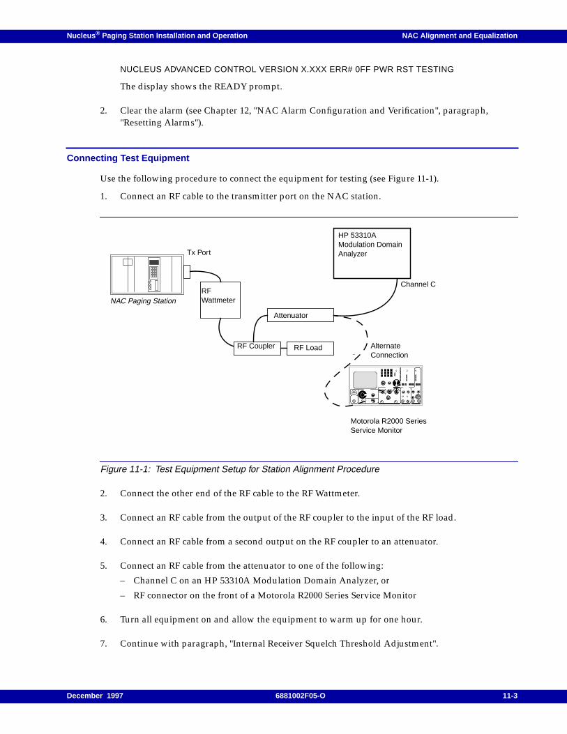
Nucleus ® Paging Station Installation and Operation NAC Alignment and Equalization
NUCLEUS ADVANCED CONTROL VERSION X.XXX ERR# 0FF PWR RST TESTING
The display shows the READY prompt.
2. Clear the alarm (see Chapter 12, "NAC Alarm Configuration and Verification", paragraph,"Resetting Alarms").
Connecting Test Equipment
Use the following procedure to connect the equipment for testing (see Figure 11-1).
1. Connect an RF cable to the transmitter port on the NAC station.
Figure 11-1: Test Equipment Setup for Station Alignment Procedure
2. Connect the other end of the RF cable to the RF Wattmeter.
3. Connect an RF cable from the output of the RF coupler to the input of the RF load.
4. Connect an RF cable from a second output on the RF coupler to an attenuator.
5. Connect an RF cable from the attenuator to one of the following:
– Channel C on an HP 53310A Modulation Domain Analyzer, or
– RF connector on the front of a Motorola R2000 Series Service Monitor
6. Turn all equipment on and allow the equipment to warm up for one hour.
7. Continue with paragraph, "Internal Receiver Squelch Threshold Adjustment".
NAC Paging Station
Tx Port
Motorola R2000 SeriesService Monitor
Channel C
HP 53310AModulation DomainAnalyzer
AlternateConnection
RFWattmeter
RF Coupler RF Load
Attenuator
December 1997 6881002F05-O 11-3
NAC Alignment and Equalization Nucleus ® Paging Station Installation and Operation
Internal Receiver Squelch Threshold Adjustment
Motorola cannot set the squelch threshold during manufacturing. Perform the following procedure toset this threshold:
1. Connect a signal source to the receiver antenna with a minimum signal level equal to the signallevel that the receiver must unsquelch.
2. Modulate the signal with a 1 kHz tone at 60% of full system deviation:
– 3 kHz peak for 20, 25, and 30 kHz channel spacing systems
– 1.5 kHz peak for 12.5 kHz channel spacing systems
3. From the control panel display of the READY prompt, press <ALGN> to access the StationAlignment menu.
The display briefly shows the ALGN menu, then shows the first submenu:
DE-EMP RX LEVEL
4. Press <down arrow> to access the INTERNAL RX SQUELCH submenu.
5. Press <ENT>.
The display flashes to show the NAC has entered the edit mode.
6. Type a threshold value in the range 0 to 20,000.
A maximum setting of 20,000 (tight squelch) corresponds to approximately 20 mV rms at theantenna.
A value of 0.35 mV results from a value 350.
Note: The threshold integer value equals the mV rms at the antenna multiplied by 1000 approximately.Accuracy decreases as the value approaches zero.
7. Press <ENT>.
The display stops flashing to show the NAC has stored the data.
8. Repeat Step 2 to Step 7 until the squelch value is appropriate to the system.
9. Press <EXIT> twice to return to the READY prompt.
Continue with the paragraph, "External Link Receiver Audio Adjust".
External Link Receiver Audio Adjust
This procedure configures an audio level adjustment to link and monitor receivers. This procedure applies tostations with any of the following options:
• C659 external receiver option
• C660 external receiver option
11-4 6881002F05-O December 1997
Nucleus ® Paging Station Installation and Operation NAC Alignment and Equalization
• C661 external receiver option
• C662 external receiver option
• C663 external receiver option
• C850 link receiver option
• X209 internal receiver option
• X333 link receiver option
• X334 link receiver option
• X335 link receiver option
• X336 link receiver option
Note: This procedure provides the audio level adjustment, but does not provide RF alignment for a linktransmitter.
Use the following procedure to adjust audio for an external link receiver:
1. Turn the station off.
2. Remove the Link Receiver Audio and Squelch board from the station.
3. Place the Link Receiver Audio and Squelch board on an extender board so it can be measured.
4. From the READY prompt, press <RX> to access the Receiver Audio menu.
The display briefly shows the RX menu, then shows first submenu:
INPUT AUDIO FROM
5. Press <down arrow> to access the EXTERNAL RX SETUP submenu.
6. Press <ENT>.
7. Press <down arrow> to access LINK RX SQUELCH TYPE.
8. Press <ENT>.
CAUTION
Align the RF portion of a link receiver before performing this procedure.
Do not perform this procedure on wireline-controlled stations and stations equipped withinternal link receivers.
CAUTION
After completing alignment and maintenance, ensure that squelch control is turned on.
December 1997 6881002F05-O 11-5
NAC Alignment and Equalization Nucleus ® Paging Station Installation and Operation
The display flashes to show the NAC has entered the edit mode.
9. Press <TOG> to select one of the following:
– CARRIER
– DPL
10. Press <ENT>.
The display stops flashing to show the NAC has stored the data.
11. Press <EXIT> twice to return to the READY prompt.
12. From the READY prompt, press <ALGN> to access the Station Alignment menu.
The display shows the first submenu:
DE-EMP RX LEVEL
13. Connect an RF signal generator to the receiver antenna connection.
14. Adjust the generator output for an RF level of 1000 mV rms, modulated with a 1000 Hz test toneat system deviation.
15. Adjust R203 on the Link Receiver Audio and Squelch board until the display shows 0.40 ±0.05 V.
Note: A value of 0.40 V on the front-panel display corresponds to a -5 dBm receiver output level.
16. When the measured value is correct, press <EXIT> to return to the READY prompt.
17. Turn the station off.
18. Remove the Link Receiver Audio and Squelch board from the extender board.
19. Install the Link Receiver Audio and Squelch board in the station.
20. Turn the station on.
Continue with paragraph, "Input Gain Adjust".
Input Gain Adjust
Note: System level is defined as the nominal audio input level required to achieve nominal transmit deviation.Motorola aligns the station with a default system level of -5 dBm during manufacturing. Realign thestation after installation for the actual system level. Generate the test tone with a paging controller anddistribute the tone to each paging transmitter through the normal control path. Adjust the path beforeperforming this procedure.
11-6 6881002F05-O December 1997
Nucleus ® Paging Station Installation and Operation NAC Alignment and Equalization
Use the following procedure to adjust gain:
1. Apply a balanced 1 kHz test tone at the system level to Line 1 on the backplane board [connectorJ17, pin 3 (+), pin 28 (-)].
2. Modulate an on-channel RF signal with a 1 kHz test tone at system level deviation.
Note: In DRC systems, the test tone level should be equal in amplitude to the MDC modem tones to providethe greatest sensitivity with respect to DRC command decoding.
3. From the READY prompt, press <ALGN> to access the Station Alignment menu.
The display briefly shows the ALGN menu, then shows the first submenu:
DE-EMP RX LEVEL
4. Press <down arrow> to access the INPUT AUDIO LEVEL submenu.
5. Press <ENT>.
The NAC adjusts the audio gain stages for the optimal board level.
The display shows the following message:
ADJ GAIN
After adjustment, the display shows one of the following message:
– TOO LOW–Check the test tone level and external audio connections and repeat Step 4 and Step5 to correct the level.
– TOO HIGH–Check the test tone level for proper adjustment and repeat Step 4 and Step 5 tocorrect the level.
– COMPLETE–Exit the function (go to Step 6).
6. Press <EXIT> twice to return to the READY prompt.
CAUTION
If the station uses an external link receiver, configure De-Emp Level Squelch before performingthis procedure (see Chapter 10, "NAC Configuration", paragraph, "Receivers", paragraph,"Internal Link Receiver Squelch".
December 1997 6881002F05-O 11-7
NAC Alignment and Equalization Nucleus ® Paging Station Installation and Operation
Frequency and Power Configuration
Motorola aligns power output to a high degree of accuracy during manufacturing. Perform fieldalignment after replacing the power amplifier (PA), power supplies, or the NAC board.
Note: Allow the station to warm up for a minimum of one hour before performing the procedures in thissection. Perform these procedures in the order presented in this section.
Note: For an external circulator option (X676 or Option X677), detach the station transmit output cable fromthe input to the circulator assembly. Connect the end of the cable (the PA power output alignmentpoint) directly to the coupler, attenuator, load, and power meter. Do not attempt to compensate forlosses beyond the PA power output alignment point.
Use the following procedure to calibrate the RF power output level of the station:
1. From the READY prompt, press <STN> to access the Station menu.
The display briefly shows the STN menu, then shows the first submenu:
STN TYPE:
2. Press <down arrow> to access the CHANNEL FREQS submenu.
3. Press <ENT>.
The display shows the first channel frequency:
CHAN 1 XXX.XXXX MHZ
4. Press <ENT>.
The display flashes to show the NAC has entered the edit mode.
5. Type the channel frequency and press <ENT>.
The display stops flashing to show the NAC has stored the data.
6. Press <down arrow> to access the next channel.
7. Repeat Step 4 through Step 6 to configure all active channels.
8. Press <EXIT> twice to return to the READY prompt.
DANGER
Follow procedures and precautions carefully to avoid serious damageto the PA and the station.
Connect the coupler, attenuator, load, and power meter directly to thePA Power output alignment point. The alignment point is an N-typeconnector at the end of the station transmit output cable. Do not useadapters or intermediate cables between the PA Power outputalignment point and the Wattmeter.
11-8 6881002F05-O December 1997
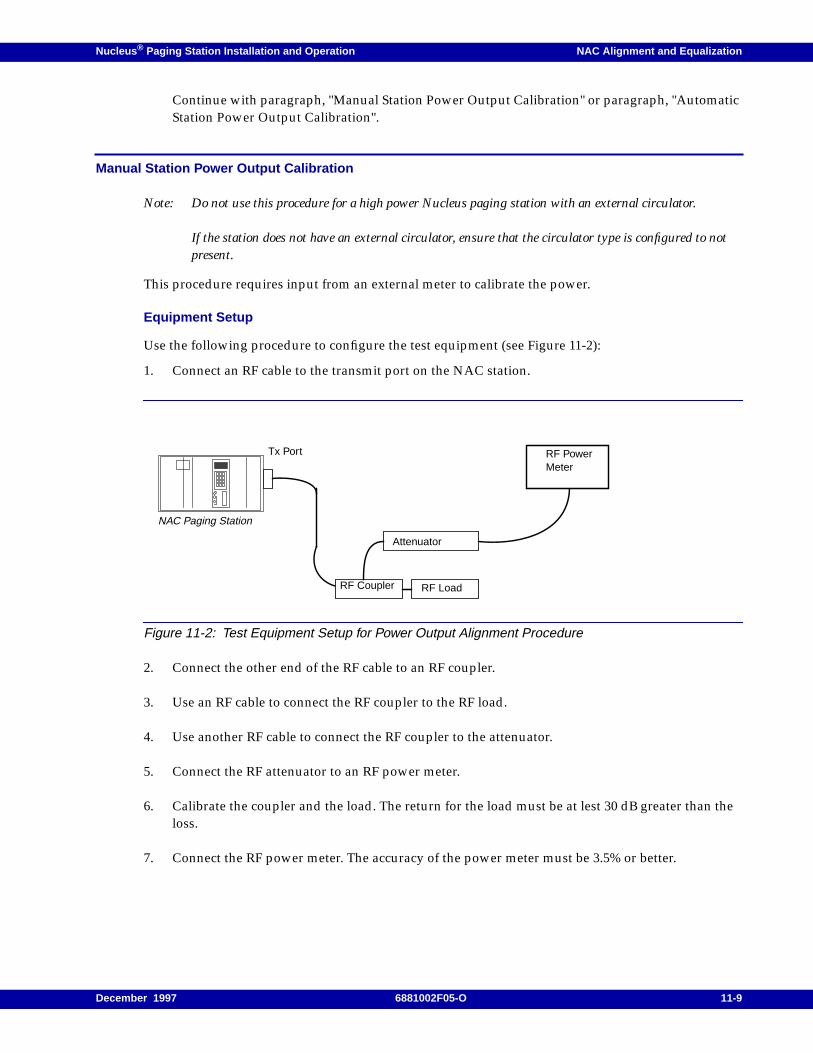
Nucleus ® Paging Station Installation and Operation NAC Alignment and Equalization
Continue with paragraph, "Manual Station Power Output Calibration" or paragraph, "AutomaticStation Power Output Calibration".
Manual Station Power Output Calibration
Note: Do not use this procedure for a high power Nucleus paging station with an external circulator.
If the station does not have an external circulator, ensure that the circulator type is configured to notpresent.
This procedure requires input from an external meter to calibrate the power.
Equipment Setup
Use the following procedure to configure the test equipment (see Figure 11-2):
1. Connect an RF cable to the transmit port on the NAC station.
Figure 11-2: Test Equipment Setup for Power Output Alignment Procedure
2. Connect the other end of the RF cable to an RF coupler.
3. Use an RF cable to connect the RF coupler to the RF load.
4. Use another RF cable to connect the RF coupler to the attenuator.
5. Connect the RF attenuator to an RF power meter.
6. Calibrate the coupler and the load. The return for the load must be at lest 30 dB greater than theloss.
7. Connect the RF power meter. The accuracy of the power meter must be 3.5% or better.
NAC Paging Station
Tx Port RF PowerMeter
RF Coupler RF Load
Attenuator
December 1997 6881002F05-O 11-9
NAC Alignment and Equalization Nucleus ® Paging Station Installation and Operation
Manual Calibration Procedure
This procedure requires the technician to read a power level from an external meter and to type it in atthe front panel. The station compares the measured power with the output power level, then raises orlowers the power level to achieve the correct value at the output.
Note: Complete the entire procedure. Terminating the calibration procedure before completion results in a lossof all data.
Use the following procedure to calibrate power:
1. From the READY prompt, press <ALGN> to access the Station Alignment menu.
The display briefly shows the ALGN menu, then shows the first submenu:
DE-EMP RX LEVEL
2. Press <down arrow> to access the CALIBRATE STATION POWER submenu.
3. Press <ENT>.
4. Press <down arrow> to access the CAL EXT WATTMETER option.
5. Press <ENT>.
The station keys and the Exciter PA Full LED lights.
The display shows the following message:
ENTER POWER MEASUREMENT
6. Read output power on the power meter.
7. Type the value from the power meter and press <ENT>.
Note: This alignment procedure prevents PA cutback by preventing large changes in output power. If theactual measured output power on the wattmeter is significantly less than the programmed power level,do not type the actual power level in the input measured power field. Type a value that is approximately20% less than the programmed value. Repeat this step until the actual measured power level is within20% of the programmed value. At this point, type the actual measured value.
For example, if the programmed value is 50 watts and the actual measured value is 15 watts, type thevalue 40 as the value repeatedly until the actual measured value is greater than 40 watts. Then beginentering the actual measured value (50) until the wattmeter indicates 50 watts.Repeat Step 5 throughStep 7 until the measured power equals of is very near the required operating power level.
8. Press <EXIT> three times to return to the READY prompt.
9. Detach the test equipment.
Continue with paragraph, "Reference Alignment".
11-10 6881002F05-O December 1997
Nucleus ® Paging Station Installation and Operation NAC Alignment and Equalization
Automatic Station Power Output Calibration
NAC software releases 3.100 and higher support automatic power output calibration on 900 Hzstations.
Use the following procedure to perform automatic power calibration:
1. Turn off the station.
2. Detach the PA power output alignment point from one of the following locations:
– Transmit antenna cable
– External circulator assembly
– Antenna relay module
3. Connect an RF load to the output of the PA cable.
4. Turn on the station and allow it to warm up for an hour.
5. From the READY prompt, press <ALGN> to access the Station Alignment menu.
The display briefly shows the ALGN menu, then shows the first submenu:
DE-EMP RX LEVEL
6. Press <down arrow> to access the CALIBRATE STATION POWER submenu.
7. Press <ENT>.
8. Press <down arrow> to access the AUTO PA CALIBRATION option.
9. Press <ENT>.
The display shows the following message:
PRESS ENTER TO START
10. Press <ENT>.
The station keys and automatically adjusts the output power until the power level is close to therequired operating power.
The station dekeys and the display shows the following message:
COMPLETE
11. If the display shows an ALIGNMENT FAILED! message before calibration is complete, check thefollowing items:
CAUTION
Do not use a label value from a PA from another station. Use the value from the PAinstalled in the station being calibrated.
December 1997 6881002F05-O 11-11
NAC Alignment and Equalization Nucleus ® Paging Station Installation and Operation
– The RF is disconnected from the station to the RF load.
– The PA failed to key.
– The PA cut back for one of the following reasons:- High VSWR- PA overdrive- Low PA supply voltage- High external circulator temperature- Antenna relay short- Battery revert
12. Press <EXIT> twice to return to the READY prompt.
Note: Do not press <EXIT> before the test is complete.
13. Disconnect the test equipment.
14. Reattach the PA power output alignment point to one of the following:
– Transmit antenna cable
– External circulator assembly
– Antenna relay module (depending upon which options your Nucleus station has).
Continue with paragraph, "External Wattmeter Calibration".
External Wattmeter Calibration
Note: Validate the current channel frequency before performing this procedure.
This procedure is used for stations with double circulators and triple circulators and externalWattmeters.
Motorola installs the external Wattmeter during manufacturing. It does not require recalibration undernormal circumstances. Perform this procedure if the Wattmeter is replaced.
1. From the READY prompt, press <CNFG> to access the Station Configuration menu.
The display briefly shows the CNFG menu, then shows the first submenu:
OPERATING PWR
2. Press <down arrow> to access the WATTMETER SETUP submenu.
3. Press <ENT>.
The display shows the first option:
WATTMETER POLL RESP
4. If the Wattmeter poll response is already programmed for external, go to Step 7. If the Wattmeterpoll responses is programmed to internal, press <ENT>.
The display flashes to show the NAC has entered the edit mode.
11-12 6881002F05-O December 1997
Nucleus ® Paging Station Installation and Operation NAC Alignment and Equalization
5. Press <TOG> to select EXTERNAL .
6. Press <ENT>.
The display stops flashing to show the NAC has stored the value.
7. Press <down arrow> to access the EXTERNAL WATTMETER TYPE.
8. Press <ENT>.
The display flashes to show the NAC has entered the edit mode.
9. Press <TOG> to select CLASS 1 .
10. Press <ENT>.
The display stops flashing to show the NAC has stored the value.
11. Press <EXIT> twice to return to the READY prompt.
12. From the READY prompt, press <ALGN> to access the Station Alignment menu.
The display briefly shows the ALGN menu, then shows the first submenu:
DE-EMP RX LEVEL
13. Press <down arrow> to access the CALIBRATE STN POWER submenu.
14. Press <ENT>.
The display shows the following message:
INITIALIZE POWER CALIBRATE
15. Press <down arrow> to access CAL EXT WATTMETER.
16. Press <ENT>.
The display shows the following message:
ENTER POWER MEASUREMENT
17. Press <ENT>.
18. Measure the output power using an accurate Wattmeter at the output of the antenna feed.
19. Type the output power on the keyboard and press <ENT>.
The NAC stores the power level.
20. Press <EXIT> twice to return to the READY prompt.
21. From the READY prompt, press <SERV> to access the Service Mode menu.
The display briefly shows the SERV menu, then shows the first submenu.
KEY AND READ EXT POWER
December 1997 6881002F05-O 11-13
NAC Alignment and Equalization Nucleus ® Paging Station Installation and Operation
22. Press <ENT>.
The display shows the Wattmeter reading.
23. Verify that the Wattmeter reading matches the external measurement.
24. If the two values do not match, repeat Step 12 through Step 23 until the Wattmeter readingmatches the external measurement.
25. Press <EXIT> twice to return to the READY prompt.
Continue with paragraph, "Reference Alignment".
Reference Alignment
This procedure aligns the frequency reference. This procedure adjusts the carrier frequency to within1 Hz of the programmed frequency value. Use this procedure if system specifications require betterperformance that provided by system specifications, or if the system nets the oscillators.
Note: Validate the current channel frequency before performing this procedure.
Set TX>FREQ ADJUST to zero (0).
This procedure requires a frequency counter or communication analyzer to align the Pendulum valueand the reference module. the accuracy of the test equipment should be 10 times better than theoscillator it needs to measure (3ppb for an HSO and 0.5 ppb for a UHSO).
Do not perform this procedure if the station uses an external frequency reference or has no reference.
Use the following procedure to align the reference (see Figure 11-3):
1. Connect the N-type connector from the PA output alignment point to the RF coupler.
2. Connect the RF coupler to an RF load
3. Connect the RF coupler to an attenuator.
4. Connect the attenuator to the front panel of a Motorola R2000 Series Communications Analyzer.
5. Connect a rubidium standard to the ref port of the Motorola R2000 Series CommunicationsAnalyzer.
11-14 6881002F05-O December 1997
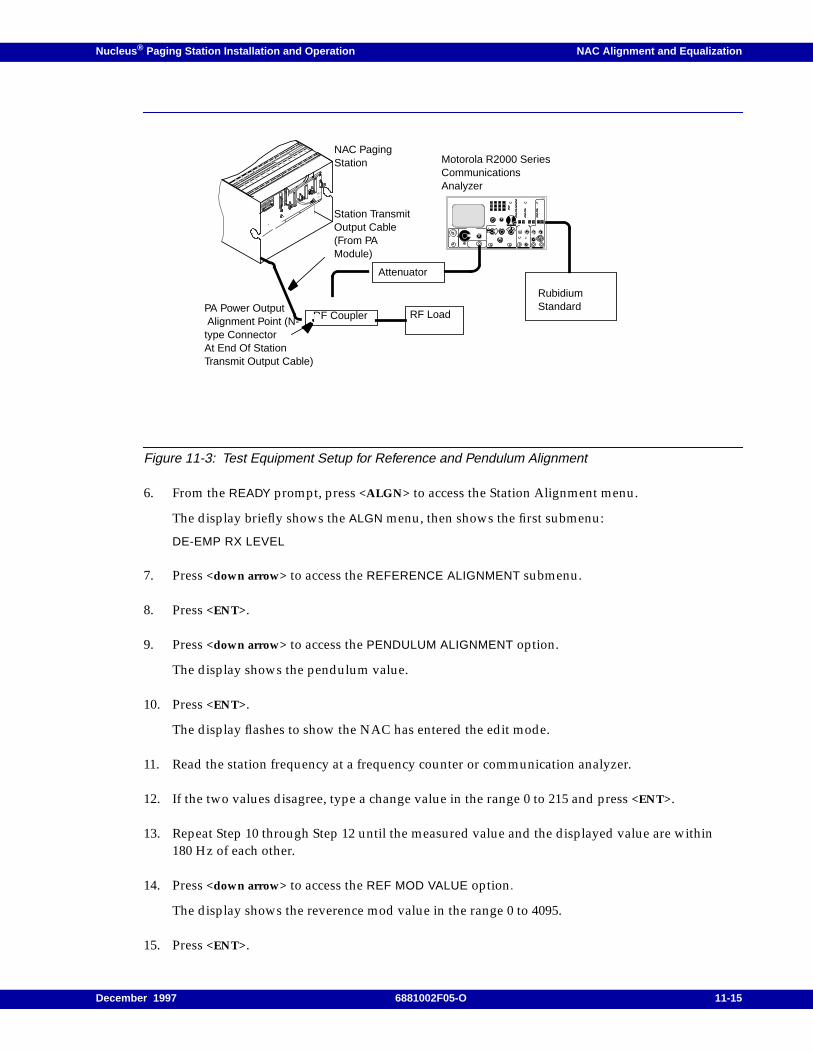
Nucleus ® Paging Station Installation and Operation NAC Alignment and Equalization
Figure 11-3: Test Equipment Setup for Reference and Pendulum Alignment
6. From the READY prompt, press <ALGN> to access the Station Alignment menu.
The display briefly shows the ALGN menu, then shows the first submenu:
DE-EMP RX LEVEL
7. Press <down arrow> to access the REFERENCE ALIGNMENT submenu.
8. Press <ENT>.
9. Press <down arrow> to access the PENDULUM ALIGNMENT option.
The display shows the pendulum value.
10. Press <ENT>.
The display flashes to show the NAC has entered the edit mode.
11. Read the station frequency at a frequency counter or communication analyzer.
12. If the two values disagree, type a change value in the range 0 to 215 and press <ENT>.
13. Repeat Step 10 through Step 12 until the measured value and the displayed value are within180 Hz of each other.
14. Press <down arrow> to access the REF MOD VALUE option.
The display shows the reverence mod value in the range 0 to 4095.
15. Press <ENT>.
NAC PagingStation
RF Coupler
Attenuator
RF Load
Motorola R2000 SeriesCommunicationsAnalyzer
Station TransmitOutput Cable(From PAModule)
PA Power Output Alignment Point (N-type ConnectorAt End Of StationTransmit Output Cable)
RubidiumStandard
December 1997 6881002F05-O 11-15
NAC Alignment and Equalization Nucleus ® Paging Station Installation and Operation
The display flashes to show the NAC has entered the edit mode.
16. If the display value does not match the station frequency shown on the frequency counter orcommunication analyzer, type a value in the range 0 to 4095 to begin correcting the value.
17. Press <ENT>.
18. Repeat Step 15 through Step 17 until the display value is within 1 Hz of the measured value.
19. Press <EXIT> twice to return to the READY prompt.
20. Continue with paragraph, "VCO Modulation Sensitivity Calibration".
VCO Modulation Sensitivity Calibration
This calibration procedure accounts for modulation sensitivity variations in the Voltage controlledoscillator (VCO). Motorola calibrates the VCO during manufacturing.
Note: Align the frequencies according to the following specifications:- Align Frequency 1 as the lowest frequency in the band ±25 kHz.- Align Frequency 2 at 25 kHz less that the frequency in the middle of the band.- Align Frequency 3 at 25 kHz greater than the frequency in the middle of the band.- Align Frequency 4 at the highest frequency in the band ±25 kHz.
Use the following procedure after replacement of a NAC board or Exciter.
1. Connect the test equipment as shown in Figure 11-3.
2. From the READY prompt, press <ALGN> to access the Station Alignment menu.
The display briefly shows the ALGN menu, then shows the first submenu:
DE-EMP RX LEVEL
3. Press <down arrow> to access the VCO MODULATION FREQS submenu.
4. Press <ENT>.
The display shows the first frequency deviation:
FREQ 1 DEV: XXXX
5. Press <ENT>.
The station keys and modulates the transmitter with a software-generated 1012.5 Hz tone. Thedisplay shows the current correction table entry.
6. Type the deviation shown on an external frequency deviation meter and press <ENT>.
7. Press <down arrow> to access the next value.
8. Perform Step 5 through Step 7 to calibrate the four frequency deviations.
11-16 6881002F05-O December 1997
Nucleus ® Paging Station Installation and Operation NAC Alignment and Equalization
9. Press <EXIT> twice to return to the READY prompt.
Continue with paragraph, "Analog Deviation Verification".
Analog Deviation Verification
Motorola aligns each NAC station for nominal audio transmit deviation of ±3 kHz, and maximumaudio deviation of ±5 kHz. Use the following procedure to verify or change these values:
Note: Validate the current channel frequency before performing this procedure.
1. From the READY prompt, press <TX> to access the Transmit menu.
The display briefly shows the TX menu, then shows the first submenu:
FREQ ADJUST
2. Press <down arrow> to access the TX DEVIATION SETUP submenu.
The display shows the following message:
MAXIMUM DEVIATION: XXXX
The value is in the range 0 to 7000 Hz (in 1 Hz increments).
3. Press <ENT>.
The display flashes to show the NAC has entered the edit mode.
4. Type a new value and press <ENT>.
The display stops flashing to show the NAC has stored the value.
5. Apply a 2 kHz test tone at the system level to Line 1.
6. If the station is equipped with a link receiver option, modulate an on-channel RF signal with a1 kHz test tone at system deviation.
7. Press <EXIT> twice to return to the READY prompt.
8. From the READY prompt, press <ALGN> to access the Station Alignment menu.
The display briefly shows the ALGN menu, then shows the first submenu:
DE-EMP RX LEVEL
9. Press <down arrow> to access the NOMINAL DEVIATION submenu.
10. Press <ENT>.
The station keys and modulates the carrier with the test tone at the nominal deviation level.
The display shows the nominal deviation.
11. Monitor the nominal deviation.
December 1997 6881002F05-O 11-17
NAC Alignment and Equalization Nucleus ® Paging Station Installation and Operation
12. To change the nominal deviation type the new deviation and press <ENT>.
13. Repeat Step 10 through Step 12 to ensure the new deviation is correct.
14. Press <EXIT> twice to return to the READY prompt.
15. Continue with paragraph, "Transmit Audio Response".
Transmit Audio Response
Use the following procedure to ensure that the transmit audio response is flat:
1. From the READY prompt, press <TX> to access the Transmit menu.
The display briefly shows the TX menu, then shows the first submenu:
FREQ ADJUST
2. Press <down arrow> to access the FLAT/PRE-EMPHASIS submenu.
The display shows the current setting:
FLAT
or
PRE-EMP
Note: Pre-emphasis response is 6 dB per octave.
3. If the current value is flat, go to Step 6. If the current value is pre-emphasis, press <ENT>.
The display flashes to show the NAC is in the edit mode.
4. Press <TOG> to select FLAT.
5. Press <ENT>.
The display stops flashing to show the NAC has stored the data.
6. Press <EXIT> twice to return to the READY prompt.
Continue with paragraph, "Binary Splatter Filter".
Binary Splatter Filter
The binary splatter filter configures the station for compatibility with other paging transmitters in thesystem. The default value is a rise time of 140 ms or can be changed to read 250 ms. Use the followingprocedure to select the splatter filter:
1. From the READY prompt, press <TX> to access the Transmit menu.
The display briefly shows the TX menu, then shows the first submenu:
FREQ ADJUST
11-18 6881002F05-O December 1997
Nucleus ® Paging Station Installation and Operation NAC Alignment and Equalization
2. Press <down arrow> to access the BINARY SPLATTER FILTER submenu.
The display shows the current value.
3. If the default rise time (140 ms) is correct, go to Step 6. If the default rise time is incorrect, press<ENT>.
The display flashes to show the NAC is in the edit mode.
4. Press <TOG> to select 250 ms.
5. Press <ENT>.
The display stops flashing to show the NAC has stored the data.
6. Press <EXIT> twice to return to the READY prompt.
Continue with the appropriate procedure:
– SRM alignment if the NAC board or Exciter has been replaced (see paragraph, "SRMAlignment")
– Line 2 output level adjustment (see paragraph, "Line 2 Output Level Adjust")
– Line 2 adjustment for an external monitor receiver (see paragraph, "Line 2 Adjustment for anExternal Monitor Receiver Audio Source")
– Line 2 adjustment for an internal tone-encoding source (see paragraph, "Line 2 Adjustment foran Internal Tone-Encoded Source")
– Binary deviation programming (see paragraph, "Binary Deviation Values")
– Internal receiver test tone (see paragraph, "Internal RX Test Tone")
– Alignment completion (see paragraph, "Alignment Completion")
SRM Alignment
Note: Perform SRM alignment only if the NAC board or Exciter is replaced.
This procedure fine-tunes the deviation of the square-wave transmit data.
This procedure requires a modulation domain analyzer.
1. Connect the modulation domain analyzer to the station.
2. From the READY prompt, press <ALGN> to access the Station Alignment menu.
The display briefly shows the ALGN menu, then shows the first submenu:
DE-EMP RX LEVEL
3. Press <down arrow> to access the SRM ALIGNMENT submenu.
4. Press <ENT>.
5. Press <down arrow> to access the DELAY option. The display shows the current delay value in therange 0.00 to 19.75.
December 1997 6881002F05-O 11-19
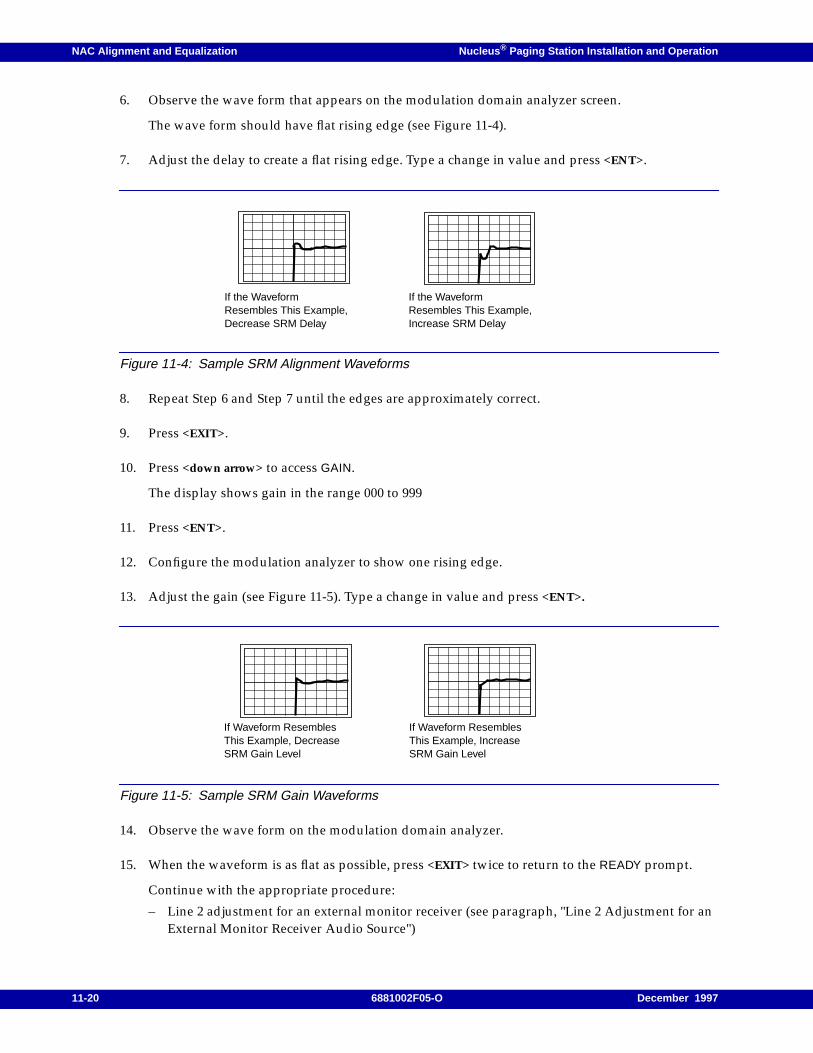
NAC Alignment and Equalization Nucleus ® Paging Station Installation and Operation
6. Observe the wave form that appears on the modulation domain analyzer screen.
The wave form should have flat rising edge (see Figure 11-4).
7. Adjust the delay to create a flat rising edge. Type a change in value and press <ENT>.
Figure 11-4: Sample SRM Alignment Waveforms
8. Repeat Step 6 and Step 7 until the edges are approximately correct.
9. Press <EXIT>.
10. Press <down arrow> to access GAIN.
The display shows gain in the range 000 to 999
11. Press <ENT>.
12. Configure the modulation analyzer to show one rising edge.
13. Adjust the gain (see Figure 11-5). Type a change in value and press <ENT>.
Figure 11-5: Sample SRM Gain Waveforms
14. Observe the wave form on the modulation domain analyzer.
15. When the waveform is as flat as possible, press <EXIT> twice to return to the READY prompt.
Continue with the appropriate procedure:
– Line 2 adjustment for an external monitor receiver (see paragraph, "Line 2 Adjustment for anExternal Monitor Receiver Audio Source")
If the WaveformResembles This Example,Decrease SRM Delay
If the WaveformResembles This Example,Increase SRM Delay
If Waveform ResemblesThis Example, DecreaseSRM Gain Level
If Waveform ResemblesThis Example, IncreaseSRM Gain Level
11-20 6881002F05-O December 1997
Nucleus ® Paging Station Installation and Operation NAC Alignment and Equalization
– Line 2 adjustment for an internal tone-encoding source (see paragraph, "Line 2 Adjustment foran Internal Tone-Encoded Source")
– Binary deviation programming (see paragraph, "Binary Deviation Values")
– Internal receiver test tone (see paragraph, "Internal RX Test Tone")
– Alignment completion (see paragraph, "Alignment Completion")
Line 2 Output Level Adjust
This section describes adjustments for wireline MDC tones, verification tones, or monitor receiveraudio. The source of the Line 2 output audio is internal or external. The internal source is a set of tonesgenerated by the NAC board. An external source is a set of tones generated on a monitor receiver androute to the NAC board. This section describes procedures for both sources.
Line 2 Adjustment for an External Monitor Receiver Audio Source
Note: This procedure requires an RF signal generator connected to the receiver antenna connection.
Use this procedure for a station with option C664 monitor receiver or the equivalent field upgrade:
1. Turn off the monitor receiver.
2. Remove the Audio and Squelch board.
3. Mount the Audio and Squelch board on an extender card.
4. Install the extender card in the monitor receiver.
5. Turn on the monitor receiver.
6. From the READY prompt on the NAC front panel, press <ALGN> to access the Station Alignmentmenu.
The display briefly shows the ALGN menu, then shows the first submenu:
DE-EMP RX LEVEL
7. Press <ENT>.
8. Connect an RF signal generator to the receiver antenna connection.
9. Adjust the generator output for an RF level of 1000 mV rms, modulated with a 1000 Hz test toneat system deviation.
10. Adjust R203 on the monitor receiver Audio and Squelch board until the display shows a reading0.40 ±0.05 V. This reading corresponds to a receiver output of -5 dBm.
From the NAC control panel press <EXIT> once to return to the ALGN menu and the DE-EMP RXLEVEL submenu.
11. Press <down arrow> to access the OUTPUT RX AUDIO submenu.
December 1997 6881002F05-O 11-21
NAC Alignment and Equalization Nucleus ® Paging Station Installation and Operation
12. The display shows the wiper position of the Line 2 level adjustment potentiometer.
The gain range, from lowest to highest, is 0 to 255.
13. To adjust the wiper position, press <ENT>.
The display flashes to show the NAC has entered the edit mode.
14. Type the new value for the Line 2 level and press <ENT>.
The display stops flashing to show the NAC has stored the value.
15. Press <EXIT> twice to return to the READY prompt.
Continue with the appropriate procedure:
– Line 2 adjustment for an internal tone-encoding source (see paragraph, "Line 2 Adjustment foran Internal Tone-Encoded Source")
– Binary deviation programming (see paragraph, "Binary Deviation Values")
– Internal receiver test tone (see paragraph, "Internal RX Test Tone")
– Alignment completion (see paragraph, "Alignment Completion")
Line 2 Adjustment for an Internal Tone-Encoded Source
Use this procedure for MDC or verification tone generation.
1. From the READY prompt, press <ALGN> to access the Station Alignment menu.
The display briefly shows the ALGN menu, then shows the first submenu:
DE-EMP RX LEVEL
2. Press <down arrow> to access the OUTPUT AUDIO INTERNAL SOURCE submenu.
3. Press <ENT>.
The display shows the wiper position of the Line 2 level adjustment potentiometer.
The gain range, from lowest to highest, is 0 to 255.
4. To adjust the wiper position, press <ENT>.
The display flashes to show the NAC has entered the edit mode.
5. Type the new value for the Line 2 level and press <ENT>.
The display stops flashing to show the NAC has stored the value.
6. Press <EXIT> twice to return to the READY prompt.
Continue with the appropriate procedure:
– Binary deviation programming (see paragraph, "Binary Deviation Values")
– Internal receiver test tone (see paragraph, "Internal RX Test Tone")
– Alignment completion (see paragraph, "Alignment Completion")
11-22 6881002F05-O December 1997
Nucleus ® Paging Station Installation and Operation NAC Alignment and Equalization
Binary Deviation Values
Motorola configures the NAC board for a binary transmit deviation of ±4 kHz during manufacturing.Use the following procedure to display the current value without keying the station:
1. From the READY prompt, press <TX> to access the Transmit menu.
The display briefly shows the ALGN menu, then shows the first submenu:
FREQ ADJUST
2. Press <down arrow> to access the TX DEVIATION SETUP submenu.
3. Press <ENT>.
The display shows the MAXIMUM DEVIATION option.
4. Press <down arrow> to access the NOMINAL DEVIATION SETUP value.
NOMINAL DEVIATION XXXX
This value is the wiper position of the Line 2 level adjustment potentiometer.
5. Press <EXIT> twice to return to the READY prompt.
6. From the READY prompt, press <ALGN> to access the Station Alignment menu.
The display briefly shows the ALGN menu, then shows the first submenu:
DE-EMP RX LEVEL
7. Press <down arrow> to access the BINARY INST submenu.
8. The NAC shows the current binary deviation value in Hz.
9. Press <EXIT> twice to return to the READY prompt.
Continue with the appropriate procedure:
– Internal receiver test tone (see paragraph, "Internal RX Test Tone")
– Alignment completion (see paragraph, "Alignment Completion")
Internal RX Test Tone
Use the internal receiver test tone for the following functions:
• Setting status tone level
• Measuring phone line response
Use the following procedure to set the internal receiver test tone:
1. From the READY prompt, press <ALGN> to access the Station Alignment menu.
The display briefly shows the ALGN menu, then shows the first submenu:
DE-EMP RX LEVEL
December 1997 6881002F05-O 11-23
NAC Alignment and Equalization Nucleus ® Paging Station Installation and Operation
2. Press <down arrow> to access the Internal RX TEST TONE SETUP submenu.
3. Press <ENT>.
The display shows the test tone value.
The display flashes to show the NAC has entered the edit mode.
4. Press <TOG> to select ENABLED .
5. Press <ENT>.
The display stops flashing to show the NAC has stored the value.
6. Press <down arrow> to access TEST TONE FREQ.
7. Press <ENT>.
The display shows the test tone frequency.
The display flashes to show the NAC has entered the edit mode.
8. Type a value in the range 300 to 3000 Hz.
9. Press <ENT>.
The display stops flashing to show the NAC has stored the value.
10. Press <EXIT> twice to return to the READY prompt.
Continue with paragraph, "Alignment Completion".
Alignment Completion
The station is now fully aligned.
If the NAC station is part of a simulcast group, continue with paragraph, "Simulcast Equalization".
11-24 6881002F05-O December 1997
Nucleus ® Paging Station Installation and Operation NAC Alignment and Equalization
Simulcast Equalization
This section defines simulcast equalization for simulcast operation. The rest of the section gives thespecific procedures for configuring a station for simulcast equalization.
Simulcast Operation
A simulcast system covers a continuous geographic area with more than one station transmitter. In asimulcast system, every station sends a message at the same time. However, each transmitter mayreceive the message at a slightly different time because of delays in the system that vary from stationto station. Every distribution path, wireline, radio link, or satellite, has a different signal arrival time toeach transmitter.
Equalization introduces delays to stations nearest the source. These delays cause the stations to wait aprogrammed length of time before paging to ensure that they are simulcast with stations farther fromthe source. val to each transmitter from the paging terminal. The NAC has a 0 to 262.143 ms variabledelay (Digital Delay Line) that is controlled from the front panel or from the Advanced SimulcastController (ASC).
Automatic Delay
Automatic Delay Equalization is an equalization system for the outbound station control path. Theconsists of the ASC 1500 controller, a NAC stations, and at least one Spectra-TAC monitor receiversystem. The ASC 1500 measure station closed loop audio propagation delays individually andcompares all the stations in the system. The ASC uses these readings to adjust the system for simulcasttransmission.
Delay measurements use an analog closed loop path from the ASC 1500 to the station and back (seeFigure 11-6). The analog closed loop path consists of the following items:
• Outbound control path from the ASC to the station (wireline or RF link)
• Station analog transmit audio path with digital delay line
• RF transmission from the station to a Spectra-TAC monitor receiver
• Return dedicated phone line from the Spectra-TAC monitor receiver to a Spectra-TAC votingcomparator
• Audio link to the ASC.
December 1997 6881002F05-O 11-25
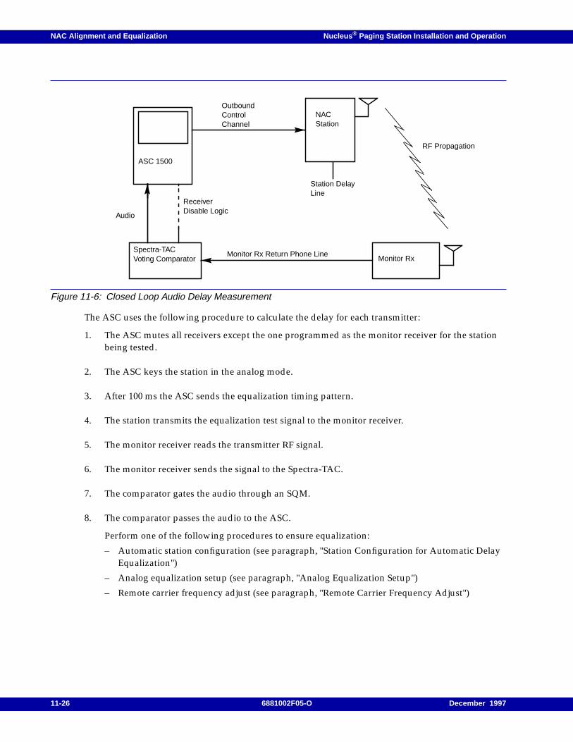
NAC Alignment and Equalization Nucleus ® Paging Station Installation and Operation
Figure 11-6: Closed Loop Audio Delay Measurement
The ASC uses the following procedure to calculate the delay for each transmitter:
1. The ASC mutes all receivers except the one programmed as the monitor receiver for the stationbeing tested.
2. The ASC keys the station in the analog mode.
3. After 100 ms the ASC sends the equalization timing pattern.
4. The station transmits the equalization test signal to the monitor receiver.
5. The monitor receiver reads the transmitter RF signal.
6. The monitor receiver sends the signal to the Spectra-TAC.
7. The comparator gates the audio through an SQM.
8. The comparator passes the audio to the ASC.
Perform one of the following procedures to ensure equalization:
– Automatic station configuration (see paragraph, "Station Configuration for Automatic DelayEqualization")
– Analog equalization setup (see paragraph, "Analog Equalization Setup")
– Remote carrier frequency adjust (see paragraph, "Remote Carrier Frequency Adjust")
ASC 1500
Audio
OutboundControlChannel
NACStation
Monitor RxSpectra-TACVoting Comparator
Monitor Rx Return Phone Line
ReceiverDisable Logic
Station DelayLine
RF Propagation
11-26 6881002F05-O December 1997
Nucleus ® Paging Station Installation and Operation NAC Alignment and Equalization
Station Configuration for Automatic Delay Equalization
Use the following procedure to configure the station for automatic delay equalization:
1. From the READY prompt, press <RX> to access the Receive Audio menu.
The display briefly shows the RX menu, then shows the first submenu:
INPUT AUDIO FROM
2. Press <down arrow> to access the DELAY submenu.
The display shows the current value.
DELAY ENABLE
or
DELAY DISABLE
3. Press <ENT>.
The display flashes to show the NAC has entered the edit mode.
4. If delay is already enabled, go to Step 6. If delay is disabled, press <TOG> to select ENABLED .
5. Press <ENT>.
The display stops flashing to show the NAC has stored the value.
6. Press <EXIT> twice to return to the READY prompt.
7. From the READY prompt, press <OPT1> to access the Station Options menu.
The display briefly shows the OPT1 menu, then shows the first submenu:
SPECIAL KEY DISABLED
8. Press <down arrow> to access the EXTERNAL PAGING DATA SETUP submenu.
9. Press <ENT>.
10. Press <down arrow> to access DELAY PATH.
The display shows the current value.
11. Press <ENT>.
The display flashes to show the NAC has entered the edit mode.
12. Press <TOG> to select DIGITAL .
13. Press <ENT>.
The display stops flashing to show the NAC has stored the value.
14. Press <EXIT> twice to return to the READY prompt.
December 1997 6881002F05-O 11-27
NAC Alignment and Equalization Nucleus ® Paging Station Installation and Operation
15. From the READY prompt, press <TX> to access the Transmit menu.
The display briefly shows the TX menu, then shows the first submenu:
FREQ ADJUST
16. Press <down arrow> to access the GT NOTCH submenu.
The display shows the current value.
17. Press <ENT>.
The display flashes to show the NAC has entered the edit mode.
18. Press <TOG> to select DISABLED .
19. Press <ENT>.
The display stops flashing to show the NAC has stored the value.
20. Press <EXIT> twice to return to the READY prompt.
21. Calibrate the VCO sensitivity (see paragraph, "VCO Modulation Sensitivity Calibration").
22. From the READY prompt, press <TX> to access the Transmit menu.
The display briefly shows the TX menu, then shows the first submenu:
FREQ ADJUST
23. Press <down arrow> to access the AUDIO DEVIATION submenu.
The display shows the current value.
24. Press <ENT>.
The display flashes to show the NAC has entered the edit mode.
25. Type a value in the range 3.0 to 4,0 kHz and press <ENT>.
The display stops flashing to show the NAC has stored the value.
26. Configure the transmit audio response to be flat (see paragraph, "Transmit Audio Response").
27. Press <EXIT> twice to return to the READY prompt.
Analog Equalization Setup
In analog simulcast systems, especially those with voice paging, the audio response for all stationsmust match. When a NAC station is installed in a system with other types of transmitters, the NACstation requires adjustment for the audio response.
11-28 6881002F05-O December 1997
Nucleus ® Paging Station Installation and Operation NAC Alignment and Equalization
Use the following procedure to configure analog equalization:
1. From the READY prompt, press <TX> to access the Transmit menu.
The display briefly shows the TX menu, then shows the first submenu:
FREQ ADJUST
2. Press <down arrow> to access the ANLG EQ FILTER submenu.
The display shows the current value.
3. Press <ENT>.
The display flashes to show the NAC has entered the edit mode.
4. Press <TOG> to select one of the following:
– ENABLED for networks where some transmitters do not have advanced control
– DISABLED for networks that do have advanced control
5. Press <ENT>.
The display stops flashing to show the NAC has stored the value.
6. Press <EXIT> once.
7. Press <down arrow> to access the SPECIAL TX SETUP submenu.
The display shows the current value.
8. Press <ENT>.
The display shows Audio Phase Invert option.
9. Press <ENT>.
The display flashes to show the NAC has entered the edit mode.
10. Press <TOG> to select the correct audio phase inversion (see Table 11-1).
December 1997 6881002F05-O 11-29

NAC Alignment and Equalization Nucleus ® Paging Station Installation and Operation
11. Press <ENT>.
The display stops flashing to show the NAC has stored the value.
12. Press <EXIT> twice to return to the READY prompt.
13. From the READY prompt, press <RX> to access the Receive Audio menu.
The display briefly shows the RX menu, then shows the first submenu:
INPUT AUDIO FROM...
14. Press <down arrow> to access the Delay (value) submenu.
15. Press <ENT>.
The display flashes to show the NAC has entered the edit mode.
16. Type a value in the range 0 to 262.143 ms. Do not type the decimal point; it is in a fixed position.
17. Press <ENT>.
The display stops flashing to show the NAC has stored the value.
Remote Carrier Frequency Adjust
The carrier frequency adjust feature remote control of the station transmit carrier frequency from theASC. The NAC board fine tunes an ultra high stability oscillators (UHSO) or high stability oscillator(HSO) steering line to increase or decrease the transmit frequency. Fine tuning consists of 99 steps: 49steps for decrementing the value and 50 steps for incrementing the value, centered around 0 (seeTable 11-2).
Note: Motorola sets the remote frequency adjustment potentiometer to +0 steps. Centering around 0 providesmaximum swing up and down for fine tuning the carrier frequency.
Table 11-1: Mixed Analog Simulcast Setup
FirstStation
Second Stationand Control Type
Control Delay 1 Delay 2InvertAudioPhase
NAC
Micor ACBWireline 150 µs 0 µs Yes
Link 118 µs 0 µs Yes
Micor TRCWireline 0 µs 2590 µs Yes
Link 0 µs 2560 µs Yes
PURC 5000 TRCWireline 0 µs 2560 µs Yes
Link 0 µs 2560 µs Yes
PURC 5000 ACBWireline 0 µs 0 µs No
Link 0 µs 0 µs No
11-30 6881002F05-O December 1997
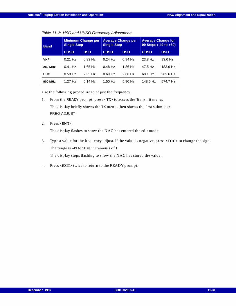
Nucleus ® Paging Station Installation and Operation NAC Alignment and Equalization
Use the following procedure to adjust the frequency:
1. From the READY prompt, press <TX> to access the Transmit menu.
The display briefly shows the TX menu, then shows the first submenu:
FREQ ADJUST
2. Press <ENT>.
The display flashes to show the NAC has entered the edit mode.
3. Type a value for the frequency adjust. If the value is negative, press <TOG> to change the sign.
The range is -49 to 50 in increments of 1.
The display stops flashing to show the NAC has stored the value.
4. Press <EXIT> twice to return to the READY prompt.
Table 11-2: HSO and UHSO Frequency Adjustments
Band
Minimum Change perSingle Step
Average Change perSingle Step
Average Change for99 Steps (-49 to +50)
UHSO HSO UHSO HSO UHSO HSO
VHF 0.21 Hz 0.83 Hz 0.24 Hz 0.94 Hz 23.8 Hz 93.0 Hz
280 MHz 0.41 Hz 1.65 Hz 0.48 Hz 1.86 Hz 47.5 Hz 183.9 Hz
UHF 0.58 Hz 2.35 Hz 0.69 Hz 2.66 Hz 68.1 Hz 263.6 Hz
900 MHz 1.27 Hz 5.14 Hz 1.50 Hz 5.80 Hz 148.6 Hz 574.7 Hz
December 1997 6881002F05-O 11-31

NAC Alignment and Equalization Nucleus ® Paging Station Installation and Operation
11-32 6881002F05-O December 1997
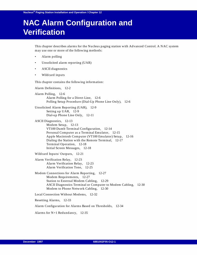
Nucleus ® Paging Station Installation and Operation / Chapter 12
NAC Alarm Configuration andVerification 12
This chapter describes alarms for the Nucleus paging station with Advanced Control. A NAC systemmay use one or more of the following methods:
• Alarm polling
• Unsolicited alarm reporting (UAR)
• ASCII diagnostics
• Wildcard inputs
This chapter contains the following information:
Alarm Definitions, 12-2
Alarm Polling, 12-6Alarm Polling for a Direct Line, 12-6Polling Setup Procedure (Dial-Up Phone Line Only), 12-6
Unsolicited Alarm Reporting (UAR), 12-9Setting up UAR, 12-9Dial-up Phone Line Only, 12-11
ASCII Diagnostics, 12-13Modem Setup, 12-13VT100 Dumb Terminal Configuration, 12-14Personal Computer as a Terminal Emulator, 12-15Apple Macintosh Computer (VT100 Emulator) Setup, 12-16Dialing the Station with the Remote Terminal, 12-17Terminal Operation, 12-18Initial Screen Messages, 12-18
Wildcard Inputs/Outputs, 12-21
Alarm Verification Relay, 12-23Alarm Verification Relay, 12-23Alarm Verification Tone, 12-25
Modem Connections for Alarm Reporting, 12-27Modem Requirements, 12-27Station to External Modem Cabling, 12-29ASCII Diagnostics Terminal or Computer to Modem Cabling, 12-30Modem to Phone Network Cabling, 12-30
Local Connection Without Modems, 12-32
Resetting Alarms, 12-33
Alarm Configuration for Alarms Based on Thresholds, 12-34
Alarms for N+1 Redundancy, 12-35
December 1997 6881002F05-O12-1
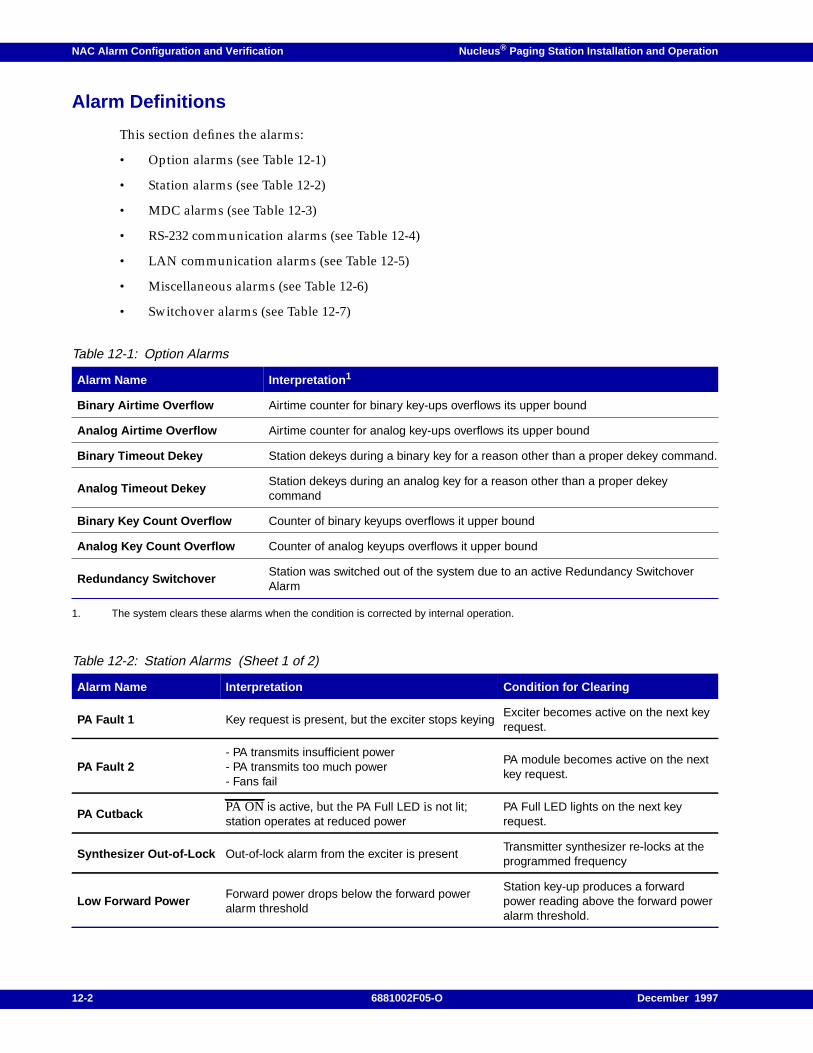
NAC Alarm Configuration and Verification Nucleus ® Paging Station Installation and Operation
Alarm Definitions
This section defines the alarms:
• Option alarms (see Table 12-1)
• Station alarms (see Table 12-2)
• MDC alarms (see Table 12-3)
• RS-232 communication alarms (see Table 12-4)
• LAN communication alarms (see Table 12-5)
• Miscellaneous alarms (see Table 12-6)
• Switchover alarms (see Table 12-7)
1. The system clears these alarms when the condition is corrected by internal operation.
Table 12-1: Option Alarms
Alarm Name Interpretation 1
Binary Airtime Overflow Airtime counter for binary key-ups overflows its upper bound
Analog Airtime Overflow Airtime counter for analog key-ups overflows its upper bound
Binary Timeout Dekey Station dekeys during a binary key for a reason other than a proper dekey command.
Analog Timeout DekeyStation dekeys during an analog key for a reason other than a proper dekeycommand
Binary Key Count Overflow Counter of binary keyups overflows it upper bound
Analog Key Count Overflow Counter of analog keyups overflows it upper bound
Redundancy SwitchoverStation was switched out of the system due to an active Redundancy SwitchoverAlarm
Table 12-2: Station Alarms (Sheet 1 of 2)
Alarm Name Interpretation Condition for Clearing
PA Fault 1 Key request is present, but the exciter stops keyingExciter becomes active on the next keyrequest.
PA Fault 2- PA transmits insufficient power- PA transmits too much power- Fans fail
PA module becomes active on the nextkey request.
PA CutbackPA ON is active, but thePA Full LED is not lit;station operates at reduced power
PA Full LED lights on the next keyrequest.
Synthesizer Out-of-Lock Out-of-lock alarm from the exciter is presentTransmitter synthesizer re-locks at theprogrammed frequency
Low Forward PowerForward power drops below the forward poweralarm threshold
Station key-up produces a forwardpower reading above the forward poweralarm threshold.
12-2 6881002F05-O December 1997
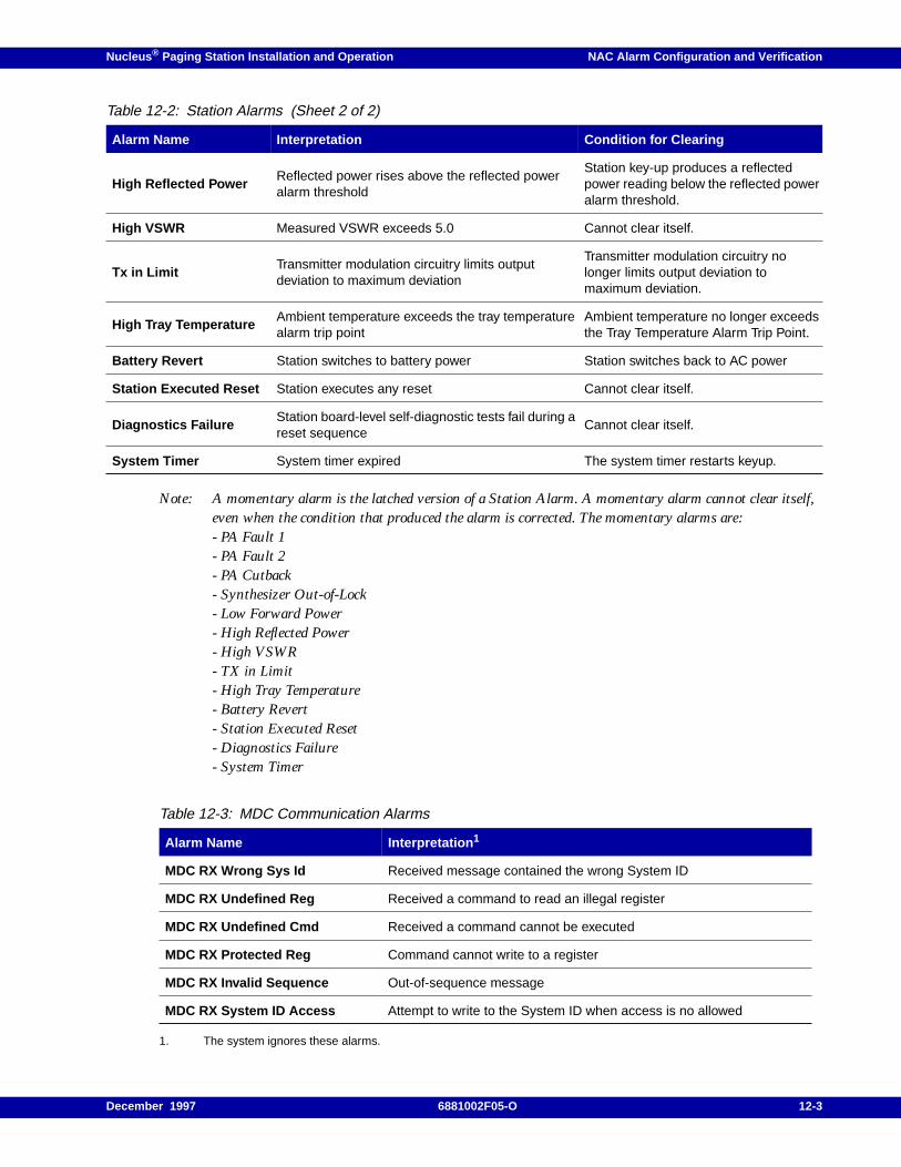
Nucleus ® Paging Station Installation and Operation NAC Alarm Configuration and Verification
Note: A momentary alarm is the latched version of a Station Alarm. A momentary alarm cannot clear itself,even when the condition that produced the alarm is corrected. The momentary alarms are:- PA Fault 1- PA Fault 2- PA Cutback- Synthesizer Out-of-Lock- Low Forward Power- High Reflected Power- High VSWR- TX in Limit- High Tray Temperature- Battery Revert- Station Executed Reset- Diagnostics Failure- System Timer
1. The system ignores these alarms.
High Reflected PowerReflected power rises above the reflected poweralarm threshold
Station key-up produces a reflectedpower reading below the reflected poweralarm threshold.
High VSWR Measured VSWR exceeds 5.0 Cannot clear itself.
Tx in LimitTransmitter modulation circuitry limits outputdeviation to maximum deviation
Transmitter modulation circuitry nolonger limits output deviation tomaximum deviation.
High Tray TemperatureAmbient temperature exceeds the tray temperaturealarm trip point
Ambient temperature no longer exceedsthe Tray Temperature Alarm Trip Point.
Battery Revert Station switches to battery power Station switches back to AC power
Station Executed Reset Station executes any reset Cannot clear itself.
Diagnostics FailureStation board-level self-diagnostic tests fail during areset sequence
Cannot clear itself.
System Timer System timer expired The system timer restarts keyup.
Table 12-3: MDC Communication Alarms
Alarm Name Interpretation 1
MDC RX Wrong Sys Id Received message contained the wrong System ID
MDC RX Undefined Reg Received a command to read an illegal register
MDC RX Undefined Cmd Received a command cannot be executed
MDC RX Protected Reg Command cannot write to a register
MDC RX Invalid Sequence Out-of-sequence message
MDC RX System ID Access Attempt to write to the System ID when access is no allowed
Table 12-2: Station Alarms (Sheet 2 of 2)
Alarm Name Interpretation Condition for Clearing
December 1997 6881002F05-O 12-3
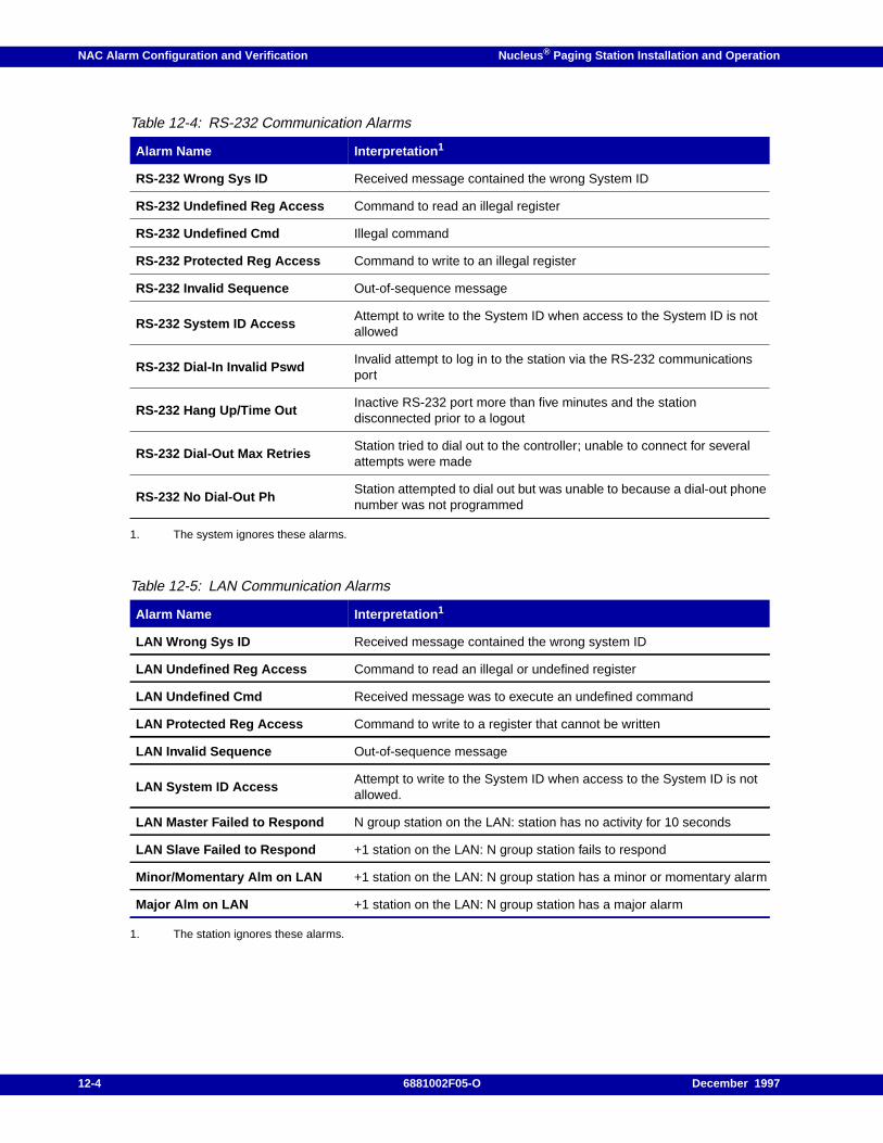
NAC Alarm Configuration and Verification Nucleus ® Paging Station Installation and Operation
1. The system ignores these alarms.
1. The station ignores these alarms.
Table 12-4: RS-232 Communication Alarms
Alarm Name Interpretation 1
RS-232 Wrong Sys ID Received message contained the wrong System ID
RS-232 Undefined Reg Access Command to read an illegal register
RS-232 Undefined Cmd Illegal command
RS-232 Protected Reg Access Command to write to an illegal register
RS-232 Invalid Sequence Out-of-sequence message
RS-232 System ID AccessAttempt to write to the System ID when access to the System ID is notallowed
RS-232 Dial-In Invalid PswdInvalid attempt to log in to the station via the RS-232 communicationsport
RS-232 Hang Up/Time OutInactive RS-232 port more than five minutes and the stationdisconnected prior to a logout
RS-232 Dial-Out Max RetriesStation tried to dial out to the controller; unable to connect for severalattempts were made
RS-232 No Dial-Out PhStation attempted to dial out but was unable to because a dial-out phonenumber was not programmed
Table 12-5: LAN Communication Alarms
Alarm Name Interpretation 1
LAN Wrong Sys ID Received message contained the wrong system ID
LAN Undefined Reg Access Command to read an illegal or undefined register
LAN Undefined Cmd Received message was to execute an undefined command
LAN Protected Reg Access Command to write to a register that cannot be written
LAN Invalid Sequence Out-of-sequence message
LAN System ID AccessAttempt to write to the System ID when access to the System ID is notallowed.
LAN Master Failed to Respond N group station on the LAN: station has no activity for 10 seconds
LAN Slave Failed to Respond +1 station on the LAN: N group station fails to respond
Minor/Momentary Alm on LAN +1 station on the LAN: N group station has a minor or momentary alarm
Major Alm on LAN +1 station on the LAN: N group station has a major alarm
12-4 6881002F05-O December 1997
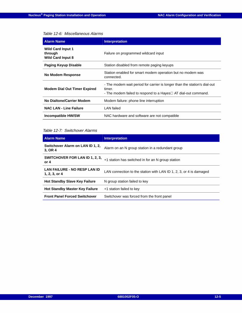
Nucleus ® Paging Station Installation and Operation NAC Alarm Configuration and Verification
Table 12-6: Miscellaneous Alarms
Alarm Name Interpretation
Wild Card Input 1throughWild Card Input 8
Failure on programmed wildcard input
Paging Keyup Disable Station disabled from remote paging keyups
No Modem ResponseStation enabled for smart modem operation but no modem wasconnected.
Modem Dial Out Timer Expired- The modem wait period for carrier is longer than the station’s dial-outtimer.- The modem failed to respond to a Hayes AT dial-out command.
No Dialtone/Carrier Modem Modem failure: phone line interruption
NAC LAN - Line Failure LAN failed
Incompatible HW/SW NAC hardware and software are not compatible
Table 12-7: Switchover Alarms
Alarm Name Interpretation
Switchover Alarm on LAN ID 1, 2,3, OR 4
Alarm on an N group station in a redundant group
SWITCHOVER FOR LAN ID 1, 2, 3,or 4
+1 station has switched in for an N group station
LAN FAILURE - NO RESP LAN ID1, 2, 3, or 4
LAN connection to the station with LAN ID 1, 2, 3, or 4 is damaged
Hot Standby Slave Key Failure N group station failed to key
Hot Standby Master Key Failure +1 station failed to key
Front Panel Forced Switchover Switchover was forced from the front panel
December 1997 6881002F05-O 12-5
NAC Alarm Configuration and Verification Nucleus ® Paging Station Installation and Operation
Alarm Polling
The Advanced Simulcast Controller (ASC) 1500 initiates alarm polling. When the ASC polls thestation, the station reports forward power, reflected power, and alarm status. If the station has activealarms, the ASC reads the alarm information, logs it into the ASC database, and clears the station’salarms (if possible). This method uses the least amount of communication. Alarm polling requiresdigital remote control (DRC). The return path from the station to the ASC can be a dedicated Wildcard,a dial-up phone line (using modems), or over-the-air (RF). If the return path is a dial-in phone line, thestation and the ASC require modems.
Alarm Polling for a Direct Line
Use the following procedure to configure alarm polling if the NAC uses a dedicated phone line foralarm polling:
1. From the READY prompt, press <STN> to access the Station menu.
The display briefly shows the STN menu, then shows the first submenu:
STATION CONTROL SETUP
2. Press <down arrow> to access the DRC SETUP submenu.
3. Press <ENT>.
4. Press <down arrow> to access POLL RESPONSE VIA.
5. Press <ENT>.
The display flashes to show the NAC has entered the edit mode.
6. Press <TOG> to select:
– LINE 2 for Wildcard return path
– RF for over-the-air return path
7. Press <ENT>.
The display stops flashing to show the NAC has stored the value.
8. Press <EXIT> twice to return to the READY prompt.
Polling Setup Procedure (Dial-Up Phone Line Only)
Use the following procedure to configure polling if the NAC uses a dial-up phone line for polling.
1. From the READY prompt, press <OPT2> to access the Options 2 menu.
The display briefly shows the OPT2 menu, then shows the first submenu:
COMM OPTIONS
2. Press <down arrow> to access the RS232 DIAL IN SETUP submenu.
12-6 6881002F05-O December 1997
Nucleus ® Paging Station Installation and Operation NAC Alarm Configuration and Verification
3. Press <ENT>.
4. Press <down arrow> to access POLL RESPONSE VIA.
5. Press <ENT>.
The display flashes to show the NAC has entered the edit mode.
6. Press <TOG> to select:ENABLED .
7. Press <ENT>.
The display stops flashing to show the NAC has stored the value.
8. Press <EXIT> once to return to RS232 DIAL IN SETUP.
9. Press <down arrow> to access ANSWER ON RING #.
10. Press <ENT>.
The display flashes to show the NAC has entered the edit mode.
11. Press <TOG> to select: the correct number of rings.
12. Press <ENT>.
The display stops flashing to show the NAC has stored the value.
13. Press <EXIT> once to return to RS232 DIAL IN SETUP.
14. Press <ENT>.
15. Press <down arrow> to select the modem option. The display shows one of the following:
– NO MODEM CONNECTED
– SMART MODEM CONNECTED
Note: To configure a modem for the NAC station see paragraph, "Modem Connections for Alarm Reporting".
16. Press <ENT>.
The display flashes to show the NAC has entered the edit mode.
17. Press <TOG> to select:SMART MODEM CONNECTED .
18. Press <ENT>.
The display stops flashing to show the NAC has stored the value.
19. Press <EXIT> once to return to RS232 DIAL IN SETUP.
20. Press <down arrow> to access BAUD RATE.
21. Press <ENT>.
December 1997 6881002F05-O 12-7

NAC Alarm Configuration and Verification Nucleus ® Paging Station Installation and Operation
The display flashes to show the NAC has entered the edit mode.
22. Type the correct value for the modem (1200). and press<ENT>.
The display stops flashing to show the NAC has stored the value.
23. Press <EXIT> twice to return to the READY prompt.
12-8 6881002F05-O December 1997
Nucleus ® Paging Station Installation and Operation NAC Alarm Configuration and Verification
Unsolicited Alarm Reporting (UAR)
The station initiates UAR communication with the ASC 1500 when the station discovers an alarm in itsown operation. The station continues reporting an alarm until the ASC acknowledges it. UAR alsorequires DRC. The UAR path from the station to the ASC 1500 must be a dedicated Wildcard or a dial-up phone line (using modems).
In a redundant system, the +1 station initiates UAR communication when it polls a station in the Ngroup and discovers an alarm in the N group station.
If the system uses a dedicated Wildcard, the ASC waits for a pause in paging traffic. During this pause,the ASC interrogates the station for detailed alarm information. If the system uses a dial-up phoneline, the station dials the ASC. The ASC retrieves the alarm information by modem without inhibitingpaging traffic.
Setting up UAR
Note: UAR reduces the need to do alarm polling, but Motorola recommends an occasional full system poll toensure the communications path from the station to the ASC is operational.
The station and the ASC must have Hayes-compatible 1200 baud modems access to dial-up phonelines. When the station sends a UAR to the ASC, the ASC retrieve the alarm information, logs it,attempts to clear the alarm, and hangs up when processing is complete. Other stations that call theASC receive a busy signal during alarm processing. A station that gets a busy signal continues to calluntil it reaches the ASC.
The station modem is external or internal. The external modem is attached to connector J14 on thebackplane with an RS-232 connector. Motorola installs the internal modem (Option C474) duringmanufacturing.
Use the following procedure to configure UAR:
1. From the READY prompt, press <OPT1> to access the Station Options menu.
The display briefly shows the OPT1 menu, then shows the first submenu:
SPECIAL KEY SETUP
2. Press <down arrow> to access the UNSOLICITED ALM REPORTING submenu.
3. Press <ENT>.
The display flashes to show the NAC has entered the edit mode.
4. Press <TOG> to select:ENABLED .
5. Press <ENT>.
The display stops flashing to show the NAC has stored the value.
6. Press <EXIT> once to return to UNSOLICITED ALM REPORTING.
7. Press <down arrow> to access UNSOLICITED ALARMS ON.
December 1997 6881002F05-O 12-9
NAC Alarm Configuration and Verification Nucleus ® Paging Station Installation and Operation
8. Press <ENT>.
The display flashes to show the NAC has entered the edit mode.
9. Press <down arrow> to select ALL .
10. Press <ENT>.
The display stops flashing to show the NAC has stored the value.
11. Press <EXIT> once to return to the UNSOLICITED ALM REPORTING submenu.
12. Press <down arrow> to access REPORT VIA.
13. Press <ENT>.
The display flashes to show the NAC has entered the edit mode.
14. Press <TOG> to select:
– LINE 2 for a dedicated wildcard
– RS232 for a dial-up phone line
15. Press <ENT>.
The display stops flashing to show the NAC has stored the value.
16. Press <EXIT> twice to return to the READY prompt.
17. From the READY prompt, press <STN> to access the Station menu.
The display briefly shows the STN menu, then shows the first submenu:
STN TYPE
18. Press <down arrow> to access the STATION CONTROL SETUP submenu.
19. Press <ENT>.
20. Press <down arrow> to access DRC SETUP.
21. Press <ENT>.
22. Press <down arrow> to access ATC ID.
23. Press <ENT>.
The display flashes to show the NAC has entered the edit mode.
24. Type a value for the ATC ID and press <ENT>.
The display stops flashing to show the NAC has stored the value.
25. Press <EXIT> twice to return to the READY prompt.
12-10 6881002F05-O December 1997
Nucleus ® Paging Station Installation and Operation NAC Alarm Configuration and Verification
Dial-up Phone Line Only
Use the following procedure to configure a dial-up phone line for UAR:
1. From the READY prompt, press <OPT2> to access the Communication Options menu.
The display briefly shows the OPT2 menu, then shows the first submenu:
RS232 DIAL IN SETUP
2. Press <down arrow> to access the RS232 DIAL OUT SETUP submenu.
3. Press <ENT>.
4. Press <down arrow> to access BAUD RATE.
5. Press <ENT>.
The display flashes to show the NAC has entered the edit mode.
6. Type 1200 and press <ENT>.
The display stops flashing to show the NAC has stored the value.
7. Press <EXIT> once to return to the OPT2 menu.
8. Press <down arrow> to access RS232 DIAL OUT SETUP.
9. Press <ENT>.
10. Press <down arrow> to access PHONE NUMBER.
11. Press <ENT>.
The display flashes to show the NAC has entered the edit mode.
12. Type a phone number with as many as 18 digits and press <ENT>.
The display stops flashing to show the NAC has stored the value.
13. Press <down arrow> to access PAUSE AFTER 1ST DIGIT.
14. Press <TOG> to select DISABLED .
15. Press <ENT>.
16. Press <down arrow> to access DIAL OUT VIA.
17. Press <ENT>.
The display flashes to show the NAC has entered the edit mode.
18. Press <TOG> to select:
December 1997 6881002F05-O 12-11
NAC Alarm Configuration and Verification Nucleus ® Paging Station Installation and Operation
– TONE if the telephone network uses Touch-Tone
– PULSE if the network uses rotary-dial pulse
19. Press <ENT>.
The display stops flashing to show the NAC has stored the value.
20. Press <down arrow> to access NUMBER OF ATTTEMPTS BEFORE ALAM.
21. Press <ENT>.
The display flashes to show the NAC has entered the edit mode.
22. Press <TOG> to select:
– DISABLED to disable the RS-232 Dial-Out Max Retries Comm Alarm feature
– BEFORE ALM 2 to select two failed UAR retries
– BEFORE ALM 5 to select five failed UAR retries
– BEFORE ALM 10 to select ten failed UAR retries
23. Press <ENT>.
The display stops flashing to show the NAC has stored the value.
24. Press <EXIT> to return to the OPT2 menu and the RS232 DIALIN SETUP submenu.
25. Press <ENT>.
26. Press <down arrow> to select the modem option. The display shows one of the following:
– NO MODEM CONNECTED
– SMART MODEM CONNECTED
Note: To configure a modem for the NAC station see paragraph, "Modem Connections for Alarm Reporting".
27. Press <ENT>.
The display flashes to show the NAC has entered the edit mode.
28. Press <TOG> to select:SMART MODEM CONNECTED .
29. Press <ENT>.
The display stops flashing to show the NAC has stored the value.
30. Press <EXIT> twice to return to the READY prompt.
12-12 6881002F05-O December 1997
Nucleus ® Paging Station Installation and Operation NAC Alarm Configuration and Verification
ASCII Diagnostics
The NAC board transmits ASCII text communications through an RS-232 port for display on a VT100terminal, simulating the station’s front-panel keypad, display, and LEDs. A technician can use aterminal to interrogate the NAC, access parameter and function menus, and display front panel LEDsin real time. This connection requires modems.
NAC supports ASCII text communications through the RS-232 port, J14. ASCII communicationsimulates the station’s front-panel keypad, display, and LEDs. This connection uses modems. Thetechnician can dial into the NAC from a remote location and access all station parameters. ASCIIdiagnostics also display front panel LEDs in real time.
Modem Setup
The station modem is external or internal. An external modem uses J14 on the backplane with anRS232 connector. An internal modem is installed during manufacturing.
Use the following procedure during initial installation to configure ASCII diagnostics from the frontpanel:
1. From the READY prompt, press <OPT2> to access the Communication Options menu.
The display briefly shows the OPT2 menu, then shows the first submenu:
COMM OPTIONS
2. Press <down arrow> to access the RS232 DIAL OUT SETUP submenu.
3. Press <ENT>.
The display flashes to show the NAC has entered the edit mode.
4. Type 1200 and press <ENT> to configure this rate.
The display stops flashing to show the NAC has stored the value.
5. Press <down arrow> to access RS232 DIAL IN SETUP.
6. Press <ENT>.
The display flashes to show the NAC has entered the edit mode.
7. Press <TOG> to select ENABLED .
8. Press <ENT>.
9. Press <down arrow> to access ANSWER ON RING #.
10. Press <ENT>.
The display flashes to show the NAC has entered the edit mode.
11. Press <TOG> to select a value in the range 1 through 4.
December 1997 6881002F05-O 12-13
NAC Alarm Configuration and Verification Nucleus ® Paging Station Installation and Operation
12. Press <ENT>.
The display stops flashing to show the NAC has stored the value.
13. Press <EXIT> to access RS232 DIAL IN SETUP.
14. Press <down arrow> to select the modem option. The display shows one of the following:
– NO MODEM CONNECTED
– SMART MODEM CONNECTED
Note: To configure a modem for the NAC station see paragraph, "Modem Connections for Alarm Reporting".
15. Press <ENT>.
The display flashes to show the NAC has entered the edit mode.
16. Press <TOG> to select:SMART MODEM CONNECTED .
17. Press <ENT>.
The display stops flashing to show the NAC has stored the value.
18. Press <EXIT> twice to return to the READY prompt.
19. From the READY prompt, press <DIS> to access the DISABLE ACCESS menu.
The display briefly shows the DIS menu, then shows the first submenu:
ACCESS
20. Press <ENT>.
The display flashes to show the NAC has entered the edit mode.
21. Press <TOG> to select ENABLED .
22. Press <ENT>.
The display stops flashing to show the NAC has stored the value.
23. Press <EXIT> once to return to the READY prompt.
VT100 Dumb Terminal Configuration
Use the following procedure to configure a VT100 terminal:
1. Configure the RS-232 serial communications port set for asynchronous communication with 8data bits, 1 stop bit, and no parity.
2. Configure the modem for 1200 baud.
3. Configure the serial port in full duplex mode with no local echo.
12-14 6881002F05-O December 1997
Nucleus ® Paging Station Installation and Operation NAC Alarm Configuration and Verification
4. Configure the VT100 to use the VT100 protocol.
5. Configure the terminal width for 80 characters.
6. If the VT100 dumb terminal uses an underline cursor and audible beeps enable them.
7. Connect the terminal end of the cable to the terminal Datacom serial port.
8. Connect the DB-25 mail connector to J61.
Personal Computer as a Terminal Emulator
A personal computer used as the remote terminal with a VT100 emulator software package. Thiscomputer must meet the following requirements:
• IBM PC, XT, AT, PS/2 or compatible
• MS-DOS or PC-DOS version 2.0 or later operating system
• RS-232 serial communications port set for asynchronous communication with 8 data bits, 1 stopbit, and no parity
• 1200 baud rate
• Serial port in full duplex mode
Use the following procedure to connect and configure the PC:
1. Connect the DB-25 cable to the COM1 port on the PC.
2. Connect the DB-25 cable to J61 on the station.
3. Boot the terminal emulation program. Type:
<program command + CR>
4. Press <ALT + P> to configure port settings.
5. Configure the computer for the following communication attributes:
– 1200 baud
– 8 data bits
– 1 stop bit
– no parity
6. Select the COM port.
7. Press <ESC>.
8. Type <ALT + S> for the setup utility.
9. In the setup utility, select Choose Terminal Options .
December 1997 6881002F05-O 12-15
NAC Alarm Configuration and Verification Nucleus ® Paging Station Installation and Operation
10. Configure the following characteristics:
– Terminal emulation = VT100
– Full duplex
– Terminal width = 80 characters
11. Press <Esc>.
12. Select Display/Sound Options.
13. Turn on sound effects and alarm sound.
14. Select line as the cursor type.
15. Press <ESC> twice.
16. Select Protocol Options.
17. Disable Local Echo.
18. Press <ESC> several times to exit configuration.
Apple Macintosh Computer (VT100 Emulator) Setup
An Apple Macintosh computer used as the remote terminal with a VT100 emulator software packagemust meet the following requirements:
• Apple Macintosh operating system
• RS-232 serial communications port set for asynchronous communication with 8 data bits, 1 stopbit, and no parity
• 1200 baud
• Serial port in full duplex mode
Note: This connection requires an Apple Macintosh IIe modem-8 cable (part number A2C0311).
Use the following procedure to configure the Apple Macintosh computer.
Note: The Product Group has qualified MicroPhone software for Apple Macintosh computers. Thisprocedure is based on MicroPhone software.
1. Boot MicroPhone.
2. Double click the mouse on the MicroPhone icon.
3. Move the cursor to the Settings menu. Hold down the mouse button.
The system displays the Settings menu.
4. Select the Communications category and release the mouse button.
12-16 6881002F05-O December 1997
Nucleus ® Paging Station Installation and Operation NAC Alarm Configuration and Verification
The software displays the Communications screen.
5. Configure the following items:
– 1200 baud
– 8 data bits
– 1 stop bit
– No parity
– Activate phone connection port
– Deactivate hardware handshaking
6. Click on OK.
7. Move the cursor to the Settings menu item and hold down the mouse button.
8. Select the Terminal category and release the mouse button. The software displays the Terminalscreen.
9. Set the following by clicking on the mouse button:
– VT VT102 emulation
– ANSI mode
– Column width =80
– 9-point or 12-point font size
– Activate underline cursor shape
– Deactivate local echo
– Deactivate auto line feed
– Deactivate auto wraparound
– Activate backspace key
10. Click on OK.
Dialing the Station with the Remote Terminal
Note: Save all terminal configuration data before attempting to dial the station for the first time.
Use the following procedure to dial into the station:
1. Type the following Hayes AT command:
ATX4E1V1Q0 <CR>
2. Type the following command:
ATDT####### <CR>
The terminal responds:
Connect
The station requires approximately five seconds to make the connection.
December 1997 6881002F05-O 12-17
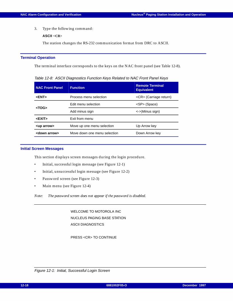
NAC Alarm Configuration and Verification Nucleus ® Paging Station Installation and Operation
3. Type the following command:
ASCII <CR>
The station changes the RS-232 communication format from DRC to ASCII.
Terminal Operation
The terminal interface corresponds to the keys on the NAC front panel (see Table 12-8).
Initial Screen Messages
This section displays screen messages during the login procedure.
• Initial, successful login message (see Figure 12-1)
• Initial, unsuccessful login message (see Figure 12-2)
• Password screen (see Figure 12-3)
• Main menu (see Figure 12-4)
Note: The password screen does not appear if the password is disabled.
Figure 12-1: Initial, Successful Login Screen
Table 12-8: ASCII Diagnostics Function Keys Related to NAC Front Panel Keys
NAC Front Panel FunctionRemote TerminalEquivalent
<ENT> Process menu selection <CR> (Carriage return)
<TOG>Edit menu selection <SP> (Space)
Add minus sign <->)Minus sign)
<EXIT> Exit from menu
<up arrow> Move up one menu selection Up Arrow key
<down arrow> Move down one menu selection Down Arrow key
WELCOME TO MOTOROLA INC
NUCLEUS PAGING BASE STATION
ASCII DIAGNOSTICS
PRESS <CR> TO CONTINUE
12-18 6881002F05-O December 1997
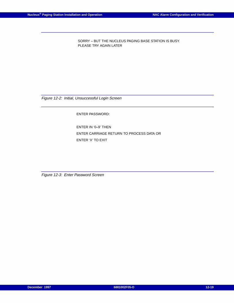
Nucleus ® Paging Station Installation and Operation NAC Alarm Configuration and Verification
Figure 12-2: Initial, Unsuccessful Login Screen
Figure 12-3: Enter Password Screen
SORRY – BUT THE NUCLEUS PAGING BASE STATION IS BUSY.PLEASE TRY AGAIN LATER
ENTER PASSWORD:
ENTER IN ‘0–9’ THEN
ENTER CARRIAGE RETURN TO PROCESS DATA OR
ENTER ‘X’ TO EXIT
December 1997 6881002F05-O 12-19
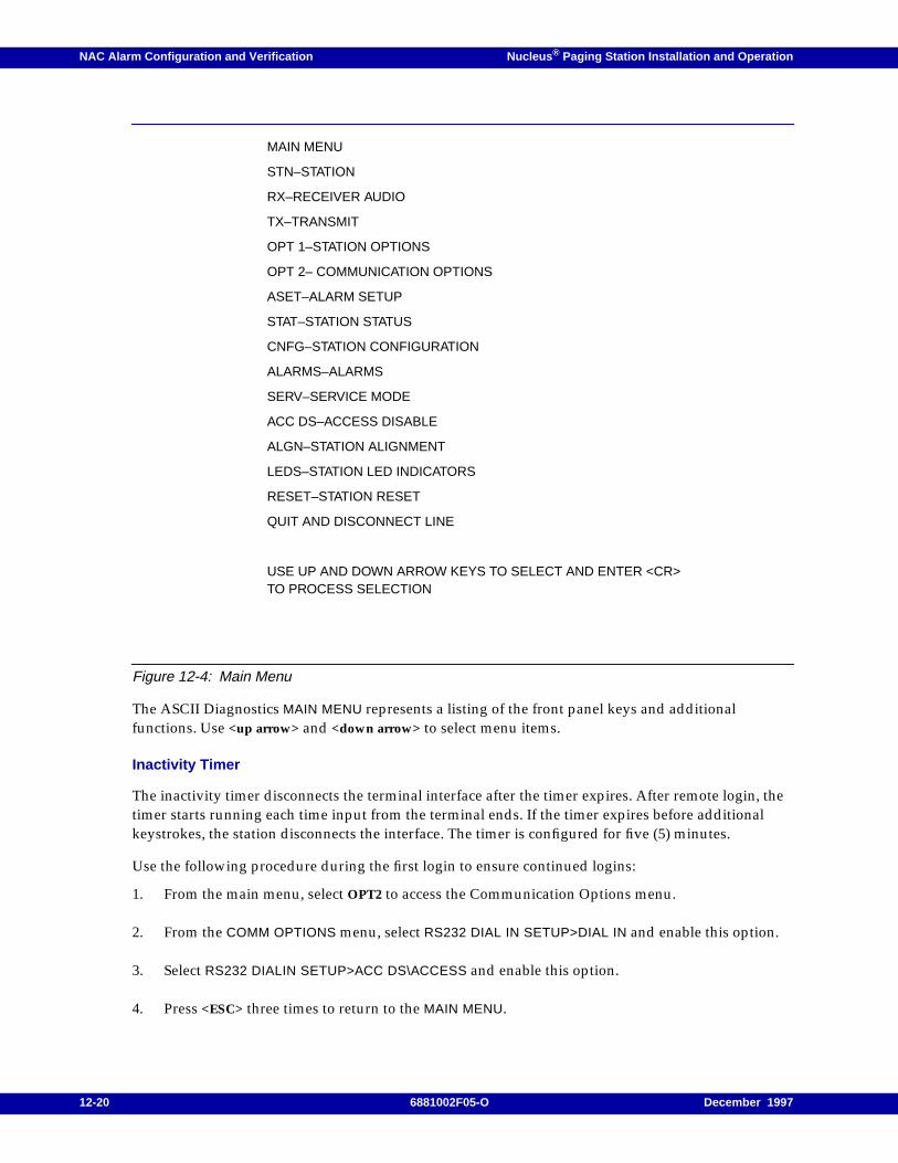
NAC Alarm Configuration and Verification Nucleus ® Paging Station Installation and Operation
Figure 12-4: Main Menu
The ASCII Diagnostics MAIN MENU represents a listing of the front panel keys and additionalfunctions. Use <up arrow> and <down arrow> to select menu items.
Inactivity Timer
The inactivity timer disconnects the terminal interface after the timer expires. After remote login, thetimer starts running each time input from the terminal ends. If the timer expires before additionalkeystrokes, the station disconnects the interface. The timer is configured for five (5) minutes.
Use the following procedure during the first login to ensure continued logins:
1. From the main menu, select OPT2 to access the Communication Options menu.
2. From the COMM OPTIONS menu, select RS232 DIAL IN SETUP>DIAL IN and enable this option.
3. Select RS232 DIALIN SETUP>ACC DS\ACCESS and enable this option.
4. Press <ESC> three times to return to the MAIN MENU.
MAIN MENU
STN–STATION
RX–RECEIVER AUDIO
TX–TRANSMIT
OPT 1–STATION OPTIONS
OPT 2– COMMUNICATION OPTIONS
ASET–ALARM SETUP
STAT–STATION STATUS
CNFG–STATION CONFIGURATION
ALARMS–ALARMS
SERV–SERVICE MODE
ACC DS–ACCESS DISABLE
ALGN–STATION ALIGNMENT
LEDS–STATION LED INDICATORS
RESET–STATION RESET
QUIT AND DISCONNECT LINE
USE UP AND DOWN ARROW KEYS TO SELECT AND ENTER <CR>TO PROCESS SELECTION
12-20 6881002F05-O December 1997

Nucleus ® Paging Station Installation and Operation NAC Alarm Configuration and Verification
Wildcard Inputs/Outputs
The NAC uses the Wildcard interface to sense an external logic switching states (wildcard input) or tocontrol an external peripheral device (wildcard output). Wildcard inputs are TTL inputs. When awildcard input is active, the wildcard alarm triggers. The controller reads these triggers duringdiagnostic polling or a UAR. Wildcard outputs are open-collector transistor outputs. When an outputsignal is active, the corresponding open collector goes low (ON). The front panel provides programingcontrol of each wildcard input or output.
Wireline inputs and outputs are control signal interfaces used as follows:
• External logic switch states (wild card inputs)
• External peripheral device control (wild card output)
Note: When the transmitter is in TRC mode, you cannot modify these parameters. The wildcard outputs willact as outputs for predetermined alarms and status indicators.
Use the following procedure to enable inputs and outputs:
1. From the READY prompt, press <OPT1> to access the Station Options menu.
The display briefly shows the OPT1 menu, then shows the first submenu:
SPECIAL KEY SETUP
2. Press <down arrow> to access the WILD CARD INPUT SETUP submenu
3. Press <ENT>.
The display flashes to show the NAC has entered the edit mode.
4. Press <TOG> to configure the input.
5. Press <ENT>.
The display stops flashing to show the NAC has stored the value.
6. Press <down arrow> to access the next Wild Card input.
7. Repeat Step 2 through Step 6 to configure the wildcard inputs.
8. Press <EXIT> to return to the READY prompt.
9. From the READY prompt, press <OPT1> to access the Station Options menu.
The display briefly shows the OPT1 menu, then shows the first submenu:
SPECIAL KEY SETUP
10. Press <down arrow> to access the WILD CARD OUTPUT SETUP submenu.
11. Press <ENT>.
The display flashes to show the NAC has entered the edit mode.
December 1997 6881002F05-O 12-21
NAC Alarm Configuration and Verification Nucleus ® Paging Station Installation and Operation
12. Press <TOG> to configure the input.
13. Press <ENT>.
The display stops flashing to show the NAC has stored the value.
14. Press <down arrow> to access the next wildcard input.
15. Repeat Step 10 through Step 14 to configure the wildcard inputs.
16. Press <EXIT> to return to the READY prompt.
12-22 6881002F05-O December 1997
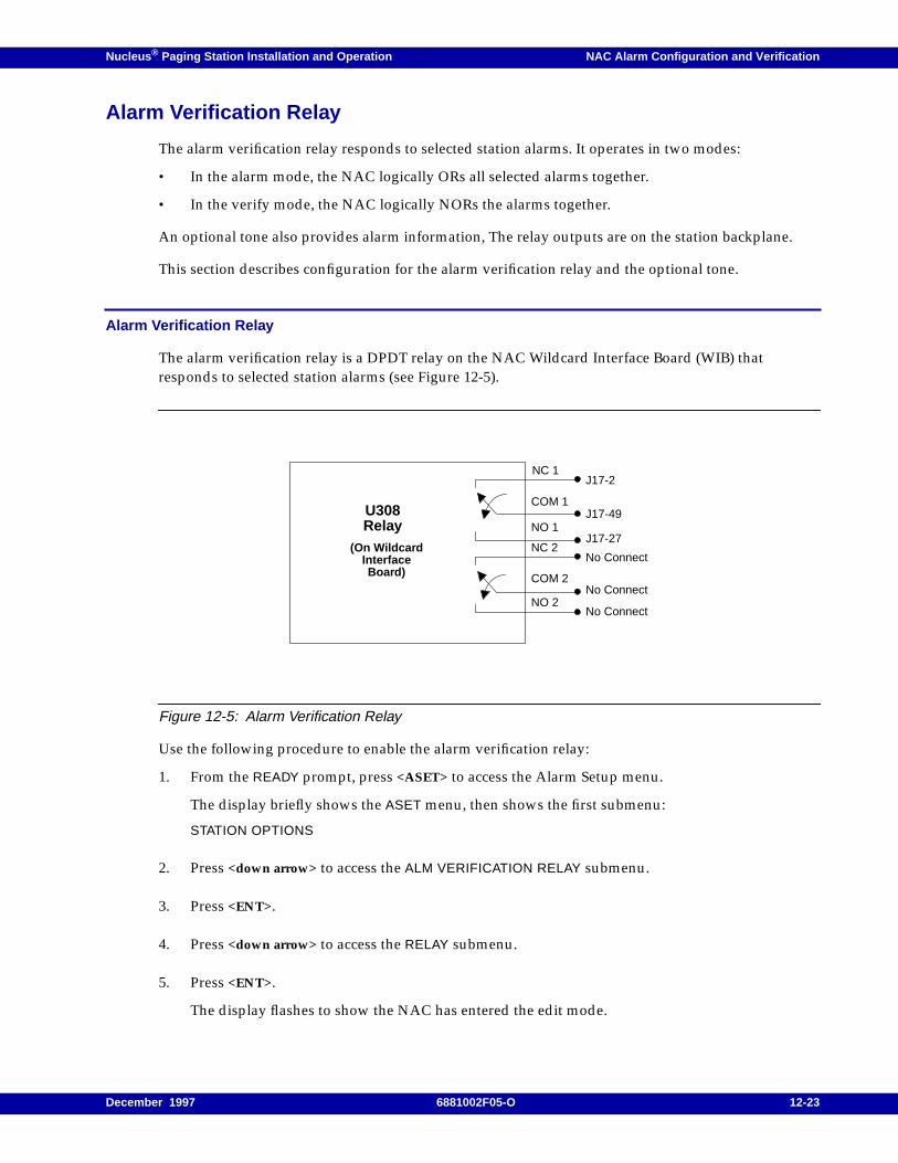
Nucleus ® Paging Station Installation and Operation NAC Alarm Configuration and Verification
Alarm Verification Relay
The alarm verification relay responds to selected station alarms. It operates in two modes:
• In the alarm mode, the NAC logically ORs all selected alarms together.
• In the verify mode, the NAC logically NORs the alarms together.
An optional tone also provides alarm information, The relay outputs are on the station backplane.
This section describes configuration for the alarm verification relay and the optional tone.
Alarm Verification Relay
The alarm verification relay is a DPDT relay on the NAC Wildcard Interface Board (WIB) thatresponds to selected station alarms (see Figure 12-5).
Figure 12-5: Alarm Verification Relay
Use the following procedure to enable the alarm verification relay:
1. From the READY prompt, press <ASET> to access the Alarm Setup menu.
The display briefly shows the ASET menu, then shows the first submenu:
STATION OPTIONS
2. Press <down arrow> to access the ALM VERIFICATION RELAY submenu.
3. Press <ENT>.
4. Press <down arrow> to access the RELAY submenu.
5. Press <ENT>.
The display flashes to show the NAC has entered the edit mode.
U308Relay
NC 1
COM 1
NO 1
NC 2
COM 2
NO 2
(On WildcardInterfaceBoard)
J17-2
J17-49
J17-27
No Connect
No Connect
No Connect
December 1997 6881002F05-O 12-23
NAC Alarm Configuration and Verification Nucleus ® Paging Station Installation and Operation
6. Press <TOG> to select ALARM MODE .
7. Press <ENT>.
The display stops flashing to show the NAC has stored the value.
8. Press <down arrow> to access ALM VERIFICATION RELAY.
9. Press <ENT>.
The display shows the first alarm:
OPT ALARM
The display flashes to show the NAC has entered the edit mode.
10. Press <TOG> to select ENABLED .
11. Press <ENT>.
The display stops flashing to show the NAC has stored the value.
12. Press <down arrow> to access the rest of the alarms:
– REDUNDANCY SWITCH OCCURRED
– STN ALARM
– PA FAULT 1
– PA FAULT 2
– PA CUTBACK
– SYNTH OUT OF LOCK
– LOW FORWARD POWER
– HIGH REFLECTED POWER
– HIGH VSWR
– TX IN LIMIT
– HIGH TRAY TEM
– BATTERY REVERT
– STN EXECUTED RESET
– DIAG FAILURE
– SYSTEM TIMER
13. Repeat Step 10 through Step 12 to enable the rest of the alarms.
14. Press <ENT>.
15. Press <up arrow>.
16. The display shows the first MISC ALARM.
WILD CARD INPUT 1
17. Press <ENT>.
12-24 6881002F05-O December 1997
Nucleus ® Paging Station Installation and Operation NAC Alarm Configuration and Verification
The display flashes to show the NAC has entered the edit mode.
18. Press <TOG> to enable this alarm.
19. Press<ENT>.
The display stops flashing to show the NAC has stored the value.
20. Press <down arrow> to access the rest of the alarms:
– WILD CARD INPUT 2
– WILD CARD INPUT 3
– WILD CARD INPUT 4
– WILD CARD INPUT 5
– WILD CARD INPUT 6
– WILD CARD INPUT 7
– WILD CARD INPUT 8
– PAGING KEYUP DISABLE
– NO MODEM RESPONSE
– MODEM DIAL OUT TIMER EXPIRED
– NO DIALTONE/CARRIER MODEM
– NAC LAN - LINE FAILURE
– EE DATA MODIFIED
21. Repeat Step 18 through Step 20 to enable the rest of the alarms.
22. Press <EXIT> twice to return to the READY prompt.
Alarm Verification Tone
In cases where an alarm or verification tone is preferred to a relay closure, the NAC encodes a 387 Hztone to Line 2 when all alarms are inactive. Use the following procedure to enable this tone:
1. From the station backplane, connect pin 4 to pin 29 on the orange connector.
2. From the READY prompt, press <OPT1> to access the Station Options menu.
The display briefly shows the OPT1 menu, then shows the first submenu:
SPECIAL KEY SETUP
3. Press <down arrow> to access the 387 VERIFICATION TONe submenu.
4. Press <ENT>.
The display flashes to show the NAC has entered the edit mode.
5. Press <TOG> to select ENABLED .
6. Press <ENT>.
December 1997 6881002F05-O 12-25

NAC Alarm Configuration and Verification Nucleus ® Paging Station Installation and Operation
The display stops flashing to show the NAC has stored the value.
7. Press <EXIT> twice to return to the READY prompt.
12-26 6881002F05-O December 1997
Nucleus ® Paging Station Installation and Operation NAC Alarm Configuration and Verification
Modem Connections for Alarm Reporting
This section describes the modems required for alarm reporting.
Modem Requirements
Modems provide one communication option for alarm polling and UARs. ASCII diagnostic requiremodems for the communication link between the NAC and the terminal or computer (unless theterminal/computer is connected to the station locally).
The station and terminal/computer modems must meet the following communications requirements:
• The data format is serial, binary, and asynchronous, with 8 data bits, 1 stop bit, and no parity.
• The dialing is Touch-Tone or rotary-dial pulse dialing.
• The data rate is 1200 baud.
• The port interface follows an RS-232C standard.
• The modem must accept Hayes “AT” software commands (this includes “AT” S-Registercommands).
• The modem is internally set or can be configured to ignore the data terminal ready (DTR) pinsignal.
• The modem is internally set or can be configured to assume that the data carrier detect (DCD) pinsignal is always present.
The station accepts an internal or external modem. Motorola installs the internal modem option, C474,during manufacturing. Attach an external modem to connector J14 on the backplane.
The following modems are acceptable as a station external modem or as a terminal/computer modem:
• Hayes Smartmodem 2400B–This modem does not require dual in-line package (DIP) switchsettings. The station configures the modem automatically.
• UDS 2440–This modem has front panel configuration with a liquid crystal display (LCD) screenand three push-buttons (see Table 12-9 for configuration).
• Practical Peripherals PM1200SA Mini–This modem has DIP switches for configuration (seeTable 12-10).
• US Robotics Sportster 2400–This modem has DIP switches for configuration (see Table 12-11).
December 1997 6881002F05-O 12-27
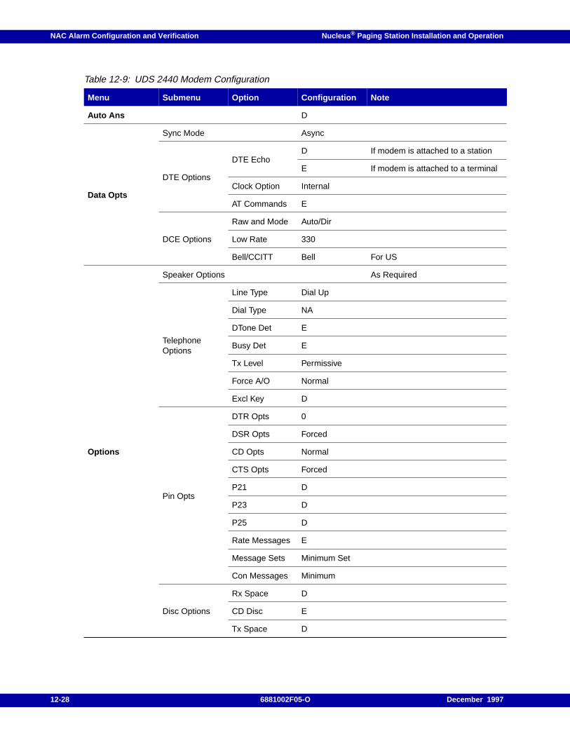
NAC Alarm Configuration and Verification Nucleus ® Paging Station Installation and Operation
Table 12-9: UDS 2440 Modem Configuration
Menu Submenu Option Configuration Note
Auto Ans D
Data Opts
Sync Mode Async
DTE Options
DTE EchoD If modem is attached to a station
E If modem is attached to a terminal
Clock Option Internal
AT Commands E
DCE Options
Raw and Mode Auto/Dir
Low Rate 330
Bell/CCITT Bell For US
Options
Speaker Options As Required
TelephoneOptions
Line Type Dial Up
Dial Type NA
DTone Det E
Busy Det E
Tx Level Permissive
Force A/O Normal
Excl Key D
Pin Opts
DTR Opts 0
DSR Opts Forced
CD Opts Normal
CTS Opts Forced
P21 D
P23 D
P25 D
Rate Messages E
Message Sets Minimum Set
Con Messages Minimum
Disc Options
Rx Space D
CD Disc E
Tx Space D
12-28 6881002F05-O December 1997
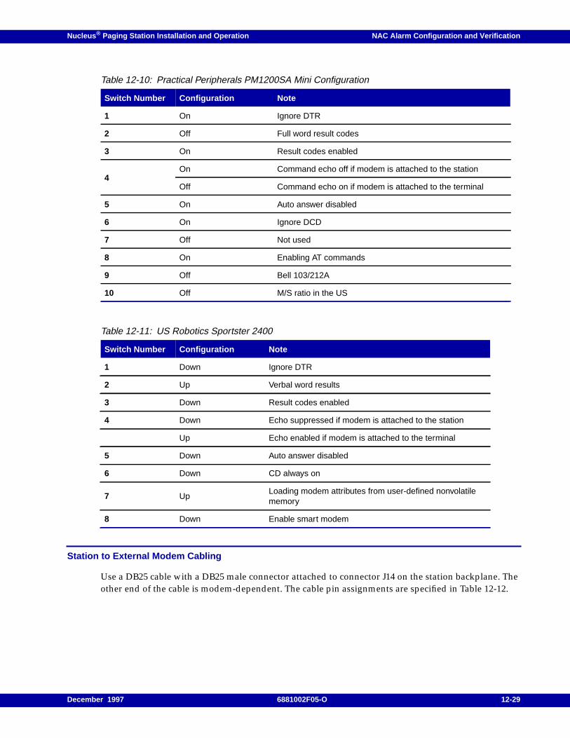
Nucleus ® Paging Station Installation and Operation NAC Alarm Configuration and Verification
Station to External Modem Cabling
Use a DB25 cable with a DB25 male connector attached to connector J14 on the station backplane. Theother end of the cable is modem-dependent. The cable pin assignments are specified in Table 12-12.
Table 12-10: Practical Peripherals PM1200SA Mini Configuration
Switch Number Configuration Note
1 On Ignore DTR
2 Off Full word result codes
3 On Result codes enabled
4On Command echo off if modem is attached to the station
Off Command echo on if modem is attached to the terminal
5 On Auto answer disabled
6 On Ignore DCD
7 Off Not used
8 On Enabling AT commands
9 Off Bell 103/212A
10 Off M/S ratio in the US
Table 12-11: US Robotics Sportster 2400
Switch Number Configuration Note
1 Down Ignore DTR
2 Up Verbal word results
3 Down Result codes enabled
4 Down Echo suppressed if modem is attached to the station
Up Echo enabled if modem is attached to the terminal
5 Down Auto answer disabled
6 Down CD always on
7 UpLoading modem attributes from user-defined nonvolatilememory
8 Down Enable smart modem
December 1997 6881002F05-O 12-29
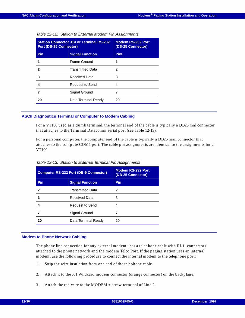
NAC Alarm Configuration and Verification Nucleus ® Paging Station Installation and Operation
ASCII Diagnostics Terminal or Computer to Modem Cabling
For a VT100 used as a dumb terminal, the terminal end of the cable is typically a DB25 mal connectorthat attaches to the Terminal Datacomm serial port (see Table 12-13).
For a personal computer, the computer end of the cable is typically a DB25 mail connector thatattaches to the compute COM1 port. The cable pin assignments are identical to the assignments for aVT100.
Modem to Phone Network Cabling
The phone line connection for any external modem uses a telephone cable with RJ-11 connectorsattached to the phone network and the modem Telco Port. If the paging station uses an internalmodem, use the following procedure to connect the internal modem to the telephone port:
1. Strip the wire insulation from one end of the telephone cable.
2. Attach it to the J61 Wildcard modem connector (orange connector) on the backplane.
3. Attach the red wire to the MODEM + screw terminal of Line 2.
Table 12-12: Station to External Modem Pin Assignments
Station Connector J14 or Terminal RS-232Port (DB-25 Connector)
Modem RS-232 Port(DB-25 Connector)
Pin Signal Function Pint
1 Frame Ground 1
2 Transmitted Data 2
3 Received Data 3
4 Request to Send 4
7 Signal Ground 7
20 Data Terminal Ready 20
Table 12-13: Station to External Terminal Pin Assignments
Computer RS-232 Port (DB-9 Connector)Modem RS-232 Port(DB-25 Connector)
Pin Signal Function Pin
2 Transmitted Data 2
3 Received Data 3
4 Request to Send 4
7 Signal Ground 7
20 Data Terminal Ready 20
12-30 6881002F05-O December 1997

Nucleus ® Paging Station Installation and Operation NAC Alarm Configuration and Verification
4. Attach the green wire to the MODEM - screw terminal of Line 2 on the Wildcard interfaceterminal block.
December 1997 6881002F05-O 12-31
NAC Alarm Configuration and Verification Nucleus ® Paging Station Installation and Operation
Local Connection Without Modems
Use the following procedure to create a local connection without modems:
Note: The terminal does not display the typed commands.
The NAC cannot perform UAR without a modem.
1. Use the same cable that attaches the VT100 terminal to the external modem. Use a modemadapter (product number 5805092T01) to the DB-25 male connector.
2. Attach one end of the converted cable to the VT100 terminal serial port.
3. Attach the other end to J14 on the station’s backplane.
4. Configure the terminal (see paragraph, "Station to External Modem Cabling"). The exception isthat the terminal port setting must be NAC.
5. Configure the terminal for the following:
– smart modem connected
– alarms disabled from the ASC
12-32 6881002F05-O December 1997
Nucleus ® Paging Station Installation and Operation NAC Alarm Configuration and Verification
Resetting Alarms
This section describes station and alarm reset procedure.
Note: When a n alarm title appears on the display, press <up arrow> or <down arrow> to display otheralarms. The display shows alarms that are set.
Use the following procedure to clear an alarm:
1. From the READY prompt, press <ALMS> to access the Alarm menu.
The display briefly shows the ALMS menu, then shows the first submenu:
STATION ALMS
2. Press <ENT>.
The display shows the first active alarm.
3. Press <ENT> to clear the alarm.
The display shows the next active alarm.
4. Repeat Step 3 to clear all active alarms.
5. Press <EXIT> to return to the READY prompt.
December 1997 6881002F05-O 12-33
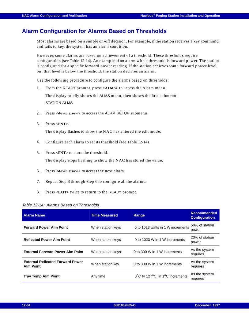
NAC Alarm Configuration and Verification Nucleus ® Paging Station Installation and Operation
Alarm Configuration for Alarms Based on Thresholds
Most alarms are based on a simple on-off decision. For example, if the station receives a key commandand fails to key, the system has an alarm condition.
However, some alarms are based on achievement of a threshold. These thresholds requireconfiguration (see Table 12-14). An example of an alarm with a threshold is forward power. The stationis configured for a specific forward power reading. If the station achieves some forward power level,but that level is below the threshold, the station declares an alarm.
Use the following procedure to configure the alarms based on thresholds:
1. From the READY prompt, press <ALMS> to access the Alarm menu.
The display briefly shows the ALMS menu, then shows the first submenu:
STATION ALMS
2. Press <down arrow> to access the ALRM SETUP submenu.
3. Press <ENT>.
The display flashes to show the NAC has entered the edit mode.
4. Configure each alarm to set its threshold (see Table 12-14).
5. Press <ENT> to store the threshold.
The display stops flashing to show the NAC has stored the value.
6. Press <down arrow> to access the next alarm.
7. Repeat Step 3 through Step 6 to configure all the alarms.
8. Press <EXIT> twice to return to the READY prompt.
Table 12-14: Alarms Based on Thresholds
Alarm Name Time Measured RangeRecommendedConfiguration
Forward Power Alm Point When station keys 0 to 1023 watts in 1 W increments50% of stationpower
Reflected Power Alm Point When station keys 0 to 1023 W in 1 W increments20% of stationpower
External Forward Power Alm Point When station keys 0 to 300 W in 1 W incrementsAs the systemrequires
External Reflected Forward PowerAlm Point
When station key 0 to 300 W in 1 W incrementsAs the systemrequires
Tray Temp Alm Point Any time 0oC to 127oC, in 1oC incrementsAs the systemrequires
12-34 6881002F05-O December 1997
Nucleus ® Paging Station Installation and Operation NAC Alarm Configuration and Verification
Alarms for N+1 Redundancy
If this station is part of an N+1 redundancy system, use the following procedure to set the alarms.
1. From the READY prompt, press <ALMS> to access the Alarm menu.
The display briefly shows the ALMS menu, then shows the first submenu:
STATION ALMS
2. Press <down arrow> to access the ALRM SETUP submenu.
3. Press <ENT>.
The display flashes to show the NAC has entered the edit mode.
4. Press <ENT>. The display shows the first alarm:
REDUN SWITCHOVER ALARM
5. Press <TOG> to select the alarm level:
– CRITICAL (high priority)
– GENERAL (low priority)
– NOT SELECTED
6. Press <ENT>.
The display stops flashing to show the NAC has stored the value.
7. Press <down arrow> to access the rest of the alarms:
– PA FAULT 1
– PA FAULT 2
– PA CUTBACK
– SYNTH OUT OF LOCK
– LOW FORWARD POWER
– HIGH REFLECTED POWER
– HIGH VSWR
– TX IN LIMIT
– HIGH TRAY TEMP
– BATTERY REVERT
– STN EXECUTED RESET
– DIAG FAILURE
– SYSTEM TIMER
8. Repeat Step 5 through Step 7 to configure the alarms.
9. Press <EXIT> twice to return to the READY prompt.
December 1997 6881002F05-O 12-35

NAC Alarm Configuration and Verification Nucleus ® Paging Station Installation and Operation
12-36 6881002F05-O December 1997
Nucleus ® Paging Station Installation and Operation / Chapter 13
Replacing Modules 13
When troubleshooting identifies a faulty module in the Nucleus paging station, replacing it with aknown good module restores the station to proper operation. This chapter describes replacementprocedures and required post-replacement adjustments or programming. This chapter contains thefollowing information:
General Replacement Information, 13-2Antistatic Precautions, 13-2Mechanical Restraints, 13-3Gold-plated Connector Contacts, 13-3Validating Repairs, 13-4
Replacing the Power Amplifier (PA) in a Standard Power Station, 13-5Replacement Procedure, 13-5Post-replacement Optimization Procedure, 13-7
Replacing the Power Amplifier (PA) in a Standard Power Station, 13-8Replacement Procedure, 13-8Post-replacement optimization procedure, 13-9
Replacing the Power Supply, 13-10Replacement Procedure, 13-10Post-replacement Optimization Procedure, 13-11
Replacing the Station Control Board and Exciter as a Matched Pair, 13-12Configuration Settings, 13-12Replacing the Exciter, 13-12Replacing the Station Control Board, 13-13Post-replacement Optimization Procedure, 13-14
Backplane, 13-15Replacement Procedure, 13-15Post-replacement Optimization Procedure, 13-15
Note: This chapter does not describe replacement procedures for the following modules:- Internal Network Interface Unit (NIU)- Wildcard Interface Board (WIB)- Receiver module- Reference module
The replacement procedures for these modules appear in the appropriate appendices.
December 1997 6881002F05-O 13-1
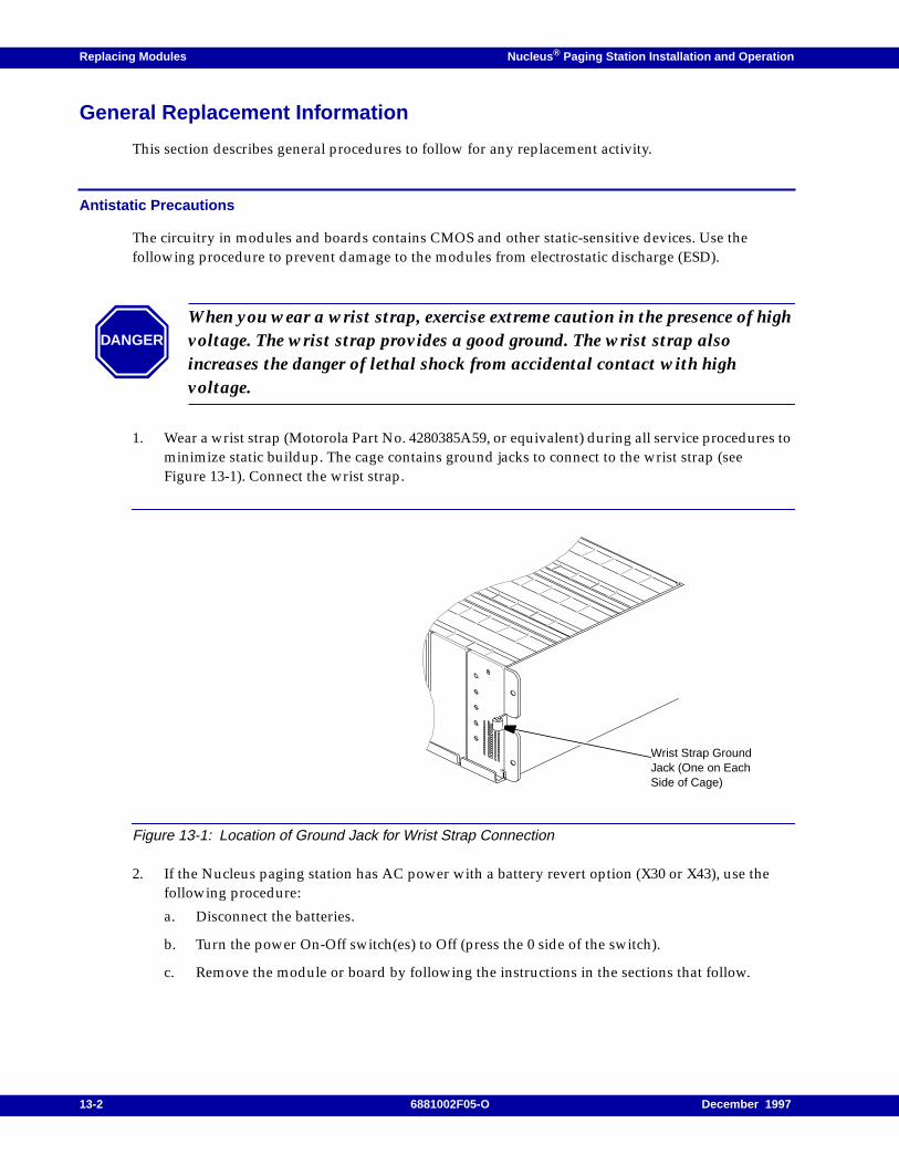
Replacing Modules Nucleus ® Paging Station Installation and Operation
General Replacement Information
This section describes general procedures to follow for any replacement activity.
Antistatic Precautions
The circuitry in modules and boards contains CMOS and other static-sensitive devices. Use thefollowing procedure to prevent damage to the modules from electrostatic discharge (ESD).
1. Wear a wrist strap (Motorola Part No. 4280385A59, or equivalent) during all service procedures tominimize static buildup. The cage contains ground jacks to connect to the wrist strap (seeFigure 13-1). Connect the wrist strap.
Figure 13-1: Location of Ground Jack for Wrist Strap Connection
2. If the Nucleus paging station has AC power with a battery revert option (X30 or X43), use thefollowing procedure:
a. Disconnect the batteries.
b. Turn the power On-Off switch(es) to Off (press the 0 side of the switch).
c. Remove the module or board by following the instructions in the sections that follow.
DANGER
When you wear a wrist strap, exercise extreme caution in the presence of highvoltage. The wrist strap provides a good ground. The wrist strap alsoincreases the danger of lethal shock from accidental contact with highvoltage.
Wrist Strap GroundJack (One on EachSide of Cage)
13-2 6881002F05-O December 1997
Nucleus ® Paging Station Installation and Operation Replacing Modules
3. Keep each spare modules in an antistatic bag for storage and transporting. Pack modules inantistatic materials to ship them.
4. To restore power, use the following procedure:
a. Turn the power On-Off switch(es) to On (press the 1 side of the switch).
b. Reconnect the batteries.
Mechanical Restraints
Each module slides on rails built into the cage. Each module plugs into the backplane. Each module isheld in place by a mounting screw at the very top of the front panel and a mounting screw at the verybottom of the front panel. Remove the two mounting screws completely before removing a module.Use a TORX screwdriver with a T-15 bit to remove the screws.
Each front panel has two additional screws. These screws connect the front panel to the module. Donot remove these screws unless instructed to do so. The front panel provides the only method ofpulling many modules from the Nucleus paging station.
Note: Remove the Station Control Module (SCM) front panel to remove the Station Control Board and anyboard that resides in the slot to the right (facing the front panels) of the station.
Read the appropriate section in this chapter for additional required procedures for each module.
Gold-plated Connector Contacts
The card-edge connectors between the modules and the backplane are gold-plated to providemaximum conductivity and reliability. Gold-plated materials do not form a non-conductive oxidelayer, and therefore do not require cleaning under normal conditions.
During a replacement procedure, you may notice that the contacts do need cleaning as a result ofmany extraction and insertion cycles or dusty environment.
DANGER
Do not insert or remove a module or board with the power turned on.Inserting or removing a module with the power turned on may result indamage to the station or the module.
In high power Nucleus paging stations, turn off both power supplies.
CAUTION
Do not use an eraser or abrasive substance to clean the module card-edge connectors or thebackplane connector contacts. Abrasive cleaning may remove the gold plating or bend theconnector contacts.
December 1997 6881002F05-O 13-3

Replacing Modules Nucleus ® Paging Station Installation and Operation
If the contacts require cleaning, use a soft cloth dampened with alcohol. Wipe the contacts lightly. Donot touch the contact surfaces with your fingers. Body oil and salt can contaminate the contactsurfaces.
Validating Repairs
After replacement procedures are complete, perform one of the following tests to validate the repairbefore leaving the site.
• If the troubleshooting diagnostics procedure detected the faulty module, run the diagnosticsagain after the repair ensure that the replacement module passes all diagnostic tests.
• If an operational failure detected the faulty module, perform the operation again to ensure thatthe repair corrected the failure.
Note: Troubleshooting and repair for a Nucleus paging station may require iterative testing (testing after eachreplacement procedure such as the procedures described in Chapter 12, "NAC Alarm Configuration andVerification"), or may require that all replacements are complete before testing.
Each replacement procedure described in this chapter begins by turning off power and ends by turningon power. If station repair requires multiple module replacement, and does not require iterative testing,do not restore power between replacement procedures. Perform all optimization procedures afterturning on power.
13-4 6881002F05-O December 1997
Nucleus ® Paging Station Installation and Operation Replacing Modules
Replacing the Power Amplifier (PA) in a Standard Power Station
This section describes the replacement procedure for a PA in a standard power Nucleus paging stationand verifies the success of the procedure.
Note: Standard PAs are rated at 125 W or less.
Replacement Procedure
Use the following procedure to replace a standard PA:
1. Connect an antistatic wrist strap connector to one of the two ground jacks on the cage.
2. If the Nucleus paging station has AC power with a battery revert option (X30 or X43), disconnectthe batteries.
3. Turn off power at the power supply On-Off switch (press the 0 side of the switch).
4. Remove the front-panel mounting screws from the very top and very bottom of the PA frontpanel. These screws hold the front panel in the cage.
5. Disconnect the mini-UHF connector on RF cable that connects the Exciter to the PA (seeFigure 13-2).
6. Hold the front panel firmly. Slide the PA partially out.
7. Disconnect the N-type connector (RF output from the PA) from the lower left side of the PA.
8. Remove the faulty PA from the cage.
9. Slide the replacement PA into the cage (approximately 2 in. from full insertion).
10. Connect the RF output cable to the N-type connector at the lower left side of the PA.
11. Slide the PA in completely and press the connector into the backplane.
CAUTION
Do not slam the PA against the backplane or push any harder than necessary to seat theconnectors.
December 1997 6881002F05-O 13-5
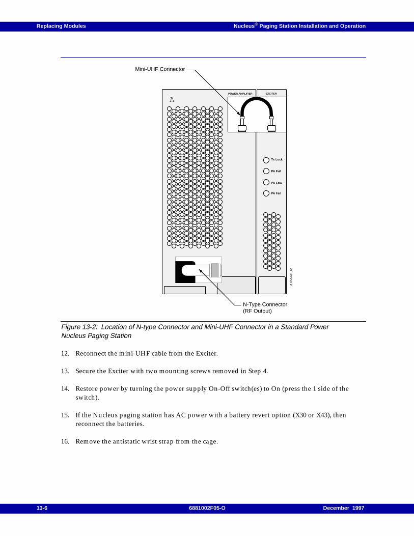
Replacing Modules Nucleus ® Paging Station Installation and Operation
Figure 13-2: Location of N-type Connector and Mini-UHF Connector in a Standard PowerNucleus Paging Station
12. Reconnect the mini-UHF cable from the Exciter.
13. Secure the Exciter with two mounting screws removed in Step 4.
14. Restore power by turning the power supply On-Off switch(es) to On (press the 1 side of theswitch).
15. If the Nucleus paging station has AC power with a battery revert option (X30 or X43), thenreconnect the batteries.
16. Remove the antistatic wrist strap from the cage.
POWER AMPLIFIER EXCITER
A
Tx Lock
PA Full
PA Low
PA Fail
2F05
SR
H-1
2
Mini-UHF Connector
N-Type Connector(RF Output)
13-6 6881002F05-O December 1997

Nucleus ® Paging Station Installation and Operation Replacing Modules
Post-replacement Optimization Procedure
Perform the alignment procedure (see Chapter 9, "SCM Station Alarms, Status, Troubleshooting, andAlignment"). If the Nucleus paging station has an External Circulator option (X676 or X677), calibratethe external Wattmeter.
December 1997 6881002F05-O 13-7
Replacing Modules Nucleus ® Paging Station Installation and Operation
Replacing the Power Amplifier (PA) in a Standard Power Station
This procedure replaces a PA in a high power Nucleus paging station and verifies the success of theprocedure.
Note: High power PAs are rated at 250 or 300 W.
Replacement Procedure
1. Connect an antistatic wrist strap connector to one of the two ground jacks on the cage.
2. If the Nucleus paging station has AC power with a battery revert option (X30 or X43), disconnectthe batteries.
3. Turn off power by turning the power supply On-Off switch(es) to Off (press the 0 side of theswitch).
4. Remove five mounting screws at the top of the PA.
5. Slide the PA partially out of the cage.
6. Disconnect the N-type connector (RF output from the Exciter) from the cutout in the lower leftcorner of the PA (see Figure 13-3).
7. Remove the faulty PA from cage.
8. Install a replacement PA by sliding the PA to within approximately 3 in. from full insertion.
9. Connect the RF output cable to the N-type connector at the cutout in the lower left corner of thePA.
10. Slide the PA in completely. Firmly press the connector into the backplane.
11. Secure the PA with mounting screws removed in Step 4.
12. Restore power by turning both On-Off switches to On (press the 1 side of the switch).
CAUTION
Do not force the PA into the backplane connectors and do not slam the PA against thebackplane. The PA has several connectors that must seat simultaneously. Do not push anyharder than necessary to seat the connectors.
13-8 6881002F05-O December 1997
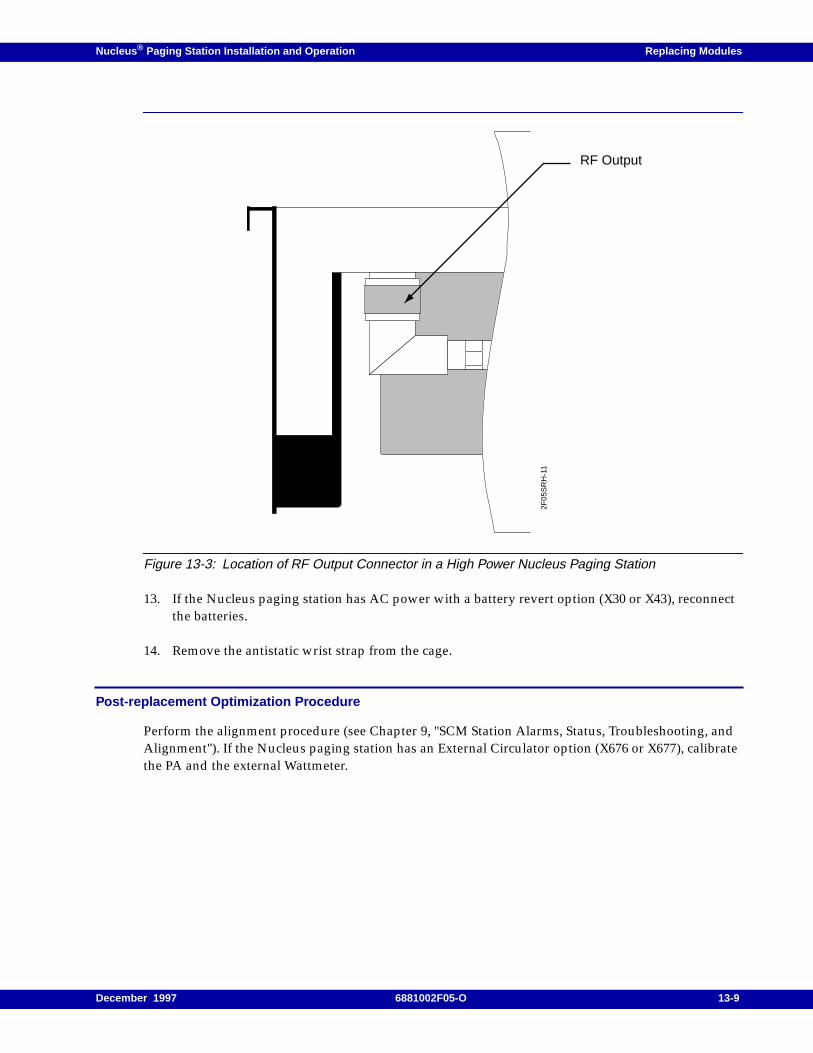
Nucleus ® Paging Station Installation and Operation Replacing Modules
Figure 13-3: Location of RF Output Connector in a High Power Nucleus Paging Station
13. If the Nucleus paging station has AC power with a battery revert option (X30 or X43), reconnectthe batteries.
14. Remove the antistatic wrist strap from the cage.
Post-replacement Optimization Procedure
Perform the alignment procedure (see Chapter 9, "SCM Station Alarms, Status, Troubleshooting, andAlignment"). If the Nucleus paging station has an External Circulator option (X676 or X677), calibratethe PA and the external Wattmeter.
2F05
SR
H-1
1
RF Output
December 1997 6881002F05-O 13-9

Replacing Modules Nucleus ® Paging Station Installation and Operation
Replacing the Power Supply
Use this procedure to replace a single power supply in a standard power Nucleus paging station orboth power supplies in a high power Nucleus paging station.
Note: The power supply located between the SCM and the Exciter on a high power station is power supplynumber 1. The power supply on the extreme left-hand side, to the left of the Exciter, is power supplynumber 2.
Replacement Procedure
1. Connect an antistatic wrist strap connector to one of the two ground jacks on the cage.
2. If the Nucleus paging station has AC power with a battery revert option (X30 or X43), disconnectthe batteries.
3. Turn off power by turning the power supply On-Off switch(es) to Off (press the 0 side of theswitch).
4. Remove the front-panel mounting screws from the very top and the very bottom of the powersupply front panel. These screws secure the power supply in the cage.
5. Remove the faulty power supply from the cage.
6. Remove the front cover from the faulty power supply.
7. Remove the front cover from the replacement power supply. Install the front cover from thefaulty power supply on the replacement power supply.
8. Install the replacement power supply by sliding it into the cage.
9. Seat the connector firmly in the backplane.
10. Secure power supply with two mounting screws removed in Step 4.
11. Restore power by turning the power supply On-Off switch(es) to On (press the 1 side of theswitch).
12. If the Nucleus paging station has AC power with a battery revert option (X30 or X43), reconnectthe batteries.
CAUTION
Do not slam the power supply against the backplane or push any harder than necessary toseat the connectors.
13-10 6881002F05-O December 1997

Nucleus ® Paging Station Installation and Operation Replacing Modules
Post-replacement Optimization Procedure
Perform one of the following alignment procedures (both described in Chapter 9, "SCM StationAlarms, Status, Troubleshooting, and Alignment"):
• Manual alignment
• Automatic alignment
December 1997 6881002F05-O 13-11
Replacing Modules Nucleus ® Paging Station Installation and Operation
Replacing the Station Control Board and Exciter as a Matched Pair
Note: This procedure also applies to the Nucleus Advanced Control (NAC) and matched Exciter.
Motorola aligns the Exciter and Station Control Board during manufacturing as a matched pair andassigns a common alignment ID number. If the replacement procedure does not replace them together,the system records an ALIGNMENT ID MISMATCHED alarm during start-up or reset.
Verify the alignment IDs from Status menu, SOFTWARE VERSIONS submenu, ALIGNMENT IDselection.
Note: The Station Control Board is part of the Station Control Module (SCM). The SCM front panel is alsopart of the SCM. The SCM front panel connects to the Station Control Board through a ribbonconnector.
Configuration Settings
The Station Control Board assigns a portion of memory to configuration parameters. This memorycontains default settings for customer-specific parameters such as channel frequency and outputpower. Before replacing the Station Control Board, record all non-default values from the currentconfiguration to facilitate reconfiguration after a installation.
Use Table B-1 to record Nucleus paging station configuration. Circle selections or write in values for allmenu and submenu items that are not default values.
Replacing the Exciter
1. Connect an antistatic wrist strap connector to one of the two ground jacks on the cage.
2. If the Nucleus paging station has AC power with a battery revert option (X30 or X43), disconnectthe batteries.
3. Turn off power by turning the power supply On-Off switch(es) to Off (press the 0 side of theswitch).
4. Remove the front-panel mounting screws from the very top and the very bottom of Exciter frontpanel. These screws secure the Exciter in the cage.
5. Disconnect the mini-UHF connector on RF cable that connects the PA to Exciter (see Figure 13-2).
Note: On a 300-W station, the mini-UHF connector passes through a slot in the front panel and connects tothe PA in the backplane. Remove the cable connector from the Exciter. Then slide the Exciter out,maintaining the cable in the track until the Exciter is clear of the station.
6. Remove the faulty Exciter from the cage.
13-12 6881002F05-O December 1997
Nucleus ® Paging Station Installation and Operation Replacing Modules
7. Install the replacement Exciter by sliding it into the cage. Seat the Exciter firmly in the backplane.
8. Reconnect the RF cable from the PA.
Note: On a standard power station, move the mini-UHF connector slightly to the right (slightly overreachingthe Exciter) to provide enough slack to connect the cable.
9. Secure the Exciter with the mounting screws removed in Step 4.
Replacing the Station Control Board
Use the following procedure to replace the Station Control Board:
Note: The station power supplies should still be turned off.
1. Connect an antistatic wrist strap connector to one of the two ground jacks on the cage.
2. Remove the mounting screws from the very top and very bottom of control front panel. Pull thecontrol front panel out until ribbon cable connector is accessible.
3. Disconnect the ribbon cable connector from the Station Control Board and set the control frontpanel aside.
4. Remove the faulty Station Control Board (on the left side in the cavity) from the cage.
5. Insert the board-pulling arm into the notch at the bottom front of the Station Control Board. Pullthe Station Control Board straight outward.
6. If the faulty Station Control Board has a Control-Receiver Interface Board (CRIB), remove theCRIB standoffs from the back of the faulty Station Control Board. Press the two tabs on eachstandoff together and pull the board off the standoff.
7. Remove the CRIB carefully from the faulty Station Control Board.
8. Insert the pins of the CRIB into connector P11 on the replacement Station Control Board. Alignthe pins properly. Seat the CRIB fully on the standoffs.
CAUTION
Do not slam the Exciter against the backplane or push any harder than necessary to seat theconnectors.
CAUTION
Do not slam the Station Control Board against the backplane or push any harder thannecessary to seat the connectors.
December 1997 6881002F05-O 13-13
Replacing Modules Nucleus ® Paging Station Installation and Operation
9. Slide the replacement Station Control Board in the cage. Press the connectors firmly into thebackplane.
10. Reconnect the ribbon cable from the rear of the SCM front panel to the connector on the StationControl Board.
11. Replace the SCM front panel and secure it with the mounting screws removed in Step 2.
12. Restore power by turning the power supply On-Off switch(es) to On (press the 1 side of theswitch).
13. If the Nucleus paging station has AC power with a battery revert option (X30 or X43), reconnectthe batteries.
14. Remove the antistatic wrist strap from the cage.
Post-replacement Optimization Procedure
Perform the following procedures to verify that the replacement procedure is successful, and toreconfigure the system, and to calibrate the transmitter.
1. Access the Station Alarms menu and verify that the system has not generated an ALIGNMENT IDMISMATCHED alarm.
2. Configure the Nucleus paging station (see Chapter 8, "SCM Station Configuration"). Use theconfiguration settings recorded in Appendix B to restore the Nucleus paging station to itsprevious configuration.
3. Perform Nucleus paging station alignment (see Chapter 9, "SCM Station Alarms, Status,Troubleshooting, and Alignment").
4. Verify transmitter circuitry and reference oscillator performance (see Chapter 12, "NAC AlarmConfiguration and Verification").
13-14 6881002F05-O December 1997
Nucleus ® Paging Station Installation and Operation Replacing Modules
Backplane
This section describes the replacement procedure and post-replacement checkout for the Nucleusbackplane.
Replacement Procedure
1. Connect an antistatic wrist strap connector to one of the two ground jacks on the cage.
2. If the Nucleus paging station has AC power with a battery revert option (X30 or X43), disconnectthe batteries.
3. Turn off power by turning the power supply On-Off switch(es) to Off (press the 0 side of theswitch).
4. Remove all modules and boards from the cage. Place all modules and boards in antistatic bags oron properly grounded antistatic surfaces.
5. Label all cables connected to the rear of the backplane. Disconnect all cables from the backplane.
6. Remove the 11 TORX head screws securing the rear metal shield and backplane to the cage.
7. Remove the metal shield and the backplane.
8. Slide the two guide pins located at each end on the bottom of the metal shield from thebackplane.
9. Remove the backplane from the cage.
10. Install the replacement backplane and rear metal shield. Insert and tighten the 11 TORX headscrews removed in Step 6.
11. Reconnect all cables to the rear of the backplane (see Step 5)
12. Reinstall all modules and boards removed in Step 4.
13. Restore power by turning the power supply On-Off switch(es) to On (press the 1 side of theswitch).
14. If the Nucleus paging station has AC power with a battery revert option (X30 or X43), reconnectthe batteries.
Post-replacement Optimization Procedure
This procedure requires no post-replacement optimization.
December 1997 6881002F05-O 13-15

Replacing Modules Nucleus ® Paging Station Installation and Operation
13-16 6881002F05-O December 1997
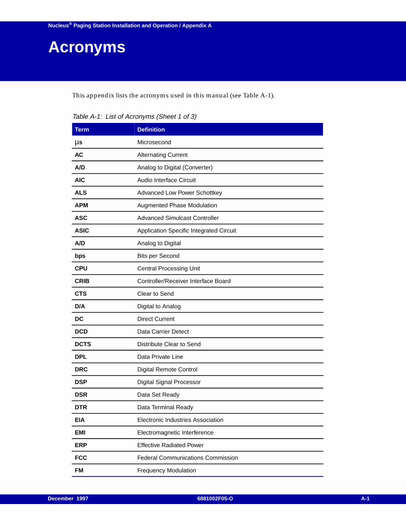
Nucleus ® Paging Station Installation and Operation / Appendix A
Acronyms A
This appendix lists the acronyms used in this manual (see Table A-1).
Table A-1: List of Acronyms (Sheet 1 of 3)
Term Definition
µs Microsecond
AC Alternating Current
A/D Analog to Digital (Converter)
AIC Audio Interface Circuit
ALS Advanced Low Power Schottkey
APM Augmented Phase Modulation
ASC Advanced Simulcast Controller
ASIC Application Specific Integrated Circuit
A/D Analog to Digital
bps Bits per Second
CPU Central Processing Unit
CRIB Controller/Receiver Interface Board
CTS Clear to Send
D/A Digital to Analog
DC Direct Current
DCD Data Carrier Detect
DCTS Distribute Clear to Send
DPL Data Private Line
DRC Digital Remote Control
DSP Digital Signal Processor
DSR Data Set Ready
DTR Data Terminal Ready
EIA Electronic Industries Association
EMI Electromagnetic Interference
ERP Effective Radiated Power
FCC Federal Communications Commission
FM Frequency Modulation
December 1997 6881002F05-O A-1
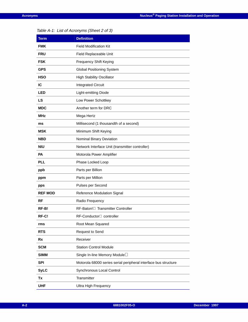
Acronyms Nucleus ® Paging Station Installation and Operation
FMK Field Modification Kit
FRU Field Replaceable Unit
FSK Frequency Shift Keying
GPS Global Positioning System
HSO High Stability Oscillator
IC Integrated Circuit
LED Light-emitting Diode
LS Low Power Schottkey
MDC Another term for DRC
MHz Mega Hertz
ms Millisecond (1 thousandth of a second)
MSK Minimum Shift Keying
NBD Nominal Binary Deviation
NIU Network Interface Unit (transmitter controller)
PA Motorola Power Amplifier
PLL Phase Locked Loop
ppb Parts per Billion
ppm Parts per Million
pps Pulses per Second
REF MOD Reference Modulation Signal
RF Radio Frequency
RF-B! RF-Baton! Transmitter Controller
RF-C! RF-Conductor controller
rms Root Mean Squared
RTS Request to Send
Rx Receiver
SCM Station Control Module
SIMM Single In-line Memory Module
SPI Motorola 68000 series serial peripheral interface bus structure
SyLC Synchronous Local Control
Tx Transmitter
UHF Ultra High Frequency
Table A-1: List of Acronyms (Sheet 2 of 3)
Term Definition
A-2 6881002F05-O December 1997
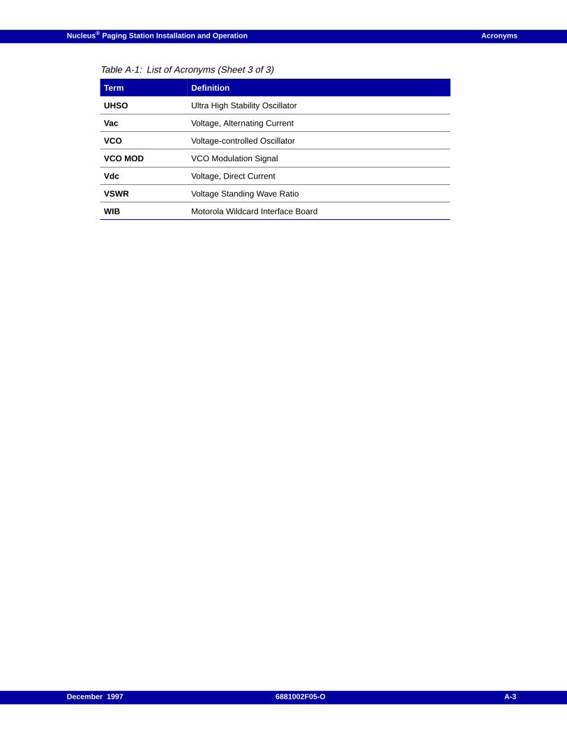
Nucleus ® Paging Station Installation and Operation Acronyms
UHSO Ultra High Stability Oscillator
Vac Voltage, Alternating Current
VCO Voltage-controlled Oscillator
VCO MOD VCO Modulation Signal
Vdc Voltage, Direct Current
VSWR Voltage Standing Wave Ratio
WIB Motorola Wildcard Interface Board
Table A-1: List of Acronyms (Sheet 3 of 3)
Term Definition
December 1997 6881002F05-O A-3

Acronyms Nucleus ® Paging Station Installation and Operation
A-4 6881002F05-O December 1997
Nucleus ® Paging Station Installation and Operation / Appendix B
Configuration Record B
This appendix contains the installation and configuration record for the Nucleus paging stationinstalled at a single site. The contents of this appendix include:
Use in Initial Configuration, B-2
Use in Module Replacement, B-3
December 1997 6881002F05-O B-1

Configuration Record Nucleus ® Paging Station Installation and Operation
Use in Initial Configuration
When you install and configure the Nucleus Paging Station, use Table B-1 to record the completeconfiguration of the station. Record all settings in the right hand column of the table or circle theappropriate setting if it is already listed there. For values that are read only, record them for futurereference (to guard against system drift).
B-2 6881002F05-O December 1997
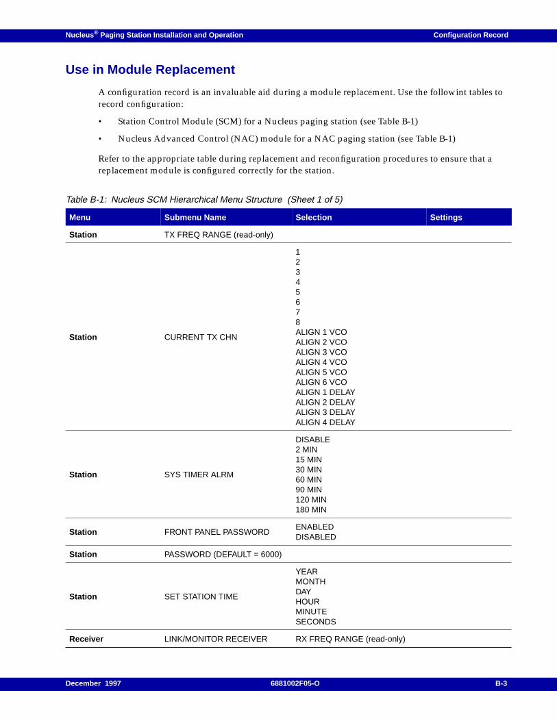
Nucleus ® Paging Station Installation and Operation Configuration Record
Use in Module Replacement
A configuration record is an invaluable aid during a module replacement. Use the followint tables torecord configuration:
• Station Control Module (SCM) for a Nucleus paging station (see Table B-1)
• Nucleus Advanced Control (NAC) module for a NAC paging station (see Table B-1)
Refer to the appropriate table during replacement and reconfiguration procedures to ensure that areplacement module is configured correctly for the station.
Table B-1: Nucleus SCM Hierarchical Menu Structure (Sheet 1 of 5)
Menu Submenu Name Selection Settings
Station TX FREQ RANGE (read-only)
Station CURRENT TX CHN
12345678ALIGN 1 VCOALIGN 2 VCOALIGN 3 VCOALIGN 4 VCOALIGN 5 VCOALIGN 6 VCOALIGN 1 DELAYALIGN 2 DELAYALIGN 3 DELAYALIGN 4 DELAY
Station SYS TIMER ALRM
DISABLE2 MIN15 MIN30 MIN60 MIN90 MIN120 MIN180 MIN
Station FRONT PANEL PASSWORDENABLEDDISABLED
Station PASSWORD (DEFAULT = 6000)
Station SET STATION TIME
YEARMONTHDAYHOURMINUTESECONDS
Receiver LINK/MONITOR RECEIVER RX FREQ RANGE (read-only)
December 1997 6881002F05-O B-3
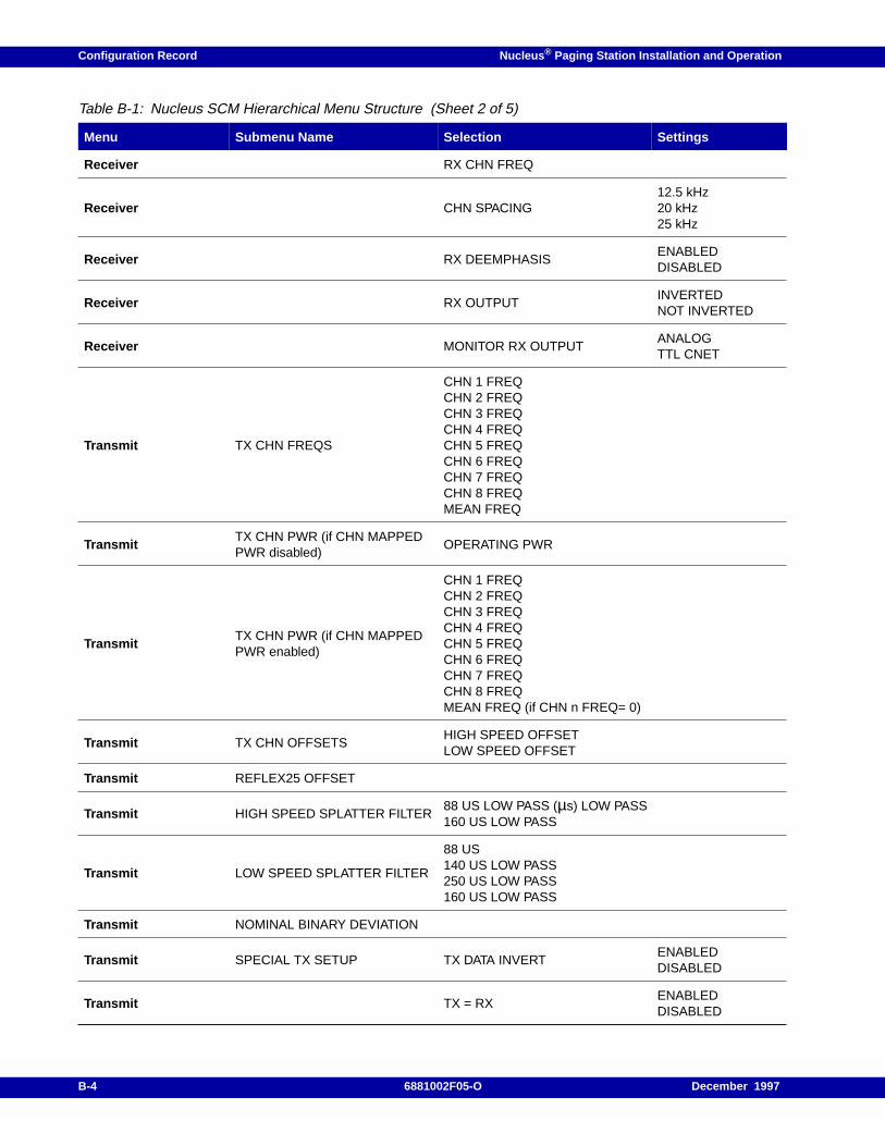
Configuration Record Nucleus ® Paging Station Installation and Operation
Receiver RX CHN FREQ
Receiver CHN SPACING12.5 kHz20 kHz25 kHz
Receiver RX DEEMPHASISENABLEDDISABLED
Receiver RX OUTPUTINVERTEDNOT INVERTED
Receiver MONITOR RX OUTPUTANALOGTTL CNET
Transmit TX CHN FREQS
CHN 1 FREQCHN 2 FREQCHN 3 FREQCHN 4 FREQCHN 5 FREQCHN 6 FREQCHN 7 FREQCHN 8 FREQMEAN FREQ
TransmitTX CHN PWR (if CHN MAPPEDPWR disabled)
OPERATING PWR
TransmitTX CHN PWR (if CHN MAPPEDPWR enabled)
CHN 1 FREQCHN 2 FREQCHN 3 FREQCHN 4 FREQCHN 5 FREQCHN 6 FREQCHN 7 FREQCHN 8 FREQMEAN FREQ (if CHN n FREQ= 0)
Transmit TX CHN OFFSETSHIGH SPEED OFFSETLOW SPEED OFFSET
Transmit REFLEX25 OFFSET
Transmit HIGH SPEED SPLATTER FILTER88 US LOW PASS (µs) LOW PASS160 US LOW PASS
Transmit LOW SPEED SPLATTER FILTER
88 US140 US LOW PASS250 US LOW PASS160 US LOW PASS
Transmit NOMINAL BINARY DEVIATION
Transmit SPECIAL TX SETUP TX DATA INVERTENABLEDDISABLED
Transmit TX = RXENABLEDDISABLED
Table B-1: Nucleus SCM Hierarchical Menu Structure (Sheet 2 of 5)
Menu Submenu Name Selection Settings
B-4 6881002F05-O December 1997
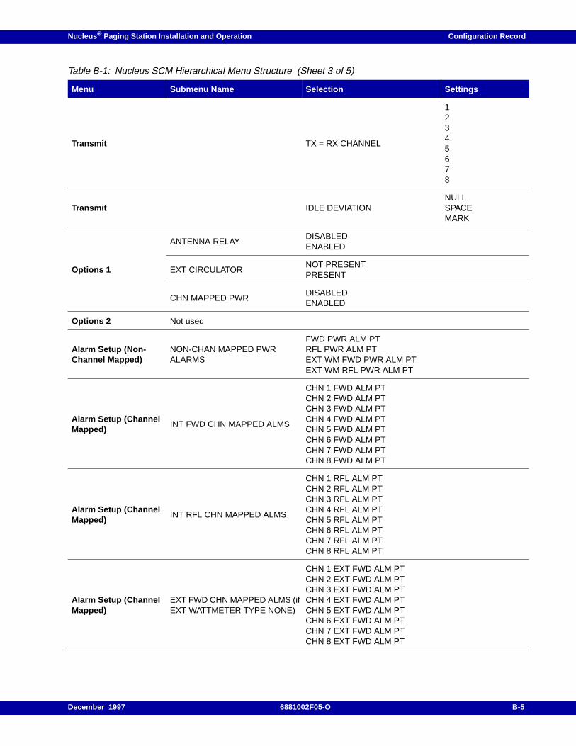
Nucleus ® Paging Station Installation and Operation Configuration Record
Transmit TX = RX CHANNEL
12345678
Transmit IDLE DEVIATIONNULLSPACEMARK
Options 1
ANTENNA RELAYDISABLEDENABLED
EXT CIRCULATORNOT PRESENTPRESENT
CHN MAPPED PWRDISABLEDENABLED
Options 2 Not used
Alarm Setup (Non-Channel Mapped)
NON-CHAN MAPPED PWRALARMS
FWD PWR ALM PTRFL PWR ALM PTEXT WM FWD PWR ALM PTEXT WM RFL PWR ALM PT
Alarm Setup (ChannelMapped)
INT FWD CHN MAPPED ALMS
CHN 1 FWD ALM PTCHN 2 FWD ALM PTCHN 3 FWD ALM PTCHN 4 FWD ALM PTCHN 5 FWD ALM PTCHN 6 FWD ALM PTCHN 7 FWD ALM PTCHN 8 FWD ALM PT
Alarm Setup (ChannelMapped)
INT RFL CHN MAPPED ALMS
CHN 1 RFL ALM PTCHN 2 RFL ALM PTCHN 3 RFL ALM PTCHN 4 RFL ALM PTCHN 5 RFL ALM PTCHN 6 RFL ALM PTCHN 7 RFL ALM PTCHN 8 RFL ALM PT
Alarm Setup (ChannelMapped)
EXT FWD CHN MAPPED ALMS (ifEXT WATTMETER TYPE NONE)
CHN 1 EXT FWD ALM PTCHN 2 EXT FWD ALM PTCHN 3 EXT FWD ALM PTCHN 4 EXT FWD ALM PTCHN 5 EXT FWD ALM PTCHN 6 EXT FWD ALM PTCHN 7 EXT FWD ALM PTCHN 8 EXT FWD ALM PT
Table B-1: Nucleus SCM Hierarchical Menu Structure (Sheet 3 of 5)
Menu Submenu Name Selection Settings
December 1997 6881002F05-O B-5
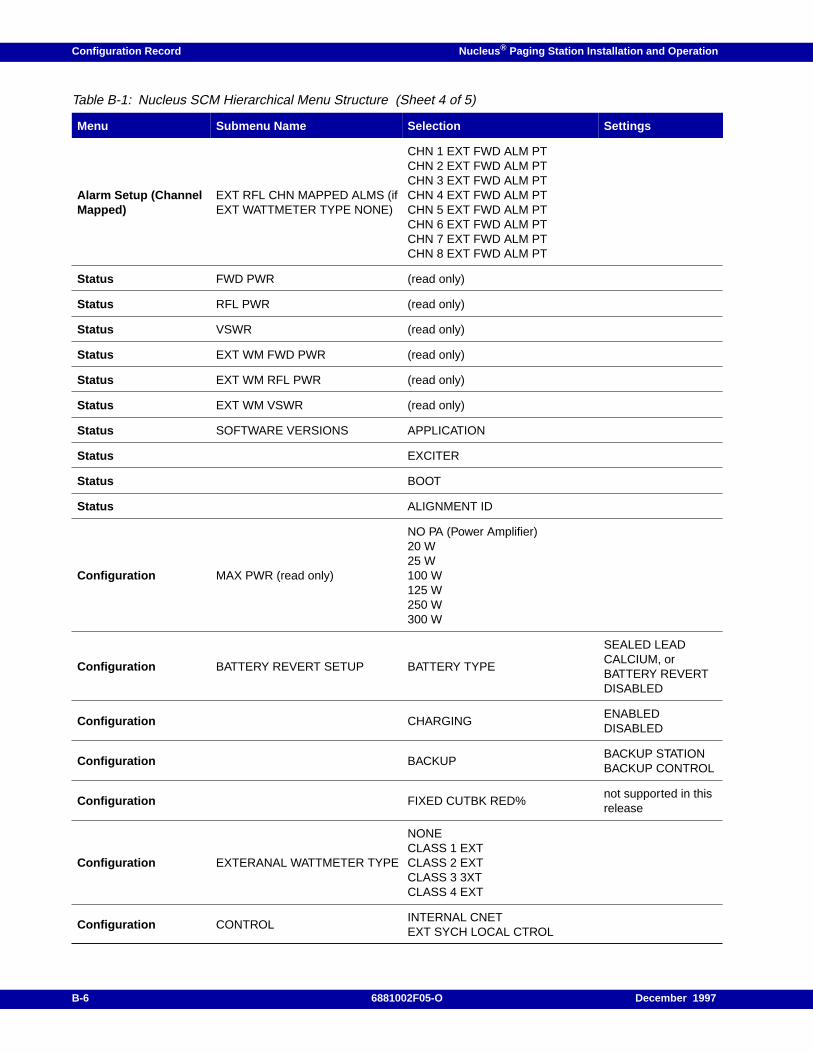
Configuration Record Nucleus ® Paging Station Installation and Operation
Alarm Setup (ChannelMapped)
EXT RFL CHN MAPPED ALMS (ifEXT WATTMETER TYPE NONE)
CHN 1 EXT FWD ALM PTCHN 2 EXT FWD ALM PTCHN 3 EXT FWD ALM PTCHN 4 EXT FWD ALM PTCHN 5 EXT FWD ALM PTCHN 6 EXT FWD ALM PTCHN 7 EXT FWD ALM PTCHN 8 EXT FWD ALM PT
Status FWD PWR (read only)
Status RFL PWR (read only)
Status VSWR (read only)
Status EXT WM FWD PWR (read only)
Status EXT WM RFL PWR (read only)
Status EXT WM VSWR (read only)
Status SOFTWARE VERSIONS APPLICATION
Status EXCITER
Status BOOT
Status ALIGNMENT ID
Configuration MAX PWR (read only)
NO PA (Power Amplifier)20 W25 W100 W125 W250 W300 W
Configuration BATTERY REVERT SETUP BATTERY TYPE
SEALED LEADCALCIUM, orBATTERY REVERTDISABLED
Configuration CHARGINGENABLEDDISABLED
Configuration BACKUPBACKUP STATIONBACKUP CONTROL
Configuration FIXED CUTBK RED%not supported in thisrelease
Configuration EXTERANAL WATTMETER TYPE
NONECLASS 1 EXTCLASS 2 EXTCLASS 3 3XTCLASS 4 EXT
Configuration CONTROLINTERNAL CNETEXT SYCH LOCAL CTROL
Table B-1: Nucleus SCM Hierarchical Menu Structure (Sheet 4 of 5)
Menu Submenu Name Selection Settings
B-6 6881002F05-O December 1997
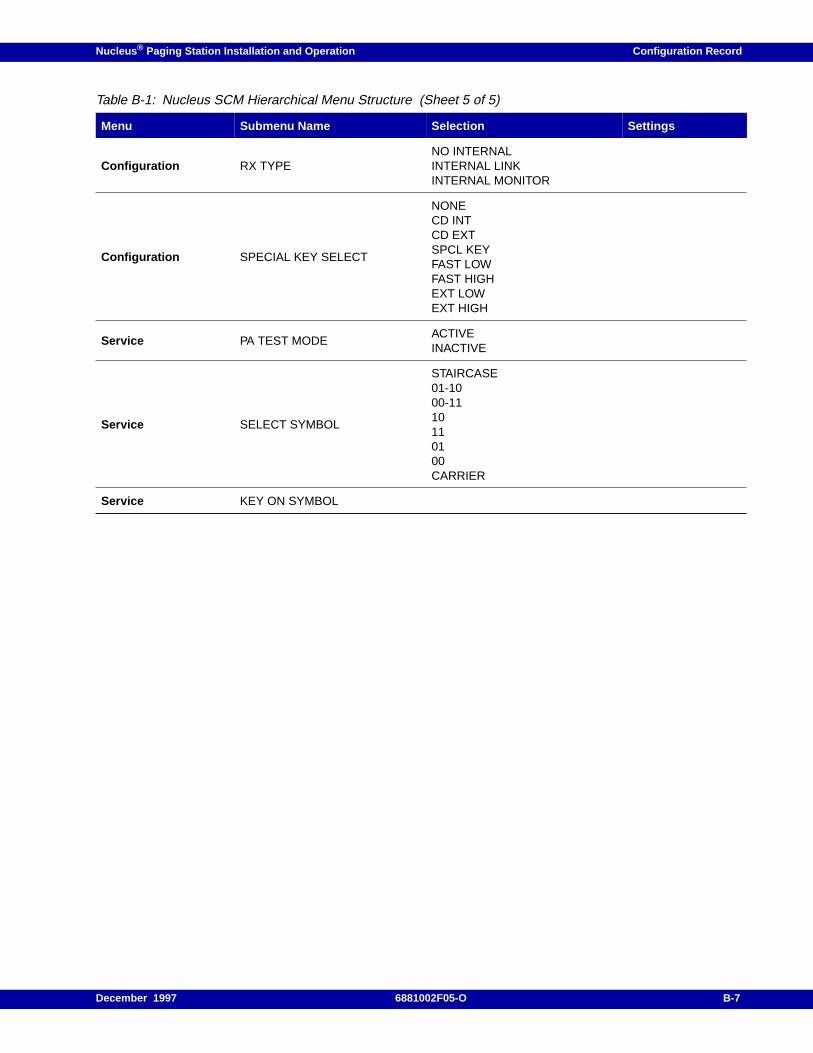
Nucleus ® Paging Station Installation and Operation Configuration Record
Configuration RX TYPENO INTERNALINTERNAL LINKINTERNAL MONITOR
Configuration SPECIAL KEY SELECT
NONECD INTCD EXTSPCL KEYFAST LOWFAST HIGHEXT LOWEXT HIGH
Service PA TEST MODEACTIVEINACTIVE
Service SELECT SYMBOL
STAIRCASE01-1000-1110110100CARRIER
Service KEY ON SYMBOL
Table B-1: Nucleus SCM Hierarchical Menu Structure (Sheet 5 of 5)
Menu Submenu Name Selection Settings
December 1997 6881002F05-O B-7
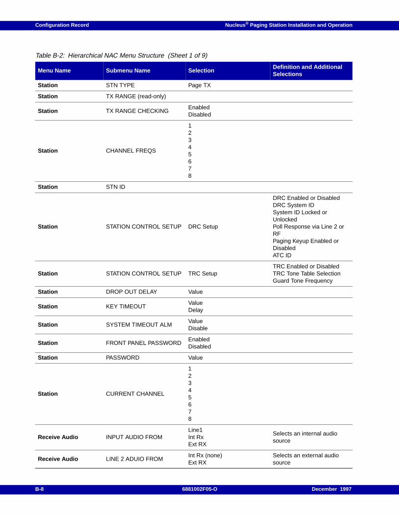
Configuration Record Nucleus ® Paging Station Installation and Operation
Table B-2: Hierarchical NAC Menu Structure (Sheet 1 of 9)
Menu Name Submenu Name SelectionDefinition and AdditionalSelections
Station STN TYPE Page TX
Station TX RANGE (read-only)
Station TX RANGE CHECKINGEnabledDisabled
Station CHANNEL FREQS
12345678
Station STN ID
Station STATION CONTROL SETUP DRC Setup
DRC Enabled or DisabledDRC System IDSystem ID Locked orUnlockedPoll Response via Line 2 orRFPaging Keyup Enabled orDisabledATC ID
Station STATION CONTROL SETUP TRC SetupTRC Enabled or DisabledTRC Tone Table SelectionGuard Tone Frequency
Station DROP OUT DELAY Value
Station KEY TIMEOUTValueDelay
Station SYSTEM TIMEOUT ALMValueDisable
Station FRONT PANEL PASSWORDEnabledDisabled
Station PASSWORD Value
Station CURRENT CHANNEL
12345678
Receive Audio INPUT AUDIO FROMLine1Int RxExt RX
Selects an internal audiosource
Receive Audio LINE 2 ADUIO FROMInt Rx (none)Ext RX
Selects an external audiosource
B-8 6881002F05-O December 1997
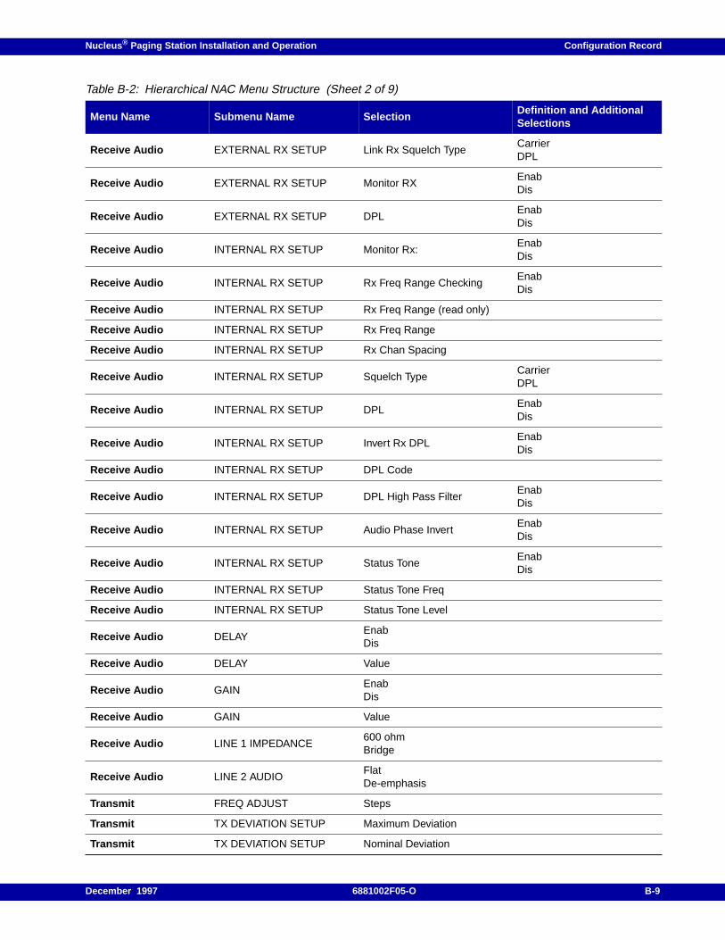
Nucleus ® Paging Station Installation and Operation Configuration Record
Receive Audio EXTERNAL RX SETUP Link Rx Squelch TypeCarrierDPL
Receive Audio EXTERNAL RX SETUP Monitor RXEnabDis
Receive Audio EXTERNAL RX SETUP DPLEnabDis
Receive Audio INTERNAL RX SETUP Monitor Rx:EnabDis
Receive Audio INTERNAL RX SETUP Rx Freq Range CheckingEnabDis
Receive Audio INTERNAL RX SETUP Rx Freq Range (read only)
Receive Audio INTERNAL RX SETUP Rx Freq Range
Receive Audio INTERNAL RX SETUP Rx Chan Spacing
Receive Audio INTERNAL RX SETUP Squelch TypeCarrierDPL
Receive Audio INTERNAL RX SETUP DPLEnabDis
Receive Audio INTERNAL RX SETUP Invert Rx DPLEnabDis
Receive Audio INTERNAL RX SETUP DPL Code
Receive Audio INTERNAL RX SETUP DPL High Pass FilterEnabDis
Receive Audio INTERNAL RX SETUP Audio Phase InvertEnabDis
Receive Audio INTERNAL RX SETUP Status ToneEnabDis
Receive Audio INTERNAL RX SETUP Status Tone Freq
Receive Audio INTERNAL RX SETUP Status Tone Level
Receive Audio DELAYEnabDis
Receive Audio DELAY Value
Receive Audio GAINEnabDis
Receive Audio GAIN Value
Receive Audio LINE 1 IMPEDANCE600 ohmBridge
Receive Audio LINE 2 AUDIOFlatDe-emphasis
Transmit FREQ ADJUST Steps
Transmit TX DEVIATION SETUP Maximum Deviation
Transmit TX DEVIATION SETUP Nominal Deviation
Table B-2: Hierarchical NAC Menu Structure (Sheet 2 of 9)
Menu Name Submenu Name SelectionDefinition and AdditionalSelections
December 1997 6881002F05-O B-9
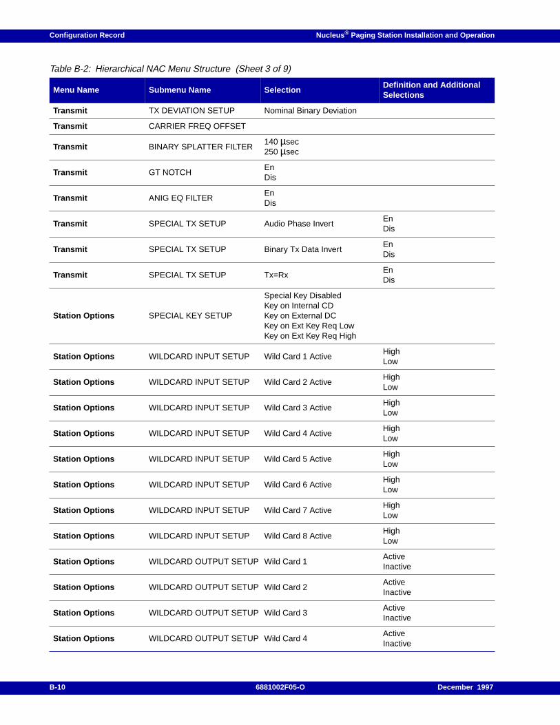
Configuration Record Nucleus ® Paging Station Installation and Operation
Transmit TX DEVIATION SETUP Nominal Binary Deviation
Transmit CARRIER FREQ OFFSET
Transmit BINARY SPLATTER FILTER140 µsec250 µsec
Transmit GT NOTCHEnDis
Transmit ANIG EQ FILTEREnDis
Transmit SPECIAL TX SETUP Audio Phase InvertEnDis
Transmit SPECIAL TX SETUP Binary Tx Data InvertEnDis
Transmit SPECIAL TX SETUP Tx=RxEnDis
Station Options SPECIAL KEY SETUP
Special Key DisabledKey on Internal CDKey on External DCKey on Ext Key Req LowKey on Ext Key Req High
Station Options WILDCARD INPUT SETUP Wild Card 1 ActiveHighLow
Station Options WILDCARD INPUT SETUP Wild Card 2 ActiveHighLow
Station Options WILDCARD INPUT SETUP Wild Card 3 ActiveHighLow
Station Options WILDCARD INPUT SETUP Wild Card 4 ActiveHighLow
Station Options WILDCARD INPUT SETUP Wild Card 5 ActiveHighLow
Station Options WILDCARD INPUT SETUP Wild Card 6 ActiveHighLow
Station Options WILDCARD INPUT SETUP Wild Card 7 ActiveHighLow
Station Options WILDCARD INPUT SETUP Wild Card 8 ActiveHighLow
Station Options WILDCARD OUTPUT SETUP Wild Card 1ActiveInactive
Station Options WILDCARD OUTPUT SETUP Wild Card 2ActiveInactive
Station Options WILDCARD OUTPUT SETUP Wild Card 3ActiveInactive
Station Options WILDCARD OUTPUT SETUP Wild Card 4ActiveInactive
Table B-2: Hierarchical NAC Menu Structure (Sheet 3 of 9)
Menu Name Submenu Name SelectionDefinition and AdditionalSelections
B-10 6881002F05-O December 1997
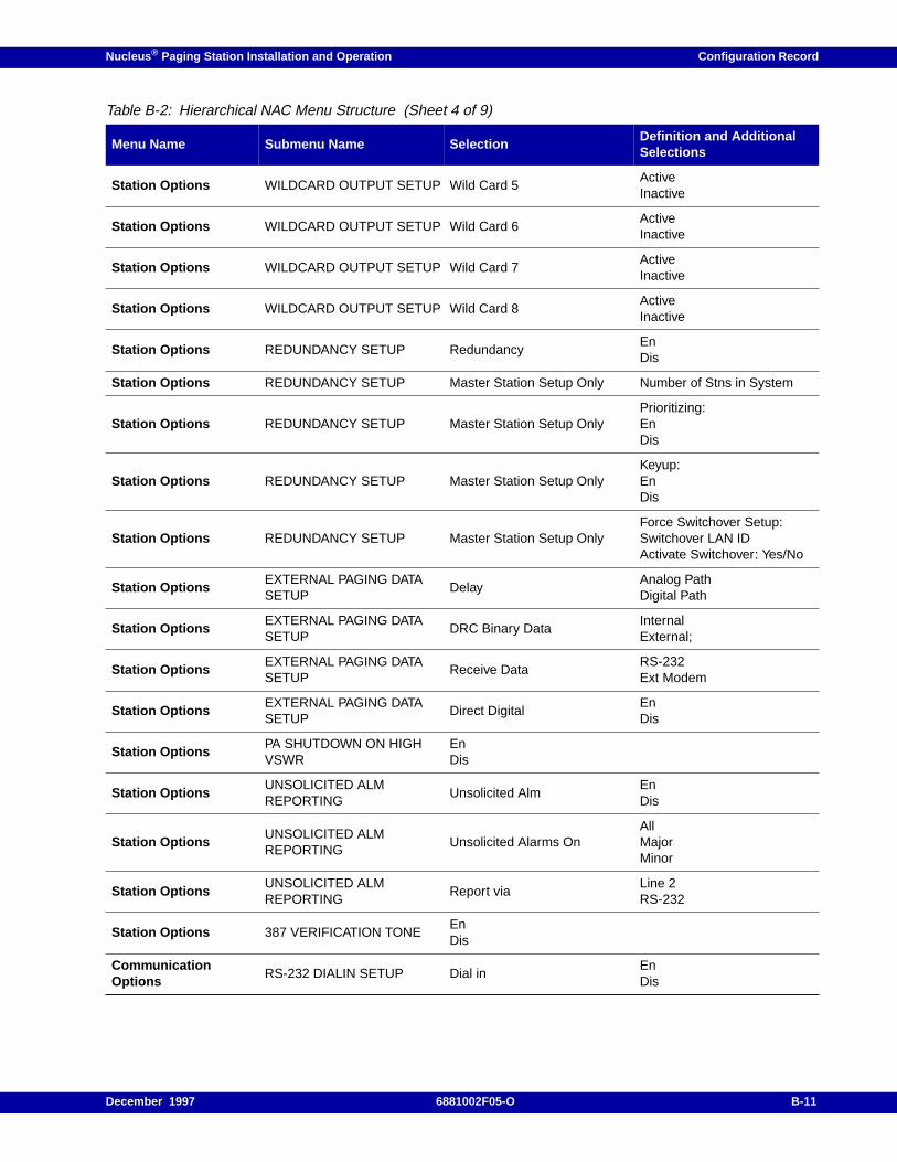
Nucleus ® Paging Station Installation and Operation Configuration Record
Station Options WILDCARD OUTPUT SETUP Wild Card 5ActiveInactive
Station Options WILDCARD OUTPUT SETUP Wild Card 6ActiveInactive
Station Options WILDCARD OUTPUT SETUP Wild Card 7ActiveInactive
Station Options WILDCARD OUTPUT SETUP Wild Card 8ActiveInactive
Station Options REDUNDANCY SETUP RedundancyEnDis
Station Options REDUNDANCY SETUP Master Station Setup Only Number of Stns in System
Station Options REDUNDANCY SETUP Master Station Setup OnlyPrioritizing:EnDis
Station Options REDUNDANCY SETUP Master Station Setup OnlyKeyup:EnDis
Station Options REDUNDANCY SETUP Master Station Setup OnlyForce Switchover Setup:Switchover LAN IDActivate Switchover: Yes/No
Station OptionsEXTERNAL PAGING DATASETUP
DelayAnalog PathDigital Path
Station OptionsEXTERNAL PAGING DATASETUP
DRC Binary DataInternalExternal;
Station OptionsEXTERNAL PAGING DATASETUP
Receive DataRS-232Ext Modem
Station OptionsEXTERNAL PAGING DATASETUP
Direct DigitalEnDis
Station OptionsPA SHUTDOWN ON HIGHVSWR
EnDis
Station OptionsUNSOLICITED ALMREPORTING
Unsolicited AlmEnDis
Station OptionsUNSOLICITED ALMREPORTING
Unsolicited Alarms OnAllMajorMinor
Station OptionsUNSOLICITED ALMREPORTING
Report viaLine 2RS-232
Station Options 387 VERIFICATION TONEEnDis
CommunicationOptions
RS-232 DIALIN SETUP Dial inEnDis
Table B-2: Hierarchical NAC Menu Structure (Sheet 4 of 9)
Menu Name Submenu Name SelectionDefinition and AdditionalSelections
December 1997 6881002F05-O B-11
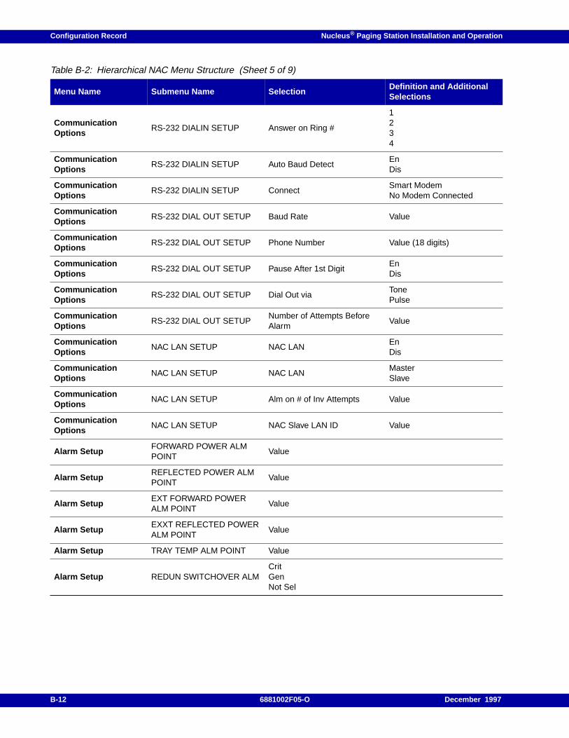
Configuration Record Nucleus ® Paging Station Installation and Operation
CommunicationOptions
RS-232 DIALIN SETUP Answer on Ring #
1234
CommunicationOptions
RS-232 DIALIN SETUP Auto Baud DetectEnDis
CommunicationOptions
RS-232 DIALIN SETUP ConnectSmart ModemNo Modem Connected
CommunicationOptions
RS-232 DIAL OUT SETUP Baud Rate Value
CommunicationOptions
RS-232 DIAL OUT SETUP Phone Number Value (18 digits)
CommunicationOptions
RS-232 DIAL OUT SETUP Pause After 1st DigitEnDis
CommunicationOptions
RS-232 DIAL OUT SETUP Dial Out viaTonePulse
CommunicationOptions
RS-232 DIAL OUT SETUPNumber of Attempts BeforeAlarm
Value
CommunicationOptions
NAC LAN SETUP NAC LANEnDis
CommunicationOptions
NAC LAN SETUP NAC LANMasterSlave
CommunicationOptions
NAC LAN SETUP Alm on # of Inv Attempts Value
CommunicationOptions
NAC LAN SETUP NAC Slave LAN ID Value
Alarm SetupFORWARD POWER ALMPOINT
Value
Alarm SetupREFLECTED POWER ALMPOINT
Value
Alarm SetupEXT FORWARD POWERALM POINT
Value
Alarm SetupEXXT REFLECTED POWERALM POINT
Value
Alarm Setup TRAY TEMP ALM POINT Value
Alarm Setup REDUN SWITCHOVER ALMCritGenNot Sel
Table B-2: Hierarchical NAC Menu Structure (Sheet 5 of 9)
Menu Name Submenu Name SelectionDefinition and AdditionalSelections
B-12 6881002F05-O December 1997
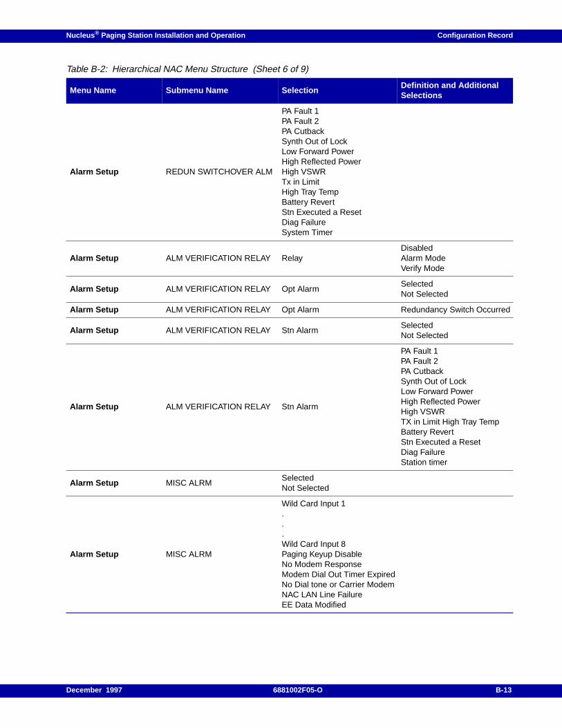
Nucleus ® Paging Station Installation and Operation Configuration Record
Alarm Setup REDUN SWITCHOVER ALM
PA Fault 1PA Fault 2PA CutbackSynth Out of LockLow Forward PowerHigh Reflected PowerHigh VSWRTx in LimitHigh Tray TempBattery RevertStn Executed a ResetDiag FailureSystem Timer
Alarm Setup ALM VERIFICATION RELAY RelayDisabledAlarm ModeVerify Mode
Alarm Setup ALM VERIFICATION RELAY Opt AlarmSelectedNot Selected
Alarm Setup ALM VERIFICATION RELAY Opt Alarm Redundancy Switch Occurred
Alarm Setup ALM VERIFICATION RELAY Stn AlarmSelectedNot Selected
Alarm Setup ALM VERIFICATION RELAY Stn Alarm
PA Fault 1PA Fault 2PA CutbackSynth Out of LockLow Forward PowerHigh Reflected PowerHigh VSWRTX in Limit High Tray TempBattery RevertStn Executed a ResetDiag FailureStation timer
Alarm Setup MISC ALRMSelectedNot Selected
Alarm Setup MISC ALRM
Wild Card Input 1...Wild Card Input 8Paging Keyup DisableNo Modem ResponseModem Dial Out Timer ExpiredNo Dial tone or Carrier ModemNAC LAN Line FailureEE Data Modified
Table B-2: Hierarchical NAC Menu Structure (Sheet 6 of 9)
Menu Name Submenu Name SelectionDefinition and AdditionalSelections
December 1997 6881002F05-O B-13
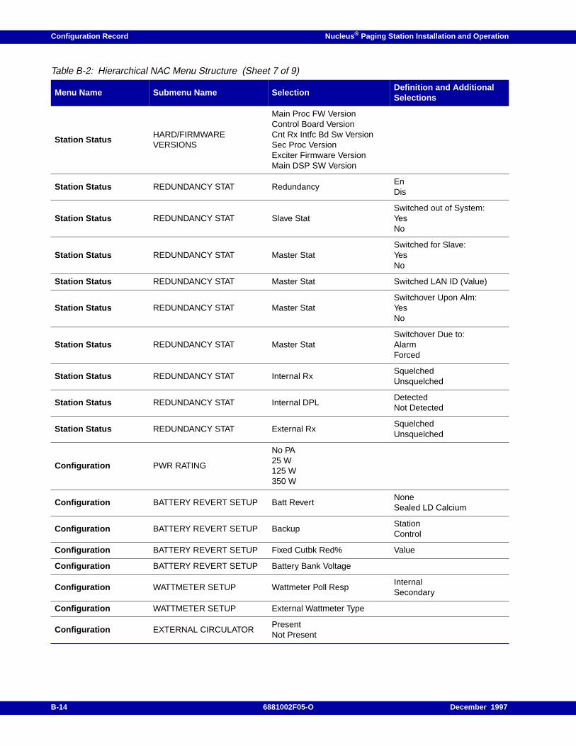
Configuration Record Nucleus ® Paging Station Installation and Operation
Station StatusHARD/FIRMWAREVERSIONS
Main Proc FW VersionControl Board VersionCnt Rx Intfc Bd Sw VersionSec Proc VersionExciter Firmware VersionMain DSP SW Version
Station Status REDUNDANCY STAT RedundancyEnDis
Station Status REDUNDANCY STAT Slave StatSwitched out of System:YesNo
Station Status REDUNDANCY STAT Master StatSwitched for Slave:YesNo
Station Status REDUNDANCY STAT Master Stat Switched LAN ID (Value)
Station Status REDUNDANCY STAT Master StatSwitchover Upon Alm:YesNo
Station Status REDUNDANCY STAT Master StatSwitchover Due to:AlarmForced
Station Status REDUNDANCY STAT Internal RxSquelchedUnsquelched
Station Status REDUNDANCY STAT Internal DPLDetectedNot Detected
Station Status REDUNDANCY STAT External RxSquelchedUnsquelched
Configuration PWR RATING
No PA25 W125 W350 W
Configuration BATTERY REVERT SETUP Batt RevertNoneSealed LD Calcium
Configuration BATTERY REVERT SETUP BackupStationControl
Configuration BATTERY REVERT SETUP Fixed Cutbk Red% Value
Configuration BATTERY REVERT SETUP Battery Bank Voltage
Configuration WATTMETER SETUP Wattmeter Poll RespInternalSecondary
Configuration WATTMETER SETUP External Wattmeter Type
Configuration EXTERNAL CIRCULATORPresentNot Present
Table B-2: Hierarchical NAC Menu Structure (Sheet 7 of 9)
Menu Name Submenu Name SelectionDefinition and AdditionalSelections
B-14 6881002F05-O December 1997
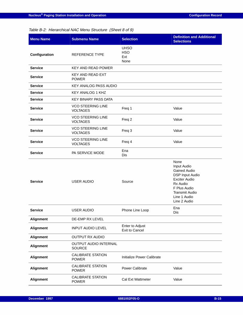
Nucleus ® Paging Station Installation and Operation Configuration Record
Configuration REFERENCE TYPE
UHSOHSOExtNone
Service KEY AND READ POWER
ServiceKEY AND READ EXTPOWER
Service KEY ANALOG PASS AUDIO
Service KEY ANALOG 1 KHZ
Service KEY BINARY PASS DATA
ServiceVCO STEERING LINEVOLTAGES
Freq 1 Value
ServiceVCO STEERING LINEVOLTAGES
Freq 2 Value
ServiceVCO STEERING LINEVOLTAGES
Freq 3 Value
ServiceVCO STEERING LINEVOLTAGES
Freq 4 Value
Service PA SERVICE MODEEnaDis
Service USER AUDIO Source
NoneInput AudioGained AudioDSP Input AudioExciter AudioRx AudioF Plus AudioTransmit AudioLine 1 AudioLine 2 Audio
Service USER AUDIO Phone Line LoopEnaDis
Alignment DE-EMP RX LEVEL
Alignment INPUT AUDIO LEVELEnter to AdjustExit to Cancel
Alignment OUTPUT RX AUDIO
AlignmentOUTPUT AUDIO INTERNALSOURCE
AlignmentCALIBRATE STATIONPOWER
Initialize Power Calibrate
AlignmentCALIBRATE STATIONPOWER
Power Calibrate Value
AlignmentCALIBRATE STATIONPOWER
Cal Ext Wattmeter Value
Table B-2: Hierarchical NAC Menu Structure (Sheet 8 of 9)
Menu Name Submenu Name SelectionDefinition and AdditionalSelections
December 1997 6881002F05-O B-15
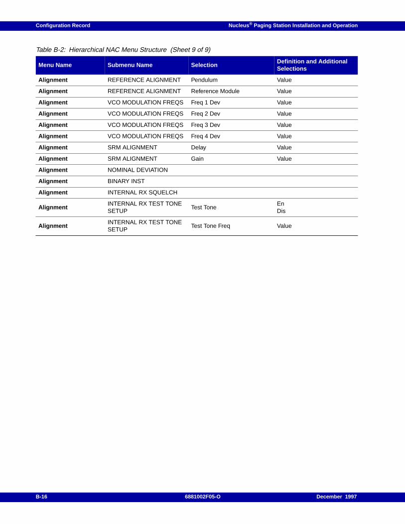
Configuration Record Nucleus ® Paging Station Installation and Operation
Alignment REFERENCE ALIGNMENT Pendulum Value
Alignment REFERENCE ALIGNMENT Reference Module Value
Alignment VCO MODULATION FREQS Freq 1 Dev Value
Alignment VCO MODULATION FREQS Freq 2 Dev Value
Alignment VCO MODULATION FREQS Freq 3 Dev Value
Alignment VCO MODULATION FREQS Freq 4 Dev Value
Alignment SRM ALIGNMENT Delay Value
Alignment SRM ALIGNMENT Gain Value
Alignment NOMINAL DEVIATION
Alignment BINARY INST
Alignment INTERNAL RX SQUELCH
AlignmentINTERNAL RX TEST TONESETUP
Test ToneEnDis
AlignmentINTERNAL RX TEST TONESETUP
Test Tone Freq Value
Table B-2: Hierarchical NAC Menu Structure (Sheet 9 of 9)
Menu Name Submenu Name SelectionDefinition and AdditionalSelections
B-16 6881002F05-O December 1997
Nucleus ® Paging Station Installation and Operation / Appendix C
Internal Network Interface Unit (NIU) C
This appendix describes the function, configuration, and replacement procedures for an internal NIUinterface used with a Nucleus paging station. This appendix does not describe the NIU when it ispart of a monitor receiver or link receiver (see Appendix E). This appendix includes the followinginformation:
Internal NIU Function, C-2
Indicators, C-4
Interfaces, C-6Link Modem Connectors, C-6External Modem Adapter, C-6External Analog Receiver, C-6External Digital Satellite Downlink Receiver, C-7PSTN Modem Adapters, C-8
December 1997 6881002F05-O C-1
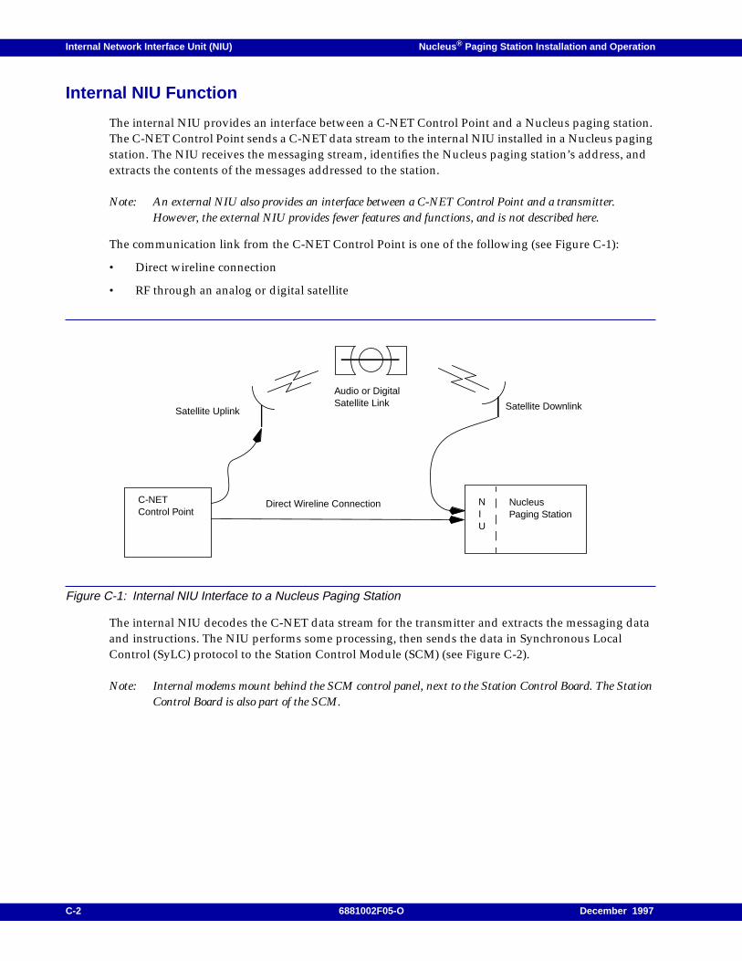
Internal Network Interface Unit (NIU) Nucleus ® Paging Station Installation and Operation
Internal NIU Function
The internal NIU provides an interface between a C-NET Control Point and a Nucleus paging station.The C-NET Control Point sends a C-NET data stream to the internal NIU installed in a Nucleus pagingstation. The NIU receives the messaging stream, identifies the Nucleus paging station’s address, andextracts the contents of the messages addressed to the station.
Note: An external NIU also provides an interface between a C-NET Control Point and a transmitter.However, the external NIU provides fewer features and functions, and is not described here.
The communication link from the C-NET Control Point is one of the following (see Figure C-1):
• Direct wireline connection
• RF through an analog or digital satellite
Figure C-1: Internal NIU Interface to a Nucleus Paging Station
The internal NIU decodes the C-NET data stream for the transmitter and extracts the messaging dataand instructions. The NIU performs some processing, then sends the data in Synchronous LocalControl (SyLC) protocol to the Station Control Module (SCM) (see Figure C-2).
Note: Internal modems mount behind the SCM control panel, next to the Station Control Board. The StationControl Board is also part of the SCM.
Satellite Uplink
Audio or DigitalSatellite Link
C-NETControl Point
Satellite Downlink
NIU
NucleusPaging Station
Direct Wireline Connection
C-2 6881002F05-O December 1997
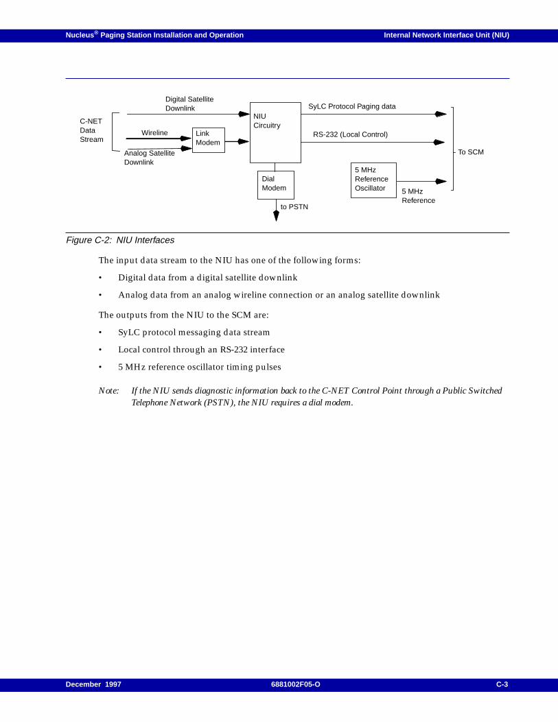
Nucleus ® Paging Station Installation and Operation Internal Network Interface Unit (NIU)
Figure C-2: NIU Interfaces
The input data stream to the NIU has one of the following forms:
• Digital data from a digital satellite downlink
• Analog data from an analog wireline connection or an analog satellite downlink
The outputs from the NIU to the SCM are:
• SyLC protocol messaging data stream
• Local control through an RS-232 interface
• 5 MHz reference oscillator timing pulses
Note: If the NIU sends diagnostic information back to the C-NET Control Point through a Public SwitchedTelephone Network (PSTN), the NIU requires a dial modem.
to PSTN
Analog SatelliteDownlink
Wireline
Digital SatelliteDownlink SyLC Protocol Paging data
C-NETDataStream
To SCM
DialModem
5 MHzReferenceOscillator
RS-232 (Local Control)
NIUCircuitry
LinkModem
5 MHzReference
December 1997 6881002F05-O C-3
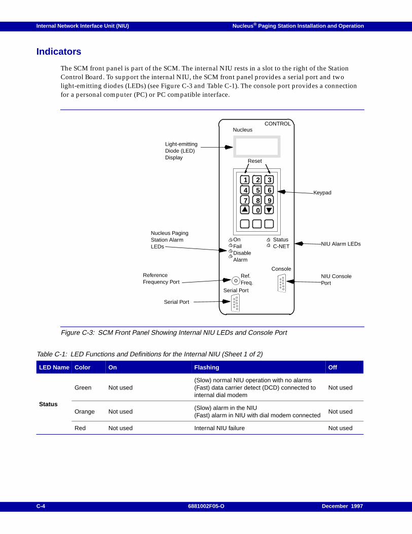
Internal Network Interface Unit (NIU) Nucleus ® Paging Station Installation and Operation
Indicators
The SCM front panel is part of the SCM. The internal NIU rests in a slot to the right of the StationControl Board. To support the internal NIU, the SCM front panel provides a serial port and twolight-emitting diodes (LEDs) (see Figure C-3 and Table C-1). The console port provides a connectionfor a personal computer (PC) or PC compatible interface.
Figure C-3: SCM Front Panel Showing Internal NIU LEDs and Console Port
Table C-1: LED Functions and Definitions for the Internal NIU (Sheet 1 of 2)
LED Name Color On Flashing Off
Status
Green Not used(Slow) normal NIU operation with no alarms(Fast) data carrier detect (DCD) connected tointernal dial modem
Not used
Orange Not used(Slow) alarm in the NIU(Fast) alarm in NIU with dial modem connected
Not used
Red Not used Internal NIU failure Not used
Serial Port
Ref.Freq.
OnFailDisableAlarm
Reset
07 8 9
654
1 2 3
NucleusCONTROL
Keypad
ReferenceFrequency Port
Light-emittingDiode (LED)Display
Nucleus PagingStation AlarmLEDs
Serial Port
StatusC-NET
Console
NIU Alarm LEDs
NIU ConsolePort
C-4 6881002F05-O December 1997
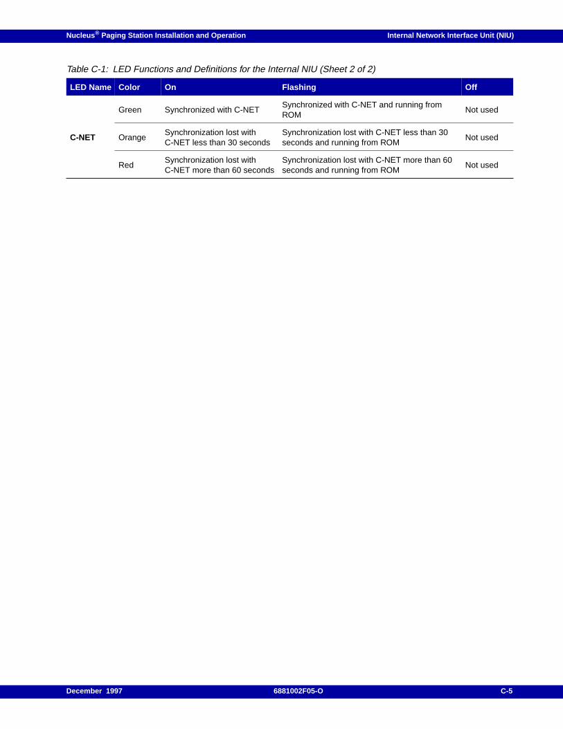
Nucleus ® Paging Station Installation and Operation Internal Network Interface Unit (NIU)
C-NET
Green Synchronized with C-NETSynchronized with C-NET and running fromROM
Not used
OrangeSynchronization lost withC-NET less than 30 seconds
Synchronization lost with C-NET less than 30seconds and running from ROM
Not used
RedSynchronization lost withC-NET more than 60 seconds
Synchronization lost with C-NET more than 60seconds and running from ROM
Not used
Table C-1: LED Functions and Definitions for the Internal NIU (Sheet 2 of 2)
LED Name Color On Flashing Off
December 1997 6881002F05-O C-5
Internal Network Interface Unit (NIU) Nucleus ® Paging Station Installation and Operation
Interfaces
The internal NIU uses the following interfaces:
• Link modem, required for a wireline interface or analog satellite downlink
• External modem adapter, required for interfaces with phones lines
• External analog receiver, required for other analog interfaces
• External digital receiver, required for digital interfaces
Link Modem Connectors
An internal NIU uses a link modem (option 443) for a wireline or analog satellite downlink input. At acustomer request, Motorola installs option 443 during manufacturing. This modem requires no siteinstallation.
Wireline interface
The wireline messaging data input for a link modem requires connection. Use the followingprocedure: to install this connection:
1. Connect the telephone tip line to Nucleus paging station backplane connector J17, pair 14, ringconductor (pin 14, NIU line +). For a list of the pinouts for J17 see Chapter 5, "Connectors andInterfaces".
2. Connect the telephone ring line to station backplane connector J17, pair 15, ring conductor (pin15, NIU line -).
External Modem Adapter
The option X774 external modem adapter provides an external interface for non-US modems. Thesemodems communicate with phone lines that comply with local code regulations.
Motorola installs option X774 on the internal NIU during manufacturing.
External Analog Receiver
Note: The external analog link receiver requires link modem option X443.
If the Nucleus paging station uses an external analog link receiver, the installation package contains acable that connects the receiver to the Nucleus paging station backplane connector J19, the linkreceiver connector.
Use the following procedure to connect the receiver:
1. Connect the link receiver audio line to backplane connector J19, pin 5. This is the link receiveraudio line (Link Rx Audio) (see Table C-2).
2. Connect link receiver squelch line (if applicable) to backplane connector J19, pin 3. This is theexternal link (Ext Link Rx Sq Ind).
C-6 6881002F05-O December 1997
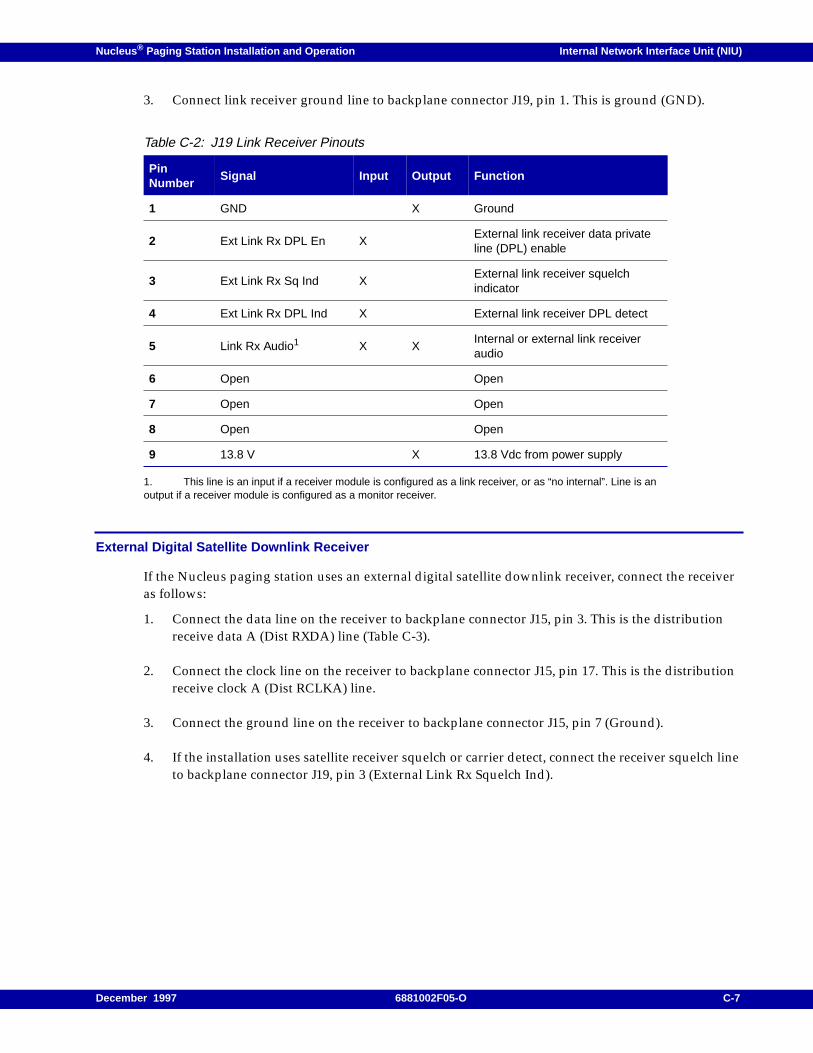
Nucleus ® Paging Station Installation and Operation Internal Network Interface Unit (NIU)
3. Connect link receiver ground line to backplane connector J19, pin 1. This is ground (GND).
External Digital Satellite Downlink Receiver
If the Nucleus paging station uses an external digital satellite downlink receiver, connect the receiveras follows:
1. Connect the data line on the receiver to backplane connector J15, pin 3. This is the distributionreceive data A (Dist RXDA) line (Table C-3).
2. Connect the clock line on the receiver to backplane connector J15, pin 17. This is the distributionreceive clock A (Dist RCLKA) line.
3. Connect the ground line on the receiver to backplane connector J15, pin 7 (Ground).
4. If the installation uses satellite receiver squelch or carrier detect, connect the receiver squelch lineto backplane connector J19, pin 3 (External Link Rx Squelch Ind).
1. This line is an input if a receiver module is configured as a link receiver, or as “no internal”. Line is anoutput if a receiver module is configured as a monitor receiver.
Table C-2: J19 Link Receiver Pinouts
PinNumber
Signal Input Output Function
1 GND X Ground
2 Ext Link Rx DPL En XExternal link receiver data privateline (DPL) enable
3 Ext Link Rx Sq Ind XExternal link receiver squelchindicator
4 Ext Link Rx DPL Ind X External link receiver DPL detect
5 Link Rx Audio1 X XInternal or external link receiveraudio
6 Open Open
7 Open Open
8 Open Open
9 13.8 V X 13.8 Vdc from power supply
December 1997 6881002F05-O C-7
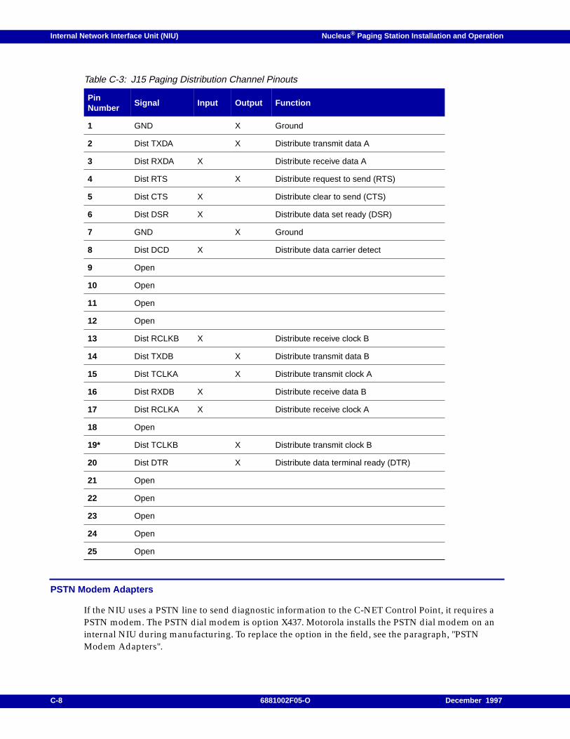
Internal Network Interface Unit (NIU) Nucleus ® Paging Station Installation and Operation
PSTN Modem Adapters
If the NIU uses a PSTN line to send diagnostic information to the C-NET Control Point, it requires aPSTN modem. The PSTN dial modem is option X437. Motorola installs the PSTN dial modem on aninternal NIU during manufacturing. To replace the option in the field, see the paragraph, "PSTNModem Adapters".
Table C-3: J15 Paging Distribution Channel Pinouts
PinNumber
Signal Input Output Function
1 GND X Ground
2 Dist TXDA X Distribute transmit data A
3 Dist RXDA X Distribute receive data A
4 Dist RTS X Distribute request to send (RTS)
5 Dist CTS X Distribute clear to send (CTS)
6 Dist DSR X Distribute data set ready (DSR)
7 GND X Ground
8 Dist DCD X Distribute data carrier detect
9 Open
10 Open
11 Open
12 Open
13 Dist RCLKB X Distribute receive clock B
14 Dist TXDB X Distribute transmit data B
15 Dist TCLKA X Distribute transmit clock A
16 Dist RXDB X Distribute receive data B
17 Dist RCLKA X Distribute receive clock A
18 Open
19* Dist TCLKB X Distribute transmit clock B
20 Dist DTR X Distribute data terminal ready (DTR)
21 Open
22 Open
23 Open
24 Open
25 Open
C-8 6881002F05-O December 1997
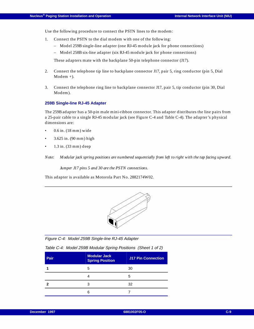
Nucleus ® Paging Station Installation and Operation Internal Network Interface Unit (NIU)
Use the following procedure to connect the PSTN lines to the modem:
1. Connect the PSTN to the dial modem with one of the following:
– Model 259B single-line adapter (one RJ-45 module jack for phone connections)
– Model 258B six-line adapter (six RJ-45 module jack for phone connections)
These adapters mate with the backplane 50-pin telephone connector (J17).
2. Connect the telephone tip line to backplane connector J17, pair 5, ring conductor (pin 5, DialModem +).
3. Connect the telephone ring line to backplane connector J17, pair 5, tip conductor (pin 30, DialModem).
259B Single-line RJ-45 Adapter
The 259B adapter has a 50-pin male mini-ribbon connector. This adapter distributes the line pairs froma 25-pair cable to a single RJ-45 modular jack (see Figure C-4 and Table C-4). The adapter’s physicaldimensions are:
• 0.6 in. (18 mm) wide
• 3.625 in. (90 mm) high
• 1.3 in. (33 mm) deep
Note: Modular jack spring positions are numbered sequentially from left to right with the tap facing upward.
Jumper J17 pins 5 and 30 are the PSTN connections.
This adapter is available as Motorola Part No. 2882174W02.
Figure C-4: Model 259B Single-line RJ-45 Adapter
Table C-4: Model 259B Modular Spring Positions (Sheet 1 of 2)
PairModular JackSpring Position
J17 Pin Connection
1 5 30
4 5
2 3 32
6 7
December 1997 6881002F05-O C-9
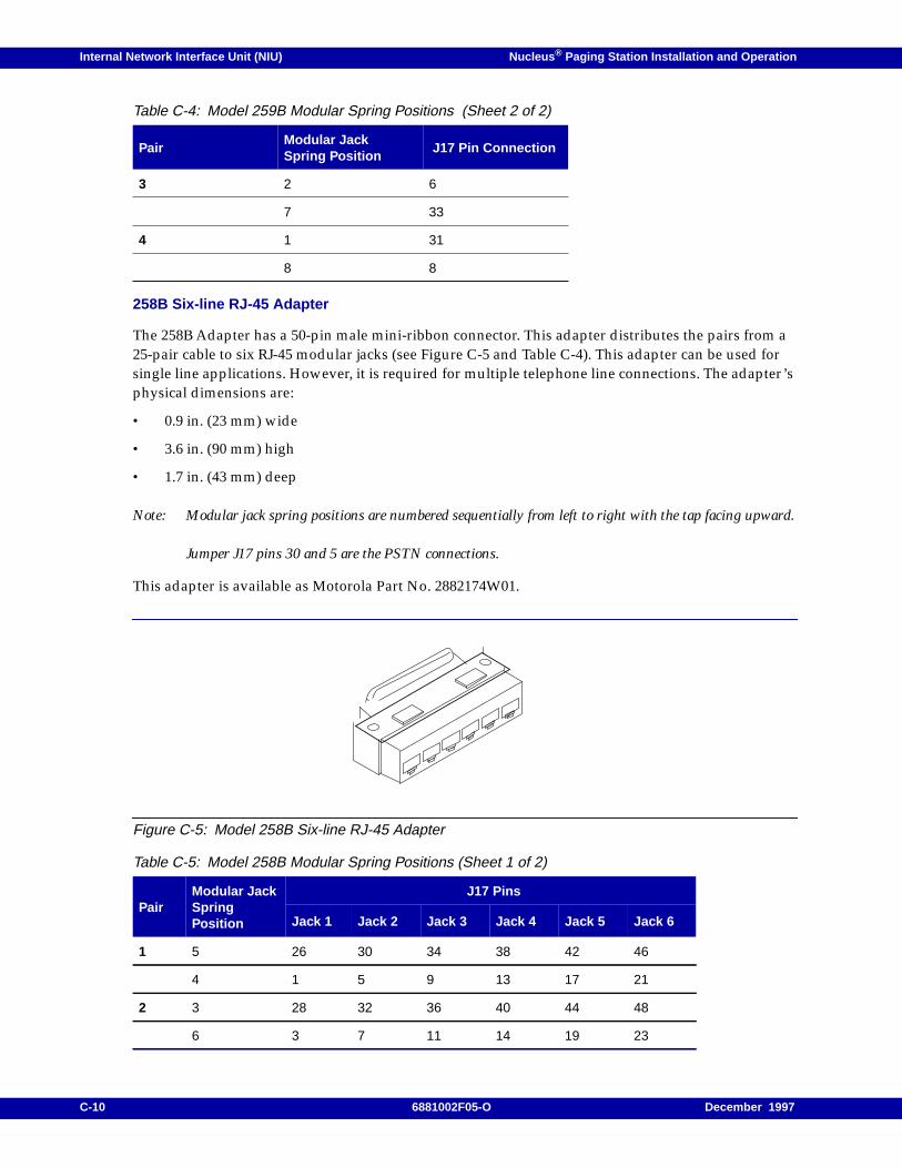
Internal Network Interface Unit (NIU) Nucleus ® Paging Station Installation and Operation
258B Six-line RJ-45 Adapter
The 258B Adapter has a 50-pin male mini-ribbon connector. This adapter distributes the pairs from a25-pair cable to six RJ-45 modular jacks (see Figure C-5 and Table C-4). This adapter can be used forsingle line applications. However, it is required for multiple telephone line connections. The adapter’sphysical dimensions are:
• 0.9 in. (23 mm) wide
• 3.6 in. (90 mm) high
• 1.7 in. (43 mm) deep
Note: Modular jack spring positions are numbered sequentially from left to right with the tap facing upward.
Jumper J17 pins 30 and 5 are the PSTN connections.
This adapter is available as Motorola Part No. 2882174W01.
Figure C-5: Model 258B Six-line RJ-45 Adapter
3 2 6
7 33
4 1 31
8 8
Table C-5: Model 258B Modular Spring Positions (Sheet 1 of 2)
PairModular JackSpringPosition
J17 Pins
Jack 1 Jack 2 Jack 3 Jack 4 Jack 5 Jack 6
1 5 26 30 34 38 42 46
4 1 5 9 13 17 21
2 3 28 32 36 40 44 48
6 3 7 11 14 19 23
Table C-4: Model 259B Modular Spring Positions (Sheet 2 of 2)
PairModular JackSpring Position
J17 Pin Connection
C-10 6881002F05-O December 1997
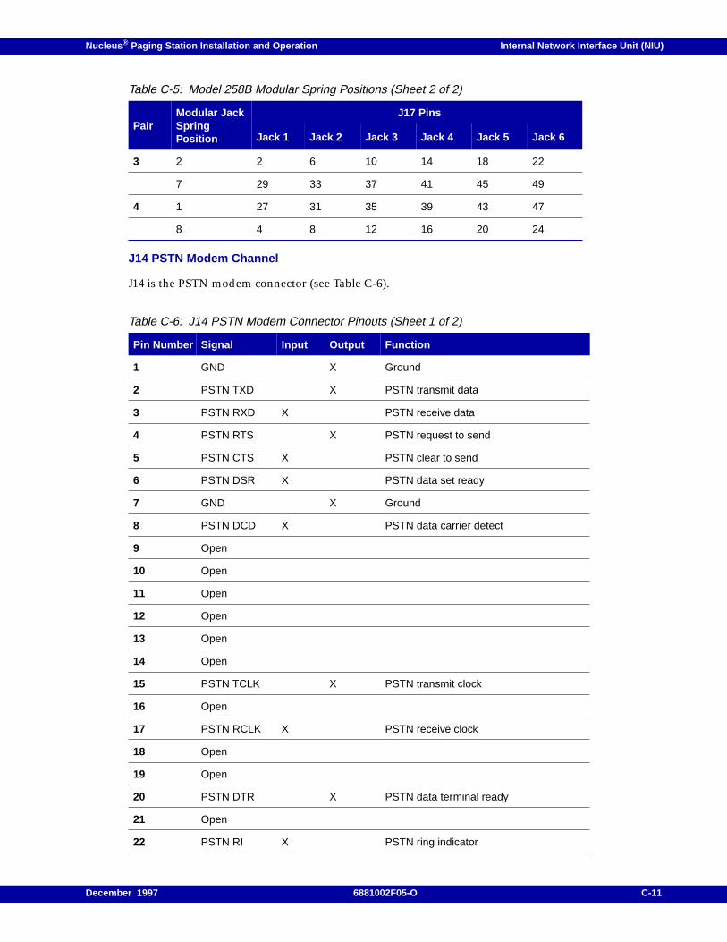
Nucleus ® Paging Station Installation and Operation Internal Network Interface Unit (NIU)
J14 PSTN Modem Channel
J14 is the PSTN modem connector (see Table C-6).
3 2 2 6 10 14 18 22
7 29 33 37 41 45 49
4 1 27 31 35 39 43 47
8 4 8 12 16 20 24
Table C-6: J14 PSTN Modem Connector Pinouts (Sheet 1 of 2)
Pin Number Signal Input Output Function
1 GND X Ground
2 PSTN TXD X PSTN transmit data
3 PSTN RXD X PSTN receive data
4 PSTN RTS X PSTN request to send
5 PSTN CTS X PSTN clear to send
6 PSTN DSR X PSTN data set ready
7 GND X Ground
8 PSTN DCD X PSTN data carrier detect
9 Open
10 Open
11 Open
12 Open
13 Open
14 Open
15 PSTN TCLK X PSTN transmit clock
16 Open
17 PSTN RCLK X PSTN receive clock
18 Open
19 Open
20 PSTN DTR X PSTN data terminal ready
21 Open
22 PSTN RI X PSTN ring indicator
Table C-5: Model 258B Modular Spring Positions (Sheet 2 of 2)
PairModular JackSpringPosition
J17 Pins
Jack 1 Jack 2 Jack 3 Jack 4 Jack 5 Jack 6
December 1997 6881002F05-O C-11

Internal Network Interface Unit (NIU) Nucleus ® Paging Station Installation and Operation
23 Open
24 Open
25 Open
Table C-6: J14 PSTN Modem Connector Pinouts (Sheet 2 of 2)
Pin Number Signal Input Output Function
C-12 6881002F05-O December 1997
Nucleus ® Paging Station Installation and Operation / Appendix D
RF-Baton! Transmitter Controller InterfaceD
This appendix describes the interface between a Nucleus paging station and an RF-Baton! (RF-B!)transmitter controller. The interface is the Wildcard Interface Board (WIB) that resides in the Nucleuspaging station. This chapter contains the following information:
Overview, D-2
WIB Interface, D-3Synchronous Local Control (SyLC) Protocol, D-3WIB Inputs, D-4WIB Alarm Relay, D-4
Replacement Procedure, D-5Replacement Procedure, D-5Post-replacement Optimization Procedure, D-6
December 1997 6881002F05-O D-1

RF-Baton! Transmitter Controller Interface Nucleus ® Paging Station Installation and Operation
Overview
The RF-B! transmitter controller provides an interface between the WMG-Administrator! and theNucleus paging station. The RF-B! transmitter controller also provides synchronization timing for thetransmitter in the network from the Global Positioning System (GPS).
For a complete description of the RF-B! transmitter controller, see RF-Baton! Transmitter ControllerInstallation and Operation Guide, 6880497G05.
D-2 6881002F05-O December 1997
Nucleus ® Paging Station Installation and Operation RF-Baton! Transmitter Controller Interface
WIB Interface
The WIB interface consists of the following elements:
• Eight inputs that the Nucleus paging station uses to monitor external site equipment
• Eight open-collector outputs which may be used to indicate alarms
The WIB outputs drives the following types of transistor-transistor (TTL) and complementary metal-oxide semiconductor (CMOS) logic:
• Low-power Schottkey (LS) TTL
• Advanced Low-power Schottkey (ALS) TTL
• Fast TTL
• CMOS logic
Note: The WIB outputs cannot drive standard TTL reliably. The low voltage specified for standard TTL ismarginal on the WIB.
Synchronous Local Control (SyLC) Protocol
The WIB uses Synchronous Local Control (SyLC) protocol. The SyLC protocol is synchronous and usesthree TTL-compatible lines:
• Tx Baud Clock—runs at the symbol rate and indicates the symbol boundaries.
• Tx Data Clock—runs at the bit rate and clocks Tx Data bits from the Tx Data Line.
• Tx Data—runs at the clocked rate from Tx Data Clock
Note: In the 2-level FLEX messaging, the baud clock and the data clock run at equal rates. During idleconditions, the baud and data clocks go to a high state.
External key request (Ext Key Req) provides external control. Ext Key Req goes active 250 ms beforevalid data. The Ext Key Req line is programmable for active high or active low.
Note: For POCSAG and FLEX operation, the FLEX Select line must be pulled high. To do this, connect pin18 of the interface through the 10 kW pullup resistor to pin 8.
Each pullup resistor on a WIB output is 470 Ohm. The output of the resistor acts as a divider when theoutput is used as an external pullup (see Figure D-1). An external pullup resistor with a value of10 kOhm or more minimizes the output voltage increase. A collector current (Ic) ≤ 12 mA ensures thatVout is ≤ 0.8 V for logic integrity.
December 1997 6881002F05-O D-3
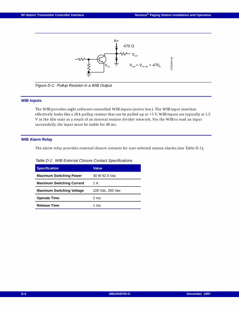
RF-Baton! Transmitter Controller Interface Nucleus ® Paging Station Installation and Operation
Figure D-1: Pullup Resistor in a WIB Output
WIB Inputs
The WIB provides eight software-controlled WIB inputs (active low). The WIB input interfaceeffectively looks like a 28 k pullup resistor that can be pulled up to +5 V. WIB inputs are typically at 1.5V in the idle state as a result of an internal resistor divider network. For the WIB to read an inputsuccessfully, the input must be stable for 40 ms.
WIB Alarm Relay
The alarm relay provides external closure contacts for user-selected station alarms (see Table D-1).
Table D-1: WIB External Closure Contact Specifications
Specification Value
Maximum Switching Power 30 W 62.5 Vac
Maximum Switching Current 1 A
Maximum Switching Voltage 220 Vdc, 250 Vac
Operate Time 2 ms
Release Time 1 ms
A+470 O
Vout = Vce sat + 470lcVce
Vout
2F05
SR
H-0
8
D-4 6881002F05-O December 1997
Nucleus ® Paging Station Installation and Operation RF-Baton! Transmitter Controller Interface
Replacement Procedure
The WIB resides behind the control front panel to the right of the Station Control Board when viewedfrom the front of the station. This section describes replacement.
Replacement Procedure
Use this procedure to replace the WIB:
1. Connect a antistatic wrist strap connector to one of the two ground jacks on the cage.
2. If the Nucleus paging station has AC power with a battery revert option (X30 or X43), disconnectthe batteries.
3. Turn off power by turning the power supply On-Off switch(es) to Off (press the 0 side of theswitch).
4. Remove the mounting screws from the very top and very bottom of the Station Control Module(SCM) front panel. Pull the SCM front panel outward until the ribbon cable connector isaccessible.
5. Disconnect the ribbon cable connector from the rear of the SCM front panel to the Station ControlBoard, and set aside the SCM front panel.
6. Remove the WIB (on right side in cavity behind SCM front panel) by pulling it straight out.
7. Set all jumpers on the replacement WIB to match those on the faulty WIB. These include input-output impedance matching jumpers, 2-wire or 4-wire selection jumper, and DC remote controlselection jumpers.
8. Install the replacement WIB by sliding the it into the cage. Seat the WIB connectors firmly in thebackplane.
9. Reconnect ribbon cable from Station Control Board to the rear of the SCM front panel.
10. Replace the SCM front panel and secure with two mounting screws removed in Step 4.
11. Restore power by turning the power supply On-Off switch(es) to On (press the 1 side of theswitch).
12. If the Nucleus paging station has AC power with a battery revert option (X30 or X43), reconnectthe batteries.
CAUTION
Do not force the WIB into the backplane connector. Use moderate pressure and rock the WIBslightly until it is completely seated.
December 1997 6881002F05-O D-5

RF-Baton! Transmitter Controller Interface Nucleus ® Paging Station Installation and Operation
Post-replacement Optimization Procedure
The WIB does not require a post-replacement procedure.
D-6 6881002F05-O December 1997
Nucleus ® Paging Station Installation and Operation / Appendix E
Receivers E
This appendix describes the function, configuration, and replacement procedures for the receiversused in a Nucleus paging station. This appendix describes link receivers and monitor receivers.
The contents of this appendix include:
Operation, E-3Overview, E-3Link Receiver, E-3Monitor Receiver, E-4Circuitry, E-4Receiver Circuitry, E-5CRIB Circuitry, E-5
Receiver Replacement Procedures, E-6Antistatic Precautions, E-6External Monitor Receiver Connector, E-7External Analog Link Receiver Connector, E-7Internal Monitor Receiver, E-8CRIB Replacement, E-11900 MHz Receiver Replacement, E-16Midband, 280 MHz, VHF, and UHF Receiver Replacement, E-16
Testing and Tuning, E-19Required Test Equipment, E-19Preparing Test Equipment, E-19Proper Alignment Frequency–VHF and Midband, E-21Tuning Procedure–VHF and Midband, E-21Proper Alignment Frequency–UHF Preselector, E-22Tuning Procedure–UHF Preselector, E-23Proper Alignment Frequency–280 MHz Preselector, E-23Required Test Equipment–280 MHz Preselector, E-24Preparing Equipment–280 MHz Preselector, E-24Tuning Procedure–280 MHz Preselector, E-25
December 1997 6881002F05-O E-1
Receivers Nucleus ® Paging Station Installation and Operation
The Nucleus paging station uses two types of receiver:
• A link receiver provides an interface to a link transmitter.
• A monitor receiver receives maintenance messages from paging stations, including the pagingstation at the same site, for transmission to a controller.
These receivers comprise the following (see Table 1-7 and Table 1-8):
• Midband (72–76 MHz) link receiver only
• VHF (132–154 MHz and 150–174 MHz) link receivers and monitor receivers
• 280 MHz (276–286 MHz) monitor receiver only
• UHF (403–433 MHz, 438–470 MHz, 470–494 MHz, and 494–520 MHz) link receivers and monitorreceivers
• 900 MHz (922–941 MHz and 941–960 MHz) link receivers and monitor receivers
Configure a receiver as a monitor receiver or a link receiver through the Configuration (<CNFG>)menu, RX TYPE submenu.
E-2 6881002F05-O December 1997
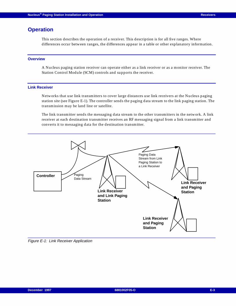
Nucleus ® Paging Station Installation and Operation Receivers
Operation
This section describes the operation of a receiver. This description is for all five ranges. Wheredifferences occur between ranges, the differences appear in a table or other explanatory information.
Overview
A Nucleus paging station receiver can operate either as a link receiver or as a monitor receiver. TheStation Control Module (SCM) controls and supports the receiver.
Link Receiver
Networks that use link transmitters to cover large distances use link receivers at the Nucleus pagingstation site (see Figure E-1). The controller sends the paging data stream to the link paging station. Thetransmission may be land line or satellite.
The link transmitter sends the messaging data stream to the other transmitters in the network. A linkreceiver at each destination transmitter receives an RF messaging signal from a link transmitter andconverts it to messaging data for the destination transmitter.
Figure E-1: Link Receiver Application
Controller
Link Receiverand Link PagingStation
Link Receiverand PagingStation
Link Receiverand PagingStation
PagingData Stream
Paging DataStream from LinkPaging Station toa Link Receiver
December 1997 6881002F05-O E-3
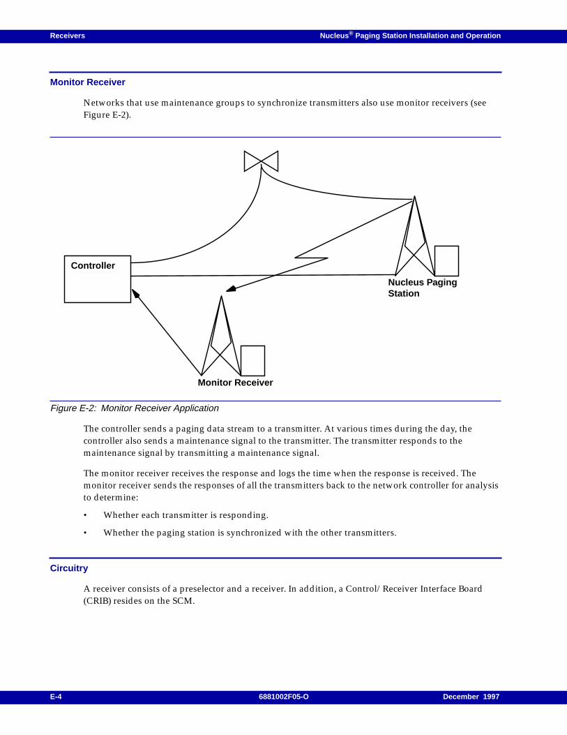
Receivers Nucleus ® Paging Station Installation and Operation
Monitor Receiver
Networks that use maintenance groups to synchronize transmitters also use monitor receivers (seeFigure E-2).
Figure E-2: Monitor Receiver Application
The controller sends a paging data stream to a transmitter. At various times during the day, thecontroller also sends a maintenance signal to the transmitter. The transmitter responds to themaintenance signal by transmitting a maintenance signal.
The monitor receiver receives the response and logs the time when the response is received. Themonitor receiver sends the responses of all the transmitters back to the network controller for analysisto determine:
• Whether each transmitter is responding.
• Whether the paging station is synchronized with the other transmitters.
Circuitry
A receiver consists of a preselector and a receiver. In addition, a Control/Receiver Interface Board(CRIB) resides on the SCM.
Controller
Monitor Receiver
Nucleus PagingStation
E-4 6881002F05-O December 1997
Nucleus ® Paging Station Installation and Operation Receivers
Preselector Assembly
The preselector assembly provides a bandpass filter for the receive RF input signal. The filter assemblyis mounted on the front of the receiver housing and provides mini-UHF connectors for input from thereceive antenna and output to the receiver. The filter assembly has tuning screws for filter tuning. Thetuning procedures for the receivers are described in paragraph, "Tuning Procedure–VHF andMidband", paragraph, "Tuning Procedure–UHF Preselector", and paragraph, "Tuning Procedure–280MHz Preselector".
Note: The 900 MHz receiver does not use a preselector.
Receiver Circuitry
The receiver contains the following circuitry:
• The receiver front end circuitry filters and amplifies the receiver RF signal performs the firstdown conversion for the receive RF signal.
• The custom receiver integrated circuit (IC) circuitry is a custom IC. It performs the second downconversion. It also filters and amplifies the receive signal and performs A/D conversion on thereceive signal.
• The synthesizer circuitry contains a phase-locked loop (PLL).
• The voltage controlled oscillator (VCO) circuitry contains two VCOs and a band-shift switch. TheVCO circuitry generates signal that passes to the first low injection amplifier in the receiver frontend circuitry.
• The address decode and A/D converter circuitry decodes addresses provide memory board andchip select signals. This circuitry also converts analog status signals to digital format for transferto the SCM.
• The local power supply regulation circuit accepts +14.2 Vdc input and creates +10 Vdc and+5 Vdc operating voltages.
CRIB Circuitry
The CRIB contains the following circuitry:
• The digital signal processing circuitry converts the digital signal from the receiver to the desiredaudio output.
• The interface circuitry controls the audio path of the desired audio signal.
The CRIB processes the digitized receive signal into an analog audio output. For a link receiver, theCRIB gates the audio to LINK_RX_AUDIO. For a monitor receiver, the CRIB gates the audio toMONITOR_RX_AUDIO.
By default, the audio output data is not inverted. To invert the data, use the Nucleus paging stationSCM front panel (Receiver menu).
December 1997 6881002F05-O E-5
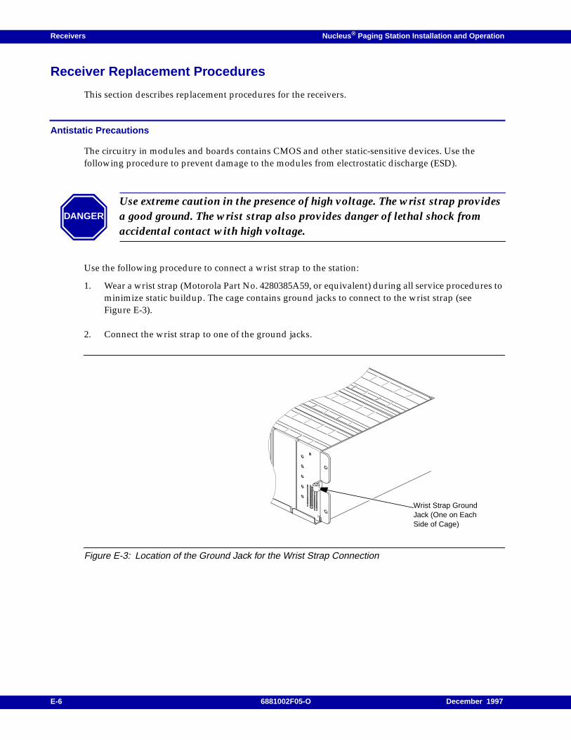
Receivers Nucleus ® Paging Station Installation and Operation
Receiver Replacement Procedures
This section describes replacement procedures for the receivers.
Antistatic Precautions
The circuitry in modules and boards contains CMOS and other static-sensitive devices. Use thefollowing procedure to prevent damage to the modules from electrostatic discharge (ESD).
Use the following procedure to connect a wrist strap to the station:
1. Wear a wrist strap (Motorola Part No. 4280385A59, or equivalent) during all service procedures tominimize static buildup. The cage contains ground jacks to connect to the wrist strap (seeFigure E-3).
2. Connect the wrist strap to one of the ground jacks.
Figure E-3: Location of the Ground Jack for the Wrist Strap Connection
DANGER
Use extreme caution in the presence of high voltage. The wrist strap providesa good ground. The wrist strap also provides danger of lethal shock fromaccidental contact with high voltage.
Wrist Strap GroundJack (One on EachSide of Cage)
E-6 6881002F05-O December 1997
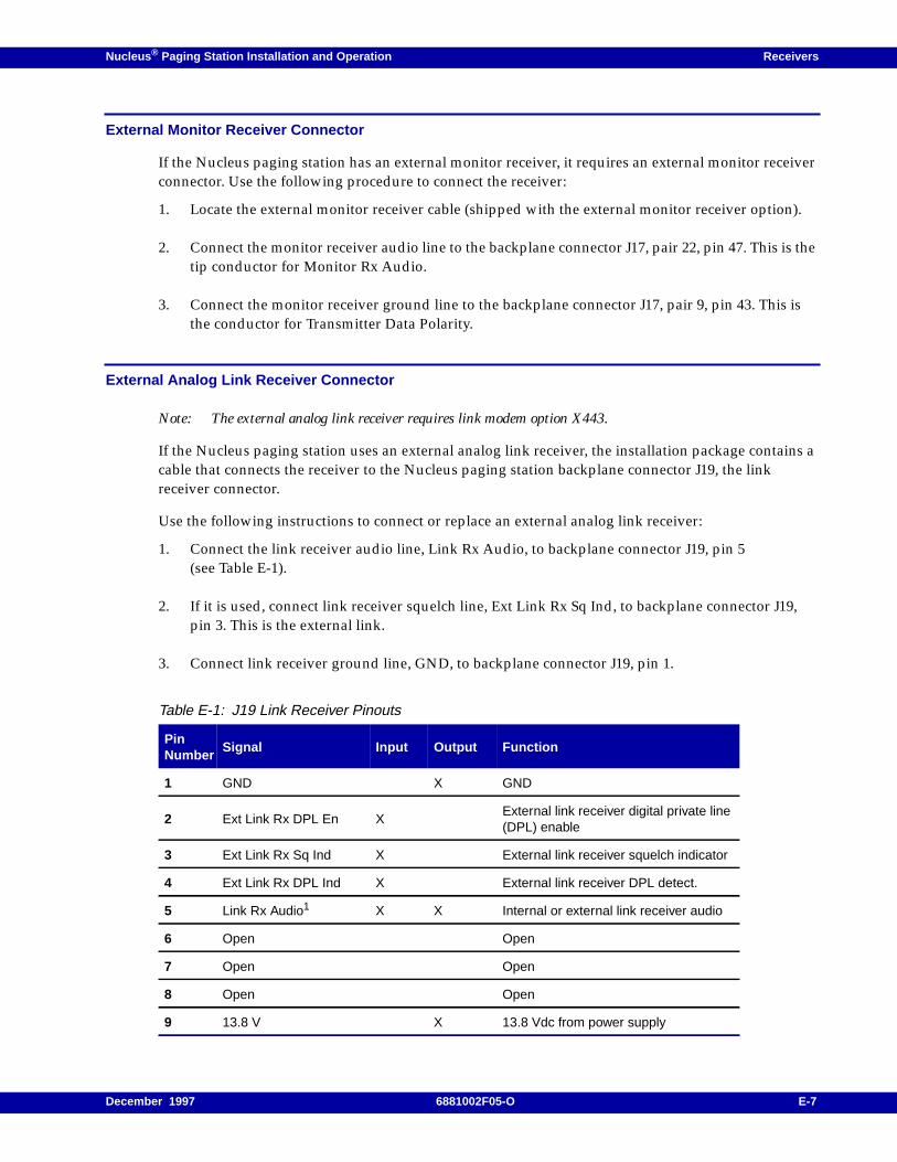
Nucleus ® Paging Station Installation and Operation Receivers
External Monitor Receiver Connector
If the Nucleus paging station has an external monitor receiver, it requires an external monitor receiverconnector. Use the following procedure to connect the receiver:
1. Locate the external monitor receiver cable (shipped with the external monitor receiver option).
2. Connect the monitor receiver audio line to the backplane connector J17, pair 22, pin 47. This is thetip conductor for Monitor Rx Audio.
3. Connect the monitor receiver ground line to the backplane connector J17, pair 9, pin 43. This isthe conductor for Transmitter Data Polarity.
External Analog Link Receiver Connector
Note: The external analog link receiver requires link modem option X443.
If the Nucleus paging station uses an external analog link receiver, the installation package contains acable that connects the receiver to the Nucleus paging station backplane connector J19, the linkreceiver connector.
Use the following instructions to connect or replace an external analog link receiver:
1. Connect the link receiver audio line, Link Rx Audio, to backplane connector J19, pin 5(see Table E-1).
2. If it is used, connect link receiver squelch line, Ext Link Rx Sq Ind, to backplane connector J19,pin 3. This is the external link.
3. Connect link receiver ground line, GND, to backplane connector J19, pin 1.
Table E-1: J19 Link Receiver Pinouts
PinNumber
Signal Input Output Function
1 GND X GND
2 Ext Link Rx DPL En XExternal link receiver digital private line(DPL) enable
3 Ext Link Rx Sq Ind X External link receiver squelch indicator
4 Ext Link Rx DPL Ind X External link receiver DPL detect.
5 Link Rx Audio1 X X Internal or external link receiver audio
6 Open Open
7 Open Open
8 Open Open
9 13.8 V X 13.8 Vdc from power supply
December 1997 6881002F05-O E-7

Receivers Nucleus ® Paging Station Installation and Operation
Internal Monitor Receiver
This section describes the replacement procedure for an internal monitor receiver in a Nucleus pagingstation or a Nucleus paging station with Advanced Control (NAC).
Software
For a Nucleus paging station, the application software must be Version 3.21 or higher to use with thereceiver module (see Chapter 9, "SCM Station Alarms, Status, Troubleshooting, and Alignment",Chapter , "Station Status").
For a NAC station, the NAC firmware must be Version 3.2x or higher to use with the receiver module(see Chapter 7, "Basic Keypad Procedures", Table 7-2).
Preparation
Use the following procedure to install or replace the monitor receiver:
1. If the station has AC power with a battery revert option (X30 or X43), use the followingprocedure:
a. Disconnect the batteries.
b. Turn the power On-Off switch(es) to Off (press the 0 side of the switch).
c. Remove the module or board by following the instructions in the sections that follow.
2. Keep each spare modules in an antistatic bag for storage and transporting. Pack modules inantistatic materials to ship hem.
3. To restore power, use the following procedure:
a. Turn the power On-Off switch(es) to On (press the 1 side of the switch).
b. Reconnect the batteries.
4. At the rear of the station, route the receive input RF cable from the back of the antenna bracketthrough the hold in the station backplane (see Figure E-4):
a. Route the 900-MHz cable through a hole in the backplane.
b. Route the VHF, 280-MHz or UHF cable around the side of the backplane.
1. Pin 5 is an input if a receiver is configured as a link receiver, or as “no internal”. Line is an output if areceiver is configured as a monitor receiver.
DANGER
Do not insert or remove a module or board with the power turned on.Inserting or removing a module with the power turned on may result indamage to the station or the module.
In high power Nucleus paging stations, turn off both power supplies
E-8 6881002F05-O December 1997
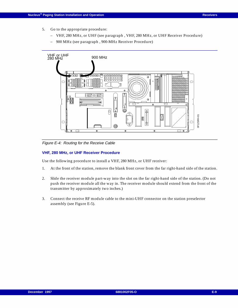
Nucleus ® Paging Station Installation and Operation Receivers
5. Go to the appropriate procedure:
– VHF, 280 MHz, or UHF (see paragraph , VHF, 280 MHz, or UHF Receiver Procedure)
– 900 MHz (see paragraph , 900-MHz Receiver Procedure)
Figure E-4: Routing for the Receive Cable
VHF, 280 MHz, or UHF Receiver Procedure
Use the following procedure to install a VHF, 280 MHz, or UHF receiver:
1. At the front of the station, remove the blank front cover from the far right-hand side of the station.
2. Slide the receiver module part-way into the slot on the far right-hand side of the station. (Do notpush the receiver module all the way in. The receiver module should extend from the front of thetransmitter by approximately two inches.)
3. Connect the receive RF module cable to the mini-UHF connector on the station preselectorassembly (see Figure E-5).
900 MHzVHF or UHF280 MHz
0F12
SR
H-0
1
December 1997 6881002F05-O E-9
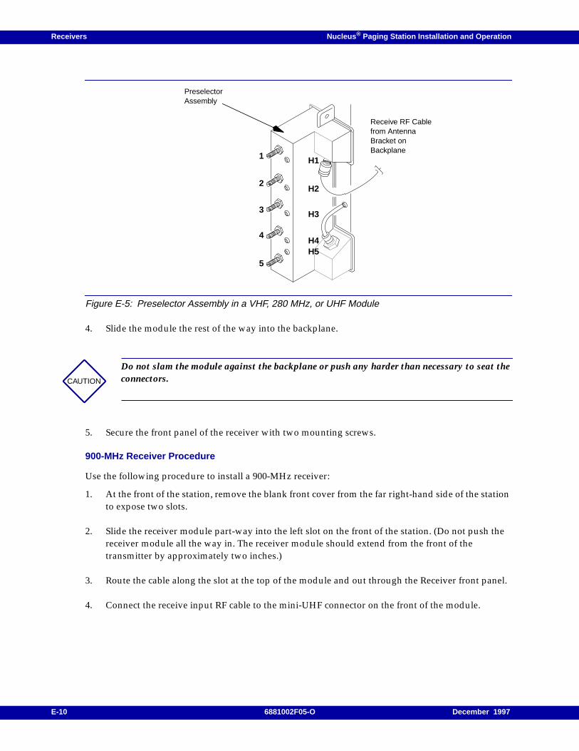
Receivers Nucleus ® Paging Station Installation and Operation
Figure E-5: Preselector Assembly in a VHF, 280 MHz, or UHF Module
4. Slide the module the rest of the way into the backplane.
5. Secure the front panel of the receiver with two mounting screws.
900-MHz Receiver Procedure
Use the following procedure to install a 900-MHz receiver:
1. At the front of the station, remove the blank front cover from the far right-hand side of the stationto expose two slots.
2. Slide the receiver module part-way into the left slot on the front of the station. (Do not push thereceiver module all the way in. The receiver module should extend from the front of thetransmitter by approximately two inches.)
3. Route the cable along the slot at the top of the module and out through the Receiver front panel.
4. Connect the receive input RF cable to the mini-UHF connector on the front of the module.
CAUTION
Do not slam the module against the backplane or push any harder than necessary to seat theconnectors.
PreselectorAssembly
H1
Receive RF Cablefrom AntennaBracket onBackplane
1
2
3
4
5
H2
H3
H4H5
E-10 6881002F05-O December 1997
Nucleus ® Paging Station Installation and Operation Receivers
5. Slide the module into the backplane.
6. Secure the front panel of the receiver with two mounting screws.
7. Secure the half-width blank front panel with two mounting screws over the open slot.
CRIB Replacement
The CRIB board is required for the receiver. Use one of the following procedures to install or replacethe CRIB board:
• Nucleus paging station
• NAC paging station
• C-NET and NIU control or RF-Baton! transmitter controller
• Nucleus Advanced Control (NAC) control
Note: The station power supplies should still be turned off.
CRIB for a Nucleus Paging Station
Use the following procedure to install a CRIB in a Nucleus paging:
1. Remove the mounting screws from the very top and very bottom of Station Control Module(SCM) front panel.
Note: The SCM consists of the SCM front panel and the Station Control Board (SCB). This procedure refersto the SCB.
2. Pull the SCM front panel out until the ribbon cable connector is accessible.
3. Disconnect the ribbon cable connector from the SCB, and set the SCM front panel aside.
4. Insert the board-pulling arm into the notch at the bottom front of the SCB.
5. Pull the SCB straight out.
6. In the package, locate the CRIB standoffs. Pinch each standoff and insert it into one of fourstandoff holes in the CRIB (see Figure E-6).
CAUTION
Do not slam the module against the backplane or push any harder than necessary to seat theconnectors.
December 1997 6881002F05-O E-11
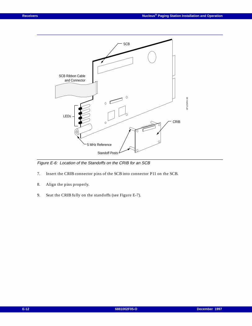
Receivers Nucleus ® Paging Station Installation and Operation
Figure E-6: Location of the Standoffs on the CRIB for an SCB
7. Insert the CRIB connector pins of the SCB into connector P11 on the SCB.
8. Align the pins properly.
9. Seat the CRIB fully on the standoffs (see Figure E-7).
Standoff Posts
CRIB
0F
12
SR
H-3
0
SCB
LEDs
SCB Ribbon Cableand Connector
5 MHz Reference
E-12 6881002F05-O December 1997
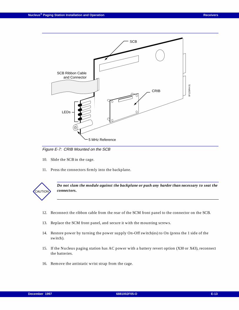
Nucleus ® Paging Station Installation and Operation Receivers
Figure E-7: CRIB Mounted on the SCB
10. Slide the SCB in the cage.
11. Press the connectors firmly into the backplane.
12. Reconnect the ribbon cable from the rear of the SCM front panel to the connector on the SCB.
13. Replace the SCM front panel, and secure it with the mounting screws.
14. Restore power by turning the power supply On-Off switch(es) to On (press the 1 side of theswitch).
15. If the Nucleus paging station has AC power with a battery revert option (X30 or X43), reconnectthe batteries.
16. Remove the antistatic wrist strap from the cage.
CAUTION
Do not slam the module against the backplane or push any harder than necessary to seat theconnectors.
CRIB
SCB
0F12
SR
H-3
1
LEDs
SCB Ribbon Cableand Connector
5 MHz Reference
December 1997 6881002F05-O E-13
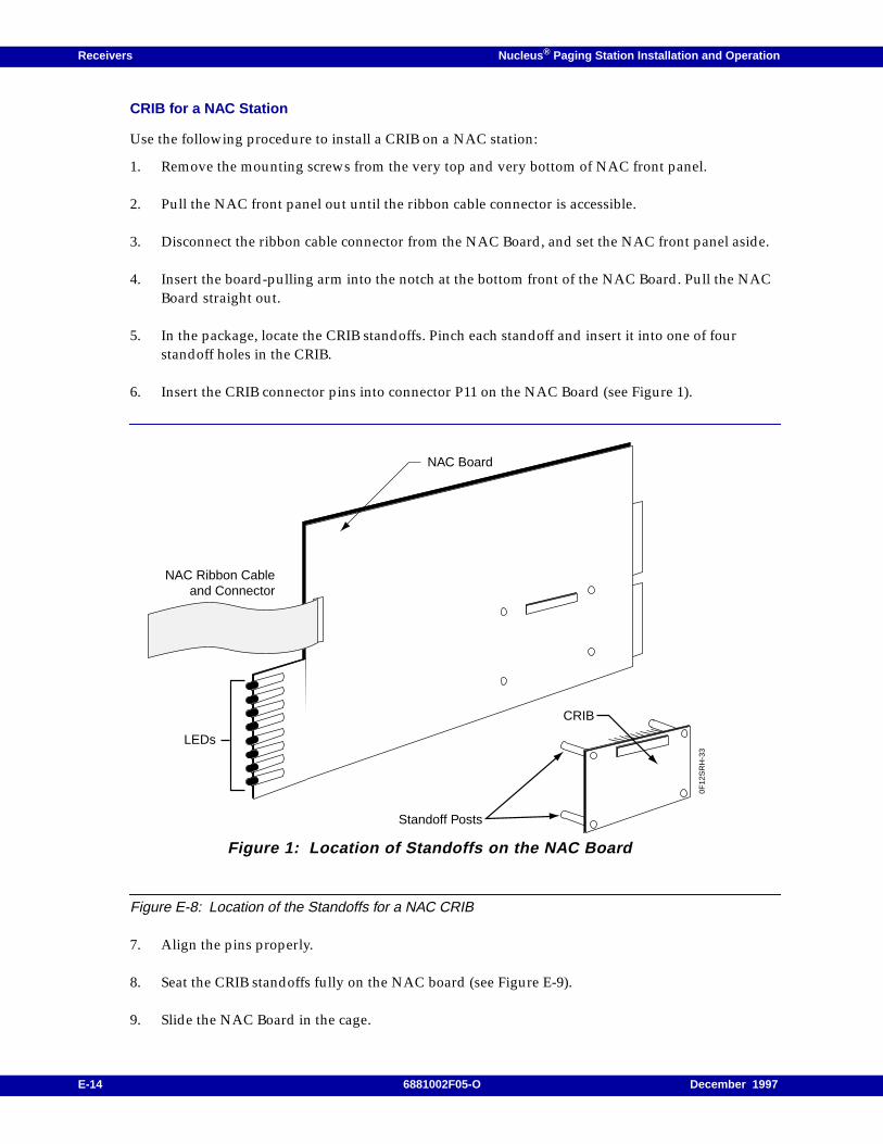
Receivers Nucleus ® Paging Station Installation and Operation
CRIB for a NAC Station
Use the following procedure to install a CRIB on a NAC station:
1. Remove the mounting screws from the very top and very bottom of NAC front panel.
2. Pull the NAC front panel out until the ribbon cable connector is accessible.
3. Disconnect the ribbon cable connector from the NAC Board, and set the NAC front panel aside.
4. Insert the board-pulling arm into the notch at the bottom front of the NAC Board. Pull the NACBoard straight out.
5. In the package, locate the CRIB standoffs. Pinch each standoff and insert it into one of fourstandoff holes in the CRIB.
6. Insert the CRIB connector pins into connector P11 on the NAC Board (see Figure 1).
Figure E-8: Location of the Standoffs for a NAC CRIB
7. Align the pins properly.
8. Seat the CRIB standoffs fully on the NAC board (see Figure E-9).
9. Slide the NAC Board in the cage.
Figure 1: Location of Standoffs on the NAC Board
Standoff Posts
CRIB
NAC Board
0F12
SR
H-3
3
LEDs
NAC Ribbon Cableand Connector
E-14 6881002F05-O December 1997
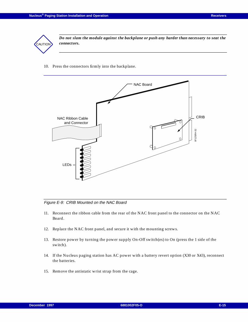
Nucleus ® Paging Station Installation and Operation Receivers
10. Press the connectors firmly into the backplane.
Figure E-9: CRIB Mounted on the NAC Board
11. Reconnect the ribbon cable from the rear of the NAC front panel to the connector on the NACBoard.
12. Replace the NAC front panel, and secure it with the mounting screws.
13. Restore power by turning the power supply On-Off switch(es) to On (press the 1 side of theswitch).
14. If the Nucleus paging station has AC power with a battery revert option (X30 or X43), reconnectthe batteries.
15. Remove the antistatic wrist strap from the cage.
CAUTION
Do not slam the module against the backplane or push any harder than necessary to seat theconnectors.
CRIB
NAC Board
0F12
SR
H-3
2
LEDs
NAC Ribbon Cableand Connector
December 1997 6881002F05-O E-15
Receivers Nucleus ® Paging Station Installation and Operation
900 MHz Receiver Replacement
Use this procedure to replace a 900 MHz receiver:
1. Connect a antistatic wrist strap connector to one of the two ground jacks in the cage.
2. If the station has AC power with a battery revert option (X30 or X43), disconnect the batteries.
3. Turn the power On/Off switch(es) to the Off position (press the 0 side of the switch).
4. Remove the mounting screws from the top and bottom of the receiver.
5. Disconnect mini-UHF connector on RF cable connecting receiver to the antenna.
6. Remove faulty module from cage.
7. Install replacement receiver by sliding module into cage.
8. Route the RF cable connecting the receiver to the antenna in the slot on top of the modulehousing.
9. Firmly press the module connector into the backplane.
10. Connect the RF cable from the antenna.
11. Secure the reference module with two mounting screws removed in Step 4.
12. Restore power by turning the power supply On-Off switch(es) to On (press the 1 side of theswitch).
13. If the Nucleus paging station has AC power with a battery revert option (X30 or X43), thenreconnect the batteries.
14. Remove the antistatic wrist strap from the cage.
Midband, 280 MHz, VHF, and UHF Receiver Replacement
Midband, VHF, and UHF receivers consist of two field replaceable units (FRUs):
• Preselector assembly attached to the antenna bracket
• Receiver
CAUTION
Replace the module in the second from the right side of the station cage. Do not slamthe module against the backplane or push any harder than necessary to seat theconnectors.
E-16 6881002F05-O December 1997
Nucleus ® Paging Station Installation and Operation Receivers
Use the following procedures to replace the assembly and the module. If the receiver has a preselector,perform the preselector tuning procedure that follows.
1. Connect a antistatic wrist strap connector to one of the two ground jacks in the cage.
2. If the station has AC power with a battery revert option (X30 or X43), disconnect the batteries.
3. Turn the power On/Off switch(es) to the Off position (press the 0 side of the switch). Continuewith the procedure to replace the receiver.
Replace the Receiver
Use the following procedure to replace the receiver:
1. Remove the mounting screws from the very top and very bottom of the receiver.
2. Slide the module out just far enough to disconnect the mini-UHF connector on the RF cable (RFinput to the module) connected to the preselector assembly.
3. Disconnect cable (mini-UHF connector) connected to receiver.
4. Remove nine (9) TORX head screws that secure the receiver to the module housing. Note thelocation of foam insulating pad under the Voltage controlled oscillator (VCO) portion of receiver.
5. Remove the faulty board and replace it with a known good board. Position the foam insulatingpad behind the VCO.
6. Secure the board using the TORX head screws removed in Step 4. Reconnect RF cable to mini-UHF connector on board.
7. Install the replacement receiver by sliding the module into the cage. Push the module in to withinapproximately 2 in. of complete installation.
8. Connect the RF input cable to the mini-UHF connector on the Preselector assembly.
9. Slide the module in completely and firmly press the module connector into the backplane.
10. Secure with the two screws in the top and bottom of the module.
11. Restore power by turning the power supply On-Off switch(es) to On (press the 1 side of theswitch).
12. If the Nucleus paging station has AC power with a battery revert option (X30 or X43), thenreconnect the batteries.
CAUTION
Do not slam the module against the backplane or push any harder than necessary toseat the connectors.
December 1997 6881002F05-O E-17
Receivers Nucleus ® Paging Station Installation and Operation
Replace the Preselector Assembly
Use the following procedure to replace the Preselector Assembly:
1. Disconnect cables (mini-UHF connectors) from assembly.
2. Remove the faulty Preselector assembly by removing two (2) TORX head screws from the modulehousing.
3. Install a known good assembly. Secure the assembly using the TORX head screws removed inStep 2.
4. Reconnect the RF cables to the mini-UHF connectors.
5. Remove the antistatic wrist strap from the cage.
E-18 6881002F05-O December 1997
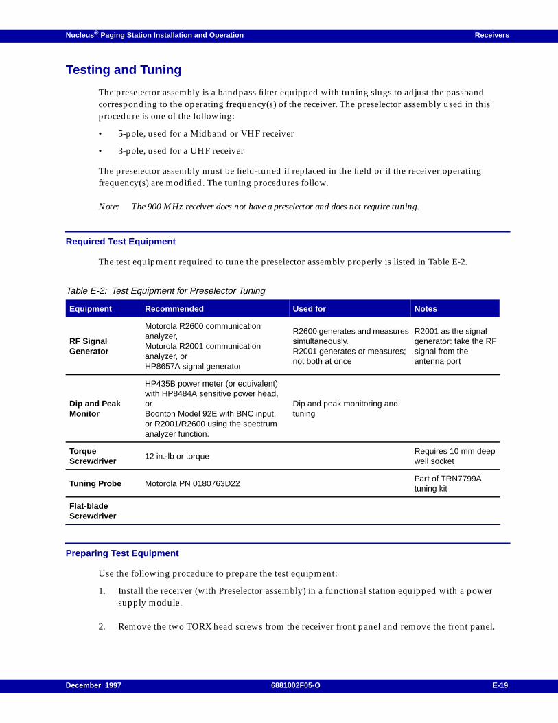
Nucleus ® Paging Station Installation and Operation Receivers
Testing and Tuning
The preselector assembly is a bandpass filter equipped with tuning slugs to adjust the passbandcorresponding to the operating frequency(s) of the receiver. The preselector assembly used in thisprocedure is one of the following:
• 5-pole, used for a Midband or VHF receiver
• 3-pole, used for a UHF receiver
The preselector assembly must be field-tuned if replaced in the field or if the receiver operatingfrequency(s) are modified. The tuning procedures follow.
Note: The 900 MHz receiver does not have a preselector and does not require tuning.
Required Test Equipment
The test equipment required to tune the preselector assembly properly is listed in Table E-2.
Preparing Test Equipment
Use the following procedure to prepare the test equipment:
1. Install the receiver (with Preselector assembly) in a functional station equipped with a powersupply module.
2. Remove the two TORX head screws from the receiver front panel and remove the front panel.
Table E-2: Test Equipment for Preselector Tuning
Equipment Recommended Used for Notes
RF SignalGenerator
Motorola R2600 communicationanalyzer,Motorola R2001 communicationanalyzer, orHP8657A signal generator
R2600 generates and measuressimultaneously.R2001 generates or measures;not both at once
R2001 as the signalgenerator: take the RFsignal from theantenna port
Dip and PeakMonitor
HP435B power meter (or equivalent)with HP8484A sensitive power head,orBoonton Model 92E with BNC input,or R2001/R2600 using the spectrumanalyzer function.
Dip and peak monitoring andtuning
TorqueScrewdriver
12 in.-lb or torqueRequires 10 mm deepwell socket
Tuning Probe Motorola PN 0180763D22Part of TRN7799Atuning kit
Flat-bladeScrewdriver
December 1997 6881002F05-O E-19
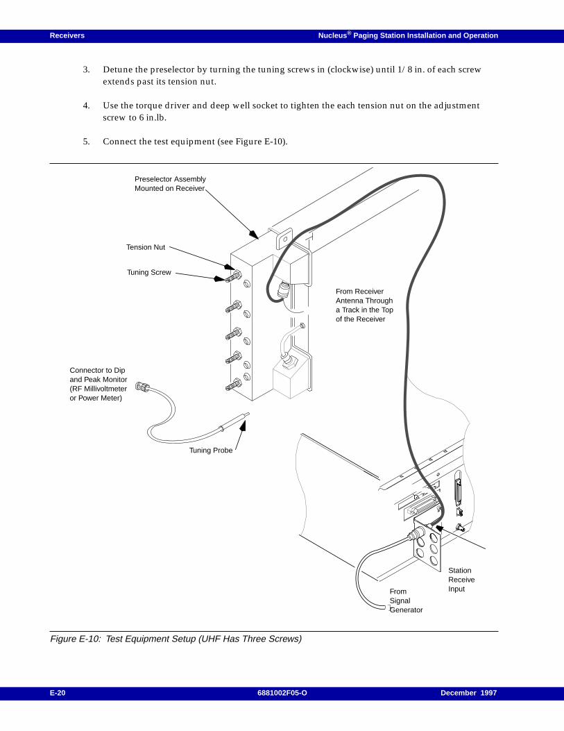
Receivers Nucleus ® Paging Station Installation and Operation
3. Detune the preselector by turning the tuning screws in (clockwise) until 1/8 in. of each screwextends past its tension nut.
4. Use the torque driver and deep well socket to tighten the each tension nut on the adjustmentscrew to 6 in.lb.
5. Connect the test equipment (see Figure E-10).
Figure E-10: Test Equipment Setup (UHF Has Three Screws)
Tension Nut
Tuning Screw
Preselector AssemblyMounted on Receiver
Connector to Dipand Peak Monitor(RF Millivoltmeteror Power Meter)
Tuning Probe
From ReceiverAntenna Througha Track in the Topof the Receiver
StationReceiveInputFrom
SignalGenerator
E-20 6881002F05-O December 1997
Nucleus ® Paging Station Installation and Operation Receivers
Proper Alignment Frequency–VHF and Midband
Note: Tuning for best SINAD response does not result in optimum tuning of the preselector assembly. Youmust use this field tuning procedure to obtain optimum preselector performance.
Use one of the following methods to calculate the alignment frequency to be generated by the signalgenerator.
Receivers with a Single Receive Frequency
Use the one of the following steps to calculate the appropriate alignment frequency:
1. Determine the receiver receive frequency (frx).
2. Calculate the alignment frequency (falign):
– Calculate the alignment frequency (falign) for a VHF 132–154 MHz receiver:- If 134 ≤ frx v 152 MHz, then falign = frx.- If frx < 134 MHz, then falign = 134 MHz.- If frx > 152 MHz, then falign = 152 MHz.
– Calculate the alignment frequency (falign) for a VHF 150–174 MHz receiver:- If 152 ≤ frx v 172 MHz, then falign = frx.- If frx < 152 MHz, then falign = 152 MHz.- If frx > 172 MHz, then falign = 172 MHz.
– Calculate the alignment frequency (falign) for a Midband 72–76 MHz receiver:- falign = frx.
Receivers with Multiple Receive Frequencies
Note: The receive frequency for each channel supported by the receiver.
1. Calculate a midpoint frequency:
fmid = (fhighest + flowest) ÷ 2
2. Using fmid in place of the receiver receive frequency (frx), perform the appropriate calculationabove.
Note: When tuning for peak or dip, turn the tuning screw 1/2 turn past the peak or dip to verify that you haveobtained a true peak or dip. Then turn the screw back to the location of the original peak or dip.
Tuning Procedure–VHF and Midband
Use the following procedure to tune the preselector:
1. Turn the station power supply ON (to provide the active 50 W termination).
2. Adjust the signal generator to the alignment frequency calculated previously. Set the level to+5 dBm.
3. Insert the tuning probe into cavity H2 and adjust tuning screw 1 for a PEAK.
December 1997 6881002F05-O E-21
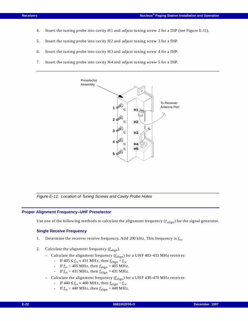
Receivers Nucleus ® Paging Station Installation and Operation
4. Insert the tuning probe into cavity H1 and adjust tuning screw 2 for a DIP (see Figure E-11).
5. Insert the tuning probe into cavity H2 and adjust tuning screw 3 for a DIP.
6. Insert the tuning probe into cavity H3 and adjust tuning screw 4 for a DIP.
7. Insert the tuning probe into cavity H4 and adjust tuning screw 5 for a DIP.
Figure E-11: Location of Tuning Screws and Cavity Probe Holes
Proper Alignment Frequency–UHF Preselector
Use one of the following methods to calculate the alignment frequency (ƒalign) for the signal generator.
Single Receive Frequency
1. Determine the receiver receive frequency. Add 200 kHz. This frequency is frx.
2. Calculate the alignment frequency (falign).
– Calculate the alignment frequency (falign) for a UHF 403–433 MHz receiver:- If 405 ≤ frx v 431 MHz, then falign = frx.- If frx < 405 MHz, then falign = 405 MHz.- If frx > 431 MHz, then falign = 431 MHz.
– Calculate the alignment frequency (falign) for a UHF 438–470 MHz receiver:- If 440 ≤ frx v 468 MHz, then falign = frx.- If frx < 440 MHz, then falign = 440 MHz.
PreselectorAssembly
H1
To ReceiverAntenna Port1
2
3
4
5
H2
H3
H4H5
E-22 6881002F05-O December 1997
Nucleus ® Paging Station Installation and Operation Receivers
- If frx > 468 MHz, then falign = 468 MHz.
– Calculate the alignment frequency (falign) for a UHF 470–496 MHz or 496–520 MHz receiver:- If 472 ≤ frx v 518 MHz, then falign = frx.- If frx < 472 MHz, then falign = 472 MHz.- If frx > 518 MHz, then falign = 518 MHz.
Multiple Receive Frequencies:
1. Note the receive frequency for each channel supported by the receiver.
2. Calculate a midpoint frequency:
fmid = (fhighest + flowest) ÷ 2
3. Using fmid in place of the receiver receive frequency, perform the appropriate calculation above.
Tuning Procedure–UHF Preselector
Use this procedure to tune the UHF preselector:
1. Turn the station power supply ON (to provide the active 50 W termination).
2. Adjust the signal generator to the alignment frequency calculated previously. Set the level to+5 dBm.
3. Insert a tuning probe into cavity U2 and adjust tuning screw 2 for a PEAK.
4. Tighten the tension nut on tuning screw 2 to at least 12 in.-lb. Fine tune tuning screw 2 for aPEAK.
5. Keep the tuning probe in cavity U2 and adjust tuning screw 3 for a DIP.
6. Tighten the tension nut on tuning screw 3 to at least 12 in.-lb. Fine tune tuning screw 2 for a DIP.
7. Insert the tuning probe into cavity U3. Decrease the output from the signal generator to -5 dBm.
8. Adjust tuning screw 4 for a DIP.
9. Tighten tension nut on tuning screw 4 to at least 12 in.-lb and fine tune tuning screw 4 for a DIP.
Proper Alignment Frequency–280 MHz Preselector
Use one of the following methods to calculate the alignment frequency (ƒalign) to be generated by thesignal generator.
Single Receive Frequency
1. Determine the receiver receive frequency. Add 200 kHz. This frequency is frx.
2. Calculate alignment frequency (ƒalign) for a UHF 276–288 MHz receiver:
December 1997 6881002F05-O E-23
Receivers Nucleus ® Paging Station Installation and Operation
If 278 £ ƒrx ≤286 MHz then ƒalign= ƒrx.
If ƒrx < 278 MHz then ƒalign= 278 MHz.
If ƒrx > 286 MHz then ƒalign = 286 MHz.
3. For receivers with multiple receive frequencies
a. Note the receive frequency for each channel supported by the receiver.
b. Calculate a midpoint frequency as follows:
ƒmid = (ƒhighest + ƒlowest) * (1/2)
c. Using ƒmid in place of the receiver frequency, perform Step 1 and Step 2 above.
Required Test Equipment–280 MHz Preselector
The following test equipment is required to properly tune the preselector assembly:
• RF signal generator
• Dip and peak monitor
• Torque driver capable of delivering 12 in.-lb of torque and 10 mm deep well socket
• Tuning probe—Motorola Part No. 0180763D22, part of TRN7799A tuning kit
• Flat-blade screwdriver
The preferred signal generator is a Motorola R2600 Communications Analyzer, R2001Communications Analyzer, or HP8657A signal generator (or equivalent).
The R2600 Communications Analyzer can both generate and measure simultaneously. The R2001 maybe used for either the generator or the monitor function, but not both simultaneously. When usingR2001 as the signal generator, take the RF signal from the antenna port.
The preferred monitor is HP435B Power Meter (or equivalent) with HP8484A sensitive power head,Boonton Model 92E with BNC input, or R2001/R2600 using the spectrum analyzer function.
Preparing Equipment–280 MHz Preselector
1. Install the receiver and Preselector assembly in a functional station cage with a power supplymodule.
2. Remove the two TORX head screws from the receiver front panel and remove the panel.
3. Detune the preselector. Turn tuning screws 3 and 4 clockwise until they no longer turn. Be carefulnot to apply more than 3 in.-lb of torque to prevent warping the preselector cover and housing.
4. Connect the test equipment (see Figure E-10).
Note: When tuning for peak or dip, turn the tuning screw 1/2 turn past the peak or dip to obtain a true peakor dip. Then turn the screw back to the location of the original peak or dip.
E-24 6881002F05-O December 1997
Nucleus ® Paging Station Installation and Operation Receivers
Tuning Procedure–280 MHz Preselector
Use the following procedure to tune the 280 MHz Preselector.
1. Remove the two TORX head screws from the receiver front panel and remove the panel.
2. Use the torque driver and deep well socket to loosen the three tension nuts on the adjustmentscrews.
3. Detune the preselector by turning each of the five tuning screws clockwise until they are fullyturned. Be careful not to apply more than 3 in.-lb of torque to prevent warping the preselectorcover and housing.
4. Turn the receiver power supply ON (to provide the active 50 Ohm termination).
5. Adjust the signal generator to the frequency ƒalign calculated above (with no modulation). Set theinput level to the receiver at +5 dBm.
6. Insert the tuning (RF) probe into cavity H1 and adjust the tuning screw 1 anti-clockwise for aPEAK.
Note: When tuning for peak or dip, turn the tuning screw 1/2 turn past the peak or dip to verify that you haveobtained a true peak or dip. Then turn the screw back to the location of the original peak or dip.
7. Tighten tension nut on tuning screw 1 to at least 12 in.-lb and fine tune tuning screw 1 for aPEAK.
8. Keep tuning probe in cavity H1 and adjust tuning screw 2 anti-clockwise for a DIP.
9. Tighten tension nut on tuning screw 2 to at least 12 in.-lb and fine tune tuning screw 2 for a DIP.
10. Insert tuning probe into cavity H2 and adjust tuning screw 3 anti-clockwise for a DIP.
11. Tighten tension nut on tuning screw 3 to at least 12 in.-lb and fine tune tuning screw 3 for a DIP.
12. Insert tuning probe into cavity H3 and adjust tuning screw 4 anti-clockwise for a DIP.
13. Tighten tension nut on tuning screw 4 to at least 12 in.-lb and fine tune tuning screw 4 for a DIP.
14. Insert tuning probe into cavity H4 and adjust tuning screw 5 anti-clockwise for a DIP.
15. Tighten tension nut on tuning screw 5 to at least 12 in.-lb and fine tune tuning screw 5 for a DIP.
December 1997 6881002F05-O E-25

Receivers Nucleus ® Paging Station Installation and Operation
E-26 6881002F05-O December 1997

Nucleus ® Paging Station Installation and Operation / Appendix F
GPS Antenna F
This appendix describes installing or repairing a Global Positioning System (GPS) antenna installed ata Nucleus paging station. This chapter contains the following information:
Installation, F-2Required Tools and Equipment, F-2Procedure, F-3
Repairing an Installed Antenna, F-5Disassembling the Antenna, F-5Connecting the Cable to the Antenna, F-6Attaching the Antenna to the Pipe Mast, F-7
Replacing a GPS Receiver Module, F-9
December 1997 6881002F05-O F-1
GPS Antenna Nucleus ® Paging Station Installation and Operation
Installation
This section describes installation procedures for a complete GPS antenna (Model No. RLN4394A).
Required Tools and Equipment
Required tools and materials include the following:
• TORX screwdriver set
• Torque wrench
• 10 mm wrenches
• Fiberglass or wooden ladder (if needed to put the antenna in place)
• One or more scissor clamps
F-2 6881002F05-O December 1997
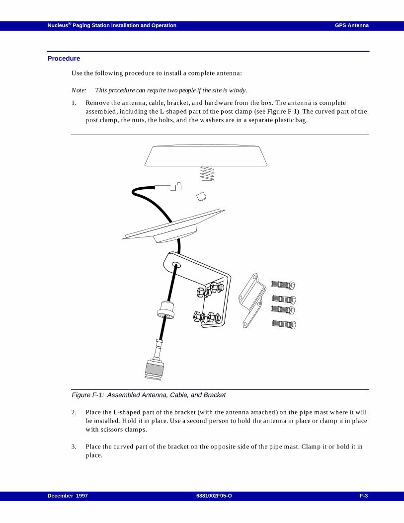
Nucleus ® Paging Station Installation and Operation GPS Antenna
Procedure
Use the following procedure to install a complete antenna:
Note: This procedure can require two people if the site is windy.
1. Remove the antenna, cable, bracket, and hardware from the box. The antenna is completeassembled, including the L-shaped part of the post clamp (see Figure F-1). The curved part of thepost clamp, the nuts, the bolts, and the washers are in a separate plastic bag.
Figure F-1: Assembled Antenna, Cable, and Bracket
2. Place the L-shaped part of the bracket (with the antenna attached) on the pipe mast where it willbe installed. Hold it in place. Use a second person to hold the antenna in place or clamp it in placewith scissors clamps.
3. Place the curved part of the bracket on the opposite side of the pipe mast. Clamp it or hold it inplace.
December 1997 6881002F05-O F-3

GPS Antenna Nucleus ® Paging Station Installation and Operation
4. Insert one bolt through one hole in each bracket. Place a washer on the bolt and tighten with anut. Use 10-mm wrenches.
5. Insert the other three bolts through the brackets. Tighten with washers and nuts.
6. Screw the large N-type male connector down over the N-type female connector on the carriercable.
7. Waterproof the area around the large N-type connection.
F-4 6881002F05-O December 1997
Nucleus ® Paging Station Installation and Operation GPS Antenna
Repairing an Installed Antenna
This section describes replacement of any part of the antenna.
The models for replacement parts are:
• RLN4388A–GPS antenna and rubber boot
• RLN4390A–mounting shroud, outer gasket and cable-retaining nut
• RLN4391A–post clamp, post bracket, nuts (4), lock washers (4) and bolts (4)
• RKN4395A–1 ft length cable with N-type connectors
This procedure includes:
• Disassembling the antenna to remove the defective part
• Connecting the cable to the antenna
• Attaching the antenna to the pipe mast
Disassembling the Antenna
Use this procedure to disassemble the antenna:
1. Take the antenna out of operation.
2. Disconnect the N-type base connector from the antenna cable.
3. Hold the antenna firmly. Remove four nuts, bolts, and washers from the curved bracket and theL-shaped bracket.
4. Remove the antenna from the pipe mast.
5. Unscrew the cable retaining nut. Allow the bracket to slide down the cable to the large N-typeconnector.
6. Hold the mounting shroud by its edges. Pull the mounting shroud away from the antenna. Allowthe mounting shroud to slide down the cable.
7. Gently pull the cable out of the threaded stem of the antenna.
8. Remove the rubber boot from the small connector on the antenna.
9. Use a small straight-blade screwdriver to remove the small connector from the antenna.
10. Pull the cable out of the assembly.
11. Replace the faulty or broken parts of the antenna.
12. Continue with the reassembly instructions that follow.
December 1997 6881002F05-O F-5
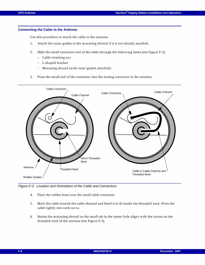
GPS Antenna Nucleus ® Paging Station Installation and Operation
Connecting the Cable to the Antenna
Use this procedure to attach the cable to the antenna:
1. Attach the outer gasket to the mounting shroud if it is not already attached.
2. Slide the small connector end of the cable through the following items (see Figure F-2):
– Cable retaining nut
– L-shaped bracket
– Mounting shroud (with outer gasket attached)
3. Press the small end of the connector into the mating connector in the antenna.
Figure F-2: Location and Orientation of the Cable and Connectors
4. Place the rubber boot over the small cable connector.
5. Bend the cable around the cable channel and bend it to fit inside the threaded neck. Press thecable tightly into each curve.
6. Rotate the mounting shroud so the small tab in the center hole aligns with the cutout on thethreaded neck of the antenna (see Figure F-3).
Antenna
Rubber Gasket
Cable Connector
Cable Channel
Threaded NeckCable in Cable Channel andThreaded Neck
Cable ChannelCable Connector
Slot in ThreadedNeck
F-6 6881002F05-O December 1997
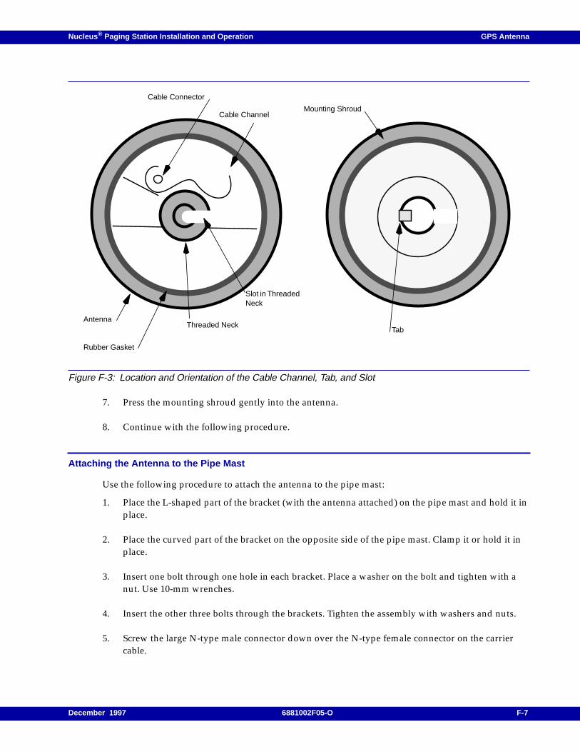
Nucleus ® Paging Station Installation and Operation GPS Antenna
Figure F-3: Location and Orientation of the Cable Channel, Tab, and Slot
7. Press the mounting shroud gently into the antenna.
8. Continue with the following procedure.
Attaching the Antenna to the Pipe Mast
Use the following procedure to attach the antenna to the pipe mast:
1. Place the L-shaped part of the bracket (with the antenna attached) on the pipe mast and hold it inplace.
2. Place the curved part of the bracket on the opposite side of the pipe mast. Clamp it or hold it inplace.
3. Insert one bolt through one hole in each bracket. Place a washer on the bolt and tighten with anut. Use 10-mm wrenches.
4. Insert the other three bolts through the brackets. Tighten the assembly with washers and nuts.
5. Screw the large N-type male connector down over the N-type female connector on the carriercable.
Antenna
Rubber Gasket
Cable Connector
Cable Channel
Threaded NeckTab
Mounting Shroud
Slot in ThreadedNeck
December 1997 6881002F05-O F-7

GPS Antenna Nucleus ® Paging Station Installation and Operation
6. Waterproof the area around the large N-type connection.
7. Place the antenna back in operation.
F-8 6881002F05-O December 1997
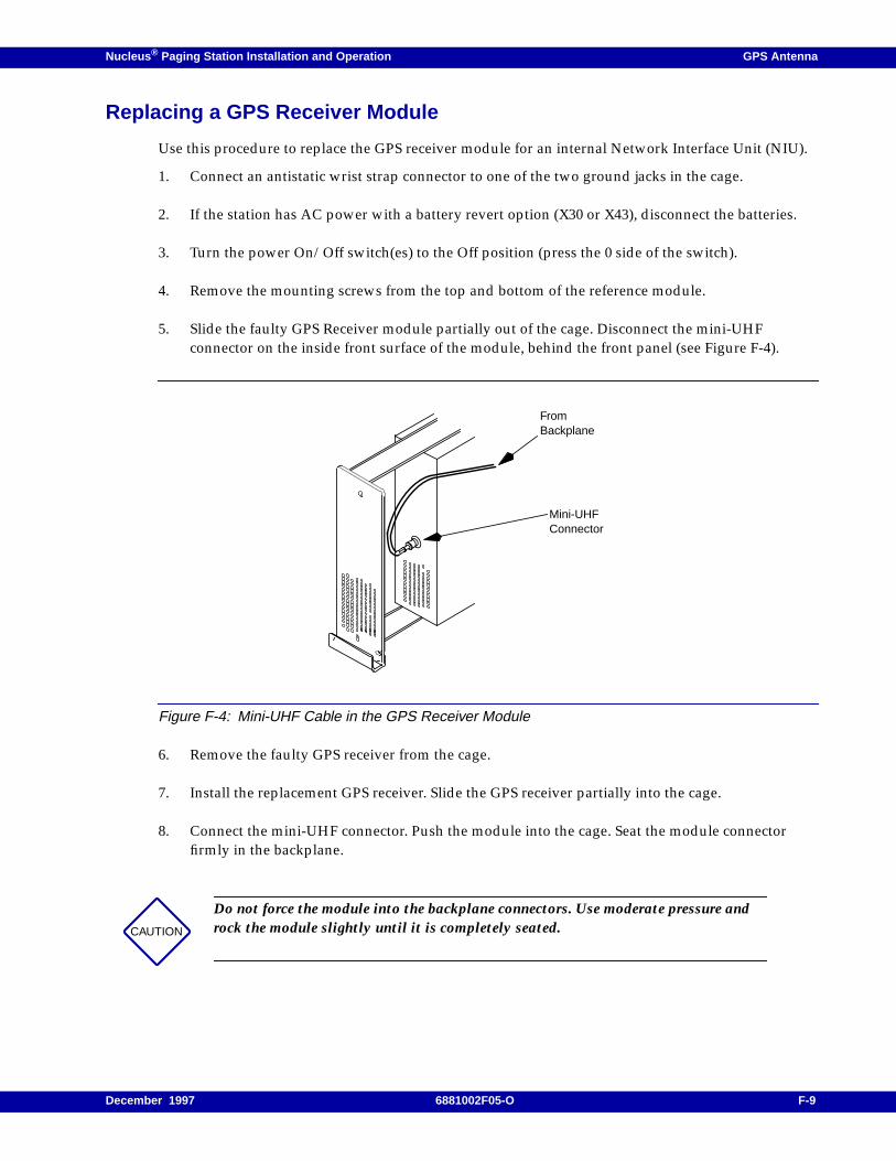
Nucleus ® Paging Station Installation and Operation GPS Antenna
Replacing a GPS Receiver Module
Use this procedure to replace the GPS receiver module for an internal Network Interface Unit (NIU).
1. Connect an antistatic wrist strap connector to one of the two ground jacks in the cage.
2. If the station has AC power with a battery revert option (X30 or X43), disconnect the batteries.
3. Turn the power On/Off switch(es) to the Off position (press the 0 side of the switch).
4. Remove the mounting screws from the top and bottom of the reference module.
5. Slide the faulty GPS Receiver module partially out of the cage. Disconnect the mini-UHFconnector on the inside front surface of the module, behind the front panel (see Figure F-4).
Figure F-4: Mini-UHF Cable in the GPS Receiver Module
6. Remove the faulty GPS receiver from the cage.
7. Install the replacement GPS receiver. Slide the GPS receiver partially into the cage.
8. Connect the mini-UHF connector. Push the module into the cage. Seat the module connectorfirmly in the backplane.
CAUTION
Do not force the module into the backplane connectors. Use moderate pressure androck the module slightly until it is completely seated.
FromBackplane
Mini-UHFConnector
December 1997 6881002F05-O F-9

GPS Antenna Nucleus ® Paging Station Installation and Operation
9. Replace the mounting screws removed in Step 4.
10. If the Nucleus paging station has AC power with a battery revert option (X30 or X43) turn thepower On-Off switch to On (press the side of the switch). Then reconnect the battery.
11. Disconnect the antistatic wrist strap.
F-10 6881002F05-O December 1997