Embed Size (px)
Citation preview
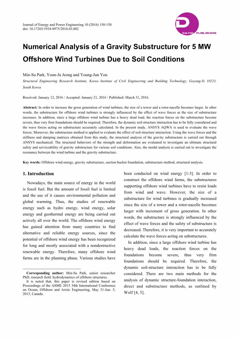
Journal of Energy and Power Engineering 10 (2016) 150-158 doi: 10.17265/1934-8975/2016.03.002
Numerical Analysis of a Gravity Substructure for 5 MW
Offshore Wind Turbines Due to Soil Conditions
Min-Su Park, Youn-Ju Jeong and Young-Jun You
Structural Engineering Research Institute, Korea Institute of Civil Engineering and Building Technology, Goyang-Si 10223,
South Korea
Received: January 12, 2016 / Accepted: January 21, 2016 / Published: March 31, 2016. Abstract: In order to increase the gross generation of wind turbines, the size of a tower and a rotor-nacelle becomes larger. In other words, the substructure for offshore wind turbines is strongly influenced by the effect of wave forces as the size of substructure increases. In addition, since a large offshore wind turbine has a heavy dead load, the reaction forces on the substructure become severe, thus very firm foundations should be required. Therefore, the dynamic soil-structure interaction has to be fully considered and the wave forces acting on substructure accurately calculated. In the present study, ANSYS AQWA is used to evaluate the wave forces. Moreover, the substructure method is applied to evaluate the effect of soil-structure interaction. Using the wave forces and the stiffness and damping matrices obtained from this study, the structural analysis of the gravity substructure is carried out through ANSYS mechanical. The structural behaviors of the strength and deformation are evaluated to investigate an ultimate structural safety and serviceability of gravity substructure for various soil conditions. Also, the modal analysis is carried out to investigate the resonance between the wind turbine and the gravity substructure.
Key words: Offshore wind energy, gravity substructure, suction bucket foundation, substructure method, structural analysis.
1. Introduction
Nowadays, the main source of energy in the world
is fossil fuel. But the amount of fossil fuel is limited
and the use of it causes environmental pollution and
global warming. Thus, the studies of renewable
energy such as hydro energy, wind energy, solar
energy and geothermal energy are being carried out
actively all over the world. The offshore wind energy
has gained attention from many countries to find
alternative and reliable energy sources, since the
potential of offshore wind energy has been recognized
for long and mostly associated with a nondestructive
renewable energy. Therefore, many offshore wind
farms are in the planning phase. Various studies have
Corresponding author: Min-Su Park, senior researcher
PhD, research field: hydrodynamics of offshore structures. It is noted that, this paper is revised edition based on
Proceedings of the ASME 2015 34th International Conference on Ocean, Offshore and Arctic Engineering, May 31-Jun. 5, 2015, Canada.
been conducted on wind energy [1-3]. In order to
construct the offshore wind farms, the substructures
supporting offshore wind turbines have to resist loads
from wind and wave. However, the size of a
substructure for wind turbines is gradually increased
since the size of a tower and a rotor-nacelle becomes
larger with increment of gross generation. In other
words, the substructure is strongly influenced by the
effect of wave forces and the safety of substructure is
decreased. Therefore, it is very important to accurately
calculate the wave forces acting on substructures.
In addition, since a large offshore wind turbine has
heavy dead loads, the reaction forces on the
foundations become severe, thus very firm
foundations should be required. Therefore, the
dynamic soil-structure interaction has to be fully
considered. There are two main methods for the
analysis of dynamic structure-foundation interaction,
direct and substructure methods, as outlined by
Wolf [4, 5].
D DAVID PUBLISHING
Numerical Analysis of a Gravity Substructure for 5 MW Offshore Wind Turbines Due to Soil Conditions
151
In the present study, ANSYS AQWA is used to
evaluate the wave forces acting on the gravity
substructure for 5 MW offshore wind turbine, since
Morison equation cannot accurately calculate the
wave forces in case of the large substructure compared
to a wave length. The substructure is significantly
influenced by the wave steepness and wave slamming
effects but they are not considered in the present study,
because the wave breaking is not occurred for the
design environmental wave conditions. The wave
forces and wave run up on the substructure are
presented for various wave conditions. Moreover, the
substructure method is applied to evaluate the effect of
soil-structure interaction with impedance coefficients
as damping and stiffness matrices. Using the wave
forces and the stiffness and damping matrices
obtained from this study, the structural analysis of the
gravity substructure is carried out through ANSYS
mechanical. The structural behaviors of the strength
and deformation are evaluated to investigate an
ultimate structural safety and serviceability of gravity
substructure for various soil conditions. The first few
natural frequencies of substructure are heavily
influenced by the wind turbine. Therefore, the first
natural frequency of substructure is to be within the
soft-stiff range in between the 1 P and 3 P frequency
ranges. The rotor frequency (1 P) range lies between
0.115 Hz and 0.202 Hz, and the blade passing
frequency (3 P) range lies between 0.35 Hz and 0.61 Hz.
A safety margin of 10% on the maximum and
minimum rotor speed is adopted, which means that,
the allowable frequency is between 0.222 Hz and
0.31 Hz [6]. Therefore, the modal analysis is carried
out to investigate the resonance between the wind
turbine and the gravity substructure. It is found that,
the suggested gravity substructure can be an effective
substructure for 5 MW offshore wind turbines.
2. Formulation
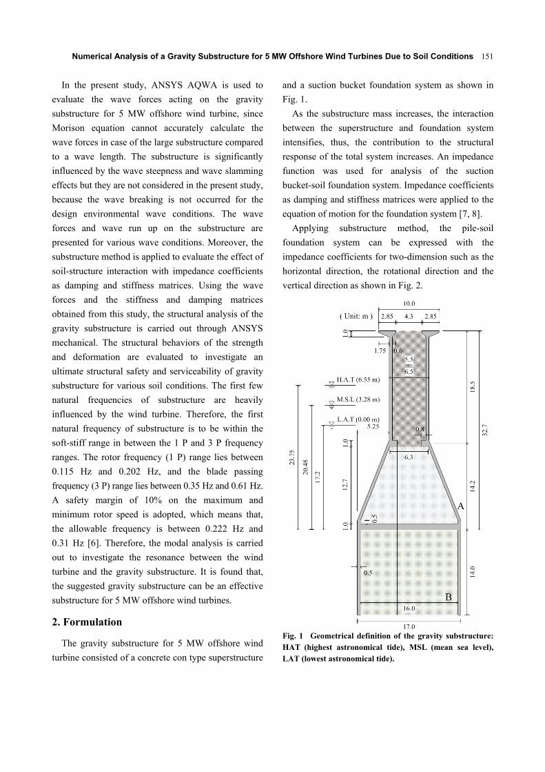
The gravity substructure for 5 MW offshore wind
turbine consisted of a concrete con type superstructure
and a suction bucket foundation system as shown in
Fig. 1.
As the substructure mass increases, the interaction
between the superstructure and foundation system
intensifies, thus, the contribution to the structural
response of the total system increases. An impedance
function was used for analysis of the suction
bucket-soil foundation system. Impedance coefficients
as damping and stiffness matrices were applied to the
equation of motion for the foundation system [7, 8].
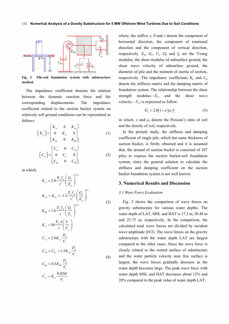
Applying substructure method, the pile-soil
foundation system can be expressed with the
impedance coefficients for two-dimension such as the
horizontal direction, the rotational direction and the
vertical direction as shown in Fig. 2.
Fig. 1 Geometrical definition of the gravity substructure: HAT (highest astronomical tide), MSL (mean sea level), LAT (lowest astronomical tide).
Numerical Analysis of a Gravity Substructure for 5 MW Offshore Wind Turbines Due to Soil Conditions
152
Fig. 2 Pile-soil foundation system with substructure method.
The impedance coefficient denotes the relation
between the dynamic reaction force and the
corresponding displacements. The impedance
coefficient related to the suction bucket system on
relatively soft ground conditions can be represented as
follows:
0
0 0
0
xx x
p zz
x
K K
K K
K K
(1)
0
0 0
0
xx x
p zz
x
C C
C C
C C
(2)
in which: 0.75
3
0.5
2
0.25
2.0
-1.2
1.6
50
p sxx
p
p sx x
p
p s
p
p szz
p
p
p
p
E I GK
r E
E IK K
r E
E IK
r E
E A VK
l V
G
G
(3)
2.0
1.5
0.5
0.026
p
xx xx
s
p
x x x
s
p
s
zz zz
s
DC K
V
DC C K
V
DC K
V
lC K
V
(4)
where, the suffixs x, θ and z denote the component of
horizontal direction, the component of rotational
direction and the component of vertical direction,
respectively. Ep, Gs, Vs, Dp and Ip are the Young
modulus, the shear modulus of subsurface ground, the
shear wave velocity of subsurface ground, the
diameter of pile and the moment of inertia of section,
respectively. The impedance coefficients Kp and Cp
denote the stiffness matrix and the damping matrix of
foundation system. The relationship between the shear
strength modulus—Es, and the shear wave
velocity—Vs, is expressed as follow:
2.0 1s s sVG (5)
in which, υ and ρs denote the Poisson’s ratio of soil
and the density of soil, respectively.
In the present study, the stiffness and damping
coefficient of single pile, which has same thickness of
suction bucket, is firstly obtained and it is assumed
that, the around of suction bucket is consisted of 107
piles to express the suction bucket-soil foundation
system, since the general solution to calculate the
stiffness and damping coefficient on the suction
bucket foundation system is not well known.
3. Numerical Results and Discussion
3.1 Wave Force Evaluation
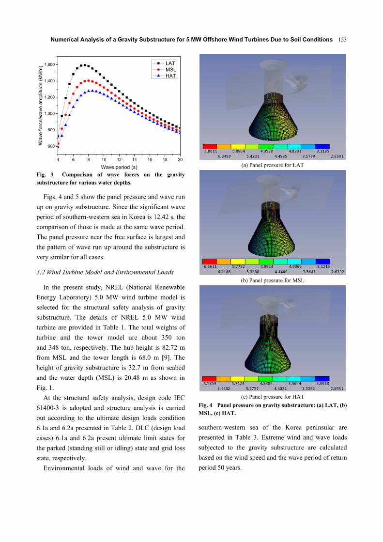
Fig. 3 shows the comparison of wave forces on
gravity substructure for various water depths. The
water depth of LAT, MSL and HAT is 17.2 m, 20.48 m
and 23.75 m, respectively. In the comparison, the
calculated total wave forces are divided by incident
wave amplitude (H/2). The wave forces on the gravity
substructure with the water depth LAT are largest
compared to the other cases. Since the wave force is
closely related to the wetted surface of substructure
and the water particle velocity near free surface is
largest, the wave forces gradually decrease as the
water depth becomes large. The peak wave force with
water depth MSL and HAT decreases about 12% and
20% compared to the peak value of water depth LAT.
Numerical Analysis of a Gravity Substructure for 5 MW Offshore Wind Turbines Due to Soil Conditions
153
4 6 8 10 12 14 16 18 20
600
800
1,000
1,200
1,400
1,600
Wave
for
ce/w
ave
am
plitu
de (
kN/m
)
Wave period (s)
LAT MSL HAT
.
Fig. 3 Comparison of wave forces on the gravity substructure for various water depths.
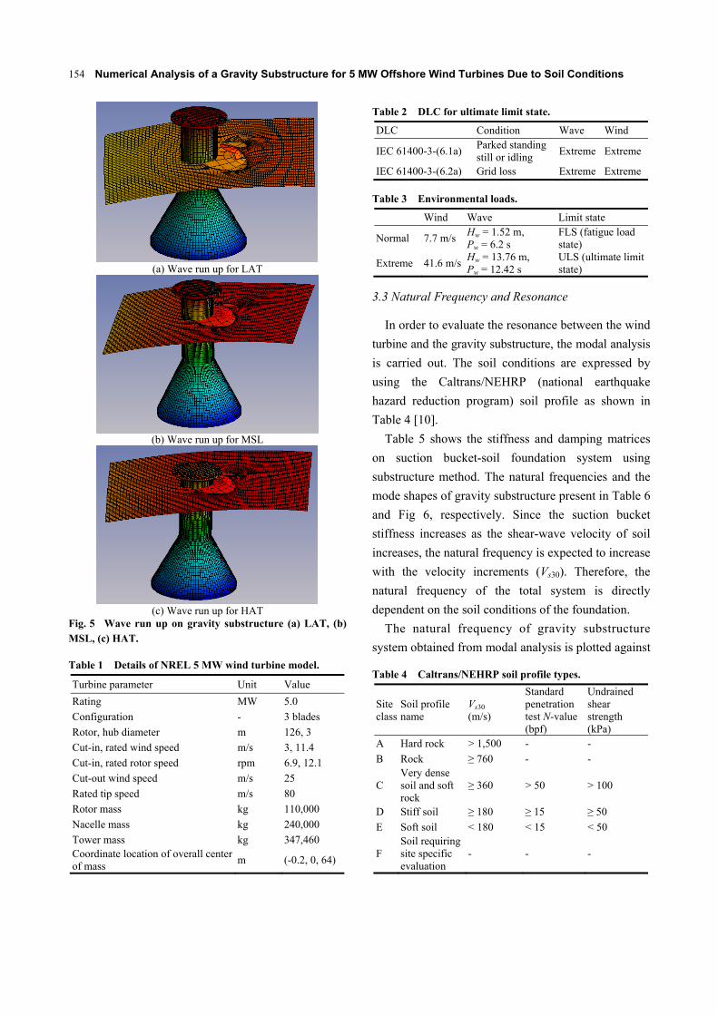
Figs. 4 and 5 show the panel pressure and wave run
up on gravity substructure. Since the significant wave
period of southern-western sea in Korea is 12.42 s, the
comparison of those is made at the same wave period.
The panel pressure near the free surface is largest and
the pattern of wave run up around the substructure is
very similar for all cases.
3.2 Wind Turbine Model and Environmental Loads
In the present study, NREL (National Renewable
Energy Laboratory) 5.0 MW wind turbine model is
selected for the structural safety analysis of gravity
substructure. The details of NREL 5.0 MW wind
turbine are provided in Table 1. The total weights of
turbine and the tower model are about 350 ton
and 348 ton, respectively. The hub height is 82.72 m
from MSL and the tower length is 68.0 m [9]. The
height of gravity substructure is 32.7 m from seabed
and the water depth (MSL) is 20.48 m as shown in
Fig. 1.
At the structural safety analysis, design code IEC
61400-3 is adopted and structure analysis is carried
out according to the ultimate design loads condition
6.1a and 6.2a presented in Table 2. DLC (design load
cases) 6.1a and 6.2a present ultimate limit states for
the parked (standing still or idling) state and grid loss
state, respectively.
Environmental loads of wind and wave for the
(a) Panel pressure for LAT
(b) Panel pressure for MSL
(c) Panel pressure for HAT
Fig. 4 Panel pressure on gravity substructure: (a) LAT, (b) MSL, (c) HAT.
southern-western sea of the Korea peninsular are
presented in Table 3. Extreme wind and wave loads
subjected to the gravity substructure are calculated
based on the wind speed and the wave period of return
period 50 years.
Numerical Analysis of a Gravity Substructure for 5 MW Offshore Wind Turbines Due to Soil Conditions
154
(a) Wave run up for LAT
(b) Wave run up for MSL
(c) Wave run up for HAT
Fig. 5 Wave run up on gravity substructure (a) LAT, (b) MSL, (c) HAT.
Table 1 Details of NREL 5 MW wind turbine model.
Turbine parameter Unit Value
Rating MW 5.0
Configuration - 3 blades
Rotor, hub diameter m 126, 3
Cut-in, rated wind speed m/s 3, 11.4
Cut-in, rated rotor speed rpm 6.9, 12.1
Cut-out wind speed m/s 25
Rated tip speed m/s 80
Rotor mass kg 110,000
Nacelle mass kg 240,000
Tower mass kg 347,460 Coordinate location of overall center of mass
m (-0.2, 0, 64)
Table 2 DLC for ultimate limit state.
DLC Condition Wave Wind
IEC 61400-3-(6.1a) Parked standing still or idling
Extreme Extreme
IEC 61400-3-(6.2a) Grid loss Extreme Extreme
Table 3 Environmental loads.
Wind Wave Limit state
Normal 7.7 m/sHw = 1.52 m, Pw = 6.2 s
FLS (fatigue load state)
Extreme 41.6 m/sHw = 13.76 m, Pw = 12.42 s
ULS (ultimate limit state)
3.3 Natural Frequency and Resonance
In order to evaluate the resonance between the wind
turbine and the gravity substructure, the modal analysis
is carried out. The soil conditions are expressed by
using the Caltrans/NEHRP (national earthquake
hazard reduction program) soil profile as shown in
Table 4 [10].
Table 5 shows the stiffness and damping matrices
on suction bucket-soil foundation system using
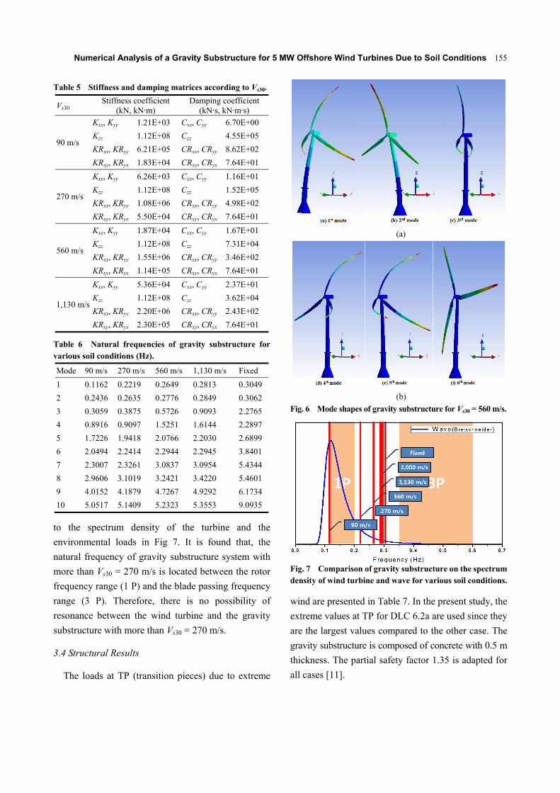
substructure method. The natural frequencies and the
mode shapes of gravity substructure present in Table 6
and Fig 6, respectively. Since the suction bucket
stiffness increases as the shear-wave velocity of soil
increases, the natural frequency is expected to increase
with the velocity increments (Vs30). Therefore, the
natural frequency of the total system is directly
dependent on the soil conditions of the foundation.
The natural frequency of gravity substructure
system obtained from modal analysis is plotted against
Table 4 Caltrans/NEHRP soil profile types.
Site class
Soil profile name
Vs30 (m/s)
Standard penetration test N-value (bpf)
Undrained shear strength (kPa)
A Hard rock > 1,500 - -
B Rock ≥ 760 - -
C Very dense soil and soft rock
≥ 360 > 50 > 100
D Stiff soil ≥ 180 ≥ 15 ≥ 50
E Soft soil < 180 < 15 < 50
F Soil requiring site specific evaluation
- - -
Numerical Analysis of a Gravity Substructure for 5 MW Offshore Wind Turbines Due to Soil Conditions
155
Table 5 Stiffness and damping matrices according to Vs30.
Vs30 Stiffness coefficient
(kN, kN·m) Damping coefficient
(kN·s, kN·m·s)
90 m/s
Kxx, Kyy 1.21E+03 Cxx, Cyy 6.70E+00
Kzz 1.12E+08 Czz 4.55E+05
KRxx, KRyy 6.21E+05 CRxx, CRyy 8.62E+02
KRxy, KRyx 1.83E+04 CRxy, CRyx 7.64E+01
270 m/s
Kxx, Kyy 6.26E+03 Cxx, Cyy 1.16E+01
Kzz 1.12E+08 Czz 1.52E+05
KRxx, KRyy 1.08E+06 CRxx, CRyy 4.98E+02
KRxy, KRyx 5.50E+04 CRxy, CRyx 7.64E+01
560 m/s
Kxx, Kyy 1.87E+04 Cxx, Cyy 1.67E+01
Kzz 1.12E+08 Czz 7.31E+04
KRxx, KRyy 1.55E+06 CRxx, CRyy 3.46E+02
KRxy, KRyx 1.14E+05 CRxy, CRyx 7.64E+01
1,130 m/s
Kxx, Kyy 5.36E+04 Cxx, Cyy 2.37E+01
Kzz 1.12E+08 Czz 3.62E+04
KRxx, KRyy 2.20E+06 CRxx, CRyy 2.43E+02
KRxy, KRyx 2.30E+05 CRxy, CRyx 7.64E+01
Table 6 Natural frequencies of gravity substructure for various soil conditions (Hz).
Mode 90 m/s 270 m/s 560 m/s 1,130 m/s Fixed
1 0.1162 0.2219 0.2649 0.2813 0.3049
2 0.2436 0.2635 0.2776 0.2849 0.3062
3 0.3059 0.3875 0.5726 0.9093 2.2765
4 0.8916 0.9097 1.5251 1.6144 2.2897
5 1.7226 1.9418 2.0766 2.2030 2.6899
6 2.0494 2.2414 2.2944 2.2945 3.8401
7 2.3007 2.3261 3.0837 3.0954 5.4344
8 2.9606 3.1019 3.2421 3.4220 5.4601
9 4.0152 4.1879 4.7267 4.9292 6.1734
10 5.0517 5.1409 5.2323 5.3553 9.0935
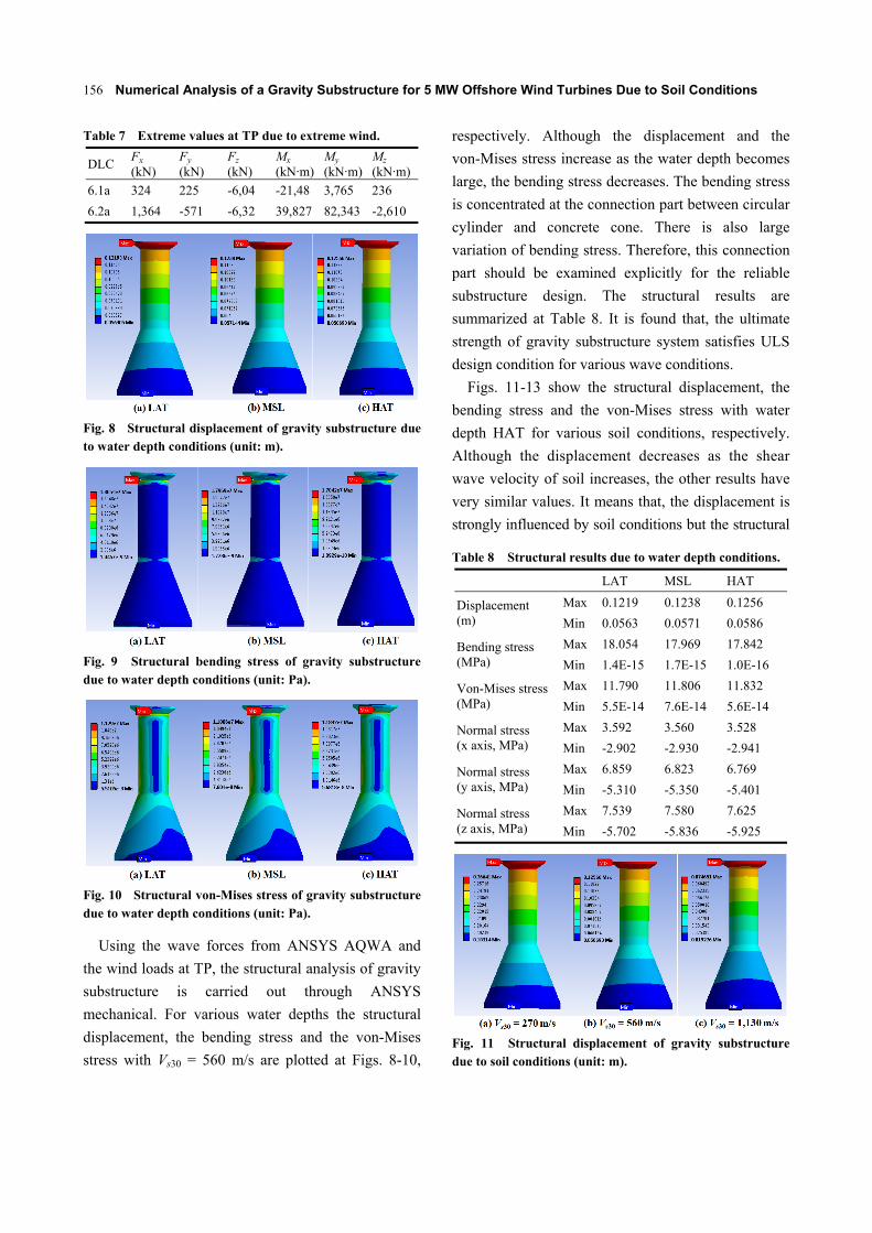
to the spectrum density of the turbine and the
environmental loads in Fig 7. It is found that, the
natural frequency of gravity substructure system with
more than Vs30 = 270 m/s is located between the rotor
frequency range (1 P) and the blade passing frequency
range (3 P). Therefore, there is no possibility of
resonance between the wind turbine and the gravity
substructure with more than Vs30 = 270 m/s.
3.4 Structural Results
The loads at TP (transition pieces) due to extreme
(a)
(b)
Fig. 6 Mode shapes of gravity substructure for Vs30 = 560 m/s.
Fig. 7 Comparison of gravity substructure on the spectrum density of wind turbine and wave for various soil conditions.
wind are presented in Table 7. In the present study, the
extreme values at TP for DLC 6.2a are used since they
are the largest values compared to the other case. The
gravity substructure is composed of concrete with 0.5 m
thickness. The partial safety factor 1.35 is adapted for
all cases [11].
Numerical Analysis of a Gravity Substructure for 5 MW Offshore Wind Turbines Due to Soil Conditions
156
Table 7 Extreme values at TP due to extreme wind.
DLC Fx (kN)
Fy (kN)
Fz (kN)
Mx (kN·m)
My (kN·m)
Mz (kN·m)
6.1a 324 225 -6,04 -21,48 3,765 236
6.2a 1,364 -571 -6,32 39,827 82,343 -2,610
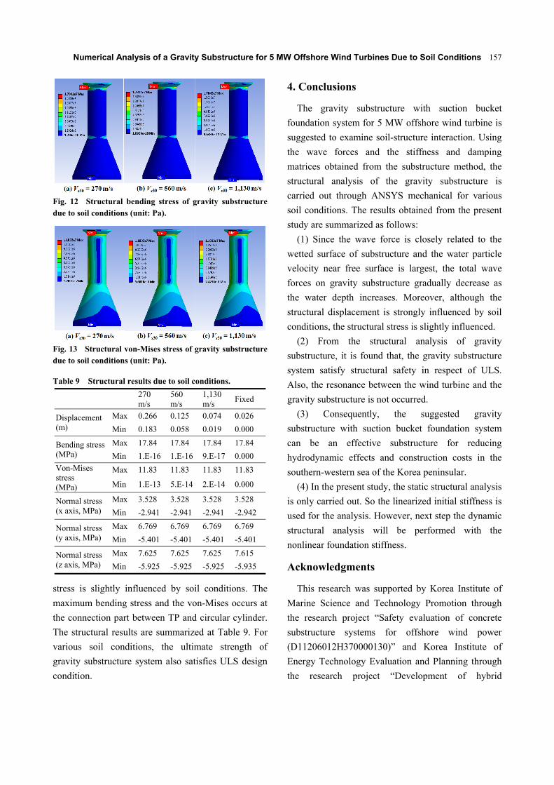
Fig. 8 Structural displacement of gravity substructure due to water depth conditions (unit: m).
Fig. 9 Structural bending stress of gravity substructure due to water depth conditions (unit: Pa).
Fig. 10 Structural von-Mises stress of gravity substructure due to water depth conditions (unit: Pa).
Using the wave forces from ANSYS AQWA and
the wind loads at TP, the structural analysis of gravity
substructure is carried out through ANSYS
mechanical. For various water depths the structural
displacement, the bending stress and the von-Mises
stress with Vs30 = 560 m/s are plotted at Figs. 8-10,
respectively. Although the displacement and the
von-Mises stress increase as the water depth becomes
large, the bending stress decreases. The bending stress
is concentrated at the connection part between circular
cylinder and concrete cone. There is also large
variation of bending stress. Therefore, this connection
part should be examined explicitly for the reliable
substructure design. The structural results are
summarized at Table 8. It is found that, the ultimate
strength of gravity substructure system satisfies ULS
design condition for various wave conditions.
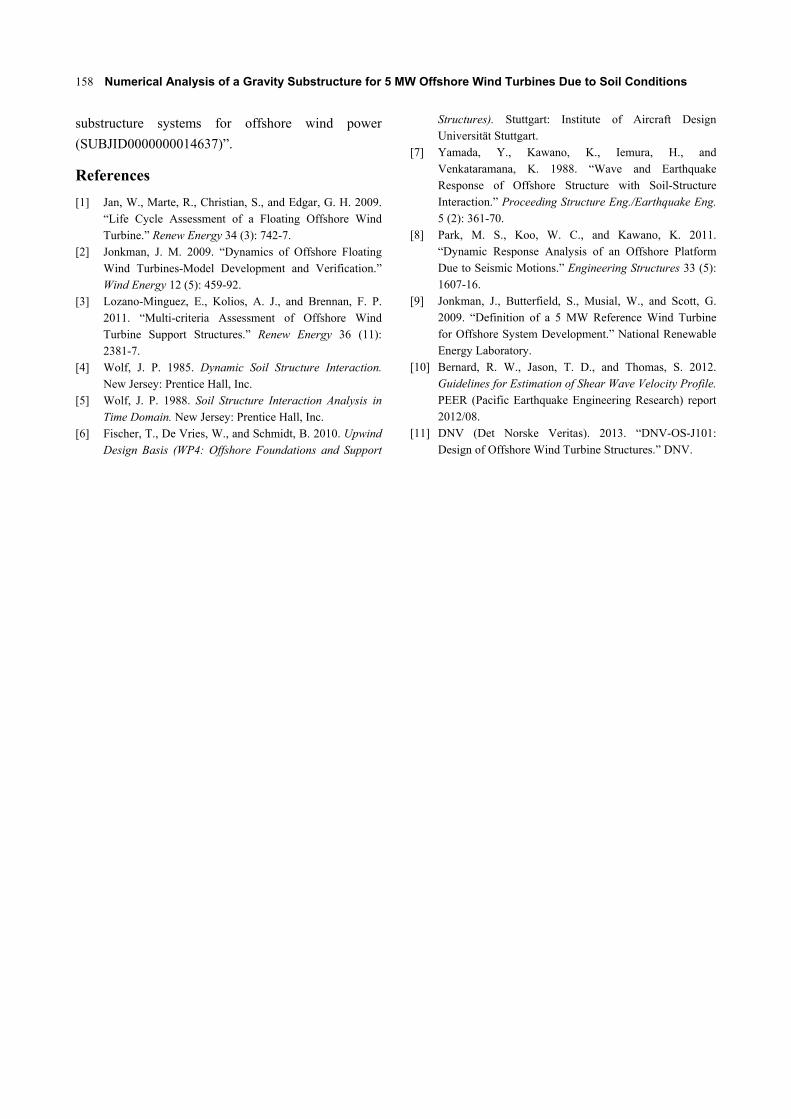
Figs. 11-13 show the structural displacement, the
bending stress and the von-Mises stress with water
depth HAT for various soil conditions, respectively.
Although the displacement decreases as the shear
wave velocity of soil increases, the other results have
very similar values. It means that, the displacement is
strongly influenced by soil conditions but the structural
Table 8 Structural results due to water depth conditions.
LAT MSL HAT
Displacement (m)
Max 0.1219 0.1238 0.1256
Min 0.0563 0.0571 0.0586
Bending stress (MPa)
Max 18.054 17.969 17.842
Min 1.4E-15 1.7E-15 1.0E-16
Von-Mises stress(MPa)
Max 11.790 11.806 11.832
Min 5.5E-14 7.6E-14 5.6E-14
Normal stress (x axis, MPa)
Max 3.592 3.560 3.528
Min -2.902 -2.930 -2.941
Normal stress (y axis, MPa)
Max 6.859 6.823 6.769
Min -5.310 -5.350 -5.401
Normal stress (z axis, MPa)
Max 7.539 7.580 7.625
Min -5.702 -5.836 -5.925
Fig. 11 Structural displacement of gravity substructure due to soil conditions (unit: m).
Numerical Analysis of a Gravity Substructure for 5 MW Offshore Wind Turbines Due to Soil Conditions
157
Fig. 12 Structural bending stress of gravity substructure due to soil conditions (unit: Pa).
Fig. 13 Structural von-Mises stress of gravity substructure due to soil conditions (unit: Pa).
Table 9 Structural results due to soil conditions.
270 m/s
560 m/s
1,130 m/s
Fixed
Displacement (m)
Max 0.266 0.125 0.074 0.026
Min 0.183 0.058 0.019 0.000
Bending stress (MPa)
Max 17.84 17.84 17.84 17.84
Min 1.E-16 1.E-16 9.E-17 0.000
Von-Mises stress (MPa)
Max 11.83 11.83 11.83 11.83
Min 1.E-13 5.E-14 2.E-14 0.000
Normal stress (x axis, MPa)
Max 3.528 3.528 3.528 3.528
Min -2.941 -2.941 -2.941 -2.942
Normal stress (y axis, MPa)
Max 6.769 6.769 6.769 6.769
Min -5.401 -5.401 -5.401 -5.401
Normal stress (z axis, MPa)
Max 7.625 7.625 7.625 7.615
Min -5.925 -5.925 -5.925 -5.935
stress is slightly influenced by soil conditions. The
maximum bending stress and the von-Mises occurs at
the connection part between TP and circular cylinder.
The structural results are summarized at Table 9. For
various soil conditions, the ultimate strength of
gravity substructure system also satisfies ULS design
condition.
4. Conclusions
The gravity substructure with suction bucket
foundation system for 5 MW offshore wind turbine is
suggested to examine soil-structure interaction. Using
the wave forces and the stiffness and damping
matrices obtained from the substructure method, the
structural analysis of the gravity substructure is
carried out through ANSYS mechanical for various
soil conditions. The results obtained from the present
study are summarized as follows:
(1) Since the wave force is closely related to the
wetted surface of substructure and the water particle
velocity near free surface is largest, the total wave
forces on gravity substructure gradually decrease as
the water depth increases. Moreover, although the
structural displacement is strongly influenced by soil
conditions, the structural stress is slightly influenced.
(2) From the structural analysis of gravity
substructure, it is found that, the gravity substructure
system satisfy structural safety in respect of ULS.
Also, the resonance between the wind turbine and the
gravity substructure is not occurred.
(3) Consequently, the suggested gravity
substructure with suction bucket foundation system
can be an effective substructure for reducing
hydrodynamic effects and construction costs in the
southern-western sea of the Korea peninsular.
(4) In the present study, the static structural analysis
is only carried out. So the linearized initial stiffness is
used for the analysis. However, next step the dynamic
structural analysis will be performed with the
nonlinear foundation stiffness.
Acknowledgments
This research was supported by Korea Institute of
Marine Science and Technology Promotion through
the research project “Safety evaluation of concrete
substructure systems for offshore wind power
(D11206012H370000130)” and Korea Institute of
Energy Technology Evaluation and Planning through
the research project “Development of hybrid
Numerical Analysis of a Gravity Substructure for 5 MW Offshore Wind Turbines Due to Soil Conditions
158
substructure systems for offshore wind power
(SUBJID0000000014637)”.
References
[1] Jan, W., Marte, R., Christian, S., and Edgar, G. H. 2009. “Life Cycle Assessment of a Floating Offshore Wind Turbine.” Renew Energy 34 (3): 742-7.
[2] Jonkman, J. M. 2009. “Dynamics of Offshore Floating Wind Turbines-Model Development and Verification.” Wind Energy 12 (5): 459-92.
[3] Lozano-Minguez, E., Kolios, A. J., and Brennan, F. P. 2011. “Multi-criteria Assessment of Offshore Wind Turbine Support Structures.” Renew Energy 36 (11): 2381-7.
[4] Wolf, J. P. 1985. Dynamic Soil Structure Interaction. New Jersey: Prentice Hall, Inc.
[5] Wolf, J. P. 1988. Soil Structure Interaction Analysis in Time Domain. New Jersey: Prentice Hall, Inc.
[6] Fischer, T., De Vries, W., and Schmidt, B. 2010. Upwind Design Basis (WP4: Offshore Foundations and Support
Structures). Stuttgart: Institute of Aircraft Design Universität Stuttgart.
[7] Yamada, Y., Kawano, K., Iemura, H., and Venkataramana, K. 1988. “Wave and Earthquake Response of Offshore Structure with Soil-Structure Interaction.” Proceeding Structure Eng./Earthquake Eng. 5 (2): 361-70.
[8] Park, M. S., Koo, W. C., and Kawano, K. 2011. “Dynamic Response Analysis of an Offshore Platform Due to Seismic Motions.” Engineering Structures 33 (5): 1607-16.
[9] Jonkman, J., Butterfield, S., Musial, W., and Scott, G. 2009. “Definition of a 5 MW Reference Wind Turbine for Offshore System Development.” National Renewable Energy Laboratory.
[10] Bernard, R. W., Jason, T. D., and Thomas, S. 2012. Guidelines for Estimation of Shear Wave Velocity Profile. PEER (Pacific Earthquake Engineering Research) report 2012/08.
[11] DNV (Det Norske Veritas). 2013. “DNV-OS-J101: Design of Offshore Wind Turbine Structures.” DNV.