Embed Size (px)
Citation preview
Journal of Civil Engineering and Architecture 10 (2016) 44-52 doi: 10.17265/1934-7359/2016.01.005
Numerical Analysis of the Influence of Geometry of
Ceramic Units (Blocks) on Structural Walls
Gihad Mohamad1, Eduardo Rizzatti1, Humberto Roman2, Gerson M. S. Alva3 and André Lubeck4
1. Structural and Building Construction Department, Federal University of Santa Maria, Santa Maria 97105-900, Brazil
2. Building Construction Department, Federal University of Santa Catarina, Santa Maria 97105-900, Brazil
3. Civil Engineering College, Federal University of Uberlandia, Uberlândia 38414-172, Brazil
4. Civil Engineering College, Federal University of Pampa, Alegrete 97546-550, RS, Brazil
Abstract: This paper presents finite element results of ceramic masonry prisms and walls under concentric compression. Four different hole geometries of ceramic units were studied (called Types A, B, C and D). The A-type unit had two rectangular hollows, B-type and C-type units have two rounded hollows and different net areas, and the D-type unit had two rectangular hollows and a double central web. This study analyzed units, prisms and structural walls joined by bedding mortar. The objective was to verify the stress distribution in units and mortars. The results showed that the distribution of compressive stress along the length and width of those units was uniform, but lateral tensile stress along the length was distinct for different geometries. In addition, this study observed that hollow shapes have an important influence in stress distribution. The D-type unit was the one that showed more uniform tension distribution, without peaks of stress concentration. This indicates that a D-type unit is the most efficient unit for use in masonry structures. Key words: Ceramic units, structural masonry, geometry.
1. Introduction
Nowadays, one of the most disseminated construction techniques in Brazil is structural masonry. Because of its simplicity of execution, availability in different regions of the country and low cost, it has received great relevance in the construction environment. Thus, the interaction between research centers and companies that produce units (blocks) has grown in the last decades, resulting in the development of different types of units and mortars.
The knowledge of the influence of unit geometry on the phenomena that results in masonry failure or how geometry influences internal stress and strain distribution is important for a complete understanding of this technique and for a safe and economic design.
On the other hand, numerical analysis is a fast and low-cost way to evaluate the behavior of structures,
Corresponding author: Gihad Mohamad, Dr., research
fields: masonry structures and structural analysis.
and there is some accessible software adapted to masonry analysis.
In this context, the numerical study of the influence of unit’s geometry on masonry resistance can contribute to improve this technique.
2. Masonry Strength
Refs. [1-5] pointed out some aspects with great influence on masonry strength.
2.1 Block Strength
Compressive strength of units is one of the most important aspects in masonry strength. However, increasing masonry strength is not linearly proportional to increasing unit strength.
2.2 Unit Geometry
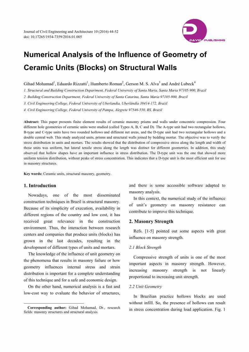
In Brazilian practice hollows blocks are used without infill. So, the presence of hollows can result in stress concentration during load application. Fig. 1
D DAVID PUBLISHING
Numerical Analysis of the Influence of Geometry of Ceramic Units (Blocks) on Structural Walls
45
shows the different geometries of blocks proposed in the Brazilian standard NBR 15270-2 [6].
Studies by Ganesan and Ramamurthy [7] evaluated the influence of different unit geometries and mortar properties over concrete masonry using the finite elements method. Stack bond prisms with three units high were simulated using a heterogeneous elastic-linear model.
Three different unit geometries were tested: (1) units with three hollows; (2) units with two hollows and standard dimensions; (3) units with two hollows and a double center. Different mortar properties were simulated using four different elasticity modulus ratios (Eb/Em): 1.0, 1.5, 2.0 and 2.8, with a constant Eb. The elasticity modulus ratio is important to analyze the influence of mortar on the failure mode and strength of masonry. The ratio
between net and gross areas was kept constant. Even being constant, the relation between net and
gross area were higher in units with three hollows. When compared to units with two hollows, the ones with a simple central web showed higher stress levels than the ones with double central web units. Therefore, unit’s geometry influences the level and distribution of stress in masonry and masonry efficiency varies by changing geometry and type of layer.
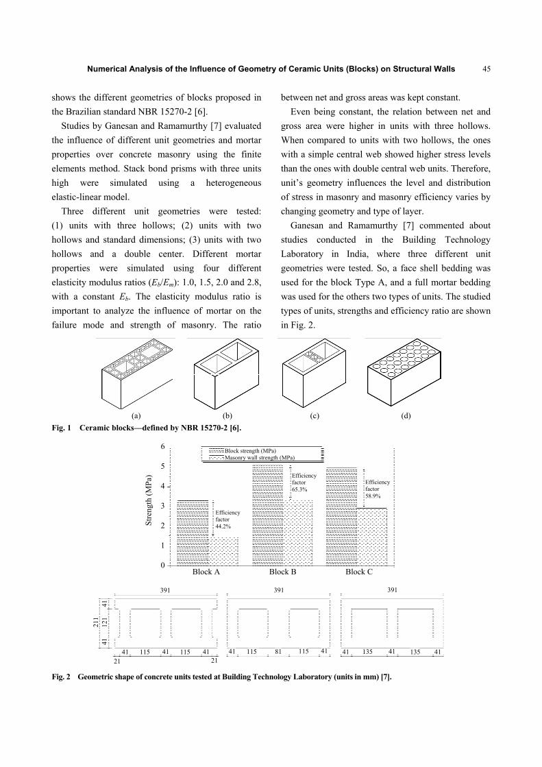
Ganesan and Ramamurthy [7] commented about studies conducted in the Building Technology Laboratory in India, where three different unit geometries were tested. So, a face shell bedding was used for the block Type A, and a full mortar bedding was used for the others two types of units. The studied types of units, strengths and efficiency ratio are shown in Fig. 2.
(a) (b) (c) (d)
Fig. 1 Ceramic blocks—defined by NBR 15270-2 [6].
Fig. 2 Geometric shape of concrete units tested at Building Technology Laboratory (units in mm) [7].
Block strength (MPa) Masonry wall strength (MPa)
Efficiency factor 44.2%
Efficiency factor 65.3%
Efficiency factor 58.9%
Stre
ngth
(MPa
)
6
5
4
3
2
1
0Block A Block B Block C
21 41 115 41 115 41
21 41 115 81 115 41 41 135 41 135 41
391 391 391
41
41
121
211
Numerical Analysis of the Influence of Geometry of Ceramic Units (Blocks) on Structural Walls
46
The researchers also pointed out the relevance of studying unit geometry to achieve a high efficiency of structural walls.
3. Materials and Components of Masonry
The main component used when manufacturing ceramic units is red clay. It contains silica, aluminum silicate and ferrous oxides. These components with an average grain size of 0.005 mm result in a plastic material when moist, although it becomes stiff when dry. Another important feature of moist clay is cohesion, to keep the mold’s shape before and during the drying process.
During the manufacturing process, clay is dosed (formulated) to correct any faults or to amplify a specific feature, such as unit’s compressive strength or fire resistance. In Brazil, the compressive strength of the available units varies from 3 MPa (low strength) to 100 MPa (high strength).
Brazilian standards [6, 8, 9] require control of the physical properties of units used in structural masonry. The NBR 15270-2 [6] limits the acceptance of units to the control of dimensions, square, flatness and water absorption. The limits for these properties are shown
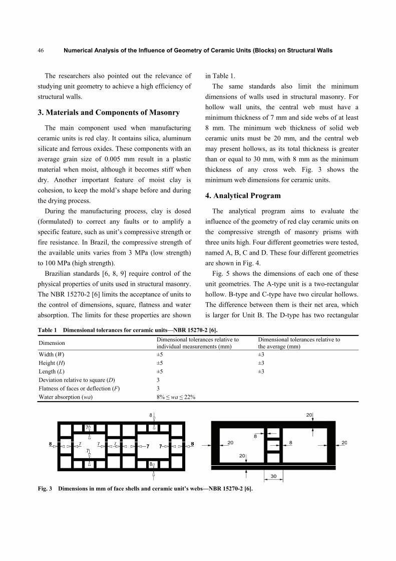
in Table 1. The same standards also limit the minimum
dimensions of walls used in structural masonry. For hollow wall units, the central web must have a minimum thickness of 7 mm and side webs of at least 8 mm. The minimum web thickness of solid web ceramic units must be 20 mm, and the central web may present hollows, as its total thickness is greater than or equal to 30 mm, with 8 mm as the minimum thickness of any cross web. Fig. 3 shows the minimum web dimensions for ceramic units.
4. Analytical Program
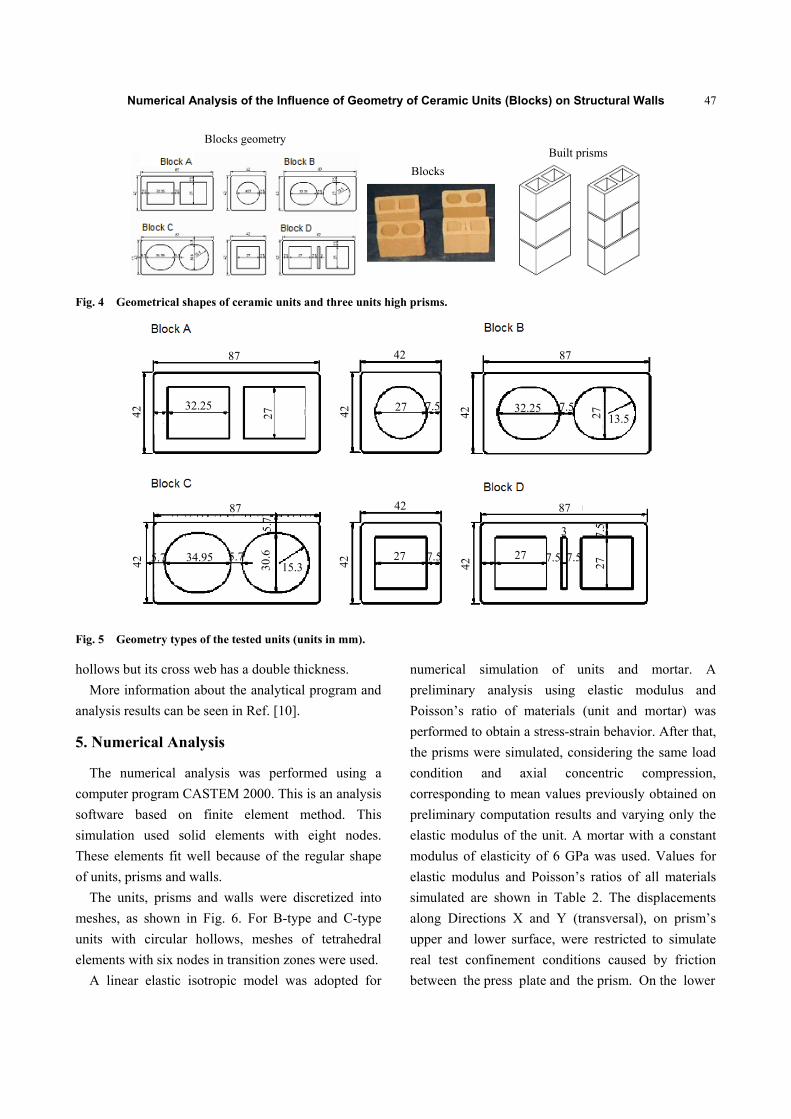
The analytical program aims to evaluate the influence of the geometry of red clay ceramic units on the compressive strength of masonry prisms with three units high. Four different geometries were tested, named A, B, C and D. These four different geometries are shown in Fig. 4.
Fig. 5 shows the dimensions of each one of these unit geometries. The A-type unit is a two-rectangular hollow. B-type and C-type have two circular hollows. The difference between them is their net area, which is larger for Unit B. The D-type has two rectangular
Table 1 Dimensional tolerances for ceramic units—NBR 15270-2 [6].
Dimension Dimensional tolerances relative to individual measurements (mm)
Dimensional tolerances relative to the average (mm)
Width (W) ±5 ±3 Height (H) ±5 ±3 Length (L) ±5 ±3 Deviation relative to square (D) 3 Flatness of faces or deflection (F) 3 Water absorption (wa) 8% ≤ wa ≤ 22%
Fig. 3 Dimensions in mm of face shells and ceramic unit’s webs—NBR 15270-2 [6].
Numerical Analysis of the Influence of Geometry of Ceramic Units (Blocks) on Structural Walls
47
Fig. 4 Geometrical shapes of ceramic units and three units high prisms.
Fig. 5 Geometry types of the tested units (units in mm).
hollows but its cross web has a double thickness. More information about the analytical program and
analysis results can be seen in Ref. [10].
5. Numerical Analysis
The numerical analysis was performed using a computer program CASTEM 2000. This is an analysis software based on finite element method. This simulation used solid elements with eight nodes. These elements fit well because of the regular shape of units, prisms and walls.
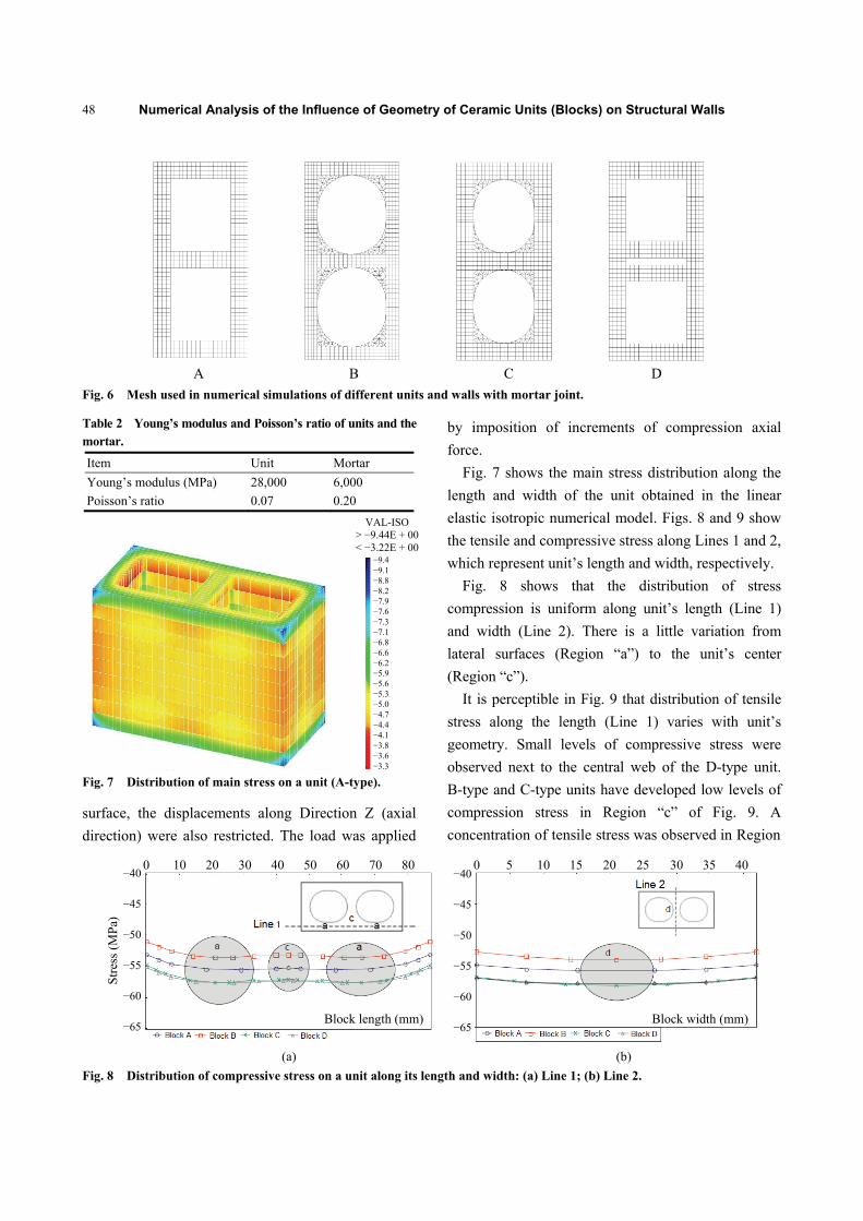
The units, prisms and walls were discretized into meshes, as shown in Fig. 6. For B-type and C-type units with circular hollows, meshes of tetrahedral elements with six nodes in transition zones were used.
A linear elastic isotropic model was adopted for
numerical simulation of units and mortar. A preliminary analysis using elastic modulus and Poisson’s ratio of materials (unit and mortar) was performed to obtain a stress-strain behavior. After that, the prisms were simulated, considering the same load condition and axial concentric compression, corresponding to mean values previously obtained on preliminary computation results and varying only the elastic modulus of the unit. A mortar with a constant modulus of elasticity of 6 GPa was used. Values for elastic modulus and Poisson’s ratios of all materials simulated are shown in Table 2. The displacements along Directions X and Y (transversal), on prism’s upper and lower surface, were restricted to simulate real test confinement conditions caused by friction between the press plate and the prism. On the lower
Blocks geometry
Blocks Built prisms
87
32.25
27
42
42
42
27 7.5 7.5
87
42 32.25 27
13.5
87
42 5.7 34.95 5.7
5.7
30.6
15.3 42
42
27 7.5
42
87
27
3
7.5 7.5
27
7.5
Numerical Analysis of the Influence of Geometry of Ceramic Units (Blocks) on Structural Walls
48
Fig. 6 Mesh used in numerical simulations of different units and walls with mortar joint.
Table 2 Young’s modulus and Poisson’s ratio of units and the mortar.
Item Unit Mortar Young’s modulus (MPa) 28,000 6,000 Poisson’s ratio 0.07 0.20
Fig. 7 Distribution of main stress on a unit (A-type).
surface, the displacements along Direction Z (axial direction) were also restricted. The load was applied
by imposition of increments of compression axial force.
Fig. 7 shows the main stress distribution along the length and width of the unit obtained in the linear elastic isotropic numerical model. Figs. 8 and 9 show the tensile and compressive stress along Lines 1 and 2, which represent unit’s length and width, respectively.
Fig. 8 shows that the distribution of stress compression is uniform along unit’s length (Line 1) and width (Line 2). There is a little variation from lateral surfaces (Region “a”) to the unit’s center (Region “c”).
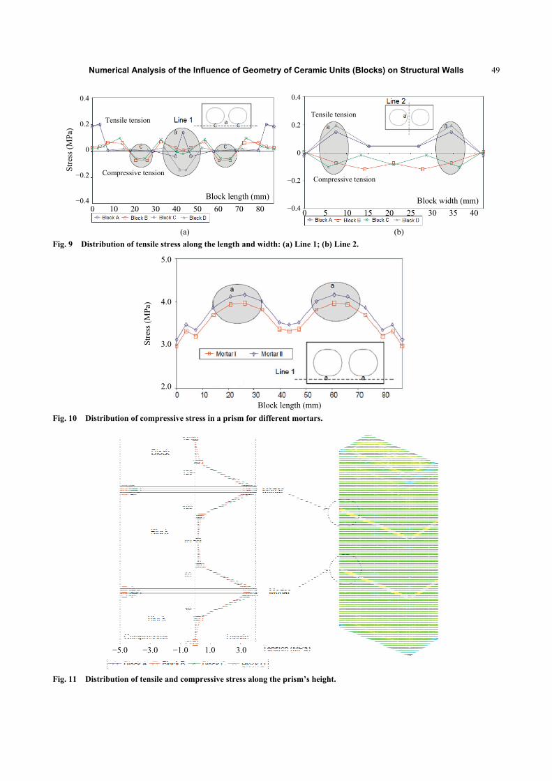
It is perceptible in Fig. 9 that distribution of tensile stress along the length (Line 1) varies with unit’s geometry. Small levels of compressive stress were observed next to the central web of the D-type unit. B-type and C-type units have developed low levels of compression stress in Region “c” of Fig. 9. A concentration of tensile stress was observed in Region
(a) (b)
Fig. 8 Distribution of compressive stress on a unit along its length and width: (a) Line 1; (b) Line 2.
A B C D
VAL-ISO > −9.44E + 00 < −3.22E + 00
−9.4 −9.1 −8.8 −8.2 −7.9 −7.6 −7.3 −7.1 −6.8 −6.6 −6.2 −5.9 −5.6 −5.3 −5.0 −4.7 −4.4 −4.1 −3.8 −3.6 −3.3
Block length (mm) Block width (mm)
Stre
ss (M
Pa)
−40
−45
−50
−55
−60
−65
−40
−45
−50
−55
−60
−65
0 10 20 30 40 50 60 70 80 0 5 10 15 20 25 30 35 40
Numerical Analysis of the Influence of Geometry of Ceramic Units (Blocks) on Structural Walls
49
(a) (b)
Fig. 9 Distribution of tensile stress along the length and width: (a) Line 1; (b) Line 2.
Fig. 10 Distribution of compressive stress in a prism for different mortars.
Fig. 11 Distribution of tensile and compressive stress along the prism’s height.
Block length (mm) Block width (mm)
Stre
ss (M
Pa)
0.4
0.2
0
−0.2
−0.40 10 20 30 40 50 60 70 80 0 5 10 15 20 25 30 35 40
0.4
0.2
0
−0.2
−0.4
Compressive tension
Tensile tension Tensile tension
Compressive tension
5.0
4.0
3.0
2.0
Stre
ss (M
Pa)
Block length (mm)
−5.0 −3.0 −1.0 1.0 3.0
Numerical Analysis of the Influence of Geometry of Ceramic Units (Blocks) on Structural Walls
50
“a” of A-type units. When stress distribution is analyzed along Line 2 (width), geometry Types B and C had a different behavior from Types A and D, as shown in Region “a” of Fig. 9. For Types B and C, the stress in Region “a” was compression, and it was tension for Types A and D. The distribution of tensile stress in Region “a” along Line 2 of A-type and D-type units was uniform.
To evaluate the influence of mortar’s elastic modulus over the level of main stress compression developed at prism’s mortar joints, a simulation changing the values of mortar’s elastic modulus was conducted. Two values of mortar’s elastic modulus were tested, 4.5 GPa and 6 GPa. A small variation of stress distribution was observed between these two values of elastic modulus. The highest value was in the middle of the core’s face shell, highlighted in
Region “a” of Fig. 10. By comparing stress distribution in the unit and in
the mortar, compressive stress was induced to the mortar and tensile stress to the unit. Fig. 11 presents the maximum main stress in prisms along a vertical line beginning at the center of the lower unit and ending at the center of the upper unit. These numerical results showed that lateral confinement stress level in the mortar was approximately 4.5 MPa. This indicates that mortar works under tri-axial compression and unit works under biaxial tension-compression, as shown in Fig. 11.
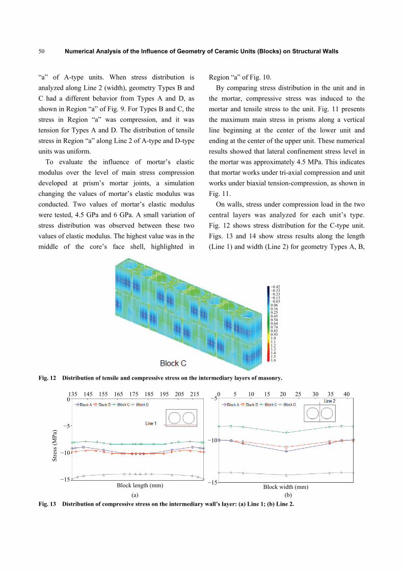
On walls, stress under compression load in the two central layers was analyzed for each unit’s type. Fig. 12 shows stress distribution for the C-type unit. Figs. 13 and 14 show stress results along the length (Line 1) and width (Line 2) for geometry Types A, B,
Fig. 12 Distribution of tensile and compressive stress on the intermediary layers of masonry.
(a) (b)
Fig. 13 Distribution of compressive stress on the intermediary wall’s layer: (a) Line 1; (b) Line 2.
Stre
ss (M
Pa)
−0.42−0.33 −0.23 −0.13 −0.03 0.06 0.16 0.25 0.45 0.54 0.64 0.74 0.83 0.93 1.0 1.1 1.2 1.3 1.4 1.5 1.6
0
−5
−10
−15
135 145 155 165 175 185 195 205 215
Block length (mm)
−5
−10
−15Block width (mm)
0 5 10 15 20 25 30 35 40
Numerical Analysis of the Influence of Geometry of Ceramic Units (Blocks) on Structural Walls
51
(a) (b)
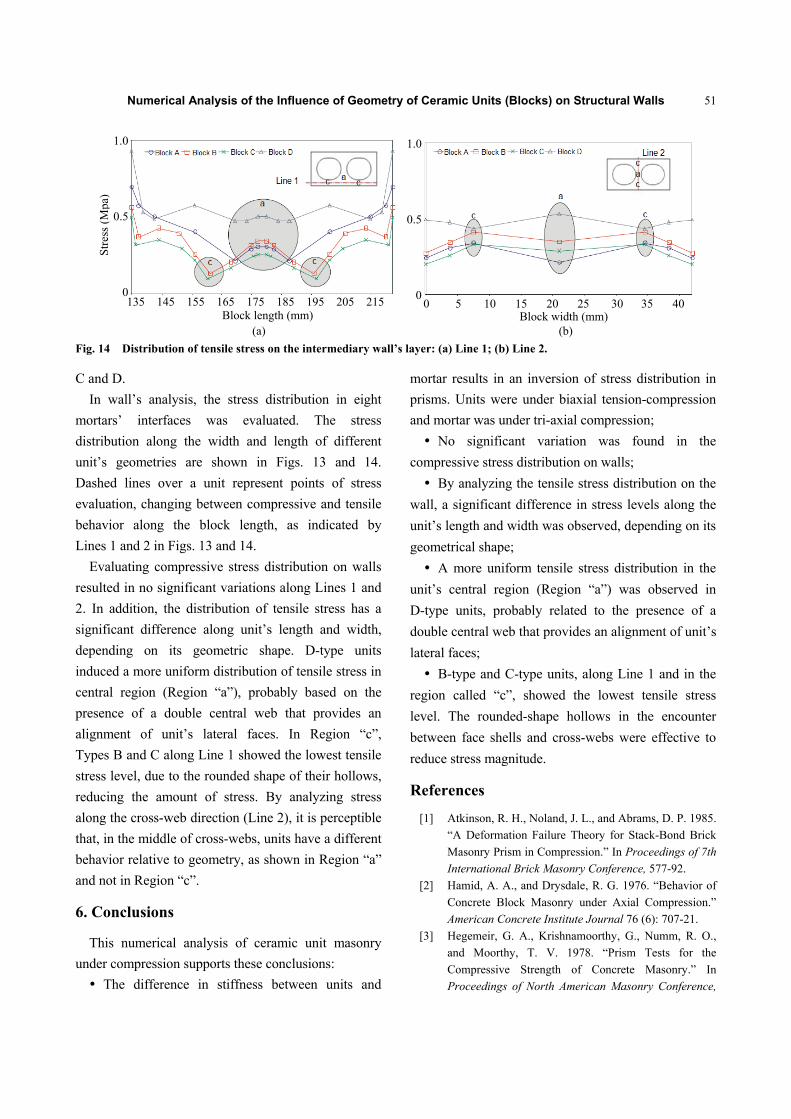
Fig. 14 Distribution of tensile stress on the intermediary wall’s layer: (a) Line 1; (b) Line 2.
C and D. In wall’s analysis, the stress distribution in eight
mortars’ interfaces was evaluated. The stress distribution along the width and length of different unit’s geometries are shown in Figs. 13 and 14. Dashed lines over a unit represent points of stress evaluation, changing between compressive and tensile behavior along the block length, as indicated by Lines 1 and 2 in Figs. 13 and 14.
Evaluating compressive stress distribution on walls resulted in no significant variations along Lines 1 and 2. In addition, the distribution of tensile stress has a significant difference along unit’s length and width, depending on its geometric shape. D-type units induced a more uniform distribution of tensile stress in central region (Region “a”), probably based on the presence of a double central web that provides an alignment of unit’s lateral faces. In Region “c”, Types B and C along Line 1 showed the lowest tensile stress level, due to the rounded shape of their hollows, reducing the amount of stress. By analyzing stress along the cross-web direction (Line 2), it is perceptible that, in the middle of cross-webs, units have a different behavior relative to geometry, as shown in Region “a” and not in Region “c”.
6. Conclusions
This numerical analysis of ceramic unit masonry under compression supports these conclusions: The difference in stiffness between units and
mortar results in an inversion of stress distribution in prisms. Units were under biaxial tension-compression and mortar was under tri-axial compression; No significant variation was found in the
compressive stress distribution on walls; By analyzing the tensile stress distribution on the
wall, a significant difference in stress levels along the unit’s length and width was observed, depending on its geometrical shape; A more uniform tensile stress distribution in the
unit’s central region (Region “a”) was observed in D-type units, probably related to the presence of a double central web that provides an alignment of unit’s lateral faces; B-type and C-type units, along Line 1 and in the
region called “c”, showed the lowest tensile stress level. The rounded-shape hollows in the encounter between face shells and cross-webs were effective to reduce stress magnitude.
References
[1] Atkinson, R. H., Noland, J. L., and Abrams, D. P. 1985. “A Deformation Failure Theory for Stack-Bond Brick Masonry Prism in Compression.” In Proceedings of 7th
International Brick Masonry Conference, 577-92. [2] Hamid, A. A., and Drysdale, R. G. 1976. “Behavior of
Concrete Block Masonry under Axial Compression.” American Concrete Institute Journal 76 (6): 707-21.
[3] Hegemeir, G. A., Krishnamoorthy, G., Numm, R. O., and Moorthy, T. V. 1978. “Prism Tests for the Compressive Strength of Concrete Masonry.” In Proceedings of North American Masonry Conference,
Stre
ss (M
pa)
Block length (mm) Block width (mm)
1.0
0.5
00 5 10 15 20 25 30 35 40135 145 155 165 175 185 195 205 215
1.0
0.5
0

Numerical Analysis of the Influence of Geometry of Ceramic Units (Blocks) on Structural Walls
52
181-7. [4] Hilsdorf, H. K. 1969. Investigation into the Failure
Mechanism of Brick Masonry Loaded in Axial Compression. Houston: Gulf Publishing Company.
[5] Khoo, C. L. 1972. “A Failure Criterion for Brickwork in Axial Compression.” Ph.D. thesis, University of Edinburgh, Scotland.
[6] Brazilian Standard. 2005. Blockwork Clay Masonry Blocks. NBR 15270-2. Rio de Janeiro: Brazilian Standard.
[7] Ganesan, T. P., and Ramamurthy, K. 1992. “Behavior of Concrete Hollow-Block Masonry Prisms under Axial
Compression.” Journal of Structural Engineering 118: 1751-69.
[8] Brazilian Standard. 1985. Masonry Structures—Method of Test. NBR 8949. Rio de Janeiro: Brazilian Standard.
[9] Brazilian Standard. 1995. Mortar—Compressive Strength. NBR 13279. Rio de Janeiro: Brazilian Standard.
[10] Rizzatti, E. 2003. “Block Geometry Influence on the Mechanical Strength on Masonry Structures.” Ph.D. thesis, UFSC (Federal University of Santa Catarina), Florianópolis. (in Portuguese)