Embed Size (px)
Citation preview

11th International Workshop on Ship and Marine Hydrodynamics
Hamburg, Germany, September 22-25, 2019
Numerical Analysis of Vortex-Induced Yaw Motion of a Paired-Column Semi-
Submersible in Currents
Weiwen Zhao, Decheng Wan*
State Key Laboratory of Ocean Engineering, School of Naval Architecture, Ocean and Civil
Engineering Shanghai Jiao Tong University, Collaborative Innovation Center for Advanced Ship
and Deep-Sea Exploration, Shanghai, China
*Corresponding author: [email protected]
ABSTRACT
Vortex-induced motions (VIM) is a severe engineering problem for floating structures with slender
columns. Moreover, recent studies on VIM of multi-column floating platforms showed that VIM also
involves prominent yaw motions. In this paper, numerical simulations of VIM for a paired-column semi-
submersible with transverse, inline and yaw degree-of-freedom are performed by our in-house CFD solver
naoe-FOAM-SJTU. To avoid mesh distortion induced by yaw motion, a multi-block overset mesh is applied
for the fluid domain. In order to accurately predict the flow separation and wake flow, the SST-DDES
turbulence model is utilized. Vortex-induced yaw (VIY) is observed during VIM simulations. For high
current velocity cases, multi-frequency component for yaw is discovered. The variation of yaw frequencies
at different reduced velocities and current headings are discussed. Drag and lift, as well as rotational moment
on each column member are analyzed.
1 INTRODUCTION
During last decades, researchers and engineers were devoted to the study of vortex-induced motions of
floating offshore structures. As is known to all, the vortex shedding around bluff body will cause alternative
pressure changes on both sides as well as back of the body. For floating offshore platforms with vertical
column structures, the periodic pressure change is main cause of formation of the vortex-induced motions, or
VIM. Previous studies of VIM of Spars[1] and mono-column[2] showed that for single-column floating
structures, VIM is dominated by transverse (sway) and inline (surge) motions. However, for semi-
submersible platforms with multiple columns, the vortex shedding behaviours and frequencies on each
column can be different due to the interference between columns under varies current headings. That will
consequently results in different oscillating drag and lift forces on each column in terms of frequency,
amplitude and phase. This is commonly known as the main reason of yaw motions in VIM for multi-column
semi-submersible platforms.
There has been extensive works on the VIM study of semi-submersible platforms both experimentally
and numerically. In the very beginning of VIM study of semi-submersible, however, researchers were
concentrating on the transverse and inline motion responses of the platform. Yaw motion due to VIM hasn’t
been discussed too much, see for example, Rijken and Leverette[3], Hong et al. [4]. It was Waals et al. [5] who
first reported significant yaw motion in their VIM model test of semi-submersible in towing tank. According
to their study, the yaw amplitude was up to 6.79 degree for some specific towing direction and pontoon
configuration. They conjecture that yaw motion of multi-column floaters induced by current could be due to
the galloping phenomenon as the yaw amplitude is not self-limiting but rather increases monotonically with
tow speed. In the subsequent experimental studies by Magee et al. [6], Gonçalves et al. [7,8], Liu et al. [9], they
also confirmed the yaw motions in VIM for multi-column semi-submersible platforms. As the computational
power increases, numerical simulations based on computational fluid dynamics (CFD) method have also

2
been carried out to the VIM study of semi-submersible platforms. Tan et al. [10] simulated the VIM of a
multi-column floating platform with commercial CFD software Star-CCM+ and good agreement between
model test and CFD simulations were obtained. They found that the yaw motion is sensitive to current
headings. The 0 degree current heading gives the largest yaw response. Lee et al. [11] performed full-scale and
model-scale CFD simulations of VIM response of a deep draft semi-submersible. Transverse, inline and yaw
motions are considered in the simulations. Their results showed that the yaw response is also self-limited as
transverse motion. The lock-in for yaw however is more complicated than that of transverse motion.
Due to the wake interference contributed by columns and pontoons, VIM characteristics especially the
yaw motion for semi-submersible platform is very complicated. Amongst the VIM studies of semi-
submersibles which discussed yaw motion characteristics, Liu et al. [12] performed both experimental and
three-dimensional numerical simulations on the VIM of semi-submersibles. In their study, the yaw motion
responses between 0 and 45 degree current headings was distinctly different. The yaw amplitude reached
peak value of about 4.5 to 5 degree at 0 degree current heading in the range of non-dimensional reduced
velocity from 5 to 8, and decreased sharply. However, the 45 degree current heading case showed the yaw
amplitude increase until reduced velocity becomes larger than 8 and then remained at a stable level as
reduced velocity continues increasing. To better understanding the yaw characteristics in semi-submersible
VIM, the current study performs CFD simulations of a paired-column semi-submersible (PC Semi) platforms
with eight columns. Detailed flow field information including three-dimensional vortex structures, as well as
force analysis on each individual column will be discussed to reveal the mechanism of yaw motion for multi-
column semi-submersibles.
2 MODEL AND DEFINITIONS
The semi-submersible model used in present CFD study is a deep-draft semi-submersible with eight
columns. Related model tests have been carried out by Zou et al. [13,14] at towing tank in UC Berkley and
MARIN with different scale ratio, respectively. The larger model with scale ration 1:54 is adopted in the
present study. The model consists of four outer columns and four inner columns with different column sizes.
The three-dimensional model of the PC Semi is depicted in Figure 1. Detailed geometric size of the PC Semi
can be referred to Zhao et al. [15] and will not described here.
Figure 1: Three-dimensional model of the PC Semi.
The non-dimensioned parameter reduced velocity, rU , is usually presented in the VIM study to
represent the current velocity or towing velocity, which is defined as
nr
UTU
D (1)
where U is the current velocity or towing velocity, nT is the natural transverse period of the platform under
mooring configuration in still water, D is the characteristic diameter of columns. For conventional semi-

3
submersible with cylinder or square columns, D is the projection diameter perpendicular to current direction.
As for PC Semi, D is the diagonal length of the outer column cross section.
For yaw motion analysis, another reduced velocity based on the natural yaw period is usually
presented, which is defined as
,
,
n yaw
r yaw
UTU
D (2)
in which, ,n yawT is the natural yaw period.
When performing analysis on the force and motion characteristics, the lift and drag coefficients, as
well as the nominal motion response are introduced. The lift and drag coefficients represent the
nondimensional lift forces and drag forces in transverse and inline direction, respectively. They can be
expressed as
2
( )( )
0.5
y
L
F tC t
U A (3)
2
( )( )
0.5
xD
F tC t
U A (4)
where is the fluid density, U is the flow velocity, yF and
xF are hydrodynamic forces act on the
platform in the transverse and inline directions, respectively. A is the projected area perpendicular to flow
direction.
In addition, the yaw moment coefficient is defined as
2
( )( )
0.5
zM
M tC t
U AB (5)
where B is the overall width of the semi-submersible platform.
The motion characteristics of VIM response is defined by the standard deviation of motion amplitude.
The nominal transverse and yaw response are defined as:
2 ( ( ))
( / )y
y std
A tA D
D
(6)
( ) 2 ( ( ))stdYaw yaw t (7)
where, represents the standard deviation of the transverse or yaw motion time series.
3 NUMERICAL APPROACHES
3.1 CFD solver
The CFD solver naoe-FOAM-SJTU [15–17] is used for all the simulations throughout this paper. This
solver is developed on top of the OpenFOAM framework. It solves the single-phase incompressible flow on
a finite volume collocated grid. The coupled pressure and velocity are solved by the segregated PIMPLE
method (merged PISO and SIMPLE), in which the standard PISO loop is wrapped by an outer iteration loop
with possible under-relaxation of field variables. Differs from the standard PIMPLE family solvers with
dynamic motion capabilities in OpenFOAM, naoe-FOAM-SJTU utilizes Euler angle rather than quaternion
to describe the motion state and rewrites the six-degree-of-freedom rigid body motion solver combined with
the dynamic overset grid capability. The dynamic overset grid is realized by running OpenFOAM flow

4
solver and overset grid assembler Suggar++[18] in different processors. For details about the governing
equations and solving procedures of the solver, one can refer to Shen et al. [16] and Zhao et al. [15].
For turbulence modelling, RANS and DES are available in the current CFD solver. Previous studies [19,20] compared standard k SST with DDES model and showed that VIM response obtained by DDES
were closer to experimental results. The transverse VIM response of k SST is slightly larger than DDES.
This is due to the excessive eddy viscosity produced by RANS for high Reynolds number flow with strong
unsteady separation. For VIM simulations, DES is preferred for turbulence modelling. In this paper, the SST-
DDES model is employed for turbulence modelling. SST-DDES [21] is a “delayed” version of DES, which
addresses the “grey area” problems of the original DES model. It can avoids modelled-stress depletion (MSD)
which is caused by improper wall-parallel grid spacing in boundary layer. The consequence of MSD, called
grid-induced separation (GIS), can also be eliminated.
To deal with large amplitude rigid body motions, the solver applies a six-degrees-of-freedom rigid
body motion equation together with the dynamic overset grid. For semi-submersible VIM, the dominant
motions are transverse, inline and yaw motions. Therefore in the present VIM study, motions of the semi-
submersible platform is obtained by solving the motion equation and is constrained in the horizontal plane.
In other words, only transverse, inline and yaw motions are allowed. As for the dynamic grid handling, the
overset grid technique can avoid grid distortion and preserve grid quality by moving individual composite
grid components freely without mesh deforming.
3.2 Case setup
The computational domain extends to 7 4 3.5B B T (length × width × height), in which B is the
overall width and T is the draft of the hull, as shown in Figure 2. According to previous studies [11,22], this
domain size is large enough to eliminate the effect of two lateral sides, downstream and bottom.
Figure 3 illustrates the overset grid system used in the present numerical simulations. The unstructured
polyhedral overset grid consists of two overlapping mesh blocks: the background mesh in red and the hull
mesh in blue. The background mesh is hexahedral with a uniform grid spacing bS and is generated with the
blockMesh utility which is a hexahedral mesh generator. The hull mesh is generated by the snappyHexMesh
utility which is a polyhedral mesh generator based on Cartesian cut-cell approach. The initial base grid size
of hull mesh is same as background grid spacing. This ensures all fringe cells could find its corresponding
donor cells and avoid orphan cells during overset DCI calculation. Cells in critical region around the hull
have been refined up to 4 refinement levels. Ten prism cell layers with expansion ratio of 1.45 are applied to
the hull boundary in order to capture boundary layer development. The y+ for the first layer satisfies y+<1 to
make sure that the first layer cells are in the viscous sublayer. The final cell numbers in total is 2.43 million.
Figure 2: Computational domain.

5
Figure 3: Overset grid system and mesh refinement.
4 RESULTS AND DISCUSSIONS
4.1 Motion responses
Figure 4 presents the results of nominal transverse response at 0 and 45 degree current headings. The
hollow markers represent the experimental data from MARIN which is taken from Zou et al.[14]. The 0
degree cases has more pronounced transverse motion than 45 degree cases. This contradicts with the results
of conventional semi-submersible. The reason is the difference of current heading definition between PC
Semi and conventional four-column semi-submersible. The current heading definition of conventional semi-
submersible is consistent with column flow incident angle. However, for PC Semi the current heading
definition is different. E.g., at 0 degree current heading, the column flow incident angle is 45 degree and at
45 degree current heading, columns are parallel with flow direction. It implies that for multi-column floaters
with square and rectangular columns, the 45 degree flow incident angle for columns gives the larger
transverse VIM response than 0 degree incident angle.
Figure 4: Nominal transverse motion response. Source: Zhao et al. [23]
Figure 5 shows the spectral analysis of motion response in the transverse direction at different current
headings. The 0 degree case gives the strongest transverse motion amplitudes compared with other current
headings. Transverse motion frequencies of 0-degree and 22.5-degree current heading at Ur=5 is close to the
natural transverse frequency nf , which indicates a resonant behavior on this degree-of-freedom. However,
even if the transverse motion frequency is close to the nf , the transverse motion amplitude is still small for
45-degree heading. It can be attributed to the weak vortex shedding around columns when the column is
aligned to incoming flow direction.
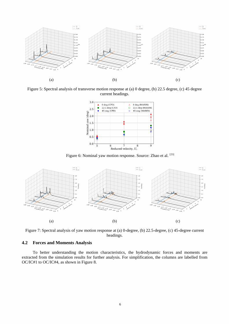
The nominal yaw motions, as shown in Figure 6, is different from transverse motions. The 0 degree
current heading at Ur=9 gives highest yaw response among all cases. Spectral analysis are also performed for
yaw motion and the results are given in Figure 7. From the perspective of frequency domain analysis, the
yaw motion is more complicated than transverse motion. For high reduced velocities, there are always
multiple frequency components excitations that drives the platform rotating at different frequencies. At 0
degree headings, the yaw are dominated by two peak frequencies. For 22.5-degree and 45-degree cases, the
dominant yaw frequencies are weaker and the frequency bands are wider.
6
(a) (b) (c)
Figure 5: Spectral analysis of transverse motion response at (a) 0 degree, (b) 22.5 degree, (c) 45 degree
current headings.
Figure 6: Nominal yaw motion response. Source: Zhao et al. [23]
(a) (b) (c)
Figure 7: Spectral analysis of yaw motion response at (a) 0-degree, (b) 22.5-degree, (c) 45-degree current
headings.
4.2 Forces and Moments Analysis
To better understanding the motion characteristics, the hydrodynamic forces and moments are
extracted from the simulation results for further analysis. For simplification, the columns are labelled from
OC/IC#1 to OC/IC#4, as shown in Figure 8.

7
Figure 8: The mooring system and labelling of outer and inner columns for PC Semi.
Figure 9 gives the lift forces on the upstream columns of the PC Semi for 0-degree heading. It can be
seen clearly the frequencies and phases for lift forces are highly coincident amongst the four upstream outer
and inner columns, OC#1/#2 and IC#1/#2, which indicating a strong synchronization amongst the vortex
shedding of upstream columns. When the current heading changes to 22.5 and 45 degrees, the lift forces
amplitude decreases compared to 0-degree heading. It’s interesting to know that lift force frequencies for
upstream columns are all increasing. More importantly, phase shift of lift force exists between any of two
columns. The frequency and phase diversity scatter the component of each columns in total lift forces and
result in smaller transverse motion responses.
(a) (b) (c)
Figure 9: Hydrodynamic lift forces of each upstream columns for 0-degree heading at reduced velocity of (a)
Ur=5, (b) Ur=7, (c) Ur=9.
(a) (b) (c)
Figure 10: Hydrodynamic yaw moments of each upstream columns for 0-degree heading at reduced velocity
of (a) Ur=5, (b) Ur=7, (c) Ur=9.
Figure 10 shows the yaw moment of upstream columns for 0-degree heading at different reduced
velocities. A first sight, frequency and phase of yaw moments for upstream columns are similar to lift forces.
Phase synchronization exists between upstream columns at reduced velocity Ur=5. As reduced velocity

8
increases to 7 and 9, frequency increases and phase shift occurs. It seems the phase synchronization of
moment should amplify the yaw motion response. It is however vice versa, Ur=5 gives the smallest yaw
response, see Figure 6.
To explain this contradiction, moments on four outer columns are further analysed and presented in
Figure 11. The yaw moments on inner columns are omitted due to small contribution to yaw motion.
Surprisingly, at Ur=5, the phase angle offset between upstream and downstream outer columns is always 180
degree. As a consequence, the total yaw moment is cancelling out and keeps at a small value, which is
responsible for the small yaw motion amplitude. For Ur=7 and 9 cases, although the time histories of yaw
moment are modulated and not as regular as Ur=5, there are phase synchronizations between upstream and
downstream columns, which contributes to the amplification of yaw motion response.
Figure 11 gives another example of yaw moments for 22.5-degree current heading. The phase shift of
yaw moment is also observed at Ur=5 in this conditions, but not for high reduced velocities Ur=7 and 9. The
45-degree current heading cases show similar phenomenon and will not be presented here.
(a) (b) (c)
Figure 11: Hydrodynamic yaw moments of each outer columns for 0-degree heading at reduced velocity of
(a) Ur=5, (b) Ur=7, (c) Ur=9.
(a) (b)
Figure 12: Non-dimensional vorticity contour on the half-draft plane for 0 degree heading at Ur=5, coloured
by (b) spanwise vorticity, (b) vorticity magnitude.
Figure 12 depicts the vorticity contour on the half-draft plane for 0 degree. The contour are coloured
by the non-dimensional spanwise vorticity and vorticity magnitude. The expected synchronization of vortex
shedding around the upstream outer and inner columns are observed. In Figure 12(b), some small size eddies
occur between upstream and downstream columns, which confirms the three-dimensional effect of vortex
shedding from upstream columns. These eddies make the VIM especially yaw motion response more
complicated and need to be further studied in the future.
5 CONCLUSION
In this paper, the VIM including transverse, inline and yaw motions of a paired-column semi-
submersible are numerically simulated using the naoe-FOAM-SJTU CFD solver. Based on the comparison
between CFD and model test results, it is concluded that the present CFD results suit well with experimental

9
data in terms of statistic values for transverse and yaw motion response. In addition, the following
conclusions are drawn:
1. Under 0-degree current heading (45 flow incident angle with respect to column), the PC Semi gives
the largest transverse motion amplitude.
2. For 0-degree current heading, transverse force synchronization exists amongst four upstream outer
and inner columns.
3. For low reduced velocity Ur=5, yaw moment between upstream and downstream columns has a
phase angle of 180 degrees.
4. For high reduced velocity Ur=7, yaw moment synchronization is observed amongst four outer
columns.
ACKNOWLEDGEMENTS
This work is supported by the National Natural Science Foundation of China (51879159, 51490675,
11432009, 51579145), Chang Jiang Scholars Program (T2014099), Shanghai Excellent Academic Leaders
Program (17XD1402300), Program for Professor of Special Appointment (Eastern Scholar) at Shanghai
Institutions of Higher Learning (2013022), Innovative Special Project of Numerical Tank of Ministry of
Industry and Information Technology of China (2016-23/09) and Lloyd’s Register Foundation for doctoral
student, to which the authors are most grateful.
REFERENCES
[1] Finnigan, T., Roddier, D. Spar VIM model tests at supercritical reynolds numbers[C]. In Proceedings of the 26th
International Conference on Offshore Mechanics and Arctic Engineering. San Diego, California, USA, 2007, 3:
731–740.
[2] Gonçalves, R.T., Fujarra, A.L.C., Rosetti, G.F., et al. Mitigation of vortex-induced motion (VIM) on a
monocolumn platform: forces and movements[J]. Journal of Offshore Mechanics and Arctic Engineering. 2010,
132(4): 041102.
[3] Rijken, O., Leverette, S. Experimental study into vortex induced motion response of semi submersibles with
square columns[C]. In Proceedings of the 27th International Conference on Offshore Mechanics and Arctic
Engineering. Estoril, Portugal, 2008, 1: 263–276.
[4] Hong, Y., Choi, Y., Lee, J., et al. Vortex-induced motion of a deep-draft semi-submersible in current and
waves[C]. In Proceedings of the 18th International Offshore and Polar Engineering Conference. Vancouver,
British Columbia, Canada, 2008, 3: 453–459.
[5] Waals, O.J., Phadke, A.C., Bultema, S. Flow induced motions of multi column floaters[C]. In Proceedings of the
26th International Conference on Offshore Mechanics and Arctic Engineering. San Diego, California, USA, 2007,
1: 669–678.
[6] Magee, A., Sheikh, R., Guan, K.Y.H., et al. Model tests for VIM of multi-column floating platforms[C]. In
Proceedings of the ASME 30th International Conference on Ocean, Offshore and Arctic Engineering. Rotterdam,
The Netherlands, 2011, 7: 127–136.
[7] Gonçalves, R.T., Nishimoto, K., Rosetti, G.F., et al. Experimental study on vortex-induced motions (VIM) of a
large-volume semi-submersible platform[C]. In Proceedings of the 30th International Conference on Ocean,
Offshore and Arctic Engineering. Rotterdam, The Netherlands, 2011, 7: 1–9.
[8] Gonçalves, R.T., Rosetti, G.F., Fujarra, C., et al. Vortex-induced yaw motion (VIY) of a large-volume semi-
submersible platform[C]. In Proceedings of the 22nd International Offshore and Polar Engineering Conference.
Rhodes, Greece, 2012, 3: 572–578.
[9] Liu, M., Xiao, L., Lu, H., et al. Experimental study on vortex-induced motions of a semi-submersible with square
columns and pontoons at different draft conditions and current incidences[J]. International Journal of Naval
Architecture and Ocean Engineering. 2017, 9(3): 326–338.
[10] Tan, J.H.C., Magee, A., Kim, J.W., et al. CFD simulation for vortex induced motions of a multi-column floating
platform[C]. In Proceedings of the 32nd International Conference on Ocean, Offshore and Arctic Engineering.
Nantes, France, 2013, 7: V007T08A066.
[11] Lee, S.-K., Chien, H.-P., Gu, H. CFD study of deep draft semisubmersible VIM[C]. In Proceedings of the
Offshore Technology Conference-Asia. Kuala Lumpur, Malaysia, 2014.
[12] Liu, M., Xiao, L., Liang, Y., et al. Experimental and numerical studies of the pontoon effect on vortex-induced
motions of deep-draft semi-submersibles[J]. Journal of Fluids and Structures. 2017, 72: 59–79.

10
[13] Zou, J., Poll, P., Roddier, D., et al. VIM testing of a paired column semi submersible[C]. In Proceedings of the
ASME 32nd International Conference on Ocean, Offshore and Arctic Engineering. Nantes, France, 2013, 7:
V007T08A001.
[14] Zou, J., Poll, P., Antony, A., et al. VIM model testing and VIM induced mooring fatigue of a dry paired-column
semisubmersible platform[C]. In Proceedings of the Offshore Technology Conference. Houston, Texas, USA,
2014.
[15] Zhao, W., Zou, L., Wan, D.C., et al. Numerical investigation of vortex-induced motions of a paired-column semi-
submersible in currents[J]. Ocean Engineering. 2018, 164: 272–283.
[16] Shen, Z., Wan, D.C., Carrica, P.M. Dynamic overset grids in OpenFOAM with application to KCS self-
propulsion and maneuvering[J]. Ocean Engineering. 2015, 108: 287–306.
[17] Wang, J., Zou, L., Wan, D.C. CFD simulations of free running ship under course keeping control[J]. Ocean
Engineering. 2017, 141: 450–464.
[18] Noack, R.W., Boger, D.A., Kunz, R.F., et al. Suggar++: An improved general overset grid assembly
capability[C]. In 19th AIAA Computational Fluid Dynamics Conference. San Antonio, Texas, USA, 2009.
[19] Kim, S.J., Spernjak, D., Holmes, S., et al. Vortex-induced motion of floating structures: CFD sensitivity
considerations of turbulence model and mesh refinement[C]. In Proceedings of the 34th International Conference
on Ocean, Offshore and Arctic Engineering. St. John’s, Newfoundland, Canada, 2015, 2: V002T08A057.
[20] Vinayan, V., Antony, A., Halkyard, J., et al. Vortex-induced motion of deep-draft semisubmersibles: A CFD-
based parametric study[C]. In Proceedings of the 34th International Conference on Ocean, Offshore and Arctic
Engineering. St. John’s, Newfoundland, Canada, 2015, 2: V002T08A003.
[21] Gritskevich, M.S., Garbaruk, A.V., Schütze, J., et al. Development of DDES and IDDES formulations for the k-ω
shear stress transport model[J]. Flow, Turbulence and Combustion. 2011, 88(3): 431–449.
[22] Liang, Y., Tao, L. Interaction of vortex shedding processes on flow over a deep-draft semi-submersible[J]. Ocean
Engineering. 2017, 141: 427–449.
[23] Zhao, W., Wan, D.C., Chen, G. Vortex shedding and its impacts on the motions of a paired-column semi-
submersible[C]. In Proceedings of the 28th International Offshore and Polar Engineering Conference. Sapporo,
Japan, 2018, 3: 916–923.