Embed Size (px)
Citation preview

2014-03-18
1
Numerical Experiments of Fluid-Structure Interaction with CFX
Hongik Univercity, KoreaSeung Oh Lee
Contents
1. Introduction: Fluid-Structure Interaction2. Theory and Background3. Vibration of Structure induced by Gate Opening4. Floating Type Photovoltaic Composite Structure5. Conclusion

2014-03-18
2
Introduction
• Fluid-Structure Interaction(FSI)- One-way: Conventional method, Sequentially
- Two-way: Improved method, Simultaneously
TurbulentMixture
Radiationin Solid
Solid Dynamic Moving Mesh
Stress ThermalStress
Solid Dynamic
Force, Flux(Surface)
Temperature(Volume)
Fluid Structure
TurbulentMixture
Radiationin Solid
Solid Dynamic Moving Mesh
Stress ThermalStress
Solid Dynamic
Surface fluid force
Surfaceposition & velocity
Fluid Structure
By ANSYS
Introduction
• Comparison between One-way and Two-way· Displacement
· Frequency spectrum
Red: One-wayBlack: Two-way
(FK Benra et al., 2011)
Natural frequency: 0.78 Hz

2014-03-18
3
FSI Modeling Approaches
1-way(uncoupled)
2-way
ExplicitImplicitIterative
Fully Coupled
Wea
kSt
rong
Very
Stro
ng
Small deformations(excluding turbulence induced)
Blade deformations, Rigid bodies
Vortex induced vibrations
Biomedical,Membranes
Phys
ical
Cou
plin
g
Numerical Coupling
by ANSYS User Manual
Sequentially Simultaneously
FSI: Two-way
• FSI describes the couple dynamics of fluid and structure mechanics.
• Types of FSI- Aerodynamics
: Computational Fluid Dynamics(CFD)- Bio-engineering
: Understanding of the flow of blood in vessels or heart.- Civil-engineering
: Vibration of structure, Turbulent flow
Fluid Structure
External force(Pressure or Thermal loads)
Structural deformation/moveFluid flow change

2014-03-18
4
Governing Equations: Fluid
• Computational Fluid Dynamics(CFD) - Navier-Stokes equation + ∙ = − + ∙ + - Conservation of Mass∫ = −∮ ∙
: flow velocity: fluid density: pressure: component of total stress tensor: body forces on the fluid per unit volume
Rate of change of mass Net inflow of mass
Governing Equations: Fluid
- Conservation of Momentum = − ∙ − + 2 ∙ + - Conservation of Energy
∫ + = −∮ + ∙ +∫ ∙ + ∮ ∙ − ∮ ∙
Rate of change of momentum
Net inflow of momentum
Total pressure Total viscous force Total body force
Rate of change of kinetic+internal energy
Net inflow of kinetic+internal energy
Work done by body forces
Net work done by the stress tensor
Net heat flow

2014-03-18
5
Governing Equations: Structure
• Heat conduction equation = + + + • Equation of structural dynamics + + =
+ + =
: Density: Specific heat capacity: Thermal conductivity: Heat generation
: Mass: Damping coefficient: Stiffness: External force = ⁄ = ⁄
Governing Equations: Multiphysics
• The finite element formulation which treats a single phenomenon uses matrix algebra. = • Matrix Coupling = • Load Vector Coupling 00 =
: Coefficient matrix : Vector of nodal unknowns : The known load vectorSubscript 1 is fluid; Subscript 2 is solid
From FLUID side◦ Conservative Interpolation
- Nodal forces: Fx, Fy, Fz- Nodal heat rates: Q◦ Non-Conservative Interpolation
- Nodal force fluxes: Fx”, Fy”, Fz”- Nodal heat fluxes: Q”
From SOLID side- Nodal displacements: Ux, Uy, Uz- Nodal temperatures: TEMP- Nodal velocities: Vx, Vy, VzRed: Coupled effect coefficient
Blue: Iteration for convergence

2014-03-18
6
Numerical Tool
• ANSYS CFXCommercial Computational Fluid Dynamics(CFD) program, used to simulate fluid flow in a variety of applications.Multiphysics: The ability to combine the effects of two or more different unified simulation environment.
Numerical Tool
• Advantage- Advanced solver technology using coupled algebraic multigrid
to achieving reliable and accurate solutions.- Uses second order numerics to get the most accurate predictions
possible.- Analysis of the multyphase flow by coupled solver using a
matrix method
• Disadvantage- Coupled solver takes a long time of calculation for a given time
step because all the variables is solved at the same time.

2014-03-18
7
Vibration of Structures Induced by Gate Opening
Example of FSI
• Introduction & PurposeIt is intended to confirm of vibration of solid and the applicability of the FSI.
• Geometry & Mesh, Initial & Boundary conditions
Inlet Outlet Height of gate opening
Variable hi ho h
Value(m) 0.40 0.15 0.10
Opening
OutletFluid-SolidInterface
Inlet
Bottom
Gate Fluid
Mesh size 0.05 m 0.01 m
Total mesh 27703 ea 24000 ea

2014-03-18
8
Example of FSI
Radial Sluice Gate
• IntroductionSluice gate is commonly a sliding barrier and control water levels and flow rates in rivers. Vibration of sluice gate is generated by the fluid flow.
• PurposeComparison of results from experiment with them from numerical simulation to verify results of fluid-structure interaction.
※Report of hydraulic experiments and observation of wave in Saemankum, 1994.• Experiment conditions
- Straight open channel with width 1.2 m, length 30 m, height 0.5 m- Constant upstream height: 0.32 m- Constant downstream height: 0.11 m
2014-03-18
9
Geometry & Mesh
• Gate Gate and gate arm - AcrylLifting lug - Steel
0.5 m
1.2 m
Value
Mesh size 0.03 m
Total mesh 34259 ea
PrototypeModel
Requiredvalue
Applyvalue
Scale 1 1/25
Unit weight 7.85 7.85 Acryl: 1.20 Steel: 7.85
Mass 320 ton 20.48 kg 20.90 kg
Elasticmodulus 2.01x10⁹ 8.04x10⁷ Acryl: 2.80x10⁷
Steel: 2.01x10⁹
Geometry & Mesh
• Fluid
1.2 m
0.8 m
3.5 m
Value
Mesh size 0.03 m
Total mesh 1699860 ea
2014-03-18
10
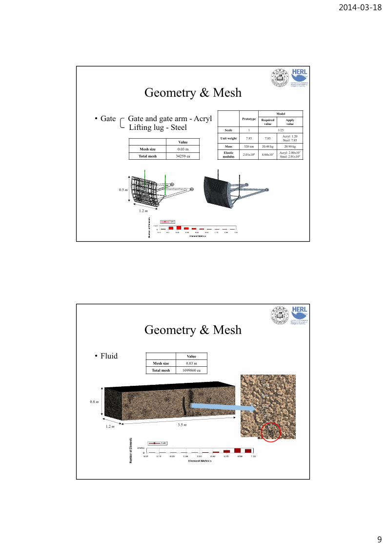
Initial & Boundary Conditions
Inlet Outlet Height of gate opening
Variable hi ho h
Value(m) 0.32 0.11 0.01, 0.04, 0.08
Type Condition
Inlet Opening Hydraulic Pressure
Outlet Opening Hydraulic Pressure
Top Opening Atmospheric pressure
Bottom Wall No-slip
Wall Wall No-slip
Gate Wall No-slip(Multifield)
0.32 m 0.11 m
Opening
OutletFluid-Solid
InterfaceWall
Inlet
Bottom
• Initial conditions • Boundary conditions
Initial & Boundary Conditions
• Restriction conditions
• Simulation cases
R1 R2C1
Displacement
X Component Y Component Z Component
R1 Free Constant Constant
R2 Constant Constant Free
Cylindrical Support
Radial Axial Tangential
C1 Fixed Fixed Free
Height of gate opening (m) Discharge(m3/s) Simulation times(s)
0.01 = 0.0261
100.04 = 0.0939
0.08 = 0.1669

2014-03-18
11
Results
• Vibration of gate
Fast Fouier Transform
Distribution of frequency has the same tendency with experimental results. When height of opening gate is 0.08 m, vibration is the max value.
DispalcementHeight of opening gate, h
0.01 0.04 0.08
Max(m) 0.81×10⁹ 0.68×10⁹ 2.67×10⁹
Min(m) -1.26×10⁹ -0.94×10⁹ 2.04×10⁹
Value(m) 2.06×10⁹ 1.62×10⁹ 4.71×10⁹
Results
• Analysis of amplitudeHeight of
opening gate(m)Experiment Numerical
Vertical amplitude(m) Vertical amplitude(m) Horizontal amplitude(m)
0.01 5.4×10⁻⁶ 7.96×10⁻⁶ 2.44×10⁻⁴
0.04 2.7×10⁻⁶ 6.81×10⁻⁶ 0.79×10⁻⁴
0.08 32×10-6 37.66×10⁻⁶ 2.47×10⁻⁴
Results of vibration analysis in numerical experiment have the same tendency with the experimental results.At the height of opening gate is 0.08 m, max value of amplitude occurs.
Peak

2014-03-18
12
Results
• Vibration in flow direction
• Analysis of frequency
Vibration experiment was performed only on the vertical vibration in experiment. However, vibration in flow direction is more important than that in vertical direction.
Height ofopening gate(m)
Frequency(Hz)
Experiment Numerical
0.01 16.7 15.0
0.04 14.5 13.9
0.08 13.5 12.8
Results
• Sturture Analysis
Max ValueHeight of opening gate(m)
0.01 0.04 0.08
Total displacement X(m) 4.826×10⁻⁵ 4.521×10⁻⁵ 3.984×10⁻⁵
Total displacement Z(m) 3.173×10⁻⁸ 3.014×10⁻⁸ 2.807×10⁻⁸
Stress intensity 5.431×10⁻⁶ 5.644×10⁻⁶ 5.644×10⁻⁶

2014-03-18
13
Conclusion and Future works
• Conclusion- Techniques of FSI analysis can be applied to vibration analysis.- Displacement and amplitude are much affected by the vibration
in flow direction rather than that in vertical.- In the structure analysis, maximum stress is concentrated at
lifting lug.
• Future works- Identify the case in according to the frequency change to prevent
serious damage caused by the resonance.- Vibration analysis using the General Moving Object(GMO) in
the operation of the gate in the field.
Floating Type Photovoltaic Composite Structure

2014-03-18
14
Floating Type Photovoltaic Composite Structure
• IntroductionThe floating type photovoltaic composite structure is a structure that enables power generation in reservoir and coast.
• PurposeExamine of displacement and stress according to variation of wave height.
※Floating type photovoltaic composite structure
Assumption
• Solar cell module is not stressed.Examine the safety of floating structure using only upper frame.
• Wind-induced wave is assumed as linear wave - Wave height(): = cos − - X-direction velocity(): = () cos( − )- Z-direction velocity(): = () sin( − )
Where, : amplitude, : wave number, : circular frequency: horizontal displacement, : time

2014-03-18
15
Geometry
Composed of upper frame, connector and lower floating structure.
• Upper frame- Composed of FRP(The strength of FRP is similar to that of steel but
its density is about a quarter of steel.)- 2 Unit was connected with 4 connecting hinge.
FRP(Fiber Reinforced Plastics) Upper FrameDensity(kg/m3) Young’s Modulus(GPa)
Allowable Stress(MPa) Mass(kg)
Volume(m3)Tensile Compressive Shear Bending
1900.00 33.28 231.76 154.50 26.37 185.40 859.78 0.45252
Geometry
• Connector- Shape made by bending a steel plate- Convert to 0.01 m for minimum material thickness- Convert to the solid shape from plate material and the density to be
the same weight in order to improve the convergence of calculation
Steel Unit connectorOriginalDensity(kg/m3)
ConvertedDensity(kg/m3)
Young’s Modulus(GPa)
Allowable Stress(MPa) Mass(kg)
Volume(m3)Tensile Compressive
7,850 954.55 200 102.50 80.00 3.2565 0.00341

2014-03-18
16
Geometry
• Lower floating structure- Composed of styrofoam- Fluid solid interface in FSI simulation
Styrofoam Lower floating structure
Density(kg/m3) Young’s Modulus(GPa) Mass(kg) Volume(m3)
70.00 2.25 34.789 0.497
Fluid solid interface
Mesh
Mesh of structure and fluid was composed of tetrahedron mesh(Minimum size = 0.01 m).
• Fluid
• Structure

2014-03-18
17
Boundary condition
• Fluid
• Structure
Initial condition
• Wind velocity condition : 30 m/s and 45 m/s※ 45 m/s is design wind velocity for dam and reservoir in Korea.
• Wind-induced wave height was calculated by Moliter’s equation.ℎ = 0.06 ⁄ + 0.76 − 0.27
Where, ℎ: wave height(m), : wind velocity(m/s), : fetch(the length of water over which a given wind has blown)
Case Wind velocity(m/s) Wave height(m) Period(sec) Wave length(m)
Case 1 45 1.256 4 24.9724
Case 2 30 1.091 4 24.9724
<Table> Inlet condition

2014-03-18
18
Results
• Simulation movie (Case 1, Wind velocity = 45 m/s)- The floating structure moves up and down by wave
propagation.- The stress distribution occurred from the movement.
Results
• Case 1(Wind velocity = 45 m/s)- Stress
t/TPrincipal Stress 1(MPa) Principal Stress 3(MPa) Von Mises Stress(MPa)Max. Min. Max. Min. Max.
0.00 5.90 -0.28 8.30 -0.25 8.920.10 13.32 -0.40 10.59 -0.61 12.300.20 15.08 -0.88 25.53 -1.51 23.600.25 15.45 -0.93 27.20 -1.60 25.130.30 16.54 -0.87 24.90 -1.51 23.020.35 17.30 -0.83 22.84 -1.40 21.120.40 14.45 -0.70 19.04 -1.18 17.610.50 2.81 -0.19 3.95 -0.24 4.150.60 14.96 -0.79 17.04 -0.62 18.600.70 16.70 -0.98 22.09 -0.81 23.620.75 16.20 -0.96 22.24 -0.81 23.480.80 14.52 -0.87 20.59 -0.75 21.580.90 8.57 -0.58 15.02 -0.51 16.211.00 1.77 -0.21 6.00 -0.27 6.45

2014-03-18
19
Results
• Case 1- Stress(○ : Maximum value)
üMaximum tensile stress occurred at 0.35 T.üMaximum compressive and equivalent stress occurred at 0.25 T.
Principal Stress 1(Tensile)
0.35
Von Mises Stress 1(Equivalent)Principal Stress 3(Compressive)
Results
• Case 1- Vertical location by variation of phase
üLarger stress occurred when the number of supports was smaller(0.25T, 0.75T).
üMinimum stress occurred when the position of connecting hinge was the highest and lowest(0.50T, 1.00T).
0.75 T(3 supports) 1.00 T(6 supports)
0.25 T(3 supports) 0.50 T(6 supports)
: support by wave

2014-03-18
20
Results
• Case 1- Location of maximum Stress by variation of phase
üMaximum stress position is connecting point between connector and upper frame.
0.75 T 1.00 T
0.25 T 0.50 T0.35 T
+ : tensile+ : compressive• : equivalent
Results
• Case 2(Wind velocity = 30 m/s)- Stress
t/TPrincipal Stress 1(MPa) Principal Stress 3(MPa) Von Mises Stress(MPa)Max. Min. Max. Min. Max.
0.00 4.65 -0.27 7.69 -0.22 8.31 0.10 12.29 -0.39 11.66 -0.65 11.40 0.20 13.73 -0.81 23.59 -1.38 21.81 0.25 14.53 -0.85 24.20 -1.45 22.37 0.30 14.87 -0.80 22.53 -1.37 20.83 0.35 14.53 -0.74 20.22 -1.25 18.70 0.40 11.51 -0.59 15.91 -0.99 14.72 0.50 3.19 -0.22 4.67 -0.24 4.98 0.60 13.17 -0.73 15.71 -0.58 17.15 0.70 14.92 -0.90 20.36 -0.74 21.58 0.75 14.28 -0.87 20.20 -0.73 21.33 0.80 12.54 -0.79 18.49 -0.67 19.40 0.90 6.34 -0.49 12.78 -0.43 13.80 1.00 1.89 -0.17 4.53 -0.31 4.77

2014-03-18
21
Results
• Case 2- Stress(○ : Maximum value)
üMaximum tensile stress occurred at 0.70 T.üMaximum compressive and equivalent stress occurred at 0.25 T.üTendency of Case 2 was similar to Case 1.
Principal Stress 1(Tensile)
0.70
Von Mises Stress 1(Equivalent)Principal Stress 3(Compressive)
Results
• Case 2- Vertical location by variation of phase
0.25 T(3 supports) 0.50 T(6 supports)
0.75 T(3 supports) 1.00 T(6 supports)
: support by wave

2014-03-18
22
Results
• Case 2- Location of maximum Stress by variation of phase
üMaximum stress position is connecting point between connector and upper frame.
+ : tensile+ : compressive• : equivalent
0.25 T 0.50 T 0.70 T
0.75 T 1.00 T
Results
• Comparison between cases - Maximum stress
ü Stresses at Case 1 averagely occurred 7.9~9.5% lager than at Case 2.
Principal Stress 1(Tensile) Principal Stress 3(Compressive) Von Mises Stress 1(Equivalent)
2014-03-18
23
Conclusion and Future works
• Conclusion- Maximum stress value increases as the wave height is large.Ø Wave height increases from 1.091 m to 1.256 m, Maximum stress
increases 7.9~9.5 %.- Minimum stress occurred when the position of connecting
hinge joint was the highest and lowest.- Maximum stress position is connecting point between
connector and upper frame.
• Future works- Analysis including solar cell- Analysis of floating structure in flow- Evaluating safety of connecting hinge joint
Conclusion

2014-03-18
24
Conclusion
• In case of the vibration of gate opening, numerical results are similar to them from hydraulic experiments.⇒ The applicability of FSI was confirmed.• Analysis of Multiphase flow and Dynamical behavior of structures
are conducted simultaneously with FSI method. Therefore, the applicability of FSI can be extended overall, however, simulation time excessively increase and higher performance of hardware is needed.⇒ Consideration of efficiency and cost-effectiveness is required.• Fully coupled analysis may not available with ANSYS-CFD.⇒ Until now, FSI method is utilized qualitatively in the limited
field.
Reference
• ANSYS, Inc., (1994). “Theory Reference Release 5.6”.• Benra F.K, (2011). “A Comparison of One-Way and Two-Way Coupling
Methods for Numerical Analysis of Fluid-Structure Interactions.”, Journal of Applied Mathematics.
• Notre Dame Univ., (2011). “Computational Fluid Dynamics”, CFD-Course.
• Jong Chull Jo, (2004). “Fluid-Structure Interactions”, fluid-structure interactions.
• Janez Gale, (2008). “Fluid-Structure Interaction for simulations of fast transients”, Doctoral thesis.
• Thomas Richter, (2010). “Numerical Methods for Fluid-Structure Interaction Problems”, Heidelberg Univ.
• Cirak F, (2009) “International Workshop on Fluid-Structure Interaction.”, Kassel Univ.

2014-03-18
25
Thank you for your attention.Q & A