Embed Size (px)
Citation preview
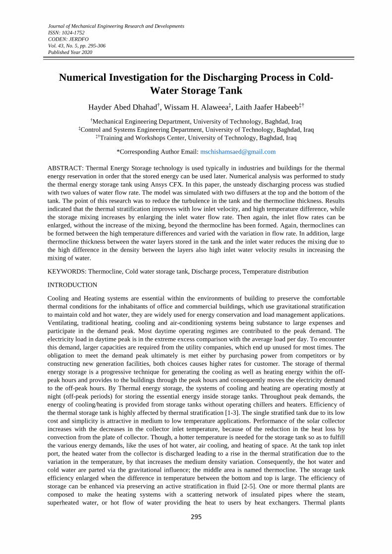
Journal of Mechanical Engineering Research and Developments
ISSN: 1024-1752
CODEN: JERDFO
Vol. 43, No. 5, pp. 295-306
Published Year 2020
295
Numerical Investigation for the Discharging Process in Cold-
Water Storage Tank
Hayder Abed Dhahad†, Wissam H. Alaweea‡, Laith Jaafer Habeeb‡†
†Mechanical Engineering Department, University of Technology, Baghdad, Iraq ‡Control and Systems Engineering Department, University of Technology, Baghdad, Iraq
‡†Training and Workshops Center, University of Technology, Baghdad, Iraq
*Corresponding Author Email: [email protected]
ABSTRACT: Thermal Energy Storage technology is used typically in industries and buildings for the thermal
energy reservation in order that the stored energy can be used later. Numerical analysis was performed to study
the thermal energy storage tank using Ansys CFX. In this paper, the unsteady discharging process was studied
with two values of water flow rate. The model was simulated with two diffusers at the top and the bottom of the
tank. The point of this research was to reduce the turbulence in the tank and the thermocline thickness. Results
indicated that the thermal stratification improves with low inlet velocity, and high temperature difference, while
the storage mixing increases by enlarging the inlet water flow rate. Then again, the inlet flow rates can be
enlarged, without the increase of the mixing, beyond the thermocline has been formed. Again, thermoclines can
be formed between the high temperature differences and varied with the variation in flow rate. In addition, large
thermocline thickness between the water layers stored in the tank and the inlet water reduces the mixing due to
the high difference in the density between the layers also high inlet water velocity results in increasing the
mixing of water.
KEYWORDS: Thermocline, Cold water storage tank, Discharge process, Temperature distribution
INTRODUCTION
Cooling and Heating systems are essential within the environments of building to preserve the comfortable
thermal conditions for the inhabitants of office and commercial buildings, which use gravitational stratification
to maintain cold and hot water, they are widely used for energy conservation and load management applications.
Ventilating, traditional heating, cooling and air-conditioning systems being substance to large expenses and
participate in the demand peak. Most daytime operating regimes are contributed to the peak demand. The
electricity load in daytime peak is in the extreme excess comparison with the average load per day. To encounter
this demand, larger capacities are required from the utility companies, which end up unused for most times. The
obligation to meet the demand peak ultimately is met either by purchasing power from competitors or by
constructing new generation facilities, both choices causes higher rates for customer. The storage of thermal
energy storage is a progressive technique for generating the cooling as well as heating energy within the off-
peak hours and provides to the buildings through the peak hours and consequently moves the electricity demand
to the off-peak hours. By Thermal energy storage, the systems of cooling and heating are operating mostly at
night (off-peak periods) for storing the essential energy inside storage tanks. Throughout peak demands, the
energy of cooling/heating is provided from storage tanks without operating chillers and heaters. Efficiency of
the thermal storage tank is highly affected by thermal stratification [1-3]. The single stratified tank due to its low
cost and simplicity is attractive in medium to low temperature applications. Performance of the solar collector
increases with the decreases in the collector inlet temperature, because of the reduction in the heat loss by
convection from the plate of collector. Though, a hotter temperature is needed for the storage tank so as to fulfill
the various energy demands, like the uses of hot water, air cooling, and heating of space. At the tank top inlet
port, the heated water from the collector is discharged leading to a rise in the thermal stratification due to the
variation in the temperature, by that increases the medium density variation. Consequently, the hot water and
cold water are parted via the gravitational influence; the middle area is named thermocline. The storage tank
efficiency enlarged when the difference in temperature between the bottom and top is large. The efficiency of
storage can be enhanced via preserving an active stratification in fluid [2-5]. One or more thermal plants are
composed to make the heating systems with a scattering network of insulated pipes where the steam,
superheated water, or hot flow of water providing the heat to users by heat exchangers. Thermal plants
Numerical Investigation for the Discharging Process in Cold-Water Storage Tank
296
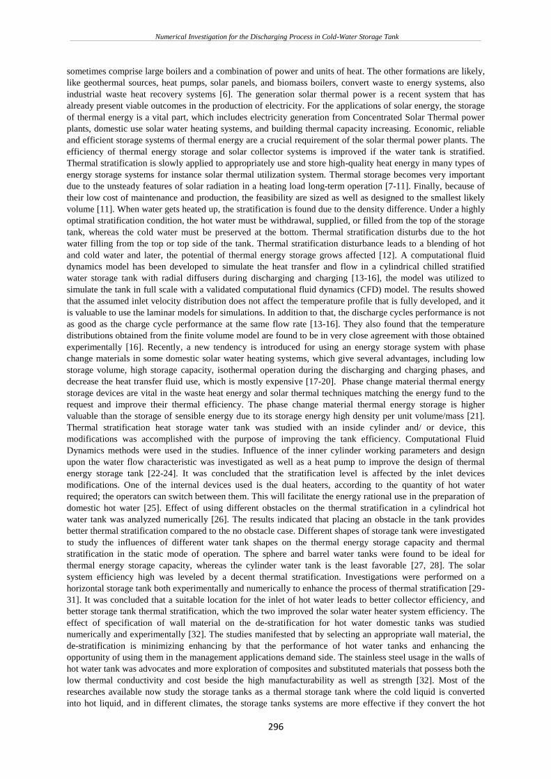
sometimes comprise large boilers and a combination of power and units of heat. The other formations are likely,
like geothermal sources, heat pumps, solar panels, and biomass boilers, convert waste to energy systems, also
industrial waste heat recovery systems [6]. The generation solar thermal power is a recent system that has
already present viable outcomes in the production of electricity. For the applications of solar energy, the storage
of thermal energy is a vital part, which includes electricity generation from Concentrated Solar Thermal power
plants, domestic use solar water heating systems, and building thermal capacity increasing. Economic, reliable
and efficient storage systems of thermal energy are a crucial requirement of the solar thermal power plants. The
efficiency of thermal energy storage and solar collector systems is improved if the water tank is stratified.
Thermal stratification is slowly applied to appropriately use and store high-quality heat energy in many types of
energy storage systems for instance solar thermal utilization system. Thermal storage becomes very important
due to the unsteady features of solar radiation in a heating load long-term operation [7-11]. Finally, because of
their low cost of maintenance and production, the feasibility are sized as well as designed to the smallest likely
volume [11]. When water gets heated up, the stratification is found due to the density difference. Under a highly
optimal stratification condition, the hot water must be withdrawal, supplied, or filled from the top of the storage
tank, whereas the cold water must be preserved at the bottom. Thermal stratification disturbs due to the hot
water filling from the top or top side of the tank. Thermal stratification disturbance leads to a blending of hot
and cold water and later, the potential of thermal energy storage grows affected [12]. A computational fluid
dynamics model has been developed to simulate the heat transfer and flow in a cylindrical chilled stratified
water storage tank with radial diffusers during discharging and charging [13-16], the model was utilized to
simulate the tank in full scale with a validated computational fluid dynamics (CFD) model. The results showed
that the assumed inlet velocity distribution does not affect the temperature profile that is fully developed, and it
is valuable to use the laminar models for simulations. In addition to that, the discharge cycles performance is not
as good as the charge cycle performance at the same flow rate [13-16]. They also found that the temperature
distributions obtained from the finite volume model are found to be in very close agreement with those obtained
experimentally [16]. Recently, a new tendency is introduced for using an energy storage system with phase
change materials in some domestic solar water heating systems, which give several advantages, including low
storage volume, high storage capacity, isothermal operation during the discharging and charging phases, and
decrease the heat transfer fluid use, which is mostly expensive [17-20]. Phase change material thermal energy
storage devices are vital in the waste heat energy and solar thermal techniques matching the energy fund to the
request and improve their thermal efficiency. The phase change material thermal energy storage is higher
valuable than the storage of sensible energy due to its storage energy high density per unit volume/mass [21].
Thermal stratification heat storage water tank was studied with an inside cylinder and/ or device, this
modifications was accomplished with the purpose of improving the tank efficiency. Computational Fluid
Dynamics methods were used in the studies. Influence of the inner cylinder working parameters and design
upon the water flow characteristic was investigated as well as a heat pump to improve the design of thermal
energy storage tank [22-24]. It was concluded that the stratification level is affected by the inlet devices
modifications. One of the internal devices used is the dual heaters, according to the quantity of hot water
required; the operators can switch between them. This will facilitate the energy rational use in the preparation of
domestic hot water [25]. Effect of using different obstacles on the thermal stratification in a cylindrical hot
water tank was analyzed numerically [26]. The results indicated that placing an obstacle in the tank provides
better thermal stratification compared to the no obstacle case. Different shapes of storage tank were investigated
to study the influences of different water tank shapes on the thermal energy storage capacity and thermal
stratification in the static mode of operation. The sphere and barrel water tanks were found to be ideal for
thermal energy storage capacity, whereas the cylinder water tank is the least favorable [27, 28]. The solar
system efficiency high was leveled by a decent thermal stratification. Investigations were performed on a
horizontal storage tank both experimentally and numerically to enhance the process of thermal stratification [29-
31]. It was concluded that a suitable location for the inlet of hot water leads to better collector efficiency, and
better storage tank thermal stratification, which the two improved the solar water heater system efficiency. The
effect of specification of wall material on the de-stratification for hot water domestic tanks was studied
numerically and experimentally [32]. The studies manifested that by selecting an appropriate wall material, the
de-stratification is minimizing enhancing by that the performance of hot water tanks and enhancing the
opportunity of using them in the management applications demand side. The stainless steel usage in the walls of
hot water tank was advocates and more exploration of composites and substituted materials that possess both the
low thermal conductivity and cost beside the high manufacturability as well as strength [32]. Most of the
researches available now study the storage tanks as a thermal storage tank where the cold liquid is converted
into hot liquid, and in different climates, the storage tanks systems are more effective if they convert the hot
Numerical Investigation for the Discharging Process in Cold-Water Storage Tank
297
liquid into a cold one. This paper numerically studies the storage tank discharging process where the hot water is
converted into a cold water at 4⁰C to be used during the peak hours.
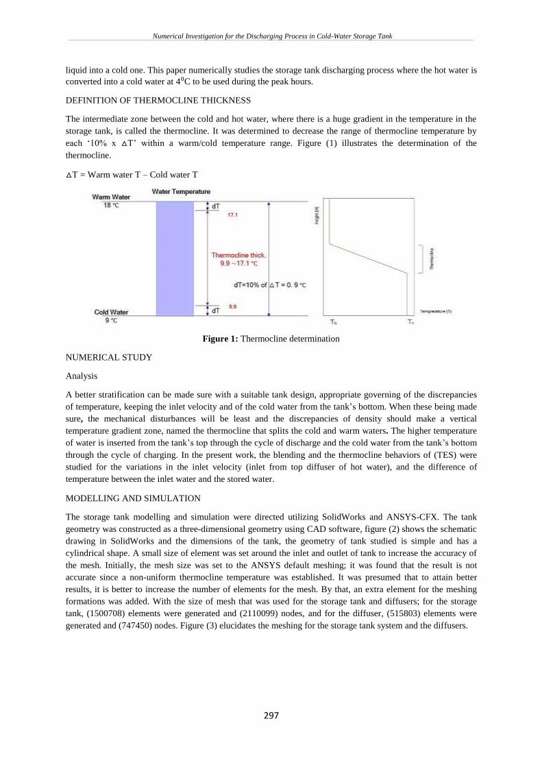
DEFINITION OF THERMOCLINE THICKNESS
The intermediate zone between the cold and hot water, where there is a huge gradient in the temperature in the
storage tank, is called the thermocline. It was determined to decrease the range of thermocline temperature by
each ‘10% x △T’ within a warm/cold temperature range. Figure (1) illustrates the determination of the
thermocline.
△T = Warm water T – Cold water T
Figure 1: Thermocline determination
NUMERICAL STUDY
Analysis
A better stratification can be made sure with a suitable tank design, appropriate governing of the discrepancies
of temperature, keeping the inlet velocity and of the cold water from the tank’s bottom. When these being made
sure, the mechanical disturbances will be least and the discrepancies of density should make a vertical
temperature gradient zone, named the thermocline that splits the cold and warm waters. The higher temperature
of water is inserted from the tank’s top through the cycle of discharge and the cold water from the tank’s bottom
through the cycle of charging. In the present work, the blending and the thermocline behaviors of (TES) were
studied for the variations in the inlet velocity (inlet from top diffuser of hot water), and the difference of
temperature between the inlet water and the stored water.
MODELLING AND SIMULATION
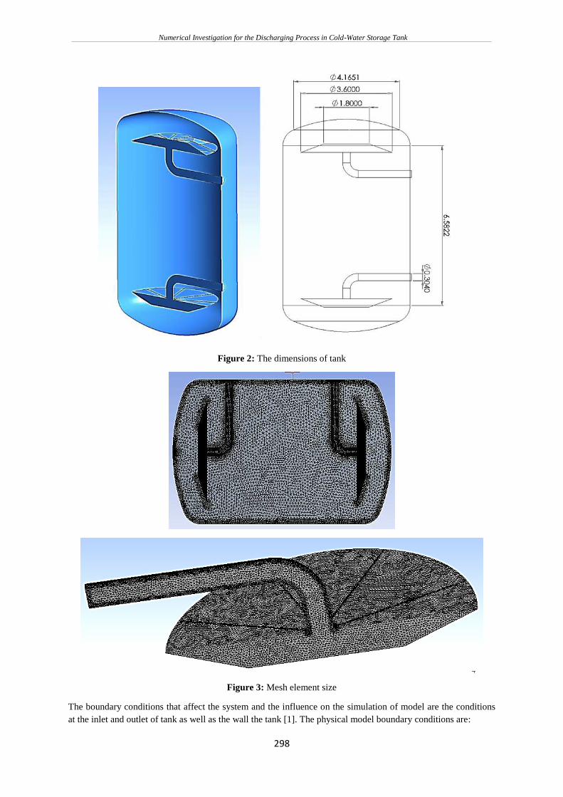
The storage tank modelling and simulation were directed utilizing SolidWorks and ANSYS-CFX. The tank
geometry was constructed as a three-dimensional geometry using CAD software, figure (2) shows the schematic
drawing in SolidWorks and the dimensions of the tank, the geometry of tank studied is simple and has a
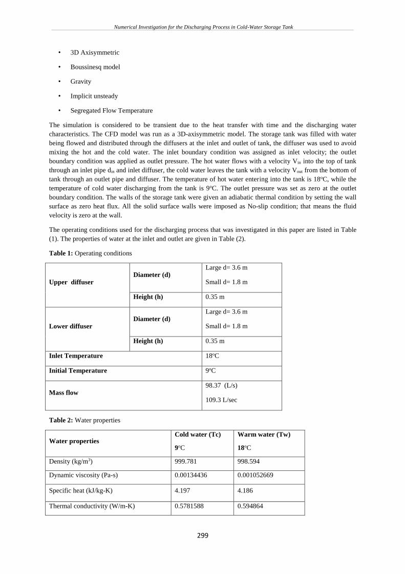
cylindrical shape. A small size of element was set around the inlet and outlet of tank to increase the accuracy of
the mesh. Initially, the mesh size was set to the ANSYS default meshing; it was found that the result is not
accurate since a non-uniform thermocline temperature was established. It was presumed that to attain better
results, it is better to increase the number of elements for the mesh. By that, an extra element for the meshing
formations was added. With the size of mesh that was used for the storage tank and diffusers; for the storage
tank, (1500708) elements were generated and (2110099) nodes, and for the diffuser, (515803) elements were
generated and (747450) nodes. Figure (3) elucidates the meshing for the storage tank system and the diffusers.
Numerical Investigation for the Discharging Process in Cold-Water Storage Tank
298
Figure 2: The dimensions of tank
Figure 3: Mesh element size
The boundary conditions that affect the system and the influence on the simulation of model are the conditions
at the inlet and outlet of tank as well as the wall the tank [1]. The physical model boundary conditions are:
Numerical Investigation for the Discharging Process in Cold-Water Storage Tank
299
• 3D Axisymmetric
• Boussinesq model
• Gravity
• Implicit unsteady
• Segregated Flow Temperature
The simulation is considered to be transient due to the heat transfer with time and the discharging water
characteristics. The CFD model was run as a 3D-axisymmetric model. The storage tank was filled with water
being flowed and distributed through the diffusers at the inlet and outlet of tank, the diffuser was used to avoid
mixing the hot and the cold water. The inlet boundary condition was assigned as inlet velocity; the outlet
boundary condition was applied as outlet pressure. The hot water flows with a velocity Vin into the top of tank
through an inlet pipe din and inlet diffuser, the cold water leaves the tank with a velocity Vout from the bottom of
tank through an outlet pipe and diffuser. The temperature of hot water entering into the tank is 18oC, while the
temperature of cold water discharging from the tank is 9oC. The outlet pressure was set as zero at the outlet
boundary condition. The walls of the storage tank were given an adiabatic thermal condition by setting the wall
surface as zero heat flux. All the solid surface walls were imposed as No-slip condition; that means the fluid
velocity is zero at the wall.
The operating conditions used for the discharging process that was investigated in this paper are listed in Table
(1). The properties of water at the inlet and outlet are given in Table (2).
Table 1: Operating conditions
Upper diffuser Diameter (d)
Large d= 3.6 m
Small d= 1.8 m
Height (h) 0.35 m
Lower diffuser Diameter (d)
Large d= 3.6 m
Small d= 1.8 m
Height (h) 0.35 m
Inlet Temperature 18oC
Initial Temperature 9oC
Mass flow 98.37 (L/s)
109.3 L/sec
Table 2: Water properties
Water properties Cold water (Tc)
9oC
Warm water (Tw)
18oC
Density (kg/m3) 999.781 998.594
Dynamic viscosity (Pa-s) 0.00134436 0.001052669
Specific heat (kJ/kg-K) 4.197 4.186
Thermal conductivity (W/m-K) 0.5781588 0.594864
Numerical Investigation for the Discharging Process in Cold-Water Storage Tank
300
Thermal expansion coefficient (1/K) 0.003544 0.003436
The governing transport expressions for the continuity, the momentum and the energy conservation for a fluid
are [1]:
- For continuity:
( ). 0ut
+ =
(1)
- For momentum:
( )( )
. . M
uu u S
t
+ = − + +
(2)
- For energy:
( )( )
. .( ) : M
hu h T u S
t
+ = + +
(3)
RESULTS AND DISCUSSION
This paper simulates the discharging process, which starts after completing the charging process. In this method,
cold water is discharged from the thermal energy storage tank, and the same amount of hot water at 18oC is fed
into the storage tank at the same time. CFD is concerned with obtaining a numerical solution to the fluid flow
problems by using computers [18]. Modeling of water density was made. It states that the difference in the
density is small sufficiently to be neglected, it performs in terms multiplied by the acceleration caused by
Gravitational acceleration (g). So, the density was evaluated only in momentum equations in the simulation of
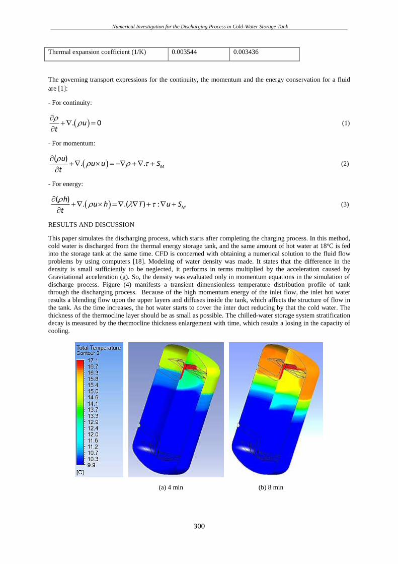
discharge process. Figure (4) manifests a transient dimensionless temperature distribution profile of tank
through the discharging process. Because of the high momentum energy of the inlet flow, the inlet hot water
results a blending flow upon the upper layers and diffuses inside the tank, which affects the structure of flow in
the tank. As the time increases, the hot water starts to cover the inter duct reducing by that the cold water. The
thickness of the thermocline layer should be as small as possible. The chilled-water storage system stratification
decay is measured by the thermocline thickness enlargement with time, which results a losing in the capacity of
cooling.
(a) 4 min (b) 8 min
Numerical Investigation for the Discharging Process in Cold-Water Storage Tank
301
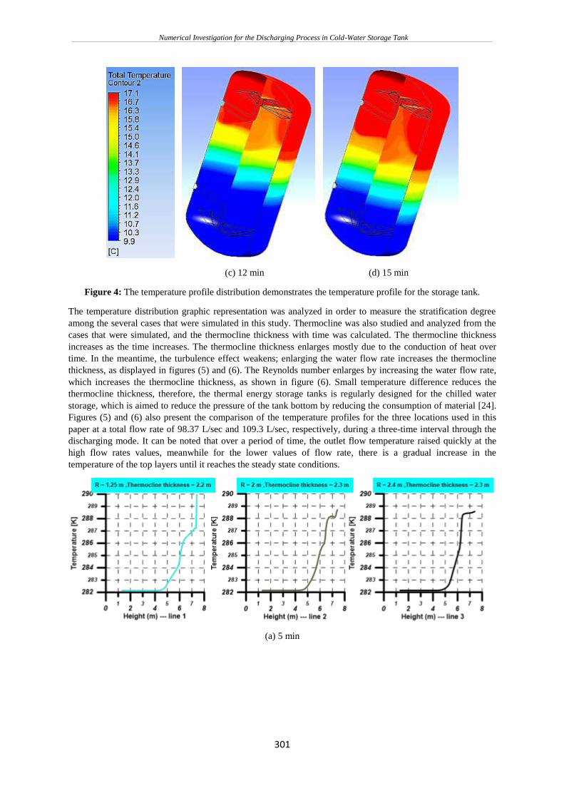
(c) 12 min (d) 15 min
Figure 4: The temperature profile distribution demonstrates the temperature profile for the storage tank.
The temperature distribution graphic representation was analyzed in order to measure the stratification degree
among the several cases that were simulated in this study. Thermocline was also studied and analyzed from the
cases that were simulated, and the thermocline thickness with time was calculated. The thermocline thickness
increases as the time increases. The thermocline thickness enlarges mostly due to the conduction of heat over
time. In the meantime, the turbulence effect weakens; enlarging the water flow rate increases the thermocline
thickness, as displayed in figures (5) and (6). The Reynolds number enlarges by increasing the water flow rate,
which increases the thermocline thickness, as shown in figure (6). Small temperature difference reduces the
thermocline thickness, therefore, the thermal energy storage tanks is regularly designed for the chilled water
storage, which is aimed to reduce the pressure of the tank bottom by reducing the consumption of material [24].
Figures (5) and (6) also present the comparison of the temperature profiles for the three locations used in this
paper at a total flow rate of 98.37 L/sec and 109.3 L/sec, respectively, during a three-time interval through the
discharging mode. It can be noted that over a period of time, the outlet flow temperature raised quickly at the
high flow rates values, meanwhile for the lower values of flow rate, there is a gradual increase in the
temperature of the top layers until it reaches the steady state conditions.
(a) 5 min
Numerical Investigation for the Discharging Process in Cold-Water Storage Tank
302
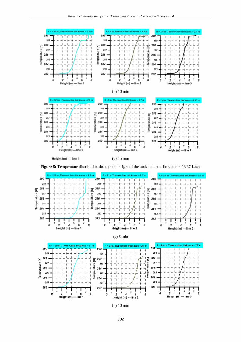
(b) 10 min
(c) 15 min
Figure 5: Temperature distribution through the height of the tank at a total flow rate = 98.37 L/sec
(a) 5 min
(b) 10 min
Numerical Investigation for the Discharging Process in Cold-Water Storage Tank
303
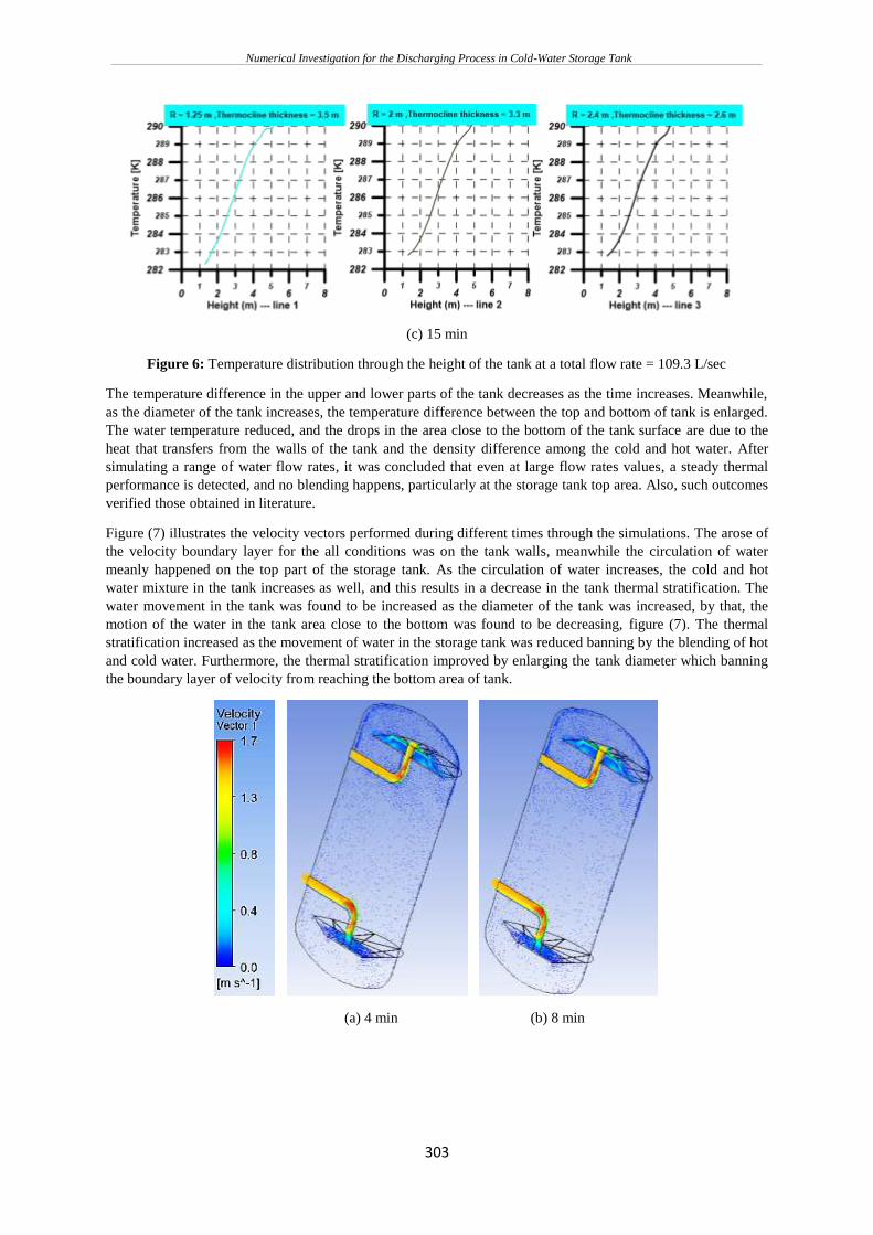
(c) 15 min
Figure 6: Temperature distribution through the height of the tank at a total flow rate = 109.3 L/sec
The temperature difference in the upper and lower parts of the tank decreases as the time increases. Meanwhile,
as the diameter of the tank increases, the temperature difference between the top and bottom of tank is enlarged.
The water temperature reduced, and the drops in the area close to the bottom of the tank surface are due to the
heat that transfers from the walls of the tank and the density difference among the cold and hot water. After
simulating a range of water flow rates, it was concluded that even at large flow rates values, a steady thermal
performance is detected, and no blending happens, particularly at the storage tank top area. Also, such outcomes
verified those obtained in literature.
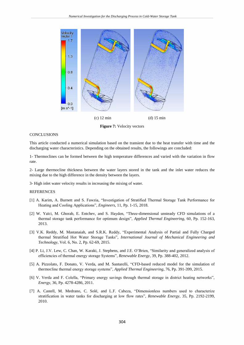
Figure (7) illustrates the velocity vectors performed during different times through the simulations. The arose of
the velocity boundary layer for the all conditions was on the tank walls, meanwhile the circulation of water
meanly happened on the top part of the storage tank. As the circulation of water increases, the cold and hot
water mixture in the tank increases as well, and this results in a decrease in the tank thermal stratification. The
water movement in the tank was found to be increased as the diameter of the tank was increased, by that, the
motion of the water in the tank area close to the bottom was found to be decreasing, figure (7). The thermal
stratification increased as the movement of water in the storage tank was reduced banning by the blending of hot
and cold water. Furthermore, the thermal stratification improved by enlarging the tank diameter which banning
the boundary layer of velocity from reaching the bottom area of tank.
(a) 4 min (b) 8 min
Numerical Investigation for the Discharging Process in Cold-Water Storage Tank
304
(c) 12 min (d) 15 min
Figure 7: Velocity vectors
CONCLUSIONS
This article conducted a numerical simulation based on the transient due to the heat transfer with time and the
discharging water characteristics. Depending on the obtained results, the followings are concluded:
1- Thermoclines can be formed between the high temperature differences and varied with the variation in flow
rate.
2- Large thermocline thickness between the water layers stored in the tank and the inlet water reduces the
mixing due to the high difference in the density between the layers.
3- High inlet water velocity results in increasing the mixing of water.
REFERENCES
[1] A. Karim, A. Burnett and S. Fawzia, “Investigation of Stratified Thermal Storage Tank Performance for
Heating and Cooling Applications”, Engineers, 11, Pp. 1-15, 2018.
[2] W. Yaïci, M. Ghorab, E. Entchev, and S. Hayden, “Three-dimensional unsteady CFD simulations of a
thermal storage tank performance for optimum design”, Applied Thermal Engineering, 60, Pp. 152-163,
2013.
[3] V.K. Reddy, M. Mastanaiah, and S.R.K. Reddy, “Experimental Analysis of Partial and Fully Charged
thermal Stratified Hot Water Storage Tanks”, International Journal of Mechanical Engineering and
Technology, Vol. 6, No. 2, Pp. 62-69, 2015.
[4] P. Li, J.V. Lew, C. Chan, W. Karaki, J. Stephens, and J.E. O’Brien, “Similarity and generalized analysis of
efficiencies of thermal energy storage Systems”, Renewable Energy, 39, Pp. 388-402, 2012.
[5] A. Pizzolato, F. Donato, V. Verda, and M. Santarelli, “CFD-based reduced model for the simulation of
thermocline thermal energy storage systems”, Applied Thermal Engineering, 76, Pp. 391-399, 2015.
[6] V. Verda and F. Colella, “Primary energy savings through thermal storage in district heating networks”,
Energy, 36, Pp. 4278-4286, 2011.
[7] A. Castell, M. Medrano, C. Solé, and L.F. Cabeza, “Dimensionless numbers used to characterize
stratification in water tanks for discharging at low flow rates”, Renewable Energy, 35, Pp. 2192-2199,
2010.
Numerical Investigation for the Discharging Process in Cold-Water Storage Tank
305
[8] E. Andersen, S. Furbo, M. Hampel, W. Heidemann, and H. Muller-Steinhagen, “Investigations on
stratification devices for hot water heat stores”, International Journal of Energy Research, 32, Pp. 255–
263, 2008.
[9] Y.M. Han, R.Z. Wang, and Y.J. Dai, “Thermal stratification within the water tank”, Renewable and
Sustainable Energy Reviews, 13, Pp. 1014–1026, 2009.
[10] S. Pintaldi, C. Perfumo, S. Sethuvenkatraman, S. White, and G. Rosengarten, “A review of thermal energy
storage technologies and control Approaches for solar cooling”, Renewable and Sustainable Energy
Reviews, 41, Pp. 975–995, 2015.
[11] M. Tesfay and M. Venkatesan, “Simulation of thermocline thermal energy storage system using C”,
International Journal of Innovation and Applied Studies, Vol. 3, No. 2, Pp. 354-364, 2013.
[12] M. Bhaumik, “CFD simulation of inlet position of hot water into SDHW thermal storage tank”,
International Journal of Engineering and Technical Research (IJETR), Vol. 2, No. 4, Pp. 64-67, 2014.
[13] A. Musser, and W.P. Bahnfleth, “Parametric Study of Charging Inlet Diffuser Performance in Stratified
Chilled Water Storage Tanks with Radial Diffusers: Part 1–Model Development and Validation”, HVAC &
R Research, Vol. 7, No. 1 (2001), Pp. 31-50, 2001.
[14] W.P. Bahnfleth, and A. Musser, “Thermal Performance of a Full-Scale Stratified Chilled-Water Thermal
Storage Tank”, the American Society of Heating, Refrigerating and Air-Conditioning Engineers, Vol. 104,
1998.
[15] J. Song, W.P. Bahnfleth, and J.M. Cimbala, “Parametric Study of Single-Pipe Diffusers in Stratified
Chilled Water Storage Tanks (RP-1185)”, HVAC&R Research, Vol. 10, No. 3, Pp. 345-365, 2004.
[16] F.M. Hasan, and M.A. Theeb, “Experimental and Numerical Study of Heat Transfer Process of Chilled
Water Storage Tank”, Universal Journal of Mechanical Engineering, Vol. 6, No. 4 (2018) , Pp. 63-75,
2018.
[17] B. Xu, P. Li, C. Chan, and E. Tumilowicz, “General volume sizing strategy for thermal storage system for
concentrated solar thermal power plant”, Applied Energy, 140, Pp. 256–268, 2015.
[18] G.C. Naidu, K. Aruna, K.D. Reddy, and P.V. Ramaiah, “CFD Simulation for Charging and Discharging
Process of Thermal Energy Storage System using Phase Change Material”, International Journal of
Engineering Research, Vol. No.5, Pp. 332-339, 2016.
[19] P. Verma, Varun, and S.K. Singal, “Review of mathematical modeling on latent heat thermal energy
storage systems using phase change material”, Renewable and Sustainable Energy Reviews, 12, Pp. 999–
1031, 2008.
[20] M.H. Abokersh, M. Osman, O. El-Baz, M. El-Morsi, and O. Sharaf, “Review of the phase change material
(PCM) usage for solar domestic water heating systems (SDWHS)”, International Journal of Energy
Research, Pp. 42, Pp. 329–357, 2018.
[21] M.K.A. Sharif, A.A. Al-Abidi, S. Mat, K. Sopian, M.H. Ruslan, M.Y. Sulaiman, and M.A.M. Rosli,
“Review of the application of phase change material for heating and domestic hot water systems”,
Renewable and Sustainable Energy Reviews, 42, Pp. 557–568, 2015.
[22] I.J. Moncho-Esteve, M. Gasque, P. Gonz´alez-Altozano, and G. Palau-Salvador, “Simple inlet devices and
their influence on thermal stratification in a hot water storage tank”, Energy and Buildings,
http://dx.doi.org/10.1016/j.enbuild.2017.06.012.
[23] L. Kong, W. Yuan, and N. Zhu, “CFD simulations of thermal stratification heat storage water tank with an
inside cylinder with openings”, Procedia Engineering, 146, Pp. 394 – 399, 2016.
[24] J. Sun, J. Hua, L. Fu, and S. Zhang, “Experimental Study of a Large Temperature Difference Thermal
Energy Storage Tank for Centeralized Heating Systems”, Thermal Science, Vol. 22, No. 1B, Pp. 613-621,
2018.
Numerical Investigation for the Discharging Process in Cold-Water Storage Tank
306
[25] I. Sezai, L.B.Y. Aldabbagh, U. Atikol, and H. Hacisevki, “Performance improvement by using dual heaters
in a storage-type domestic electric water-heater”, Applied Energy, 81, Pp. 291–305, 2005.
[26] N. Altuntop, M. Arslan, V. Ozceyhan, and M. Kanoglu, “Effect of obstacles on thermal stratification in hot
water storage tanks”, Applied Thermal Engineering, Vol. 25, Pp. 2285–2298, 2005.
[27] B. Kurşun, “Thermal stratification enhancement in cylindrical and rectangular hot water tanks with
truncated cone and pyramid shaped insulation geometry”, Solar Energy, 169, Pp. 512–525, 2018.
[28] Z. Yang, H. Chen, L. Wang, Y. Sheng, and Y. Wang, “Comparative study of the influences of different
water tank shapes on thermal energy storage capacity and thermal stratification”, Renewable Energy, 85,
Pp. 31-44, 2016.
[29] M.R. Assari, H.B. Tabrizi, and M. Savadkohy, “Numerical and experimental study of inlet-outlet locations
effect in horizontal storage tank of solar water heater”, Sustainable Energy Technologies and Assessments,
Vol. 25, Pp. 181–190.
[30] D.L. Savicki, H.A. Vielmo, and A. Krenzinger, “Three-dimensional analysis and investigation of the
thermal and hydrodynamic behaviors of cylindrical storage tanks”, Renewable Energy, Vol. 36, Pp. 1364-
1373, 2011.
[31] B. Kurşun, and K. Ökten, “Effect of rectangular hot water tank position and aspect ratio on thermal
stratification enhancement”, Renewable Energy, 2017, doi: 10.1016/j.renene.2017.10.013.
[32] P. Armstrong, D. Ager, I. Thompson, and M. McCulloch, “Improving the energy storage capability of hot
water tanks through wall material specification”, Energy, 78, Pp. 128-140, 2014.