Embed Size (px)
Citation preview
162
Ciência eNatura, Santa Maria, v. 37 n. 2 jun. 2015, p. 162−172
ISSN impressa: 0100-8307 ISSN on-line: 2179-460X
Numerical Investigation Of Nanofluids Flow and Heat Transfer in 90
Elbow With square Cross-Section
Ayoob Khosravi Farsani 1, Afshin Ahmadi Nodooshan 2
1. MS student in mechanical engineering, University of Shahrekord, Shahrekord
2. Assistant Professor of Mechanical Engineering, University of Shahrekord, Shahrekord
Abstract
In this article, forced convective heat transfer of nanofluid flow in a horizontal tube with a square cross-
section and 90-degree elbow under heat flux was investigated in a numerical method. The homogeneous
nanofluid of aluminum oxide and water (Al2O3) was used as the working fluid. For the numerical solution of
continuity, momentum and energy equations, the finite volume method was used. In this study, the effect of
Reynolds number and the solid volume fraction and the impact of the elbow on the flow field and the heat
transfer rate and pressure drop was investigated. The results were presented in the form of flow and temperature
contours and the Nusselt diagrams, which have a good relation with the experimental results, and showed that
by increasing the solid volume fraction and Reynolds number, the heat transfer in the elbow increases. Also the
concave surface from inside the tubes had a greater impact on heat transfer than the convex surface.
Keywords: laminar flow, nanofluid, elbow 90 degrees, square cross-section, heat transfer
163
1 INTRODUCTION
Undoubtedly, heat transfer is one of the most
important and most widely used part of
engineering science and its significance can be
multiplied with respect to the energy crisis and
the need for fuel savings. Low thermal
conductivity of conventional heat fluids such as
water, oils, … reduces the efficiency of heating
equipment, so nowadays the new technology of
nanotechnology has been able to help scientists
to introduce the high-capacity thermal
transmission systems called nanofluids.
According to '' the rule of higher thermal
conductivity of fluid compared to metal'', mixed
metal nanoparticles suspended in nanofluid for
increasing thermal conductivity of fluids and
energy saving has taken the focus of
nanomechanical studies.
Here among a lot of researches conducted on
this flows, we refer to several cases. Among the
first theory studies on the curved pipe, we can
point to Mr. Dean research in 1927 [1]. He
indicated that the flow dynamic in bends
depends on Dean dimensionless parameter,
which is in fact the ratio of inertial and
centrifugal forces to viscous force.
Enayet et al [2] achieved speed in a 90-
degrees elbow with square cross-section and
ratio of radius to the channel width of 7 by
Laser-Doppler. They drawn contour speed at
different angles of elbow in the pipe section, and
correspond to Reynolds, they provided average
speed, turbulence intensity and shear stress in
charts to predict the flow, and the results were
used as the basis for turbulence models and
computer software.
Mohammad Boutabaa et al [3] examined
three-dimensional numerical simulation of
secondary flows in developing flow and
Newtonian fluid and viscoelastic in a curved
duct of square cross-section. They conducted
simulation for three different Dean numbers and
using a discrete finite volume and an orthogonal
coordinate system, and showed that in both
Newtonian and non-Newtonian fluids, the size
and numbers of vortices depend on Dean
number, and by increasing the number, Dean
length of development is reduced. The viscosity
also affects on the secondary flow and the
vortices growth rate in viscoelastic fluid is more
than Newtonian fluid.
Taofik et al [4] in an experimental laboratory
studied the characteristics of two nanofluids,
Al2O3/water and CuO/water, in laminar flow in
a square cupric duct and concluded that there is
a significant increase of heat transfer in both
nanofluids compared to base fluid; however
CuO nanofluid showed better heat transfer than
Al2O3 nanofluid.
Sasmito et al [5] in their article examined the
numerical heat transfer by changing flow
geometry and/or by enhancing thermal
conductivity of the fluid. The purpose of this
article was increasing the heat transfer fluid by
simultaneous changing flow geometry and
nanofluid in the quadrilateral cross-section
pipes; and two nanofluids, i.e. water/Al2O3 and
water/CuO have been studied. And also the
amount of thermal conductivity from different
geometries, such as straight pipes, flat-spiral
pipe, cylindrical helix and bevel helical
compared, which in result the heat transfer from
flat-spiral geometry was more than others, as
well as increasing 1 percent of nanofluid
concentration led to a significant increase in heat
transfer, and increasing of the solid particles is
not recommended more than this amount.
Junhong Yang et al [6] experimentally
compared the laminar flow of nanofluid in the
curved and straight pipes and showed that in
the straight pipes, at higher Reynolds numbers
the particles concentration is high, while in the
curved pipes, at higher Reynolds numbers we
have lower concentration of the particles. It
seems that by increasing the Reynolds number,
the effect of bending in stability of suspended
particles is increased; it can be concluded that by
increasing the concentration of particles and
reducing the curvature we can keep fluid in the
higher Reynolds numbers.
Dongsheng et al [7] experimentally
investigated convective heat transfer of Al2 O3
nanofluid flow inside a straight pipe under
laminar flow and concluded that:
164
By using aluminum oxide nanoparticles in
laminar flow, the convective heat transfer is
increased and also the heat transfer is increased
with the increase of the Reynolds number.This
increase in heat transfer is significant especially
in the entrance region and decreases with
distance from the axis; and the length of thermal
developed region in nanofluid is more than the
base fluid, and it increases with the increase of
the particle concentration.Displacement of these
particles reduces the viscosity and reduces the
thickness of the thermal boundary layer which
causes increasing in convective heat transfer.
Alireza Akbari Nia et al [8] numerically
simulated the laminar flow of nanofluid inside
the horizontal pipe in three-dimensional state
with respect to the effects of two centrifugal
and buoyancy forces by using the finite-volume
method. The research results showed that
increasing solid nanoparticles volume has no
effect on the axial velocity and frictional drag
coefficient. Adding solid nanoparticles
increases fluid temperature; it hasn't significant
effects on secondary flow and also increases
heat transfer. Increasing Grashof number
increases secondary flow arised due to
buoyancy force; therefore it leads to disturb the
symmetry in the secondary velocity vectors and
temperature contours and reduces the Nusselt
number.
According to the literature, curved channels
with a quadrilateral cross-section often used in
energy facilities which are widely used in
industrial devices, such as turbomachinery,
cooling systems, air conditioning, heat
exchangers, etc. But little research has been
done in this regard; and since in these sections
the pressure drop and heat transfer are very
important, in this study we decided to examine
laminar flow in a 90-degrees elbow with a
quadrilateral cross- section.
2 Problem Statement
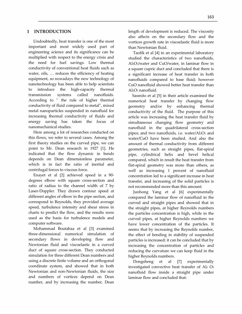
Figure 1 shows the computational region
including curved pipe with axial angle θ
between 0 and 90 degrees in the direction of
constant wall heat flux. The curvature angle of
the pipe is with a radius of 𝑅𝑐 and its
quadrilateral cross-section is to the side of h,
which in the pipe nanofluids of water and
aluminum oxide are flowing slowly and
continuously at the entrance with the speed of
v0 and constant temperature of T0 = 298k. In
this figure L=300 mm ،h=80mm and 𝑅𝑐 =
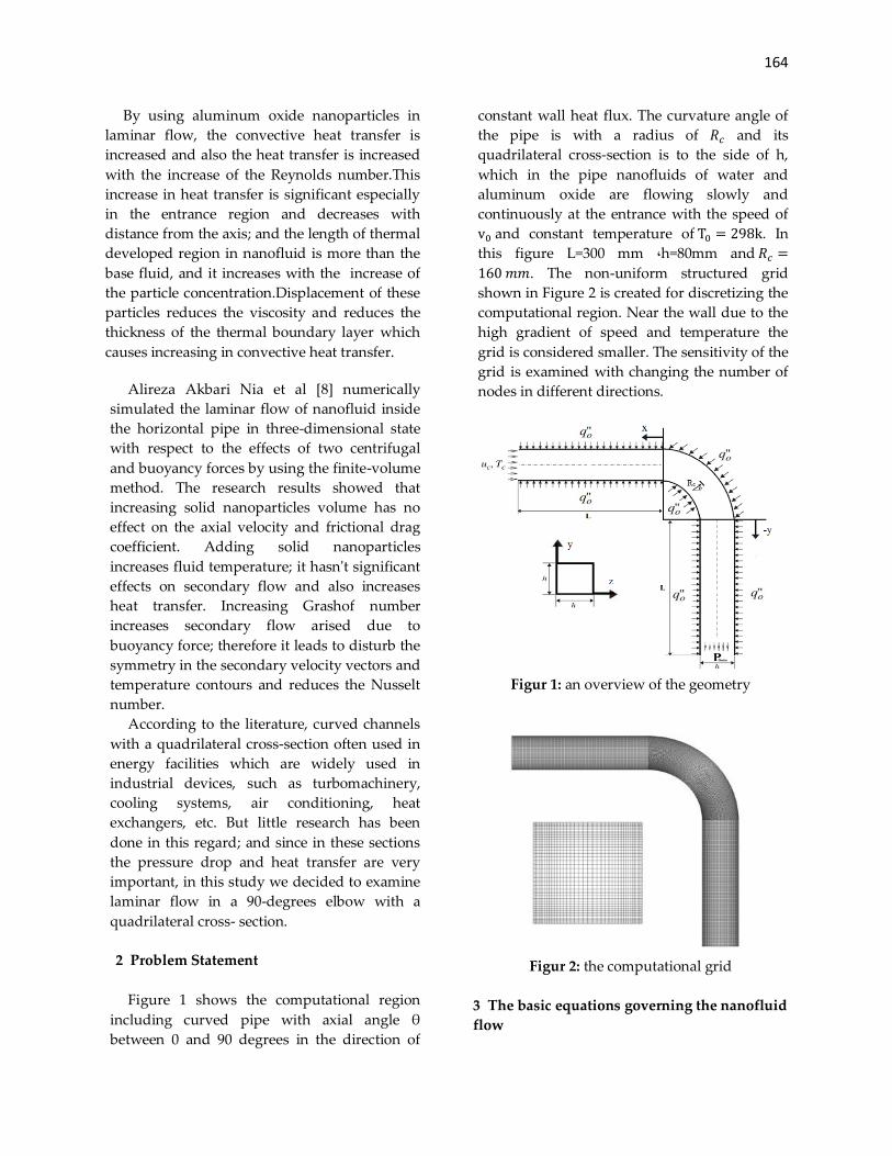
160 𝑚𝑚. The non-uniform structured grid
shown in Figure 2 is created for discretizing the
computational region. Near the wall due to the
high gradient of speed and temperature the
grid is considered smaller. The sensitivity of the
grid is examined with changing the number of
nodes in different directions.
Figur 1: an overview of the geometry
Figur 2: the computational grid
3 The basic equations governing the nanofluid
flow

165
In this study, it is assumed that the nanofluid
behaves as a homogeneous fluid and the flow of
boundary layer is slow and stable [9] and is
shown that nanofluids behave like the single-
phase fluids [10]. Energy production is
considered zero; and because nanoparticles' size
is extremely small, it seems reasonable that the
mixture can easily flow homogeneously inside
the pipe. So we can ignore sliding motion
between the phases and consider nanofluid as a
continuum environment with thermal
equilibrium between the base fluid and solid
particles. It is assumed that nanofluid is
incompressible with constant physical
properties, which all the properties are
calculated based on inlet temperature fluid as
reference. The work of expansion and viscous
losses in the energy equation are ignored.
The governing equations of laminar flow
inside the channel, assuming incompressible
Newtonian fluid and using the Boussinesq
Approximation are [11]:
(In the above equations subtitles are used as c=
cool surface, f= fluid, h= gram level, m= average,
nf= nanofluids, i =inlet conditions, s= solid, w=
wall).
Continuity equation:
∂u
∂x+
∂v
∂y+
∂w
∂z= 0 (1)
Where
x,y, are the Cartesian coordinates
u,v, and w are velocities in the x and y and (m/s)
z
Momentum equation:
(U∂U
∂X+ V
∂U
∂Y+ W
∂U
∂Z= −
∂P
∂X+
μnf
ρnf
υf
1
Re(
∂2U
∂X2+
∂2U
∂Y2+
∂2U
∂Z2)
(2)
(U∂V
∂X+ V
∂V
∂Y+ W
∂V
∂Z= −
∂P
∂Y+
μnf
ρnf
υf
1
Re(
∂2V
∂X2+
∂2V
∂Y2+
∂2V
∂Z2)
(3)
U∂W
∂X+ V
∂W
∂Y+ W
∂W
∂Z= −
∂P
∂Z+
μnf
ρnf
υf
1
Re(
∂2W
∂X2+
∂2W
∂Y2+
∂2W
∂Z2)
(4)
Where
X,Y,Z are dimensionless coordinates (X = x/L, Y
= y/L, Z = z/L)
U,V,W are dimensionless components of the
velocity (U = u/u_i, V = v/v_i, W = w/ (w_i))
Re is Reynolds number, P = fluid pressure, ρ =
the fluid density (kg m3)⁄ , υ =kinematic viscosity (m2 s⁄ )
Energy equation:
(U∂Θ
∂X+ V
∂Θ
∂Y+ W
∂Θ
∂Z) =
αnf
αf
1
Re.Pr(
∂2Θ
∂X2+
Θ
∂Y2+
∂2Θ
∂Z2) (5)
Where
𝜣 is dimensionless temperature (Θ =T − Tc Th − Tc⁄ )
α is thermal dispersion coefficient of fluid (m2 s⁄ )
Pr is Prandtl number (Pr = υf αf⁄ )
The dimensionless variables used in the
equations are defined as follows:
X =x
L‚ Y =
y
L‚ Z =
z
L‚ U =
u
ui‚ V =
v
vi
W =w
wi‚ Θ =
T − Tc
Th − Tc‚ P =
p̅
ρnf
ui2
Re =ρ
fuiL
μf
‚ Pr =υf
αf
4 Physical and thermal properties of
nanofluids:
The following formulas have been used to study
the physical and thermal properties of
nanofluid:
Nanofluid effective density [12]:
ρnf
= (1 − φ)ρf‚o
+ φρs‚o
(6)
Effective heat capacity of nanofluid:
(Cp)nf = [(1−φ)(ρCp)
f+φ(ρCp)
s
(1−φ)ρf+φρ
s
] (7)

166
The effective thermal conductivity and dynamic
viscosity of nanofluid provided by Ravikanth
and Debendra [13] are as the following
equations:
The effective thermal conductivity of nanofluids:
Knf =ks+2kf−2(kf−ks)
ks+2kf+(kf−ks)φkf +
5 × 10⁴βφρf(Cp)
f√
kT
ρs
dsf(T‚φ) (8)
The effective dynamic viscosity of nanofluids:
𝜇𝑛𝑓 = 5 × 10⁴βφρf√
𝑘𝑏T
ρs
dsf(T‚φ) (9)
f(T‚φ) = (2.8217 × 10⁻²φ + 3.917 ×
10−3) (T
T0) + (−3.0669 × 10⁻²φ − 3.91123 ×
10−3) (10)
β = 8.4407(100φ)−1.07304 (11)
1% < 𝜑 < 10%
298k < 𝑇 < 363𝑘
d is diameter of solid particles (20× 10−9) (m),
Cpis the specific heat (j kgk)⁄ , g= acceleration of
gravity (m/s^2), k= thermal conductivity
(w m2k)⁄ , Nu = Nusselt number (Nu =
ql k(Tw − Tc))⁄ , q" = heat flux (w m2)⁄ , Rc =
elbow's radius of curvature(m), L =
dimensionless diameter of pipe, T = temperature
(k), φ = Volume fraction of solid particles (%),
and θ is the angle of curvature (degree)
Table 1: Properties of Water and aluminum oxide particles [14]
Materials 𝛍(𝐩𝐚. 𝐬) 𝐂𝐩(
𝐉
𝐤𝐠𝐤) 𝛒(
𝐤𝐠
𝐦𝟑) 𝐤(
𝐖
𝐦𝐤)
Water
aluminum oxide
0.000993
------
4182
765
998.2
3970
0.613
40
5 Initial conditions and boundary conditions
To get the unique solution of a partial
differential equation, a set of additional
conditions are needed to determine optional
functions resulting from the integration of
partial differential equations. Mentioned
conditions are divided as boundary conditions
and initial conditions. In stability problems
equations merely requires boundary conditions.
In this problem we have used constant wall flux
boundary condition on the pipe walls because it
has many applications in energy facilities; And
also at the entrance we have used Velocity inlet
boundary condition due to incompressible flow
and at outlet we have used Pressure outlet
boundary condition to prevent backward flow.
A list of applied boundary conditions have been
identified in Table 2.
Table 2: boundary conditions
name type Boundary conditions
entrance
outlet
pipe wall
Velocity inlet
Pressure outlet
wall
w=v=0‚ u=1
P = 0
u=v=w=0‚ q = −k(∂T∂r⁄ )
6 Numerical Methods Equations of continuity, momentum and
energy with mentioned boundary conditions
167
were forced according to the finite difference
method based on the finite volume. These
equations were solved by Fluent Software; and
the heat transfer coefficient and the effective
dynamic viscosity were defined by open source
(UDF) written for software. Second order
upwind is used to discrete displacement and
governing equations. The momentum equations
are solved on the displaced grid. In displaced
grid, addition to easily calculate the rate of flow
on volume control, due to given speed on
surface, the amount of pressure is determined
on main point of grid. SIMPLE algorithm has
been used to solve algebraic equations; it is
described in detail in reference [15]. The
convergence criterion is considered as the
residual of velocities which is smaller than 10−6
at each stage. Three-dimensional geometry with
quadrilateral is modeled by Gambit software
and is used for simulation.
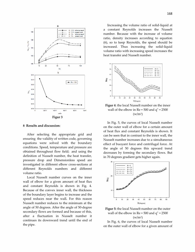
7 Verification of written code
To demonstrate the effectiveness of the
method and written program, a comparison has
been carried out between numerical results and
similar works by others. To evaluate computer
program performance developed in problems of
nanofluid convective heat transfer in curved
pipes, a comparison on nanofluid flow in an
elbow was performed according to [16]. In this
investigation, a 180-degree circular elbow is
exposed to the heat flux while a nanofluid is
flowing inside it. In this validation study,
changes of average Nusselt number ratios of the
nanofluid to the base fluid were investigated
with increasing nanoparticles concentration in
different Reynolds numbers. As indicated in Fig.
3a, there is a very small difference between the
results of reference [16] and the results of the
program. To evaluate the performance of the
program in flows inside the quadrilateral cross-
section pipe, its results are compared and
analyzed with done work in reference [17]. In
the above problem the air with temperature of
Tc = 298 enters to a square cross-section 90-
degree elbow and the wall is at the temperature
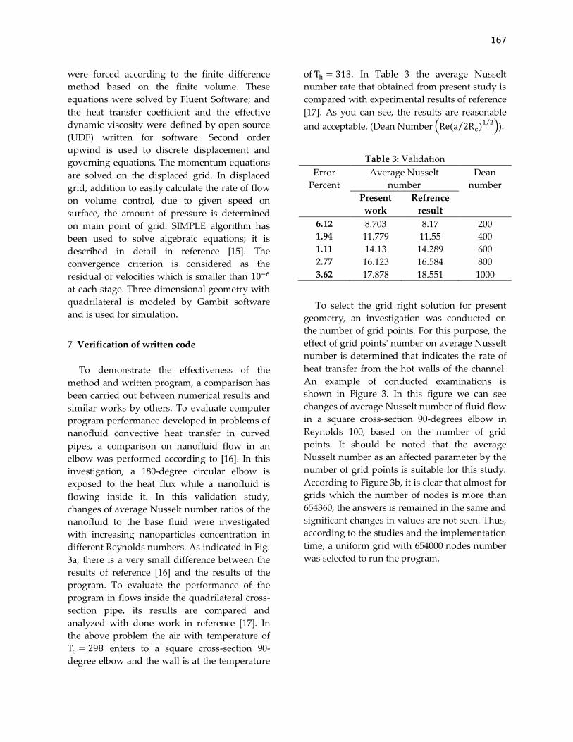
of Th = 313. In Table 3 the average Nusselt
number rate that obtained from present study is
compared with experimental results of reference
[17]. As you can see, the results are reasonable
and acceptable. (Dean Number (Re(a 2Rc)⁄ 1 2⁄)).
Table 3: Validation
Error
Percent
Average Nusselt
number
Dean
number
Present
work
Refrence
result
6.12
1.94
1.11
2.77
3.62
8.703
11.779
14.13
16.123
17.878
8.17
11.55
14.289
16.584
18.551
200
400
600
800
1000
To select the grid right solution for present
geometry, an investigation was conducted on
the number of grid points. For this purpose, the
effect of grid points' number on average Nusselt
number is determined that indicates the rate of
heat transfer from the hot walls of the channel.
An example of conducted examinations is
shown in Figure 3. In this figure we can see
changes of average Nusselt number of fluid flow
in a square cross-section 90-degrees elbow in
Reynolds 100, based on the number of grid
points. It should be noted that the average
Nusselt number as an affected parameter by the
number of grid points is suitable for this study.
According to Figure 3b, it is clear that almost for
grids which the number of nodes is more than
654360, the answers is remained in the same and
significant changes in values are not seen. Thus,
according to the studies and the implementation
time, a uniform grid with 654000 nodes number
was selected to run the program.
168
Figur 3
8 Results and discussion:
After selecting the appropriate grid and
ensuring the validity of written code, governing
equations were solved with the boundary
conditions. Speed, temperature and pressure are
obtained throughout flow field; and using the
definition of Nusselt number, the heat transfer,
pressure drop and Dimensionless speed are
investigated in different elbow cross-sections at
different Reynolds numbers and different
volume ratio.
Local Nusselt number curves on the inner
wall of elbow for a given amount of heat flux
and constant Reynolds is shown in Fig. 4.
Because of the convex inner wall, the thickness
of the boundary layer begins to increase and the
speed reduces near the wall. For this reason
Nusselt number reduces to the minimum at the
angle of 50 degrees. After the angle of 50-degree
secondary flows are formed and because of this,
after a fluctuation in Nusselt number it
continues its downward trend until the end of
the pipe.
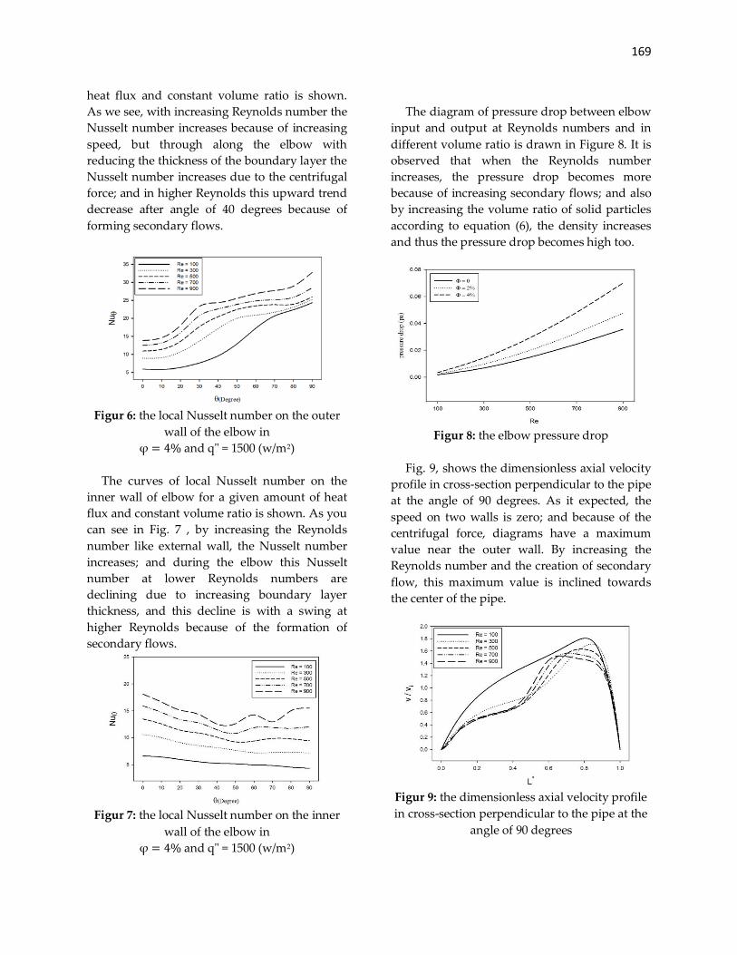
Increasing the volume ratio of solid-liquid at
a constant Reynolds increases the Nusselt
number. Because with the increase of volume
ratio, density increases according to equation
(6), so to keep Reynolds, the speed should be
increased. Thus increasing the solid-liquid
volume ratio with increasing speed increases the
heat transfer and Nusselt number.
Figur 4: the local Nusselt number on the inner
wall of the elbow in Re = 500 and q" = 2500
(w/m2)
In Fig. 5, the curves of local Nusselt number
on the outer wall of elbow for a certain amount
of heat flux and constant Reynolds is shown. It
can be seen that in contrast to the inner wall, the
Nusselt number increases due to a simultaneous
effect of buoyant force and centrifugal force. At
the angle of 50 degrees this upward trend
decreases by forming the secondary flows. But
in 70 degrees gradient gets higher again.
Figur 5: the local Nusselt number on the outer
wall of the elbow in Re = 500 and q" = 2500
(w/m2)
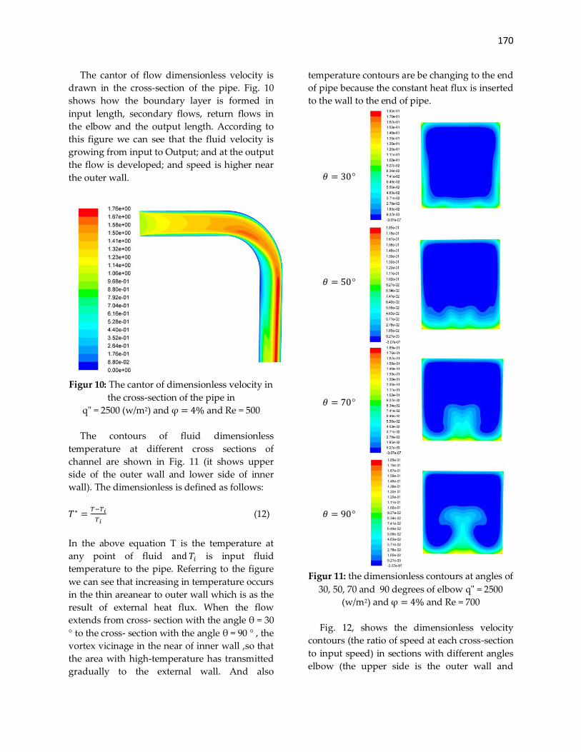
In Fig. 6, the curves of local Nusselt number
on the outer wall of elbow for a given amount of
169
heat flux and constant volume ratio is shown.
As we see, with increasing Reynolds number the
Nusselt number increases because of increasing
speed, but through along the elbow with
reducing the thickness of the boundary layer the
Nusselt number increases due to the centrifugal
force; and in higher Reynolds this upward trend
decrease after angle of 40 degrees because of
forming secondary flows.
Figur 6: the local Nusselt number on the outer
wall of the elbow in
φ = 4% and q" = 1500 (w/m2)
The curves of local Nusselt number on the
inner wall of elbow for a given amount of heat
flux and constant volume ratio is shown. As you
can see in Fig. 7 , by increasing the Reynolds
number like external wall, the Nusselt number
increases; and during the elbow this Nusselt
number at lower Reynolds numbers are
declining due to increasing boundary layer
thickness, and this decline is with a swing at
higher Reynolds because of the formation of
secondary flows.
Figur 7: the local Nusselt number on the inner
wall of the elbow in
φ = 4% and q" = 1500 (w/m2)
The diagram of pressure drop between elbow
input and output at Reynolds numbers and in
different volume ratio is drawn in Figure 8. It is
observed that when the Reynolds number
increases, the pressure drop becomes more
because of increasing secondary flows; and also
by increasing the volume ratio of solid particles
according to equation (6), the density increases
and thus the pressure drop becomes high too.
Figur 8: the elbow pressure drop
Fig. 9, shows the dimensionless axial velocity
profile in cross-section perpendicular to the pipe
at the angle of 90 degrees. As it expected, the
speed on two walls is zero; and because of the
centrifugal force, diagrams have a maximum
value near the outer wall. By increasing the
Reynolds number and the creation of secondary
flow, this maximum value is inclined towards
the center of the pipe.
Figur 9: the dimensionless axial velocity profile
in cross-section perpendicular to the pipe at the
angle of 90 degrees
170
The cantor of flow dimensionless velocity is
drawn in the cross-section of the pipe. Fig. 10
shows how the boundary layer is formed in
input length, secondary flows, return flows in
the elbow and the output length. According to
this figure we can see that the fluid velocity is
growing from input to Output; and at the output
the flow is developed; and speed is higher near
the outer wall.
Figur 10: The cantor of dimensionless velocity in
the cross-section of the pipe in
q" = 2500 (w/m2) and φ = 4% and Re = 500
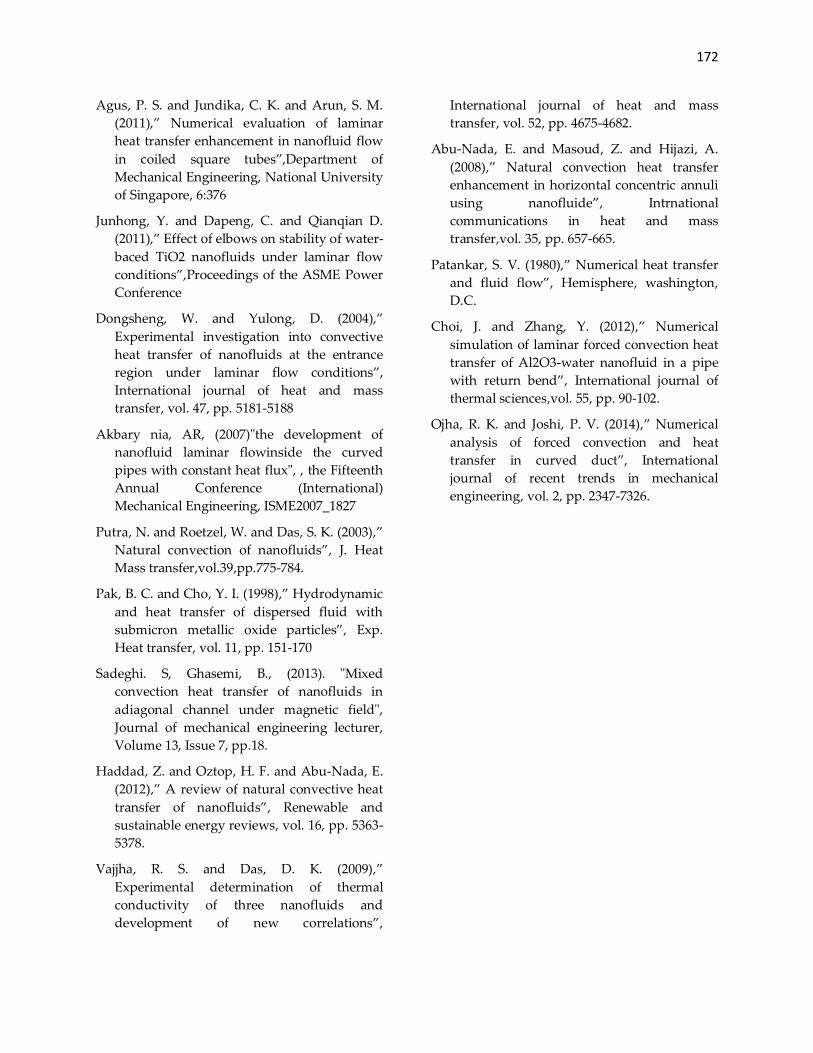
The contours of fluid dimensionless
temperature at different cross sections of
channel are shown in Fig. 11 (it shows upper
side of the outer wall and lower side of inner
wall). The dimensionless is defined as follows:
𝑇∗ =𝑇−𝑇𝑖
𝑇𝑖 (12)
In the above equation T is the temperature at
any point of fluid and 𝑇𝑖 is input fluid
temperature to the pipe. Referring to the figure
we can see that increasing in temperature occurs
in the thin areanear to outer wall which is as the
result of external heat flux. When the flow
extends from cross- section with the angle θ = 30
° to the cross- section with the angle θ = 90 ° , the
vortex vicinage in the near of inner wall ,so that
the area with high-temperature has transmitted
gradually to the external wall. And also
temperature contours are be changing to the end
of pipe because the constant heat flux is inserted
to the wall to the end of pipe.
𝜃 = 30°
𝜃 = 50°
𝜃 = 70°
𝜃 = 90°
Figur 11: the dimensionless contours at angles of
30, 50, 70 and 90 degrees of elbow q" = 2500
(w/m2) and φ = 4% and Re = 700
Fig. 12, shows the dimensionless velocity
contours (the ratio of speed at each cross-section
to input speed) in sections with different angles
elbow (the upper side is the outer wall and

171
lower side is the inner wall). Due to these
figures, the secondary flow after the angle of 50
degrees begins to form. Because of the low bend,
the flow is not developed in elbow length.
Also high speed area is inclined toward the
outer wall and the low speed area is transferred
to the central part of the cross section. These
changes are due to the centrifugal force.
𝜃 = 30°
𝜃 = 50°
𝜃 = 70°
𝜃 = 90°
Figur 12: the velocity dimensionless contours at
angles of 30, 50, 70 and 90 degrees of elbow
q" = 2500 (w/m2) and φ = 4% and Re = 700
9 Conclusion
laminar and steady flow of nanofluid inside a
pipe with a 90 degree elbow and the square
cross-section were studied with considering the
effects of two buoyancy and centrifugal forces in
the three-dimensional state with numerical
simulation by the Fluent software. It was found
that by increasing the buoyancy force, the
symmetry in the speed and temperature
contours is omitted, while it delays development
of axial velocity. In a given Reynolds number
and constant heat flux, increasing the volume
ratio of solid nanoparticles, increases the Nusselt
number and the fluid temperature but there is
no significant effect on the secondary flows. It
was also observed that the inner wall plays little
role in transferring heat as compared to the
outer wall, that is due to the creation of
secondary flows on the inner wall. It was
observed that increasing two parameters of
Rynoldz number and concentration of
nanoparticles increases the pressure drop due to
increasing secondary flows and density.
REFERENCES
Dean,W.R. (1927),”Not on the motion of fluid in
a curved pipe”,Phil.Mag.,l4,pp.208-.223.
Enayet, M. and Gibson M. M. and Yianneskis M.
(1982),” Measurements of turbulent
developing flow in a moderately curved
square duct”,Mechanical Engineering
Department, Imperial College of Science and
Technology
Mohammed‚ B. and Lionel‚ H. Gilmar‚ M. and
Laurent‚ T. (2008) ,” Numerical study of
Dean vortices in developing Newtonian and
viscoelastic flows through a curved duct of
square cross-section”,C. R. Mecanique‚ Vol.
337‚pp. 40-47.
Taofik‚ H. and Nassan, S. and Zeinali‚ H. and
Noie‚ S.H. (2010),” A comparison of
experimental heat transfer characteristics for
Al2O3/water and CuO/water nanofluids in
square cross-section duct”,International
communication in heat and mass transfer‚
vol. 37‚ pp. 924-928.
172
Agus‚ P. S. and Jundika‚ C. K. and Arun‚ S. M.
(2011),” Numerical evaluation of laminar
heat transfer enhancement in nanofluid flow
in coiled square tubes”,Department of
Mechanical Engineering, National University
of Singapore‚ 6:376
Junhong‚ Y. and Dapeng‚ C. and Qianqian D.
(2011),” Effect of elbows on stability of water-
baced TiO2 nanofluids under laminar flow
conditions”,Proceedings of the ASME Power
Conference
Dongsheng‚ W. and Yulong‚ D. (2004),”
Experimental investigation into convective
heat transfer of nanofluids at the entrance
region under laminar flow conditions”,
International journal of heat and mass
transfer‚ vol. 47‚ pp. 5181-5188
Akbary nia, AR, (2007)"the development of
nanofluid laminar flowinside the curved
pipes with constant heat flux", , the Fifteenth
Annual Conference (International)
Mechanical Engineering, ISME2007_1827
Putra‚ N. and Roetzel‚ W. and Das‚ S. K. (2003)‚”
Natural convection of nanofluids”‚ J. Heat
Mass transfer‚vol.39‚pp.775-784.
Pak‚ B. C. and Cho‚ Y. I. (1998)‚” Hydrodynamic
and heat transfer of dispersed fluid with
submicron metallic oxide particles”‚ Exp.
Heat transfer‚ vol. 11‚ pp. 151-170
Sadeghi. S, Ghasemi, B., (2013). "Mixed
convection heat transfer of nanofluids in
adiagonal channel under magnetic field",
Journal of mechanical engineering lecturer,
Volume 13, Issue 7, pp.18.
Haddad‚ Z. and Oztop‚ H. F. and Abu-Nada‚ E.
(2012)‚” A review of natural convective heat
transfer of nanofluids”‚ Renewable and
sustainable energy reviews‚ vol. 16‚ pp. 5363-
5378.
Vajjha‚ R. S. and Das‚ D. K. (2009)‚”
Experimental determination of thermal
conductivity of three nanofluids and
development of new correlations”‚
International journal of heat and mass
transfer‚ vol. 52‚ pp. 4675-4682.
Abu-Nada‚ E. and Masoud‚ Z. and Hijazi‚ A.
(2008)‚” Natural convection heat transfer
enhancement in horizontal concentric annuli
using nanofluide”‚ Intrnational
communications in heat and mass
transfer‚vol. 35‚ pp. 657-665.
Patankar‚ S. V. (1980)‚” Numerical heat transfer
and fluid flow”‚ Hemisphere‚ washington‚
D.C.
Choi‚ J. and Zhang‚ Y. (2012)‚” Numerical
simulation of laminar forced convection heat
transfer of Al2O3-water nanofluid in a pipe
with return bend”‚ International journal of
thermal sciences‚vol. 55‚ pp. 90-102.
Ojha‚ R. K. and Joshi‚ P. V. (2014)‚” Numerical
analysis of forced convection and heat
transfer in curved duct”‚ International
journal of recent trends in mechanical
engineering‚ vol. 2‚ pp. 2347-7326.