Embed Size (px)
Citation preview
University of Kentucky University of Kentucky
UKnowledge UKnowledge
Mechanical Engineering Faculty Publications Mechanical Engineering
6-2014
Numerical Investigation of Pyrolysis Gas Blowing Pattern and Numerical Investigation of Pyrolysis Gas Blowing Pattern and
Thermal Response using Orthotropic Charring Ablative Material Thermal Response using Orthotropic Charring Ablative Material
Haoyue Weng University of Kentucky, [email protected]
Alexandre Martin University of Kentucky, [email protected]
Follow this and additional works at: https://uknowledge.uky.edu/me_facpub
Part of the Aerodynamics and Fluid Mechanics Commons, and the Computer Sciences Commons
Right click to open a feedback form in a new tab to let us know how this document benefits you. Right click to open a feedback form in a new tab to let us know how this document benefits you.
Repository Citation Repository Citation Weng, Haoyue and Martin, Alexandre, "Numerical Investigation of Pyrolysis Gas Blowing Pattern and Thermal Response using Orthotropic Charring Ablative Material" (2014). Mechanical Engineering Faculty Publications. 2. https://uknowledge.uky.edu/me_facpub/2
This Conference Proceeding is brought to you for free and open access by the Mechanical Engineering at UKnowledge. It has been accepted for inclusion in Mechanical Engineering Faculty Publications by an authorized administrator of UKnowledge. For more information, please contact [email protected].
Numerical Investigation of Pyrolysis Gas Blowing Pattern and Thermal Response Numerical Investigation of Pyrolysis Gas Blowing Pattern and Thermal Response using Orthotropic Charring Ablative Material using Orthotropic Charring Ablative Material
Digital Object Identifier (DOI) http://dx.doi.org/10.2514/6.2014-2121
Notes/Citation Information Notes/Citation Information Published in the Proceedings of the 11th AIAA/ASME Joint Thermophysics and Heat Transfer Conference, Paper 2014-2121, p. 1-13.
Copyright © 2014 by Haoyue Weng and Alexandre Martin.
The copyright holders have granted the permission for posting the article here.
This conference proceeding is available at UKnowledge: https://uknowledge.uky.edu/me_facpub/2
Numerical Investigation of Pyrolysis Gas Blowing
Pattern and Thermal Response using Orthotropic
Charring Ablative Material
Haoyue Weng∗ and Alexandre Martin†
University of Kentucky, Lexington, KY, 40506
An orthotropic material model is implemented in a three-dimensional material responsecode, and numerically studied for charring ablative material. Model comparison is per-formed using an iso-Q sample geometry. The comparison is presented using pyrolysis gasstreamlines and time series of temperature at selected virtual thermocouples. Resultsshow that orthotropic permeability affects both pyrolysis gas flow and thermal response,but orthotropic thermal conductivity essentially changes the thermal performance of thematerial. The effect of orthotropic properties may have practical use such that the materialperformance can be manipulated by altering the angle of orthotropic orientation.
I. Introduction
Light-weight charring ablators have become a popular material to use in Thermal Protection Systems(TPS), for hypersonic atmospheric entry missions.1,2 Charring ablative materials are made of a fibrous
non-pyrolyzing matrix (carbon, ceramic, etc.) impregnated with pyrolyzing material (phenolic, silicon resin).One of the features of these materials is to absorb the aerodynamic heat through the endothermic reactionof pyrolysis and ablation.3 Pyrolysis is the process in which the pyrolyzing polymer gradually carbonizes athigh temperature, losing mass and generating pyrolysis gas. The other phenomenon, near surface ablation,occurs in a thin layer near the surface and refers to the mass removal of the char (composed of non-pyrolyzedand residual carbonized material) through oxidation, sublimation, and spallation.
Recently, Weng and Martin4 show that due to the high enthalpy carried by the pyrolysis gas, the gas flowbehavior within a charring ablator is crucial to the inner thermal response of the material. In addition, sincethe gas is eventually blown into the chemical reacting boundary layer,5 correct modeling of the pyrolysis gas isalso important to help determine the surface boundary conditions. The gas flow within the charring ablator isoften modeled as porous media flow, where steady-state Darcy’s law is usually assumed.6,7, 8, 9 For unsteadycharring ablation problems, however, Ref. 4 shows that steady-state of Darcy’s law is not necessarily validfor the whole geometry of small test articles used in arc-jet facilities. Hirata et. al.10 also proposed to use anunsteady version of Darcy’s law, and they also identified a side wall blowing effect on arc-jet test samples.However, their material property model is quite simple, especially for the permeability of the material,which was assumed to be constant. Marschall and Cox11 show a great difference between virgin and charproperties through experiments. In their work, the orthotropic behavior of charring ablative materials wasalso addressed. Specifically, ablative materials like PICA12 and SIRCA13 have different permeabilities andthermal conductivities between the in-plane (IP) direction and the through-the-thickness (TTT) direction.This behavior is due to the orientation of carbon (or ceramic) fibers on a micro scale.14 However, literaturesregarding the effect of orthotropic material properties are limited. This is perhaps due to the fact thatinvestigation of orthotropic model requires at least a two-dimensional (2D) code, while most of the MRsolvers are in one-dimensional (1D).15,16,17
Using the three-dimensional (3D) material response (MR) code developed in the present effort, the effectsof orthotropic material properties are numerically studied. In particular, the difference between isotropic
∗Graduate Research Assistant, Department of Mechanical Engineering, AIAA Student Member†Assistant Professor, Department of Mechanical Engineering, Associate Faculty – Center for Computational Science, AIAA
Senior Member
1
American Institute of Aeronautics and Astronautics
Dow
nloa
ded
by A
lexa
ndre
Mar
tin o
n D
ecem
ber
14, 2
014
| http
://ar
c.ai
aa.o
rg |
DO
I: 1
0.25
14/6
.201
4-21
21
11th AIAA/ASME Joint Thermophysics and Heat Transfer Conference
16-20 June 2014, Atlanta, GA
AIAA 2014-2121
Copyright © 2014 by Haoyue Weng and Alexandre Martin. Published by the American Institute of Aeronautics and Astronautics, Inc., with permission.
AIAA Aviation
and orthotropic model is investigated by looking at the thermal response and surface gas blowing pattern ofa charring ablative material. The outcome of this work demonstrates the implemented orthotropic materialmodel and its significance.
II. Numerical Framework
The 3D MR code developed in this work is Kentucky Aerodynamic and Thermal-response System(KATS).18,19 It is a paralleled code that uses ParMETIS20 for domain decomposition and MPI for mes-sage passing. KATS is based on finite volume method. The general conservation form of equations can bewritten as:
∂Q
∂t+∇ · (F− Fd) = S. (1)
Using backward Euler method and spatial integration, the following linear system is thus solved for eachcontrol volume, at each time step: [
V
∆t
∂Q
∂P− ∂RHS
∂P
]∆P = RHS, (2)
where P, Q, and S are vectors of primitive variables, conservative variables, and source terms, respectively.In this equation, RHS represents the right hand side of the linear system and is defined by:
RHS ≡ −∑faces
(F− Fd) · nA+ SV (3)
where F and Fd are respectively the matrices of convective and diffusive flux. The numerical schemeused to calculate the convective flux is AUSM+-up (Advection Upstream Splitting Method).21 The firstJacobian matrix ∂Q/∂P in Eq. (2) is calculated analytically and the second Jacobian ∂RHS/∂P is obtainednumerically via forward difference, where the perturbation to P is as small as the smallest positive floating-point number in double precision. The large sparse linear Eq. (2) is solved in the system at each time step,via PETSc library.22
III. Proposed models
The material response module in KATS solves for gaseous mass, solid mass, momentum and energyconservations. The governing equations, in the context of Eq. (1) and (2), can be represented by thefollowing vectors and matrices:
Q =
φρg
ρs1ρs2ρs3φρgu
φρgv
φρgw
φEg + Es
, P =
φρg
ρs1ρs2ρs3u
v
w
T
, S =
ωg
ωs1ωs2ωs3Dx
Dy
Dz
SD
, (4)
F =
φρgu φρgv φρgw
0 0 0
0 0 0
0 0 0
φρgu2 + p φρgvu φρgwu
φρguv φρgv2 + p φρgwv
φρguw φρgvw φρgw2 + p
φρguH φρgvH φρgwH
, Fd =
0
Fconduction
. (5)
2
American Institute of Aeronautics and Astronautics
Dow
nloa
ded
by A
lexa
ndre
Mar
tin o
n D
ecem
ber
14, 2
014
| http
://ar
c.ai
aa.o
rg |
DO
I: 1
0.25
14/6
.201
4-21
21
Pyrolysis gases model
In this work, the pyrolysis gases are assumed to be in chemical equilibrium and are treated as a single gasspecies. The gas properties (e.g. viscosity, heat capacity) are obtained via equilibrium calculations.
Solid decomposition model
For solid species, a phenomenological three-components model is used for the charring ablative material.15
The ablating surface recession, however, is not modeled in this work. The total solid density is computed by
ρs =
3∑i=1
Γiρsi , (6)
where Γi is the volume fraction of species i in the virgin composite. The intermediate properties are inter-polated from virgin and char state, including porosity φ, permeability K, thermal conductivity k, etc. Thedecomposition rate of each solid components is given by:
ωsi =∂ρsi∂t
= −Aiρvi(ρsi − ρciρvi
)ψi
exp
(−EiRT
), T > Treacti , (7)
where subscript v and c are respectively for virgin and char state of the solid material. The solid decompo-sition and pyrolysis gas generation balance themselves, thus ensuring total mass conservation:
ωg = −∂ρs∂t
= −3∑i=1
Γiωsi . (8)
Gas momentum model
In this work, the gas transport is solved in a distinct momentum equation, which is a time dependent versionof Darcy’s law.23 The diffusive effect of porous media is treated as a source term in each direction of themomentum equation, that is Dx, Dy, and Dz, as depicted in Eq. (4). These terms, in general, can becalculated by solving the following linear equation:Kxx Kxy Kxz
Kyx Kyy Kyz
Kzx Kzy Kzz
Dx
Dy
Dz
= −φµ(1 + Fo)
uvw
, (9)
where Fo is Forcheimer number and the term 1 + Fo accounts for high velocity effects on pore scale. Thethree-by-three matrix on the left hand side is a general anisotropic tensor of solid permeability. If thematerial is assumed to be orthotropic, such that the in-plane is the x-y plane and the through-the-thicknessdirection is the z-direction, Eq. (9) can be greatly simplified:KIP
KIP
KTTT
Dx
Dy
Dz
= −φµ(1 + Fo)
uvw
, (10)
⇒ Dx = − φµ
KIP(1 + Fo)u, Dy = − φµ
KIP(1 + Fo)v, Dz = − φµ
KTTT(1 + Fo)w. (11)
However, if the TTT direction is rotated by an angle θ (between TTT and z direction), Eq. (10) becomes:cos θ − sin θ 0
sin θ cos θ 0
0 0 1
KIP
KIP
KTTT
cos θ sin θ 0
− sin θ cos θ 0
0 0 1
Dx
Dy
Dz
= −φµ(1 + Fo)
uvw
, (12)
The diffusive effect of porous medium flow in the energy equation is modeled as a source term:
SD =
Dx
Dy
Dz
(u v w)
= Dxu+Dyv +Dzw (13)
3
American Institute of Aeronautics and Astronautics
Dow
nloa
ded
by A
lexa
ndre
Mar
tin o
n D
ecem
ber
14, 2
014
| http
://ar
c.ai
aa.o
rg |
DO
I: 1
0.25
14/6
.201
4-21
21
Mixture energy model
The mixture energy equation assumes the gas and solid are in thermal equilibrium. The conductive heatflux, as shown in Fd of Eq. (5), is also given in a generic anisotropic fashion as following:
Fconduction =
kxx kxy kxz
kyx kyy kyz
kzx kzy kzz
∂T/∂x∂T/∂y
∂T/∂z
. (14)
Similarly, if the material is orthotropic with z direction being TTT direction, Eq. (14) yields
Fcond,x = kIP∂T
∂x, Fcond,y = kIP
∂T
∂y, Fcond,z = kTTT
∂T
∂z. (15)
IV. Test Case Description
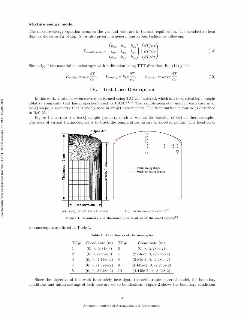
In this work, a total of seven cases is performed using TACOT material, which is a theoretical light-weightablative composite that has properties based as PICA.24,12 The sample geometry used in each case is aniso-Q shape, a geometry that is widely used in arc-jet experiments. The front surface curvature is describedin Ref. 25.
Figure 1 illustrates the iso-Q sample geometry mesh as well as the location of virtual thermocouples.The idea of virtual thermocouples is to track the temperature history of selected points. The location of
(a) Iso-Q (30×10+70×40 cells) (b) Thermocouples location26
Figure 1. Geometry and thermocouples location of the iso-Q sample25
thermocouples are listed in Table 1.
Table 1. Coordinates of thermocouples
TC# Coordinate (m) TC# Coordinate (m)
1 (0, 0, -3.81e-3) 6 (0, 0, -2.286e-2)
2 (0, 0, -7.62e-3) 7 (2.54e-2, 0, -2.286e-2)
3 (0, 0, -1.143e-2) 8 (3.81e-2, 0, -2.286e-2)
4 (0, 0, -1.524e-2) 9 (4.445e-2, 0, -2.286e-2)
5 (0, 0, -3.048e-2) 10 (4.445e-2, 0, -3.048-2)
Since the objective of this work is to solely investigate the orthotropic material model, the boundaryconditions and initial settings of each case are set to be identical. Figure 2 shows the boundary conditions
4
American Institute of Aeronautics and Astronautics
Dow
nloa
ded
by A
lexa
ndre
Mar
tin o
n D
ecem
ber
14, 2
014
| http
://ar
c.ai
aa.o
rg |
DO
I: 1
0.25
14/6
.201
4-21
21
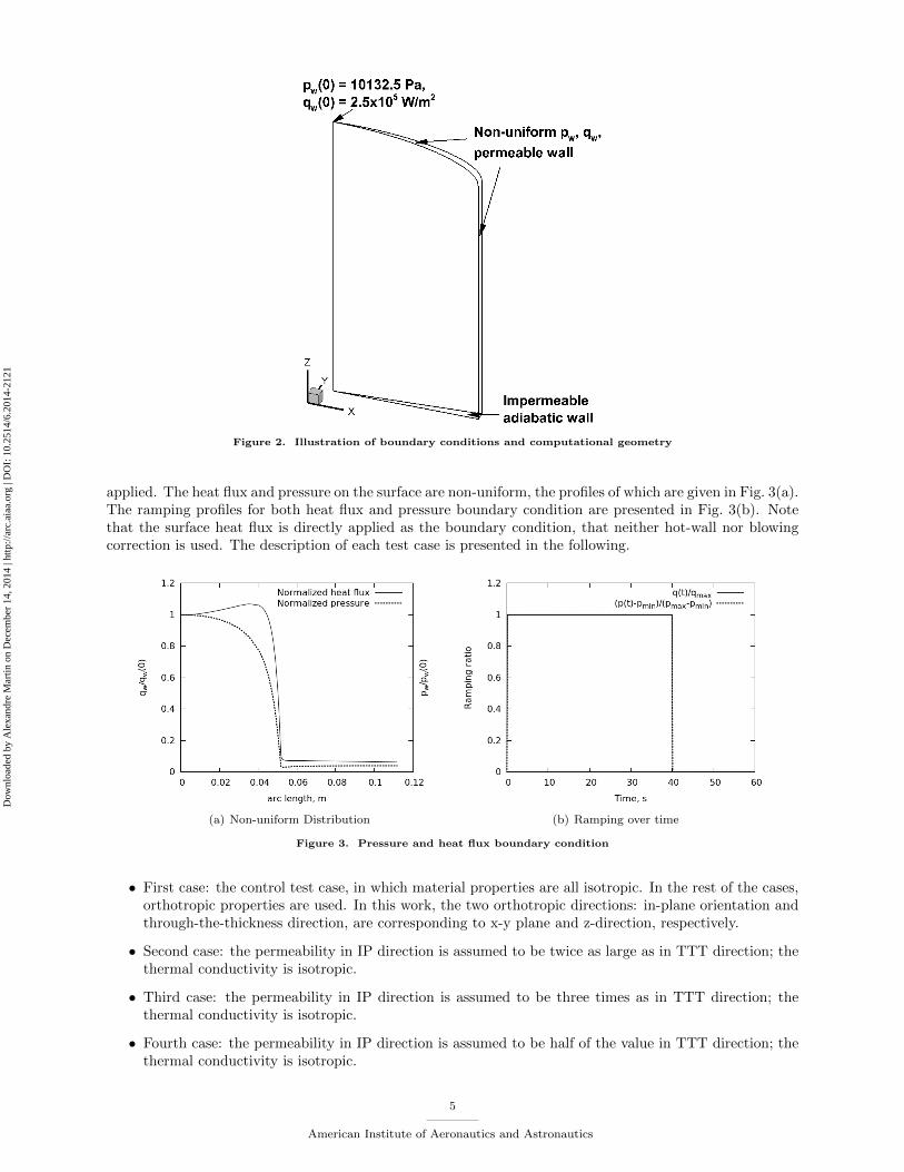
Figure 2. Illustration of boundary conditions and computational geometry
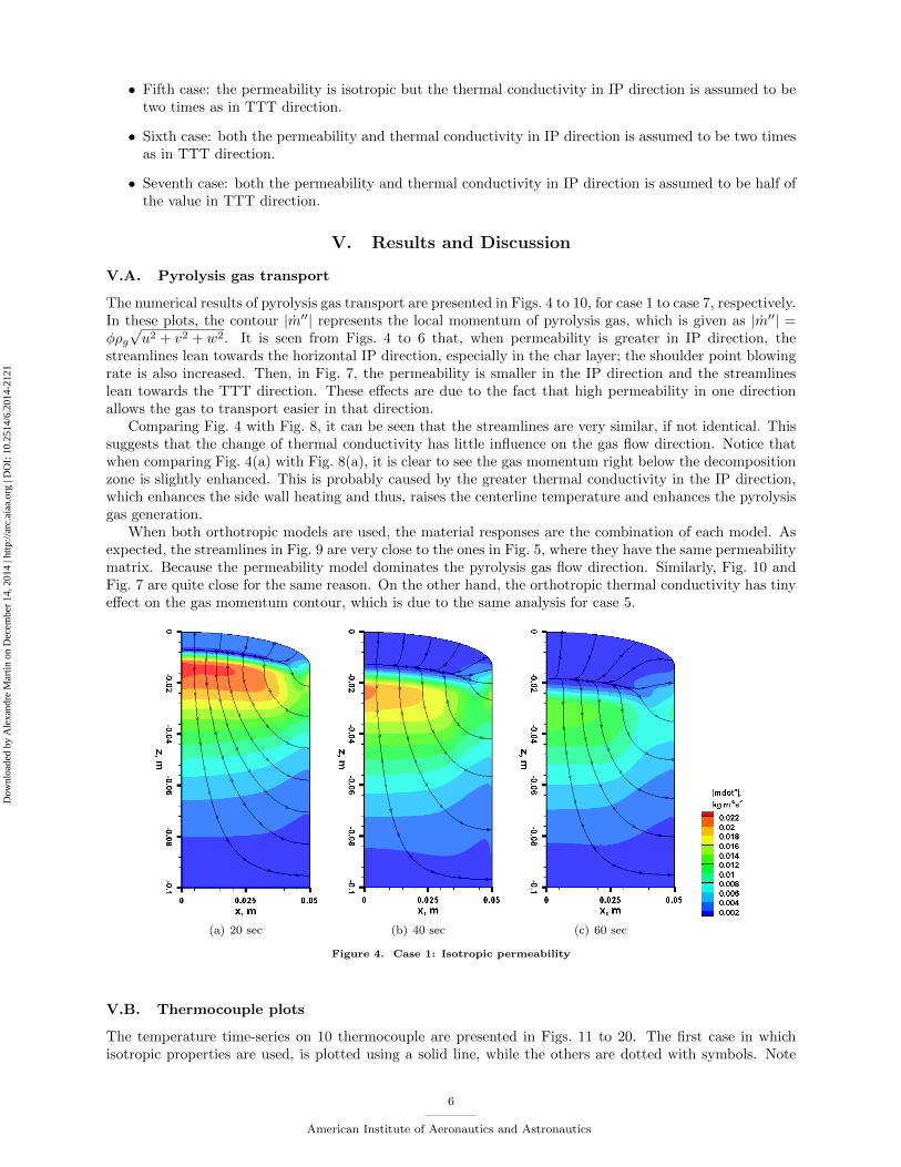
applied. The heat flux and pressure on the surface are non-uniform, the profiles of which are given in Fig. 3(a).The ramping profiles for both heat flux and pressure boundary condition are presented in Fig. 3(b). Notethat the surface heat flux is directly applied as the boundary condition, that neither hot-wall nor blowingcorrection is used. The description of each test case is presented in the following.
(a) Non-uniform Distribution (b) Ramping over time
Figure 3. Pressure and heat flux boundary condition
• First case: the control test case, in which material properties are all isotropic. In the rest of the cases,orthotropic properties are used. In this work, the two orthotropic directions: in-plane orientation andthrough-the-thickness direction, are corresponding to x-y plane and z-direction, respectively.
• Second case: the permeability in IP direction is assumed to be twice as large as in TTT direction; thethermal conductivity is isotropic.
• Third case: the permeability in IP direction is assumed to be three times as in TTT direction; thethermal conductivity is isotropic.
• Fourth case: the permeability in IP direction is assumed to be half of the value in TTT direction; thethermal conductivity is isotropic.
5
American Institute of Aeronautics and Astronautics
Dow
nloa
ded
by A
lexa
ndre
Mar
tin o
n D
ecem
ber
14, 2
014
| http
://ar
c.ai
aa.o
rg |
DO
I: 1
0.25
14/6
.201
4-21
21
• Fifth case: the permeability is isotropic but the thermal conductivity in IP direction is assumed to betwo times as in TTT direction.
• Sixth case: both the permeability and thermal conductivity in IP direction is assumed to be two timesas in TTT direction.
• Seventh case: both the permeability and thermal conductivity in IP direction is assumed to be half ofthe value in TTT direction.
V. Results and Discussion
V.A. Pyrolysis gas transport
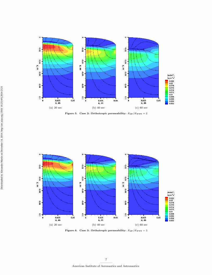
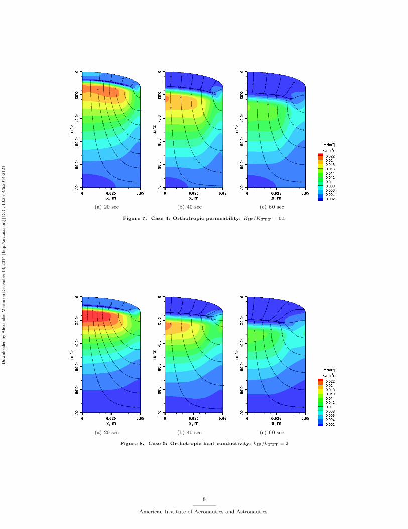
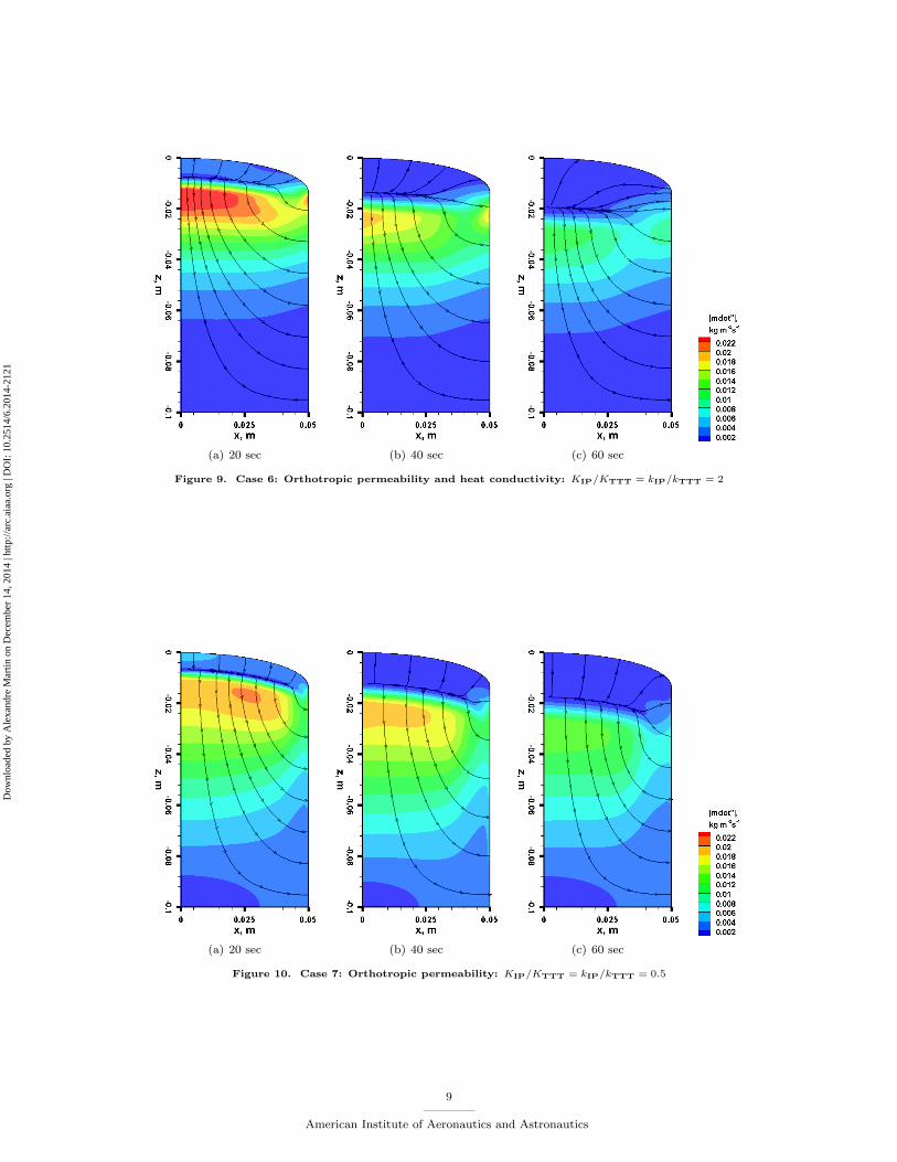
The numerical results of pyrolysis gas transport are presented in Figs. 4 to 10, for case 1 to case 7, respectively.In these plots, the contour |m′′| represents the local momentum of pyrolysis gas, which is given as |m′′| =φρg√u2 + v2 + w2. It is seen from Figs. 4 to 6 that, when permeability is greater in IP direction, the
streamlines lean towards the horizontal IP direction, especially in the char layer; the shoulder point blowingrate is also increased. Then, in Fig. 7, the permeability is smaller in the IP direction and the streamlineslean towards the TTT direction. These effects are due to the fact that high permeability in one directionallows the gas to transport easier in that direction.
Comparing Fig. 4 with Fig. 8, it can be seen that the streamlines are very similar, if not identical. Thissuggests that the change of thermal conductivity has little influence on the gas flow direction. Notice thatwhen comparing Fig. 4(a) with Fig. 8(a), it is clear to see the gas momentum right below the decompositionzone is slightly enhanced. This is probably caused by the greater thermal conductivity in the IP direction,which enhances the side wall heating and thus, raises the centerline temperature and enhances the pyrolysisgas generation.
When both orthotropic models are used, the material responses are the combination of each model. Asexpected, the streamlines in Fig. 9 are very close to the ones in Fig. 5, where they have the same permeabilitymatrix. Because the permeability model dominates the pyrolysis gas flow direction. Similarly, Fig. 10 andFig. 7 are quite close for the same reason. On the other hand, the orthotropic thermal conductivity has tinyeffect on the gas momentum contour, which is due to the same analysis for case 5.
(a) 20 sec (b) 40 sec (c) 60 sec
Figure 4. Case 1: Isotropic permeability
V.B. Thermocouple plots
The temperature time-series on 10 thermocouple are presented in Figs. 11 to 20. The first case in whichisotropic properties are used, is plotted using a solid line, while the others are dotted with symbols. Note
6
American Institute of Aeronautics and Astronautics
Dow
nloa
ded
by A
lexa
ndre
Mar
tin o
n D
ecem
ber
14, 2
014
| http
://ar
c.ai
aa.o
rg |
DO
I: 1
0.25
14/6
.201
4-21
21
(a) 20 sec (b) 40 sec (c) 60 sec
Figure 5. Case 2: Orthotropic permeability: KIP/KTTT = 2
(a) 20 sec (b) 40 sec (c) 60 sec
Figure 6. Case 3: Orthotropic permeability: KIP/KTTT = 3
7
American Institute of Aeronautics and Astronautics
Dow
nloa
ded
by A
lexa
ndre
Mar
tin o
n D
ecem
ber
14, 2
014
| http
://ar
c.ai
aa.o
rg |
DO
I: 1
0.25
14/6
.201
4-21
21
(a) 20 sec (b) 40 sec (c) 60 sec
Figure 7. Case 4: Orthotropic permeability: KIP/KTTT = 0.5
(a) 20 sec (b) 40 sec (c) 60 sec
Figure 8. Case 5: Orthotropic heat conductivity: kIP/kTTT = 2
8
American Institute of Aeronautics and Astronautics
Dow
nloa
ded
by A
lexa
ndre
Mar
tin o
n D
ecem
ber
14, 2
014
| http
://ar
c.ai
aa.o
rg |
DO
I: 1
0.25
14/6
.201
4-21
21
(a) 20 sec (b) 40 sec (c) 60 sec
Figure 9. Case 6: Orthotropic permeability and heat conductivity: KIP/KTTT = kIP/kTTT = 2
(a) 20 sec (b) 40 sec (c) 60 sec
Figure 10. Case 7: Orthotropic permeability: KIP/KTTT = kIP/kTTT = 0.5
9
American Institute of Aeronautics and Astronautics
Dow
nloa
ded
by A
lexa
ndre
Mar
tin o
n D
ecem
ber
14, 2
014
| http
://ar
c.ai
aa.o
rg |
DO
I: 1
0.25
14/6
.201
4-21
21
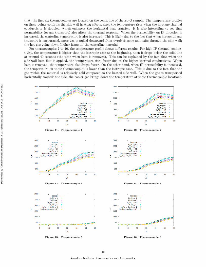
that, the first six thermocouples are located on the centerline of the iso-Q sample. The temperature profileson these points confirms the side wall heating effects, since the temperature rises when the in-plane thermalconductivity is doubled, which enhances the horizontal heat transfer. It is also interesting to see thatpermeability (or gas transport) also alters the thermal response. When the permeability on IP direction isincreased, the centerline temperature is also increased. This is likely due to the fact that when horizontal gastransport is encouraged, more gas is pulled downward from pyrolysis zone and exits through the side-wall;the hot gas going down further heats up the centerline material.
For thermocouples 7 to 10, the temperature profile shows different results. For high IP thermal conduc-tivity, the temperature is higher than the isotropic case at the beginning, then it drops below the solid lineat around 40 seconds (the time when heat is removed). This can be explained by the fact that when theside-wall heat flux is applied, the temperature rises faster due to the higher thermal conductivity. Whenheat is removed, the temperature also drops faster. On the other hand, when IP permeability is increased,the temperature on these thermocouples is lower than the isotropic case. This is due to the fact that thegas within the material is relatively cold compared to the heated side wall. When the gas is transportedhorizontally towards the side, the cooler gas brings down the temperature at these thermocouple locations.
Figure 11. Thermocouple 1 Figure 12. Thermocouple 2
Figure 13. Thermocouple 3 Figure 14. Thermocouple 4
Figure 15. Thermocouple 5 Figure 16. Thermocouple 6
10
American Institute of Aeronautics and Astronautics
Dow
nloa
ded
by A
lexa
ndre
Mar
tin o
n D
ecem
ber
14, 2
014
| http
://ar
c.ai
aa.o
rg |
DO
I: 1
0.25
14/6
.201
4-21
21
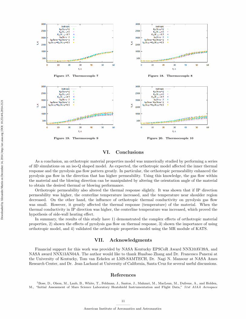
Figure 17. Thermocouple 7 Figure 18. Thermocouple 8
Figure 19. Thermocouple 9 Figure 20. Thermocouple 10
VI. Conclusions
As a conclusion, an orthotropic material properties model was numerically studied by performing a seriesof 3D simulations on an iso-Q shaped model. As expected, the orthotropic model affected the inner thermalresponse and the pyrolysis gas flow pattern greatly. In particular, the orthotropic permeability enhanced thepyrolysis gas flow in the direction that has higher permeability. Using this knowledge, the gas flow withinthe material and the blowing direction can be manipulated by altering the orientation angle of the materialto obtain the desired thermal or blowing performance.
Orthotropic permeability also altered the thermal response slightly. It was shown that if IP directionpermeability was higher, the centerline temperature increased, and the temperature near shoulder regiondecreased. On the other hand, the influence of orthotropic thermal conductivity on pyrolysis gas flowwas small. However, it greatly affected the thermal response (temperature) of the material. When thethermal conductivity in IP direction was higher, the centerline temperature was increased, which proved thehypothesis of side-wall heating effect.
In summary, the results of this study have 1) demonstrated the complex effects of orthotropic materialproperties, 2) shown the effects of pyrolysis gas flow on thermal response, 3) shown the importance of usingorthotropic model, and 4) validated the orthotropic properties model using the MR module of KATS.
VII. Acknowledgments
Financial support for this work was provided by NASA Kentucky EPSCoR Award NNX10AV39A, andNASA award NNX13AN04A. The author would like to thank Huaibao Zhang and Dr. Francesco Panerai atthe University of Kentucky, Tom van Eekelen at LMS-SAMTECH, Dr. Nagi N. Mansour at NASA AmesResearch Center, and Dr. Jean Lachaud at University of California, Santa Cruz for several useful discussions.
References
1Bose, D., Olson, M., Laub, B., White, T., Feldman, J., Santos, J., Mahzari, M., MacLean, M., Dufrene, A., and Holden,M., “Initial Assessment of Mars Science Laboratory Heatshield Instrumentation and Flight Data,” 51st AIAA Aerospace
11
American Institute of Aeronautics and Astronautics
Dow
nloa
ded
by A
lexa
ndre
Mar
tin o
n D
ecem
ber
14, 2
014
| http
://ar
c.ai
aa.o
rg |
DO
I: 1
0.25
14/6
.201
4-21
21
Sciences Meeting, AIAA Paper 2013-908, Grapevine, TX, January 7-10 2013.doi:doi:10.2514/6.2013-908
2Vellinga, J., Craig, C. L., Gellis, R. T., Rasback, C. E., Rogers, J. J., Thorton, M. G., Willcockson, W. H., Brownlee,D. E., and Atkins, K. L., “Enviromental Design Considerations for Stardust,” Technical Paper 972278, Society of AutomotiveEngineers, July 1997.
3Mansour, N. N., Panerai, F., Martin, A., Parkinson, D. Y., MacDowell, A. A., Haboub, A., Sandstrom, T. A., Fast, T.,Vignoles, G. L., and Lachaud, J., “A New Approach To Light-Weight Ablators Analysis: From Micro-Tomography Measure-ments to Statistical Analysis and Modeling,” 44th AIAA Thermophysics Conference, AIAA, San Diego, CA, June 24-27 2013.doi:10.2514/6.2013-2768
4Weng, H. and Martin, A., “Multi-dimensional Modeling of Pyrolysis Gas Transport Inside Charring Ablative Materials,”Journal of Thermophysics and Heat Transfer , Accepted on March 12 2014.
5Alkandry, H., Boyd, I. D., and Martin, A., “Coupled Flow Field Simulations of Charring Ablators with NonequilibriumSurface Chemistry,” 44th AIAA Thermophysics Conference, AIAA, San Diego, California, June 24-27 2013.doi:10.2514/6.2013-2634
6van Eekelen, T., Bouilly, J.-M., Hudrisier, S., Dupillier, J.-M., and Aspa, Y., “Design and numerical modelling of charringmaterial ablators for re-entry applications,” 6th European Workshop on Thermal Protection Systems and Hot Structures,European Space Agency - WPP-319, University Stuttgart, Germany, November 21-25 2009.
7Amar, A. J., Calvert, N. D., and Kirk, B. S., “Development and Verification of the Charring Ablating Thermal ProtectionImplicit System Solver,” 49th AIAA Aerospace Sciences Meeting and Exhibit , AIAA paper 2011-144, Orlando, FL, January4-7 2011.doi:10.2514/6.2011-144
8Ewing, M. E. and Richardson, D. E., “Phenomena and material property requirements for a combined structural andthermal ablation model,” 4th AFOSR/SNL/NASA Ablation Workshop, Albuquerque, NM, March 2011.
9Lachaud, J. and Mansour, N. N., “A pyrolysis and ablation toolbox based on OpenFOAM - with application to materialresponse under high-enthalpy environments,” 5th OpenFOAM Workshop, Chalmers University, Gothenburg, Sweden, June2010.
10Hirata, N., Nozawa, S., Takahashi, Y., Kihara, H., and ichi Abe, K., “Numerical study of pyrolysis gas flow and heattransfer inside an ablator,” Computational Thermal Sciences, Vol. 4, No. 3, 2012, pp. 225–242.doi:10.1615/ComputThermalScien.2012004762
11Marschall, J. and Cox, M. E., “Gas Permeability of Lightweight Ceramic Ablators,” Journal of Thermophysics and HeatTransfer , Vol. 13, No. 3, 1999, pp. 383–386.doi:10.2514/2.6451
12Tran, H. K., Johnson, C. E., Rasky, D. J., Hui, F. C. L., Hsu, M.-T., Chen, T., Chen, Y. K., Paragas, D., and Kobayashi,L., “Phenolic impregnated carbon ablators (PICA) as thermal protection systems for discovery missions,” Technical Report110440, NASA Technical Memorandum, 1997.
13Tran, H. K., Johnson, C., Rasky, D., Hui, F., and Hsu, M.-T., “Silicone Impregnated Reusable Ceramic Ablators forMars Follow-On Missions,” AIAA paper 96-1819, June 1996.
14Marschall, J. and Milos, F. S., “Gas permeability of rigid fibrous refractory insulations,” Journal of Thermophysics andHeat Transfer , Vol. 12, No. 4, 1998, pp. 528–535.doi:10.2514/2.6451
15Moyer, C. B. and Rindal, R. A., “AN ANALYSIS OF THE COUPLED CHEMICALLY REACTING BOUNDARYLAYER AND CHARRING ABLATOR PART I,” Contractor report, NASA, 1968.
16Chen, Y.-K. and Milos, F. S., “Ablation and Thermal Response Program for Spacecraft Heatshield Analysis,” Journalof Spacecraft and Rockets, Vol. 36, No. 3, May-June 1999, pp. 475–483.doi:10.2514/2.3469
17Martin, A. and Boyd, I. D., “Non-Darcian Behavior of Pyrolysis Gas in a Thermal Protection System,” Journal ofThermophysics and Heat Transfer , Vol. 24, No. 1, January-March 2010, pp. 60–68.doi:10.2514/1.44103
18Weng, H., Zhang, H., Khan, O. U., and Martin, A., “Multi-dimensional modeling of charring ablators,” 43rd AIAAThermophysics Conference, AIAA Paper 2012-2748, New Orlean, LA, June 25-28 2012.doi:10.2514/6.2012-2748
19Zhang, H., Martin, A., and McDonough, J. M., “Parallel Efficiency of the FreeCFD Code for Hypersonic Flows withChemistry,” 24th International Conference on Parallel Computational Fluid Dynamics, Atlanta, GA, May 21-25 2012.
20Schloegel, K., Karypis, G., and Kumar., V., “Parallel Multilevel Algorithms for Multi-Constraint Graph Partitioning,”Euro-Par , 2000, pp. 296–310.
21Liou, M.-S., “A sequel to AUSM, Part II: AUSM+-up for all speeds,” Journal of Computational Physics, Vol. 214, No. 1,2006, pp. 137 – 170.doi:10.1016/j.jcp.2005.09.020
22Balay, S., Brown, J., Buschelman, K., Gropp, W.-D., Kaushik, D., Knepley, M.-G., McInnes, L.-C., Smith, B.-F., andZhang, H., “PETSc Web page http://www.mcs.anl.gov/petsc,” 2013.
23Darcy, H., “Les Fontaines Publiques de la Ville de Dijon,” Dalmont, Paris, France, 1856.24Lachaud, J., Martin, A., Cozmuta, I., and Laub, B., “Ablation test-case series #1,” 4th AFOSR/SNL/NASA Ablation
Workshop, Albuquerque, NM, March 1-3 2010.25van Eekelen, T., Martin, A., Lachaud, J., and Bianchi, D., “Ablation test-case series #3: Numerical simulation of
ablative-material response: code and model comparisons,” 6th Ablation Workshop, Urbana Champaign, IL, February 2014.
12
American Institute of Aeronautics and Astronautics
Dow
nloa
ded
by A
lexa
ndre
Mar
tin o
n D
ecem
ber
14, 2
014
| http
://ar
c.ai
aa.o
rg |
DO
I: 1
0.25
14/6
.201
4-21
21
26Milos, F. S. and Chen, Y.-K., “Two-Dimensional Ablation, Thermal Response, and Sizing Program for PyrolyzingAblators,” Journal of Spacecraft and Rockets, Vol. 46, No. 6, November-December 2009, pp. 1089–1099.doi:10.2514/1.36575
13
American Institute of Aeronautics and Astronautics
Dow
nloa
ded
by A
lexa
ndre
Mar
tin o
n D
ecem
ber
14, 2
014
| http
://ar
c.ai
aa.o
rg |
DO
I: 1
0.25
14/6
.201
4-21
21