Embed Size (px)
Citation preview

Mechanics & Industry 14, 317–324 (2013)c© AFM, EDP Sciences 2013DOI: 10.1051/meca/2013071www.mechanics-industry.org
Mechanics&Industry
Numerical investigation of thermal characteristicsof confined rotating multi-jet
Mohamed Roudane1,a, Larbi Loukarfi2, Ali Khelil2 and Mohamed Hemis3
1 Faculte de Genie Mecanique, USTO Oran, Algerie2 Universite Hassiba Benbouali, Chlef, Algerie3 Universite de Khemis Meliana, Algerie
Received 16 May 2013, Accepted 11 August 2013
Abstract – For using the swirling jet for air conditioning and heating in the premises, knowledge of thethermal characteristics is more than necessary. It is for this objective that the experimental and numericalstudy was realized. To conduct this study, we designed and built an experimental facility to ensure properconditions of confinement in which we placed five air blowing devices with adjustable vanes, providingmultiple swirling turbulent jet with a swirl number S = 0.4. The jets were issued in the same direction andthe same spacing defined between them. This study concerned the numerical simulation of the thermalmixing of confined swirling multi-jets, and examined the influence of important parameters of a swirldiffuser system on the performance characteristics. The experimental measurements are also realized for aconfined domain, aiming to determine the axial and radial temperature field. The CFD investigations arecarried out by an unstructured mesh to discretize the computational domain. In this work, the simulationshave been performed using the finite volume method and FLUENT solver, in which the standard k-ε, K-εrealizable, k-ε RNG and the RSM turbulence model were used for turbulence computations. The validationshows that the K-ε RNG model can be used to simulate this case successfully.
Key words: Multiple rotating jet / thermal characteristics / turbulence models / ventilation improvement
1 Introduction
The confined multiple rotating jets were used in sev-eral industrial applications. They are very importantpractical interest in the technology of air conditioning sys-tems, cooling and combustion. The rotating jet enhancesmixing processes and mass and heat transfer and causesa change in the mean flow such as the properties of theturbulence. Under the effect of turbulence, the fluid par-ticles have a tendency to move away from the axis underthe effect of centrifugal force.
Depending on the literature, there is no more researchbeing done, on the multiple rotating jets applied to im-prove comfort conditions. Most of the literatures whichdeal with multiple rotating jets in various geometric or dy-namic and thermal conditions are aimed to the improve-ment of combustion. Swirl flows have been widely usedin combustion systems as they enhance mixing betweenfuel and oxidant [1, 2]. Practically, they are found in air-craft combustors and in a burner where swirl contributesto improve mixing and stabilizes the flame. They are also
a Corresponding author: Roudane [email protected]
widely used in industrial burners or gas turbine combus-tors to give stable, high intensity, short flames with wideradial development resulting from good fluid mixing [3].Consequently, it is worth noting that, there are still manypoints to be clarified concerning the understanding of theeffect of rotating jet on the heat transfer and behaviorof the armature flow. It has been noted that from a cer-tain intensity of swirl, a recirculation zone appeared inthe main flow. The form and position of the recircula-tion zone will vary with the intensity of the swirl [2–5].This area is essential to stabilize the combustion becauseit contains fresh gas preheated and allows the attach-ment of the flame. The velocity profiles of a low swirlingflow (S < 0.5) takes a Gaussian form and from approx-imately S = 0.6, the longitudinal pressure gradients arenot sufficient to compensate for the kinetic energy of fluidparticles so appears a toroidal recirculation zone in theflow [2]. Thielen et al. [6] presented the numerical simu-lation of flow and heat transfer in multiple jets impingingnormally on a flat heated surface, obtained with a newsecond-moment turbulence closure combined with an el-liptic blending model of non-viscous wall blocking effect.According to authors, this model offers the mean velocity
Article published by EDP Sciences

318 M. Roudane et al.: Mechanics & Industry 14, 317–324 (2013)
Nomenclature
D Diffuser outside diameter, md Diffuser inside diameter, mGθ Axial flux tangential momentum, kg.m2.s−2
Gx Axial momentum flux, kg.m2.s−2
K Turbulent kinetic energy, m2.s−2
P Pressure in a section of the jet, PaQm Gas mass flow rate, kg.s−1
r Radial coordinate of air flow, mR Characteristic radius, mRe0 Reynolds number at air blowingS Swirl numberT Temperature of jet, ◦CT0 Air blowing maximum
temperature near the inlet orifice, ◦CTa Ambient temperature, ◦CTr Dimensionless temperatureU Mean axial velocity, m.s−1
Uo Air blowing maximum velocitynear the inlet orifice, m.s−1
V Mean radial velocity, m.s−1
W Mean tangential velocity, m.s−1
x Axial coordinate of the air flow, mGreek symbols
α Vanes angle inclinationε Turbulent dissipation rate, m2.s−3
μt Turbulent viscosity, kg.m−1.s−1
ρ Fluid density, kg.m−3
and turbulent stress fields in very good agreement withPIV measurements. They explored a number of simplerclosures for the passive thermal field, conducted in par-allel and they confirmed that the major prerequisite forthe correct prediction of the temperature field and heattransfer is to calculate accurately the velocity and stressfields.
Rady [7] presented a study to determine the charac-teristics of flow and heat transfer of an impinging multijet used for cooling of a flat plate equipped with exhaustports in confinement. The experiments were realized tak-ing into consideration the different values of Reynolds,the distance between the plate and the jet and the posi-tioning of the exhaust ports. Points drawn from this workare listed below:
– Increasing the rate of heat transfer is relative to thedecrease of the distance between the plate and thejet. Acceleration of the flow, at the approach of thescattering surface of the jets, excites relatively heattransfer in the downstream.
– Positioning of the jets of exhaust ports contributesto the structural change of the flow rate and the re-duction of the interaction between the inflow and theoutflow.
Bouziane et al. [8] studied numerically a reactive flowgenerated downstream swirler, three turbulence models:RNG K-ε, standard K-ε and realizable K-ε. They de-duced from this study that the superposition of the graphsshowing the profiles of the radial component of the axial
velocity and the temperature can be an acceptable valuefor the study of the recirculation zone in a combustionchamber. According to Braikia et al. [9] the optimizationof parameters for instance the geometry of the diffuser,the slope of the initial speed (number of swirl), the gapbetween jets, the number of jets blown, the inclination ofthe jets relative to the lateral central axis of the jet, the jetflow relative peripheral and central jet, can significantlyimprove the quality of air in mixtures of local coolingor gas containments. According to Aroussi et al. [10] themodels realizable K-ε, the standard K-ε, RSM and RNGK ε-suited for the simulation of multiple turbulent jetsin burners. From the standpoint economy in computationtime, the model realizable K-ε is more suitable than theother models. Elbanna et al. [11] visualized the interactionof two-dimensional air jets, distributed, parallel, impact-ing on a flat surface for use in aircraft vertical takeoffand landing. They visualize the effect of the drive aroundthe blasting orifices. Confluent jets ventilation at x/D isgreater than unventilated. The rectangular holes reducesuction vortex better than round jets. They establish thedistribution of the pressure fields through the confluenceof the jets. The influence of turbulence is important nearthe side of the jet “weakest”. Kazuya et al. [12] carriedout a 3D numerical simulation to study the effects of swirland buoyancy driven flows on the mixing performance of abaffle-plate-type miniature confined multi jet. Accordingto authors the rotating flow was created by inclining thejet nozzles surrounding the central jet in the circumferen-tial direction. The results achieved were compared withthose of the non-swirl case. They found that the rotat-ing flow interrupted the radial secondary flow producedin the region adjacent to the baffle plate.
According to Kazuya et al., this interruption de-creased the size of the reverse flow region, resulting ina deterioration of the mixing performance. They notedthat this performance was more perceptible in the caseof a large swirl number. Hirai et al. [13] studied the nu-merical prediction of flow characteristics and retardationmixing in a turbulent rotating flow. They used two coaxialflow behaviors and propose two turbulence models: K-εmodel and stress-flow by noting that:
– The axial velocity U retains the radial profile de-pressed near the central axis at the downstream regionin the rotating flow.
– The tangential velocity W becomes the solid body ro-tational profile near the central axis and the free vor-tex profile at the outer region.
They conclude that there is concordance between the pre-dictions of the proposed models and experimental resultsused.
Our objective is to experimentally measure the tem-perature field with a radial and axial multi rotating jetconfined within a chamber leading to a flat wall for severaldistances from a diffuser pitch changing and to comparethese results with those obtained numerically by testingdifferent models of turbulence to validate the model forthis type of configuration.

M. Roudane et al.: Mechanics & Industry 14, 317–324 (2013) 319
Fig. 1. Experimental facility.
2 Experimental setup and techniques
The experimental setup is represented in Figure 1. Itcomposed of a chassis on which is fixed a square Plexiglasplate with dimensions (1.20 m × 1.20 m × 2 m) On thelatter, five devices blowing hot air (hairdryer-type TEFAL1500, amended) are fixed and directed downwards, andthe lower part of these devices is used to fix differenttypes of diffusers provided with inclined vanes, depend-ing on the studied configuration. Temperatures and ve-locity of the flow are measured by a thermo-anemometer(Type General Tools Digital Multi-Thermometer) whichis a high-precision multifunctional instrument. The ac-curacy is of order ±0.5 ◦C for temperature from ther-mal sensor. Note that the thermal sensor is supported byrods which are easily guided vertically and horizontallyto sweep the maximum space in the axial and radial di-rections (Fig. 1).
The rotating jet is obtained by swirling generator de-vice realized for this study. This device, placed just at theexit of the cylindrical conduit of devices blowing hot air,is composed of inclined vanes fixed on polyamide support.The vanes form an angle (α) of 30◦ with the axis of thejet.
The swirling confined jet treated here is different fromthe conventional jet because of the existence of a tan-gential component velocity. To attain this type of flow,one can either use the axial fan impeller for generat-ing rotating turbulent flow, or use swirling mechanicalsystems [14]. For example, this system includes inclinedvanes, Figures 2a and 2c, which is put in the generatingtube jet, Figure 2b. The application of a tangential veloc-ity component to the flow (W ) provides a rotation to flowfluid, which is indicated by a so-called swirl number (S).This number is defined as the ratio of the axial flux of tan-gential momentum to the product of the axial momentumflux and a characteristic radius [15]. It should be notedthat the exact expression of swirl number depends on theinjector geometry and flow profiles. Following Gupta [15],
Fig. 2. Schematic of swirling generator device (a) swirlinggenerator, (b) vane support, (c) vanes.
and for a typical single element injector with a flat vaneswirler, the swirl number can be defined as:
S =G∅
R.Gx=
∫ Rh
RnUWr2dr∫ Rh
RnRnU2rdr
(1)
where G∅ is the axial flux of tangential momentum, Gx
the axial momentum flux, and R a characteristic radius.Rn and Rh are radius of the centre body and the inletduct, respectively. It is important to note here that ifthe axial and azimuthally velocities are assumed to beuniform and the vane are very thin, the swirl number canbe written as [16]:
S =23
⎡⎢⎣1 −
(Rh
Rn
)3
1 −(
Rh
Rn
)2
⎤⎥⎦ tg ∝ (2)
where ∝ is the swirler vane angle. In our experiment, wemust ensure that the flow is confined and good insula-tion from the outside during the experiments. The valuesof the flow initial temperature T i and the values of theambient temperature Ta have been measured by the tem-perature sensors; they are identified only when the tem-peratures are stabilized, the delay of ten minutes is suffi-cient to achieve this stabilization. After the temperaturesmeasure is realized, we stopped the blowing apparatusthen we proceed to the displacement of the rods carryingthe probes for other measure points. The axial and ra-dial flows are checked to using a level. The configurationperformed to guide this experimental study is shown inFigure 3.
To accomplish our experiments the flowing operatingconditions were regarded: S = 0.4, Qm = 0.012 kg.s−1,Re0 = 16 × 103, the initial temperature of blown jets atthe exit orifice was 92 ◦C and the initial axial velocitywas fixed at 6 m.s−1.
320 M. Roudane et al.: Mechanics & Industry 14, 317–324 (2013)
Fig. 3. Blowing configuration.
3 Mathematical formulation and numericalmethod
3.1 Mathematical formulation
The turbulence models are available in FLUENT code.The present work is based on four turbulence models: themodel (k-ε) standard, RNG k-ε model, realizable k-ε andReynolds stress model (RSM).
For a steady, three-dimensional, incompressible, andturbulent flow with constant fluid properties, the govern-ing equations of conservation of mass, momentum andenergy are written in the cartesian tensor notation asfollows:
∂Ui
∂xi= 0 (3)
ρ∂ (UiUj)
∂xj= − ∂P
∂xi+
∂
∂xj
[μ
(∂Ui
∂xj+
∂Uj
∂xi
)− ρu′
iu′j
]
(4)
ρCpUi∂T
∂xi=
∂
∂xi
[λ
∂T
∂xi− ρCpu′
iT′]
(5)
where Ui and T denote the mean velocity and tempera-ture; u′
i, u′j and T ′ are the corresponding fluctuation com-
ponents; −ρu′iu
′j and −ρCpu′
iT′ are the average Reynolds
stresses and turbulent heat fluxes which need to be mod-eled to close the equations. The Boussinesq hypothesisrelates the Reynolds stresses to the mean velocity gradi-ents as seen in the equation below [17]:
−ρu′iu
′j = μt
(∂Ui
∂xj+
∂Uj
∂xi
)− 2
3
(ρk + μt
∂Ui
∂xi
)δij (6)
where k is the turbulent kinetic energy, as defined byk = 1
2u′iu
′i, and δij is the tensor identity. An advantage
of the Boussinesq approach is the relatively low computa-tional cost associated with the computation of the turbu-lent viscosity μt. A disadvantage is that it assumes μt is
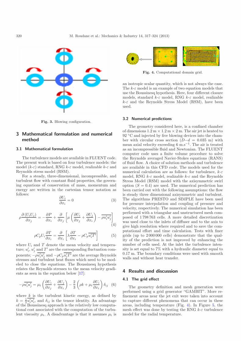
Fig. 4. Computational domain grid.
an isotropic scalar quantity, which is not always the case.The k-ε model is an example of two equation models thatuse the Boussinesq hypothesis. Here, four different closuremodels, standard k-ε model, RNG k-ε model, realizablek-ε and the Reynolds Stress Model (RSM), have beenused.
3.2 Numerical predictions
The geometry considered here, is a confined chamberof dimensions 1.2 m × 1.2 m × 2 m. The air jet is heated to92 ◦C and injected by five blowing devices into the cham-ber with circular cross section (D−d = 0.035 m) withmean axial velocity exceeding 6 m.s−1. The air is treatedas an incompressible fluid and Newtonian. The FLUENTcomputer code uses a finite volume procedure to solvethe Reynolds averaged Navier-Stokes equations (RANS)of fluid flow. A choice of solution methods and turbulenceare available in this CFD code. The models used for thenumerical calculation are as follows: for turbulence, k-εmodel, RNG k-ε model, realizable k-ε and the ReynoldsStress Model (RSM) model with the axisymmetric swirloption (S = 0.4) are used. The numerical prediction hasbeen carried out with the following assumptions: the flowis steady three dimensional axisymmetric and turbulent.The algorithms PRESTO and SIMPLE have been usedfor pressure interpolation and coupling of pressure andvelocity, respectively. The numerical simulation has beenperformed with a triangular and unstructured mesh com-posed of 1 798 763 cells. A more detailed discretizationwas used close to the inlets of diffuser and to the axis togive high resolution where required and to save the com-putational effort and time calculation. Tests with finergrids (up to 2 000 000 cells) demonstrate that the qual-ity of the prediction is not improved by enhancing thenumber of cells used. At the inlet the turbulence inten-sity is set equal to 7% with a hydraulic diameter equal to0.17 m. The boundary conditions were used with smoothwalls and without heat transfer.
4 Results and discussion
4.1 The grid effect
The geometry definition and mesh generation wereperformed using a grid generator “GAMBIT”. More re-finement areas near the jet exit were taken into accountto capture different phenomena that can occur in theseareas, including temperature (Fig. 4). In Figure 5, themesh effect was done by testing the RNG k-ε turbulencemodel for the radial temperature.

M. Roudane et al.: Mechanics & Industry 14, 317–324 (2013) 321
Fig. 5. Numerical solution independency of the grid.
4.2 Temperatures distribution
In this section we present the experimental and nu-merical results which are obtained by the temperature di-mensionless expression as follows: Tr = [T −Ta]/[T0−Ta],r/D and x/D respectively, where T is the jet tempera-ture, Ta is the ambient temperature and T0 is the maxi-mum temperature of the air blowing at origin. The radialand axial locations are given by reference to the diameterof the blowing orifice in dimensionless form r/D 1 to 10and x/D = 1 to 20.
The comparison of the calculated radial temperatureprofiles with the experimental results is given in Figure 6.We can noted that for station x/D = 1, the tempera-ture reaches its maximum near the center line, and thendecreases in away from this area until it stabilizes fromr/D = 3. In the station x/D = 5, we can see that thetemperature increases to its maximum near the pointr/D = 1, then it starts to decrease rapidly to the pointr/D = 3 and it stabilized after a low temperature varia-tion. The increase in temperature between the r/D = 0and r/D = 1 is due to the design of the swirler, becausethe periphery of the blow port is hotter than the centerthere of that justify the low temperature at the center ofthe jet. In the stations x/D = 9, x/D = 15, x/D = 18 andx/D = 20, we note that the temperature profiles are gen-erally in the same profiles. Generally, there is a low tem-perature homogenization near the inlet orifice and also atstation x/D = 5.
From the axial temperature profiles given in Figure 8and the radial profiles shown in Figure 6, we can con-clude that the interaction of jets reduces the amplitudeof the axial temperature, while ensuring a significantspread radial temperature. Therefore there is an increaseof the radial turbulence intensity. The homogenization oftemperature is almost perfect; confinement improves thequality of temperature stratification along the jet. There
is also an axial uniform temperature at all stations stud-ied (Fig. 8). Temperature profiles provided thermal sta-bility and remarkable spread. By analyzing Figure 9, wesee that the number of peripheral jets ensures a more ho-mogenization compared to a single swirling jet.
For this jet configuration, it could seem interesting toexamine the changes made by different turbulence mod-els. An examination of Figures 7 and 8, which show thetemperature profiles at several radial and axial distances,shows that the difference in the numerical solution is re-ally minimal.
The temperature profiles obtained with different tur-bulence models and mesh refinements are compared to theexperimental data. We can see that the RNG k-ε modelgives the best overall results with an average error of 4.5%with the experimental (Fig. 7). The realizable K-ε modelis also achievable to obtain a reasonable prediction awayfrom the jet axis; on the contrary, the RSM model givesa prediction acceptable near the jet axis.
5 Conclusion
This study showed the following results:
– The use of a multiple swirling jet provides temper-ature profiles fairly regular, and therefore significantthermal homogenization.
– In the radial direction, the temperature is more impor-tant for the multiple swirling jets that for the singleswirling jet.
– Confinement improves the quality of temperaturestratification along the jet.
– The temperature decreases less rapidly compared to asingle swirling jet.
– The multiple swirling jets provide in all cases, for agiven station a better thermal stability and a signifi-cant growth compared to a swirling single jet.

322 M. Roudane et al.: Mechanics & Industry 14, 317–324 (2013)
Fig. 6. Radial temperature profile for a confined multiple swirling jet.
Fig. 7. Histogram of errors quantification between numerical and experimental results.

M. Roudane et al.: Mechanics & Industry 14, 317–324 (2013) 323
Fig. 8. Comparison of the axial temperature distribution of the multiple swirling jet with the experimental results.
Fig. 9. Comparison of axial temperature profiles of single and multiple swirling jet (experimental results).
Fig. 10. Contours of static temperature (K).

324 M. Roudane et al.: Mechanics & Industry 14, 317–324 (2013)
All these features show the importance of the applicationof this type of jet in heating and space cooling comparedto conventional jet system.
We can also conclude that the RNG K-ε model is validfor the prediction of low turbulent swirling jets, it can bet-ter predict the flow compared to other models. The modelpresented for excessive levels of turbulent diffusion. Notethat it gives a correct representation of flow characteris-tics by comparing these results with experimental data.
To operate virtually results of this work with a viewto their application delivery devices in air ventilation sys-tems, it is recommended to also determine the velocityprofiles of the different configurations of the jets, the pres-sure distribution, heat exchange and the influence of thegeometry and positioning of the discharge openings onthe thermal homogenization.
References
[1] J. Panda, D.K. McLaughlin, Experiments on the insta-bilities of a swirling jet, Phys. Fluids 6 (1994) 263–276
[2] J.M. Beer, N.A. Chigier, Swirling flow in combustionaerodynamics, Krieger, Malabar, Florida, 1972
[3] M.P. Escudier, J. Keller, Recirculation in swirling flow:a manifestation of vortex breakdown, AIAA J. 23 (1985)111–116
[4] W. Leuckel, N. Fricker, The characteristics of swirl-stabilized natural gas flames Part I: Different flame typesand their relation to flow and mixing patterns, J. InstituteFuel S (1976) 103–112
[5] H.J. Sheen, W.J. Chen, S.Y. Jeng, T.L. Huang,Correlation of swirl number for a radial type swirl gener-ator, Exp. Therm. Fluid Sci. 12 (1996) 444–451
[6] L. Thielen, K. Hanjalie, H. Janker, R. Manceau,Predictions of flow and heat transfer in multiple imping-ing jets with an elliptic blending second moment closure,Int. J. Heat Mass Transfer 48 (2004) 1583–1598
[7] M. Rady, E. Arquis, Heat transfer enhancement of multi-ple impinging slot jets with symmetric exhaust ports andconfinement surface protrusions, Appl. Therm. Eng. 26(2005) 1310–1319
[8] A. Bouziane, A. Khalfi, S. Laouedj, M. Aminallah,Simulation numerique d’un ecoulement reactif swirle partrois modeles de turbulence, 17eme congres francais demecanique, Troyes, 2005
[9] M. Braikia, L. Loukarfi, L. Djafer, Caracterisation ther-mique d’un systeme multi jets rotationnel, 17eme CFM,Troyes, 2005
[10] A. Aroussi, S. Kucukgokoglan, S.J. Pickering, M.Menacer, Evaluation of four turbulence models in theinteraction of multi burners swirling, 4th Internationalconference on multiphase flow, New Orleans, Louisiana,USA, 2001
[11] H. Elbanna, A. Sabbaghj, Interaction of two nonequaljets, A.I.A.A J. 24 (1986) 686–687
[12] T. Kazuya, T. Miyako, L.W. Peter N. Kazuyoshi Swirland buoyancy effects on mixing performance of baffle-plate-type miniature confined multijet, Int. J. Heat FluidFlow 31 (2010) 45–56
[13] S. Hirai, T. Takagi, T. Higashia, Numerical prediction offlow characteristics and retardation of mixing in a turbu-lent swirling flow, Int. J. Heat Mass Transfer 32 (1989)121–130
[14] Z.D. Protic et al., Novel Methods for Axial Fan ImpellerGeometry Analysis and Experimental Investigations ofthe generated Swirl Turbulent Flow, Therm. Sci. 14(2010) 125–139
[15] A.K. Gupta, D.G. Lilley, N. Syred, Swirl Flows, AbacusPress, London, 1984
[16] Y. Huang, V. Yang, Dynamics and Stability of Lean-Premixed Swirl-Stabilized Combustion, Progr. EnergyCombus. Sci. 35 (2009) 293–364
[17] FLUENT User’s Guide, 2006