Embed Size (px)
Citation preview
Department of Mechanical Engineering TKM College of Engineering Kollam,
Kerala-691005, India
Abstract - Self-pressurization phenomenon is one of the most important problems in the storage of cryogenic liquid. Self-pressurization, as a result of vaporization can occur in many scientific and technical applications like cryogenic storage tanks, pressurized water reactors etc. it has been difficult to predict the behavior of cryogens during self-pressurization process due to its complex non-equilibrium thermal behavior. In this paper, self -pressurization studies are conducted on a generalized CFD model and the behavior is analyzed. Here the heat inleak through the insulation is calculated and applied as boundary condition. The studies are conducted by varying the layer of insulation, and the pressurization behavior is analyzed. For modeling, meshing & analysis ANSYS 14.5 CFD software is used. Transient studies are conducted using VOF model and results are discussed.
Keywords - storage tanks, VOF, self-pressurization
Nomenclature
T - Temperature
E - Energy
- Density
– Dynamic viscosity
keff - Effective thermal conductivity
Sh - Source term
v - Velocity
1. Introduction
The phase change associated with heat transfer is a complex phenomenon, prediction of both the heat transfer and mass transfer along the interface is a difficult task due to the difference in the
properties and the associated parameters on the either side of interface
An accurate prediction can be done with computational model about the transient interface phenomenon due to mass transfer coupled with phase change due to evaporation. Winter et al [1]The objective of research is to develop a complete finite volume based Computational Fluid Dynamic (CFD) model of tank pressurization in reduced gravity using an Energy of Fluid (EOF) approach, and to use the simulation to aid in the design and prediction of propellant management technologies aimed at controlling tank pressurization. Jaeheon sim et al [2] The main focus of the study is to improve the accuracy of the sharp solid boundary treatment and to implement a phase change model. The energy and mass transfer across the interface due to phase change is computed from Stefan condition using probe-based temperature gradient computations. The self-pressurization in a liquid hydrogen fuel tank is simulated and it is shown that the conduction-only solution underestimates the pressure rise, and the full Navier-Stokes and energy equation solution is required to study liquid fuel tank pressurization due to the influence of transport phenomena. C.K. Krishnaprakas, Badari Narayana and Pradip Dutta in 2000[3] evaluated four different empirical models for heat transfer are by fitting against experimentally observed heat flux through MLI blankets of various configurations, and the results are discussed. Aydelott [4] investigated tank self-pressurization in a small-scale partially filled liquid hydrogen container in both low gravity and normal gravity. He showed that tank geometry and size, heat transfer rate and distribution, liquid fill fraction and gravity level all affect the rate of pressure rise in a closed cryogenic container.Li Chen, Yuguo Lia in 1998 [5]a numerical model for two-phase flows with a varying density is presented, in which a modified volume of fluid (VOF) method is combined with a semi-implicit algorithm (simple). Several related works [6-10] by various investigators reveal the importance of using accurate property values for theoretical and numerical analysis.
2. Self pressurization phenomenon
Self pressurization can be explained detail with the help of Fig 1 shown below it consist of a tank partially filled with a liquid and rest is for the vapor of the same .
International Journal of Scientific & Engineering Research, Volume 5, Issue 7, July-2014 ISSN 2229-5518 897
IJSER © 2015 http://www.ijser.org
IJSER

Fig 1: Partially filled Spherical tank
we can define it as two control volume the interface between the two is a thin layer which allows the surface vaporization and heat transfer between the liquid and vapor here the heat inleak through the insulation is carried to the interface by natural convection due to continuous heat inleak evapourisation occur at interface resulting in ullage compression and subsequent pressure rise in the tank
3. CFD modelling
With the advancement and recent development of CFD codes, a full set of fluid dynamic and multiphase flow equations can be solved numerically. The current study used commercial CFD code, ANSYS FLUENT, to solve the balance equation set via domain discretization, using control volume approach. These equations are solved by converting the complex partial differential equations into simple algebraic equations. An implicit method for solving the mass, momentum, and energy equations is used in this study. The kturbulence model with standard wall functions used due to their proven accuracies in solving multiphase problems . Effect of normal gravitational acceleration of is included
3.1 Governing Equations
3.1.1 Mass conservation in three dimensions
Rate of increase of mass in fluid element = Net rate of flow of mass into element
0)()()(zw
yv
xu
t
3.1.2 Momentum Equation
A single momentum equation is solved throughout the domain, and the resulting velocity field is shared among the phases. The momentum equation, shown below, is dependent on the volume fractions of all phases through the properties and .
3.1.3 Energy Equation
The energy equation, also shared among the phases, is shown below.
3.2 Geometry and boundary conditions
Usually cylindrical vessel are used for cryogenic liquid storage, cylindrical vessel of 10cm diameter and 10cm height filled with 70% of liquid hydrogen as shown in Fig 2 is used for simulation the remaining 30% of the tank ullage volume is filled with hydrogen vapour. since the domain is axisymmetric about vertical axis axisymmetric approach is justified. Here the cylinder is insulated with Multilayer insulation and heat in leak through the different layers of MLI is calculated and applied as boundary condition. Initially the pressure patched to101325 Pa, and phase interactionswere enabled. Geometry is modelled in ANSYS 14.5 and tetrahedral meshing is used , A total of 75000 cells are present
Fig 2: Modelled geometry filled with 70% LH2
The applied Heat flux for the different layers of MLI for hydrogen are calculated from the equations are given below
Table 3.2.1: Heat flux for different layers of MLI
Sl no
Number of layers Heat flux (W/m2)
1 20 2
2 30 1.4
3 40 1
4 50 .8093
The calculated heat fluxes are applied on the all surfaces of the cylinder.
3.3 Modelling multi-phase
The numerical simulations presented in this work are based on the ANSYS FLUENT volume-of-fluid (VOF),which is a Euler-Euler two fluid model method. The Eulerian modeling is based on mass-weighted averaged mass and momentum transport equations for all phases, gas and liquid. The VOF model is designed for two or more immiscible fluids in which the position of the interface between the fluids is of interest. In the VOF model, a single set of momentum
International Journal of Scientific & Engineering Research, Volume 5, Issue 7, July-2014 ISSN 2229-5518 898
IJSER © 2015 http://www.ijser.org
IJSER
equations is shared by the fluids, and the volume fraction of each of the fluids in each computational cell is tracked throughout the domain. One set of Navier-Stokes equations for the gas-liquid mixture together with two volume fraction equations and turbulence model equations are solved in this model. Transport equations are used to track the motion of liquid–vapour boundary and both the phases share a common velocity field. VOF method in conjunction with evaporation–condensation mass transfer model has been used to simulate mass transfer by phase change. The liquid-vapour mass transfer is governed by the vapour transport equation
3.4 Modelling assumption
The flow is assumed to be transient, and the pressure based solver is used. Standard wall functions have been selected and the effect of drag, lift and slip interaction has not been investigated. Initially it is assumed that ullage volume is completely filled with vapor and the liquid zone is completely filled with Liquid Hydrogen.
3.5 Solution strategy and convergence
Self-pressurization due to evaporation is inherently transient. Transient analysis is carried out with a time step of 0.0001 seconds. A first order upwind discretization scheme is used for the momentum equation, volume fraction, energy, turbulence kinetic energy and specific dissipation rate. First order implicit transient formulation is used. The convergence criterion is based on the residual value of the calculated variables, i.e., mass, velocity components, energy, turbulence kinetic energy, turbulence dissipation rate and volume fraction. In pressure-velocity coupling, coupled pressure velocity coupling scheme is used. The coupled algorithm solves the momentum and pressure-based continuity equations together. Other solution strategies used are the reduction of under relaxation factors of momentum, the volume fraction, the turbulence kinetic energy and the turbulence dissipation rate.
4. CFD Analysis and Results
4.1 Comparison of the code
Pressurization in liquid hydrogen tank investigated by Jaeheon Sim et al. [2] is used for comparison. A 50% filled liquid hydrogen vessel is heated uniformly on all its sides. Self pressurisation due to evaporation occurs as a result of the heat flux. As reported in the paper the saturation pressure after 1000 seconds and 2000 seconds is 101750 and 102350 Pascal respectively.
4.2 Results and Discussions 4.2.1 Hydrogen with 20 layers of MLI
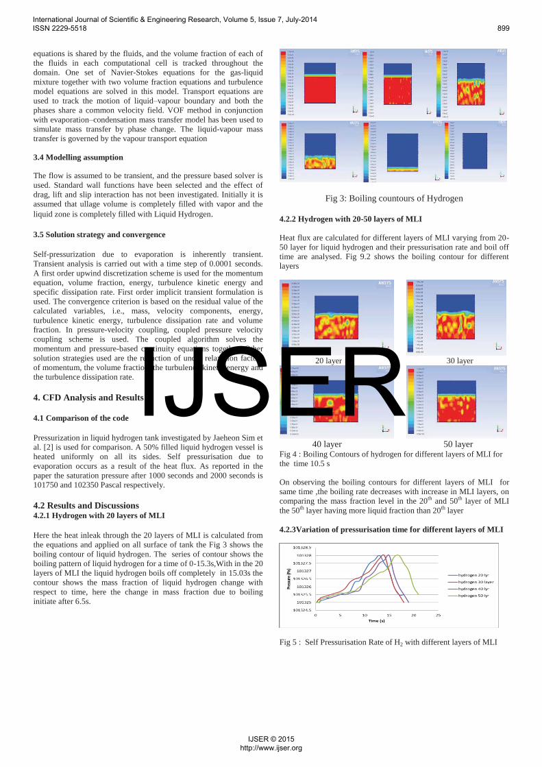
Here the heat inleak through the 20 layers of MLI is calculated from the equations and applied on all surface of tank the Fig 3 shows the boiling contour of liquid hydrogen. The series of contour shows the boiling pattern of liquid hydrogen for a time of 0-15.3s,With in the 20 layers of MLI the liquid hydrogen boils off completely in 15.03s the contour shows the mass fraction of liquid hydrogen change with respect to time, here the change in mass fraction due to boiling initiate after 6.5s.
Fig 3: Boiling countours of Hydrogen
4.2.2 Hydrogen with 20-50 layers of MLI
Heat flux are calculated for different layers of MLI varying from 20-50 layer for liquid hydrogen and their pressurisation rate and boil off time are analysed. Fig 9.2 shows the boiling contour for different layers
20 layer 30 layer
40 layer 50 layer Fig 4 : Boiling Contours of hydrogen for different layers of MLI for the time 10.5 s
On observing the boiling contours for different layers of MLI for same time ,the boiling rate decreases with increase in MLI layers, on comparing the mass fraction level in the 20th and 50th layer of MLI the 50th layer having more liquid fraction than 20th layer
4.2.3Variation of pressurisation time for different layers of MLI
Fig 5 : Self Pressurisation Rate of H2 with different layers of MLI
International Journal of Scientific & Engineering Research, Volume 5, Issue 7, July-2014 ISSN 2229-5518 899
IJSER © 2015 http://www.ijser.org
IJSER

It is observed from the graph (Fig 5) that pressurisation rate achieved for different layers of MLI for Hydrogen is same 101328 Pa, thepressurisation rate is high when the liquid mass fraction is nearly 3/4th of the total liquid mass fraction, and the decrease in the boil off time for different MLI layer is visible in the graph
4.2.4 Mass fraction of Hydrogen for different MLI layers
Fig 6 : Variation of mass fraction phase1 with time for different layers of MLI
It is observed from the graph (Fig 6) the mass fraction changes from 1 - 0 within a time period of 15.3 seconds for 20 layer of MLI and for the 50 Layer of MLI it is 20.05s, so by increasing the layers of MLI will decrease the boil off time .on comparing the mass fraction for the 20th and 50th layer for a time of 10s it will be .5 for 20th layer and .987 for 50th layer
4.2.5 Heat transfer coefficient with time
Fig 7 :Variation of heat transfer coefficient with time for 20th and 50th layer
It is observed from the graph that the heat transfer coefficient decreases up to the sensible heating of vapor on the upper domain of the cryogen tank and after it increases with respect to the boiling rate .Here the heat transfer coefficient is higher for the 50th layer than for the 20th layer, it is due to the low bulk fluid temperature
5. Conclusion and scope for future work
In the case of hydrogen by increasing number of MLI layers the boil off time can be decreased. A difference of 180W/m2K is noted on the heat transfer coefficient for 20th and 50th layer of hydrogen for
a time of 12s. The same analysis can be conducted by varying the geometry of the cryogen tank. By changing the ullage volume for vapor ,analysis can be conducted
Acknowledgement
The authors gratefully acknowledge the Department of Mechanical Engineering, TKM College of Engineering, Kollam, for availing the facilities at CFD Lab, which helped to complete the work successfully
[1] A P Winter and J G Marchetta 2010 “Simulating Self-Pressurization in Propellant Tanks”48th AIAA Aerospace Sciences Meeting Including the New Horizons Forum and Aerospace Exposition 4 - 7 January 2010, Orlando, Florida.
[2]Jaeheon Sim and Chih-Kuang Kuan 2011 “Simulation of Spacecraft Fuel Tank Self-pressurization Using Eulerian-Lagrangian Method” 49th AIAA Aerospace Sciences Meeting including the New Horizons Forum and Aerospace Exposition 4 - 7 January 2011, Orlando, Florida
[3]C.K. Krishnaprakas , K. Badari Narayana and Pradip Dutt, Heat transfer correlations for multilayer insulation systems, Cryogenics 40 (2000), p. 431-435
[4]Aydelott, J.C., "Effect of gravity on self-prcssurization of spherical liquid- hydrogen tankage," NASA-TN-D-4286, 1967
[5] Li Chen and Yuguo Li, A numerical method for two-phase flows with an interface, Environmental Modelling & Software 13 (1998) 247-255
[6] J. A. Demko, J. E. Fesmire and S. D. Augustynowicz, Design tool for cryogenic thermal insulation systems, Advances in cryogenic engineering: transactions of the cryogenic Engineering conference-CEC, Vol. 53 p 145-153
[7]E.H. Kennard, Kinetic theory of gases, McGraw-Hill Book Co., 1938.
[8]George P. Sutton and Oscar Biblarz, Rocket Propulsion Elements,: an introduction to the engineering of rockets 8th Edition, ISBN: 978-0-470-08024-5
[9]James E. Fesmire and Stan D. Augustynowicz, Cryogenic Thermal insulation systems, Proc. of 16th Thermal and Fluids Analysis Workshop, Orlando , Florida August 9, 2005
[10] Jaeheon Sim, Chih-Kuang Kuan and Wei Shyy, Simulation of Spacecraft Fuel Tank Self-pressurization Using Eulerian-Lagrangian Method, 49th AIAA Aerospace Sciences Meeting including the New Horizons Forum and Aerospace
International Journal of Scientific & Engineering Research, Volume 5, Issue 7, July-2014 ISSN 2229-5518 900
IJSER © 2015 http://www.ijser.org
IJSER