Embed Size (px)
Citation preview

Research ArticleNumerical Investigation on the Effects ofStructural Parameters of Labyrinth Cavity onSealing Performance
Jianmei Feng Lingzi Wang Hang Yang and Xueyuan Peng
School of Energy and Power Engineering Xirsquoan Jiaotong University Xirsquoan 710049 China
Correspondence should be addressed to Jianmei Feng jmfengxjtueducn
Received 8 April 2018 Revised 19 June 2018 Accepted 2 July 2018 Published 19 July 2018
Academic Editor Sandro Longo
Copyright copy 2018 Jianmei Feng et al This is an open access article distributed under the Creative Commons Attribution Licensewhich permits unrestricted use distribution and reproduction in any medium provided the original work is properly cited
This paper presents a study on the leakage characteristics of a labyrinth piston compressor A computational fluid dynamics modelwas applied to predict the effects of different structural parameters of the labyrinth seal on the sealing performance The velocityfield through the sealing clearance and labyrinth cavity was demonstrated and analyzed An experimental rig was built to validatethe simulation model and the results of the simulation and experimental data showed a good agreement The effects of the cavitywidth cavity depth tooth thickness and clearance of the seal on the leakage characteristics were discussed in detail The resultsshowed that except for the significant influence of the labyrinth clearance 119889120575 (the ratio of cavity depth to labyrinth clearance)should be bigger than 27 to achieve the minimum leakage flow and the effect of the varied cavity width can be ignored Moreoverwhen the piston length and cavity width remain constant the thinner the tooth thickness the greater the number of labyrinthcavities that can be arranged and the higher the sealing performance achieved
1 Introduction
In the labyrinth piston compressor shown in Figure 1 anoncontact labyrinth seal was used between the piston andcylinder wall as well as between the piston rod and packingThe annular labyrinth grooves were machined around thepiston piston rod and cylinder wall and as indicated in thesectional view there are many small cavities on the two sidesof the tiny labyrinth channel In the compressor the internalleakage is the main source of leakage rather than externalleakage and thus the labyrinth structure on the piston hasbeen mostly discussed
By using a labyrinth seal instead of a piston ring the recip-rocating compressor has many advantages such as oil-freegas compression and transport nonlubricated maintenanceand no friction loss A labyrinth piston compressor can pro-vide environmentally friendly products as high purity gasesand can be widely used in various industries [1] However thewider application of labyrinth piston compressors has beenlimited because they show a worse sealing performance com-pared to traditional compressors which have piston rings
Thus studying the influence of the structural parameters ofa labyrinth seal has a great significance in optimizing thesealing performance in labyrinth piston compressors
As early as in 1908 Martin [2] began studying the massflow rate in a labyrinth gap and over the following 50 yearsdifferent types of analytical calculationmethods of a labyrinthseal flow were explored [3ndash6] In the late twentieth century aseries of experimental and numerical studies were carried outto investigate the labyrinth mechanism in rotating machinery[7ndash9] Later many researchers began continuously enrich-ing the labyrinth used in rotating machinery and by thebeginning of the 21st century valuable research results on thelabyrinth seal in rotating machinery began being published[10ndash14]
Wang et al [15] simulated the distribution of a static flowfield on two kinds of seals and their results showed that astepped labyrinth is more efficient than an interlocking sealSuryanarayanan and Morrison [16ndash18] studied the relation-ship between the flow coefficient and transmission coefficientinside the labyrinth channels in detail and the influence ofthe tooth type compression ratio clearance and Reynolds
HindawiMathematical Problems in EngineeringVolume 2018 Article ID 5273582 12 pageshttpsdoiorg10115520185273582
2 Mathematical Problems in Engineering
Figure 1 A typical labyrinth piston compressor
number were obtained Kim andCha [19] combined the com-putational fluid dynamics (CFD) method and a theoreticalanalysis to discuss the influence of the structural arrangementand pressure ratio on the sealing efficiency and found thata stepped labyrinth seal is more efficient when the labyrinthclearance is larger Bozzi et al [20] performed amore detailedanalysis on the heat transfer in a labyrinth seal Pugachev etal [21 22] used a CFD model to research the direction ofthe main vortex in a short chamber with a backward-facingstep and numerically and experimentally verified that thesegmentation negatively affects the leakage performance andstiffness coefficients of the brush-labyrinth sealing configu-ration Yuan et al [23] established a CFD model to optimizethe seal design for supercritical carbon dioxide in turboma-chinery and the model was then confirmed based on theexperimental results
The majority of studies on labyrinth seals are concen-trated on rotating machinery whereas very few studies havetargeted the labyrinth piston compressors directly Becausethe piston only does reciprocating motion and is shapedlike a column many of the conclusions that were drawnfrom rotating machinery are no longer suitable for labyrinthpiston compressors For example the stepped labyrinth sealwhich is proved to be more efficient than the straight seal isunsuitable for application in reciprocating compressors
Effectively controlling the gas leak is a serious and difficulttechnical problem for the labyrinth piston compressor Toguide the design of a labyrinth seal in the compressors de-termining the influence of the structural parameters of alabyrinth on the sealing performance is important In thisstudy the effects of various structural parameters such as thelabyrinth clearance the width and depth of the labyrinthcavity and the number of labyrinth cavities were numericallyinvestigated and the simulation method was verified experi-mentally
2 Simulation Method
21 Geometrical Model According to Meng and Xia [24]isosceles trapezoid and triangle shaped cavities achieve the
Figure 2 Simplified model
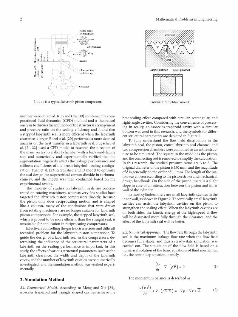
best sealing effect compared with circular rectangular andright-angle cavities Considering the convenience of process-ing in reality an isosceles trapezoid cavity with a circularbottom was used in this research and the symbols for differ-ent structural parameters are depicted in Figure 2
To fully understand the flow field distribution in thelabyrinth seal the piston entire labyrinth seal channel andtwo compression chambers were combined as an entire struc-ture to be simulated The square in the middle is the pistonand the connecting rod is removed to simplify the calculationIn this research the studied pressure ratios are 3 to 8 Theoriginal diameter of the piston is 150 mm and the magnitudeof 120575 is generally on the order of 01 mmThe length of the pis-tonwas chosen according to the piston stroke andmechanicaldesign handbook On the side of the piston there is a slightslope in case of an interaction between the piston and innerwall of the cylinder
In most cylinders there are small labyrinth cavities in theinnerwall as shown inFigure 2Theoretically small labyrinthcavities can assist the labyrinth cavities on the piston tostrengthen the sealing effect When the labyrinth cavities areon both sides the kinetic energy of the high-speed airflowwill be dissipated more fully through the clearance and theeffect of the labyrinth seal will be better
22 Numerical Approach Theflow rate through the labyrinthseal is the maximum leakage flow rate when the flow fieldbecomes fully stable and thus a steady-state simulation wascarried out The simulation of the flow field is based on anumerical solution of the basic equations of fluid mechanicsie the continuity equation namely
120597120588120597119905 + nabla sdot (120588997888rarrV ) = 0 (1)
The momentum balance is described as
120597 (120588997888rarrV )120597119905 + nabla sdot (120588997888rarrV 997888rarrV ) = minusnabla119901 + nabla120591 + 997888rarr119878 (2)
Mathematical Problems in Engineering 3
Figure 3 Boundary conditions
The energy conservation equation is
120597 (120588119879)120597119905 + nabla (120588997888rarrV119879) = ℎ
119888119901Δ119879 minus nabla119902 (3)
To consider the compressibility of the gas the airflow isassumed to comply with the ideal gas law and thus the stateequation is as follows
119901 = 120588119877119879 (4)
In the labyrinth channel when the fluid flows throughthe tiny clearance to the cavity a swirl flow will form In therealizable 119896 minus 120576model the coefficient used in calculating theturbulent viscosity was correlated with the strain rate ratherthan a constant [25] and thus was approved to be suitableto simulate a swirl flow In this research the realizable 119896 minus 120576model is used to compute the turbulence transport contribu-tion
The boundary settings are illustrated in Figure 3The out-let pressure was continuously set to the ambient pressure 01MPa the high inlet pressure varied from 03 to 08 MPa andthus the pressure ratios were 3 to 8 The outlet temperaturewas the ambient temperature 300 K and the temperature ofthe inlet was set to the true temperature discharged from theair source compressor The cylinderrsquos outer wall made directcontact with the cooling water which circulated in a timelymanner and removed the heat from the cylinder wallinstantly The flow of the water circulation was significantand the flow rate could be adjusted thus the discharge gastemperature was generally 310 to 330 K when the pressureratio changed from 3 to 8 and the temperature of the outerwall of the cylinder was usually kept at 300 K or almostthe same temperature as the cooling water The turbulentintensity (5) and hydraulic diameter (half of the cylinderdiameter) were defined at the inlet boundary
Because the physical model is symmetrical on two sidesthe computation model takes the half of region The velocityis set as zero on the symmetrical wall and the other physical
quantities are completely symmetric It can be expressed asbelow
1206011119869 = 1206012119869 (5)
The model equations were discretized with the finitevolume method The pressure-velocity field was obtained byemploying the SIMPLE algorithm and the approximation ofstate variables is realized by a second-order upwind scheme
23 Grid Independence Verification As shown in Figure 4in the labyrinth compressor the cylinder wall and thecompressor chambers are of different orders in terms ofsize with that of the labyrinth structure A two-dimensionalunstructured grid for the labyrinth and compression chamberwas generated A triangle mesh was used in the labyrinth sealpart to fit the labyrinth cavity which had a triangular shapewhereas in the parts of the cylinder wall and compressionchambers which had rectangular shapes bigger sized quadri-lateral elements were applied
The difference in scale of the flow field can be presentedby setting the mesh scale of the two chambers to 10 timesbigger than that of the clearance and a rapid convergence inthe calculation could also be achieved
Table 1 shows the comparison results of different meshsizes The ldquosizerdquo in the first column indicates the grid sizeof the two compression chambers When the grid sizes were1 and 05 mm the mass flow rate of the leakage was muchsmaller than at 01 mm When the mesh size became largerthan 02 mm the number of total elements was only about25 of the 01 mm case whereas the leakage mass flow wasonly 02 lower Therefore considering the simulation timeand accuracy 02 mm was chosen for the mesh size of thecompression chamber whereas for the labyrinth seal themesh size was set to 002 mm
3 Validation Experiment
The static labyrinth compressor test rig shown in Figure 5was built to verify the feasibility of the simulation method
4 Mathematical Problems in Engineering
Figure 4 Division of the flow field
Figure 5 Test system
Figure 6 Test bench
First the air source compressor was started which wouldcompress the air to about 10MPa After the air pressure in thestorage tank became stable valve 1 and valve 2 were regulatedto adjust the inlet pressure Figure 6 shows an image of the realexperimental section and Figure 7 shows a sectional view ofthe test apparatus
In the experimental section the gas flowed into thebottom orifice following the direction of the arrows entered
Figure 7 Schematic of labyrinth configuration
Table 1 Mesh independence test
Grid sizemm Total elements Mass flow of leakagetimes10minus2 kgsdotsminus11 80018 1530905 268760 1587502 1551123 1598301 6146194 16060
through the labyrinth seals and then flowed out When thegas exited from the test section it went into the gasholderand then flowed through the nozzle flow meter Finally thegas was discharged into the environment When the entiresystem became stable the value of the suction temperaturethe difference in water column height the nozzle upstreamgas temperature and the environmental pressure could bemeasured to calculate the leakage flow rate
The uncertainty of the test results mainly comes fromthe systematic errors of the acquisition and measurementequipment According to the error of the nozzle flow meterthe relative error of the leakage mass flow rate is 251
Mathematical Problems in Engineering 5
Figure 8 Comparison of the experimental data and the simulationresults
4 Results Discussion
41 Model Validation Figure 8 indicates that the leakagemass flow rate of the experimental data and the simulatedresults show a proportional increase with an increase in thepressure ratio when the other conditions are the same how-ever the measured leakage mass flow rate was generally high-er than the simulated value
The difference mainly came from the measurement errorduring the experiments and the accuracy of the manu-factured labyrinth cavities was lower than the ideal valueset in the model thus the measured leakage was slightlyhigher Both the experimental and the simulated results ofthe labyrinth leakage show a strong linear dependency withan increase in the pressure ratio and have almost the sameslope The relative error between the experimental data andsimulated results was less than 10 and thus the simulationmethod was shown to be reasonable
42 Distribution of Pressure and Temperature To reveal theleakage characteristics along the clearance a horizontal line119883119891 was set in the middle of the labyrinth clearance as shownin Figure 4 The pressure and temperature along 119883119891 weremonitored the results of which are demonstrated in Figure 9(120575 = 015 mm119908 = 15 mm 119889 = 10 mm 119905 = 05mm) when thepressure ratio was 3 In the labyrinth clearance the pressuredecreased gradually and from the inlet to the outlet thepressure increasingly decreased indicating that the sealingeffect of the labyrinth became increasingly significant
It can also be seen that the temperature oscillates withgradually greater amplitudes from the inlet to the outlet ofthe labyrinth clearanceThis can be attributed to the dramaticincrease in speed of the high-pressure fluid going through thetiny labyrinth clearance and the corresponding decrease inthe pressure of the fluid At the same time its internal energydrops and the temperature of the fluid rapidly decreasesSubsequently when the fluid reaches the labyrinth cavity
which has an abruptly increased flow space a vortexwill formowing to the shape of the cavity as shown in Figures 10(b)10(c) and 10(d) and thus the fluid velocity will suddenlydecrease Because the time of the entire process is too shortto include the heat transfer when the fluid arrives at the nextlabyrinth cavity its temperature will recover to the originalvalue Therefore in the labyrinth seal the seal effect becomesincreasingly significant that is the drop in temperature in thelabyrinth seal will increase and the kinetic energy dissipationfunction of the labyrinth cavity will be increasingly clearer
From Figure 10 we can see that for every labyrinth be-tween two chambers because the outlet pressure is only 2 barlower than the inlet pressure the flow within the entire laby-rinth seal is subsonic
43 Comparison of Different Cylinder Walls The dischargecoefficients of compressors having cylinder walls with andwithout labyrinth cavities respectively were compared underdifferent pressure ratios the results of which are shown inFigure 11 Consistent with the theoretical analysis the sealingperformance of a cylinder with labyrinth cavities was betterthan that of a smooth cylinder whose discharge coefficientwas about 25 higher on average
Because the small labyrinth cavities on a cylinder aredifficult to fabricate many labyrinth compressors only have alabyrinth on the piston which is also the dominating sealingpart In further research and calculation only the structuresof a labyrinth cavity on the piston were considered and thusthe inner surface of the cylinder was a smooth wall without alabyrinth cavity to simplify the calculation (Figures 3 and 4)
44 Effects of Labyrinth Cavity Parameters
441 Discharge Coefficient The discharge coefficient refersto the ratio of the actual flow to the ideal flow through aspecific channel It is a dimensionless quantity and is oftenused to describe the sealing efficiency [7 16ndash19 26ndash29]
119862119889 = 119898119903119890119886119897119898119894119889119890119886119897 (6)
In (6) 119898119903119890119886119897 is the real leakage mass flow rate obtainedthrough the experiments or numerical simulation and119898119894119889119890119886119897indicates the theoretical mass flow rate for isentropic condi-tions
119898119894119889119890119886119897 = 120588119890V119890119860119890 = 119860119890 (12058801199010)12 (2 119896119896 minus 1)
12
sdot [(11990111199010)2119896 minus (11990111199010)
(119896+1)119896]12
(7)
Here 119860 is the cross-sectional area at the outlet of thechannel 1205880 and 1199010 are the density and static pressure at theinlet of the flow channel and 119901119890 is the static pressure at theoutlet of the flow channel and 119896 is the adiabatic coefficient ofthe working medium The smaller the discharge coefficientthe better the labyrinth seal performance
6 Mathematical Problems in Engineering
(a) Pressure along119883119891 (b) Temperature along 119883119891
Figure 9 Pressure and temperature distribution
(a) Pressure drop in the labyrinth seal
(b) Velocity field ofA (c) Velocity field ofB
(d) Velocity field ofC
Figure 10 Pressure drop and velocity fields in the labyrinth seal
Mathematical Problems in Engineering 7
Figure 11 Comparison of two cylinder walls
Figure 12 Discharge coefficient versus the labyrinth clearance
442 Clearance In this study 120575 varied from 009 to 035mm Figure 12 shows that the discharge coefficient 119862119889 hasalmost a linear growth with an increase in 120575 The value of 119862119889increased to two times that of the original when 120575 increasedto 026 mm indicting the significant effect of the clearanceon the sealing performance This can be attributed to the factthat when the fluid flows continuously through the labyrinthchannels a throttling occurs and the pressure drops rapidlyat every tiny labyrinth clearance segment The smaller thelabyrinth clearance 120575 is the stronger the throttling effect iswhich results in a larger pressure drop when the fluid flowsthrough the labyrinth clearance
Moreover as shown in Figure 13 the fluid on the top ofthe labyrinth cavity entered into the next seal directly ratherthan into the labyrinth cavity where the kinetic energy willbe dissipated and thus the sealing efficiency under a widerclearance will be worse120575 is unable to be unlimitedly narrowed in a real appli-cation owing to the assembly feasibility and thus achievingthe minimum value within the reasonable scope is of great
importance for sealing For reciprocating labyrinth pistoncompressors in a real application the labyrinth clearanceshould be no less than 01 mm or a direct contact betweenthe piston and cylinder wall could occur and the inner wallof the cylinder and the piston wall will both be destroyed
443 Number of Labyrinth Cavities If the total length ofthe labyrinth clearance is constant the tooth thickness 119905 willdirectly influence the number of labyrinth cavities on thepiston Let the size and shape of the labyrinth cavity remainthe same and then decrease 119905 from 150 to 01mm the numberof labyrinth cavities will then increase from 0 to 62 with aconstant uniform distribution on the piston
Figure 14 illustrates that with an increase in the numberof labyrinth cavities to 62 119862119889 decreases gradually by around36Theminimum value of 119905was 01 mm the correspondingcavity numberwas 62 and the discharge coefficientwas 0259when the maximum thickness was 150 mm no labyrinthcavities were present on the piston and 119862119889 was 0409 Onaverage one added cavity will lead to about a 058 decreasein 119862119889444 Cavity Width The labyrinth cavity studied consists oftwo sloping edges and a circular groove at the bottom of thecavity as shown in Figure 15The effects of the cavity width onthe leakage characteristics were investigated by changing thecircle radius of the bottom groove to allow the cavity width toldquozoom outrdquo or ldquozoom inrdquo as shown in Figure 16
When the value of119908120575 changed from8 to 14 the variationof119862119889 was as shown in Figure 17With the increase in119908120575 119862119889increased slightly from 0287 to 0301 which is only 488that is the labyrinth leakage rate increased very slightly Thevelocity fields for 119908120575 = 8 and 14 are shown in Figure 18When the depth of the labyrinth cavity was the same thelarger width led to a larger cavity and thus the flow vortex wasmore drastic Nevertheless the larger the cavity width thesmaller the number of cavities when thewhole length coveredfor the labyrinth seal in the piston was the same and thus intotal compared with the effect of the labyrinth clearance andthe influence of the tooth thickness the effect of the cavitywidth was insignificant It can be concluded that changingonly the size of the cavity width has a negligible influence onthe labyrinth leakage
45 Cavity Depth The approach in studying the effect of thelabyrinth cavity depth is similar to that of the cavity widthkeep the slope angle of the cavity unchanged simply changethe circle radius of the groove and ldquodrawrdquo the labyrinth cavitydeeper or ldquocompressrdquo the cavity shallower When 119889 = 05 sim13mm the labyrinth cavity sides were straight but when 119889 lt05 mm the straight sides no longer existed and thereforethe corresponding radius of a small arc is taken directly asthe labyrinth cavity as shown in Figure 19(a) When 119889 gt 13mm a circular cavity groove could not be formed and thusthe labyrinth cavities were formed directly according to thevalues of 119889 and 119908 as illustrated in Figure 19(b)
Figure 20 shows that when 119889120575 changed incrementallyfrom 06 to 27 119862119889 showed a sharp decline from 0486 to
8 Mathematical Problems in Engineering
(a) 120575 = 011mm (b) 120575 = 031mm
Figure 13 Velocity fields in different labyrinth seals (120575 = 011 and 031 mm)
Figure 14 Discharge coefficient versus number of labyrinth cavities
Figure 15 The original shape of the labyrinth cavity
0282 indicating that the effect of the labyrinth seal wasfurther enhanced more clearly with an increase in 119889120575 AsFigure 21(a) shows when 119889120575 = 2 the gas could not forman entire eddy within the cavity and thus the dissipation ofthe kinetic energy was insufficient and the seal efficiency wasquite low
It can also be seen that when 119889120575 increased further 119862119889remained nearly unchanged at approximately 028 This canbe explained as a vortex forming only in the upper head ofthe labyrinth chamber as shown in Figure 21(b) and thus thelower room has no contribution toward the kinetic energydissipation With this type of labyrinth cavity structure when
Mathematical Problems in Engineering 9
(a) 119908 = 12mm (b) 119908 = 21mm
Figure 16 Change in the labyrinth cavity width
Figure 17 Discharge coefficient versus119908120575
(a) 119908120575 = 80 (b) 119908120575 = 140
Figure 18 Velocity fields in different shapes of labyrinth cavities
(a) 119889 = 03 mm (b) 119889 = 17 mm
Figure 19 Change in depth of labyrinth cavity
10 Mathematical Problems in Engineering
Figure 20 Discharge coefficient versus 119889120575
(a) 119889120575 = 20 (b) 119889120575 = 113
Figure 21 Velocity fields in different shapes of labyrinth cavities
119889120575 reaches 27 the sealing performance will be the highestand no benefit can be achieved if the cavity is made deeper
5 Conclusions
(1) The leakage flow rate through the labyrinth seals wasshown to reduce linearly with a decrease in the clearanceWhen the clearance increased from 009 to 035 mm thedischarge coefficient increased from 0221 to 0459 Thus itis important to make sure that the clearance is as small aspossible when designing and assembling a labyrinth pistonin practice(2) The value of 119862119889 gradually decreased by 367 whenthe number of labyrinth cavities increased from zero to 62and thus when the length of the labyrinth seal is constant andthe shape of the labyrinth cavity is the same the smaller thetooth thickness the greater the number of labyrinth cavitiesand the higher the efficiency of the labyrinth seal that isachieved(3) The effect of the cavity width was not significantcompared with the influence of the labyrinth clearance andthe tooth thickness Only a total change of 488 occurredfor 119862119889 when 119908120575 increased by 75 However because thecavity width influences the number of cavities in a piston and
determines the shape of the labyrinth cavity the value of 119908should also be preferably controlled(4) For the cavity depth when 119889120575 lt 27 there was a sharpdecline of 119862119889 namely the seal efficiency clearly increasedwith an increase in 119889 however if the cavity depth increasedfurther 119862119889 would barely changeThus 119889120575 should not be lessthan 27 After 119889120575 reaches 27 further increasing this valuehowever will not bring about any advantages in the sealingperformance
Nomenclature
119860 Cross-sectional area of the channel119862119889 Discharge coefficient119888119901 Heat capacity119889 Cavity depthℎ Heat transfer coefficient119896 Adiabatic coefficient119898119894119889119890119886119897 Ideal leakage mass flow rate119898119903119890119886119897 Real leakage mass flow rate120588 Density119902 Heat flux120583 Dynamic viscosity119877 Molar gas constant
Mathematical Problems in Engineering 11
S Mass force120591 Stress tensor119905 Labyrinth tooth thicknessT Temperature120575 Labyrinth clearanceV Velocity119908 Cavity width120601 Variables in computational domain
Data Availability
All data are fully provided in the Results Discussion
Conflicts of Interest
The authors declare no potential conflicts of interest with re-spect to the research authorship andor publication of thisarticle
Acknowledgments
This work was supported by the Natural Science Foundationof Shaanxi Province China [Research Project 2016JQ5114]
References
[1] Engineering Science Data Unit ldquoLabyrinth seal flowrdquo HISESDU ESDU 09004 Denver CO USA 2009
[2] H M Martin ldquoLabyrinth packingrdquo Engineering vol 1 pp 35-36 1908
[3] A Egli ldquoThe leakage of steam through labyrinth sealsrdquo Journalof Heat Transfer ASME vol 57 pp 115ndash122 1935
[4] B Hodkinson ldquoEstimation of the Leakage through a LabyrinthGlandrdquo Proceedings of the Institution of Mechanical Engineersvol 141 no 1 pp 283ndash288 1939
[5] L M Milne-Thomson Theoretical aerodynamics Macmillanand Company Ltd London UK 2nd edition 1949
[6] G Vermes ldquoA fluid mechanics approach to the labyrinth sealleakage problemrdquo Journal of Engineering for Gas Turbines andPower vol 83 no 2 pp 161ndash169 1961
[7] S Wittig U Schelling S Kim and K Jacobsen ldquoNumericalPredictions and Measurements of Discharge Coefficients inLabyrinth Sealsrdquo in Proceedings of the ASME 1987 InternationalGas Turbine Conference and Exhibition p V001T01A064 Ana-heim California USA
[8] J A Demko G L Morrison and D L Rhode ldquoThe predictionand measurement of incompressible flow in a labyrinth sealrdquoJournal of Engineering for Gas Turbines and Power vol 111 no4 pp 697ndash702 1989
[9] H L Stocker ldquoDetermining and improving labyrinth sealperformance in current and advanced high performance gasturbinesrdquo in Proceedings of the AGARD conference Proceedingspp 237-13 1978
[10] D Sun S Wang Z Xiao J Meng X Wang and T ZhengldquoMeasurement versus predictions of rotordynamic coefficientsof seal with swirl brakesrdquoMechanism and Machine Theory vol94 pp 188ndash199 2015
[11] L S Andres and A Anderson ldquoAn All-Metal Compliant SealVersus a Labyrinth Seal A Comparison of Gas Leakage at
HighTemperaturesrdquo Journal of Engineering forGas Turbines andPower vol 137 no 5 2015
[12] X Li J Yang and W Xu ldquoResearch and comparison on theleakage and fluid force between the axial and the radial laby-rinth sealrdquo Journal of Mechanical Science and Technology vol29 no 11 pp 4611ndash4620 2015
[13] M Flouros P Hendrick B Outirba F Cottier and S ProestlerldquoThermal and flow phenomena associated with the behaviorof brush seals in aero engine bearing chambersrdquo Journal ofEngineering for Gas Turbines and Power vol 137 no 9 2015
[14] Z Li J Li and Z Feng ldquoNumerical comparison of rotordy-namic characteristics for a fully partitioned pocket damper sealand a labyrinth seal with high positive and negative inlet pres-wirlrdquo Journal of Engineering forGas Turbines and Power vol 138no 4 2016
[15] W Wang Y Liu P Jiang and H Chen ldquoNumerical analysis ofleakage flow through two labyrinth sealsrdquo Journal of Hydrody-namics vol 19 no 1 pp 107ndash112 2007
[16] S Suryanarayanan and G L Morrison ldquoAnalysis of FlowParameters Influencing Carry-Over Coefficient of LabyrinthSealsrdquo in Proceedings of the ASME Turbo Expo 2009 Power forLand Sea and Air pp 1137ndash1145 Orlando Florida USA
[17] S Suryanarayanan and G L Morrison ldquoEffect of tooth heighttooth width and shaft diameter on carry-over coefficient oflabyrinth sealsrdquo in Proceedings of the 2009 ASME Turbo Expopp 1147ndash1152 USA June 2009
[18] S Suryanarayanan and G L Morrison ldquoLabyrinth seal dis-charge coefficient for rectangular cavitiesrdquo in Proceedings ofthe ASME 2009 Fluids Engineering Division Summer MeetingColorado USA 2009
[19] T S Kim and K S Cha ldquoComparative analysis of the influenceof labyrinth seal configuration on leakage behaviorrdquo Journal ofMechanical Science and Technology vol 23 no 10 pp 2830ndash2838 2009
[20] L Bozzi E DrsquoAngelo B Facchini M Micio and R Da SogheldquoExperimental investigation on leakage losses and heat transferin a non conventional labyrinth sealrdquo in Proceedings of theASME 2011 Turbo Expo Turbine Technical Conference and Ex-position GT2011 pp 955ndash965 Canada June 2011
[21] A O Pugachev Y A Ravikovich and L A Savin ldquoFlow struc-ture in a short chamber of a labyrinth seal with a backward-facing steprdquo Computers amp Fluids vol 114 pp 39ndash47 2015
[22] A O PugachevM Gaszner C Georgakis and P Cooper ldquoSeg-mentation Effects on Brush Seal Leakage and RotordynamicCoefficientsrdquo Journal of Engineering for Gas Turbines and Powervol 138 no 3 2016
[23] H Yuan S Pidaparti M Wolf J Edlebeck and M AndersonldquoNumerical modeling of supercritical carbon dioxide flow insee-through labyrinth sealsrdquo Nuclear Engineering and Designvol 293 pp 436ndash446 2015
[24] Q Meng and G Xia ldquoAnalysis design and test of reducing leak-age rate of labyrinth sealrdquo Electro-optic technology applicationvol 29 no 3 pp 81ndash84 2014
[25] T-H Shih W W Liou A Shabbir Z Yang and J Zhu ldquoA newk-120598 eddy viscosity model for high reynolds number turbulentflowsrdquo Computers amp Fluids vol 24 no 3 pp 227ndash238 1995
[26] S M Panicker eakage prediction of labyrinth seals having ad-vanced cavity shapes M S thesis Texas AampM University Col-lege Station TX USA 2010
[27] J Denecke J Farber K Dullenkopf and H Bauer ldquoInterde-pendence of Discharge Behavior Swirl Development and Total
12 Mathematical Problems in Engineering
Temperature Increase in Rotating Labyrinth Sealsrdquo in Proceed-ings of the ASMETurbo Expo 2008 Power for Land Sea andAirpp 1717ndash1724 Berlin Germany
[28] Y Kang T S Kim S Y Kang and H K Moon ldquoAerodynamicPerformance of Stepped Labyrinth Seals for Gas Turbine Appli-cationsrdquo in Proceedings of the ASME Turbo Expo 2010 Power forLand Sea and Air pp 1191ndash1199 Glasgow UK
[29] K C Nayak and P Dutta ldquoNumerical investigations for leakageand windage heating in straight-through labyrinth sealsrdquo Jour-nal of Engineering for Gas Turbines and Power vol 138 no 12016
Hindawiwwwhindawicom Volume 2018
MathematicsJournal of
Hindawiwwwhindawicom Volume 2018
Mathematical Problems in Engineering
Applied MathematicsJournal of
Hindawiwwwhindawicom Volume 2018
Probability and StatisticsHindawiwwwhindawicom Volume 2018
Journal of
Hindawiwwwhindawicom Volume 2018
Mathematical PhysicsAdvances in
Complex AnalysisJournal of
Hindawiwwwhindawicom Volume 2018
OptimizationJournal of
Hindawiwwwhindawicom Volume 2018
Hindawiwwwhindawicom Volume 2018
Engineering Mathematics
International Journal of
Hindawiwwwhindawicom Volume 2018
Operations ResearchAdvances in
Journal of
Hindawiwwwhindawicom Volume 2018
Function SpacesAbstract and Applied AnalysisHindawiwwwhindawicom Volume 2018
International Journal of Mathematics and Mathematical Sciences
Hindawiwwwhindawicom Volume 2018
Hindawi Publishing Corporation httpwwwhindawicom Volume 2013Hindawiwwwhindawicom
The Scientific World Journal
Volume 2018
Hindawiwwwhindawicom Volume 2018Volume 2018
Numerical AnalysisNumerical AnalysisNumerical AnalysisNumerical AnalysisNumerical AnalysisNumerical AnalysisNumerical AnalysisNumerical AnalysisNumerical AnalysisNumerical AnalysisNumerical AnalysisNumerical AnalysisAdvances inAdvances in Discrete Dynamics in
Nature and SocietyHindawiwwwhindawicom Volume 2018
Hindawiwwwhindawicom
Dierential EquationsInternational Journal of
Volume 2018
Hindawiwwwhindawicom Volume 2018
Decision SciencesAdvances in
Hindawiwwwhindawicom Volume 2018
AnalysisInternational Journal of
Hindawiwwwhindawicom Volume 2018
Stochastic AnalysisInternational Journal of
Submit your manuscripts atwwwhindawicom
2 Mathematical Problems in Engineering
Figure 1 A typical labyrinth piston compressor
number were obtained Kim andCha [19] combined the com-putational fluid dynamics (CFD) method and a theoreticalanalysis to discuss the influence of the structural arrangementand pressure ratio on the sealing efficiency and found thata stepped labyrinth seal is more efficient when the labyrinthclearance is larger Bozzi et al [20] performed amore detailedanalysis on the heat transfer in a labyrinth seal Pugachev etal [21 22] used a CFD model to research the direction ofthe main vortex in a short chamber with a backward-facingstep and numerically and experimentally verified that thesegmentation negatively affects the leakage performance andstiffness coefficients of the brush-labyrinth sealing configu-ration Yuan et al [23] established a CFD model to optimizethe seal design for supercritical carbon dioxide in turboma-chinery and the model was then confirmed based on theexperimental results
The majority of studies on labyrinth seals are concen-trated on rotating machinery whereas very few studies havetargeted the labyrinth piston compressors directly Becausethe piston only does reciprocating motion and is shapedlike a column many of the conclusions that were drawnfrom rotating machinery are no longer suitable for labyrinthpiston compressors For example the stepped labyrinth sealwhich is proved to be more efficient than the straight seal isunsuitable for application in reciprocating compressors
Effectively controlling the gas leak is a serious and difficulttechnical problem for the labyrinth piston compressor Toguide the design of a labyrinth seal in the compressors de-termining the influence of the structural parameters of alabyrinth on the sealing performance is important In thisstudy the effects of various structural parameters such as thelabyrinth clearance the width and depth of the labyrinthcavity and the number of labyrinth cavities were numericallyinvestigated and the simulation method was verified experi-mentally
2 Simulation Method
21 Geometrical Model According to Meng and Xia [24]isosceles trapezoid and triangle shaped cavities achieve the
Figure 2 Simplified model
best sealing effect compared with circular rectangular andright-angle cavities Considering the convenience of process-ing in reality an isosceles trapezoid cavity with a circularbottom was used in this research and the symbols for differ-ent structural parameters are depicted in Figure 2
To fully understand the flow field distribution in thelabyrinth seal the piston entire labyrinth seal channel andtwo compression chambers were combined as an entire struc-ture to be simulated The square in the middle is the pistonand the connecting rod is removed to simplify the calculationIn this research the studied pressure ratios are 3 to 8 Theoriginal diameter of the piston is 150 mm and the magnitudeof 120575 is generally on the order of 01 mmThe length of the pis-tonwas chosen according to the piston stroke andmechanicaldesign handbook On the side of the piston there is a slightslope in case of an interaction between the piston and innerwall of the cylinder
In most cylinders there are small labyrinth cavities in theinnerwall as shown inFigure 2Theoretically small labyrinthcavities can assist the labyrinth cavities on the piston tostrengthen the sealing effect When the labyrinth cavities areon both sides the kinetic energy of the high-speed airflowwill be dissipated more fully through the clearance and theeffect of the labyrinth seal will be better
22 Numerical Approach Theflow rate through the labyrinthseal is the maximum leakage flow rate when the flow fieldbecomes fully stable and thus a steady-state simulation wascarried out The simulation of the flow field is based on anumerical solution of the basic equations of fluid mechanicsie the continuity equation namely
120597120588120597119905 + nabla sdot (120588997888rarrV ) = 0 (1)
The momentum balance is described as
120597 (120588997888rarrV )120597119905 + nabla sdot (120588997888rarrV 997888rarrV ) = minusnabla119901 + nabla120591 + 997888rarr119878 (2)
Mathematical Problems in Engineering 3
Figure 3 Boundary conditions
The energy conservation equation is
120597 (120588119879)120597119905 + nabla (120588997888rarrV119879) = ℎ
119888119901Δ119879 minus nabla119902 (3)
To consider the compressibility of the gas the airflow isassumed to comply with the ideal gas law and thus the stateequation is as follows
119901 = 120588119877119879 (4)
In the labyrinth channel when the fluid flows throughthe tiny clearance to the cavity a swirl flow will form In therealizable 119896 minus 120576model the coefficient used in calculating theturbulent viscosity was correlated with the strain rate ratherthan a constant [25] and thus was approved to be suitableto simulate a swirl flow In this research the realizable 119896 minus 120576model is used to compute the turbulence transport contribu-tion
The boundary settings are illustrated in Figure 3The out-let pressure was continuously set to the ambient pressure 01MPa the high inlet pressure varied from 03 to 08 MPa andthus the pressure ratios were 3 to 8 The outlet temperaturewas the ambient temperature 300 K and the temperature ofthe inlet was set to the true temperature discharged from theair source compressor The cylinderrsquos outer wall made directcontact with the cooling water which circulated in a timelymanner and removed the heat from the cylinder wallinstantly The flow of the water circulation was significantand the flow rate could be adjusted thus the discharge gastemperature was generally 310 to 330 K when the pressureratio changed from 3 to 8 and the temperature of the outerwall of the cylinder was usually kept at 300 K or almostthe same temperature as the cooling water The turbulentintensity (5) and hydraulic diameter (half of the cylinderdiameter) were defined at the inlet boundary
Because the physical model is symmetrical on two sidesthe computation model takes the half of region The velocityis set as zero on the symmetrical wall and the other physical
quantities are completely symmetric It can be expressed asbelow
1206011119869 = 1206012119869 (5)
The model equations were discretized with the finitevolume method The pressure-velocity field was obtained byemploying the SIMPLE algorithm and the approximation ofstate variables is realized by a second-order upwind scheme
23 Grid Independence Verification As shown in Figure 4in the labyrinth compressor the cylinder wall and thecompressor chambers are of different orders in terms ofsize with that of the labyrinth structure A two-dimensionalunstructured grid for the labyrinth and compression chamberwas generated A triangle mesh was used in the labyrinth sealpart to fit the labyrinth cavity which had a triangular shapewhereas in the parts of the cylinder wall and compressionchambers which had rectangular shapes bigger sized quadri-lateral elements were applied
The difference in scale of the flow field can be presentedby setting the mesh scale of the two chambers to 10 timesbigger than that of the clearance and a rapid convergence inthe calculation could also be achieved
Table 1 shows the comparison results of different meshsizes The ldquosizerdquo in the first column indicates the grid sizeof the two compression chambers When the grid sizes were1 and 05 mm the mass flow rate of the leakage was muchsmaller than at 01 mm When the mesh size became largerthan 02 mm the number of total elements was only about25 of the 01 mm case whereas the leakage mass flow wasonly 02 lower Therefore considering the simulation timeand accuracy 02 mm was chosen for the mesh size of thecompression chamber whereas for the labyrinth seal themesh size was set to 002 mm
3 Validation Experiment
The static labyrinth compressor test rig shown in Figure 5was built to verify the feasibility of the simulation method
4 Mathematical Problems in Engineering
Figure 4 Division of the flow field
Figure 5 Test system
Figure 6 Test bench
First the air source compressor was started which wouldcompress the air to about 10MPa After the air pressure in thestorage tank became stable valve 1 and valve 2 were regulatedto adjust the inlet pressure Figure 6 shows an image of the realexperimental section and Figure 7 shows a sectional view ofthe test apparatus
In the experimental section the gas flowed into thebottom orifice following the direction of the arrows entered
Figure 7 Schematic of labyrinth configuration
Table 1 Mesh independence test
Grid sizemm Total elements Mass flow of leakagetimes10minus2 kgsdotsminus11 80018 1530905 268760 1587502 1551123 1598301 6146194 16060
through the labyrinth seals and then flowed out When thegas exited from the test section it went into the gasholderand then flowed through the nozzle flow meter Finally thegas was discharged into the environment When the entiresystem became stable the value of the suction temperaturethe difference in water column height the nozzle upstreamgas temperature and the environmental pressure could bemeasured to calculate the leakage flow rate
The uncertainty of the test results mainly comes fromthe systematic errors of the acquisition and measurementequipment According to the error of the nozzle flow meterthe relative error of the leakage mass flow rate is 251
Mathematical Problems in Engineering 5
Figure 8 Comparison of the experimental data and the simulationresults
4 Results Discussion
41 Model Validation Figure 8 indicates that the leakagemass flow rate of the experimental data and the simulatedresults show a proportional increase with an increase in thepressure ratio when the other conditions are the same how-ever the measured leakage mass flow rate was generally high-er than the simulated value
The difference mainly came from the measurement errorduring the experiments and the accuracy of the manu-factured labyrinth cavities was lower than the ideal valueset in the model thus the measured leakage was slightlyhigher Both the experimental and the simulated results ofthe labyrinth leakage show a strong linear dependency withan increase in the pressure ratio and have almost the sameslope The relative error between the experimental data andsimulated results was less than 10 and thus the simulationmethod was shown to be reasonable
42 Distribution of Pressure and Temperature To reveal theleakage characteristics along the clearance a horizontal line119883119891 was set in the middle of the labyrinth clearance as shownin Figure 4 The pressure and temperature along 119883119891 weremonitored the results of which are demonstrated in Figure 9(120575 = 015 mm119908 = 15 mm 119889 = 10 mm 119905 = 05mm) when thepressure ratio was 3 In the labyrinth clearance the pressuredecreased gradually and from the inlet to the outlet thepressure increasingly decreased indicating that the sealingeffect of the labyrinth became increasingly significant
It can also be seen that the temperature oscillates withgradually greater amplitudes from the inlet to the outlet ofthe labyrinth clearanceThis can be attributed to the dramaticincrease in speed of the high-pressure fluid going through thetiny labyrinth clearance and the corresponding decrease inthe pressure of the fluid At the same time its internal energydrops and the temperature of the fluid rapidly decreasesSubsequently when the fluid reaches the labyrinth cavity
which has an abruptly increased flow space a vortexwill formowing to the shape of the cavity as shown in Figures 10(b)10(c) and 10(d) and thus the fluid velocity will suddenlydecrease Because the time of the entire process is too shortto include the heat transfer when the fluid arrives at the nextlabyrinth cavity its temperature will recover to the originalvalue Therefore in the labyrinth seal the seal effect becomesincreasingly significant that is the drop in temperature in thelabyrinth seal will increase and the kinetic energy dissipationfunction of the labyrinth cavity will be increasingly clearer
From Figure 10 we can see that for every labyrinth be-tween two chambers because the outlet pressure is only 2 barlower than the inlet pressure the flow within the entire laby-rinth seal is subsonic
43 Comparison of Different Cylinder Walls The dischargecoefficients of compressors having cylinder walls with andwithout labyrinth cavities respectively were compared underdifferent pressure ratios the results of which are shown inFigure 11 Consistent with the theoretical analysis the sealingperformance of a cylinder with labyrinth cavities was betterthan that of a smooth cylinder whose discharge coefficientwas about 25 higher on average
Because the small labyrinth cavities on a cylinder aredifficult to fabricate many labyrinth compressors only have alabyrinth on the piston which is also the dominating sealingpart In further research and calculation only the structuresof a labyrinth cavity on the piston were considered and thusthe inner surface of the cylinder was a smooth wall without alabyrinth cavity to simplify the calculation (Figures 3 and 4)
44 Effects of Labyrinth Cavity Parameters
441 Discharge Coefficient The discharge coefficient refersto the ratio of the actual flow to the ideal flow through aspecific channel It is a dimensionless quantity and is oftenused to describe the sealing efficiency [7 16ndash19 26ndash29]
119862119889 = 119898119903119890119886119897119898119894119889119890119886119897 (6)
In (6) 119898119903119890119886119897 is the real leakage mass flow rate obtainedthrough the experiments or numerical simulation and119898119894119889119890119886119897indicates the theoretical mass flow rate for isentropic condi-tions
119898119894119889119890119886119897 = 120588119890V119890119860119890 = 119860119890 (12058801199010)12 (2 119896119896 minus 1)
12
sdot [(11990111199010)2119896 minus (11990111199010)
(119896+1)119896]12
(7)
Here 119860 is the cross-sectional area at the outlet of thechannel 1205880 and 1199010 are the density and static pressure at theinlet of the flow channel and 119901119890 is the static pressure at theoutlet of the flow channel and 119896 is the adiabatic coefficient ofthe working medium The smaller the discharge coefficientthe better the labyrinth seal performance
6 Mathematical Problems in Engineering
(a) Pressure along119883119891 (b) Temperature along 119883119891
Figure 9 Pressure and temperature distribution
(a) Pressure drop in the labyrinth seal
(b) Velocity field ofA (c) Velocity field ofB
(d) Velocity field ofC
Figure 10 Pressure drop and velocity fields in the labyrinth seal
Mathematical Problems in Engineering 7
Figure 11 Comparison of two cylinder walls
Figure 12 Discharge coefficient versus the labyrinth clearance
442 Clearance In this study 120575 varied from 009 to 035mm Figure 12 shows that the discharge coefficient 119862119889 hasalmost a linear growth with an increase in 120575 The value of 119862119889increased to two times that of the original when 120575 increasedto 026 mm indicting the significant effect of the clearanceon the sealing performance This can be attributed to the factthat when the fluid flows continuously through the labyrinthchannels a throttling occurs and the pressure drops rapidlyat every tiny labyrinth clearance segment The smaller thelabyrinth clearance 120575 is the stronger the throttling effect iswhich results in a larger pressure drop when the fluid flowsthrough the labyrinth clearance
Moreover as shown in Figure 13 the fluid on the top ofthe labyrinth cavity entered into the next seal directly ratherthan into the labyrinth cavity where the kinetic energy willbe dissipated and thus the sealing efficiency under a widerclearance will be worse120575 is unable to be unlimitedly narrowed in a real appli-cation owing to the assembly feasibility and thus achievingthe minimum value within the reasonable scope is of great
importance for sealing For reciprocating labyrinth pistoncompressors in a real application the labyrinth clearanceshould be no less than 01 mm or a direct contact betweenthe piston and cylinder wall could occur and the inner wallof the cylinder and the piston wall will both be destroyed
443 Number of Labyrinth Cavities If the total length ofthe labyrinth clearance is constant the tooth thickness 119905 willdirectly influence the number of labyrinth cavities on thepiston Let the size and shape of the labyrinth cavity remainthe same and then decrease 119905 from 150 to 01mm the numberof labyrinth cavities will then increase from 0 to 62 with aconstant uniform distribution on the piston
Figure 14 illustrates that with an increase in the numberof labyrinth cavities to 62 119862119889 decreases gradually by around36Theminimum value of 119905was 01 mm the correspondingcavity numberwas 62 and the discharge coefficientwas 0259when the maximum thickness was 150 mm no labyrinthcavities were present on the piston and 119862119889 was 0409 Onaverage one added cavity will lead to about a 058 decreasein 119862119889444 Cavity Width The labyrinth cavity studied consists oftwo sloping edges and a circular groove at the bottom of thecavity as shown in Figure 15The effects of the cavity width onthe leakage characteristics were investigated by changing thecircle radius of the bottom groove to allow the cavity width toldquozoom outrdquo or ldquozoom inrdquo as shown in Figure 16
When the value of119908120575 changed from8 to 14 the variationof119862119889 was as shown in Figure 17With the increase in119908120575 119862119889increased slightly from 0287 to 0301 which is only 488that is the labyrinth leakage rate increased very slightly Thevelocity fields for 119908120575 = 8 and 14 are shown in Figure 18When the depth of the labyrinth cavity was the same thelarger width led to a larger cavity and thus the flow vortex wasmore drastic Nevertheless the larger the cavity width thesmaller the number of cavities when thewhole length coveredfor the labyrinth seal in the piston was the same and thus intotal compared with the effect of the labyrinth clearance andthe influence of the tooth thickness the effect of the cavitywidth was insignificant It can be concluded that changingonly the size of the cavity width has a negligible influence onthe labyrinth leakage
45 Cavity Depth The approach in studying the effect of thelabyrinth cavity depth is similar to that of the cavity widthkeep the slope angle of the cavity unchanged simply changethe circle radius of the groove and ldquodrawrdquo the labyrinth cavitydeeper or ldquocompressrdquo the cavity shallower When 119889 = 05 sim13mm the labyrinth cavity sides were straight but when 119889 lt05 mm the straight sides no longer existed and thereforethe corresponding radius of a small arc is taken directly asthe labyrinth cavity as shown in Figure 19(a) When 119889 gt 13mm a circular cavity groove could not be formed and thusthe labyrinth cavities were formed directly according to thevalues of 119889 and 119908 as illustrated in Figure 19(b)
Figure 20 shows that when 119889120575 changed incrementallyfrom 06 to 27 119862119889 showed a sharp decline from 0486 to
8 Mathematical Problems in Engineering
(a) 120575 = 011mm (b) 120575 = 031mm
Figure 13 Velocity fields in different labyrinth seals (120575 = 011 and 031 mm)
Figure 14 Discharge coefficient versus number of labyrinth cavities
Figure 15 The original shape of the labyrinth cavity
0282 indicating that the effect of the labyrinth seal wasfurther enhanced more clearly with an increase in 119889120575 AsFigure 21(a) shows when 119889120575 = 2 the gas could not forman entire eddy within the cavity and thus the dissipation ofthe kinetic energy was insufficient and the seal efficiency wasquite low
It can also be seen that when 119889120575 increased further 119862119889remained nearly unchanged at approximately 028 This canbe explained as a vortex forming only in the upper head ofthe labyrinth chamber as shown in Figure 21(b) and thus thelower room has no contribution toward the kinetic energydissipation With this type of labyrinth cavity structure when
Mathematical Problems in Engineering 9
(a) 119908 = 12mm (b) 119908 = 21mm
Figure 16 Change in the labyrinth cavity width
Figure 17 Discharge coefficient versus119908120575
(a) 119908120575 = 80 (b) 119908120575 = 140
Figure 18 Velocity fields in different shapes of labyrinth cavities
(a) 119889 = 03 mm (b) 119889 = 17 mm
Figure 19 Change in depth of labyrinth cavity
10 Mathematical Problems in Engineering
Figure 20 Discharge coefficient versus 119889120575
(a) 119889120575 = 20 (b) 119889120575 = 113
Figure 21 Velocity fields in different shapes of labyrinth cavities
119889120575 reaches 27 the sealing performance will be the highestand no benefit can be achieved if the cavity is made deeper
5 Conclusions
(1) The leakage flow rate through the labyrinth seals wasshown to reduce linearly with a decrease in the clearanceWhen the clearance increased from 009 to 035 mm thedischarge coefficient increased from 0221 to 0459 Thus itis important to make sure that the clearance is as small aspossible when designing and assembling a labyrinth pistonin practice(2) The value of 119862119889 gradually decreased by 367 whenthe number of labyrinth cavities increased from zero to 62and thus when the length of the labyrinth seal is constant andthe shape of the labyrinth cavity is the same the smaller thetooth thickness the greater the number of labyrinth cavitiesand the higher the efficiency of the labyrinth seal that isachieved(3) The effect of the cavity width was not significantcompared with the influence of the labyrinth clearance andthe tooth thickness Only a total change of 488 occurredfor 119862119889 when 119908120575 increased by 75 However because thecavity width influences the number of cavities in a piston and
determines the shape of the labyrinth cavity the value of 119908should also be preferably controlled(4) For the cavity depth when 119889120575 lt 27 there was a sharpdecline of 119862119889 namely the seal efficiency clearly increasedwith an increase in 119889 however if the cavity depth increasedfurther 119862119889 would barely changeThus 119889120575 should not be lessthan 27 After 119889120575 reaches 27 further increasing this valuehowever will not bring about any advantages in the sealingperformance
Nomenclature
119860 Cross-sectional area of the channel119862119889 Discharge coefficient119888119901 Heat capacity119889 Cavity depthℎ Heat transfer coefficient119896 Adiabatic coefficient119898119894119889119890119886119897 Ideal leakage mass flow rate119898119903119890119886119897 Real leakage mass flow rate120588 Density119902 Heat flux120583 Dynamic viscosity119877 Molar gas constant
Mathematical Problems in Engineering 11
S Mass force120591 Stress tensor119905 Labyrinth tooth thicknessT Temperature120575 Labyrinth clearanceV Velocity119908 Cavity width120601 Variables in computational domain
Data Availability
All data are fully provided in the Results Discussion
Conflicts of Interest
The authors declare no potential conflicts of interest with re-spect to the research authorship andor publication of thisarticle
Acknowledgments
This work was supported by the Natural Science Foundationof Shaanxi Province China [Research Project 2016JQ5114]
References
[1] Engineering Science Data Unit ldquoLabyrinth seal flowrdquo HISESDU ESDU 09004 Denver CO USA 2009
[2] H M Martin ldquoLabyrinth packingrdquo Engineering vol 1 pp 35-36 1908
[3] A Egli ldquoThe leakage of steam through labyrinth sealsrdquo Journalof Heat Transfer ASME vol 57 pp 115ndash122 1935
[4] B Hodkinson ldquoEstimation of the Leakage through a LabyrinthGlandrdquo Proceedings of the Institution of Mechanical Engineersvol 141 no 1 pp 283ndash288 1939
[5] L M Milne-Thomson Theoretical aerodynamics Macmillanand Company Ltd London UK 2nd edition 1949
[6] G Vermes ldquoA fluid mechanics approach to the labyrinth sealleakage problemrdquo Journal of Engineering for Gas Turbines andPower vol 83 no 2 pp 161ndash169 1961
[7] S Wittig U Schelling S Kim and K Jacobsen ldquoNumericalPredictions and Measurements of Discharge Coefficients inLabyrinth Sealsrdquo in Proceedings of the ASME 1987 InternationalGas Turbine Conference and Exhibition p V001T01A064 Ana-heim California USA
[8] J A Demko G L Morrison and D L Rhode ldquoThe predictionand measurement of incompressible flow in a labyrinth sealrdquoJournal of Engineering for Gas Turbines and Power vol 111 no4 pp 697ndash702 1989
[9] H L Stocker ldquoDetermining and improving labyrinth sealperformance in current and advanced high performance gasturbinesrdquo in Proceedings of the AGARD conference Proceedingspp 237-13 1978
[10] D Sun S Wang Z Xiao J Meng X Wang and T ZhengldquoMeasurement versus predictions of rotordynamic coefficientsof seal with swirl brakesrdquoMechanism and Machine Theory vol94 pp 188ndash199 2015
[11] L S Andres and A Anderson ldquoAn All-Metal Compliant SealVersus a Labyrinth Seal A Comparison of Gas Leakage at
HighTemperaturesrdquo Journal of Engineering forGas Turbines andPower vol 137 no 5 2015
[12] X Li J Yang and W Xu ldquoResearch and comparison on theleakage and fluid force between the axial and the radial laby-rinth sealrdquo Journal of Mechanical Science and Technology vol29 no 11 pp 4611ndash4620 2015
[13] M Flouros P Hendrick B Outirba F Cottier and S ProestlerldquoThermal and flow phenomena associated with the behaviorof brush seals in aero engine bearing chambersrdquo Journal ofEngineering for Gas Turbines and Power vol 137 no 9 2015
[14] Z Li J Li and Z Feng ldquoNumerical comparison of rotordy-namic characteristics for a fully partitioned pocket damper sealand a labyrinth seal with high positive and negative inlet pres-wirlrdquo Journal of Engineering forGas Turbines and Power vol 138no 4 2016
[15] W Wang Y Liu P Jiang and H Chen ldquoNumerical analysis ofleakage flow through two labyrinth sealsrdquo Journal of Hydrody-namics vol 19 no 1 pp 107ndash112 2007
[16] S Suryanarayanan and G L Morrison ldquoAnalysis of FlowParameters Influencing Carry-Over Coefficient of LabyrinthSealsrdquo in Proceedings of the ASME Turbo Expo 2009 Power forLand Sea and Air pp 1137ndash1145 Orlando Florida USA
[17] S Suryanarayanan and G L Morrison ldquoEffect of tooth heighttooth width and shaft diameter on carry-over coefficient oflabyrinth sealsrdquo in Proceedings of the 2009 ASME Turbo Expopp 1147ndash1152 USA June 2009
[18] S Suryanarayanan and G L Morrison ldquoLabyrinth seal dis-charge coefficient for rectangular cavitiesrdquo in Proceedings ofthe ASME 2009 Fluids Engineering Division Summer MeetingColorado USA 2009
[19] T S Kim and K S Cha ldquoComparative analysis of the influenceof labyrinth seal configuration on leakage behaviorrdquo Journal ofMechanical Science and Technology vol 23 no 10 pp 2830ndash2838 2009
[20] L Bozzi E DrsquoAngelo B Facchini M Micio and R Da SogheldquoExperimental investigation on leakage losses and heat transferin a non conventional labyrinth sealrdquo in Proceedings of theASME 2011 Turbo Expo Turbine Technical Conference and Ex-position GT2011 pp 955ndash965 Canada June 2011
[21] A O Pugachev Y A Ravikovich and L A Savin ldquoFlow struc-ture in a short chamber of a labyrinth seal with a backward-facing steprdquo Computers amp Fluids vol 114 pp 39ndash47 2015
[22] A O PugachevM Gaszner C Georgakis and P Cooper ldquoSeg-mentation Effects on Brush Seal Leakage and RotordynamicCoefficientsrdquo Journal of Engineering for Gas Turbines and Powervol 138 no 3 2016
[23] H Yuan S Pidaparti M Wolf J Edlebeck and M AndersonldquoNumerical modeling of supercritical carbon dioxide flow insee-through labyrinth sealsrdquo Nuclear Engineering and Designvol 293 pp 436ndash446 2015
[24] Q Meng and G Xia ldquoAnalysis design and test of reducing leak-age rate of labyrinth sealrdquo Electro-optic technology applicationvol 29 no 3 pp 81ndash84 2014
[25] T-H Shih W W Liou A Shabbir Z Yang and J Zhu ldquoA newk-120598 eddy viscosity model for high reynolds number turbulentflowsrdquo Computers amp Fluids vol 24 no 3 pp 227ndash238 1995
[26] S M Panicker eakage prediction of labyrinth seals having ad-vanced cavity shapes M S thesis Texas AampM University Col-lege Station TX USA 2010
[27] J Denecke J Farber K Dullenkopf and H Bauer ldquoInterde-pendence of Discharge Behavior Swirl Development and Total
12 Mathematical Problems in Engineering
Temperature Increase in Rotating Labyrinth Sealsrdquo in Proceed-ings of the ASMETurbo Expo 2008 Power for Land Sea andAirpp 1717ndash1724 Berlin Germany
[28] Y Kang T S Kim S Y Kang and H K Moon ldquoAerodynamicPerformance of Stepped Labyrinth Seals for Gas Turbine Appli-cationsrdquo in Proceedings of the ASME Turbo Expo 2010 Power forLand Sea and Air pp 1191ndash1199 Glasgow UK
[29] K C Nayak and P Dutta ldquoNumerical investigations for leakageand windage heating in straight-through labyrinth sealsrdquo Jour-nal of Engineering for Gas Turbines and Power vol 138 no 12016
Hindawiwwwhindawicom Volume 2018
MathematicsJournal of
Hindawiwwwhindawicom Volume 2018
Mathematical Problems in Engineering
Applied MathematicsJournal of
Hindawiwwwhindawicom Volume 2018
Probability and StatisticsHindawiwwwhindawicom Volume 2018
Journal of
Hindawiwwwhindawicom Volume 2018
Mathematical PhysicsAdvances in
Complex AnalysisJournal of
Hindawiwwwhindawicom Volume 2018
OptimizationJournal of
Hindawiwwwhindawicom Volume 2018
Hindawiwwwhindawicom Volume 2018
Engineering Mathematics
International Journal of
Hindawiwwwhindawicom Volume 2018
Operations ResearchAdvances in
Journal of
Hindawiwwwhindawicom Volume 2018
Function SpacesAbstract and Applied AnalysisHindawiwwwhindawicom Volume 2018
International Journal of Mathematics and Mathematical Sciences
Hindawiwwwhindawicom Volume 2018
Hindawi Publishing Corporation httpwwwhindawicom Volume 2013Hindawiwwwhindawicom
The Scientific World Journal
Volume 2018
Hindawiwwwhindawicom Volume 2018Volume 2018
Numerical AnalysisNumerical AnalysisNumerical AnalysisNumerical AnalysisNumerical AnalysisNumerical AnalysisNumerical AnalysisNumerical AnalysisNumerical AnalysisNumerical AnalysisNumerical AnalysisNumerical AnalysisAdvances inAdvances in Discrete Dynamics in
Nature and SocietyHindawiwwwhindawicom Volume 2018
Hindawiwwwhindawicom
Dierential EquationsInternational Journal of
Volume 2018
Hindawiwwwhindawicom Volume 2018
Decision SciencesAdvances in
Hindawiwwwhindawicom Volume 2018
AnalysisInternational Journal of
Hindawiwwwhindawicom Volume 2018
Stochastic AnalysisInternational Journal of
Submit your manuscripts atwwwhindawicom
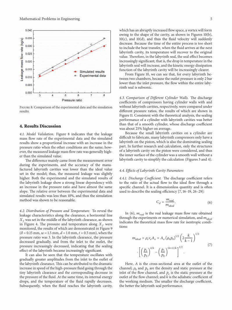

Hindawiwwwhindawicom Volume 2018
MathematicsJournal of
Hindawiwwwhindawicom Volume 2018
Mathematical Problems in Engineering
Applied MathematicsJournal of
Hindawiwwwhindawicom Volume 2018
Probability and StatisticsHindawiwwwhindawicom Volume 2018
Journal of
Hindawiwwwhindawicom Volume 2018
Mathematical PhysicsAdvances in
Complex AnalysisJournal of
Hindawiwwwhindawicom Volume 2018
OptimizationJournal of
Hindawiwwwhindawicom Volume 2018
Hindawiwwwhindawicom Volume 2018
Engineering Mathematics
International Journal of
Hindawiwwwhindawicom Volume 2018
Operations ResearchAdvances in
Journal of
Hindawiwwwhindawicom Volume 2018
Function SpacesAbstract and Applied AnalysisHindawiwwwhindawicom Volume 2018
International Journal of Mathematics and Mathematical Sciences
Hindawiwwwhindawicom Volume 2018
Hindawi Publishing Corporation httpwwwhindawicom Volume 2013Hindawiwwwhindawicom
The Scientific World Journal
Volume 2018
Hindawiwwwhindawicom Volume 2018Volume 2018
Numerical AnalysisNumerical AnalysisNumerical AnalysisNumerical AnalysisNumerical AnalysisNumerical AnalysisNumerical AnalysisNumerical AnalysisNumerical AnalysisNumerical AnalysisNumerical AnalysisNumerical AnalysisAdvances inAdvances in Discrete Dynamics in
Nature and SocietyHindawiwwwhindawicom Volume 2018
Hindawiwwwhindawicom
Dierential EquationsInternational Journal of
Volume 2018
Hindawiwwwhindawicom Volume 2018
Decision SciencesAdvances in
Hindawiwwwhindawicom Volume 2018
AnalysisInternational Journal of
Hindawiwwwhindawicom Volume 2018
Stochastic AnalysisInternational Journal of
Submit your manuscripts atwwwhindawicom