Embed Size (px)
Citation preview

1
NUMERICAL MODELLING OF DIRECT CONTACT CONDENSATION IN TRANSITION
FROM STRATIFIED TO SLUG FLOW
L. Štrubelj, I. Tiselj
Jožef Stefan Institute
Reactor Engineering Division
Jamova 39, SI-1000,
Ljubljana, Slovenia
[email protected], [email protected]
Abstract
Condensation of hot vapour on the cold liquid that is slowly flooding the horizontal pipe is numerically simulated. The experimental results were obtained from the condensation induced water hammer experiments performed on the steam-line of the PMK2 device. In most of the experimental cases, slow flooding of the pipe was abruptly interrupted by a strong slugging, where bubble of vapour is entrapped by slug. The vapour bubble rapidly condenses what is often followed by the strong water hammer induced pressure surges. The focus in the present work is on the selected experimental runs performed at higher initial pressures and temperatures, where transition from the stratified into the slug flow was not accompanied by the water hammer pressure peaks. Our computations show that the test cases without water hammer request a tough problem for CFD codes, while the prediction of condensation induced water hammer is beyond the current state of the art CFD. The basic physical model in used NEPTUNE_CFD code is 6-equation two-fluid model, with the key sub-model for the present work being the liquid heat transfer coefficient and interfacial momentum transfer model. The main parameters of the simulations compared with the experiments are liquid temperature rises in several points along the pipe. The experimental uncertainty of measured temperature is less important for comparison of simulation with experiment due to the stochastic nature of phenomena. The final liquid temperatures at the measuring points do not depend on the details of the slugging and bubble condensation, but rather on the mixing, which was caused by all the slugs that appeared in the pipe during the transient. The water heat up due to condensation gave us some information about the suitability of the applied condensation model. The Large Interface model (Coste, 2007, 2008) used in our simulations, predicts time evolution of temperatures and final temperatures on measuring points better than model based on Hughes-Duffey correlation for condensation and bubble/droplet drag force model. 1. Introduction Despite recent advances in the field of computational multifluid dynamics, only a limited analytical approach to the problem of Direct Contact Condensation (DCC) in horizontal stratified flow is possible, therefore experiments remain a necessary tool for research of the phenomena. When discussing the correlations for description of the DCC one should distinguish between the two types of the inter-phase exchange models: "integral" models, valid in the cross-section of the pipe and applicable for 1D two-fluid models, and "local" models that are required in 2D/3D models. Two frequently used "integral" correlations for heat and mass transfer during the DCC in stratified flow were derived from the experimental results by Lim et al. (1984) and Kim et al. (1985). Unlike Lim et al. (1984) and Kim et al. (1985) who performed their experiments in a pipe, Celata et al. (1986) measured DCC on slowly moving subcooled water in a "pressurizer-like" geometry and developed a special set of integral correlations for that purpose. Chan and Yuen (1990) used the experimental device of Lim et al. (1984) and analyzed influence of air on the DCC in the stratified horizontal flow. Further integral models can be found in the paper by Chun and Yu (2000b) who described their air-water and steam-water experiments in nearly horizontal stratified flow and compared various correlations for the stratified-to-slug transition with their experiments. They suggested a new model, which gives, comparing to the models of Mishima and Ishii (1980), and Taitel and Dukler (1976),

2
more accurate prediction of transition at low liquid superficial velocities. Ramamurti and Kumar (2001) performed a DCC experiment on a thick layer of moving water in the vessel with a stagnant vapour bubble and expressed the heat transfer coefficients in terms of Nusselt number as a function of liquid Reynolds and Prandtl number and the rate of sub-cooling. Hughes and Duffey (1991) introduced a "surface renewal theory" for DCC in turbulent separated flow, which points to an important role of the turbulence in the liquid layer, and developed a so-called "local" closure law for description of the inter-phase heat and mass exchange in the separated turbulent flows. Experiments and models of DCC in a rectangular duct and rectangular tank were later described by Lorencez et al. (1997) and Mikielewicz et al. (1997), respectively. Especially Lorencez et al. (1997) with their sophisticated experiment made a detailed measurement of the turbulence near the free surface and clarified the impact of the turbulence on the interfacial heat and mass transfer coefficients. 1.1. Condensation induced water hammer (CIWH) in horizontal pipes Condensation induced water hammer (CIWH) in horizontal pipes is a safety issue for various fields of engineering including nuclear (Griffith, 1996). The phenomenon starts with direct contact condensation of steam on subcooled liquid in horizontally stratified flow. Once the slug is formed due to wave reflection or surface (Kelvin-Helmholtz) instability (see fig. 1), a rapid condensation of the bubble entrapped behind the slug may follows, resulting in a strong pressure peak. Most of the CIWH studies are related with the nuclear energy; however, the phenomenon is relevant also for other fields, such as CIWH in solar thermal plants (Streicher, 2000). Chun and Yu (2000a) developed a set of prevention guidelines based on analytical approximations and their experimental research of condensation-induced water hammer. Yao et al. (1999) and He et al. (2000) presented their CIWH experiment in a horizontal pipe and 2D numerical simulations of the phenomena with a VOF model for interfacial tracking, however, their results were obtained on very coarse grids. Ansari (1999) presented his own experimental device for CIWH in horizontally stratified flow and suggested a correction to the Mishima and Ishii (1980) model for stratified-to-slug transition. Another set of experiments, with some of them being considered in the present study, with improved vapour volume fraction measurement was run at KFKI experimental device PMK2 Prasser et al. (2004a, 2004b) within the WAHALoads project of the 5th EU research program. The attempt of Gale et al. (2004) to describe the KFKI experiment with the 1D two-fluid model of the WAHA code (Tiselj et al., 2004, 1998) pointed to large uncertainties of the simulations related to the model of stratified-to-slug flow transition and correlations for interfacial heat, mass and momentum transfer.
Figure 1: Schematic view of bubble entrapment and its condensation, from left to right: the wave
appearance, the growth of the wave, the wave touches the wall and the entrapped bubble is shrinking due to condensation.
1.2. CFD and direct contact condensation (DCC) in horizontally stratified flow Various techniques for multidimensional simulations of stratified flows are described in the literature. Among the volume-discretization methods, which are considered to be relevant for the modelling of the DCC, the most important techniques for the interface tracking (IT) are: VOF method (Scardovelli and Zaleski, 1999), level-set method (Smereka, 2003), and the front-tracking method of Unverdi and Tryggvason (1992). The assumption of the sharp-interface is not always appropriate (Anderson et al., 1998) as the thickness of the interface may not be negligible comparing to the relevant scales especially near the critical temperature. Anderson et al. (1998) present a review of the models and methods that can be applied for simulations of diffuse-interfaces of finite thickness. An innovative approach by Lakehal et al. (2003) based on pseudo-spectral DNS of turbulent wavy flow at low Reynolds number is to be mentioned as a very accurate tool, but like all today's DNS studies - limited to a narrow range of flows with low Reynold number and low subcooling rates on the order of 10 K. Another option for multidimensional simulations of two-phase flows is a two-fluid model, which can be traditionally found in 1D nuclear thermal-hydraulic codes like CATHARE (Bestion, 1990) and

3
RELAP (Tiselj, Černe, 2000, Prošek, Mavko, 1999). The multidimensional two-fluid models with suitable algorithms for tracking of the "major" interfaces, might be an alternative to the pure interface tracking methods, which fail when the surface characteristic scales become comparable or smaller than the grid size; see the paper by Yadigaroglu (2005) for discussion about two-fluid and interface tracking models of two-phase flow. An example of such two-fluid model is used in CFD code CFX, which was used by Mouza et al. (2001) for simulation of the 3D wavy stratified flow without condensation. Berthelsen and Ytrehus (2005) performed 2D simulation of stratified flow in a pipe assuming steady-state turbulent flow without condensation. A further example of multidimensional two-fluid model for stratified flow can be found in a paper by Line and Lopez (1997), where the results for wavy stratified flow are shown. Simulations of stratified flow with a 2D two-fluid model were further performed by Yao et al. (2003), who made simulations of stratified flow with and without the condensation. 2D CFD simulations of ECC injection of subcooled water into horizontally stratified hot leg flow were performed by Coste (2004) using two-fluid model with interfacial heat and mass transfer model based on surface renewal concept. Boucker et al. (2004) simulated DCC with NEPTUNE_CFD (Lavieville et al., 2005) in COSI experimental device, where temperature profiles were in quite good agreement with experiment. Scheuerer et al. (2007) simulated DCC in LAKOON experimental device (Hein et al., 1995) and achieved a good agreement between the measured and calculated condensation rate. The local temperatures in simulation were underestimated. Coste (2007, 2008) introduced a method for friction and turbulence around large interfaces in simulations with two-fluid model. The large interface seen by the method is made of three layers. The thickness of each layer is one cell. The interfacial friction in this model is assumed to be the resultant of a wall-like friction in the plane parallel to the large interface and of inclusion-like drag in the perpendicular direction. The method is implemented in the NEPTUNE_CFD code and qualified on an air-water stratified flow experiment and steam/water stratified flow (COSI) experiments. The same method is used in our simulations. The goal of performed simulations is to validate the condensation and drag force model, for prediction of emergency core cooling behaviour during loss of coolant accident (LOCA) in light water nuclear power plants. There have not been many transient CFD simulations of direct contact condensation in horizontal pipes with such a large topology changes, which can also occur during LOCA. The goal is also to analyze the phenomena of stratified-to-slug flow transition and bubble entrapment in KFKI experiments. The reason for bubble entrapment (Kelvin-Helmholtz instability or reflection of wave from the end of the pipe), which cannot be recognized only from the experimental results is explained. 2. KFKI Experiments The plan of the KFKI condensation induced water hammer experiment and the experimental initial conditions are based on the recommendations of a NUREG report, prepared by Griffith (1996). For the steam bubble collapse induced water hammer, several conditions must be met in order for one to occur. These states, operations and geometries were identified in development of the experimental facility shown in fig. 2. Test section of the water hammer facility in fig. 2 consists of a 2.8 m long horizontal pipe with inner diameter 73 mm. Steam generator (SG in fig. 2) supplies vapour for the test section through the vapour inlet head which extends the horizontal test section for 0.2 m and serves as a 90 degree bend and as an inertia block (mass 200 kg). The pipe to steam generator remains open during the experiment. Liquid inlet head geometry is similar to the vapour inlet head; the distance between the centres of both inlet heads is 3.20 m. Steam-line section connected to the condenser is isolated in the water hammer experiment. The supply of cold water is obtained with a 75 litre water tank (WT in fig. 2) pressurized with nitrogen and connected to the bottom of the vertical steam-line section below the liquid inlet head. Water is injected by opening of the valve in the injection line (inner diameter 24 mm). Water hammer experiments at the PMK-2 device were performed at initial steam pressures between 10 and 40 bar and at tank liquid water temperatures between 17 and 140 °C. Cold water mass flow rates were between 0.7 and 1.7 kg/s. Before the start of each experiment the whole construction was heated with steam for a few hours. The water tank flow rate can be considered as constant during the transient.

4
WM T4 T3 T2 T1
1309 1150
575 575 588 230 335
SG
WT P1 P2 P3
3200 279 258
1007
Figure 2: Schematic view of the KFKI experimental device.
Instrumentation used in the experiment:
• Wire-mesh sensor (WM in fig. 2) measures cross-sectional distribution of vapour volume. • Four local void probes with integrated thermocouple (T1-T4 in fig. 2). • Three pressure transducers (P1-P3 in fig. 2). • Two displacement cells - strain gauges measuring axial and radial strain behind the vapour and liquid inlet heads.
2.1. Experimental results There were 35 water hammer experiments performed at PMK-2 device and described in the reports by Prasser et al. (2004a, 2004b). The most important results for the present research are actually temperature measurements, a mesh sensor vapour volume fraction measurements, and local void fraction and not the water hammer pressure peaks, since only experiments without water hammer were analyzed. There are 7 experiments without water hammer, all of them were simulated, but only the results for experiment no. 27 are presented, since conclusions for all of them are the same. It is important to stress the rather large uncertainty of the experiments - especially the maximum recorded pressure peaks: two experiments performed at very similar initial conditions can give very different pressure peaks with a difference of factor ~2 not uncommon. Repetition of the particular experiment with the same initial conditions has pointed to a rather stochastic nature of the phenomena with not very good reproducibility of the measurements. Since accurate modelling of the hot steam condensation on the cold water is an essential prerequisite for accurate water hammer simulations, the present paper focuses on the experimental cases where no water hammer appeared. In most of the experimental cases, slow flooding of the pipe was abruptly interrupted by a strong slugging and water hammer. Even the selected experimental cases without water hammer pressure peaks exhibited the onset of a minor slugging, which is again not very deterministic when one wants to predict the exact time and position where the slug bridges the pipe. During experiment cold water is slowly flooding the pipe. Some smaller slugs are formed already in the lower horizontal part. These slugs entrap bubbles, which condense and cause a significant turbulent mixing of the incoming liquid. Later the filling of the vertical pipe follows. We are interested in phenomenology in upper horizontal pipe where all measurements were performed. During the flooding of horizontal pipe surface waves and later slugs are formed due to the Kelvin-Helmholtz instability of the surface or reflection of wave at the end of the pipe. Bubble condenses and mixes the liquid water, which decreases liquid water temperature at the interface and increases the condensation mass transfer rate. The estimate of the Reynolds number shows that the flow in the liquid layer is turbulent (Re larger than ~10000) The cold water is heated up mainly due to condensation and only small part of heat up is do to structure (9-12 K average estimation).

5
3. Simulations with NEPTUNE_CFD The experiment is simulated with a CFD code NEPTUNE_CFD (Lavieville, 2005) that is developed within the framework of the NEPTUNE project, financially supported by CEA (Commissariat à l'Énergie Atomique), EDF (Électricité de France), IRSN (Institut de Radioprotection et de Sûreté Nucléaire) and AREVA-NP. It has been specifically designed for transient simulations of multiphase flows in nuclear engineering. The 6-equations model with two mass, momentum and energy balance equations is implemented in the code. The NEPTUNE_CFD is used and validated within the NURESIM project (6th framework program of EU) for simulations of critical heat flux, boiling (Končar, 2007) and pressurised thermal shock. One of the goals of the NURESIM project is to develop CFD tool with validated models for simulation of transients in nuclear power plants. The experiment was simulated also with code CFX, but we found that in simulations with CFX CPU time is longer and mass conservation is not sufficiently accurate. The computational domain shown in fig. 2 is discretized with a 3D structured grid. Initial conditions represent the pipe filled with steam at saturation temperature and boundary conditions are mass flow rate of water inlet and pressure at steam inlet. The simulations of experiment no. 27 are presented in this paper. The water mass flow rate in this experiment is 0.73 kg/s and temperature is 110 °C. The initial pressure in steamline is 30 bar and temperature is 297 °C. Our tests have shown that the whole experimental device must be simulated and not only the upper horizontal pipe (Štrubelj, 2007a), due to the significant preheating of cold water that exists already in the lower horizontal pipe. Most of the heating of liquid comes from the vapour condensation, while the heating of liquid due to the structure is small and was not simulated. 3.1. Models Simulations with NEPTUNE_CFD are performed with real gas properties (CATHARE code steam tables). More about models and numerical methods can be found in NEPTUNE_CFD documentation (Lavieville, 2005). Here only the crucial physical models for the present research are described. The k-
ε turbulence model was used for both phases. The interphase mass transfer was calculated as source per unit volume mAΓ = & , where interphase area density is A α= ∇ . Interphase mass flow rate per unit
interfacial area is calculated as:
( ),
L sat L
V sat L
HTC T Tm
h h
−=
−& (1)
where HTCL stands for liquid heat transfer coefficient, hL for liquid enthalpy, hV,sat for saturation enthalpy of vapour, TL for liquid temperature and ( )sat satT T p= for saturation temperature.
Two condensation models for heat transfer coefficient are compared. The first is calculated using surface renewal theory introduced by Hughes and Duffey (1991). This model is called Hughes-Duffey (HD) model in the present paper:
Nu tL
L
HTC L
λ
⋅= (2)
1/22Nu Re PrL t
π= (3)
where Pr is Prandtl number, NuL is Nusselt number of liquid and Ret turbulent Reynolds number of liquid. Most of the other models of condensation in stratified flow (Banerjee et al., 2004) also calculate the heat transfer coefficient as a more or less similar function of Reynolds and Prandtl
numbers: Nu Re Pra bL tConst= . Nevertheless, the turbulent Reynolds number in (3) is actually
calculated from the local parameters as:
Re t tt
L
L u
ν= (4)
where νL is liquid viscosity, Lt is length scale and ut velocity scale, which are calculated from liquid turbulence kinetic energy kL and turbulence dissipation εL:
6
1/4 1/2 ; 0.09t µ L µu C k C= = (5)
3/2L
t µL
kL C
ε=
(6)
The turbulence quantities of steam at inlet are zero. The turbulence intensity of water at inlet was taken as 5% in most of simulations although the measurements are not available. However tests with zero initial turbulence have not shown any influence on the results. The interfacial momentum transfer, usually drag closure law must also be defined in two-fluid model. The drag closure law implemented in combination with HD model is similar to bubble drag if liquid volume fraction is high and is similar to droplet drag if liquid volume fraction is low. The drag is implemented in such a way that can successfully simulate free surface flows (Lavieville, 2005). Interfacial momentum transfer model, in this paper called Large Interface (LI) model developed by Coste (2007) was also tested. The large interface seen by this method is made of three layers. The thickness of each layer is one cell. The interfacial friction in this model is assumed to be resultant of a wall-like friction in the plane parallel to the large interface and of inclusion-like drag in the perpendicular direction. In other words, it is a non-isotropic friction. A momentum exchange between the layers of model is calculated, in order to obtain results that are not dependant on the location of the interface with respect to the mesh. Turbulence is taken into account by means of a k-ε turbulent model in each phase, with a special treatment of the turbulent kinetic energy production at the large interface as presented by Coste (2007, 2008). From our experience the best results are obtained in combination of LI interfacial friction model and heat transfer coefficient model proposed by Coste (2004, 2008), where turbulent Reynolds number is calculated from turbulence quantities similar as in HD model. The heat transfer coefficient model is similar to HD model and comes from surface renewal model with renewal frequency, which is defined with Kolmogorov length scale and turbulent velocity. In all simulations with LI model this condensation model is implemented.
7/8 1/2Nu 2.7Re PrL t= (7)
Let me summarized that two sets of models were compared: • Hughes-Duffey (HD) model consists of Hughes-Duffey condensation model eq. (3) and drag
model based on bubble/droplet drag, • Large Interface (LI) model consist of 3 cell layer model for interfacial friction and
condensation model based on surface renewal model with renewal frequency, which is defined with Kolmogorov length scale and turbulent velocity eq. (7).
The simulations were performed on 2 different meshes: coarse mesh with 8 elements in pipe diameter (total of 6,465 hexa elements) and fine mesh with 16 elements in pipe diameter (total of 34,638 hexa elements). The computational time is 37 CPU-days on fine mesh. Rather small timestep must be used due to large inlet velocity of water and long time needed to fill the whole pipe system. 3.2 Results
The experiment no. 27 is simulated. The pressure measurements in this case give no usable information, since no water hammer appears in experiment. The local void measurements were not compared to simulation results, since the presence of cold liquid water or hot steam can also be observed from local temperature measurements. The local temperatures measured in experiments (the cold water temperature increase) give the only information about the mass of condensed steam and suitability of used condensation model. Nevertheless, even the local temperatures are highly affected by slug formations, the condensation of bubbles, entrapped by slugs, and mixing of liquid water. The total mass of condensed steam in experiment was calculated to be around 1.1 kg, however, this variable was not measured in the experiment. The important result of the simulations is that mass of the condensed steam does not significantly changes with mesh refinement (±2%), while the mesh refinement has larger effect on local temperature development especially in simulations with HD model. The temperature development is not the same in two experimental runs with the same conditions, since small change in any parameter changes the onset of slugging and following temperature development. In simulations, we have found that change of some parameter or even mesh

7
will result in different local temperature development. The round-off error do not have any major influence on results, more important is the mesh and the most important is the choice of physical model for condensation and momentum transfer between the phases. Volume fraction in upper horizontal steamline in simulation of experiment 27 with HD model is given in fig. 3. The Kelvin-Helmholtz instability appears at 12.25 s. The wave grows to the pipe wall and slug is formed. The bubble is entrapped by the slug at 12.3 s and at 12.45 s the bubble completely condenses. At this time the condensation mass transfer rate peak (fig. 8) is also observed. In simulations with LI model, the reason for bubble entrapment is not Kelvin-Helmholtz instability but reflection of the wave from the end of the pipe. The amplitude of the wave is increasing and finally it reaches the pipe wall. The entrapped bubble is larger then in simulations with HD model. The temperature increase is the largest far away from the vertical inlet to horizontal pipe (fig. 5), since the water is in contact with the saturated steam for longer time. Almost all the water right from the slug is at saturation temperature. The condensation rate is the largest at the end and at the beginning of the slug (fig. 6). The pressure inside the bubble is smaller than outside that is right of the slug. This pressure difference is the moving force for slug and is the largest just before bubble completely condenses. Maximum heat transfer coefficient in simulations is up to 4,000,000 W/m2K and average between 3000 to 200,000 W/m2K. Local condensation mass transfer is up to 3,500 kg/m3/s and is increasing with the mesh refinement, since the interface is smeared over smaller distance. The heat transfer coefficient is increased during the transition form the stratified into the slug flow and bubble condensation. The turbulence quantities on which heat transfer coefficient depends (turbulence kinetic energy and turbulent dissipation) are increased during the bubble condensation. Nevertheless, no water hammer was observed in experiment and in the simulations.
Figure 3: Volume fraction in upper pipe in simulations with Hughes-Duffey model at different times
(blue – water, red – steam).
Figure 4: Volume fraction in upper pipe in simulations with Large-Interface model at different times
(blue – water, red – steam).
Figure 5: Temperature in upper pipe in simulations with Large-Interface model at different times (blue
– water inlet temperature = 110 °C, red – steam saturation temperature = 234 °C).
Figure 6: Condensation mass rate in upper pipe in simulations with Large-Interface model at different
times (blue – zero, red – maximum).
8
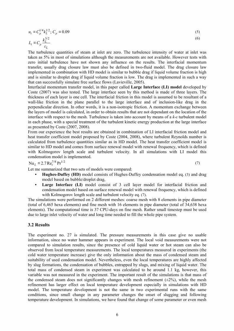
The local temperatures give us more information since they can be compared to measured ones. The local temperatures development in simulation with HD model of the experiment no. 27 on 2 different meshes and experiment at measuring point T1-T4 are plotted in fig. 7. The decrease of temperature means that the measuring point is flooded with liquid water. The temperatures in simulations do not exactly follow the experimental one and are quite different in simulations on two different meshes. In fig. 7 the measuring point T1 was first flooded with liquid water and then steam is located at measuring point and afterwards again cold water. At measuring point T1 the heat up of water in simulation is underestimated, at measuring points T2 and T3 the water heat up in simulation is comparable to the one in experiment and at measuring point T4 the water heat up in simulation is overestimated. The temperature development in simulations is not in good agreement with experimental measurements.
Figure 7: Temperature in experiment (exp) and simulations with Hughes-Duffey (HD) on two meshes
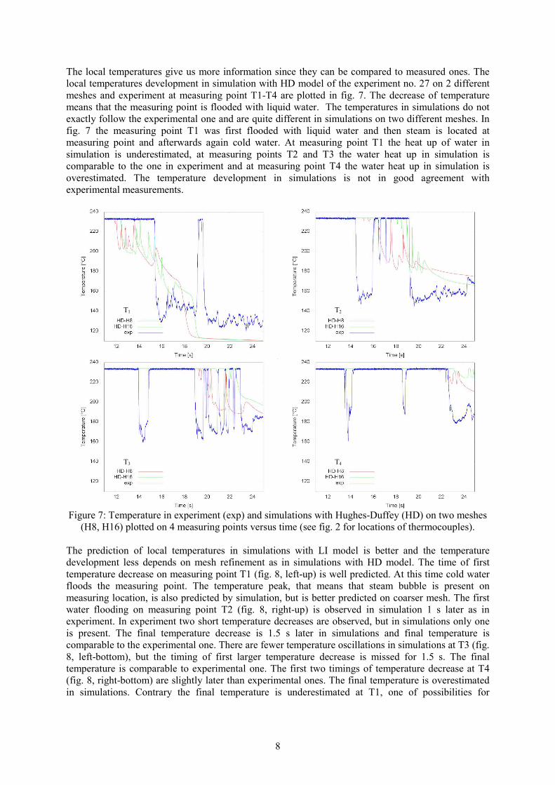
(H8, H16) plotted on 4 measuring points versus time (see fig. 2 for locations of thermocouples). The prediction of local temperatures in simulations with LI model is better and the temperature development less depends on mesh refinement as in simulations with HD model. The time of first temperature decrease on measuring point T1 (fig. 8, left-up) is well predicted. At this time cold water floods the measuring point. The temperature peak, that means that steam bubble is present on measuring location, is also predicted by simulation, but is better predicted on coarser mesh. The first water flooding on measuring point T2 (fig. 8, right-up) is observed in simulation 1 s later as in experiment. In experiment two short temperature decreases are observed, but in simulations only one is present. The final temperature decrease is 1.5 s later in simulations and final temperature is comparable to the experimental one. There are fewer temperature oscillations in simulations at T3 (fig. 8, left-bottom), but the timing of first larger temperature decrease is missed for 1.5 s. The final temperature is comparable to experimental one. The first two timings of temperature decrease at T4 (fig. 8, right-bottom) are slightly later than experimental ones. The final temperature is overestimated in simulations. Contrary the final temperature is underestimated at T1, one of possibilities for
T1 T2
T3 T4
9
underestimation at T1 could be heat capacity of the structure that was not taken into account or too small mixing in the water.
Figure 8: Temperature in experiment (exp) and simulations with Large-Interface model (LI) on two
meshes (H8, H16) plotted on 4 measuring points versus time (see fig 2 for locations of thermocouples).
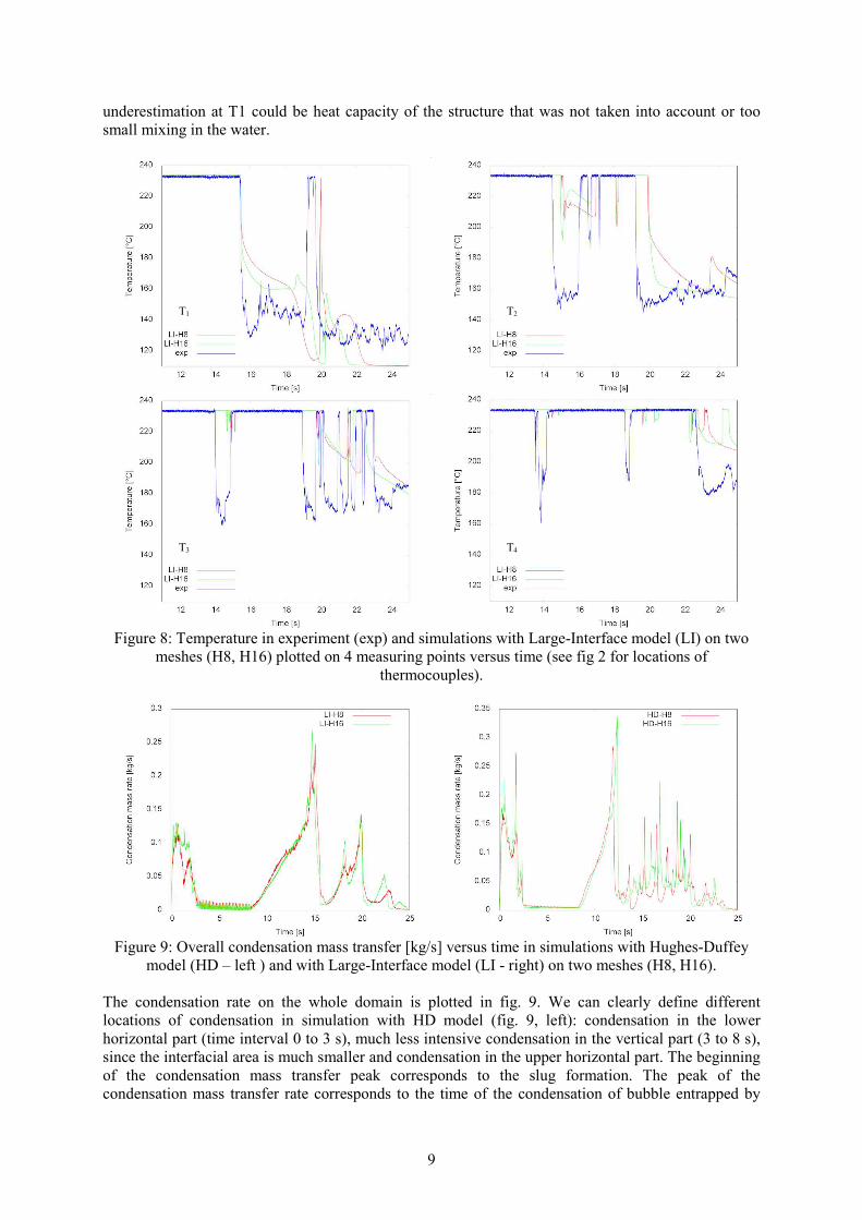
Figure 9: Overall condensation mass transfer [kg/s] versus time in simulations with Hughes-Duffey
model (HD – left ) and with Large-Interface model (LI - right) on two meshes (H8, H16).
The condensation rate on the whole domain is plotted in fig. 9. We can clearly define different locations of condensation in simulation with HD model (fig. 9, left): condensation in the lower horizontal part (time interval 0 to 3 s), much less intensive condensation in the vertical part (3 to 8 s), since the interfacial area is much smaller and condensation in the upper horizontal part. The beginning of the condensation mass transfer peak corresponds to the slug formation. The peak of the condensation mass transfer rate corresponds to the time of the condensation of bubble entrapped by
T1 T2
T3 T4
10
the slug. The peak is due to the increased heat transfer coefficient and mixing of liquid water, which decreases the liquid water temperature at the interface. The comparison with experiment is not possible since this variable was not measured. The condensation rate is nearly the same on both meshes. The peaks corresponds to bubble entrapment and condensation. 4. Conclusions Condensation of hot steam on the cold liquid that is slowly flooding the horizontal pipe, has been modelled with the computer code NEPTUNE_CFD. The experimental results were obtained from the condensation induced water hammer experiments performed on the steam-line of the PMK2 device. In most of the experimental cases, slow flooding of the pipe was abruptly interrupted by a strong slugging, which was often followed by the strong water hammer induced pressure surges. The pressure surge modelling turned out to be beyond the capabilities of the considered codes, thus the focus in the present work is on the selected experimental runs performed at higher initial pressures and temperatures, where transition from the stratified into the slug flow was not accompanied by the water hammer pressure peaks. The basic physical model in both NEPTUNE_CFD code is 6-equation two-fluid model, with the key sub-model for the present work being the liquid heat transfer coefficient and interfacial momentum transfer model. Two set of simulations were performed. The first are simulations with Hughes-Duffey (HD) model for condensation and drag model based on bubble/droplet drag. The second simulations are performed with slightly modified model for condensation and Large Interface (LI) model for interfacial momentum transfer (Coste, 2007, 2008). Turbulent quantities required by the condensation model were obtained from the k-ε turbulence model with turbulence production at interface. The main parameters of the simulations compared with the experiments were liquid temperature rises in several points along the pipe. The final liquid temperatures at the measuring points do not depend on the details of the slugging and bubble condensation, but rather on the mixing, which was caused by all the slugs that appeared in the pipe during the transient. The water heat up due to condensation gave us some information about the suitability of the applied combination of condensation model. The local temperature evolution depends on condensation model and interfacial momentum transfer model, including drag closure law and turbulence production at the interface. The local temperature evolution was much better predicted with LI model, that is why the used Large Interface model is appropriate for stratified flows with direct contact condensation. Acknowledgements
This research was financially supported by the Ministry of Higher Education, Science and Technology, Republic of Slovenia, project no. P2-0026, by young researcher project 3311-04-831075 and NURESIM project of the 6th framework program of EU.
References D.M. Anderson, G.B. McFadden, A.A. Wheeler, “Diffuse-interface methods in fluid mechanics”
Annual Review of Fluid Mechanics, 30, 139–65 (1998). M.R. Ansari, “Slug induced water-hammer in steam-water stratified two-phase flow during
condensation phenomena”, Proceedings of 3rd ASME/JSME Joint Fluids Engineering Conference, FEDSM99-6893, San Francisco, CA (1999).
I. Aya, H. Nariai, “Evaluation of heat-transfer coefficient at direct contact condensation of cold water and steam”, Nuclear Engineering and Design, 131, 17-24 (1991).
S. Banerjee, D. Lakehal, M. Fulgosi, “Surface divergence models for scalar exchange between turbulent streams”, International Journal of Multiphase Flow, 30, 963–977 (2004).
P.A. Berthelsen, T. Ytrehus, “Calculations of stratified wavy two-phase flow in pipes”, International
Journal of Multiphase flow 31, 571-592 (2005). D. Bestion, “The physical closure laws in the CATHARE code”, Nuclear Engineering and Design
124, 229-245 (1990).
11
M. Boucker, J. Lavieville, A. Martin, C. Bechaud, D. Bestion, P. Coste, “Preliminary applications of the new neptune two-phase CFD solver to pressurized thermal shock investigations”, Proceedings
of ICONE12 12th Conference on Nuclear Engineering (2004). G.P. Celata, M. Cumo, G.E. Farello, G. Focardi, “Direct contact condensation of steam on slowly
moving water”, Nuclear Engineering and Design, 96, 21-31 (1986). CFX-10 Documentation, Solver Theory, Multiphase Flow Theory, ANSYS, 2006. T.S. Chan, M.C. Yuen, “The effect of air on condensation of stratified horizontal concurrent steam
water-flow”, Journal of heat transfer, 112, 1092-1095. (1990). M.-H. Chun, S.-O. Yu, „A parametric study and a guide chart to avoid condensation-induced water
hammer in a horizontal pipe”, Nuclear Engineering and Design, 201, 239-257 (2000a). M.-H. Chun, S.-O. Yu, “Effect of steam condensation on countercurrent flow limiting in nearly
horizontal two-phase flow”, Nuclear Engineering and Design, 196, 201-217. (2000b). P. Coste, “Computational Simulation of Multi-D Liquid-Vapor Thermal Shock with Condensation”,
5th International Conference on Multiphase Flow, ICMF’04, Yokohama, Japan, May 30–June 4, (2004).
P. Coste, J. Pouvreau, J. Laviéville, M. Boucker, " A Two-phase cfd approach to the PTS problem evaluated on COSI experiment", Proceedings of the 16th International Conference on Nuclear
Engineering ICONE16, May 11-15, 2008, Orlando, Florida, USA (2008). Coste, P., et al., “Modeling Turbulence and Friction around a Large Interface in a Three- Dimension
Two- Velocity Eulerian Code”, Proc. of NURETH 12, Pittsburgh, USA (2007). J. Gale, I. Tiselj, I. Parzer, “Modelling of condensation induced water hammer”, Proc. of the 3rd
International Symposium on Two-Phase Flow Modelling and Experimentation (2004). P. Griffith, “Screening reactor steam/water piping systems for water hammer”, NUREG/CR-6519, U.S.
Nuclear Regulatory Commission (1996). F. He, J. Yang, X. Wang, “Condensation-induced steam bubble collapse in a pipeline”, Tsinghua
science and technology 5, 424-427. (2000). D. Hein, H. Ruile, J. Karl, “Kühlmittelerwärmung bei Direktkontaktkondensation an horizontalen
Schichten und vertikalen Streifen zur Quantifizierung des druckbelasteten Thermoschocks“, BMFT-Forschungsvorhaben 1500906, Abschlußbericht, Lehrstuhl für Thermische Kraftanlagen,
TU München, Germany. (1995). E. D. Hughes, R. B. Duffey, “Direct contact condensation and momentum-transfer in turbulent
separated flows”, International Journal of Multiphase flow 17, 599-619. (1991). H. J. Kim, S. C. Lee, S. G. Bankoff, “Heat transfer and interfacial drag in countercurrent steam-water
stratified flow”, International Journal of Multiphase Flow 11, 593-606. (1985). B. Končar, E. Krepper, “CFD simulation of convective flow boiling of refrigerant in a vertical
annulus”, Nucl. Eng. Des. 238, 693-706 (2008). D. Lakehal, M. Fulgosi, G. Yadigaroglu, S. Banerjee, “Direct numerical simulation of turbulent heat
transfer across a mobile, sheared gas-liquid interface”, Journal of heat transfer, 125, 1129-1139 (2003).
J. Lavieville, E. Quemerais, M. Boucker, L. Maas, “NEPTUNE CFD V1.0 User Guide” (2005) I.S. Lim, R.S. Tankin, M.C. Yuen, “Condensation measurement of horizontal cocurrent steam-water
flow”, Journal of Heat Transfer, 106, 425-432 (1984). A. Line, D. Lopez, “Two-fluid model of wavy separated two-phase flow”, International Journal of
Multiphase flow, 23, 1131-1146 (1997) C. Lorencez, Nasr-Esfahany, M. Kawaji, “Turbulence structure and prediction of interfacial heat and
mass transfer in wavy-stratified flow” AIChE Journal, 43, 1426-1435 (1997). J. Mikielewicz, M. Trela, E. Ihnatowicz, “A theoretical and experimental investigation of direct
contact condensation on a liquid layer”, Experimental Thermal and fluid Science 15, 221-227 (1997).
K. Mishima, M. Ishii, “Theoretical prediction of onset of horizontal slug flow”, Journal of Fluids
Engineering, 102, 441-445 (1980). A.A. Mouza, S.V. Paras, A.J. Karabelas, “CFD code application to wavy stratified gas-liquid flow”,
Chemical Engineering Research and Design, 79, 561-568 (2001).

12
H.M. Prasser, G. Ezsol, G. Baranyai,. “PMK-2 water hammer tests, condensation caused by cold water injection into main steam-line of VVER-440-type PWR - Quick-Look Report (QLR)”, WAHALoads project deliverable D48, (2004a).
H.M. Prasser, G. Ezsol, G. Baranyai, “PMK-2 water hammer tests, condensation caused by cold water injection into main steam-line of VVER-440-type PWR - Data Evaluation Report (DER)”, WAHALoads project deliverable D51, (2004b).
A. Prošek, B. Mavko, “Evaluating code uncertainty - I: Using the CSAU method for uncertainty analysis of a two-loop PWR SBLOCA”, Nuclear Technology, 126, 170-185 (1999).
K. Ramamurthi, S. Kumar Sunil, “Collapse of vapour locks by condensation over moving subcooled liquid”, International Journal of Heat and Mass Transfer, 44, 2983-2994 (2001).
R. Scardovelli, S. Zaleski, “Direct numerical simulation of free-surface and interfacial flow”, Annual
Review of Fluid Mechanics, 31, 567-603 (1999). M. Scheuerer, M. C. Galassi, P. Coste, F. D’Auria, “Numerical simulation of free surface flows with
heat and mass transfer”, The 12th International Topical Meeting on Nuclear Reactor Thermal
Hydraulics (NURETH-12), Pittsburg, Pennsylvania, U.S.A., September 30-October 4 (2007). P. Smereka, J. A. Sethian, “Level set methods for fluid interfaces”, Annual Review of Fluid Mechanics
35, 341-372 (2003). W. Streicher, “Minimising the risk of water hammer and other problems at the beginning of stagnation
of solar thermal plants- a theoretical approach”, Solar Energy, 69, 187-196 (2000). L. Štrubelj, I. Tiselj, “Simulation Of Kelvin-Helmholtz Instability With Cfx Code”, Proceedings of the
4th international conference on transport phenomena in multiphase systems - HEAT’2005, Gdansk, Poland (2005).
L. Štrubelj, I. Tiselj, “Heat and Mass Transfer in the Stratified Flow with ECCS Injection” International Conference Nuclear Energy for New Europe, Portorož, Slovenija, 10-13 September 2007, (2007).
L. Štrubelj, I. Tiselj, “Numerical Modelling of condensation of saturated steam on subcooled water surface in horizontally stratified flow”, The 12
th International Topical Meeting on Nuclear Reactor
Thermal Hydraulics (NURETH-12), Pittsburgh, Pennsylvania, U.S.A., September 30-October 4 (2007).
Y. Taitel, A.E. Dukler, “Model for predicting flow regime transitions in horizontal and near horizontal gas-liquid flow”, AICHE Journal, 22, 47-55 (1976).
S.A. Thorpe, “Experiments on the instability of stratified shear flows: immiscible fluids”, Journal of
Fluid Mechanics, 39, 25–48 (1969). I. Tiselj, S. Petelin, “First and second-order accurate schemes for two-fluid models”, Journal Of
Fluids Engineering, 120, 363-368 (1998). I. Tiselj, G. Černe, “Some comments on the behavior of the RELAP5 numerical scheme at very small
time steps” Nuclear Science And Engineering, 134, 306-311 (2000). I. Tiselj, G. Černe, A. Horvat, J. Gale, I. Parzer, M. Giot, J. Seynhaeve, M. Kucienska, H. Lemonnier,
“WAHA3 code manual”, WAHALoads project deliverable D10, http://www2.ijs.si/~r4www/WAHA3_manual.pdf (2004).
O. Unverdi, G. Tryggvason, “A front-tracking method for viscous, incompressible, multi-fluid flows”, Journal of Computational Physics, 100, 25-37 (1992).
G. Yadigaroglu, “Computational fluid dynamics for nuclear applications: from CFD to multi-scale CMFD”, Nuclear Engineering and Design, 235, 153-164 (2005).
W. Yao, P. Coste, D. Bestion, M. Boucker, “Two-phase pressurized thermal shock investigations using a 3D two-fluid modeling of stratified flow with condensation”, The 10
th international
Topical Meeting on Nuclear Reactor Thermal Hydraulics (NURETH-10), (2003). Z. Yao, P. Hao, X. Wang, “Condensation-induced water hammer analysis on the steam generator
accident relief system”, Transactions of the 15th International conference on structural Mechanics
in reactor technology (SMiRT-15), J03/4 (1999).