Embed Size (px)
Citation preview
HAL Id: hal-00983421https://hal-mines-paristech.archives-ouvertes.fr/hal-00983421
Submitted on 25 Apr 2014
HAL is a multi-disciplinary open accessarchive for the deposit and dissemination of sci-entific research documents, whether they are pub-lished or not. The documents may come fromteaching and research institutions in France orabroad, or from public or private research centers.
L’archive ouverte pluridisciplinaire HAL, estdestinée au dépôt et à la diffusion de documentsscientifiques de niveau recherche, publiés ou non,émanant des établissements d’enseignement et derecherche français ou étrangers, des laboratoirespublics ou privés.
Numerical modelling of hybrid arc/laser welding: acoupled approach to weld bead formation and residual
stressesOlivier Desmaison, Gildas Guillemot, Michel Bellet
To cite this version:Olivier Desmaison, Gildas Guillemot, Michel Bellet. Numerical modelling of hybrid arc/laser welding:a coupled approach to weld bead formation and residual stresses. JOM17, International Conferenceon Joining Materials, May 2013, Helsingor, Denmark. 11 p. �hal-00983421�
1
Numerical modelling of hybrid arc/laser welding: a Level Set
approach for weld bead formation and residual stresses
Olivier DESMAISON*, Gildas GUILLEMOT*, Michel BELLET* * Mines ParisTech - Centre de Mise en Forme des Matériaux (CEMEF), CNRS UMR 7635,
Rue Claude Daunesse, BP 207, 06904 Sophia-Antipolis, France [email protected], [email protected], [email protected]
ABSTRACT
The joining of high thickness steel sheets by means of hybrid Laser/GMAW welding processes is studied in
this paper. A three dimensional finite element model has been developed to simulate this process. Through an
ALE framework, a level set approach is used to model the interface between the metal and the surrounding gas.
Even though the physics of the plasma is not modelled, both thermal and material supply phenomena are taken
into account: (i) The laser and GMAW heat sources are simulated and applied on the interface through the
Continuum Surface Force method, (ii) An original method of volume element expansion has been chosen to
simulate the material supply and the bead formation. A thermo mechanical problem resolution has been settled
in this model. Depending on the thermal evolution of the mechanical parameters and on the velocity field, the
material behaviour will be elastic, elasto-visco-plastic or visco-plastic. The ALE approach enables to compute the
stresses inside the workpiece and to obtain the displacements of the workpiece borders. Two finite elements
models are presented to illustrate: (i) A hybrid arc/laser welding simulation through the thermal and material
supply resolution, (ii) A TIG welding simulation through the stress and strain mechanical resolution.
1. INTRODUCTION
The range of welding process’s use in joining operations has recently expanded thanks to the emergence of
hybrid arc / laser processes. Indeed, the coupling of a laser beam with a gas metal arc torch enhances the
efficiency of gas metal arc welding (GMAW) processes. Located ahead of the torch, this new heat source
provides additional energy to the workpiece. The resulting weld pool spreading enables to supply more material,
to mix it more homogeneously and consequently to weld better and faster.
Nevertheless, the complexity of coupled thermo-mechanical phenomena induced by this new process
increases. Therefore, a deeper understanding is required regarding the heat transfer from the heat sources and
the molten droplets to the weld pool and the heat affected zone. Actually, the neighbourhood of the fusion zone
is where deformations and stresses form first. These stresses may lead to hot tearing for some critical alloys and
highlights the need for an accurate numerical modelling.
Recent models have shown their ability to realistically simulate GMAW processes taking into account the
main thermal and fluid flow phenomena inside both the arc plasma and the weld pool [1, 2, 3]. Such heat and
fluid flow approaches have been recently applied to hybrid arc/laser melting, especially with the objective of
simulating the effect of laser, through direct or indirect modelling of keyhole phenomena [4, 5, 6, 7, 8]. As a
result, the calculated shapes of weld beads better fit the experimental ones.
Research in hybrid welding process simulations has not been yet extended to stress/strain computation. The
analysis of stress/strain formation during and after welding is generally achieved through uncoupled thermal-
mechanical calculations to, further, study hot cracking phenomena induced by the process [10, 11] or residual
stresses in the final workpiece [12, 13, 14]. In fact, while the thermal field strongly impacts the residual stress
field, the stress field affects with a low influence the thermal field.
The present paper reports on a transient three dimensional finite element model that has been developed to
simulate the weld bead forming during hybrid laser/GMAW process. The model considers both a consumable
electrode and a laser beam moving along a workpiece. However, the electrode, the arc plasma, the droplets and
the laser beam are not explicitly represented. The model includes the workpiece and a surrounding gaseous
domain for which different boundary conditions are expressed. During the formation of the weld bead, firstly,
the energy equation is solved. The material supply is taken into account thanks to the level set approach, the
interface between the surrounding gas/air and the workpiece being defined by a signed distance function. The
Proc. JOM17, Int. Conf. on Joining Materials, May 5-8, 2013, Helsingor, Denmark, International Institute of Welding (2013) 11 pages
2
resolution of Navier-Stokes equations, including first a mass source term to account for material supply, and
second surface tension forces, gives access to the velocity field, which is used to transport and update the level
set interface. The uncoupled resolution of the thermal-mechanical problem begins then. From the temperature
distribution, the mechanical properties of the 316L steel are derived. According to the material state, elasto-
visco-plastic, visco-plastic or Newtonian, the stresses and strains in the heat affected zone and in the base metal
are computed.
The paper presents first the mathematical formulation for the heat & material supply. A simulation of a
hybrid arc/laser welding process is carried out to analyse the model efficiency. A comparison between the weld
bead cut planes from simulation and experimentation is proposed. Next, the mechanical solver is detailed. A
simulation of a TIG welding process is presented. To the best of our knowledge, it is the first time that Level Set
approach and stress & strain computation are coupled. To validate the presented model a comparison between
both approaches with and without LS is carried out.
2. MATHEMATICAL FORMULATION FOR A GMAW SIMULATION
2.1. Level Set approach
A Eulerian approach is used in which the interface between the metal and the surrounding air or plasma is
defined by a level set function. This choice is justified by the modelling of multi-pass hybrid arc/laser welding
processes [16] and the objective to model arc plasma in a future extended version of the model. A nodal signed
distance function φ is defined to represent the interface between gas and metal. Because the governing mass,
energy and momentum equations are solved in the entire finite element domain, as illustrated in FIGURE 1, a
smooth interface transition of the thermal properties is needed. Near the interface a mixed property law is
defined using a sinusoidal Heaviside function H(φ) :
( ) ( )[ ]επϕπεϕϕ sin1121 ++=H for [ ]εεϕ +−∈ , (1)
The mixed law is restricted to a [-ε,+ε] domain perpendicular to the surface defined by φ(t)=0. Denoting αgas
and αmetal the values of a physical variable in both domains, the averaged or mixed value α is defined by:
( ) ( ) gasmetal HH αϕϕαα +−= ]1[ (2)
All model’s physical parameters such as the density ρ, the specific heat Cp, the thermal conductivity λ or the
viscosity η, are computed according to this mixing rule, using the same Heaviside function.
2.2. Heat transfer: energy equation
The transient energy equation solved to obtain the temperature T in the whole domain is the following:
( ) QTTvt
TCp
&rrrr =∇⋅∇−
∇⋅+∂∂ λρ
(3)
where ρ, Cp and λ are the thermal properties computed from Eq. (2). All of them are temperature dependant and
their value varies with the liquid fraction. vr
is the velocity vector. In this model the temperature
homogeneisation resulting from the fluid flow in the weld pool is only taken into account through an enhanced
liquid thermal conductivity. Nevertheless the velocity field vr
is not equal to zero (see §2.4). The study of flows in
the weld pool from the model described in this paper is detailed in [17].
Two heat sources have to be considered in a hybrid laser/arc welding simulation. The first one consists in the
heat supplied by the arc plasma for which a surface Gaussian distribution of the heat input is supposed. The
model relies on thermal radiation physics: the input heat flux qP through the surface depends on the opening
angle of the arc plasma, the distance to the electrode and the orientation of the surface normal vector with
respect to the direction of the torch. The second heat source is associated with the laser beam. In the present
model, a defocused laser beam of moderate power is supposed for which no keyhole phenomenon is observed.
3
The heat input is then modelled through a surface heat flux qL with a Gaussian distribution and an area limited to
the laser radius. Both sources - plasma and laser - are expressed through surface boundary conditions. In the
present context of level set formulation, the Continuum Surface Force developed by Brackbill et al. [18] has to be
used to transform them into volumetric heat input conditions, appearing as right hand side terms Q& in Eq. (3).
Therefore the Dirac function δ(φ) – that is the derivative of the Heaviside function H(φ) (Eq. (1), the integral of
which over [-ε,+ε] is 1) – is used to define the two volumetric heat sources: )(ϕδPP qQ =& and )(ϕδLL qQ =& .
The heat provided to the fusion zone by the impingement of molten droplets represents the last heat source
DQ& . Based on the volumetric model of Lancaster [19] and improved later by Kumar and Bhaduri [20], it consists
in defining a cylinder below the arc/plasma in the weld pool into where an additional source term is imposed.
The appropriate dimensions of the cylinder are discussed in [21]. Finally three heat source terms are added to
the right hand side of the energy equation (3):
( ) ( ) DLP QqqQ && ++= ϕδ (4)
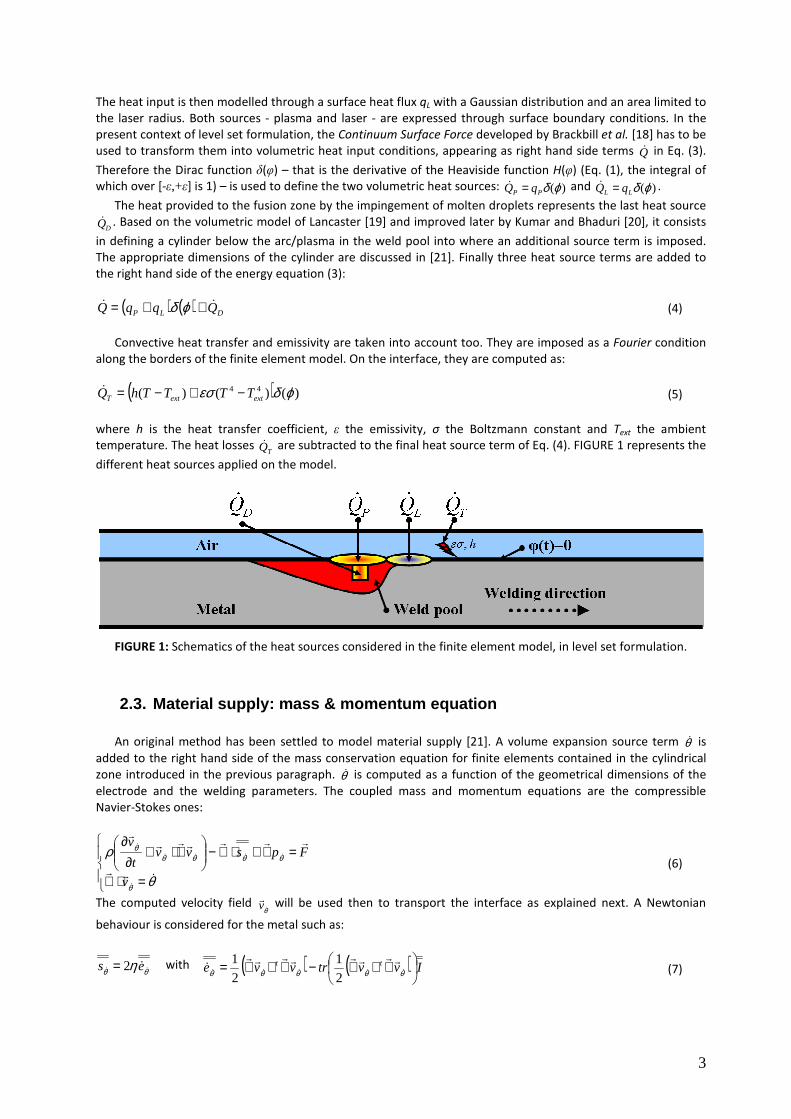
Convective heat transfer and emissivity are taken into account too. They are imposed as a Fourier condition
along the borders of the finite element model. On the interface, they are computed as:
( ) )()()( 44 ϕδεσ extextT TTTThQ −+−=& (5)
where h is the heat transfer coefficient, ε the emissivity, σ the Boltzmann constant and Text the ambient
temperature. The heat losses TQ& are subtracted to the final heat source term of Eq. (4). FIGURE 1 represents the
different heat sources applied on the model.
FIGURE 1: Schematics of the heat sources considered in the finite element model, in level set formulation.
2.3. Material supply: mass & momentum equation
An original method has been settled to model material supply [21]. A volume expansion source term θ& is
added to the right hand side of the mass conservation equation for finite elements contained in the cylindrical
zone introduced in the previous paragraph. θ& is computed as a function of the geometrical dimensions of the
electrode and the welding parameters. The coupled mass and momentum equations are the compressible
Navier-Stokes ones:
=⋅∇
=∇+⋅∇−
∇⋅+
∂∂
θ
ρ
θ
θθθθθ
&rr
rrrrrrr
&
&&&&
&
v
Fpsvvt
v
(6)
The computed velocity field θ&rv will be used then to transport the interface as explained next. A Newtonian
behaviour is considered for the metal such as:
θθ η && &es 2= with ( ) ( ) Ivvtrvve tt
∇+∇−∇+∇= θθθθθ &&&&&
rrrrrrrr&
2
1
2
1 (7)
4
where η is the viscosity and θ&&e the strain rate tensor computed from the velocity
θ&rv . As previously, the viscosity
is computed from Eq. (2) and it is temperature dependant. An enhanced value of the liquid viscosity is used for a
stronger stabilization of the mechanical resolution. The right hand side term of the momentum equation, Fr
,
includes two forces which apply onto the free surface. The first one is the gravity, gFr
. The second one is the
surface tension. First a surface force vector is defined as a function of the distance function:
nTrr
γκγ = (8)
where the mean curvature κ and the normal vector nr
are computed as:
ϕϕ ∇∇=rrr
n and nr⋅−∇=κ (9)
As this force is a surface force, once again, the Continuum Surface Force has to be applied. The final term Fr
is
equal to:
( )ϕδγTFF g
rrr+= (10)
The arc pressure is neglected in this model.
2.4. Weld bead shaping: transport & reinitialization of the Level Set
Once the velocity field associated with material supply is computed, the interface has to be transported. In
this way, the following convection equation is solved:
0=∇⋅+∂∂ ϕϕ
θ
rr&v
t (11)
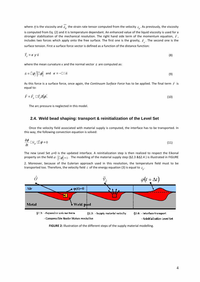
The new Level Set φ=0 is the updated interface. A reinitialization step is then realized to respect the Eikonal
property on the field φ: 1=∇ ϕr
. The modelling of the material supply step (§2.3 &§2.4 ) is illustrated in FIGURE
2. Moreover, because of the Eulerian approach used in this resolution, the temperature field must to be
transported too. Therefore, the velocity field vr
of the energy equation (3) is equal to θ&rv .
FIGURE 2: Illustration of the different steps of the supply material modelling.
5
3. HYBRID LASER/GMAW PROCESS SIMULATION
3.1. Model description
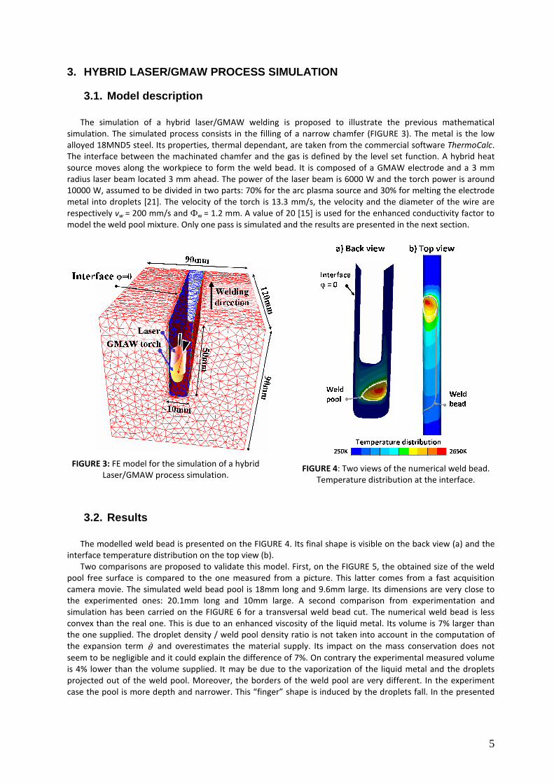
The simulation of a hybrid laser/GMAW welding is proposed to illustrate the previous mathematical
simulation. The simulated process consists in the filling of a narrow chamfer (FIGURE 3). The metal is the low
alloyed 18MND5 steel. Its properties, thermal dependant, are taken from the commercial software ThermoCalc.
The interface between the machinated chamfer and the gas is defined by the level set function. A hybrid heat
source moves along the workpiece to form the weld bead. It is composed of a GMAW electrode and a 3 mm
radius laser beam located 3 mm ahead. The power of the laser beam is 6000 W and the torch power is around
10000 W, assumed to be divided in two parts: 70% for the arc plasma source and 30% for melting the electrode
metal into droplets [21]. The velocity of the torch is 13.3 mm/s, the velocity and the diameter of the wire are
respectively vw = 200 mm/s and Фw = 1.2 mm. A value of 20 [15] is used for the enhanced conductivity factor to
model the weld pool mixture. Only one pass is simulated and the results are presented in the next section.
FIGURE 3: FE model for the simulation of a hybrid
Laser/GMAW process simulation.
FIGURE 4: Two views of the numerical weld bead.
Temperature distribution at the interface.
3.2. Results
The modelled weld bead is presented on the FIGURE 4. Its final shape is visible on the back view (a) and the
interface temperature distribution on the top view (b).
Two comparisons are proposed to validate this model. First, on the FIGURE 5, the obtained size of the weld
pool free surface is compared to the one measured from a picture. This latter comes from a fast acquisition
camera movie. The simulated weld bead pool is 18mm long and 9.6mm large. Its dimensions are very close to
the experimented ones: 20.1mm long and 10mm large. A second comparison from experimentation and
simulation has been carried on the FIGURE 6 for a transversal weld bead cut. The numerical weld bead is less
convex than the real one. This is due to an enhanced viscosity of the liquid metal. Its volume is 7% larger than
the one supplied. The droplet density / weld pool density ratio is not taken into account in the computation of
the expansion term θ& and overestimates the material supply. Its impact on the mass conservation does not
seem to be negligible and it could explain the difference of 7%. On contrary the experimental measured volume
is 4% lower than the volume supplied. It may be due to the vaporization of the liquid metal and the droplets
projected out of the weld pool. Moreover, the borders of the weld pool are very different. In the experiment
case the pool is more depth and narrower. This “finger” shape is induced by the droplets fall. In the presented
6
model, the flows inside the weld pool are not taken into account. So, the mixture of the material does not occur
which explains the curved shape of the weld pool.
Nevertheless the similarity between the simulation and the experimentation keeps very good. It proves the
efficiency of the present model. A fluid flows model could be improve the results.
FIGURE 5: Comparison of the weld pool size
between experimentation (a) and simulation (b).
FIGURE 6: Superimposition of the weld bead from
the experimentation (Exp) and the numerical
simulation (Num).
4. RESIDUAL STRESSES: BEHAVIOUR LAW & MECHANICAL EQUATION
Like all models found in the literature, this model is uncoupled. The thermal distribution field and the weld
bead shaping computations are separated from the mechanical resolution. Indeed the residual stress
computation is carried out from the final model state after energy, mass and momentum equations resolution at
each time step.
The mechanical problem to be solved is the following:
( ) ( )
+=⋅∇
=∇+⋅∇−
∇⋅+∂
∂
thelS
SSSSS
trtrv
Fpsvvt
v
εε
ρ
&&r
rrrrrrr
(12)
The solutions are the velocity of the material Svr and the pressure p. The right hand side term of the
equation, Fr
, corresponds to the body forces. Here, only the gravity force is considered. The term elε& represents
the elastic part of the strain rate tensor and the term thε& the thermal one. The deviatoric stress tensor Ss in Eq.
(12) directly derives from the velocity field Svr through the material behaviour law. As this is done at the centre
of tetrahedral elements, no mixing law is required here. Indeed, according to the state of the element (gas or
metal) and its centre temperature, the kind of resolution will not be the same. Three different behaviours are
defined in this model:
- The gas or surrounding air is considered as an incompressible fluid. Its behaviour is Newtonian (N). The
deviatoric stress tensor Ss is defined as:
es gasS &η2= (13)
where ηgas is the dynamic viscosity of the gas. Its value is very low and, as expected, stresses in the gas part of
the model are negligible. The strain rate tensor e& is computed as in Eq. (7) from the velocity Svr .
- If the metal has a temperature lower than a critical temperature TC (usually chosen as the solidus
temperature) its behaviour is elastic-visco-plastic (EVP). A multiplicative behaviour law is used in the present
model. The equivalent stress is computed as:
7
Ynm
EVPEVPK σεεσ += & (14)
where KEVP, mEVP and n are respectively the EVP consistency, the EVP strain-rate sensitivity and the hardening
coefficient. σy is the yield stress. These four material parameters are temperature dependant. The equivalent
strain ε is an input from the previous time step whereas the equivalent strain rate ε& depends on the velocity
Svr .
- If the metal has a temperature higher than the critical temperature TC, its behaviour is visco-plastic (VP). The
Norton-Hoff law is applied to express the deviatoric stress tensor:
( ) ( )eKs VPm
PVPS &&15.0
32−= ε (15)
where KVP, mVP are respectively the VP consistency and the VP strain-rate sensitivity which are temperature
dependant.
Moreover, the temperature influence on the residual stress computation is also taken into account through
the mass conservation equation of Eq. (12). Indeed, the thermal part of the strain rate tensor thε& depends on the
thermal evolution of the density:
( ) ( )( )
( )( )t
T
Tt
T
T
T
TTtr th
∂∂−=
∂∂
∂∂−== ρ
ρρ
ραε 1
3
133 && (16)
This mechanical problem is non linear due to the velocity dependence of the behaviour law. So a Newton-
Raphson method has to be used. After convergence, the iterative resolution provides the nodal velocity and
pressure fields Svr and p. From the velocity field
Svr and the mechanical time step ∆tM the nodal displacements
are computed:
MSttt tvxx ∆+=∆+ r
(17)
Whereas in the material supply resolution a Eulerian approach is used (the velocity field θ&rv is used to transport
the interface and the temperature), in this part, a Lagrangian approach is considered. In fact, the mesh is
convected by the velocity field Svr . So the impact of the mechanical resolution on the level set function and the
interface is also taken into account.
5. RESIDUAL STRESSES COMPUTATION IN TIG WELDING
5.1. Model description
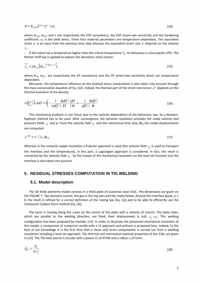
The 3D finite elements model consists in a thick plate of austenitic steel 316L. The dimensions are given on
the FIGURE 7. Two domains coexist: the gas in the top part and the metal below. Around the interface plane, φ =
0, the mesh is refined for a correct definition of the mixing law (Eq. (1)) and to be able to efficiently use the
Continuum Surface Force method (Eq. (4)).
The torch is moving along the x-axis on the centre of the plate with a velocity of 1mm/s. The plate sides,
which are parallel to the welding direction, are fixed: their displacement is null, 0=Svr . This welding
configuration has been proposed by Hamide, [15]. In order to illustrate the presented mechanical resolution of
this model, a comparison of numerical results with a LS approach and without is proposed here. Indeed, to the
best of our knowledge it is the first time that a stress and strain computation is carried out from a welding
simulation including a level set approach. The thermal and mechanical material properties of the 316L are given
in [15]. The TIG heat source is circular with a power PP of 975W and a radius rP of 5mm:
2p
PP
r
PQ
π=&
(18)
8
FIGURE 7: Model description.
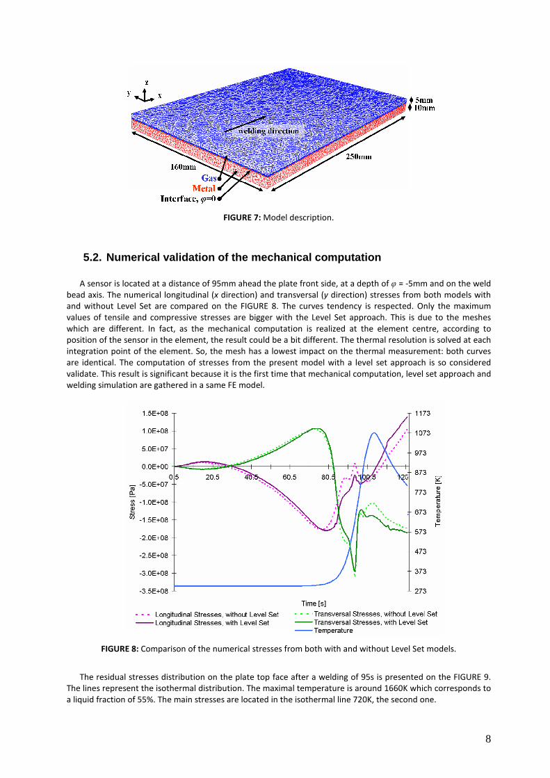
5.2. Numerical validation of the mechanical computation
A sensor is located at a distance of 95mm ahead the plate front side, at a depth of φ = -5mm and on the weld
bead axis. The numerical longitudinal (x direction) and transversal (y direction) stresses from both models with
and without Level Set are compared on the FIGURE 8. The curves tendency is respected. Only the maximum
values of tensile and compressive stresses are bigger with the Level Set approach. This is due to the meshes
which are different. In fact, as the mechanical computation is realized at the element centre, according to
position of the sensor in the element, the result could be a bit different. The thermal resolution is solved at each
integration point of the element. So, the mesh has a lowest impact on the thermal measurement: both curves
are identical. The computation of stresses from the present model with a level set approach is so considered
validate. This result is significant because it is the first time that mechanical computation, level set approach and
welding simulation are gathered in a same FE model.
FIGURE 8: Comparison of the numerical stresses from both with and without Level Set models.
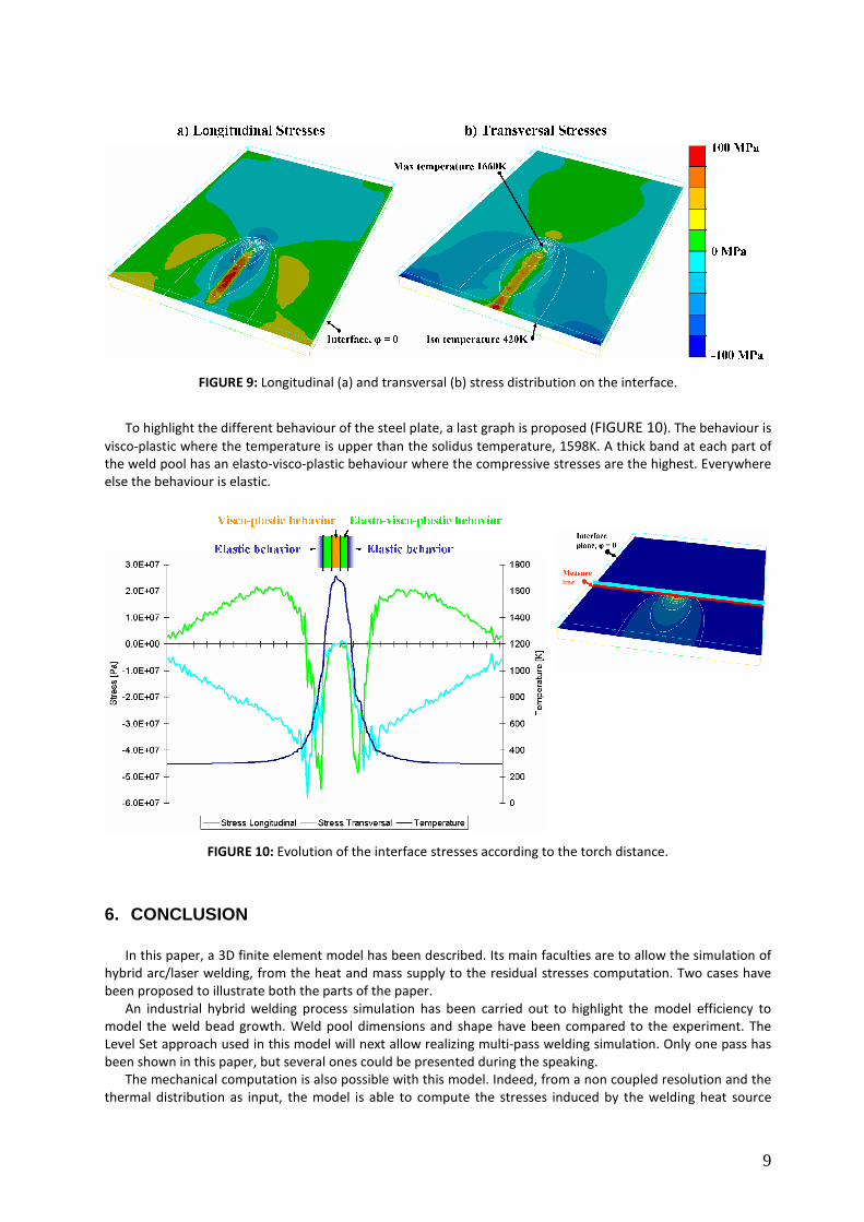
The residual stresses distribution on the plate top face after a welding of 95s is presented on the FIGURE 9.
The lines represent the isothermal distribution. The maximal temperature is around 1660K which corresponds to
a liquid fraction of 55%. The main stresses are located in the isothermal line 720K, the second one.
9
FIGURE 9: Longitudinal (a) and transversal (b) stress distribution on the interface.
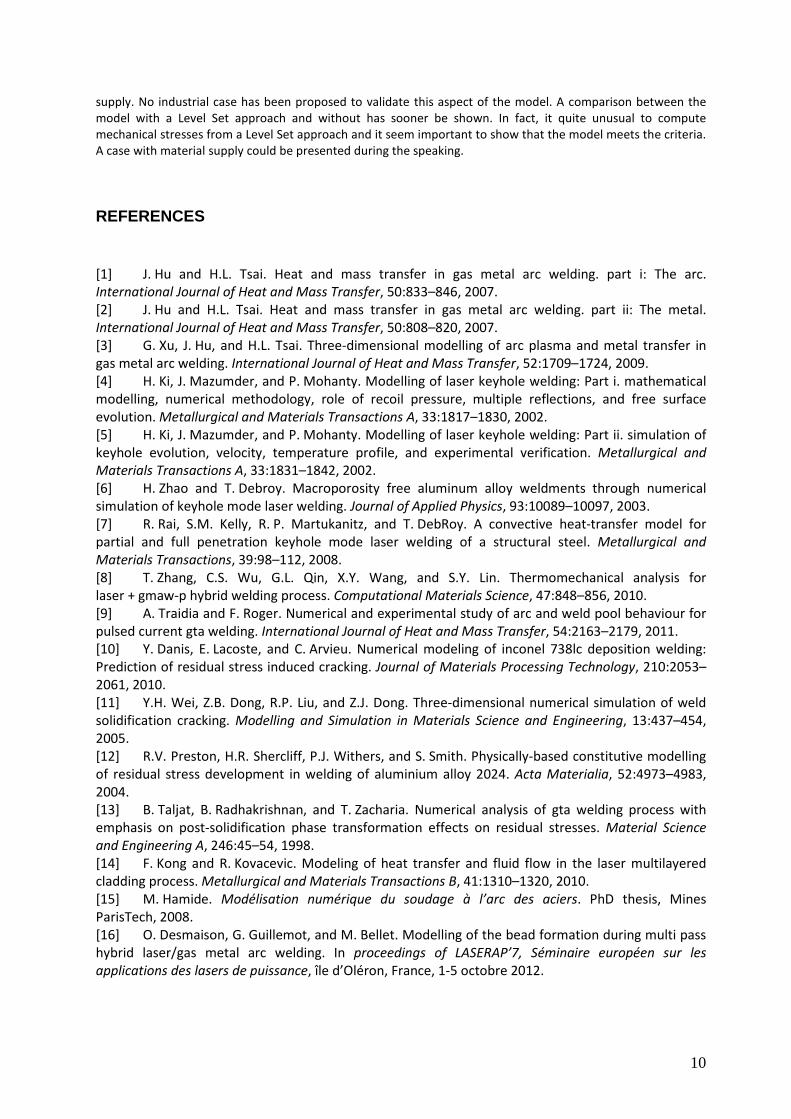
To highlight the different behaviour of the steel plate, a last graph is proposed (FIGURE 10). The behaviour is
visco-plastic where the temperature is upper than the solidus temperature, 1598K. A thick band at each part of
the weld pool has an elasto-visco-plastic behaviour where the compressive stresses are the highest. Everywhere
else the behaviour is elastic.
FIGURE 10: Evolution of the interface stresses according to the torch distance.
6. CONCLUSION
In this paper, a 3D finite element model has been described. Its main faculties are to allow the simulation of
hybrid arc/laser welding, from the heat and mass supply to the residual stresses computation. Two cases have
been proposed to illustrate both the parts of the paper.
An industrial hybrid welding process simulation has been carried out to highlight the model efficiency to
model the weld bead growth. Weld pool dimensions and shape have been compared to the experiment. The
Level Set approach used in this model will next allow realizing multi-pass welding simulation. Only one pass has
been shown in this paper, but several ones could be presented during the speaking.
The mechanical computation is also possible with this model. Indeed, from a non coupled resolution and the
thermal distribution as input, the model is able to compute the stresses induced by the welding heat source
10
supply. No industrial case has been proposed to validate this aspect of the model. A comparison between the
model with a Level Set approach and without has sooner be shown. In fact, it quite unusual to compute
mechanical stresses from a Level Set approach and it seem important to show that the model meets the criteria.
A case with material supply could be presented during the speaking.
REFERENCES
[1] J. Hu and H.L. Tsai. Heat and mass transfer in gas metal arc welding. part i: The arc.
International Journal of Heat and Mass Transfer, 50:833–846, 2007.
[2] J. Hu and H.L. Tsai. Heat and mass transfer in gas metal arc welding. part ii: The metal.
International Journal of Heat and Mass Transfer, 50:808–820, 2007.
[3] G. Xu, J. Hu, and H.L. Tsai. Three-dimensional modelling of arc plasma and metal transfer in
gas metal arc welding. International Journal of Heat and Mass Transfer, 52:1709–1724, 2009.
[4] H. Ki, J. Mazumder, and P. Mohanty. Modelling of laser keyhole welding: Part i. mathematical
modelling, numerical methodology, role of recoil pressure, multiple reflections, and free surface
evolution. Metallurgical and Materials Transactions A, 33:1817–1830, 2002.
[5] H. Ki, J. Mazumder, and P. Mohanty. Modelling of laser keyhole welding: Part ii. simulation of
keyhole evolution, velocity, temperature profile, and experimental verification. Metallurgical and
Materials Transactions A, 33:1831–1842, 2002.
[6] H. Zhao and T. Debroy. Macroporosity free aluminum alloy weldments through numerical
simulation of keyhole mode laser welding. Journal of Applied Physics, 93:10089–10097, 2003.
[7] R. Rai, S.M. Kelly, R. P. Martukanitz, and T. DebRoy. A convective heat-transfer model for
partial and full penetration keyhole mode laser welding of a structural steel. Metallurgical and
Materials Transactions, 39:98–112, 2008.
[8] T. Zhang, C.S. Wu, G.L. Qin, X.Y. Wang, and S.Y. Lin. Thermomechanical analysis for
laser + gmaw-p hybrid welding process. Computational Materials Science, 47:848–856, 2010.
[9] A. Traidia and F. Roger. Numerical and experimental study of arc and weld pool behaviour for
pulsed current gta welding. International Journal of Heat and Mass Transfer, 54:2163–2179, 2011.
[10] Y. Danis, E. Lacoste, and C. Arvieu. Numerical modeling of inconel 738lc deposition welding:
Prediction of residual stress induced cracking. Journal of Materials Processing Technology, 210:2053–
2061, 2010.
[11] Y.H. Wei, Z.B. Dong, R.P. Liu, and Z.J. Dong. Three-dimensional numerical simulation of weld
solidification cracking. Modelling and Simulation in Materials Science and Engineering, 13:437–454,
2005.
[12] R.V. Preston, H.R. Shercliff, P.J. Withers, and S. Smith. Physically-based constitutive modelling
of residual stress development in welding of aluminium alloy 2024. Acta Materialia, 52:4973–4983,
2004.
[13] B. Taljat, B. Radhakrishnan, and T. Zacharia. Numerical analysis of gta welding process with
emphasis on post-solidification phase transformation effects on residual stresses. Material Science
and Engineering A, 246:45–54, 1998.
[14] F. Kong and R. Kovacevic. Modeling of heat transfer and fluid flow in the laser multilayered
cladding process. Metallurgical and Materials Transactions B, 41:1310–1320, 2010.
[15] M. Hamide. Modélisation numérique du soudage à l’arc des aciers. PhD thesis, Mines
ParisTech, 2008.
[16] O. Desmaison, G. Guillemot, and M. Bellet. Modelling of the bead formation during multi pass
hybrid laser/gas metal arc welding. In proceedings of LASERAP’7, Séminaire européen sur les
applications des lasers de puissance, île d’Oléron, France, 1-5 octobre 2012.
11
[17] O. Desmaison, G. Guillemot, and M. Bellet. A multi-physics level set approach for the
simulation of the hybrid laser / gmaw process. In proceedings of IWS conference, 10th Int. Seminar on
Numerical Analysis of Weldability, Seggau, Austria, 24 - 26 September 2012.
[18] J.U. Brackbill, D.B. Kothe, and C. Zemach. A continuum method for modelling surface tension.
Journal of Computational Physics, 100:335–354, 1991.
[19] J.F. Lancaster. The physics of welding. Physics in technology, 15, 1984.
[20] S. Kumar and S.C. Bhaduri. Three-dimensional finite element modelling of gas metal-arc
welding. Metallurgical Transactions B, 25:435–441, 1994.
[21] M. Bellet and M. Hamide. Direct modelling of material deposit and identification of energy
transfer in gas metal arc welding. International Journal of Numerical Methods for Heat & Fluid Flow,
Accepted, 2012.


![Journal of American Science 0203arc welding, atomic hydrogen welding, shielded metal arc welding, plasma arc welding, electroslag welding, etc. Arc welding has been described [3] to](https://img.pdfslide.net/doc/110x75/5ec0a6e76045b75960496969/journal-of-american-science-arc-welding-atomic-hydrogen-welding-shielded-metal.jpg)