Embed Size (px)
Citation preview
8th European LS-DYNA Users Conference, Strasbourg – Ma y 2011
1
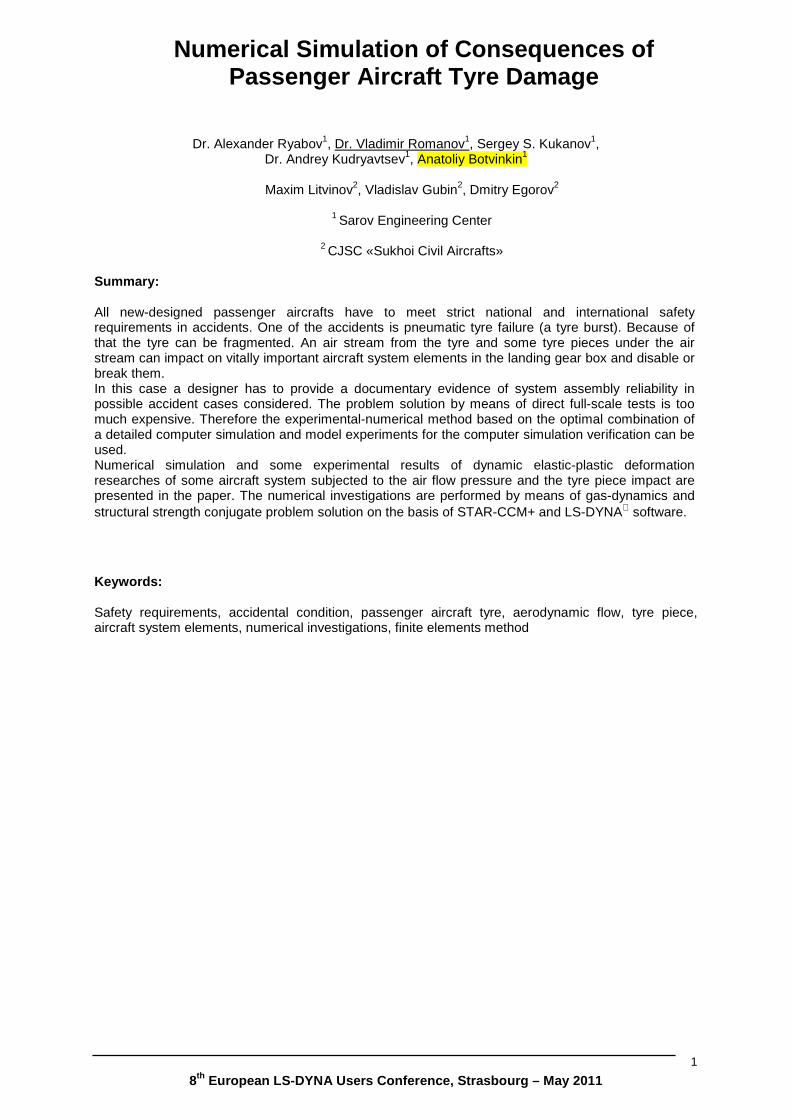
Numerical Simulation of Consequences of Passenger Aircraft Tyre Damage
Dr. Alexander Ryabov1, Dr. Vladimir Romanov1, Sergey S. Kukanov1, Dr. Andrey Kudryavtsev1, Anatoliy Botvinkin1
Maxim Litvinov2, Vladislav Gubin2, Dmitry Egorov2
1 Sarov Engineering Center
2 CJSC «Sukhoi Civil Aircrafts»
Summary: All new-designed passenger aircrafts have to meet strict national and international safety requirements in accidents. One of the accidents is pneumatic tyre failure (a tyre burst). Because of that the tyre can be fragmented. An air stream from the tyre and some tyre pieces under the air stream can impact on vitally important aircraft system elements in the landing gear box and disable or break them. In this case a designer has to provide a documentary evidence of system assembly reliability in possible accident cases considered. The problem solution by means of direct full-scale tests is too much expensive. Therefore the experimental-numerical method based on the optimal combination of a detailed computer simulation and model experiments for the computer simulation verification can be used. Numerical simulation and some experimental results of dynamic elastic-plastic deformation researches of some aircraft system subjected to the air flow pressure and the tyre piece impact are presented in the paper. The numerical investigations are performed by means of gas-dynamics and structural strength conjugate problem solution on the basis of STAR-CCM+ and LS-DYNA software.
Keywords: Safety requirements, accidental condition, passenger aircraft tyre, aerodynamic flow, tyre piece, aircraft system elements, numerical investigations, finite elements method
8th European LS-DYNA Users Conference, Strasbourg – Ma y 2011
2
1. Introduction
New requirements were added into the national and international aircraft safety rules [1-5] after the tragedy accident with Concord when more than 100 people died. Russian National Safety Rules for civil aircraft include item corresponding to the 25.729(f) AP-25\SC-25\FAR-25 requirement:
Equipment needed for safe exploitation of an aircraft and installed on a landing gear and handling in gear compartments must be protected against damage resulting from:
• Tyre explosion (ref. АМС 25.729(f))
• Tread detachment.
Damage effects are defined according to the CRI (Wheel & Tyre Model) D-05 (17 Jan 2007):
• Impact of the air stream from the tyre exploded.
• Impact of the tyre piece.
A design analysis of the new Russian passenger aircraft Sukhoi Superjet-100 showed that in spite of complexity of the construction and the amount of details and elements inside the landing gear compartment, sensitive to the air jet or tyre piece impact, are thin plates and thin-wall pipes. Therefore to verify accuracy of the numerical methodology it was decided to carry out some experiments to investigate dynamic elastic-plastic deformation of the typical details as a result of the air jet or tread piece impact.
2. Statement of the model
There are two problems under consideration: gas flow impact on the plate and tyre piece impact on the pipe.
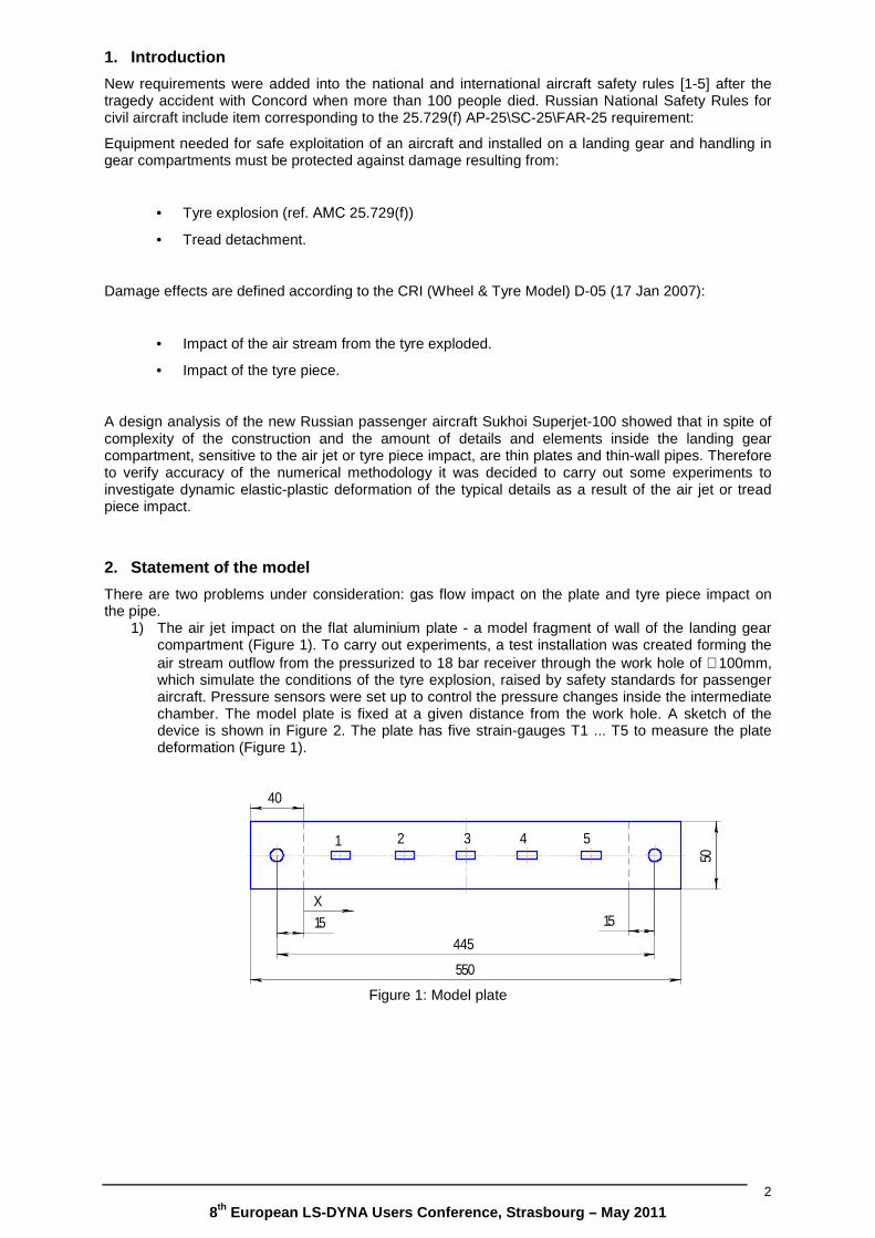
1) The air jet impact on the flat aluminium plate - a model fragment of wall of the landing gear compartment (Figure 1). To carry out experiments, a test installation was created forming the air stream outflow from the pressurized to 18 bar receiver through the work hole of ∅100mm, which simulate the conditions of the tyre explosion, raised by safety standards for passenger aircraft. Pressure sensors were set up to control the pressure changes inside the intermediate chamber. The model plate is fixed at a given distance from the work hole. A sketch of the device is shown in Figure 2. The plate has five strain-gauges T1 ... T5 to measure the plate deformation (Figure 1).
1 2 3 4 5
550
44515
40
15
50
X
1 2 3 4 5
550
15
40
15
50
X
Figure 1: Model plate
8th European LS-DYNA Users Conference, Strasbourg – Ma y 2011
3
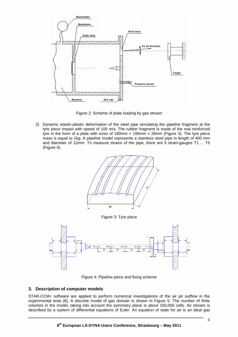
Figure 2: Scheme of plate loading by gas stream
2) Dynamic elastic-plastic deformation of the steel pipe simulating the pipeline fragment at the
tyre piece impact with speed of 100 m/s. The rubber fragment is made of the real reinforced tyre in the form of a plate with sizes of 180mm × 190mm × 26mm (Figure 3). The tyre piece mass is equal to 1kg. A pipeline model represents a stainless steel pipe in length of 400 mm and diameter of 12mm. To measure strains of the pipe, there are 5 strain-gauges T1 ... T5 (Figure 4).
Figure 3: Tyre piece
Figure 4: Pipeline piece and fixing scheme
3. Description of computer models
STAR-CCM+ software are applied to perform numerical investigations of the air jet outflow in the experimental tests [6]. A discrete model of gas domain is shown in Figure 5. The number of finite volumes in the model, taking into account the symmetry plane is about 150,000 cells. Air stream is described by a system of differential equations of Euler. An equation of state for air is an ideal gas
8th European LS-DYNA Users Conference, Strasbourg – Ma y 2011
4
model. The explicit method was used for numerical solution of the system of gas dynamic equations, integration time-step is automatically selected.
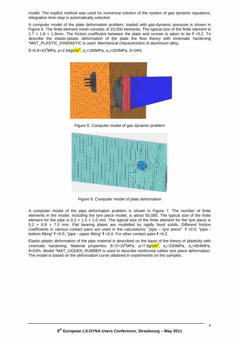
A computer model of the plate deformation problem, loaded with gas-dynamic pressure is shown in Figure 6. The finite-element mesh consists of 23,000 elements. The typical size of the finite element is 1.7 × 1.8 × 1.9mm. The friction coefficient between the plate and screws is taken to be f =0.2. To describe the elastic-plastic deformation of the plate the flow theory with kinematic hardening *MAT_PLASTIC_KINEMATIC is used. Mechanical characteristics of aluminium alloy:
Е=6.8×10⁴МPа, ρ=2.64g/cm3, σy=160MPa, σu=320MPa, δ=24%.
Figure 5: Computer model of gas dynamic problem
Figure 6: Computer model of plate deformation
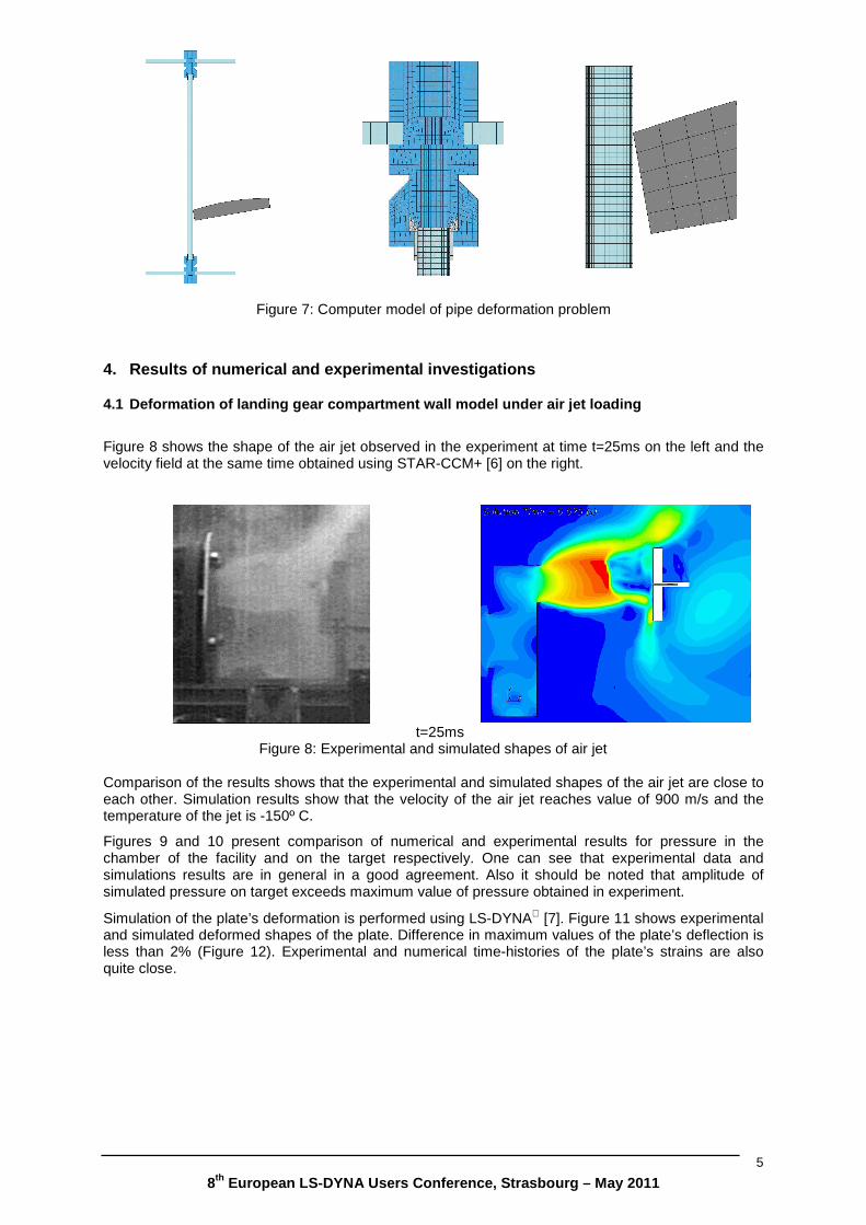
A computer model of the pipe deformation problem is shown in Figure 7. The number of finite elements in the model, including the tyre piece model, is about 50,000. The typical size of the finite element for the pipe is 0.2 × 1.0 × 1.0 mm. The typical size of the finite element for the tyre piece is 5.2 × 6.8 × 7.0 mm. Flat bearing plates are modelled by rigidly fixed solids. Different friction coefficients in various contact pairs are used in the calculations: "pipe – tyre piece" f =0.5; "pipe - bottom fitting" f =0.5; "pipe - upper fitting" f =0.0. For other contact pairs f =0.2.
Elastic-plastic deformation of the pipe material is described on the basis of the theory of plasticity with cinematic hardening. Material properties: Е=2×10⁵MPа, ρ=7.9g/cm3, σy=230MPа, σu=654MPа, δ=53%. Model *MAT_OGDEN_RUBBER is used to describe reinforced rubber tyre piece deformation. The model is based on the deformation curve obtained in experiments on the samples.
8th European LS-DYNA Users Conference, Strasbourg – Ma y 2011
5
Figure 7: Computer model of pipe deformation problem
4. Results of numerical and experimental investigat ions
4.1 Deformation of landing gear compartment wall mo del under air jet loading
Figure 8 shows the shape of the air jet observed in the experiment at time t=25ms on the left and the velocity field at the same time obtained using STAR-CCM+ [6] on the right.
t=25ms
Figure 8: Experimental and simulated shapes of air jet
Comparison of the results shows that the experimental and simulated shapes of the air jet are close to each other. Simulation results show that the velocity of the air jet reaches value of 900 m/s and the temperature of the jet is -150º C.
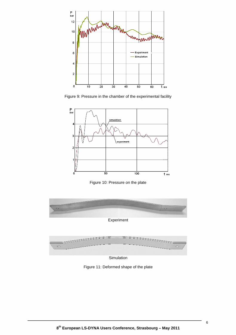
Figures 9 and 10 present comparison of numerical and experimental results for pressure in the chamber of the facility and on the target respectively. One can see that experimental data and simulations results are in general in a good agreement. Also it should be noted that amplitude of simulated pressure on target exceeds maximum value of pressure obtained in experiment.
Simulation of the plate’s deformation is performed using LS-DYNA [7]. Figure 11 shows experimental and simulated deformed shapes of the plate. Difference in maximum values of the plate’s deflection is less than 2% (Figure 12). Experimental and numerical time-histories of the plate’s strains are also quite close.
8th European LS-DYNA Users Conference, Strasbourg – Ma y 2011
6
Figure 9: Pressure in the chamber of the experimental facility
Figure 10: Pressure on the plate
Experiment
Simulation
Figure 11: Deformed shape of the plate
8th European LS-DYNA Users Conference, Strasbourg – Ma y 2011
7
Figure 12: The plate’s residual deflection
Sensor T2 Sensor T3
Figure 13: Strains in the plate
4.2 Deformation of the pipeline model at the tyre p iece impact
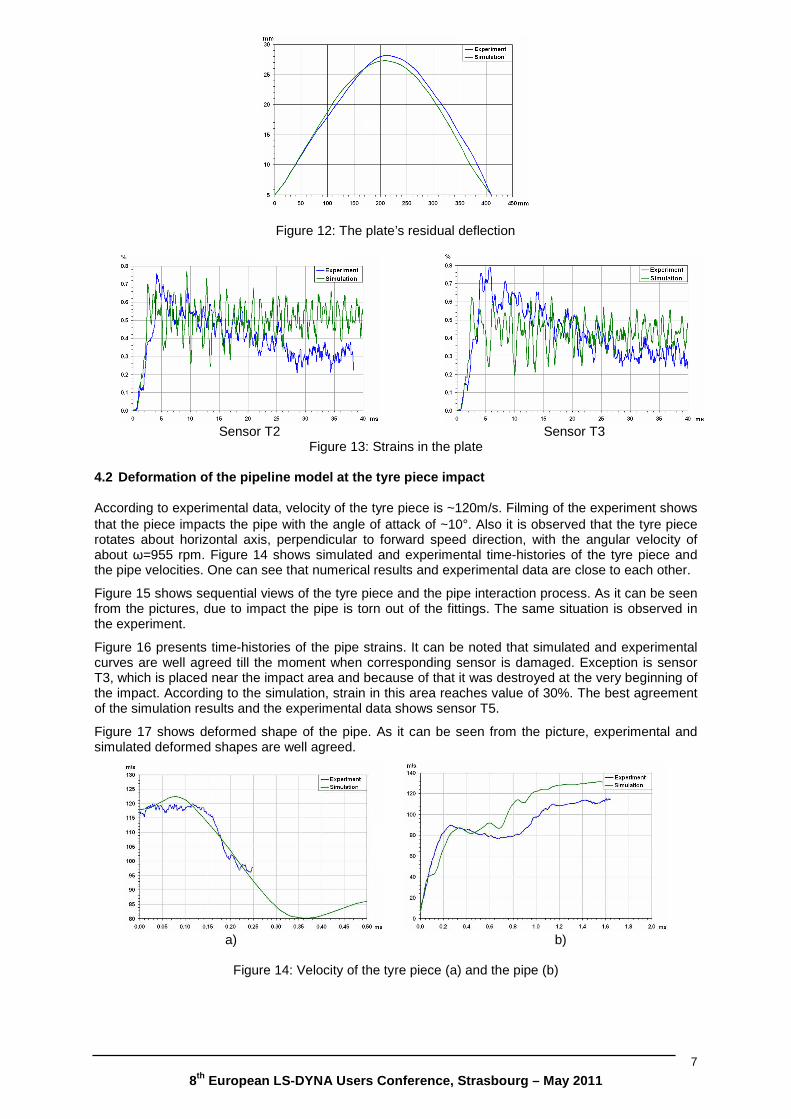
According to experimental data, velocity of the tyre piece is ~120m/s. Filming of the experiment shows that the piece impacts the pipe with the angle of attack of ~10°. Also it is observed that the tyre piece rotates about horizontal axis, perpendicular to forward speed direction, with the angular velocity of about ω=955 rpm. Figure 14 shows simulated and experimental time-histories of the tyre piece and the pipe velocities. One can see that numerical results and experimental data are close to each other.
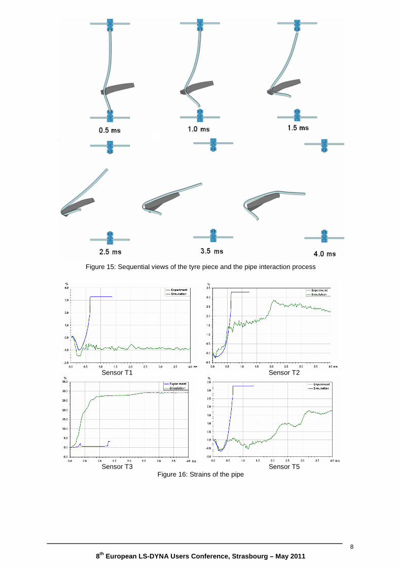
Figure 15 shows sequential views of the tyre piece and the pipe interaction process. As it can be seen from the pictures, due to impact the pipe is torn out of the fittings. The same situation is observed in the experiment.
Figure 16 presents time-histories of the pipe strains. It can be noted that simulated and experimental curves are well agreed till the moment when corresponding sensor is damaged. Exception is sensor T3, which is placed near the impact area and because of that it was destroyed at the very beginning of the impact. According to the simulation, strain in this area reaches value of 30%. The best agreement of the simulation results and the experimental data shows sensor T5.
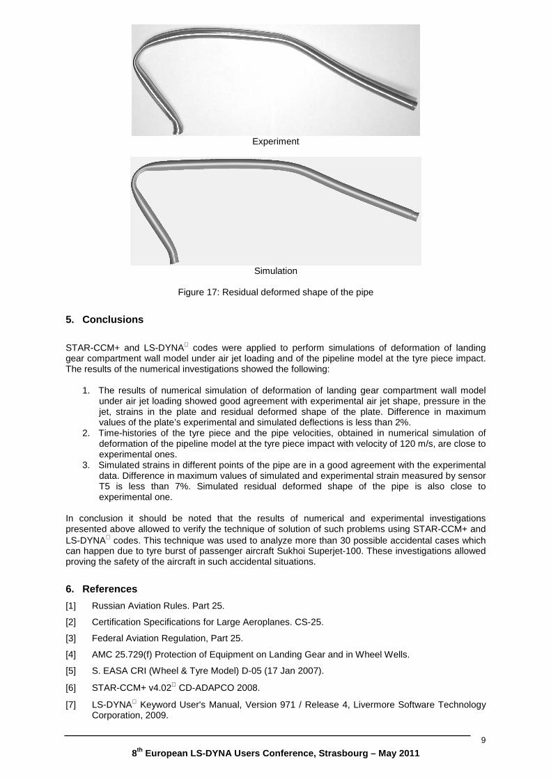
Figure 17 shows deformed shape of the pipe. As it can be seen from the picture, experimental and simulated deformed shapes are well agreed.
a) b)
Figure 14: Velocity of the tyre piece (a) and the pipe (b)
8th European LS-DYNA Users Conference, Strasbourg – Ma y 2011
8
Figure 15: Sequential views of the tyre piece and the pipe interaction process
Sensor T1 Sensor T2
Sensor T3 Sensor T5
Figure 16: Strains of the pipe
8th European LS-DYNA Users Conference, Strasbourg – Ma y 2011
9
Experiment
Simulation
Figure 17: Residual deformed shape of the pipe
5. Conclusions
STAR-CCM+ and LS-DYNA codes were applied to perform simulations of deformation of landing gear compartment wall model under air jet loading and of the pipeline model at the tyre piece impact. The results of the numerical investigations showed the following:
1. The results of numerical simulation of deformation of landing gear compartment wall model under air jet loading showed good agreement with experimental air jet shape, pressure in the jet, strains in the plate and residual deformed shape of the plate. Difference in maximum values of the plate’s experimental and simulated deflections is less than 2%.
2. Time-histories of the tyre piece and the pipe velocities, obtained in numerical simulation of deformation of the pipeline model at the tyre piece impact with velocity of 120 m/s, are close to experimental ones.
3. Simulated strains in different points of the pipe are in a good agreement with the experimental data. Difference in maximum values of simulated and experimental strain measured by sensor T5 is less than 7%. Simulated residual deformed shape of the pipe is also close to experimental one.
In conclusion it should be noted that the results of numerical and experimental investigations presented above allowed to verify the technique of solution of such problems using STAR-CCM+ and LS-DYNA codes. This technique was used to analyze more than 30 possible accidental cases which can happen due to tyre burst of passenger aircraft Sukhoi Superjet-100. These investigations allowed proving the safety of the aircraft in such accidental situations.
6. References
[1] Russian Aviation Rules. Part 25.
[2] Certification Specifications for Large Aeroplanes. CS-25.
[3] Federal Aviation Regulation, Part 25.
[4] AMC 25.729(f) Protection of Equipment on Landing Gear and in Wheel Wells.
[5] S. EASA CRI (Wheel & Tyre Model) D-05 (17 Jan 2007).
[6] STAR-CCM+ v4.02 CD-ADAPCO 2008.
[7] LS-DYNA Keyword User's Manual, Version 971 / Release 4, Livermore Software Technology Corporation, 2009.