Embed Size (px)
Citation preview

Instructions for use
Title Numerical Simulation of Gas-Liquid Two-Phase Flow in a Horizontally Placed Hydrophobic Rectangular Channel (Part1, Influence of Abrupt Expansion)
Author(s) Ueda, Y.; Nakajima, T.; Ishii, T.; Tsujino, R.; Iguchi, M.
Citation High Temperature Materials and Processes, 31(4-5): 405-410
Issue Date 2012-10
Doc URL http://hdl.handle.net/2115/53558
Rights The final publication is available at www.degruyter.com
Type article
File Information HTMP31-4-5_405-410.pdf
Hokkaido University Collection of Scholarly and Academic Papers : HUSCAP

DOI 10.1515/htmp-2012-0074 High Temp. Mater. Proc. 2012; 31(4-5): 405–410
Y. Ueda*, T. Nakajima, T. Ishii, R. Tsujino and M. Iguchi
Numerical Simulation of Gas-Liquid Two-Phase Flow in a Horizontally Placed Hydrophobic Rectangular Channel (Part 1, Influence of Abrupt Expansion)
Abstract: This paper aims to computationally investigate flow patterns of gasliquid twophase with an abrupt expansion. To do so, the present computation is nicely verified against the previous experimental results for a good wettability surface. These rectangular channels have a thickness narrower than the Laplace constant of the present situation. Under a poor wettability condition, this narrow thickness affects the flow pattern; e.g., the air phase forms channeling behind the expansion in a low airflow rate whereas the air phase becomes fragments of bubbles due to the expansion under a good wettability condition.
Keywords: twophase flow, rectangular channel, wettability, abrupt expansion, CFD
PACS® (2010). 47.15.x, 47.55.t, 68.08.Bc
*Corresponding author: Y. Ueda: Division of Materials Science and Engineering, Graduate School of Engineering, Hokkaido University, Nishi 8, Kita 13, Kita-Ku, Sapporo, Hokkaido 060–8628, JapanE-mail: [email protected]. Nakajima: Division of Mechanical Engineering, Graduate School of Engineering, Osaka Prefecture University, 1–1, Gakuen-Cho, Sakai, Osaka 599–8531, JapanT. Ishii: JFE Steel Corporation, 1–1 Minami-Watarida-Cho, Kawasaki-Ku, Kawasaki, Kanagawa 210–0855, JapanR. Tsujino: Department of Mechanical Engineering, Setsunan University, 17–8, Ikedanaka-Machi, Neyagawa, Osaka 572–8508, JapanM. Iguchi: Division of Materials Science and Engineering, Graduate School of Engineering, Hokkaido University, Nishi 8, Kita 13, Kita-Ku, Sapporo, Hokkaido 060–8628, Japan
I IntroductionTwophase flow in a channel is of fundamental importance for many industrial applications such as nuclear energy plant, steelmaking plant, and oil and gas factories.
In these applications, the twophase flow occurs in complicated piping geometries that include abrupt changes of crosssectional area, orifices, bends and valves under various flow conditions. To design such twophase flow systems, we need to investigate flow characteristics due to the effect of these elements. In particular, this study targets an abrupt expansion among these elements.
For a twophase flow of gas and liquid in a circular pipe, the liquid and gas phases distribute themselves into several recognizable flow structures. These are referred to as flow patterns and their majority patterns are depicted in Fig. 1, e.g., for a vertical pipe:
– Bubbly flow: The liquid phase is continuous and bubbles are dispersed in the liquid phase.
– Slug flow: Bulletshape bubbles are formed in a pipe. Classically, Taylor [1] and Davies & Taylor [2] carried out their experiment with theoretical consideration about a shape of a slug bubble moving in a circular pipe.
– Annular flow: The liquid flows along the wall of a pipe as a film, and the gas phase flows in the inner region of the pipe.
Fig. 1: Rough sketch of typical flow patterns in a vertical pipe.
Brought to you by | De Gruyter / TCSAuthenticated | 173.9.48.25
Download Date | 11/5/12 8:52 PM
406 Y. Ueda et al., Numerical Simulation of Gas-Liquid Part 1
To properly evaluate the local flow regime in a pipe, flow pattern maps have been made for vertical and horizontal settings (e.g., Hewitt & Roberts [3] for a vertical pipe; Baker [4] and Taitel & Dukler [5] for a horizontal pipe). At present, these flow pattern maps are advanced for various twophase flow situations (e.g., [6–8] for a horizontal pipe; [9] for a nonNewtonian liquid). One can refer to some published textbooks, e.g., [10, 11].
The friction loss of a pipe flow can be a key quantitative data, but not easy to obtain, for designing the above mentioned practical twophase flow systems. The pipe friction loss can be successfully estimated using the classical parameter of Lockhart & Martinelli [12] and its simple form of Chisholm [13] which adjust the friction loss for a singlephase flow to a relevant twophase flow.
Compared to a circular pipe flow, a rectangular duct has been scarcely dealt with the experiment. At most, a few relevant works seem to be recently published as the references [14–20]. In an extremely narrow duct, the duct height (not a hydraulic diameter) would be compared to the Laplace constant, /[ ( )]L Ggσ r r− , that the surface tension governs the fluid system rather than the inertia force. Here, rL and rG are the densities of liquid and gas, σ the surface tension, g the acceleration due to gravity. For instance, in the twophase flow system of air and water, the Laplace constant is calculated as about 2.7 mm. Such a thin channel is known to enhance heat exchange in operation of systems that include gasliquid twophase flow.
The surface wettability affects the twophase flow pattern. Indeed, Iguchi & Terauchi [21] showed that the pattern of the bubbly and slug flows changed in a vertical pipe coated with a waterrepellent material, Furthermore, the effect of the wettability affects the slug movement in an inclined pipe [22].
As mentioned above, this study computationally investigates the twophase flow in a rectangular duct of 2 mm thickness with the abrupt expansion. To evaluate the accuracy of the computation, the results of the previous associated experiment [23] are cited for a good wettability condition. Furthermore, this study selects two wettability conditions (good and poor wettabilities) on the channel surface for investigating the influence of the wettability.
II Computational procedureThe FLUENT numerical code ver. 6.2.16, a commercially available CFD software package, was employed for all numerical predictions on Intel Core 2 Quad 2.66 GHz processor with 3.25 GB RAM. GAMBIT 2.2.30 was employed for
the establishment of the threedimensional computational grid.
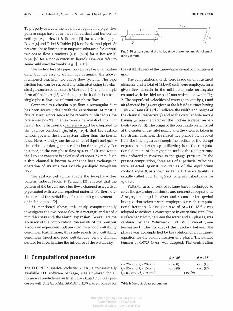
The computational grids were made up of structured elements and a total of 132,440 cells were employed for a given flow domain in the millimeterscale rectangular channel with the thickness of 2 mm which is shown in Fig. 2. The superficial velocities of water (denoted by jw) and air (denoted by jg) were given at the left side surface having 10W × 2H mm (W and H indicate the width and height of the channel, respectively) and at the circular hole nozzle having φ5 mm diameter on the bottom surface, respectively (see Fig. 2). The origin of the coordinate system is set at the center of the inlet nozzle and the xaxis is taken in the stream direction. The mixed twophase flow injected from the inlets passes through the section of the abrupt expansion and ends up outflowing from the computational domain. At the right side surface the total pressure was enforced to converge to the gauge pressure. In the present computation, three sets of superfacial velocities were selected against two values of the equilibrium contact angle θc as shown in Table I. The wettability is usually called poor for θc ≥ 90° whereas called good for θc < 90°.
FLUENT uses a controlvolumebased technique to solve the governing continuity and momentum equations. A segregated implicit solver and secondorder upwind interpolation scheme were employed for each computational iteration. A timestep size of 41.0 10t −Δ = × s was adopted to achieve a convergence in every time step. Free surface behaviour, between the water and air phases, was captured by the VolumeofFluid (VOF) model (Geo Reconstruct). The tracking of the interface between the phases was accomplished by the solution of a continuity equation for the volume fraction of a phase. The surface tension of 0.0727 (N/m) was adopted. The contribution
Fig. 2: Physical setup of the horizontally placed rectangular channel (units in mm).
θc = 30° θc = 147°
jg = 20 cm/s, jw = 28 cm/s case (I) case (III)jg = 80 cm/s, jw = 10 cm/s case (II) case (IV)jg = 0.0 cm/s, jw = 28 cm/s case (V)
Table I: Computational parameters.
Brought to you by | De Gruyter / TCSAuthenticated | 173.9.48.25
Download Date | 11/5/12 8:52 PM

Y. Ueda et al., Numerical Simulation of Gas-Liquid Part 1 407
of a volume force from a wall adhesion was added to the momentum equation as the source term, i.e.,
σ rκ α r r= +vol [ ]/[(1 / 2)( )]ij i i i jF ∇ with the curvature κ = ⋅∇ n and the surface normal n = ∇α. Here, ri was the density of the liquid i and σij the surface tension coefficient. The wettability was taken into account using the geometrical condition cos sinw c w cθ θ= +n n t on the contact line where nw and tw were the normal and tangential vectors on a wall. In this computation, we adopted the sufficiently small timestep Δt during the bubble deformation. This allowed us to employ the following Laplace–Young equation: Δp = σ12(κ1 + κ2), where Δp is the pressure difference between the two fluids. The convergence of the computational solution was determined based on residuals for the continuity and x, y, zvelocities. The residual of all quantities was set to 10−4. The solution was considered to be converged when all of the residuals were less than or equal to these default settings (see FLUENT 6.2 User’s Guide [24] for more details).
III Results
A For good wettability (θc = 30°)
Figure 3 shows a comparison of the flow patterns for two sets of the superfacial velocities (i.e., cases (I) and (II)) between the present computation and the previous experimental photographs [23]. Note that the flow direction is taken to be inverse in the experiment. The present computation seems to give similar flow patterns against the experimental photographs around the section of the
abrupt expansion. In downstream far from the expansion, the present computed results would immediately recover a pressure drop caused by the expansion, because the outflow condition is enforced on the outlet surface of 50W × 2H mm (see Fig. 2) whilst the working fluids outflow through the outlet nozzle of φ5 mm diameter in the experiment [23]. Therefore, in the computed result of Fig. 3 (a), the bubble fragments structure due to the expansion ends up growing to the slug flow in downstream region unlike the experimental result of Fig. 3 (b). The relationship between the flow pattern and the pressure field caused by the expansion is discussed below.
The pressure drop at the expansion is a key quantity to affect the flow pattern. To discuss this, the single phase flow with the same jw as case (I) and zero jg is computed as case (V). Figure 4 shows the pressure p and pressure drop −dp/dx of case (V) on the centerline of the channel. As observed in Fig. 4, the pressure drop increases with x in the upstream duct and approaches the fully developed flow whose pressure is 830 Pa/m. The pressure drop suddenly increases at the expansion and then decreases rapidly. In particular, the pressure drop becomes weaker in downstream of x ≳∼ 200 mm than that in the upstream of the expansion, i.e., the effect of the expansion affects the region of x ≲∼ 200 mm from the expansion and the memory ends up being lost in the downstream. Therefore, the fragments of the bubble due to the expansion stagnate around x ≲∼ 200 mm from the expansion, and in a further downstream (x ≳∼ 200 mm) the bubble fragments recover to the original nature, i.e., slug flow (see Fig. 3 (a)). Indeed, Kumagai & Iguchi [25] showed that the situation of case (I) exhibits the slug flow in the same rectangular channel without the expansion.
Fig. 3: Comparison of flow patterns for cases (I) and (II) between the present computation (air phase colored) and the previous experimental photographs [23]. Note that the stream direction is inverse between the computation and experiment.
Brought to you by | De Gruyter / TCSAuthenticated | 173.9.48.25
Download Date | 11/5/12 8:52 PM

408 Y. Ueda et al., Numerical Simulation of Gas-Liquid Part 1
As mentioned in the introduction, the pipe friction loss of the twophase flow can be estimated using the Lockhart & Martinelli [12] parameter and its simple form of Chisholm [13] on the basis of a singlephase flow. In contrast, twophase flow models of pressure recovery across an abrupt expansion are listed in Table 1 of Ahmed et al. [26] together with their revised model. To use these models on the present results, the timeaveraged void fraction α is needed, and unfortunately the quantity is not calculated here. This study mainly addresses computational flow patterns caused by the abrupt expansion in a narrow rectangular channel, and the quantitative discussion about the pressure drop is required for a future study.
Figure 5 shows the contour of the void fraction at the first bubble passing through the expansion. Note that the void fraction α = 0 indicates the water phase and α = 1 the air phase. The slug bubbles successively pass through the expansion and the bubbles are broken into fragments due to the pressure drop across the expansion. As mentioned in Fig. 4, the effect of the pressure drop due to the expansion recovers around x = 200 mm so that, although the bubble fragments stagnate within x ≲∼ 200 mm, these fragments can merge behind x ≈ 200 mm and grow to the slug bubble (see Fig. 3 (a)). For reference, the pressure distribution of Fig. 3 (a) on the centerline is displayed in Fig. 6. The pressure seems to fluctuate due to the air phase of moving bubbles.
Under a high airflow rate condition (i.e., case (II)), the flow pattern ahead of the expansion is observed to exhibit the annular (see Fig. 3 (c)). Therefore, this airflow behaves like a jet injected from a nozzle downstream of the expansion, and the flow pattern also forms the annular in downstream of the expansion. Indeed, the experimental results of Kumagai & Iguchi [25] is shown to be the annular under this condition without the expansion.
B For poor wettability (θc = 147°)
As mentioned in the introduction, the surface wettability is known to affect the meniscus of the airwater twophase flow in a narrow channel because the thickness of the present channel, 2 mm, is narrower than the Laplace constant of 2.7 mm. In Fig. 7, the meniscus patterns within two narrow plates are sketched for good (θc = 30°) and poor (θc = 147°) wettabilities. Therefore, as seen in Fig. 8 (a), case (III) behaves like the annular flow, which is different from case (I) (Kumagai & Iguchi [25] named such a kind of phenomenon the channeling). The vector plots (larger
Fig. 5: Selected snapshots of bubble deformation (void fraction) at the expansion for case (I) at (top): t = 0.4 s, (middle): t = 0.5 s and (bottom): t = 0.6 s.
Fig. 6: Pressure p on the centerline of the channel for case (I). The abrupt expansion is located at the dot-dashed line.
Fig. 4: Pressure p and pressure drop −dp/dx on the centerline of the channel for a single-phase flow (case (V)). The abrupt expansion is located at the dot-dashed line.
Brought to you by | De Gruyter / TCSAuthenticated | 173.9.48.25
Download Date | 11/5/12 8:52 PM

Y. Ueda et al., Numerical Simulation of Gas-Liquid Part 1 409
velocity plots than 0.4 m/s are erased for facilitating view) and the contour line of the pressure are shown in Fig. 8 (c) and (e). The high airflow rate of case (IV) can produce an intriguing nature that water phase behaves like droplets moving in the air phase due to the large jg from the nozzle (see Fig. 8 (b)). These droplets grows to slug drops due to merging themselves downstream of about x = 200 mm where the pressure drop due to the expansion recovers (see Fig. 4). In addition, the corresponding vector plots
(Similar to Fig. 8 (c), larger velocity plots than 0.45 m/s are erased) and the pressure contour are shown in Fig. 8 (d) and (f).
Figure 9 shows the process of the air phase growing to the channeling at the first bubble passing through the expansion. Unlike the result of Fig. 5 about case (I), the air phase cannot be fragmented at the expansion due to the meniscus of the poor wettability (see Fig. 7), and the channeling of the air phase is formed downstream of the expansion.
IV Concluding remarksThis study has implemented the FLUENT computation for gasliquid twophase flow in horizontally placed hydrophilic or hydrophobic rectangular channels with an
Fig. 7: Meniscus within two narrow plates. The water phase is colored in gray.
Fig. 8: Flow patterns for cases (III) and (IV). Note that, in the vector plots, larger velocity plots than 0.4 m/s for (c) and 0.45 m/s for (d) are erased for facilitating view.
Brought to you by | De Gruyter / TCSAuthenticated | 173.9.48.25
Download Date | 11/5/12 8:52 PM

410 Y. Ueda et al., Numerical Simulation of Gas-Liquid Part 1
abrupt expansion. These rectangular channels have a thickness narrower than the Laplace constant of this target system. Main findings are as follows:
– Under the good wettability condition, the flow patterns downstream of the expansion were classified into two within the present experimental conditions, i.e., the bubble fragments pattern for the low jg (case (I)) and the annularlike flow pattern for the high jg (case (II)). These computed flow patterns were in nice agreement with the previous experimental results [23].
– The fragments of the bubble in case (I) grows to slug bubbles in downstream due to pressure recovery of the channel flow.
– Under the poor wettability condition, the meniscus affects the flow pattern because of the narrower thickness of the channel than the Laplace constant. In the low jg (case (III)), the water phase forms the channeling whereas the water phase behaves like droplets moving in the air phase (case (IV)).
Unfortunately, there is no experimental data under a poor wettability condition about these kinds of rectan
gular ducts with an abrupt expansion. To properly verify the present computational results of cases (III) and (IV), the experiment needs to be carried out.
Received: March 16, 2012. Accepted: July 10, 2012.
References[1] G.I. Taylor, J. Fluid Mech., 10, 161–165 (1961).[2] R.M. Davies and G.I. Taylor, Proc. R. Soc. Lond., A200, 375–390
(1950).[3] G.F. Hewitt and D.N. Roberts, United Kingdom Atomic Energy
Authority (UKAEA) Report, AERE-M2159 (1969).[4] O. Baker, Oil and Gas J., 53, 185–190 (1954).[5] Y. Taitel and A.E. Dukler, AIChE J., 22, 47–55 (1976).[6] S. Waelchli, P. Rudolf and R. von Rohr, Int. J. Multiphase Flow,
32, 791–806 (2006).[7] K.A. Triplett, S.M. Ghiaasiaan, S.I. Abdel-Khalik and D.L.
Sadowski, Int. J. Multiphase Flow, 25, 377–394 (1999).[8] U. Kadri, M.L. Zoeteweij, R.F. Mudde and R.V.A. Oliemans, Int. J.
Multiphase Flow, 35, 439–449 (2009).[9] M. Dziubinski, H. Fidos and M. Sosno, Int. J. Multiphase Flow,
30, 551–563 (2004).[10] The Japan Society of Mechanical Engineers, Handbook of
gas-liquid two-phase flow technology, Corona press, (2006).[11] M. Iguchi and O.J. Ilegbusi, Modeling multiphase materials
processes, Springer, (2010).[12] R.W. Lockhart and R.C. Martinelli, Chem. Eng. Prog., 5, 39–48
(1949).[13] D. Chisholm, Int. J. Heat Mass Transfer, 10, 1767–1778 (1967).[14] J.L. Xu, P. Cheng and T.S. Zhao, Int. J. Multiphase Flow, 25,
411–432 (1999).[15] H.J. Lee and S.Y. Lee, Int. J. Multiphase Flow, 27, 783–796
(2001).[16] H.J. Lee and S.Y. Lee, Int. J. Multiphase Flow, 27, 2043–2062
(2001).[17] M. Sadatomi, M.I. Ali and M. Kawaji, Trans. JSME, (B) 58-546,
408–415 (1992).[18] T. Sawai, M. Kaji and G. Matsui, Trans. JSME, (B) 71-710,
2427–2433 (2005).[19] F. Aloui and M. Souhar, Int. J. Multiphase Flow, 22, 849–861
(1996).[20] I.M. Ali, M. Sadatomi and M. Kawaji, Can. J. Chem. Eng., 71,
657–666 (1993).[21] M. Iguchi and Y. Terauchi, Int. J. Multiphase Flow, 27, 729–735
(2001).[22] K. Fukushi and M. Iguchi, J. JSEM, 4, 192–197 (2004).[23] T. Oke, T. Kumagai and M. Iguchi, J. JSEM, 10, 32–37 (2010).[24] FLUENT 6.2 User’s Guide, Fluent Inc., Lebanon, NH (2005).[25] T. Kumagai and M. Iguchi, J. JSEM, 7, 50–55 (2007).[26] W.H. Ahmed, C.Y. Ching and M. Shoukri, Int. J. Multiphase Flow,
33, 575–594 (2007).
Fig. 9: Selected snapshots of bubble deformation (void fraction) at the expansion for case (III) at (top): t = 0.4 s, (middle): t = 0.5 s and (bottom): t = 0.6 s.
Brought to you by | De Gruyter / TCSAuthenticated | 173.9.48.25
Download Date | 11/5/12 8:52 PM


![0855-1147 (Tab C Exs. 26-38] (PUBLIC)](https://img.pdfslide.net/doc/110x75/549270caac795906168b47a0/0855-1147-tab-c-exs-26-38-public.jpg)