Embed Size (px)
Citation preview

NUMERICAL SIMULATION OF OSCILLATORY FLOW
AND CURRENT AROUND A CIRCULAR CYLINDER
Julio R. MeneghiniDepartment of Mechanical Engineering, University of Sao Paulo, BrazilCesareo de La Rosa SiqueiraDepartment of Naval Engineering, University of Sao Paulo, BrazilP. W BearmanImperial College of Science, Technology & Medicine, Department ofAeronautics, London, UK
Abstract — The proposed paper aims to present a parametrical analysis viaCFD (Computational Fluid Dynamics) of the drag amplification factor of acylinder in a current superposed to an in-line oscillatory velocity. Numericalsimulations based on a two-dimensional discrete vortex method with viscousdiffusion have been carried out in order to obtain the drag amplificationfactor against Uc/U/ (the relation between the uniform velocity Uo and theoscillatory-velocity amplitude /7/) for various values of KC (the Keulegan-Carpenter number). This work is related with fundamental research regardinghydrodynamics aspects of marine risers. The results obtained in this paper canbe applied in the analysis of marine risers concerning vortex shedding andflow-induced vibration. The parametrical analysis provides a bettercomprehension of the drag amplification phenomena when a circular cylinderis submersed in current with a superposed oscillatory flow. The amplificationcoefficient obtained can be used in a parametric form in the analysis of theforce coefficients present in mooring systems. The results obtained via CFDare in good agreement with those provided by a theoretical curve for therange of values of f///% A0 in which this curve applies. For values ofUj/Uo 1-0, the numerical simulations are compared to a second theoreticalequation and they show some dependence on KC, effect not predict for thisequation. The attraction of applying numerical methods to such problem isthat the flow can be studied in closer detail. The study of the drag
Transactions on the Built Environment vol 29, © 1997 WIT Press, www.witpress.com, ISSN 1743-3509

64 Offshore Engineering
amplification factor has relevant significance in the analysis of marine risers.In this sense, fundamental knowledge can be achieved performing aparametrical analysis of the phenomena in a relative fast way via CFD.
1. INTRODUCTION
A circular cylinder immersed on an oscillatory flow superposed to a current isknown to experience an amplification of the drag coefficient when comparedto the case where only a current is present^. This amplification phenomenoncan be very important in practical cases in Marine Technology, e.g. inmooring systems. Forces on cylinders in oscillatory flow has been extensivelyinvestigated by Bearman et. al. [15], Sarpkaya [16], among others. In Lin et.al. [17], a numerical study of oscillatory flow about a circular cylinder iscarried out for low values of Beta parameter (relation between Reynolds andKeulegan-Carpenter numbers).
In this paper numerical simulations based on a two-dimensional discretevortex method with viscous diffusion have been carried out in order to obtainthe drag amplification factor, Cd/Cds, defined by the relation between thedrag coefficient of a cylinder in current plus a in-line oscillatory velocity andthe drag coefficient of a cylinder in uniform flow\ This factor was plottedagainst U(/Ui (the relation between uniform velocity Uo and oscillatory-velocity amplitude U/) for various values of KC (the Keulegan-Carpenternumber).
The Keulegan-Carpenter number is defined by:
Ar=(/,77D (1)
where 7 the oscillation period and D the cylinder diameter.
The following table gives a summation of the cases simulated in theparametrical analysis performed in this work. Several values of the KeuleganCarpenter number KC and the relation between U<y'Uj were considered forthis purpose.
Transactions on the Built Environment vol 29, © 1997 WIT Press, www.witpress.com, ISSN 1743-3509
Offshore Engineering 65
KC (KeuleganCarpenternumber)
2712712712%2%27T271271
271
(//(//
4.03.02.0
1.51.00.750.700.60
0.50
KC (KeuleganCarpenternumber)
271271471471471471
471471
471
(/</(/,
0.400.303.02.0
1.51.00.750.5
0.25
KC (KeuleganCarpenternumber)
471671671
6n6n671671671
OWV,
4.0
1.0
0.750.70
0.600.500.400.30
Table 1- Cases simulated in the parametrical analysis of the drag amplificationfactor Cd/Cds.
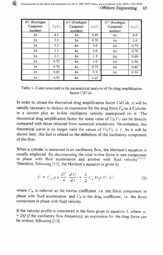
In order to obtain the theoretical drag amplification factor Cd/Cds, it will be
initially necessary to deduce an expression for the drag force Fj on a Cylinderin a current plus an in-line oscillatory velocity superposed on it. The
theoretical drag amplification factor for some value of Uo/Uj can be directlycompared with those obtained from numerical simulations. Nevertheless, this
theoretical curve is no longer valid for values of l/o/Uj < 1. As it will beshown later, this fact is related to the definition of the oscillatory componentof the flow.
When a cylinder is immersed in an oscillatory flow, the Morison's equation isusually employed for decomposing the total in-line force in one componentin phase with fluid acceleration and another with fluid velocity^™'^Therefore, following [13], the Morison's equation is given by
(2)
where C%, is referred as the inertia coefficient, i.e. the force component in
phase with fluid acceleration, and C<j is the drag coefficient, i.e. the forcecomponent in phase with fluid velocity.
If the velocity profile is considered in the form given in equation 3, where co= 2nf(ft\\Q oscillatory flow frequency), an expression for the drag force canbe written, following [13]:
Transactions on the Built Environment vol 29, © 1997 WIT Press, www.witpress.com, ISSN 1743-3509

66 Offshore Engineering
U=Uo+
T P U
(3)
(4)
Using equations (3) e (4) and properties of cos*o> t another expression for Fjcan be obtained as follows:
(5)F * - P C*0l/.» + *V + 20.17,
Taking the average value of Fj in equation (4) we obtain:
(6)
From the definition of drag coefficient,
we finally obtain the drag amplification factor for a given Uj/Uo relation:
i u,
-'ds
(7)
(8)
There is one point that should be stressed here: for U(/Ui < I there is aninversion of the velocity profile in some time intervals during the oscillationperiod. In this way, the equation (8) is no longer valid, since in this intervalthe force change its direction.
In order to obtain an expression valid for U(/Uj < 1, Morison's equation canbe integrated taking into consideration the phase in a cycle for which the totalvelocity is zero. This phase angle, indicated by </>, can be obtained by equatingexpression (3) to zero. This gives an expression for the drag amplificationfactor in the form:
Transactions on the Built Environment vol 29, © 1997 WIT Press, www.witpress.com, ISSN 1743-3509
Offshore Engineering 67
where ̂ = cos'(-U</Ui).
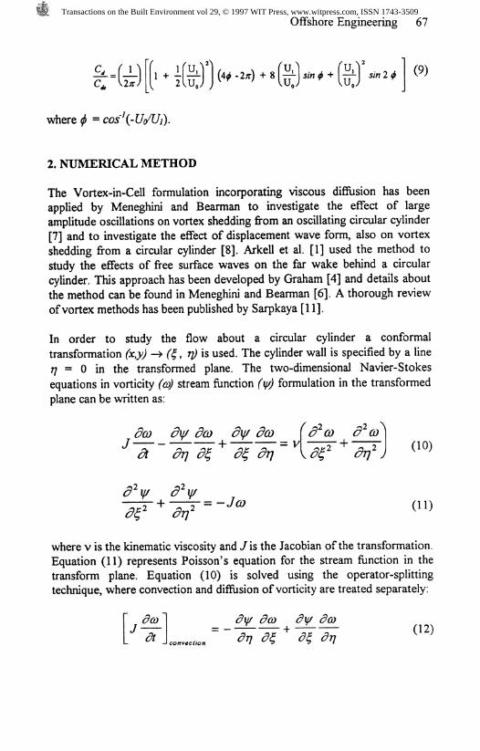
2. NUMERICAL METHOD
The Vortex-in-Cell formulation incorporating viscous diffusion has beenapplied by Meneghini and Bearman to investigate the effect of largeamplitude oscillations on vortex shedding from an oscillating circular cylinder[7] and to investigate the effect of displacement wave form, also on vortexshedding from a circular cylinder [8]. Arkell et al. [1] used the method tostudy the effects of free surface waves on the far wake behind a circularcylinder. This approach has been developed by Graham [4] and details aboutthe method can be found in Meneghini and Bearman [6]. A thorough reviewof vortex methods has been published by Sarpkaya [11].
In order to study the flow about a circular cylinder a conformaltransformation fay) -> (g, TJ) is used. The cylinder wall is specified by a line77 = 0 in the transformed plane. The two-dimensional Navier-Stokesequations in vorticity (CD) stream function (if/) formulation in the transformedplane can be written as:
dco dy dco dy dco
01)
where v is the kinematic viscosity and J is the Jacobian of the transformation.Equation (11) represents Poisson's equation for the stream function in thetransform plane. Equation (10) is solved using the operator-splittingtechnique, where convection and diffusion of vorticity are treated separately:
" da>~\ dy dco dy da" = ~~ * ~
Transactions on the Built Environment vol 29, © 1997 WIT Press, www.witpress.com, ISSN 1743-3509
68 Offshore Engineering
Jdt
<?:# <?V• + (13)
J diffusion \ ̂ y "'I '
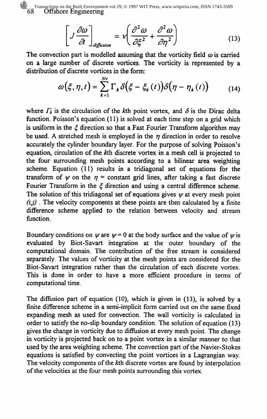
The convection part is modelled assuming that the vorticity field CD is carriedon a large number of discrete vortices. The vorticity is represented by adistribution of discrete vortices in the form:
where /* is the circulation of the Ath point vortex, and 5 is the Dirac deltafunction. Poisson's equation (11) is solved at each time step on a grid whichis uniform in the £ direction so that a Fast Fourier Transform algorithm maybe used. A stretched mesh is employed in the 77 direction in order to resolveaccurately the cylinder boundary layer. For the purpose of solving Poisson'sequation, circulation of the kth discrete vortex in a mesh cell is projected tothe four surrounding mesh points according to a bilinear area weightingscheme. Equation (11) results in a tridiagonal set of equations for thetransform of \{/ on the 77 = constant grid lines, after taking a fast discreteFourier Transform in the £ direction and using a central difference scheme.The solution of this tridiagonal set of equations gives %f at every mesh point(ij) . The velocity components at these points are then calculated by a finitedifference scheme applied to the relation between velocity and streamfunction.
Boundary conditions on y are %f= 0 at the body surface and the value of y/isevaluated by Biot-Savart integration at the outer boundary of thecomputational domain. The contribution of the free stream is consideredseparately. The values of vorticity at the mesh points are considered for theBiot-Savart integration rather than the circulation of each discrete vortex.This is done in order to have a more efficient procedure in terms ofcomputational time.
The diffusion part of equation (10), which is given in (13), is solved by afinite difference scheme in a semi-implicit form carried out on the same fixedexpanding mesh as used for convection. The wall vorticity is calculated inorder to satisfy the no-slip boundary condition. The solution of equation (13)gives the change in vorticity due to diffusion at every mesh point. The changein vorticity is projected back on to a point vortex in a similar manner to thatused by the area weighting scheme. The convection part of the Navier-Stokesequations is satisfied by convecting the point vortices in a Lagrangian way.The velocity components of the kth discrete vortex are found by interpolationof the velocities at the four mesh points surrounding this vortex.
Transactions on the Built Environment vol 29, © 1997 WIT Press, www.witpress.com, ISSN 1743-3509
Offshore Engineering 69
3. FORCE EVALUATION
Force coefficients are calculated by suitably integrating the pressure and skinfriction contributions. After considering the contributions from skin frictionand pressure, the force components are resolved in the two directions (x,y) inthe physical plane , yielding F* and Fy . These forces are then non-dimensionalised as follows:
2F,
where p is the fluid density, and U is the free stream velocity.
4. RESULTS AND DISCUSSIONS
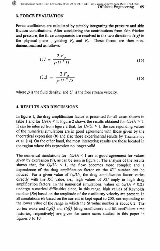
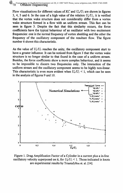
In figure 1, the drag amplification factor is presented for all cases shown intable 1 and for Ut/Uj < 1. Figure 2 shows the results obtained for U(/Ui > 1.It can be inferred from figure 2 that, for U(/Uj > 1, the corresponding valuesof the numerical simulations are in good agreement with those given by thetheoretical expression (8) and also those experimental results by Triantafyllouet. al. [14]. On the other hand, the most interesting results are those located inthe region where this expression no longer valid.
The numerical simulations for U</U/ < 1 are in good agreement for valuesgiven by expression (9), as can be seen in figure 1. The analysis of the resultsshows that, for U(/Uj < 1, the flow becomes more complex and adependence of the drag amplification factor on the KC number can benoticed. For a given value of £/</£/;, the drag amplification factor variesdirectly with the KC value, i.e., high values of KC imply in high dragamplification factors. In the numerical simulations, values of U(/Uj < 0.25undergo numerical difficulties since, in this range, high values of Reynoldsnumber (Re) based on the amplitude of the oscillatory velocity are present. Inall simulations Re based on the current is kept equal to 200, corresponding tothe lower value of the range in which the Strouhal number is about 0.2. The
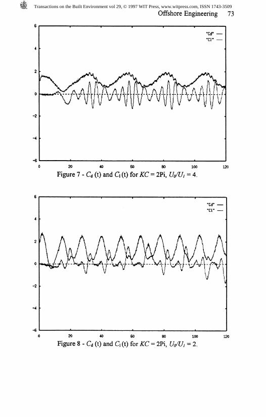
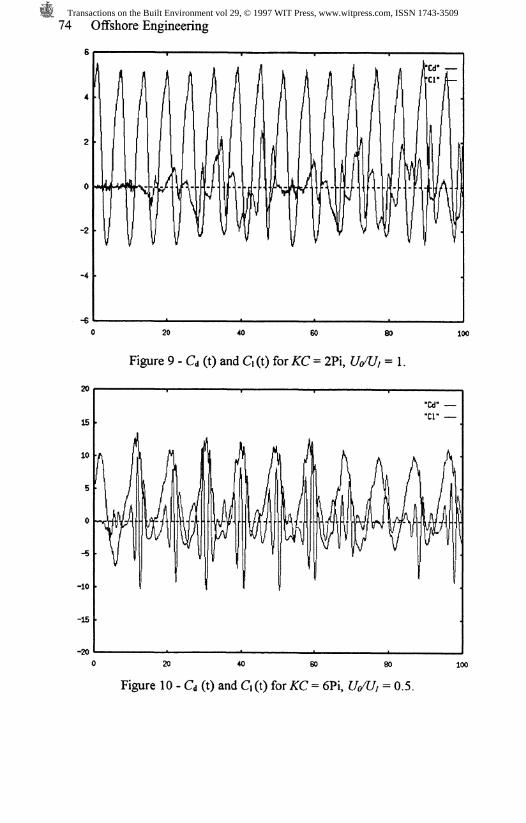
vortex wake and Cjft) and Cift) (drag coefficients and lift coefficient timehistories, respectively) are given for some cases studied in this paper infigures 3 to 10.
Transactions on the Built Environment vol 29, © 1997 WIT Press, www.witpress.com, ISSN 1743-3509
70 Offshore Engineering
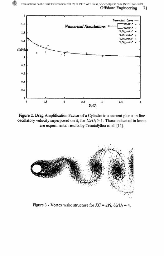
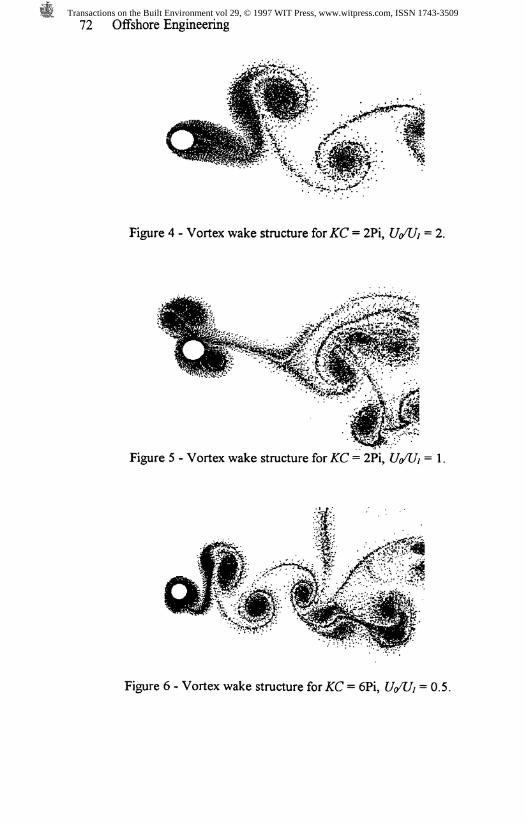
Flow visualisations for different values of KC and UJUi are shown in figures3, 4, 5 and 6. In the case of a high value of the relation t/</J7/, it is verifiedthat the vortex wake structure does not considerably differ from a vortexwake structure formed in a flow with an uniform stream. This fact can beseen in figure 3. Despite the fact that this similarity occurs, the forcecoefficients have the typical behaviour of an oscillator with two excitementfrequencies: one is the normal frequency of vortex shedding and the other thefrequency of the oscillatory component of the resultant flow. The figurenumber 6 shows this characteristic.
As the value of U</Uj reaches the unity, the oscillatory component start tohave a greater influence. It can be noticed from figure 3 that the vortex wakestructure is no longer similar to that found in the case of a uniform stream.Besides, the force coefficients show a more complex behaviour, and it seemsto be impossible to discern two frequencies only. The interaction of theuniform stream and the oscillatory component seems to be highly non-linear.This characteristic is even more evident when £/</£// < 1, which can be seenin the analysis of figures 9 and 10.
Cd/Cds4
Numerical Simulations
0.2 0.4 0.6
Theoretical Curve"KC=2Pi""KC=4Pi"
_"KC=GPi""0.50_knots""0.75_knots""l.OOJcnots-
0,8
Figure 1. Drag Amplification Factor of a Cylinder in a current plus a in-lineoscillatory velocity superposed on it, for U</Uj < 1. Those indicated in knots
are experimental results by Triantafyllou et. al. [14].
Transactions on the Built Environment vol 29, © 1997 WIT Press, www.witpress.com, ISSN 1743-3509
Offshore Engineering 71
2
1.8
1.6
1.4
c<#&&
1
0.8
0.6
0.4
0.2
0
Numerical Simulations
Theoretical Cirvc —"KC=2Pi""KC=4Pi"
"0.50_knoU'"0.75_knoW""l.OOJtnots*
1 1.5 2.5 3.5
Figure 2. Drag Amplification Factor of a Cylinder in a current plus a in-lineoscillatory velocity superposed on it, for U</Ui > 1. Those indicated in knots
are experimental results by Triantafyllou et. al. [14].
Figure 3 - Vortex wake structure for KC = 2Pi, U(/Uj = 4.
Transactions on the Built Environment vol 29, © 1997 WIT Press, www.witpress.com, ISSN 1743-3509
72 Offshore Engineering
Figure 4 - Vortex wake structure for KC = 2Pi, £/</£/; = 2.
Figure 5 - Vortex wake structure for KC = 2Pi, U</Ui = 1.
Figure 6 - Vortex wake structure for KC = 6Pi, U(/Ui = 0.5.
Transactions on the Built Environment vol 29, © 1997 WIT Press, www.witpress.com, ISSN 1743-3509
Offshore Engineering 73
"Cd" —"cr —
0 20 40 60 80Figure 7 - Cd (t) and C\ (t) for KC = 2Pi,
100
= 4.
120
-2
"Cd""Cl"
20 40 60 80 100Figure 8 - Cd (t) and C\ (t) for KC = 2Pi, U</Ui = 2.
120
Transactions on the Built Environment vol 29, © 1997 WIT Press, www.witpress.com, ISSN 1743-3509
74 Offshore Engineering
6
20
15
10
-10
-15
-20
20 40 60 80
Figure 9 - Cd (t) and d (t) for KC = 2Pi, WUj = 1.
100
"Cd""cr
20 GO
Figure 10 - Cd (t) and C, (t) for KC = 6Pi, Uo/Ui = 0.5.
Transactions on the Built Environment vol 29, © 1997 WIT Press, www.witpress.com, ISSN 1743-3509
Offshore Engineering 75
5. ACKNOWLEDGEMENTS
The first and second authors (JRM and CDLRS) are grateful to FAPESP (grant94/3057-0 and 94/3528-3) and PETROBRAS (Brazilian Oil Company) forproviding them a Research Grant for this project.
6. REFERENCES
[1] Arkell, R. H., Graham, J. M. R., and Zhou, C. Y. The effects of waves andmean flow on the hydrodynamic forces on circular cylinders, Proc. 6th BOSSConference, London, 1992.
[2] Blevins R. D., Flow Induced Vibration, Second edition, Van NostrandReinhold, New York, 1990.
[3] Brika, D., Laneville, A., Vortex-induced vibration of a long flexible circularcylinder, Journal of Fluid Mechanics, Vol. 259, pp. 481-508, 1993.
[4] Graham, J. M. R., Computation of viscous separated flow using a particlemethod, Numerical Methods in Fluid Mechanics, Vol.3, pp. 310-317,Ed. K.W.Morton, Oxford University Press, 1988.
[5] Khalak, A., and Williamson, C. H. K, Dynamics of a hydroelastic cylinder withvery low mass and damping, accepted for publication in the Journal of Fluidsand Structures.
[6] Meneghini, J R., and Bearman, P. W., Numerical simulation of control of bluffbody flow using a discrete vortex method incorporating viscous diffusion, Proc.IUTAMSymposium on Bluff-Body Wakes, Dynamics and Instabilities, pp. 257-262, Ed. H. Eckelmann, Springer-Verlag, 1992.
[7] Meneghini, J. R., and Bearman, P. W., Numerical simulation of high amplitudeoscillatory flow about a circular cylinder, Journal Fluids and Structures, Vol.9, pp. 435-455, 1995.
[8] Meneghini, J. R., and Bearman, P. W., Numerical simulation of the interactionbetween the shedding of vortices and square-wave oscillations applied to acircular cylinder, Proc. Second International Conference on Hydrodynamics,Vol. 2, pp.785-790, Ed. Chwang, Lee & Leung, Balkema, Hong Kong, 1996.
[9] Meneghini, J. R., Numerical Simulation of Bluff Body Flow Control Using aDiscrete Vortex Method, PhD thesis, University of London, UK, 1993.
[10] Parkinson, G., Phenomena and modelling of flow-induced vibrations of bluffbodies, Prog. Aerospace Sci., Vol. 26, pp. 169-224, 1989.
[ll]Sarpkaya, T, Computational methods with vortices - The 1988 FreemanScholar Lecture, J. Fluids Engineering, Vol. 111, pp. 5-52, 1989.
[12] Williamson, C.H.K. and Roshko, A., Vortex formation in the wake of anoscillating cylinder, J. Fluids and Structures, Vol. 2, pp 355-381, 1988.
[13]Garbis H. Keulegan & Lloyd H. Carpenter, Forces on Cylinders and Plates inan Oscillating Fluid, Journal of Research of the National Bureau of Standards,vol.60, No 5, Maio 1958, Research Paper 2857.
Transactions on the Built Environment vol 29, © 1997 WIT Press, www.witpress.com, ISSN 1743-3509

76 Offshore Engineering
[14]Triantaryilou, M.S., Yue, D.K.P., and Tein, D.Y.S., Damping of MooredFloating Structures, Proceeding of the 26th Offshore Technology Conference,Houston, USA, 1994.
[15]P.W. Bearman, M. J. Downie, J. M. R. Graham, E. D. Obasaju, Forces oncylinders in viscous oscillatory flow at low Keulegan-Carpenter numbers, J.FluidsAdfecA., Vol. 154, pp 337-356, 1985.
[16]Sarpkaya, T., Isaacson, M., Mechanics of wave forces on offshore structures.1981.
[17] X., W. Lin, P.W. Bearman, J. M. R. Graham, A Numerical Study ofOscillatory Flow About a Circular Cylinder for Low Values of Beta Parameter,J. Fluids and Structures, Vol. 10, pp 501-526, 1996.
Transactions on the Built Environment vol 29, © 1997 WIT Press, www.witpress.com, ISSN 1743-3509