Embed Size (px)
Citation preview
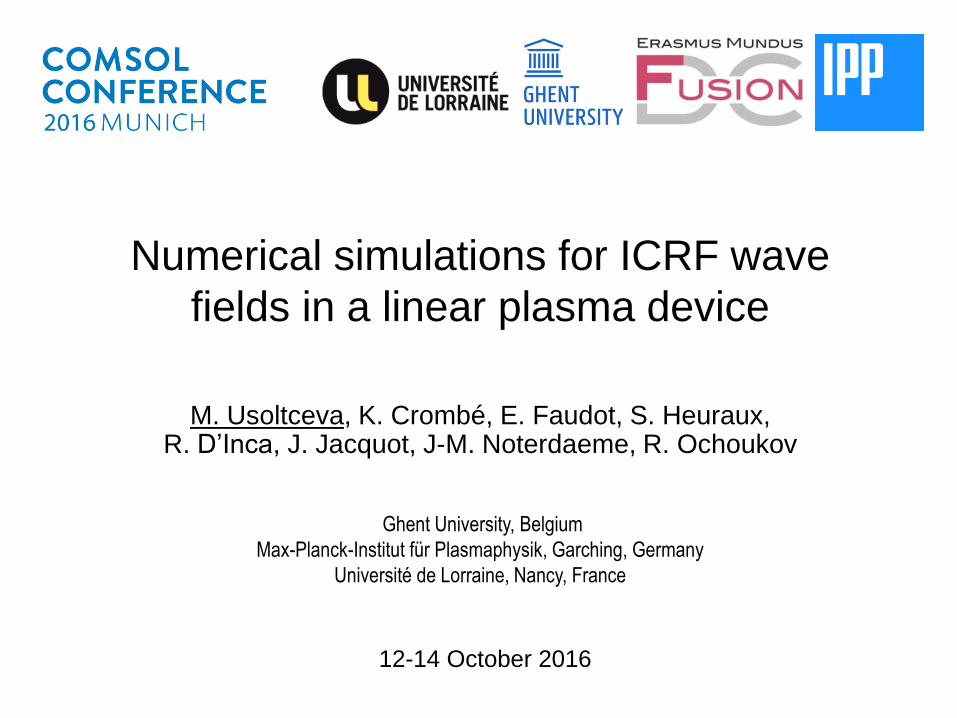
Numerical simulations for ICRF wave
fields in a linear plasma device
M. Usoltceva, K. Crombé, E. Faudot, S. Heuraux,R. D’Inca, J. Jacquot, J-M. Noterdaeme, R. Ochoukov
12-14 October 2016
Ghent University, Belgium
Max-Planck-Institut für Plasmaphysik, Garching, Germany
Université de Lorraine, Nancy, France
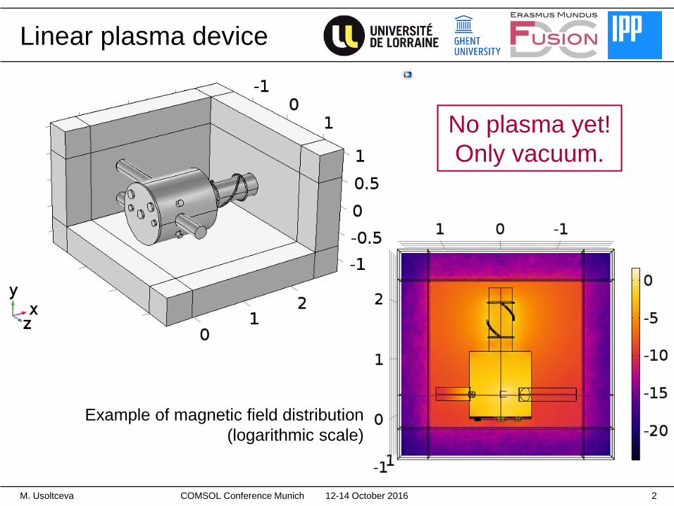
Linear plasma device
M. Usoltceva 2
No plasma yet!
Only vacuum.
Example of magnetic field distribution
(logarithmic scale)
12-14 October 2016COMSOL Conference Munich
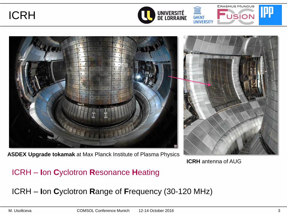
ICRH
12-14 October 2016M. Usoltceva 3
ASDEX Upgrade tokamak at Max Planck Institute of Plasma Physics
ICRH – Ion Cyclotron Resonance Heating
ICRH – Ion Cyclotron Range of Frequency (30-120 MHz)
ICRH antenna of AUG
COMSOL Conference Munich
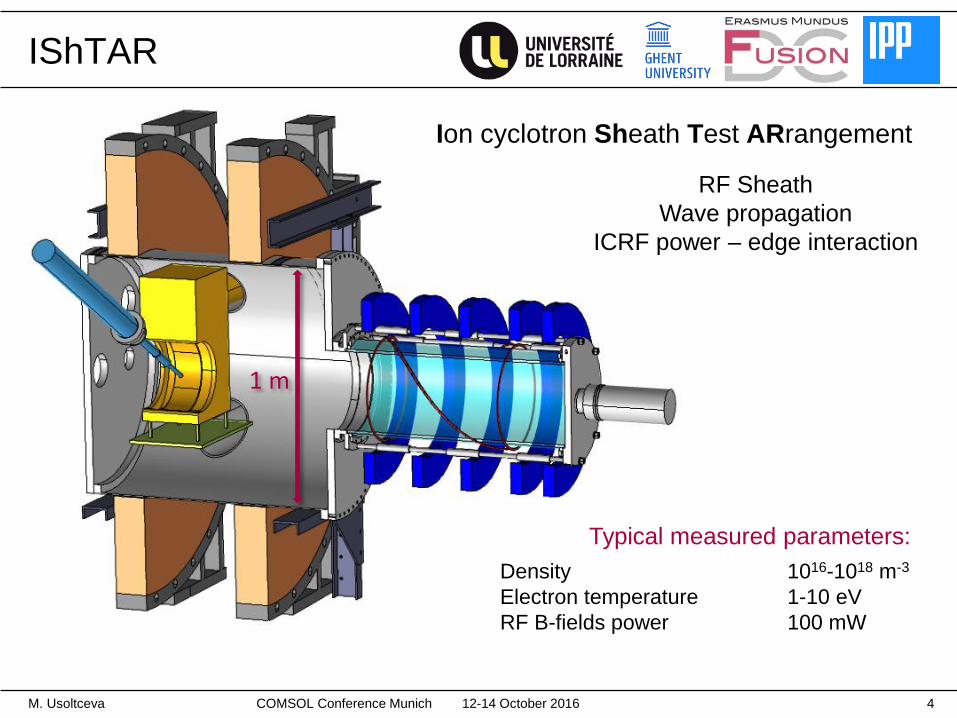
1 m
IShTAR
Ion cyclotron Sheath Test ARrangement
Typical measured parameters:
Density 1016-1018 m-3
Electron temperature 1-10 eV
RF B-fields power 100 mW
12-14 October 2016M. Usoltceva 4
RF Sheath
Wave propagation
ICRF power – edge interaction
COMSOL Conference Munich
12-14 October 2016M. Usoltceva 5
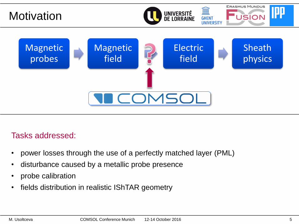
Motivation
Tasks addressed:
• power losses through the use of a perfectly matched layer (PML)
• disturbance caused by a metallic probe presence
• probe calibration
• fields distribution in realistic IShTAR geometry
Magnetic probes
Magnetic field
Electric field
Sheath physics
COMSOL Conference Munich
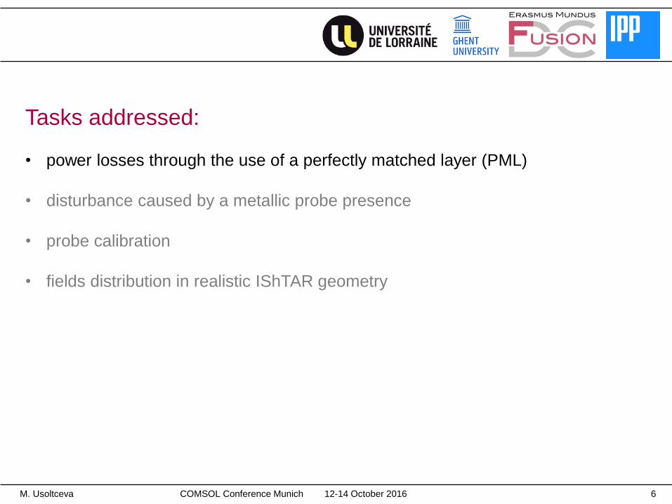
Tasks addressed:
• power losses through the use of a perfectly matched layer (PML)
• disturbance caused by a metallic probe presence
• probe calibration
• fields distribution in realistic IShTAR geometry
12-14 October 2016M. Usoltceva 6COMSOL Conference Munich
12-14 October 2016 7
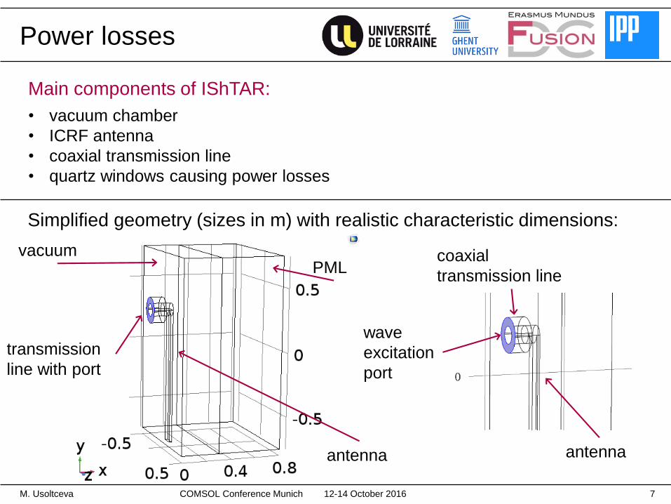
Simplified geometry (sizes in m) with realistic characteristic dimensions:
vacuumPML
transmission
line with port
antenna
coaxial
transmission line
wave
excitation
port
antenna
M. Usoltceva
Power losses
Main components of IShTAR:
• vacuum chamber
• ICRF antenna
• coaxial transmission line
• quartz windows causing power losses
COMSOL Conference Munich
12-14 October 2016M. Usoltceva 8
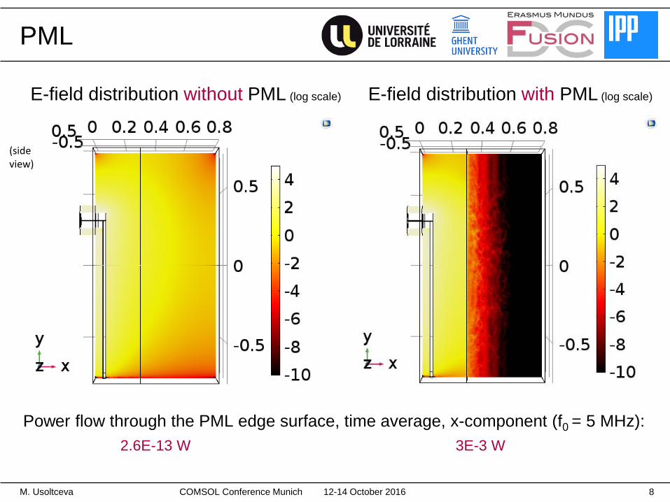
PML
Power flow through the PML edge surface, time average, x-component (f0 = 5 MHz):
2.6E-13 W 3E-3 W
(side view)
E-field distribution without PML (log scale) E-field distribution with PML (log scale)
COMSOL Conference Munich
Tasks addressed:
• power losses through the use of a perfectly matched layer (PML)
• disturbance caused by a metallic probe presence
• probe calibration
• fields distribution in realistic IShTAR geometry
12-14 October 2016M. Usoltceva 9COMSOL Conference Munich
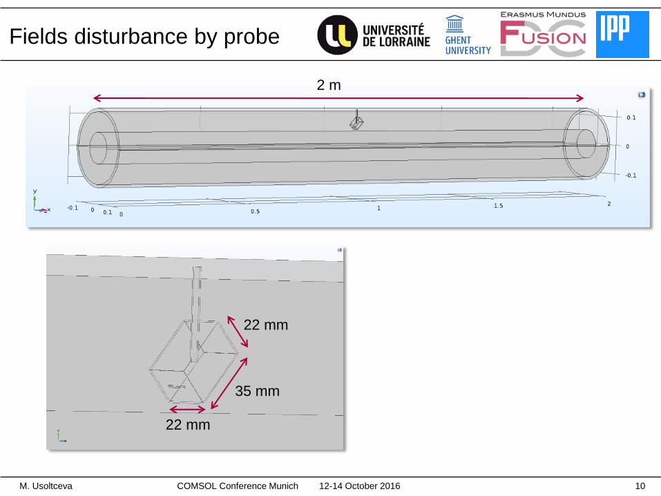
Fields disturbance by probe
12-14 October 2016M. Usoltceva 10
35 mm
22 mm
22 mm
2 m
COMSOL Conference Munich
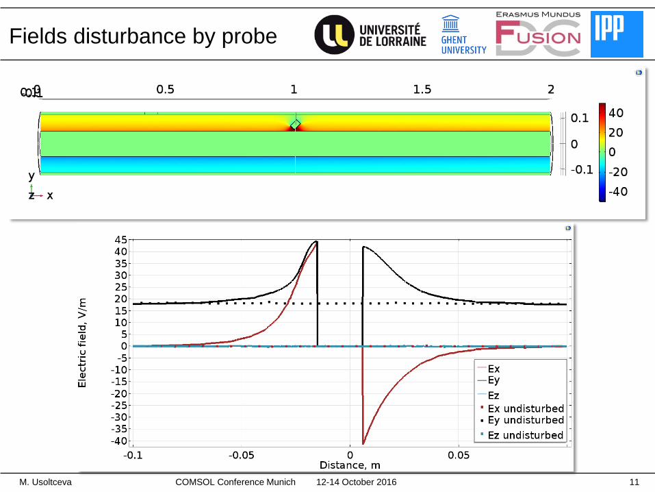
Fields disturbance by probe
12-14 October 2016M. Usoltceva 11COMSOL Conference Munich
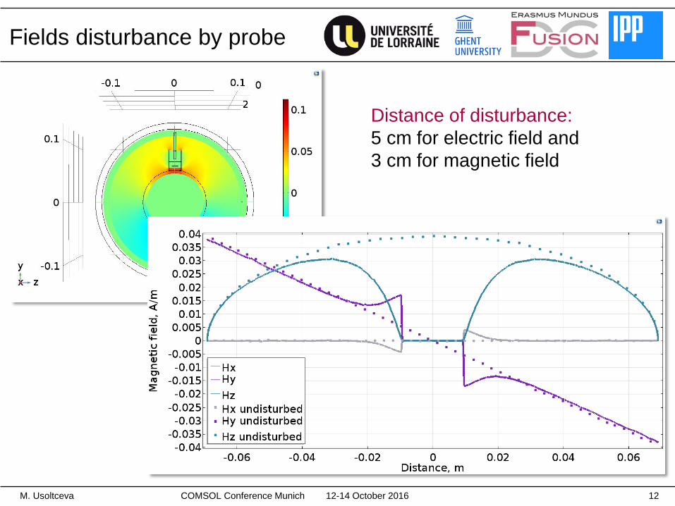
Fields disturbance by probe
Distance of disturbance:
5 cm for electric field and
3 cm for magnetic field
12-14 October 2016M. Usoltceva 12COMSOL Conference Munich
Tasks addressed:
• power losses through the use of a perfectly matched layer (PML)
• disturbance caused by a metallic probe presence
• probe calibration
• fields distribution in realistic IShTAR geometry
12-14 October 2016M. Usoltceva 13
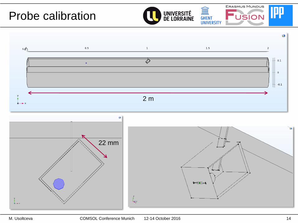
Probe calibration
12-14 October 2016M. Usoltceva 14
2 m
22 mm
COMSOL Conference Munich
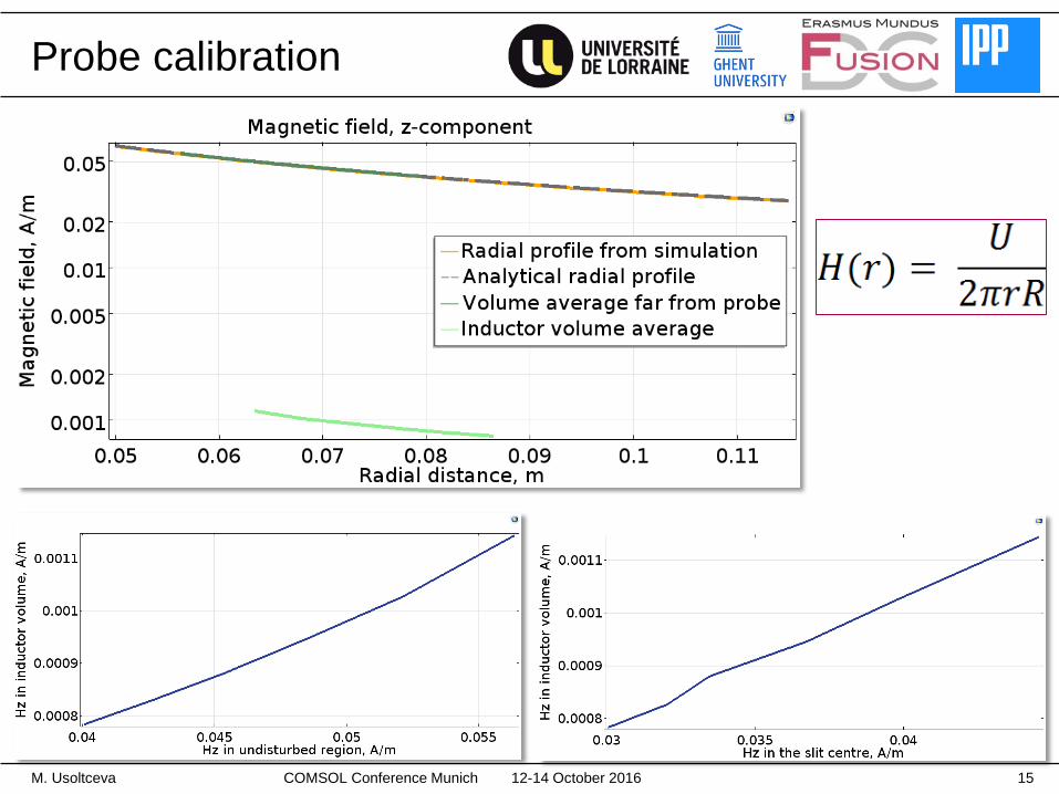
Probe calibration
12-14 October 2016M. Usoltceva 15COMSOL Conference Munich
Tasks addressed:
• power losses through the use of a perfectly matched layer (PML)
• disturbance caused by a metallic probe presence
• probe calibration
• fields distribution in realistic IShTAR geometry
12-14 October 2016M. Usoltceva 16COMSOL Conference Munich
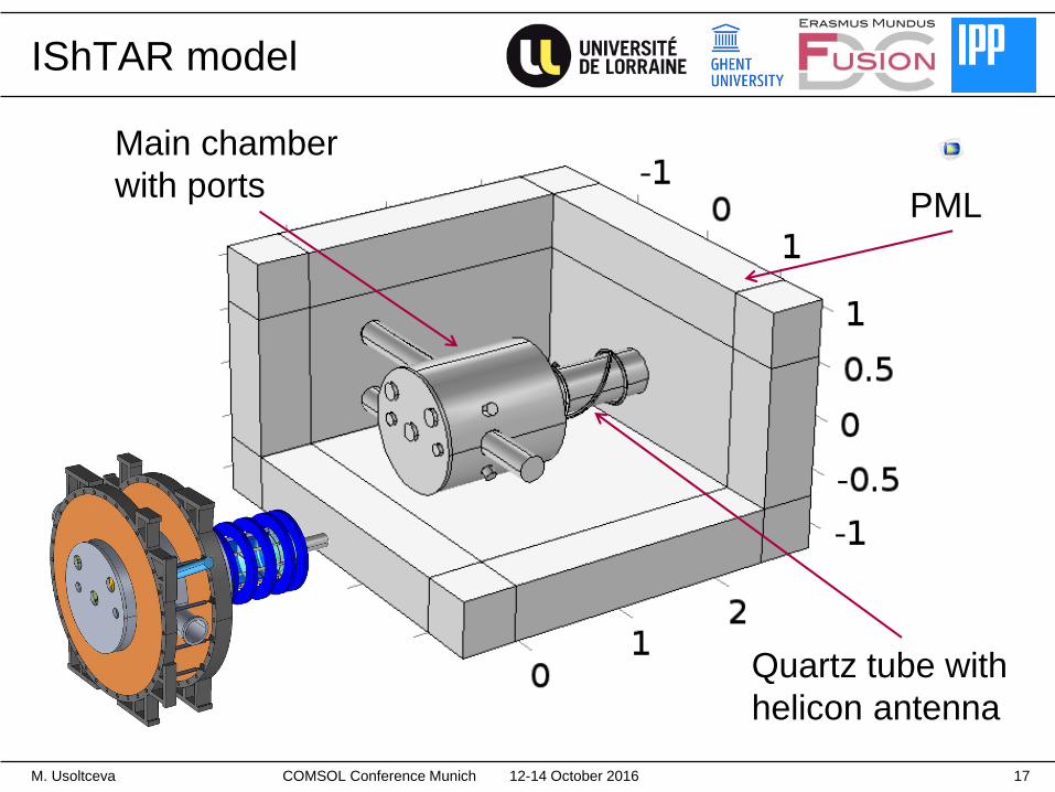
PML
Quartz tube with
helicon antenna
Main chamber
with ports
IShTAR model
12-14 October 2016M. Usoltceva 17COMSOL Conference Munich
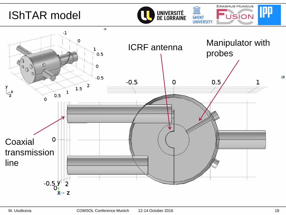
Manipulator with
probesICRF antenna
Coaxial
transmission
line
IShTAR model
12-14 October 2016M. Usoltceva 18COMSOL Conference Munich
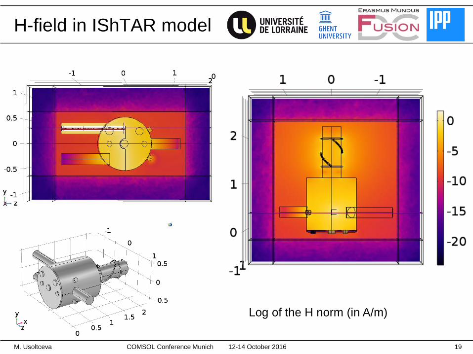
H-field in IShTAR model
Log of the H norm (in A/m)
12-14 October 2016M. Usoltceva 19COMSOL Conference Munich
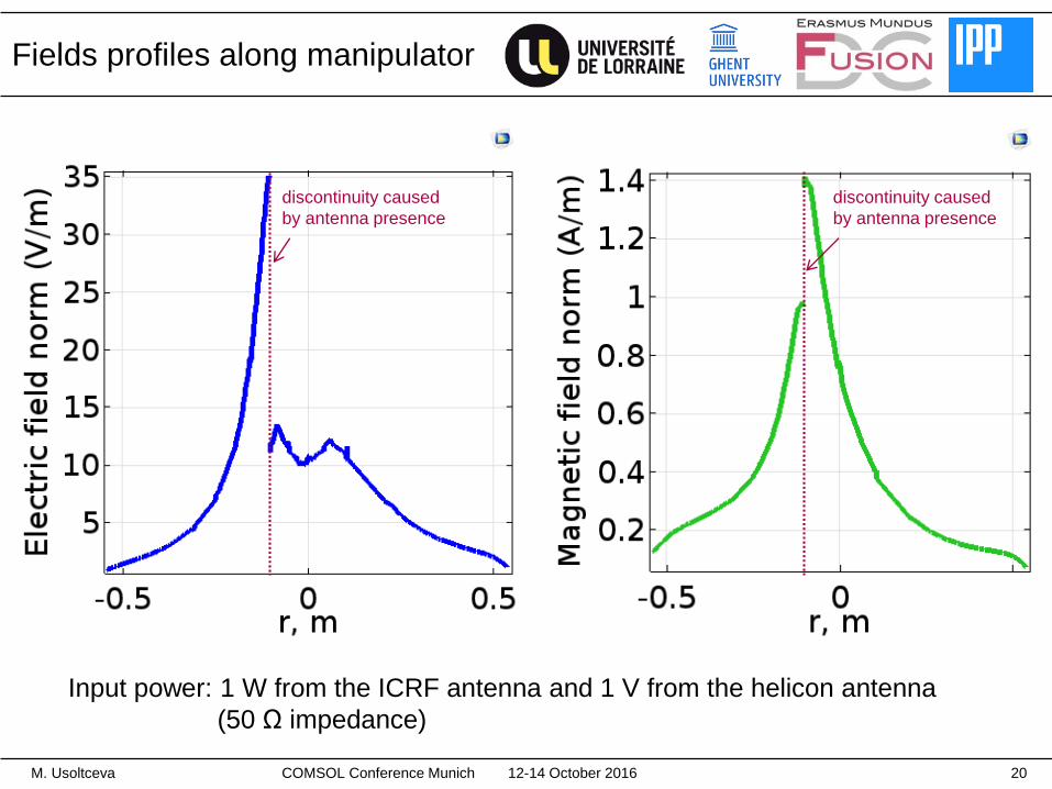
Fields profiles along manipulator
Input power: 1 W from the ICRF antenna and 1 V from the helicon antenna
(50 Ω impedance)
12-14 October 2016M. Usoltceva 20
discontinuity caused
by antenna presence
discontinuity caused
by antenna presence
COMSOL Conference Munich
Summary
COMSOL simulations provide necessary support for RF sheath studies
on IShTAR and complement experimental results from diagnostics.
Several tasks are completed in an attempt to approach the realistic
IShTAR conditions.
Modeling results are ahead of the experiments at the moment.
Future steps:
• Experimental data processing by using results from simulations.
• New antenna geometry implementation.
• Simulations in plasma instead of vacuum.
12-14 October 2016M. Usoltceva 21COMSOL Conference Munich
Appendix
12-14 October 2016M. Usoltceva 22COMSOL Conference Munich
12-14 October 2016M. Usoltceva 23
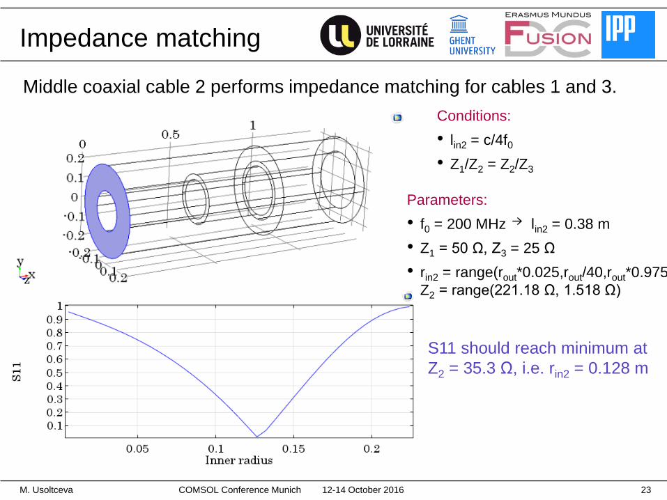
Impedance matching
Middle coaxial cable 2 performs impedance matching for cables 1 and 3.
Conditions:
• lin2 = c/4f0
• Z1/Z2 = Z2/Z3
Parameters:
• f0 = 200 MHz lin2 = 0.38 m
• Z1 = 50 Ω, Z3 = 25 Ω
• rin2 = range(rout*0.025,rout/40,rout*0.975)
Z2 = range(221.18 Ω, 1.518 Ω)
S11 should reach minimum at
Z2 = 35.3 Ω, i.e. rin2 = 0.128 m
COMSOL Conference Munich
12-14 October 2016M. Usoltceva 24
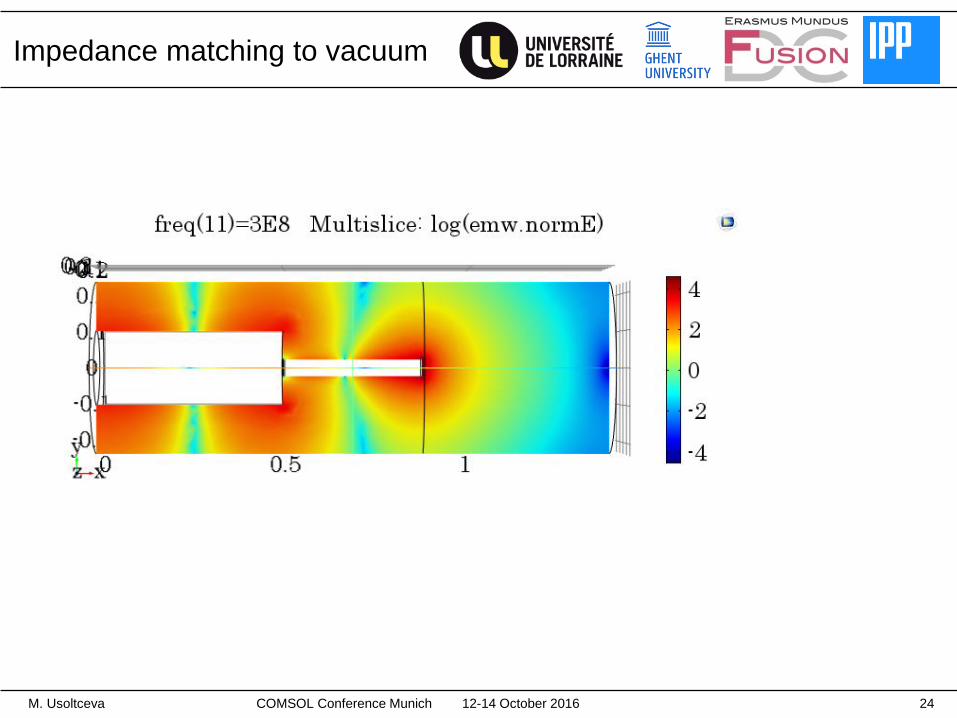
Impedance matching to vacuum
COMSOL Conference Munich
12-14 October 2016M. Usoltceva 25
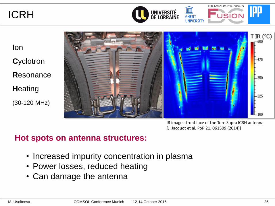
ICRH
Ion
Cyclotron
Resonance
Heating
(30-120 MHz)
IR image - front face of the Tore Supra ICRH antenna[J. Jacquot et al, PoP 21, 061509 (2014)]
Hot spots on antenna structures:
• Increased impurity concentration in plasma
• Power losses, reduced heating
• Can damage the antenna
COMSOL Conference Munich