Embed Size (px)
Citation preview
CORRESPONDENCE Pavel V. Bulat [email protected]
© 2016 Bulat and Volkov. Open Access terms of the Creative Commons Attribution 4.0 International License (http://creativecommons.org/licenses/by/4.0/) apply. The license permits unrestricted use, distribution, and reproduction in any medium, on the condition that users give exact credit to the original author(s) and the source, provide a link to the Creative Commons license, and indicate if they made any changes.
Introduction
A shock wave process (SWP) is a process of reorganizing a gas-dynamic
system with the parameters f into a system with the parameters f̂ , where f and
f̂ are a set of gas-dynamic variables before and behind SWP. These sets include
kinematic, thermodynamic and thermo-physical variables that define flow
parameters. Specifically, examples of the variables include kinematic
INTERNATIONAL JOURNAL OF ENVIRONMENTAL & SCIENCE EDUCATION
2016, VOL. 11, NO. 16, 9026-9038
Numerical Simulations of Shock Wave Refraction at Inclined Gas Contact Discontinuity
Pavel V. Bulata,b and Konstantin N. Volkovc
aNational Research University of Information Technologies, Saint Petersburg, RUSSIA; bMechanics and Optics University ITMO, Saint Petersburg, RUSSIA;
cKingston University, London, UNITED KINGDOM
ABSTRACT When a shock wave interacts with a contact discontinuity, there may appear a reflected rarefaction wave, a deflected contact discontinuity and a refracted supersonic shock. The numerical simulation of shock wave refraction at a plane contact discontinuity separating gases with different densities is performed. Euler equations describing inviscid compressible flow were discretized using the finite volume method on unstructured meshes and WENO schemes. Time integration was performed using a third-order Runge–Kutta method. The wave structure resulting from regular shock refraction is determined allowing its properties to be explored. In order to visualize and interpret the results of numerical calculations, a procedure for identifying and classifying gas-dynamic discontinuities was applied. The procedure employed dynamic consistency conditions and digital image processing methods to determine flow structure and its quantitative characteristics. The results of the numerical and experimental visualizations were compared (shadow patterns, schlieren images, interferograms). The results computed are in an agreement with the theoretical and experimental predictions of a regular refraction of a shock wave on an inclined contact discontinuity.
KEYWORDS ARTICLE HISTORY Shock wave refraction, computational dynamics,
finite volume method, unstructured mesh, contact discontinuity, level-set method
Received 03 March 2016 Revised 12 April 2016
Accepted 19 May 2016
OPEN ACCESS
INTERNATIONAL JOURNAL OF ENVIRONMENTAL & SCIENCE EDUCATION 9027
parameters (velocity, acceleration), thermodynamic parameters (pressure,
density, temperature, entropy, enthalpy), and thermo-physical parameters (heat
capacity, adiabatic index, viscosity), which can change during SWP.
The intensity of SWP is generally characterized by a ratio of static
pressures J = p1/p behind and before SWP (p1 is the static pressure behind SWP,
and p is the static pressure before SWP). In some cases, this is denoted as
ppJc ˆ/ , where p̂ is pressure behind SWP. The values Jc>1 describe flow
compression, while the values Jc < 1 describe flow expansion (rarefaction).
Gas-dynamic discontinuity (GDD) represents a certain idealization of an
area where parameters change discontinuously, replacing the area with surfaces
where gas-dynamic variables unevenly change (Uskov, Bulat & Arkhipova,
2014). GDDs in supersonic flows can be either zero-order or first order.
Examples of zero-order GDDs include compression wave, shock wave, and
sliding surface, wherein gas-dynamic flow parameters (pressure, total pressure,
velocity) have discontinuities. First-order GDDs are also known as weak
discontinuities (discontinuous characteristics, weak tangential discontinuities).
In first-order GDDs, the first-order derivatives of gas-dynamic parameters have
discontinuities.
Waves are different from discontinuities because waves have finite width
and fill up the area between the leading and trailing fronts where gas-dynamic
variables change from the values f to f̂ . All waves and discontinuities can be
divided into two large groups (Bulat & Uskov, 2014a). The first group includes
contact discontinuities (characterized by surface separating gases with different
densities but equal pressures and flow velocities) and tangential discontinuities
(characterized by sliding surface separating flows with equal pressures but
different velocities). Gas does not flow through such surfaces. Therefore, these
surfaces are not considered as SWPs. The second group includes normal waves
and discontinuities (these should not be confused with straight). As gas does
flow through normal waves and discontinuities, they are considered as SWPs.
Waves and discontinuities can interact with each other. There are three
types of wave interactions (. Uskov, Bulat & Arkhipova, 2014b)
- GDDs (shock waves and contact discontinuities) crossing each other;
- isentropic Riemann waves interacting with each other;
- isentropic waves interacting with GDDs.
In addition, waves and discontinuities can interact with solid surfaces.
Contact and tangential discontinuities cannot cross each other. The process
of shock wave or isentropic wave interaction with a contact or tangential
discontinuity is called refraction. This process is accompanied by a wave
refracting and reflecting at a contact (tangential) discontinuity. Other cases of
wave interaction are called interference. Refraction of a moving shock wave at
an inclined contact discontinuity is examined in this study.
Shock wave refraction
Several physical phenomena involving gas flows result in shock waves.
Shock wave refraction problems attract increasing interest because of a wide
range of possible practical applications, such as shock wave interaction with
ocean surface and bubble media, underwater burst, and liquid combustion. Non-
9028 P. V. BULAT AND K. N. VOLKOV
uniform flow regions (such as high temperature areas, interfaces, dust clouds) in
front of a shock wave produce qualitative changes in flow development.
Examples of these phenomena include distortion of shock wave fronts, formation
of new shock waves, high-pressure jets, and large-scale vortices, boundary layer
separation; and jet accumulation (Jahn, 1956; Znamenskaya et al., 2011).
Interaction of an oblique shock wave with an interface results in the
development of complex unsteady shock wave configurations (Abd-El-Fattah &
Henderson, 1978; Henderson, 1989; Henderson, 1991; Nouragliev et al., 2005).
Shock waves moving through a medium containing gas bubbles or fluid globules
result in distortion of shock wave fronts, shock wave accumulation, and multiple
vortices.
Extant research provided a theoretical analysis of the formed shock wave
configurations using shock polars (Samtaney & Zabusky, 1993). Boundaries of
areas with expansion wave refraction modes and areas with the refraction of a
reflected shock wave under the changing obliquity angle of a contact
discontinuity were determined. Previous research also discussed vorticity
generation, vortex structure evolution, and mesh convergence (Samtaney &
Pullin, 1996). Studies also provided an exact solution to the problem of plane
shock wave refraction at a contact discontinuity (regular case) (Samtaney, 2003;
Wheatley, Pullin & Samtaney, 2005). They also discussed the suppression of the
Richtmyer–Meshkov instability when a magnetic field is imposed. Exact
solutions to the problem were provided for both one-dimensional and two-
dimensional cases of regular shock wave refraction at a contact discontinuity.
Various shock wave refraction modes using experimental and numerical
methods were examined (Zeng & Takayama, 1996). Numerical calculations were
made on the basis of a TVD scheme of first-order accuracy and an approximate
solution to the Riemann problem. The data obtained corresponded significantly
well to the results of measurements and theoretical analysis. The only exception
to this included high Mach numbers of an incident shock wave.
Two-dimensional calculations based on the Godunov-type scheme of second-
order accuracy were described (Yang, 1992). Discontinuity of density was
aligned at 75 degrees to the horizontal, with the Mach shock wave number of
1.2. An MUSCL scheme was used to calculate flow structure at different angles
of discontinuity obliquity (Delmont, Keppens & van der Holst, 2009). Various
finite difference schemes were also used in the calculations (Pember &
Anderson, 2001).
A numerical study of the Richtmyer–Meshkov instability during the
interaction of a strong shock wave with a linear or sinusoidal discontinuity of
density was conducted (Samtaney & Meiron, 1997). Research also provided a
visualization of GDD using various approaches (Samtaney & Zabusky, 2000).
The refraction of a shock wave when it interacts with a near wall layer of heated
gas was examined (Banuti, Grabe & Hannemann, 2011). Studies also discussed
a wide range of issues associated with the interaction of shock waves with
contact discontinuities and the formation of the Richtmyer–Meshkov instability
(Brouillette, 2002).
The refraction of a spherical shock wave at an air–water interface was
investigated (Dutta et al., 2004). The data computed were compared according to
the shock-capturing scheme using the level-set method. This provides means for
identifying a contact discontinuity and examining its evolution. Previous studies
INTERNATIONAL JOURNAL OF ENVIRONMENTAL & SCIENCE EDUCATION 9029
discussed the application of discontinuity identification schemes with respect to
the refraction of shock waves at interfaces (Liu, Khoo & Yeo, 2001) The method
of characteristics was used to solve the problem at mesh nodes located near an
interface. The developed approach was applied to examine shock wave
interaction with a gas bubble. The level-set method was used to determine the
location of a phase interface (Osher & Fedkiw, 2003). The level-set function
complied with the transfer equation, and had a zero value at an interface or
values opposite in sign at the areas of different phases. This made it possible to
describe changes in the position of the interface. A solution method for problems
with contact boundaries was also proposed (Burago & Kukudzhanov, 2005).
This study conducts numerical simulation of plane shock wave refraction at
a contact discontinuity. The discontinuity is initially linear and separates gases
with different densities. A case of regular shock wave refraction, when a triple
configuration of GDD was formed, was investigated. This consisted of an
incident shock wave, a reflected shock wave, and a transmitted shock wave.
Numerical calculation data processed in the form of shadow patterns, schlieren
images, and interferograms were compared with optical flow visualization data.
Flow structure
Various refraction modes emerge at the moment of shock wave incidence on
a contact discontinuity positioned at a certain angle to the horizontal and
separating gases with different densities. These are characterized by a refracted
wave front and the formation of either an expansion wave or a reflected wave. A
number of these configurations were discussed in a previous study based on the
data obtained from a physical experiment (Jahn, 1956).
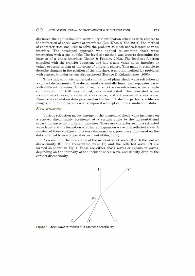
As a result of the interaction of the incident shock wave (I) with the contact
discontinuity (C), the transmitted wave (T) and the reflected wave (R) are
formed as shown in Fig. 1. These are either shock waves or expansion waves,
depending on the intensity of the incident shock wave and density drop at the
contact discontinuity.
Figure 1. Shock wave refraction at a contact discontinuity
9030 P. V. BULAT AND K. N. VOLKOV
The velocity of a transmitted shock wave depends on the ratio of densities
at a contact discontinuity σ = ρ2/ρ1. Hence, the velocity of a transmitted shock
wave is either higher (slow–fast refraction, S/F) or lower (fast–slow refraction,
F/S) than the velocity of an incident shock wave, depending on the ratio of
surfaces (Abd-El-Fattah & Henderson, 1978; Henderson, Colella & Puckett,
1991). Velocity qualifies as the acoustic impedance of media. Word order
determines the direction of wave propagation. In the slow–fast (S/F, σ > 1) case,
the reflected wave is an expansion wave, while in the fast–slow (F/S, σ < 1) case,
it is a shock wave. Each group (S/F and F/S) can be divided into a number of
additional configurations depending on the intensity of the incident shock wave
(Nouragliev, 2005). Previous researches observed 8 different refraction modes in
the S/F case and 4 different refraction modes in the F/S case by changing the
experimental conditions (Abd-El-Fattah & Henderson, 1978). The conditions for
the existence of each mode as well as the conditions for the transition from one
mode to another were also examined. The stability of the configurations was
examined (Fang, Wang & Yuan, 2011).
With respect to certain parameters, a transition takes place from regular
refraction (when three waves converge at a point) to non-regular refraction
(when a Mach stem is formed). Extant research provides a detailed description
and analysis of various modes of shock wave refraction at a contact discontinuity
(Henderson, 1989; Nouragliev et al., 2005).
Computational domain and boundary conditions
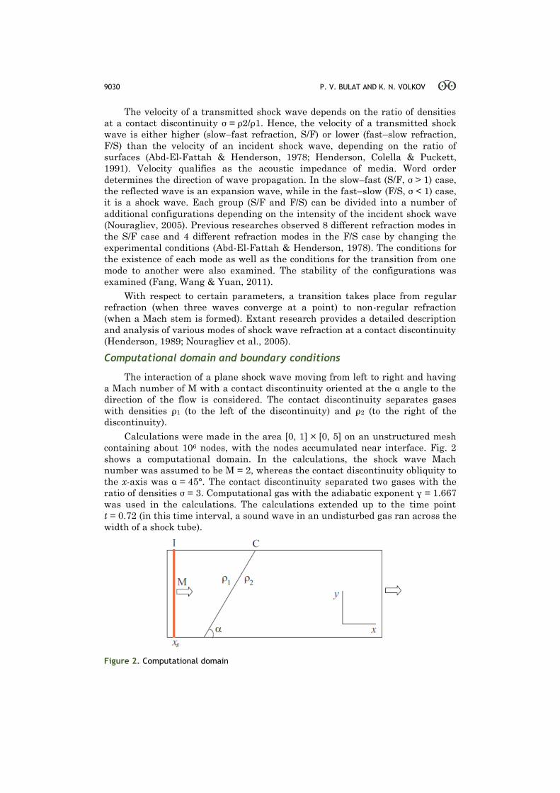
The interaction of a plane shock wave moving from left to right and having
a Mach number of M with a contact discontinuity oriented at the α angle to the
direction of the flow is considered. The contact discontinuity separates gases
with densities ρ1 (to the left of the discontinuity) and ρ2 (to the right of the
discontinuity).
Calculations were made in the area [0, 1] × [0, 5] on an unstructured mesh
containing about 106 nodes, with the nodes accumulated near interface. Fig. 2
shows a computational domain. In the calculations, the shock wave Mach
number was assumed to be M = 2, whereas the contact discontinuity obliquity to
the x-axis was α = 45°. The contact discontinuity separated two gases with the
ratio of densities σ = 3. Computational gas with the adiabatic exponent γ = 1.667
was used in the calculations. The calculations extended up to the time point
t = 0.72 (in this time interval, a sound wave in an undisturbed gas ran across the
width of a shock tube).
Figure 2. Computational domain
INTERNATIONAL JOURNAL OF ENVIRONMENTAL & SCIENCE EDUCATION 9031
At the initial time moment, gases separated by a contact discontinuity were
considered in a rest, and the shock wave front was located at xs = 0.1 (near the
left boundary of the computational domain). The Rankine–Hugoniot relations
were applied to the shock wave front. Non-reflecting boundary conditions were
applied to the inlet and outlet boundaries of the computational domain. At the
bottom boundary, symmetry conditions were applied (solid boundary).
The numerical method
The numerical model was constructed on the basis of the solution of the
unsteady Euler equations for inviscid compressible gas (Volkov, 2008).
The Euler equations were discretized by the finite volume method and an
explicit WENO scheme of third-order accuracy on an unstructured mesh.
Previous studies provide examples of the application of WENO schemes in the
simulation of supersonic flows of inviscid compressible gas on unstructured
meshes (Bulat & Volkov, 2015a; Bulat & Volkov, 2015b). Convective flows were
calculated independently for each direction using HLLC (Harten–Lax–van Leer–
Contact) Riemann solver. Time integration was performed using a third-order
Runge–Kutta method. A perfect gas equation of state with a constant ratio of
specific heat capacities was used.
Discontinuity identification
The process of gas-dynamic discontinuity identification (i.e., identification of
their type and position) involves considerable time and does not lack in
subjectivity. A method to accelerate the process and increase its accuracy was
proposed (Vorozhtsov, 1990). This involved calculating the density gradient and
its orientation in the center of each mesh cell. Points with a density gradient
above the average across the area were considered as points of discontinuity.
GDD were classified by examining the nearest points for discrete analogs of the
conditions observed at strong discontinuities. Eventually, each point belonged to
a certain type of discontinuity, namely shock wave (normal or oblique),
tangential discontinuity, contact discontinuity, or compression wave
(Vorozhtsov, 1990).
Numerical differentiation causes noise interference in the resulting image.
The order of accuracy of a finite difference scheme is decreased to the first-order
near the discontinuity. This is usually required to preserve the monotonicity of
the finite difference scheme. However, this also causes interference (Volkov,
2008). A smoothing operation was performed to eliminate the noise interference
(Schalkoff, 1988).
Contact discontinuity identification involves the application of the level-set
method. The level-set function complies with the transfer equation, and it has a
zero value at an interface or values opposite in sign at the areas of different
phases. This makes it possible to describe changes in the position of the
interface. The condition at the contact discontinuity ζ(t) = 0 makes it possible to
track its position in time (on the left and right side of the discontinuity. it is
assumed that ζ = ±1).
Results and Discussions
9032 P. V. BULAT AND K. N. VOLKOV
In the calculations, the obliquity angle of a contact discontinuity to the
horizontal is assumed to be α = 45°. With the given problem parameters, a
regular refraction mode was implemented, and a reflected shock wave was
formed R. Samtaney, 2003. A refraction mode wherein the reflected
discontinuity was an expansion wave was examined P. Delmont, R. Keppens &
B. van der Holst, 2009. The case when α = 90° corresponded to a one-
dimensional solution to the problem of shock wave interaction with a contact
discontinuity.
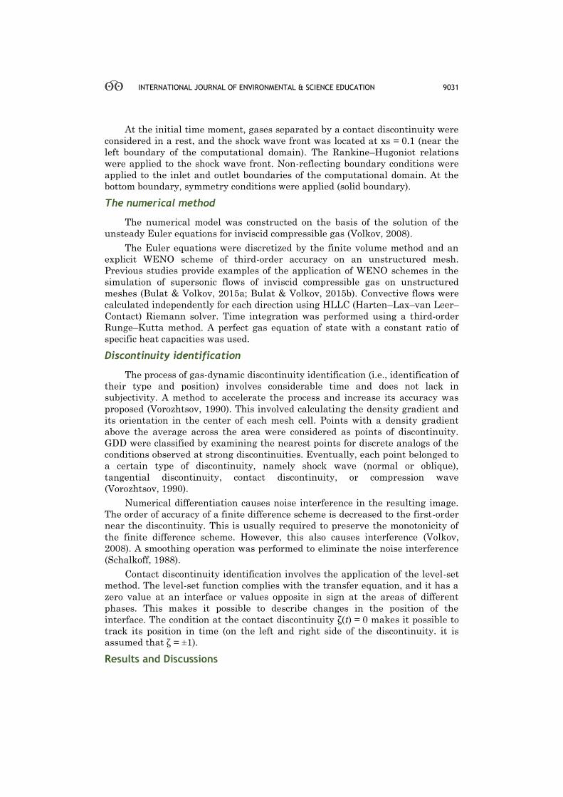
Fig. 3 shows the density contours at the time moment t = 0.72. Gas density
changes from 2.5 to 8.2. The density distribution shows the location of the
reflected shock wave and contact discontinuity.
Figure 3. Contours of density
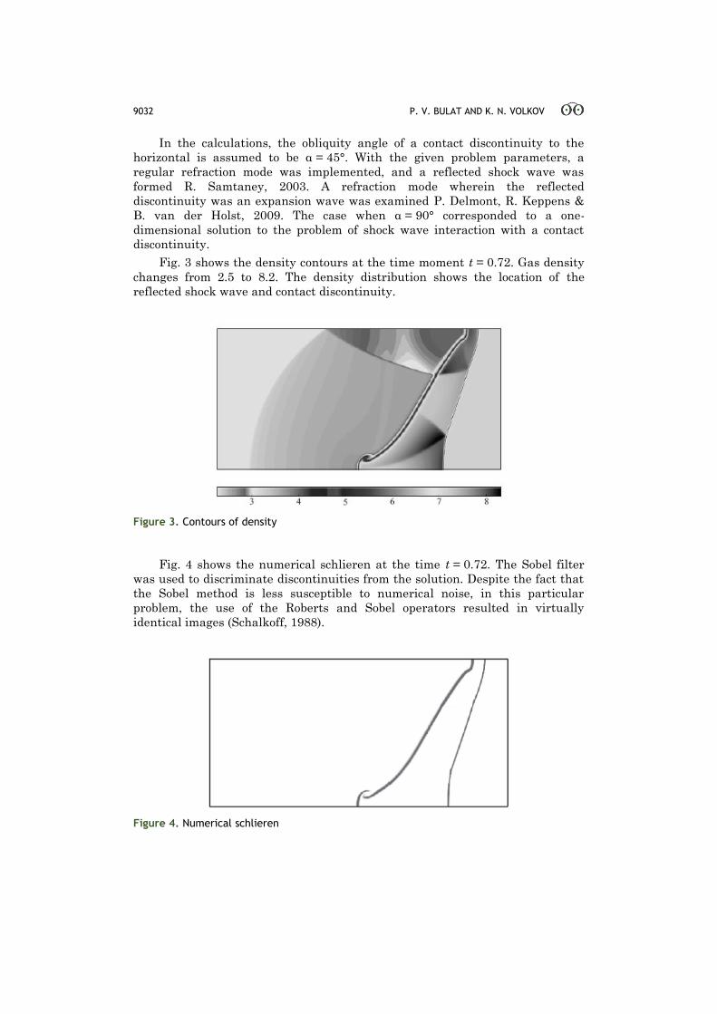
Fig. 4 shows the numerical schlieren at the time t = 0.72. The Sobel filter
was used to discriminate discontinuities from the solution. Despite the fact that
the Sobel method is less susceptible to numerical noise, in this particular
problem, the use of the Roberts and Sobel operators resulted in virtually
identical images (Schalkoff, 1988).
Figure 4. Numerical schlieren
INTERNATIONAL JOURNAL OF ENVIRONMENTAL & SCIENCE EDUCATION 9033
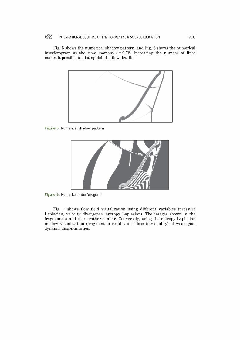
Fig. 5 shows the numerical shadow pattern, and Fig. 6 shows the numerical
interferogram at the time moment t = 0.72. Increasing the number of lines
makes it possible to distinguish the flow details.
Figure 5. Numerical shadow pattern
Figure 6. Numerical interferogram
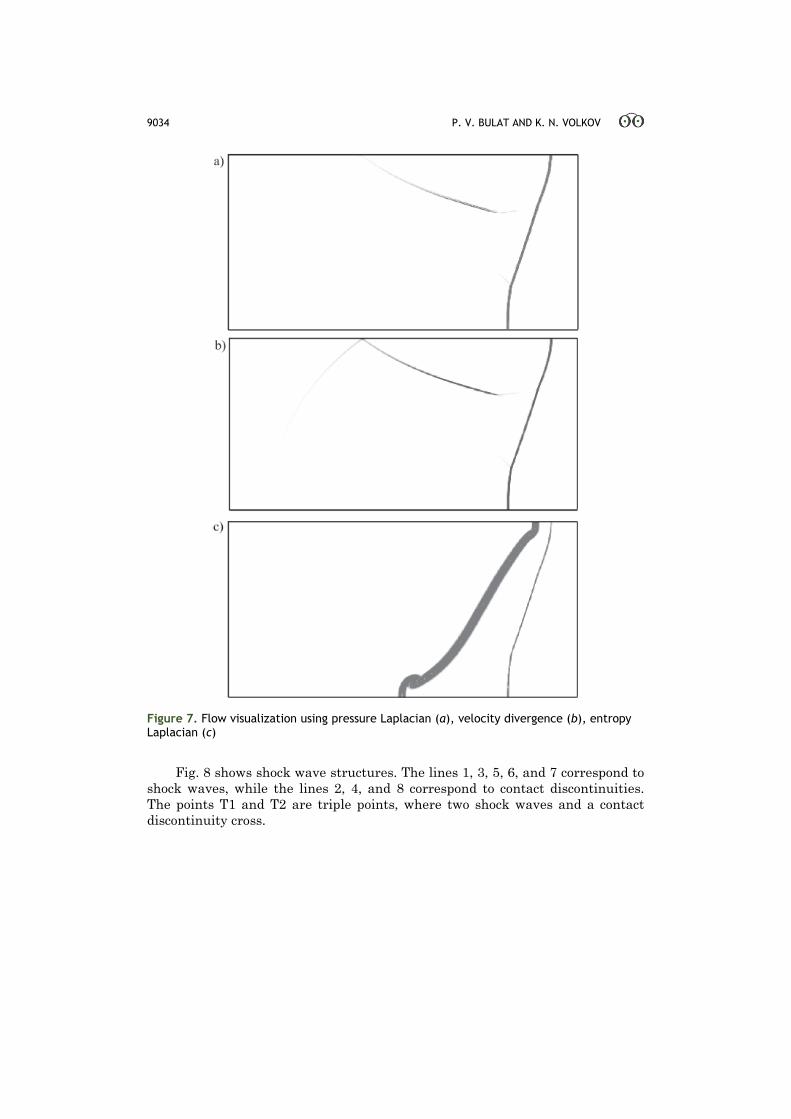
Fig. 7 shows flow field visualization using different variables (pressure
Laplacian, velocity divergence, entropy Laplacian). The images shown in the
fragments a and b are rather similar. Conversely, using the entropy Laplacian
in flow visualization (fragment c) results in a loss (invisibility) of weak gas-
dynamic discontinuities.
9034 P. V. BULAT AND K. N. VOLKOV
Figure 7. Flow visualization using pressure Laplacian (a), velocity divergence (b), entropy Laplacian (c)
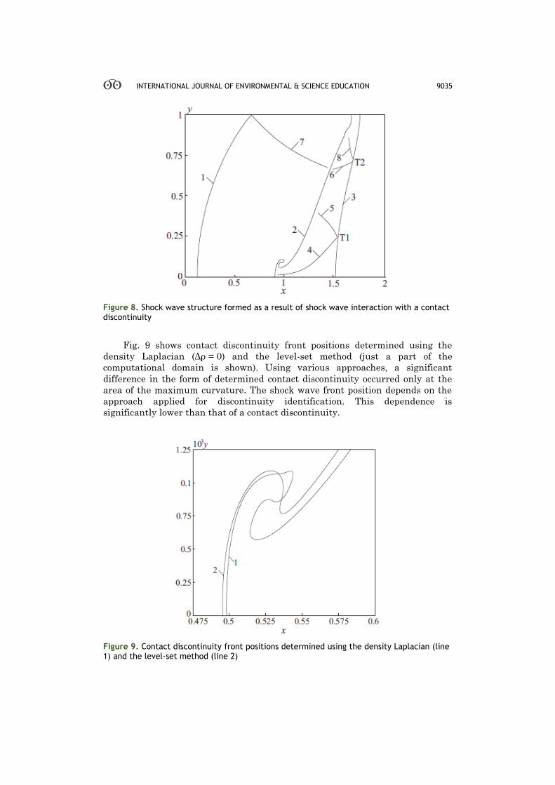
Fig. 8 shows shock wave structures. The lines 1, 3, 5, 6, and 7 correspond to
shock waves, while the lines 2, 4, and 8 correspond to contact discontinuities.
The points T1 and T2 are triple points, where two shock waves and a contact
discontinuity cross.
INTERNATIONAL JOURNAL OF ENVIRONMENTAL & SCIENCE EDUCATION 9035
Figure 8. Shock wave structure formed as a result of shock wave interaction with a contact discontinuity
Fig. 9 shows contact discontinuity front positions determined using the
density Laplacian (Δρ = 0) and the level-set method (just a part of the
computational domain is shown). Using various approaches, a significant
difference in the form of determined contact discontinuity occurred only at the
area of the maximum curvature. The shock wave front position depends on the
approach applied for discontinuity identification. This dependence is
significantly lower than that of a contact discontinuity.
Figure 9. Contact discontinuity front positions determined using the density Laplacian (line 1) and the level-set method (line 2)
9036 P. V. BULAT AND K. N. VOLKOV
Conclusion
The interaction of a shock wave with an interface separating two gases
produces a rich variety of flow phenomena even in the simplest configurations.
Numerical simulation of plane shock wave interaction with an inclined contact
discontinuity separating gases with different densities was performed. Results of
the numerical visualization of shock wave flow patterns were compared with the
data obtained from optical observations (including shadow patterns, schlieren
images, and interferograms). Digital image processing methods were used to
identify GDDs. The form of a contact discontinuity determined using the level-
set method was compared with that obtained using a density Laplacian.
The code developed could be used to investigate wave pattern in more
complex cases including transition from slow-fast to fast-slow refraction. The
experimental results show that after reflection from the top wall, the contact
discontinuity becomes unstable due to Kelvin–Helmholtz instability, causing it
to roll up and form a Richtmyer–Meshkov instability. These instabilities are
subject of intensive research and will be considered in future works. The
turbulent regime posed a significant challenge, and new experimental data are
required to generalize the time evolution of the interface over a wide range of
initial conditions.
Acknowledgements
The research was conducted with financial support from the Ministry of
Education and Science of the Russian Federation (agreement No.
14.575.21.0057), a unique identifier for Applied Scientific Research (project)
RFMEFI57514X0057.
Disclosure statement
No potential conflict of interest was reported by the authors.
Notes on contributors
Pavel V. Bulat - Head of International Laboratory of Mechanics and Energy
Systems, National Research University of Information Technologies, Mechanics and
Optics University ITMO, Saint Petersburg, Russian Federation.
Konstantin N. Volkov - Department of Mechanical and Automotive Engineering,
Senior lecturer, Kingston University, London, United Kingdom.
References
Abd-El-Fattah, A.M. & Henderson, L.F. (1978). Shock waves at a fast-slow gas interface. Journal of
Fluid Mechanics, 86, 15–32.
Banuti, D.T., Grabe, M. & Hannemann, K. (2011). Steady shock refraction in hypersonic ramp flow.
AIAA Paper, 2011-2215.
Brouillette, M. (2002). The Richtmyer–Meshkov instability. Annual Review of Fluid Mechanicsm 34,
445–468.
Bulat, P.V. & Uskov, V.N. (2014). Shock and detonation wave in terms of view of the theory of
interaction gasdynamic discontinuities. Life Science Journal, 11(8), 307–310.
Bulat, P.V. & Volkov, K.N. (2015a). Simulation of supersonic flow in a channel with a step on
nonstructured meshes with the use of the WENO scheme. Journal of Engineering Physics and
Thermophysics, 88(4), 848–855.
Bulat, P.V. & Volkov, K.N. (2015b). Using WENO schemes for simulation of reflected shock wave
with a boundary level. Journal of Engineering Physics and Thermophysics, 88(5), 1163–1170.
INTERNATIONAL JOURNAL OF ENVIRONMENTAL & SCIENCE EDUCATION 9037
Burago, N.G. & Kukudzhanov, V.N. (2005). A review of contact algorithms. The Institute for
Problems in Mechanics of RAS, 1, 45–87.
Delmont, P., Keppens, R. & van der Holst, B. (2009). An exact Riemann solver based solution for
regular shock refraction. Journal of Fluid Mechanics, 627, 33–53.
Dutta, S., Glimm, J., Grove, J.W., Sharp, D.H. & Zhang, Y. (2004). Error comparison in tracked and
untracked spherical simulations. Computers and Mathematics with Applications, 48(10-11),
1733–1747.
Fang, B., Wang, Y.G. & Yuan, H. (2011). Reflection and refraction of shocks on an interface with a
reflected rarefaction wave. Journal of Mathematical Physics, 52, 073702.
Henderson, L.F. (1989). On the refraction of shock waves. Journal of Fluid Mechanics, 198, 365–386
(1989).
Henderson, L.F., Colella, P. & Puckett, E.G. (1991). On the refraction of shock waves at a slow-fast
gas interface. Journal of Fluid Mechanics, 224, 1–27.
Jahn, R.G. (1956). The refraction of shock waves at a gaseous interface, Journal of Fluid Mechanics,
1, 457–489.
Liu, T.C., Khoo, B.C. & Yeo, K.S. (2001). The simulation of compressible multi-medium flow. I. A
new methodology with test applications to 1D gas–gas and gas–water cases. Computers and
Fluids, 30(3), 291–314.
Nouragliev, R.R., Sushchikh, S.Y., Dinh, T.N. & Theofanous, T.G. (2005). Shock wave refraction
patterns at interfaces. International Journal of Multiphase Flow, 31(9), 969–995.
Osher, S.J. & Fedkiw, R.P. (2003). Level set method and dynamic implicit surfaces, New York:
Springer, 352 p.
Pember, R.B. & Anderson, R.W. (2001). Comparison of direct Eulerian Godunov and Lagrange plus
remap, artificial viscosity schemes. AIAA Paper 2001-2644, 255-267.
Samtaney, R. (2003). Suppression of the Richtmyer–Meshkov instability in the presence of a
magnetic field. Physics of Fluids, 15, 53–56.
Samtaney, R. & Meiron, D.I. (1997). Hypervelocity Richtmyer–Meshkov instability. Physics of
Fluids, 9(6), 1783–1803.
Samtaney, R. & Pullin, D.I. (1996). On initial-value and self-similar solutions of the compressible
Euler equations. Physics of Fluids, 8(10), 2650–2655.
Samtaney, R. & Zabusky, N.J. (1993). On shock polar analysis and analytical expressions for
vorticity deposition in shock-accelerated density stratified interfaces. Physics of Fluids, 5(6),
285–1287.
Samtaney, R. & Zabusky, N. (2000). Visualization, extraction and quantification of discontinuities in
compressible flows. Techniques and Examples, 317-344.
Schalkoff, R.J. (1988). Digital image processing and computer vision. New York: John Wiley & Sons,
377 p.
Uskov, V.N., Bulat, P.V. & Arkhipova L.P. (2014a) Gas-dynamic discontinuity conception. Research
Journal of Applied Sciences, Engineering and Technology, 8(22), 2255–2259 (2014).
Uskov, V.N., Bulat, P.V. & Arkhipova, L.P. (2014b) Classification of gas-dynamic discontinuities and
their interference problems,” Research Journal of Applied Sciences, Engineering and
Technology, 8(22), 2248–2254.
Volkov, K.N. (2008). Unstructured-grid finite-volume discretization of the Navier-Stokes equations
based on high-resolution difference schemes. Computational Mathematics and Mathematical
Physics, 48(7), 1181-1202.
Vorozhtsov, E.V. (1990). On the classification of discontinuities by the pattern recognition methods.
Computers and Fluids, 18(1), 35-74.
Wheatley, V., Pullin, D.I. & Samtaney, R. (2005). Regular shock refraction at an oblique planar
density interface in magnetohydrodynamics, Journal of Fluid Mechanics, 522, 179–214.
Yang, X., Chern, I., Zabusky, N.J., Samtaney, R. & Hawley, J.F. (1992). Vorticity generation and
evolution in shock-accelerated density-stratified interfaces. Physics of Fluids, 4(7), 1531–1540.
Zeng, S. & Takayama, K. (1996). On the refraction of shock wave over a slow-fast gas interface. Acta
Astronautica, 38(11), 829–838.
9038 P. V. BULAT AND K. N. VOLKOV
Znamenskaya, I.A., Ivanov, I.E., Koroteyeva, E.Yu. & Orlov, D.M. (2011). Gas-dynamic phenomena
during shock wave interaction with the cooling plasma of impulse surface discharge. Reports of
the Russian Academy of Sciences, 439(5), 609–612.