Embed Size (px)
Citation preview

HAL Id: hal-00587976https://hal.archives-ouvertes.fr/hal-00587976
Submitted on 22 Apr 2011
HAL is a multi-disciplinary open accessarchive for the deposit and dissemination of sci-entific research documents, whether they are pub-lished or not. The documents may come fromteaching and research institutions in France orabroad, or from public or private research centers.
L’archive ouverte pluridisciplinaire HAL, estdestinée au dépôt et à la diffusion de documentsscientifiques de niveau recherche, publiés ou non,émanant des établissements d’enseignement et derecherche français ou étrangers, des laboratoirespublics ou privés.
Numerical studies of the combined effects of blast andfragment loading
Ulrika Nyström, Kent Gylltoft
To cite this version:Ulrika Nyström, Kent Gylltoft. Numerical studies of the combined effects of blast and frag-ment loading. International Journal of Impact Engineering, Elsevier, 2009, 36 (8), pp.995.�10.1016/j.ijimpeng.2009.02.008�. �hal-00587976�
Please cite this article as: Nyström U, Gylltoft K. Numerical studies of the combined effects of blast and fragment loading, International Journal of Impact Engineering (2009), doi: 10.1016/j.ijimpeng.2009.02.008
This is a PDF file of an unedited manuscript that has been accepted for publication. As a service to our customers we are providing this early version of the manuscript. The manuscript will undergo copyediting, typesetting, and review of the resulting proof before it is published in its final form. Please note that during the production process errors may be discovered which could affect the content, and all legal disclaimers that apply to the journal pertain.
Accepted Manuscript
Title: Numerical studies of the combined effects of blast and fragment loading
Authors: Ulrika Nyström, Kent Gylltoft
PII: S0734-743X(09)00052-9
DOI: 10.1016/j.ijimpeng.2009.02.008
Reference: IE 1757
To appear in: International Journal of Impact Engineering
Received Date: 22 July 2008
Revised Date: 20 February 2009
Accepted Date: 24 February 2009

TPIRCSUNAM DETPECCA
ARTICLE IN PRESS
Numerical studies of the combined effects of blast and fragment loading
Ulrika Nyström*, Kent Gylltoft
Department of Civil and Environmental Engineering, Structural Engineering, Concrete Structures,
Chalmers University of Technology, SE-412 96 Göteborg, Sweden
Abstract
The well-known synergetic effect of blast and fragment loading, observed in numerous experiments,
is often pointed out in design manuals for protective structures. However, since this synergetic effect is
not well understood it is often not taken into account, or is treated in a very simplified manner in the
design process itself. A numerical-simulation tool has been used to further study the combined blast and
fragment loading effects on a reinforced concrete wall. Simulations of the response of a wall strip
subjected to blast loading, fragment loading, and combined blast and fragment loading were conducted
and the results were compared. Most damage caused by the impact of fragments occurred within the first
0.2 ms after fragments’ arrival, and in the case of fragment loading (both alone and combined with blast)
the number of flexural cracks formed was larger than in the case of blast loading alone. The overall
damage of the wall strip subjected to combined loading was more severe than if adding the damages
caused by blast and fragment loading treated separately, which also indicates the synergetic effect of the
combined loading.
Key-words: Numerical simulation, Blast load, Fragment impact, Combined loading, Concrete
1 Introduction
The combined loading of blast and fragments, caused by explosions, is considered to be synergetic in
the sense that the combined loading results in damage greater than the sum of damage caused by the blast
TPIRCSUNAM DETPECCA
ARTICLE IN PRESS
and fragment loading treated separately, [1]. This is a well-known phenomenon pointed out in some of
the literature and design manuals within the area of protective design [2]. However, due to the complex
nature of the effect of combined loading, its high parameter dependence and the limited number of
documentations and comparable experiments, the design manuals often disregard the effect or treat it in a
very simplified manner.
In order to increase the understanding of the combined effects of blast and fragment loading,
numerical simulations were conducted. The simulations consist of a wall strip subjected to blast and
fragment loading, applied both separately and simultaneously. To be able to draw general conclusions
about the effect of combined loading the complexities of the structure and the applied loads was reduced.
The cases studied in this paper are purely academic, where both the structure and the loads are based on a
“real case”, i.e. requirements of protective capacity stated in the Swedish Shelter Regulations [3], but are
strictly idealized in order to give useful results from which conclusions can be drawn. Using a numerical-
simulation tool is motivated by e.g. the high cost of undertaking tests, and the possibility to better follow
and understand the principal phenomena related to this kind of loading.
This work is a substudy within a project with the long-term aim to study and increase the knowledge
of blast and fragment impacts, and the synergy effect of these loads, on reinforced concrete structures.
The research project is a collaboration of many years’ duration between Chalmers University of
Technology and the Swedish Rescue Services Agency. In earlier studies within the framework of this
project, the effect of blast waves in reinforced concrete structures, fragment impacts on plain concrete,
and design with regard to explosions and concrete, reinforced and fibre-reinforced, subjected to projectile
impact were studied by Johansson [4], Leppänen [5] and Nyström [6,7], respectively.
2 Theoretical framework
2.1 Weapon load characteristics
As detonation of the explosive filler in a cased bomb is initiated, the inside temperature and pressure
will increase rapidly and the casing will expand until it breaks up in fragments. The energy remaining
after swelling and fragmenting the casing, and imparting velocity to the fragments, expands into the
surrounding air and thus creates a blast wave. Thereby, the structures around a bomb detonation will be
TPIRCSUNAM DETPECCA
ARTICLE IN PRESS
exposed to both blast and fragment loading, which means that at least three types of loading effects must
be considered:
• impulse load from blast wave
• impulse load from striking fragments
• impact load from striking fragments
where impulse is considered to give a global response and impact a local response caused by the
penetration of the fragments.
There are many different types of weapons, designed to have a specific effect on the surroundings. In
design of protective structures a threat-determination methodology, based on probability aspects, must be
used to decide what load conditions the structure is to be designed for. There are methodologies for
calculating the characteristics of the blast and fragment loads caused by explosion, which are well
accepted in the design of protective structures. However, even though the blast load characteristics for a
bare high-explosive detonation can be estimated with great accuracy, the loads from a cased bomb cannot
be determined as accurately [2]. Due to the complexity of not only the blast itself but also the
fragmentation of the casing, these load estimations are more uncertain.
Since the properties of the bomb (geometry, casing material and thickness, type of explosive filler,
etc.) and its position relative to the target, as well as the surrounding environment, have influence on the
loading conditions, all these parameters must be considered during analysis of the loading effect. Also the
distance from the detonation (stand-off) will greatly influence the loading properties. This is mainly due
to the change in peak pressure for the blast wave and the change in velocity of the fragments, which both
decrease with increasing distance. The retardation of the blast wave is larger than that of the fragments,
leading to a difference in arrival time. In the range closest to the bomb, i.e. within a few metres, the blast
wave will reach the target before the fragments, while at larger distances the fragments will arrive before
the blast wave. For a 250 kg general-purpose bomb (GP-bomb), with 50 weight per cent TNT, the blast
front and the fragments will strike the target at the same time at an approximate distance of 5 metres;
according to Fig. 1, where the time of arrival of the blast load and the fragments are calculated by means
of ConWep [8] (based on equations of Kingery and Bulmash [9]) and Janzon [10], respectively.
TPIRCSUNAM DETPECCA
ARTICLE IN PRESS
2.1.1 Blast loading
The blast load resulting from a detonation of an uncased charge in "free air", i.e. distant from the
nearest reflecting surface, is well known and often idealised as shown in Fig. 2. The detonation takes
place at time t = 0 and arrives at the point studied at time ta. As the blast wave arrives, the pressure
increases from the ambient pressure, P0, to P0+Ps+, where Ps
+ is the incident overpressure caused by the
detonation. As time goes on, the overpressure decays and at time T+ after the time of arrival the pressure
is again equal to the ambient pressure P0 and the positive phase is over. Due to a partial vacuum formed
behind the blast front [11] a negative pressure Ps- (relative to the ambient pressure) appears and the
negative phase is entered. The duration of the negative phase is longer than the positive phase, but the
amplitude of the negative pressure is limited by the ambient pressure, P0, and is often small compared to
the peak overpressure, Ps+. However, in design with regard to explosions the negative phase is considered
less important than the positive phase and is therefore often disregarded.
As the blast wave strikes a surface, e.g. a wall, it is reflected and its behaviour changes. The so-called
normal reflection, taking place as the blast wave is reflected against a perpendicular surface, may lead to
significantly enhanced pressures, where the reflected peak overpressure Pr+ will be between 2 and 8 [2],
and according to [11,12] as much as 20, times higher than the incident overpressure Ps+. According to
[13] the shape of the reflected pressure has the same general shape as the incident pressure, as shown in
Fig. 3.
For cased charges the blast load characteristics depend not only on the type and amount of explosive
and the stand-off distance, but also on the properties (geometrical and material) of the casing. Since there
is less knowledge about how the casing affects the blast wave, there are also less generic expressions
describing this. In [14] an expression for calculating an equivalent uncased charge weight is given as a
function of the ratio between the casing weight and the actual charge weight. However, the reduced blast
pressure due to the energy consumed during casing break-up is often not taken into account in the design
manuals [2], which also is used in this study.
2.1.2 Fragment loading
As mentioned earlier, the casing of a bomb will swell after initiation of the explosive filler due to the
high pressure. During swelling, cracks will form and propagate in the casing; and as the cracks meet or
TPIRCSUNAM DETPECCA
ARTICLE IN PRESS
reach a free border, fragments are formed [15]. The nose and the tail section of the bomb will break up in
a smaller number of massive fragments and the body will fracture into many small fragments.
Derivation of theoretical expressions describing the fragmentation process and its characteristics for
cased bombs is difficult. This is partly due to the complexity of the phenomenon itself and partly due to
the great variation of bomb properties, which highly influences the fragmentation process. However,
there are expressions for estimating the mass distribution and velocities of the fragments that are based on
theoretical considerations and confirmed with a large number of tests [16]. In the derivation of these
expressions, the bomb casing is normally idealised as a cylinder with evenly distributed explosives,
meaning that the methods apply especially to items that can reasonably be approximated as either
cylindrical items or as a series of cylindrical items [16]. The more an item deviates from this ideal, the
less reliable are the estimations made using these methodologies.
In order to estimate the fragment mass distribution, a relationship developed by Mott [17,18]
(presented in e.g. [16,19]) is often used. For design purposes a design fragment is used. The mass of the
design fragment is often determined by specifying a confidence level giving the probability that the
weight of the fragment is the largest fragment produced. However, this method of determining the design
fragment is justified in design where the damage caused by the individual fragments is of interest as the
hazardous case. In the case of design against the fragment cluster, another approach may be more
desirable where the combined effect of the fragment impact and impulse is of interest. This is discussed
further in Section 4.2.
The initial velocity of the fragments can be estimated from the Gurney equation [20] (presented in e.g.
[16,19]), which also derives from an assumption of a cylindrical casing. Since this equation is based on
energy balance within the explosive and metal case system, without taking into account the loss of energy
during rupture of the casing, it is an upper bound estimation.
As the fragments travel through the air their velocity will decrease due to the drag forces. Smaller,
lighter fragments will retard faster than larger, heavier fragments. Equations describing this behaviour
exist as well, e.g. [16,19].
TPIRCSUNAM DETPECCA
ARTICLE IN PRESS
2.2 Concrete behaviour under static and dynamic loading
It is well known that the two most pronounced disadvantages of concrete are its low tensile strength
and brittle behaviour. The tensile strength of normal-strength concrete is less than one tenth of the
compressive strength, and after fracture initiation, i.e. after the tensile strength is reached, the ability to
transfer stresses through the material decreases rapidly. For high-strength concrete the brittle behaviour
can also be seen in the case of uni-axial compression, but the post-fracture ductility in compression
increases, with a decreasing compressive strength.
In multi-axial loading conditions the behaviour of concrete differs from the behaviour under uni-axial
loading. The ductility, stiffness and strength in compression increase with increased confinement, and for
very high lateral pressures the compressive strength may be more than 15 times higher than the uni-axial
compressive strength [5]. Such high lateral pressures may occur during impact and perforation of e.g.
projectiles and fragments.
High dynamic loading, giving a high strain rate in the material, also affects the strength and ductility
of the concrete. In the case of high-rate tensile loading, the ultimate uni-axial tensile strength may be as
much as 5 to 7 times higher than the static tensile strength [21], and even though the effect on the ultimate
compressive strength is less pronounced it may still be more than doubled [22]. It has recently also been
indicated that the fracture energy is strain-rate-dependent [23-25].
3 Method
Tests have been conducted around the world to study the combined effects of blast and fragment
loading, but these are often not suitable for drawing general conclusions about the local or global
structural behaviour. This is due to the great variation of parameters involved, e.g. load characteristics
and stand-off, which affects the results. Numerical simulations are often used to investigate the effect of
blast and fragments, and make it possible to study the influence of different parameters – stand-off
distance, fragment size, materials etc. – which is costly in experimental testing. Nevertheless, the
numerical simulations cannot fully supersede experiments, but should be used in combination, and
experiments are needed to verify the numerical models used in the simulations.
TPIRCSUNAM DETPECCA
ARTICLE IN PRESS
The reinforced concrete structure used in the study presented here are based on a wall strip in a civil
defence shelter, fulfilling the requirements of protective capacity related to conventional bombs in the
Swedish Shelter Regulations [3]. The loads applied, i.e. the blast wave and fragment loading, are also
based on the load definitions in [3].
As no suitable experiments, with combined blast and fragment loading, were found for this study,
two separate experiments on blast load and single fragment impact were used to verify and calibrate the
numerical model. The validation and calibration process was done within a preliminary study and is only
briefly described in this paper. Conclusions from the preliminary study were used to build up the
numerical model of the wall strip subjected to blast and fragment impacts used in the main study. Single-
degree-of-freedom analyses were used to find what load combination caused the largest deflection:
simultaneous arrival of the two loads, blast load arriving first, or fragments arriving first. The results from
the SDOF analyses were used to decide the arrival times for the loads in the numerical simulation of
combined loading. The numerical results of the wall-strip response were compared and analysed in order
to see the effects of combined loading.
For further information about this study the reader is referred to [26] where a detailed description of
the load characterisation and the preliminary study is presented.
4 Wall element and load characteristics
The Swedish Shelter Regulations [3] govern the design of civil defence shelters in Sweden, and
contain the requirements specified for these protective structures. Here only the criteria for protective
capacity related to conventional bombs are specified, but it should be pointed out that civil defence
shelters also are designed to withstand e.g. radioactive radiation, chemical and biological warfare, and
explosive gases.
According to [3], a civil defence shelter should be designed to withstand the effect of a pressure wave
corresponding to that produced by a 250 kg GP-bomb with 50 weight per cent TNT, which bursts freely
outside at a distance of 5.0 metres from the shelter during free pressure release. Further, the shelter must
also be able to withstand the effect of fragments from a burst as described above. In the case of fragment
TPIRCSUNAM DETPECCA
ARTICLE IN PRESS
loading it is the fragment cluster that is meant, while larger individual fragments may damage and
penetrate the shelter.
4.1 Wall element
In the Swedish Shelter Regulations [3], the civil defence shelter is conceived as a reinforced, solid
concrete structure. For a shelter without backfilling the minimum thicknesses of the roof, walls and floor
are specified as 350, 350 and 200 mm, respectively, and the concrete should fulfil a requirement of at
least C25/30, according to [27] (corresponds to mean cylindrical compressive strength of 25 MPa). Hot-
rolled reinforcement bars with a specified requirement of strain hardening must be used. The
reinforcement must be placed in two perpendicular alignments in both edges of the structural element and
the minimum and maximum reinforcement content is 0.14 and 1.10%, respectively. A minimum
reinforcement-bar diameter of 10 mm and maximum bar spacing of 200 mm are required, with a
maximum concrete cover of 50 mm.
The wall studied has a total height of 3 metres and is simplified to be simply supported with a span
length of 2.7 m, as seen in Fig. 4. The rough simplification of the support conditions was not made in an
attempt to imitate the real behaviour of the wall.
In [3], equivalent static loads, representing the weapon effect, are used in the design process. A
static load of 50 kN/m2 is used to calculate the required amount of reinforcement in the walls, giving
reinforcement bars ø10 s170 (465 mm2/m in each face of the wall element). Deformed reinforcement bars
(B500BT), with a yield strength of 500 MPa were assumed and the distance from concrete edge to centre
of reinforcement bars was chosen as 35 mm. The concrete was assumed to have a concrete strength of
35 MPa.
4.2 Load characteristics
In Fig. 5 the blast load caused by the GP-bomb specified in Section 4 with a stand-off of 5.0 metres,
calculated with ConWep [8], is shown together with a simplified relationship. It should be kept in mind
that design codes do often not take into account the energy consumed for swelling and fragmenting the
TPIRCSUNAM DETPECCA
ARTICLE IN PRESS
casing of bombs. As an approximation this energy loss is also neglected in the present study even though
it would be more accurate to reduce the pressure of the blast load in order to imitate the real behaviour.
The blast load is assumed to be uniform over the wall, which is reasonably accurate for this stand-off [4].
The impulse density of the blast load is, according to [8], 2 795 Ns/m2.
Since the geometry and casing material of the bomb used in the design of civil defence shelters are not
specified, the size and mass distribution cannot be calculated without making certain assumptions. In this
study, the American GP-bomb Mk82 was used as a reference when estimating the mass distribution of the
bomb specified in the Swedish Shelter Regulations. According to ConWep [8] the Mk82 has a nominal
weight of 500 lb (226.8 kg) and contains 192.0 lb (87.09 kg) of the high explosive H-6, corresponding to
242.9 lb (110.2 kg) equivalent weight of TNT, and is therefore relatively close to the bomb specified in
the Swedish Shelter Regulations [3]. The mass distribution was estimated by scaling the inner casing
diameter and the casing thickness to correspond to the somewhat increased volume of explosive filler
compared to the Mk82; for more details see [26].
All fragments used in the simulations were assumed to be spherical and of the same size,
corresponding to a design fragment. It was further assumed that the fragments were uniformly distributed
over the wall. Even though these idealizations are rough and differ from the real fragment loading caused
by a bomb, where the mass, shape and velocity of the fragments differs and the distribution of the
fragments over the wall is not uniform, they were necessary in order to reduce the complexity of both the
numerical model and the results produced. It can be pointed out that a more realistic fragment mass
distribution would give a more non-uniform damage over the wall, where the larger fragments would give
a larger local damage than the smaller fragments.
As mentioned in Section 2.1.2, the design fragment, calculated with a confidence level (often taken as
95%), is used for design with regard to fragment impact. However, this design fragment and the
corresponding effect on the target are not representative of the fragment impulse load which is important
to capture the global response caused by the fragments and not only their local effect. This means that
another approach must be used to find a representative fragment size in this study and it was decided to
use the impulse caused by the real fragment load on the wall, caused by a vertically placed bomb, to
define a representative weight of the fragments. From estimations of the mass and velocity distribution
among the fragments, the corresponding fragment impulse distribution was calculated, and a
TPIRCSUNAM DETPECCA
ARTICLE IN PRESS
representative fragment size was determined as the fragment mass giving the average impulse on the
structure, for details see [26]. This resulted in a fragment mass of 21.9 g and a fragment diameter of 17.5
mm. The initial fragment velocity was calculated to approximately 1 890 m/s (by use of the Gurney
equation), and at the distance of 5.0 metres the velocity is decreased to 1 760 m/s. The fragment density is
approximately 0.65 kg/m2 and the corresponding impulse intensity caused by the fragments is
1 125 Ns/m2.
4.3 SDOF estimations
The single-degree-of-freedom method (SDOF method) was used in order to find what combination
of arrival times of the blast and fragment load that resulted in the maximum deflection. The simplified
relation of the blast load, presented in Section 4.2, was used for the blast load and a triangular load was
assumed for the fragment loading. The duration of the fragment loading was assumed to 0.1 ms, which is
the approximate time it takes for the fragment to penetrate the concrete, and its impulse intensity was as
defined in Section 4.2, giving a peak pressure of 22.5 MPa. It should be pointed out that only the impulse
load of the fragments was taken into consideration in the SDOF analyses presented in this paper, since the
penetration by the fragments and the subsequent damage were not considered. An ideal-plastic material
response of the SDOF system was used and the maximum value of the internal dynamic resistance Rm of
the wall strip was calculated to be 275 kN; for details see Appendix A and [26].
In Fig. 6 the results are shown for five different cases of combined loading:
1. loads arrive at the same time (simultaneous loading)
2. blast wave first, fragments arrive at maximum wall velocity caused by the blast
3. blast wave first, fragments arrive at maximum wall deflection caused by the blast
4. fragments first, blast wave arrives at maximum wall velocity caused by the fragments
5. fragments first, blast wave arrives at maximum wall deflection caused by the fragments
As seen, the case of simultaneous loading causes the most severe deflection (equalling 139.2 mm at time
42.2 ms). For further information about the SDOF method the reader is referred to [6] and [19].
TPIRCSUNAM DETPECCA
ARTICLE IN PRESS
5 Numerical model
Hydrocodes are used for highly time-dependent dynamic problem-solving by use of finite difference,
finite volume and finite element techniques. The differential equations for conservation of mass,
momentum and energy, together with material models, describing the behaviour of the materials
involved, and a set of boundary conditions give the solution of the problem. The numerical hydrocode
AUTODYN 2D and 3D [28] was used in this study, and the Lagrangian solver technique was employed.
5.1 Calibration and validation of numerical model
Experiments and findings from numerical simulations of experiments described in the literature were
used in the calibration and validation process for the numerical model used in this study. The numerical
simulations for the calibration process were performed in 2D and 3D. The use of 2D was to prefer since it
reduces the computational time, but since beam elements (used to simulate the reinforcing bars) could not
be used in the 2D simulations, 3D was used when reinforced concrete were simulated. However, 3D was
used with the width of one element and use of boundary conditions to emulate a 2D simulation. Below is
a brief summary of the calibration and validation process; for further description see [26].
Magnusson and Hansson [29] described experiments on reinforced concrete beams, of length 1.72 m,
subjected to blast loading, and thereafter used AUTODYN 3D to simulate the beam response. They
concluded that it was possible to simulate the beam response with the RHT material model provided that
the principal-stress tensile-failure model with a fully associated flow rule (i.e. the flow rule was
associated in both the deviatoric and meridian planes) was used in the simulations, together with crack
softening. This was also found by means of numerical simulations of the same experiment conducted
within the calibration process made in the study presented here. In this process it was also found that an
element length of 12 mm gave approximately the same beam response as a finer mesh of 6-mm elements;
hence, the coarser mesh of 12-mm elements should be accurate enough to simulate the beam response
when subjected to blast loading.
Leppänen [30] performed and described experiments with a single fragment impacting a concrete
block, with size 750 x 350 x 500 mm. An AUTODYN 2D model with axial symmetry and different
element sizes (1 and 2 mm) was used in the calibration process, and it was concluded that the numerical

TPIRCSUNAM DETPECCA
ARTICLE IN PRESS
model gave accurate results. However, the size of the fragment used in [30] differed from the fragment
size used in this study, and hence, additional 2D simulations were conducted to investigate the effect of
the element size. It was concluded that the resulting crater in the simulations with an element size of
6 mm was somewhat different from the crater in simulations where smaller elements were used, but still
an acceptable approximation of the damage caused by the fragment impact. Thus, it was not considered
worth the greatly increased computational time to use a finer mesh in the main study.
5.2 Material models
The standard material model for concrete with compressive strength of 35 MPa in the material library
of AUTODYN was used to describe the behaviour of concrete. This material model was developed by
Riedel, Hiermayer and Thoma (therefore called the RHT model) [31], and consists of three pressure-
dependent surfaces in the stress space. The RHT model also takes into account pressure hardening, strain
hardening and strain-rate hardening as well as the third invariance in the deviatoric plane. However, the
preliminary study, i.e. the calibration and validation process described in Section 5.1, showed that it was
necessary to make some modifications within the model to get accurate results. For example, it was
concluded that a principal-stress tensile-failure model was necessary to describe the behaviour of the wall
strip in the case of blast loading, instead of the hydrodynamic tensile-failure model used as default in the
RHT model. The change to a principal-stress tensile-failure model leads to a cut-off of the strain-rate
dependence of the ultimate tensile strength.
To describe the behaviour of the reinforcing steel, a piecewise linear Johnson-Cook material model
was used, including strain hardening but not strain-rate and thermal effects. A linear elastic steel material
model, with a shear modulus of 81.1 GPa, was used for the supports, and a von Mises material model,
simplifying the material behaviour to linear-elastic–ideal-plastic with yield strength of 800 MPa, was
used for the fragments. A linear equation of state (EOS) was used for the reinforcing steel, the supports
and the fragments, while the nonlinear P-α EOS was used for the concrete. The input in the different
material models used in the simulations are presented in Tables 1 to 3; for further information about the
material models used, the reader is referred to [26,31,32].
TPIRCSUNAM DETPECCA
ARTICLE IN PRESS
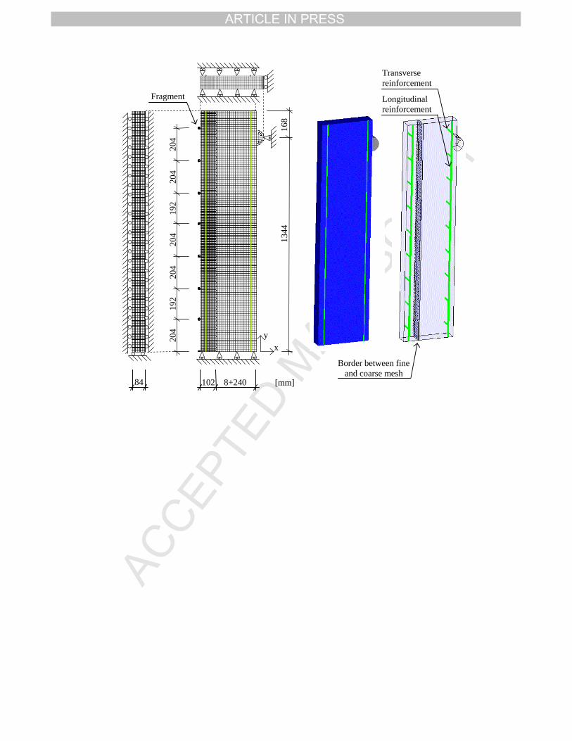
5.3 Mesh
Since fragment penetration is a local effect, requiring relatively small elements, a numerical model of
even a 1.0-metre wide strip of the shelter wall would have been very large and required extensive
computational time. By use of symmetries and plane-strain-boundary conditions the model was limited to
a 84 x 1 512 x 350 mm part of the wall, representing 4.25% of a metre-wide wall strip which reduces the
total number of elements used in the model from approximately 2.3 million to 98 106. Even though the
width of the wall strip is only 9.6 times the fragment dimension and the size of the front face crater
caused by the fragment impact (measured in the 2D simulations used for calibration described in
Section 5.1) approximates the width of the wall strip included in the model the use of plane-strain-
boundary conditions are applicable. The plane-strain-boundary condition takes into account the next row
of fragments which strikes the wall 168 mm from the row of fragments included in the model. Including a
wider part of the wall in the model, where the choice of width of course has to be done with respect to the
loading case, would only lead to negligible changes in the results.
Due to the varying need of element sizes when simulating the effects of blast and fragment impact, a
finer mesh of Lagrangian elements (size 6 x 6 x 6 mm) was used on the front face of the wall strip, and a
coarser mesh of elements (size 12 x 12 x 6 mm) of the same element type was used on the rear side of the
wall strip (see Fig. 7), resulting in a total number of 97 020 concrete elements, where 59 976 of those
were in the front zone where the finer mesh was used and 37 044 in the rear zone with the coarser mesh.
The total number of elements along the depth (x-direction), the height (y-direction) in the front- and rear-
zones, and the width (z-direction) of the concrete structure included in the model were, 38, 252, 126 and
14, respectively.
The wall strip was supported by two semicylindrical supports with a radius of 84 mm to avoid local
crushing of the elements around the supports. The nodes of the support were joined together with the
interfacing concrete nodes. In order to allow for rotation around the supports only the line of back nodes
was prevented from moving in the x-direction. The supports were modelled with 4 elements along the
radius of the half-cylinders, resulting in a total number of 336 elements in one support.
In the simulations including impacting fragments, these were modelled with two elements along their
radius, resulting in 16 elements per half-fragment and a total number of 120 fragment elements in the
model. Embedded beam elements with the same length as the surrounding concrete elements and with
TPIRCSUNAM DETPECCA
ARTICLE IN PRESS
circular cross-section were used to model the reinforcement bars, giving a total number of 630 beam
elements in the model.
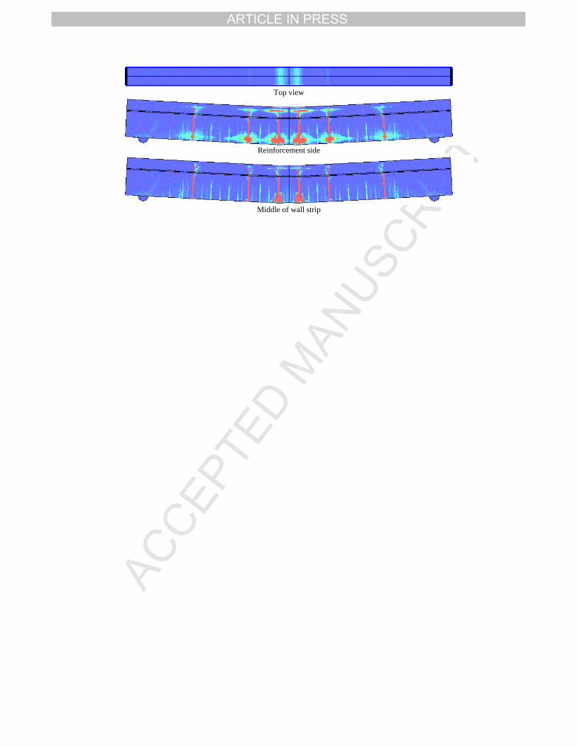
6 Results
The responses of the wall strip estimated in the numerical simulations for blast loading, fragment
loading, and combined blast and fragment loading (simultaneous loading) are presented and discussed
below. As the damage differs at different locations within the wall strip, the damage is shown in three
views for each case: a top view, a side view at the section of reinforcement, and one in the middle of the
wall strip (the section where the fragments strike the wall strip). In the figures with the wall strip
responses, the colour red indicates fully damaged concrete.
6.1 Blast loading
In the case of blast loading, the maximum deflection is 65.2 mm and takes place 29.0 ms after the
arrival. In Fig. 8 the damage in the wall strip is shown at time of maximum deflection, where it can be
seen that cracks have formed at the rear side of the wall strip and have propagated towards the front face.
The damage is localised to relatively few cracks, even though it can be seen that crack initiation has taken
place rather densely along the length of the strip. Damaged concrete can also be seen along the
reinforcement close to the fully developed cracks; at these locations the reinforcement bars were yielding.
When studying the crack development, it was seen that the localised crack closest to the support was
formed already after 1 ms, while no damage of the concrete was observed in the middle of the beam at
this time. This indicates a direct shear crack due to the inertia effects, i.e. internal momentum, related to
severe dynamic loading. After approximately 2 ms, also the localised cracks in the middle of the beam
have formed, and these have the character of flexural cracks.
TPIRCSUNAM DETPECCA
ARTICLE IN PRESS
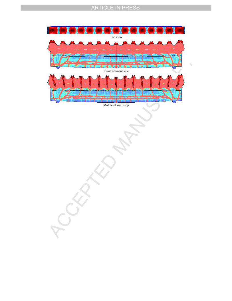
6.2 Fragment loading
In Fig. 9 the wall strip subjected to fragment loading is shown at time of maximum deflection. This is
reached 13.3 ms after the fragments strike the wall, and amounts to 11.0 mm. As can be seen, the
simulated damage caused by the multi-fragment impact is more complex than in the case of blast loading.
The total damage consists of local damage on the front face, i.e. craters, scabbing cracks at the rear of the
wall strip, direct shear cracks close to the supports, and bending cracks in the more central parts of the
beam. When comparing Fig. 8 and Fig. 9, it can be seen that there are more bending cracks formed in the
case of fragment impact than for blast loading, resulting in an increased energy-absorbing capacity since
the reinforcement bars can yield at more locations. This means that also the load-bearing capacity may
increase. However, the load-bearing capacity will at the same time be reduced by the decreased effective
height due to the damage on the front face of the wall strip.
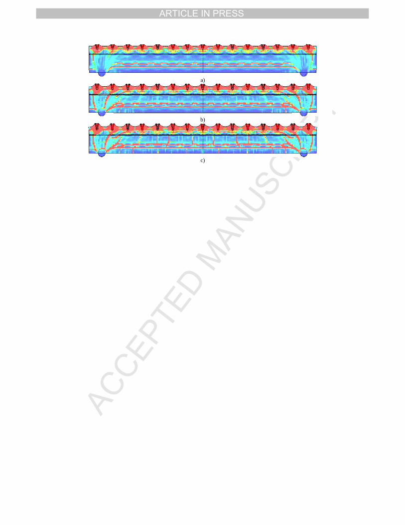
To better distinguish the modes of damage and to better understand their evolution, the beam response
is shown at different times, i.e. after 0.25, 0.6 and 9 ms, in Fig. 10. After 0.25 ms (Fig. 10a) the fragment
impacts have caused craters on the front face, and the reflected stress wave has caused scabbing cracks at
the rear of the wall strip. The scabbing effect was not expected in the simulations, but 2D simulations of
fragment impact, taking the multiple simultaneous impact of fragments and also the strain-rate
dependence of the tensile strength into account, confirm this behaviour; see [26]. However, in reality the
two scabbing cracks probably represent one crack which appears at the level of tensile reinforcement and
not in between the two reinforcement layers, as in this case.
Approximately 0.6 ms after the arrival of fragments, cracks propagate at the rear side of the wall strip,
close to the supports, see Fig. 10b. These are probably direct shear cracks, as also observed in blast
loading; see Section 6.1.
At time 9 ms, flexural cracks have started to propagate in the wall strip, as seen in Fig. 10c. These
cracks form at the rear face of the target, but also at the level of the scabbing cracks, which indicates that
the wall strip has started to act as two separate structures with sliding between the two separate planes
formed by the horizontal scabbing cracks.
TPIRCSUNAM DETPECCA
ARTICLE IN PRESS
6.3 Combination of blast and fragment loading
The maximum mid-point deflection in case of simultaneous loading of blast and fragment is 85.7 mm
and occurs after 33.4 ms. The response of the wall strip at time of maximum deflection is shown in
Fig. 11. As the damage caused by the fragment impact, i.e. the front face craters and the scabbing cracks
at the rear of the strip, appears very early (at less than 0.25 ms, as seen in Section 6.2) the damage in the
case of combined, simultaneous loading is rather similar to the case of fragment loading alone. Due to the
blast load, the deflection is larger and the damage in the concrete surrounding the reinforcement bars is
more severe than in the case of fragment impact alone.
Further, the diameters of the front face craters are reduced in case of combined loading compared to
fragment loading alone. This can probably be explained by increased confinement effects. The blast wave
causes pressure on the front face, acting perpendicular to the concrete surface, and gives a lateral pressure
to the material compressed by the fragment penetration; schematically shown in Fig. 12. This reduction of
front-face damage may lead to a higher load-bearing capacity than in the case with fragment impacts
alone, but since the effective height of the wall strip is reduced, the load-bearing capacity is still affected.
However, as in the case of fragment loading alone, the number of flexural cracks formed is larger than in
the case of blast loading alone, allowing the reinforcement bars to yield at more locations, which may
improve the load-bearing capacity.
7 Comparison of mid-point deflections and velocities
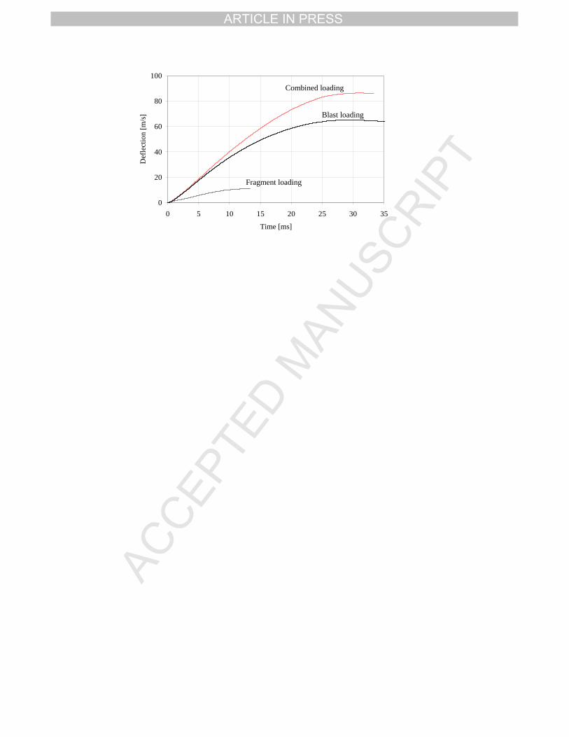
In Fig. 13 the mid-point deflections of the three wall strips subjected to blast, fragment and combined
loading, respectively, are shown. As seen, the mid-point deflection in the case of combined loading is
larger than the sum of the deflections caused by blast and fragment loading separately, which indicates a
synergy effect.
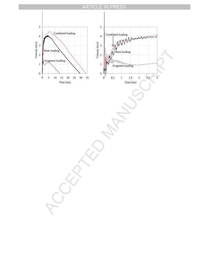
In Fig. 14 the mid-point velocities from the simulations with blast, fragment and combined loading
are shown. The velocity for combined loading is first influenced by the fragment impact, but already after
a fraction of a millisecond the velocity seems close to the velocity of the wall strip subjected to blast
loading alone. After approximately 2 ms, the velocity for combined loading increases and exceeds the
velocity for blast loading.
TPIRCSUNAM DETPECCA
ARTICLE IN PRESS
In Table 4 the mid-point deflections estimated in the numerical analyses are presented together with
results from SDOF analyses. Input parameters for the SDOF analyses are shown in Appendix A.
In the case of blast loading the estimations of the deflection made in SDOF and numerical simulations
agree well. In the case of fragment loading the difference is larger, which probably can be explained by
the limitations in the SDOF analyses to take into account e.g. the energy consumed during penetration
and subsequent crushing of the concrete, the formation of many flexural cracks, and inertia effects, which
may increase the load-bearing capacity. The results from the numerical simulation and the SDOF analysis
differ also for combined loading. The difference is even larger than in the case of fragment loading and ay
be explained by magnification of the limitations already used as explanation for the case of fragment
loading.
8 Summary and conclusions
In blast loading, the elongation of the rear face of the wall strip is localised to a few cracks where
yielding of the reinforcement takes place. In fragment loading, the flexural cracks to which the elongation
of the reinforcement is localised are numerous, the energy-absorbing capacity of the wall strip may thus
be increased.
In the simulations involving fragment loading, scabbing cracks formed due to the reflected stress
wave. The appearance of these cracks were unexpected, but was confirmed with a 2D simulation study,
indicating that the case of multi-fragment impact may lead to scabbing also when the single fragment
impact does not. It may therefore be necessary to take this effect into account in design of protective
structures. However, it is questionable whether the location and size of the scabbing cracks simulated are
realistic.
Most damage caused by the fragment impact occurs within 0.2 ms after arrival, which is short
compared to the response time of the element, indicating that in the case of combined loading the bearing
capacity and the mid-point deflection of the wall strip may be highly influenced by the fragment impact
since the structure thus loses part of its effective height.
The larger mid-point deflection of the wall strip subjected to blast loading, compared to the deflection
in the case of fragment loading, was expected since the impulse from the blast was almost 2.5 times the
impulse caused by the fragments.
TPIRCSUNAM DETPECCA
ARTICLE IN PRESS
The damage caused by combined loading is more severe than if adding the damages caused by the
blast and fragment loading treated separately. The size of the front face craters, though, is an exception
since these are larger in the case of fragment loading than in combined loading. It can be concluded that
the mid-point deflection in combined loading (85.7 mm) is larger than the sum of mid-point deflections
for blast and fragment loading treated separately (in total 76.2 mm), indicating a synergy effect in
combined loading.
Acknowledgement
The work presented in this paper is done within the research project "Concrete structures subjected
to blast and fragment impacts: dynamic behaviour of reinforced concrete", financially supported by the
Swedish Rescue Services Agency. The authors would like to thank the members of the reference group
for the project: Björn Ekengren, M.Sc., at the Swedish Rescue Services Agency, Morgan Johansson,
Ph.D., at Reinertsen AB, and Joosef Leppänen, Ph.D., at FB Engineering AB.
References
[1] Girhammar UA. Brief review of Combined Blast and Fragment Loading Effects. Report C7:90.
National Fortifications Administration, Eskilstuna, Sweden, 1990. 15 pp.
[2] ASCE. Structural Design for Physical Security – State of the Practice. Task committee: Conrath,
E.J. et al., American Society of Civil Engineers, 1999. 264 pp.
[3] Ekengren B. Skyddsrum SR 06 (Shelter regulations SR06, in Swedish). Swedish Rescue Services
Agency, Karlstad (Sweden), 2006. 113 pp.
[4] Johansson M. Structural Behaviour in Concrete Frame Corners of Civil Defence Shelters, Non-
linear Finite Element Analyses and Experiments. Doctoral Thesis, Department of Structural
Engineering, Concrete Structures, Göteborg (Sweden): Chalmers University of Technology, 2000.
220 pp.
[5] Leppänen J. Concrete Structures Subjected to Fragment Impacts, Dynamic Behaviour and Material
Modelling. Doctoral Thesis, Department of Structural Engineering and Mechanics, Concrete
Structures, Göteborg (Sweden): Chalmers University of Technology, 2004. 127 pp.
TPIRCSUNAM DETPECCA
ARTICLE IN PRESS
[6] Nyström U. Design with regard to explosions. Master’s Thesis, Department of Civil and
Environmental Engineering, Structural Engineering, Concrete Structures, Göteborg (Sweden):
Chalmers University of Technology, 2006. 205 pp.
[7] Nyström U, Leppänen J. Numerical Studies of Projectile Impacts on Reinforced Concrete. In: Fan C,
Chua HK (eds.). Proceedings of the Second International Conference on Design and Analysis of
Protective Structures, Singapore (Singapore): Nanyang Technical University, 2006. p. 310-319.
[8] ConWep. Collection of conventional weapon effects calculations based on TM 5-855-1,
Fundamentals of Protective Design for Conventional Weapons, U. S. Army Engineer Waterboys
Experiment Station, Vicksburg (VA, USA), 1992.
[9] Kingery CN, Bulmash G. Air Blast Parameters from TNT Spherical Air Burst and Hemispherical
Surface Burst. US Army Ballistic Research Laboratory Technical Report ARBRL-TR 02555,
Aberdeen Providing Ground, MD, 1984.
[10] Janzon B. Grundläggande Stridsdelsfysik (in Swedish). National Defence Research Establishment
(FOA), FOA report C 20261-D4, Stockholm (Sweden), 1978. 168 pp.
[11] Johansson M, Laine L. Bebyggelsens motståndsförmåga mot extrem dynamisk belastning,
Delrapport1: Last av luftstötvåg (The capacity of buildings to resist severe dynamic loading, Part 1:
Blast wave loading, in Swedish). Swedish Rescue Services Agency, Karlstad (Sweden) 2007.
114 pp.
[12] Baker WE. Explosions in Air. University of Texas Press, Austin (TX, US), 1973. 285 pp.
[13] U.S. Army. Fundamentals of Protective Design for Conventional Weapons. Technical Manual
TM 5-855-1. 1992. 271 pp.
[14] Forsén R, Nordström M. Damage to reinforced concrete slabs due to the combination of blast and
fragment loading. (Reprint from the Second International Conference of Structures under Shock and
Impact, Portsmouth, UK, 1992.) FOA report B 20101-2.6. National Defence Research
Establishment, Sundbyberg (Sweden), 1992. 12 pp.
[15] Curran DR. Simple fragment size and shape distribution formulae for explosively fragmenting
munitions. Int J Impact Engng 1997;20:197-208.
[16] DDESP. Methodologies for calculating primary fragment characteristics. Report No. DDESP TP 16,
Department of Defence Explosives Safety Board, Alexandra, (U.S.), 2003. 53 pp.
TPIRCSUNAM DETPECCA
ARTICLE IN PRESS
[17] Mott NF, Linfoot EH. A Theory of Fragmentation. Ministry of Supply report No A.C.3348, January
1943.
[18] Mott NF. A Theory of Fragmentation of Shells and Bombs. Ministry of Supply report No A.C.4035,
May 1943.
[19] Krauthammer T. Modern protective structures – Design, analysis and evaluation. Course notes for
course Modern Protective Structures, State College (USA), July 2006. 412 pp.
[20] Gurney RW. The Initial Velocities of Fragments from Bombs, Shells and Grenades. US Army
Ballistic Research Laboratory Report BRL 405, Aberdeen Providing Ground, MD, September 1943.
[21] Malvar LJ, Ross CA. Review of Strain Rate Effects for Concrete in Tension. ACI Mater J
1998;95(6):735-739.
[22] Bischoff PH, Perry SH. Compressive behaviour of concrete at high strain rates. Mater Struct
1991;24:425-450.
[23] Schuler H. Experimentelle und numerische Untersuchungen zur Schädigung von stoßbeanspruchtem
Beton (in German). Doctoral Thesis, Universität der Bundeswehr München, Freiburg (Germany):
Institut Kurzzeitdynamik, Ernst-Mach-Institut, 2004. 184 pp.
[24] Brara A, Klepaczko JR. Fracture energy of concrete at high loading rates in tension. Int J Impact
Engng 2007;34(3):424-435.
[25] Weerheijm J, van Doormaal JCAM. Tensile failure of concrete at high loading rates: New test data
on strength and fracture energy from instrumented spalling tests. Int J Impact Engng
2007;34(3):609-626.
[26] Nyström U. Concrete Structures Subjected to Blast and Fragment Impacts, Numerical Simulations
of Reinforced and Fibre-reinforced Concrete. Licentiate thesis. Department of Civil and
Environmental Engineering, Structural Engineering, Concrete Structures, Göteborg (Sweden):
Chalmers University of Technology, 2008. 117 pp.
[27] Boverket. Boverkets Handbok för Betongkonstruktioner BBK 04, (Boverket’s handbook for
Concrete Structures BBK 04, in Swedish). Boverket, Karlskrona (Sweden), 2004. 271 pp.
[28] ANSYS AUTODYN User Manual, Version 11.0. Concord (CA, USA): Century Dynamics Inc.,
2007. 528 pp.
TPIRCSUNAM DETPECCA
ARTICLE IN PRESS
[29] Magnusson J, Hansson H. Simuleringar av explosionsbelastade betongbalkar – en principstudie
(Numerical simulations of concrete beams – a principal study, in Swedish). National Defence
Research Establishment (FOI), FOI Report 1686--SE, Tumba (Sweden), 2005. 55 pp.
[30] Leppänen J. Splitterbelastad betong – Experiment och numeriska analyser (Fragment Impacts into
Concrete – Experiments and Numerical Analyses, in Swedish). Department of Structural
Engineering and Mechanics, Division of Concrete Structures, Chalmers University of Technology,
Report no. 03:6, Göteborg (Sweden), 80 pp.
[31] Riedel W. Beton unter dynamischen lasten, meso. und makromechanische modelle und ihre
parameter (in German). Doctoral Thesis, Universität der Bundeswehr München, Freiburg
(Germany): Institut Kurzzeitdynamik, Ernst-Mach-Institut, 2000. 210 pp.
[32] AUTODYN Theory Manual, Revision 4.3. Concord (CA, USA), Century Dynamics Inc., 2005.
227 pp.
[33] Magnusson J, Hallgren M. High Performance Concrete Beams Subjected to shock Waves from Air
Blast. National Defence Research Establishment (FOA), FOA report 00-01586-311--SE, Tumba
(Sweden), 2000. 86 pp.
[34] Johansson M. Stötvågsutbreding i luft (Blast wave in air, in Swedish). Swedish Rescue Services
Agency, Karlstad (Sweden), 2002. 60 pp.
Appendix A
Since an ideal-plastic material behaviour was assumed for the internal resistance of the SDOF system
the equation of motion used to describe the movement of the mid-point in a simply supported beam, with
mass, M, and length, L, subjected to a uniformly distributed load, q(t), can be simplified to:
LtqRuM ⋅=+ )(32
&& (1)
where u&& is the mid-point acceleration of the beam [6].
When assuming an ideal-plastic material behaviour, the internal resistance, R, in Eq. 1 equals the
maximum value of the load that the beam (or wall strip) can bear, i.e. R=Rm given that the displacement
u≠0. Before any displacement occurs (u=0), if the external load is smaller than the maximum load-
TPIRCSUNAM DETPECCA
ARTICLE IN PRESS
bearing capacity (P(t)<Rm), the internal resistance equals the external load (R=P(t)). According to [13] the
dynamic internal resistance can be estimated as 1.3 times the static internal resistance, possible
explanation to this is given in [26]. The increase in load-bearing capacity in the case of dynamic loading,
compared to static loading, is reported in [33] where blast-loaded concrete beams are studied, and
supports the value used in [13] for increased internal resistance to dynamic loads. In numerical
simulations of blast-loaded walls conducted and reported by Johansson [34] an increased load-bearing
capacity was observed. [34] explained this by the appearance of large normal forces, which probably can
be explained by inertia effects.
The dynamic internal resistance, Rm, is for a simply supported beam with uniformly distributed load
thus calculated as:
LM
R Rdm
83.1= (2)
where MRd is the static moment capacity of the beam.
TPIRCSUNAM DETPECCA
ARTICLE IN PRESS
Fig. 1. Time of arrival for blast wave and fragments as functions of the stand-off for a 250 kg GP-bomb with 50
weight per cent TNT, from [5].
Fig. 2. Incident blast wave idealisation for 125 kg TNT at 5 meters stand-off, based on [4].
Fig. 3. Positive phase of reflected and incident blast wave for 125 kg TNT at 5 metres stand-off, calculated
according to [13].
Fig. 4. Civil defence shelter and simplified model of one of its walls.
Fig. 5. The reflected pressure load as function of time for 125 kg TNT at a distance of 5.0 metres, according to
ConWep [8], and the simplified relationship for this which is used in this study, based on [4].
Fig. 6. Mid-point deflection of wall strip subjected to blast load and fragment impulse load, calculated with SDOF
method. Since the response of simultaneous loading and loading where fragments arrive first and blast at time of
maximum velocity are almost identical these lines are seen as one in the figure.
Fig. 7. Numerical mesh of wall strip used in simulations, also showing reinforcement in the modelled wall strip.
Fig. 8. Response of wall strip subjected to blast load at time of maximum mid-point deflection.
Fig. 9. Response of wall strip subjected to fragment impacts at time of maximum mid-point deflection.
Fig. 10. Response of wall strip subjected to fragment impacts at time (a) 0.25 ms, (b) 0.6 ms and (c) 9 ms after time
of fragment arrival, seen at section of reinforcement.

TPIRCSUNAM DETPECCA
ARTICLE IN PRESS
Fig. 11. Response of wall strip subjected to combined blast and fragment loading at time of maximum mid-point
deflection.
Fig. 12. Schematically shown confinement effects from blast loading, σblast, on concrete element compressed by
σfragment due to fragment penetration.
Fig. 13. Mid-point deflection of wall strip subjected to combined, blast and fragment loading from numerical
simulations.
Fig. 14. Mid-point velocity of wall strip subjected to blast and fragment loading from numerical simulations.
Table 1.
Employed material data for concrete, input to the RHT model.
Table 2.
Employed material data for reinforcing steel.
Table 3.
Employed material data for supports and fragments.
Table 4.
Mid-point deflections.

TPIRCSUNAM DETPECCA
ARTICLE IN PRESS
Equation of state P alpha Brittle to ductile transition 1.05000E-02 (-) Reference density 2.75000E+00 (g/cm3) G (elastic)/(elastic-plastic) 2.00000E+00 (-) Porous density 2.31400E+00 (g/cm3) Elastic strength/ft 7.00000E-01 (-) Porous soundspeed 2.92000E+03 (m/s) Elastic strength/fc 5.30000E-01 (-) Initial compaction pressure 2.33000E+04 (kPa) Fractured strength constant B 1.60000E+00 (-) Solid compaction pressure 6.00000E+06 (kPa) Fractured strength exponent M 6.10000E-01 (-) Compaction exponent 3.00000E+00 (-) Compressive strain rate exponent α 3.20000E-02 (-) Solid EOS Polynomial Tensile strain rate exponent δ 3.60000E-02 (-) Bulk modulus A1 3.52700E+07 (kPa) Max. fracture strength ratio 1.00000E+20 (-) Parameter A2 3.95800E+07 (kPa) Use CAP on elastic surface? Yes Parameter A3 9.04000E+06 (kPa) Failure RHT concrete Parameter B0 1.22000E+00 (-) Damage constant D1 4.00000E-02 (-) Parameter B1 1.22000E+00 (-) Damage constant D2 1.00000E+00 (-) Parameter T1 3.52700E+07 (kPa) Minimum strain to failure 1.00000E-02 (-) Parameter T2 0.00000E+00 (kPa) Residual shear modulus fraction 1.30000E-01 (-) Reference temperature 3.00000E+02 (K) Tensile failure Principal stress Specific heat 6.54000E+02 (J/kgK) Principal tensile failure stress 3.50000E+03 (kPa) Compaction curve Standard Max. principal stress difference/2 1.01000E+20 (kPa) Strength RHT concrete Crack softening Yes Shear modulus 1.67000E+07 (kPa) Fracture energy, GF 1.20000E+02 (J/m2) Compressive strength (fc) 3.50000E+04 (kPa) Flow rule Bulking (Associative) Tensile strength (ft/fc) 1.00000E-01 (-) Stochastic failure No Shear strength (fs/fc) 1.80000E-01 (-) Erosion Geometric strain Intact failure surface constant A 1.60000E+00 (-) Erosion strain 2.00000E+00 (-) Intact failure surface exponent N 6.10000E-01 (-) Type of geometric strain Instantanous Tens./Comp. meridian ratio (Q) 6.80500E-01 (-)

TPIRCSUNAM DETPECCA
ARTICLE IN PRESS
Equation of state Linear Eff. Plastic strain #10 1.00000E+01 (-) Reference density 7.83000E+00 (g/cm3) Yield stress #1 5.62000E+05 (kPa) Bulk modulus 1.59000E+08 (kPa) Yield stress #2 5.68000E+05 (kPa) Reference temperature 3.00000E+02 (K) Yield stress #3 6.27000E+05 (kPa) Specific heat 4.77000E+00 (J/kgK) Yield stress #4 6.78000E+05 (kPa) Thermal conductivity 0.00000E+00 (J/mKs) Yield stress #5 7.15000E+05 (kPa) Strength Piecewise JC Yield stress #6 7.46000E+05 (kPa) Shear modulus 8.18000E+07 (kPa) Yield stress #7 7.76000E+05 (kPa) Yield stress (zero plastic strain) 5.49330E+05 (kPa) Yield stress #8 7.95000E+05 (kPa) Eff. Plastic strain #1 6.70000E-03 (-) Yield stress #9 7.95000E+05 (kPa) Eff. Plastic strain #2 1.62000E-02 (-) Yield stress #10 7.95000E+05 (kPa) Eff. Plastic strain #3 2.86000E-02 (-) Strain rate constant C 0.00000E+00 (-) Eff. Plastic strain #4 4.57000E-02 (-) Thermal softening exponent m 0.00000E+00 (-) Eff. Plastic strain #5 6.45000E-02 (-) Melting temperature 0.00000E+00 (K) Eff. Plastic strain #6 9.21000E-02 (-) Ref. strain rate (1/s) 1.00000E+00 (-) Eff. Plastic strain #7 1.27800E-01 (-) Failure None Eff. Plastic strain #8 1.79200E-01 (-) Erosion None Eff. Plastic strain #9 1.79201E-01 (-)

TPIRCSUNAM DETPECCA
ARTICLE IN PRESS
Equation of state Linear Equation of state Linear Reference density 7.83000E+00 (g/cm3) Reference density 7.83000E+00 (g/cm3) Bulk modulus 1.59000E+08 (kPa) Bulk modulus 1.59000E+08 (kPa) Reference temperature 3.00000E+02 (K) Reference temperature 3.00000E+02 (K) Specific heat 4.77000E+00 (J/kgK) Specific heat 4.77000E+00 (J/kgK) Thermal conductivity 0.00000E+00 (J/mKs) Thermal conductivity 0.00000E+00 (J/mKs) Strength Elastic Strength von Mises Shear modulus 8.18000E+07 (kPa) Shear modulus 8.18000E+07 (kPa) Failure None Yield stress 8.00000E+05 (kPa) Erosion None Failure None Erosion None

TPIRCSUNAM DETPECCA
ARTICLE IN PRESS
Load uAUTODYN [mm] uSDOF [mm]
Blast 65.2 64.0 Fragment 11.0 13.9 Combined 85.7 139
TPIRCSUNAM DETPECCA
ARTICLE IN PRESS
0
2
4
6
8
10
0 2 4 6 8 10Distance [m]
FragmentsBlast wave
Arrival time [ms]
TPIRCSUNAM DETPECCA
ARTICLE IN PRESS
P
T+ T - t
P0+Ps+
P0 P0-Ps
-
ta
TPIRCSUNAM DETPECCA
ARTICLE IN PRESS
0
1000
2000
3000
4000
5000
0 1 2 3 4 5
Time [ms]
Pres
sure
, P [k
Pa]
Incident pressureReflected pressure
TPIRCSUNAM DETPECCA
ARTICLE IN PRESS
5.0 m
3.0
m
0.2
m0.
35 m
0.35 m
2.7
m
TPIRCSUNAM DETPECCA
ARTICLE IN PRESS
0
1000
2000
3000
4000
5000
0 1 2 3 4 5
Time [ms]
Pres
sure
, P [k
Pa]
Simplified relationConWep
Time [ms]
Pressure [kPa]
0.0 5 006 0.3 2 930 0.6 1 713 1.0 836 1.5 340 2.0 137 3.0 22
8.974 0
TPIRCSUNAM DETPECCA
ARTICLE IN PRESS
020406080
100120140160
0 10 20 30 40 50
Time [ms]
Def
lect
ion
[mm
] Fragments arrive at maximum velocity
Fragments arrive at maximum deflection
Blast arrvives at maximum velocity
Blast arrives at maximum deflection
Simultaneous loading
TPIRCSUNAM DETPECCA
ARTICLE IN PRESS
168
1344
84 102 8+240 [mm]
Transverse reinforcement
Border between fine and coarse mesh
x y
204
204
192
204
204
192
204
Fragment Longitudinal reinforcement
TPIRCSUNAM DETPECCA
ARTICLE IN PRESS
Top view
Reinforcement side
Middle of wall strip
TPIRCSUNAM DETPECCA
ARTICLE IN PRESS
Top view
Reinforcement side
Middle of wall strip
TPIRCSUNAM DETPECCA
ARTICLE IN PRESS
a)
b)
c)

TPIRCSUNAM DETPECCA
ARTICLE IN PRESS
Top view
Reinforcement side
Middle of wall strip

TPIRCSUNAM DETPECCA
ARTICLE IN PRESS
σblast
σblast
σfragment σfragment Concrete surface
Penetrating fragment
TPIRCSUNAM DETPECCA
ARTICLE IN PRESS
0
20
40
60
80
100
0 5 10 15 20 25 30 35
Time [ms]
Def
lect
ion
[m/s
]
Combined loading
Fragment loading
Blast loading
TPIRCSUNAM DETPECCA
ARTICLE IN PRESS
0
1
2
3
4
5
0 0,5 1 1,5 2 2,5 3
Time [ms]
Vel
ocity
[m/s]
0
1
2
3
4
5
0 5 10 15 20 25 30 35
Time [ms]
Vel
ocity
[m/s]
Combined loading
Fragment loading
Blast loading
Combined loading
Fragment loading
Blast loading