Embed Size (px)
Citation preview

Proceedings of the
International Conference on Mechanical Engineering 2011 (ICME2011) 18-20 December 2011, Dhaka, Bangladesh
ICME11-FL-049
©ICME2011 1 FL-049
1. INTRODUCTION The turbulent forced heat transfer in ducts is
encountered in different Industrial applications. Laminar
fluid flow with convective heat transfer through
rectangular duct is usually encountered in a good number
of engineering applications such as solar collectors,
concentrators, heat exchangers and cooling of modern
electronic equipments etc. The analysis becomes
complicated when the flow become turbulent. The
analysis of such a flow in a rectangular elbow is important
in connection with several Engineering applications like
heat exchanger, fluid transport ducting system, air
conditioning devices etc. The analysis of such flow is
complicated owing to the complicacy of the geometry.
Apart from this, the presence of non-uniformity of the
flow enhances the severity of the problem concerned to be
analyzed.
Review of literatures reveals that many attempts have
been made to numerically simulate forced convective
turbulent flow in the horizontal and vertical straight ducts
of constant cross section. Cheng et al. [1] studied
numerically combined free and forced convection heat
transfer through horizontal rectangular
channel under buoyancy conditions of axially uniform
heat flux (UHF) and peripherally uniform wall
temperature (UWT) for steady fully developed flow by
using the methods of Patankar and Spalding [2]. Cheng
and Weng [3] carried out numerical study on vertical
rectangular duct with one wall uniform high temperature
for developing flow of mixed convection. Payvar [4]
demonstrated his numerical results for heat transfer
enhancement in laminar flow of viscoelastic fluids
through rectangular ducts. Yang and Kuan [5] obtained
the mean and turbulent flow velocities of gas and
particulate phases inside a curved 900 bend. Gas-liquid
two phase turbulent flow simulation for a 900 bend elbow
was reported by Spedding and Benard [6]. An
experimental investigation of turbulent fluid flow through
a rectangular elbow with estimation of coefficient of
friction was made by Mandal et al [7]. A comparative
numerical study between three types of turbulent models
e.g. standard k-ε, k-ω and Reynolds Stress models with
flow visualization for only the turbulent air flow in a two-
dimensional rectangular elbow has been subsequently
made by the same authors [8]. Özisik [9] derived some
expressions for friction factor, pressure drop and heat
NUMERICAL STUDY FOR FORCED CONVECTIVE TURBULENT
FLOW IN A RECTANGULAR ELBOW
Snehamoy Majumder , Debasish Roy
, Rabin Debnath, Arindam Mandal and Somnath Bhattacharjee
Department of Mechanical Engineering, Jadavpur University, INDIA,
ABSTRACT In this paper, the forced convective heat transfer of turbulent fluid flow is studied numerically in a
rectangular elbow at a prescribed uniform wall temperature and specified inlet conditions. The analysis of
the turbulent flow has been carried out in two dimensional Cartesian co-ordinates considering steady,
incompressible and non-reacting fluid flow through the elbow for the sake of simplicity. The working
fluid is air and it is admitted through the inlet of the duct at a temperature less than the wall temperature.
The velocity, temperature and local average Nusselt number distributions in the whole flow field are
estimated numerically by solving the Navier–Stokes and the Energy equations along-with standard
turbulent model using FLUENT 6.3.26.
Keywords: Rectangular Elbow, Turbulent Flow, Equation
©ICME2011 2 FL-049
transfer coefficient for the turbulent forced convection
flow in circular ducts only. The turbulent flow and forced
convective heat transfer in both straight and wavy ducts,
with rectangular, trapezoidal and triangular cross-sections,
under fully developed conditions, were numerically
predicted by Rokni and Gatski [10]. Majumder and Sanyal
[11] studied the relaminarization of Turbulent fluid flow
numerically. The developing mixed convection heat
transfer in inclined rectangular ducts with wall
transpiration effects had been numerically investigated by
Jang et al. [12].
In the present paper, the turbulent fluid flow with
forced convective heat transfer is studied numerically in a
two-dimensional rectangular elbow having a prescribed
uniform wall temperature (UWT) and different inlet
conditions.
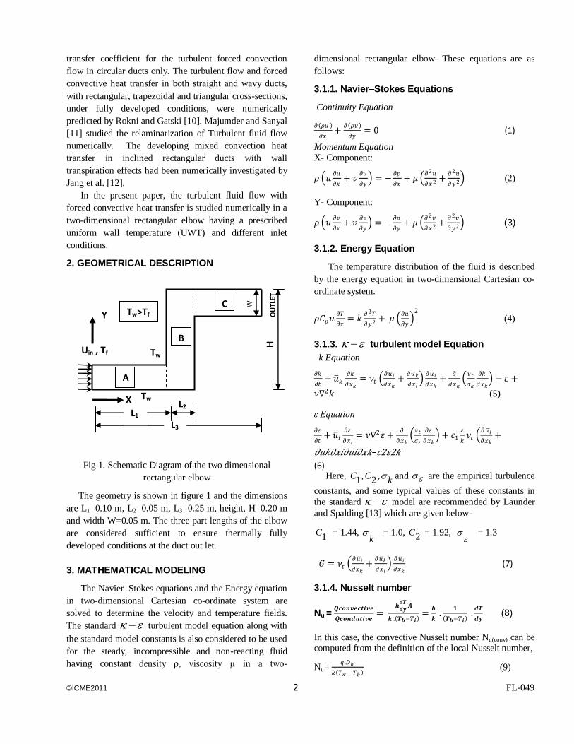
2. GEOMETRICAL DESCRIPTION
Fig 1. Schematic Diagram of the two dimensional
rectangular elbow
The geometry is shown in figure 1 and the dimensions
are L1=0.10 m, L2=0.05 m, L3=0.25 m, height, H=0.20 m
and width W=0.05 m. The three part lengths of the elbow
are considered sufficient to ensure thermally fully
developed conditions at the duct out let.
3. MATHEMATICAL MODELING
The Navier–Stokes equations and the Energy equation
in two-dimensional Cartesian co-ordinate system are
solved to determine the velocity and temperature fields.
The standard turbulent model equation along with
the standard model constants is also considered to be used
for the steady, incompressible and non-reacting fluid
having constant density ρ, viscosity µ in a two-
dimensional rectangular elbow. These equations are as
follows:
3.1.1. Navier–Stokes Equations
Continuity Equation
𝜕 𝜌𝑢
𝜕𝑥+
𝜕 𝜌𝑣
𝜕𝑦= 0 (1)
Momentum Equation
X- Component:
𝜌 𝑢𝜕𝑢
𝜕𝑥+ 𝑣
𝜕𝑢
𝜕𝑦 = −
𝜕𝑝
𝜕𝑥+ 𝜇
𝜕2𝑢
𝜕𝑥2 +𝜕2𝑢
𝜕𝑦2 (2)
Y- Component:
𝜌 𝑢𝜕𝑣
𝜕𝑥+ 𝑣
𝜕𝑣
𝜕𝑦 = −
𝜕𝑝
𝜕𝑦+ 𝜇
𝜕2𝑣
𝜕𝑥2 +𝜕2𝑣
𝜕𝑦2 (3)
3.1.2. Energy Equation
The temperature distribution of the fluid is described
by the energy equation in two-dimensional Cartesian co-
ordinate system.
𝜌𝐶𝑝𝑢𝜕𝑇
𝜕𝑥= 𝑘
𝜕2𝑇
𝜕𝑦2 + 𝜇 𝜕𝑢
𝜕𝑦
2
(4)
3.1.3. turbulent model Equation
k Equation
𝜕𝑘
𝜕𝑡+ 𝑢 𝑘
𝜕𝑘
𝜕𝑥𝑘= 𝜈𝑡
𝜕𝑢 𝑖
𝜕𝑥𝑘+
𝜕𝑢 𝑘
𝜕𝑥𝑖
𝜕𝑢 𝑖
𝜕𝑥𝑘+
𝜕
𝜕𝑥𝑘 𝜈𝑡
𝜎𝑘
𝜕𝑘
𝜕𝑥𝑘 − 𝜀 +
𝜈∇2𝑘 (5)
ε Equation
𝜕𝜀
𝜕𝑡+ 𝑢 𝑖
𝜕𝜀
𝜕𝑥𝑖= 𝜈∇2𝜀 +
𝜕
𝜕𝑥𝑘 𝜈𝑡
𝜎𝜀
𝜕𝜀
𝜕𝑥𝑘 + 𝑐1
𝜀
𝑘𝜈𝑡
𝜕𝑢 𝑖
𝜕𝑥𝑘+
𝜕𝑢𝑘𝜕𝑥𝑖𝜕𝑢𝑖𝜕𝑥𝑘−𝑐2𝜀2𝑘
(6) Here,
kCC ,2,1 and are the empirical turbulence
constants, and some typical values of these constants in
the standard model are recommended by Launder
and Spalding [13] which are given below-
1C = 1.44,
k = 1.0, 2C = 1.92,
= 1.3
𝐺 = 𝜈𝑡 𝜕𝑢 𝑖
𝜕𝑥𝑘+
𝜕𝑢 𝑘
𝜕𝑥𝑖
𝜕𝑢 𝑖
𝜕𝑥𝑘 (7)
3.1.4. Nusselt number
Nu = 𝑸𝒄𝒐𝒏𝒗𝒆𝒄𝒕𝒊𝒗𝒆
𝑸𝒄𝒐𝒏𝒅𝒖𝒕𝒊𝒗𝒆=
𝒉𝒅𝑻
𝒅𝒚.𝑨
𝒌 . 𝑻𝒃−𝑻𝒊 =
𝒉
𝒌 .
𝟏
𝑻𝒃−𝑻𝒊 .𝒅𝑻
𝒅𝒚 (8)
In this case, the convective Nusselt number Nu(conv) can be
computed from the definition of the local Nusselt number,
Nu= 𝑞 .𝐷ℎ
𝑘 𝑇𝑤 −𝑇𝑏 (9)
W
X Tw
Tw Uin , Tf
OU
TLE
T
Tw>Tf Y
L3
=
L2 L1
=
H
A
B
C
©ICME2011 3 FL-049
Where q is the convective heat flux [W/m2] depending on
the quantity to be evaluated. The bulk mean temperature
Tb at the duct cross-section is given by,
Tb (X) =1
𝑢 𝑋 𝐴 𝑢 𝑥,𝑦, 𝑧 𝑇 𝑥, 𝑦, 𝑧 𝑑𝐴 (10)
Where u(X) is the average fluid velocity at any cross-
section of the duct.
The average Nusselt number for each cross-section along
the heated wall is then evaluated from
Nu(avg) = 𝑁𝑢𝑌=1𝑌=0
𝑁 (11)
Where N is the number of Nu nodal values on the heated
wall.
3.2. Boundary Conditions
All the equations given in articles 3.1.1 to 3.1.3 are
solved for the following cases of the different boundary
conditions:
(i) A steady fully developed turbulent of a viscous
incompressible Newtonian air flow is admitted in an
elbow duct of rectangular cross-section.
(ii) u (0,y) = u(y,0)= 0; uinlet = 5 m/s
(iii) Tinlet = Tf =300K; TWall > Tf ; Twall = 330K
(iv) Outflow is fully developed; No-slip at walls
3.3. Fluid Properties
The fluid is supplied through the duct at a prescribed
uniform speed 5m/s and at a temperature 300K. The fluid
used is air of density ρ = 1.225kg/m3 and viscosity μ =
1.7894X10⁻⁵ kg/(m.s). The duct material is considered
Aluminium metal of thickness 0.02 m, density ρ =
2719kg/m3 and thermal conductivity k = 202.4W/m-K.
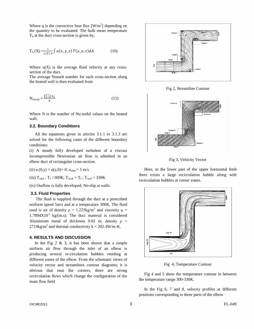
4. RESULTS AND DISCUSSION
In the Fig 2 & 3, it has been shown that a simple
uniform air flow through the inlet of an elbow is
producing several re-circulation bubbles residing at
different zones of the elbow. From the schematic views of
velocity vector and streamlines contour diagrams; it is
obvious that near the corners, there are strong
recirculation flows which change the configuration of the
main flow field
Fig 2, Streamline Contour
Fig 3, Velocity Vector
Here, in the lower part of the upper horizontal limb
there exists a large recirculation bubble along with
recirculation bubbles at corner zones.
Fig 4, Temperature Contour
Fig 4 and 5 show the temperature contour in between
the temperature range 300-330K.
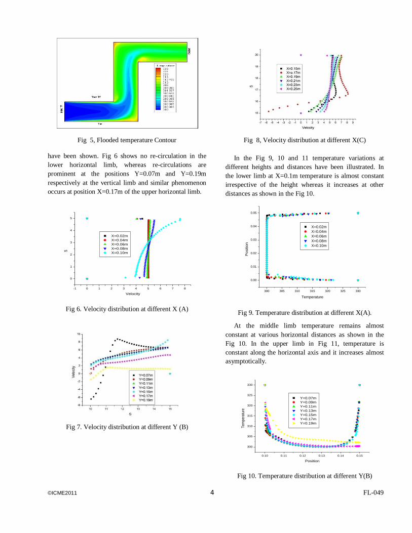
In the Fig 6, 7 and 8, velocity profiles at different
positions corresponding to three parts of the elbow
©ICME2011 4 FL-049
Fig 5, Flooded temperature Contour
have been shown. Fig 6 shows no re-circulation in the
lower horizontal limb, whereas re-circulations are
prominent at the positions Y=0.07m and Y=0.19m
respectively at the vertical limb and similar phenomenon
occurs at position X=0.17m of the upper horizontal limb.
Fig 6. Velocity distribution at different X (A)
Fig 7. Velocity distribution at different Y (B)
Fig 8, Velocity distribution at different X(C)
In the Fig 9, 10 and 11 temperature variations at
different heights and distances have been illustrated. In
the lower limb at X=0.1m temperature is almost constant
irrespective of the height whereas it increases at other
distances as shown in the Fig 10.
Fig 9. Temperature distribution at different X(A).
At the middle limb temperature remains almost
constant at various horizontal distances as shown in the
Fig 10. In the upper limb in Fig 11, temperature is
constant along the horizontal axis and it increases almost
asymptotically.
Fig 10. Temperature distribution at different Y(B)
-1 0 1 2 3 4 5 6 7 8
0
1
2
3
4
5
S
Velocity
X=0.02m
X=0.04m
X=0.06m
X=0.08m
X=0.10m
300 305 310 315 320 325 330
0.00
0.01
0.02
0.03
0.04
0.05
Po
sitio
n
Temperature
X=0.02m
X=0.04m
X=0.06m
X=0.08m
X=0.10m
0.10 0.11 0.12 0.13 0.14 0.15
300
305
310
315
320
325
330
Te
mp
era
ture
Position
Y=0.07m
Y=0.09m
Y=0.11m
Y=0.13m
Y=0.15m
Y=0.17m
Y=0.19m
©ICME2011 5 FL-049
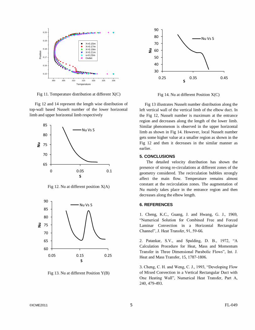
Fig 11. Temperature distribution at different X(C)
Fig 12 and 14 represent the length wise distribution of
top-wall based Nusselt number of the lower horizontal
limb and upper horizontal limb respectively
Fig 12. Nu at different position X(A)
Fig 13. Nu at different Position Y(B)
Fig 14. Nu at different Position X(C)
Fig 13 illustrates Nusselt number distribution along the
left vertical wall of the vertical limb of the elbow duct. In
the Fig 12, Nusselt number is maximum at the entrance
region and decreases along the length of the lower limb.
Similar phenomenon is observed in the upper horizontal
limb as shown in Fig 14. However, local Nusselt number
gets some higher value at a smaller region as shown in the
Fig 12 and then it decreases in the similar manner as
earlier.
5. CONCLUSIONS
The detailed velocity distribution has shown the
presence of strong re-circulations at different zones of the
geometry considered. The recirculation bubbles strongly
affect the main flow. Temperature remains almost
constant at the recirculation zones. The augmentation of
Nu mainly takes place in the entrance region and then
decreases along the elbow length.
6. REFERENCES
1. Cheng, K.C., Guang, J. and Hwang, G. J., 1969,
“Numerical Solution for Combined Free and Forced
Laminar Convection in a Horizontal Rectangular
Channel”, J. Heat Transfer, 91, 59-66.
2. Patankar, S.V., and Spalding, D. B., 1972, “A
Calculation Procedure for Heat, Mass and Momentum
Transfer in Three Dimensional Parabolic Flows”, Int. J.
Heat and Mass Transfer, 15, 1787-1806.
3. Cheng, C. H. and Weng, C. J., 1993, “Developing Flow
of Mixed Convection in a Vertical Rectangular Duct with
One Heating Wall”, Numerical Heat Transfer, Part A,
240, 479-493.
300 305 310 315 320 325 330
0.15
0.16
0.17
0.18
0.19
0.20
Positio
n
Temperature
X=0.15m
X=0.17m
X=0.19m
X=0.21m
x=0.23m
Outlet
65
70
75
80
85
0 0.05 0.1
Nu
S
Nu Vs S
60
65
70
75
80
85
90
0.05 0.15 0.25
Nu
S
Nu Vs S
30
40
50
60
70
80
90
0.25 0.35 0.45
Nu
S
Nu Vs S
©ICME2011 6 FL-049
4. Payvar, P., 1997, “Heat Transfer Enhancement in
Laminar Flow of Viscoelastic Fluids through Rectangular
Ducts”, Int. J. Heat Mass Transfer, 40(3), 745-756.
5. Yang, W. and Kuan, B., 2006, “Experimental
Investigation of Dilute Turbulent Particulate Flow inside a
curved 90-degree bend”, Chemical Engineering Science,
61, 3593-3601.
6. Spedding, P.L. and Benard, E., 2007,”Gas-liquid two
phase flow through a vertical 90-degree elbow bend”,
Experimental Thermal Fluid Science, 31, 761-769.
7. Mandal, A., Bhattacharjee, S., Debnath, R., Roy, D. and
Majumder, S., 2010, “Experimental Investigation of
Turbulent Fluid Flow through a Rectangular Elbow”, Int.
J. Engg. Science and Technology, 2(6), 1500-1506.
8. Debnath, R., Bhattacharjee, S., Mandal, A., Roy, D. and
Majumder, S., 2010, “A Comparative Study with flow
Visualization of Turbulent fluid flow in an Elbow”, Int. J.
Engg. Science and Technology, 2(9), 4108-4121
9. Özisik, M. N., 1985, “Heat Transfe: A Basic
Approach”, McGraw-Hill Book Company, Singapore, Int.
Edition, 310-317.
10. Rokni, M. and Gatski, T.B., 2001, “Predicting
Turbulent Convective Heat transfer in fully developed
duct flows”, Int. J. Heat and Fluid Flow, 22, 381-392.
11. Majumder, S. and Sanyal, D., 2010, “Relaminarization
of Axisymmetric Turbulent Flow with Combined Axial
Jet and Side Injection in a Pipe” ASME Journal of Fluids
Engineering, 132:101101-1-101101-6.
12. Jang, J., Chiu, H. and Yan, W., 2010, “Wall
Transpiration Effects on Developing Mixed Convection
heat transfer in Inclined Rectangular Ducts’, J. Marine
Science and Technology, 18(2), 249-258.
13. Launder, B. E. and Spalding, D.B., 1974, “The
Numerical Computation of Turbulent Flows”, Computer
Methods in Applied Mechanics, 3, 269-289.
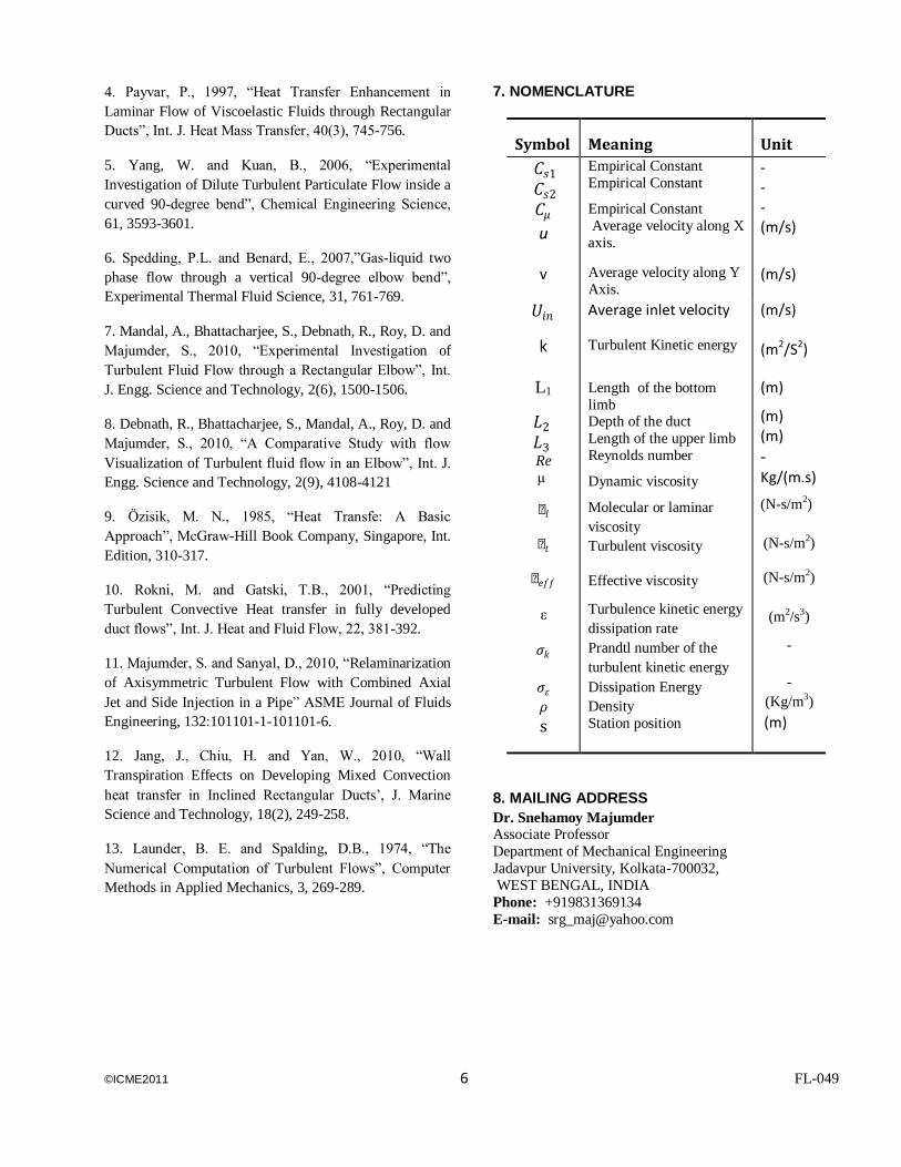
7. NOMENCLATURE
Symbol Meaning Unit
𝐶𝑠1 𝐶𝑠2 𝐶𝜇
u
Empirical Constant
Empirical Constant
Empirical Constant
Average velocity along X
axis.
- - - (m/s)
v Average velocity along Y
Axis. (m/s)
𝑈𝑖𝑛
k
L1
𝐿2 𝐿3 Re
μ
µ𝑙
µ𝑡
µ𝑒𝑓𝑓
ε
𝜎𝑘
𝜎𝜀
𝜌 s
Average inlet velocity
Turbulent Kinetic energy
Length of the bottom
limb Depth of the duct
Length of the upper limb
Reynolds number
Dynamic viscosity
Molecular or laminar
viscosity
Turbulent viscosity
Effective viscosity
Turbulence kinetic energy
dissipation rate
Prandtl number of the
turbulent kinetic energy
Dissipation Energy
Density
Station position
(m/s) (m2/S2)
(m)
(m) (m)
- Kg/(m.s)
(N-s/m2)
(N-s/m2)
(N-s/m2)
(m2/s3)
-
-
(Kg/m3)
(m)
8. MAILING ADDRESS
Dr. Snehamoy Majumder
Associate Professor
Department of Mechanical Engineering
Jadavpur University, Kolkata-700032,
WEST BENGAL, INDIA
Phone: +919831369134
E-mail: [email protected]


![Catalog Icme Ecab[1]](https://img.pdfslide.net/doc/110x75/544c3a1caf7959a4438b59fd/catalog-icme-ecab1.jpg)