Embed Size (px)
Citation preview
117
International Journal of Thermal Technologies, Vol.1, No.1 (Dec. 2011) ISSN 2277 - 4114
Research Article
Numerical Study of Pressure and Velocity Distribution Analysis of Centrifugal
Pump
Munish Guptaa, Satish Kumar
b, Ayush Kumar
c
aDepartment of Mechanical Engineering, Kurushetra University, Kurushetra
bDepartment of Mechanical Engineering, Thapar University, Patiala-147004
Accepted 20 Nov. 2011, Available online 1 Dec. 2011
Abstract
Centrifugal pumps are used for transportation of solids and liquid over short to medium distance through the
pipelines. A centrifugal pump designed to handle the liquids is normally single stage, end suction type having radial
or mixed flow configuration of blades. Present work is aimed to analyze the pressure and velocity distribution inside
the pump passage using the ANSYS-CFX computational fluid dynamics simulation tool.
Keywords: Centrifugal pump, pressure distribution, velocity distribution, computational fluid dynamics.
1. Introduction
1Centrifugal pumps are used in a variety of applications,
such as, water supply and irrigation, power –generating
utilities, flood control, sewage handling and treatment,
process industries, transporting liquid-solid mixtures.
Conventional design method of centrifugal pump are
largely based on the application of empirical and semi-
empirical rules along with the use of available
information in the form of different types of charts and
graphs as proposed by successful designers [5,6]. As the
design of centrifugal pump involve a large number of
interdependent variables, several other alternative design
are possible for same duty. Computational fluid dynamics
(CFD) is being increasingly applied in the design of the
centrifugal pumps. 3-D numerical computational fluid
dynamics tool can be used for simulation of the flow field
characteristics inside the turbo machinery. Numerical
simulation makes it possible to visualize the flow
condition inside a centrifugal pump, and provides the
valuable hydraulic design information of the centrifugal
pumps. Zhou et.al 2003 proposed a numerical method for
calculating the distribution of solid particles
concentration in centrifugal pump impeller. They used
finite element technique to solve the convection-diffusion
differential equation between blades. By using this
method they predicted best optimum impeller design.
Nursen.et.al 2003 have developed a computer program
for selection of centrifugal pumps by assuming that the
head developed, the input power and NPSH of the pump
could be represented in the form of polynomial of the
* Corresponding author’s email: [email protected]
flow rate. They have also suggested separate procedure
for correcting the pump performance for settling and non-
settling slurries. Anagnostopoulos, J. S 2006 developed a
2-dimensional computer program based on Galerkin finite
element method to solve two dimensional turbulent flow
in a centrifugal pump. A mixing length model was used
for turbulent stresses. Through this program they found
2.5% difference in inflow and outflow and predicted the
recirculation in casing when flow rate exceeds the design
flow. They have studied pump off-design performance
using the commercial software Fluent. They also
predicted reverse flow in the impeller shroud region at
small flow rates. They validated the predicted results of
the head-flow curves, diffuser inlet pressure distribution
and impeller radial forces by comparing with the
experimental data over the entire flow range. They
observed back flow at small flow rates, however no back
flow was observed at higher flow rate. Present work is
aimed to analyze the pressure and velocity distribution
inside the pump passage using the ANSYS-CFX
computational fluid.
2. Design of centrifugal pump
Present work is carried out under the following
assumptions, the flow comes in through the inlet without
any pre-swirl, the flow in the van less space is of a free-
vortex type, and the volute casing is constructed of
gradually increasing circular cross-sections with a
constant average velocity. For design of the centrifugal
pump input data are design specifications, geometrical
and hydraulic variables, given below. Geometrical and
M. Gupta et al International Journal of Thermal Technologies, Vol.1, No.1 (Dec.2011)
118
hydraulic parameters are calculated with the help of
conventional design methods .
Design Specification
Design of the pump input data: volume flow rate, total
pressure head, specific speed, density of liquid, operating
fluid viscosity.
Geometric parameter
Vane angle, number of vanes, impeller discharge width,
hub/tip ratio, inclination of the mean stream line to axial
direction.
Hydraulic parameter
Flow coefficient, head coefficient, blade velocity, relative
velocity and other hydraulic parameter needed to describe
the flow direction and magnitudes become direct function
of geometry.
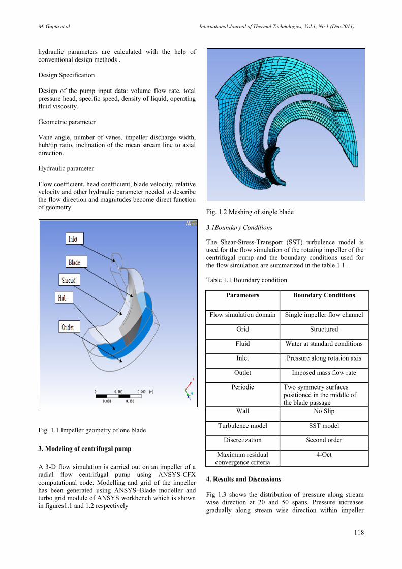
Fig. 1.1 Impeller geometry of one blade
3. Modeling of centrifugal pump
A 3-D flow simulation is carried out on an impeller of a
radial flow centrifugal pump using ANSYS-CFX
computational code. Modelling and grid of the impeller
has been generated using ANSYS–Blade modeller and
turbo grid module of ANSYS workbench which is shown
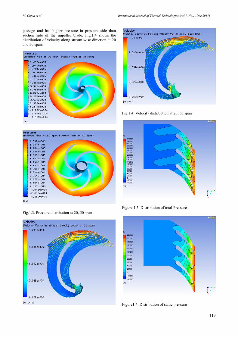
in figures1.1 and 1.2 respectively
Fig. 1.2 Meshing of single blade
3.1Boundary Conditions
The Shear-Stress-Transport (SST) turbulence model is
used for the flow simulation of the rotating impeller of the
centrifugal pump and the boundary conditions used for
the flow simulation are summarized in the table 1.1.
Table 1.1 Boundary condition
Parameters Boundary Conditions
Flow simulation domain Single impeller flow channel
Grid Structured
Fluid Water at standard conditions
Inlet Pressure along rotation axis
Outlet Imposed mass flow rate
Periodic Two symmetry surfaces
positioned in the middle of
the blade passage
Wall No Slip
Turbulence model SST model
Discretization Second order
Maximum residual
convergence criteria
4-Oct
4. Results and Discussions
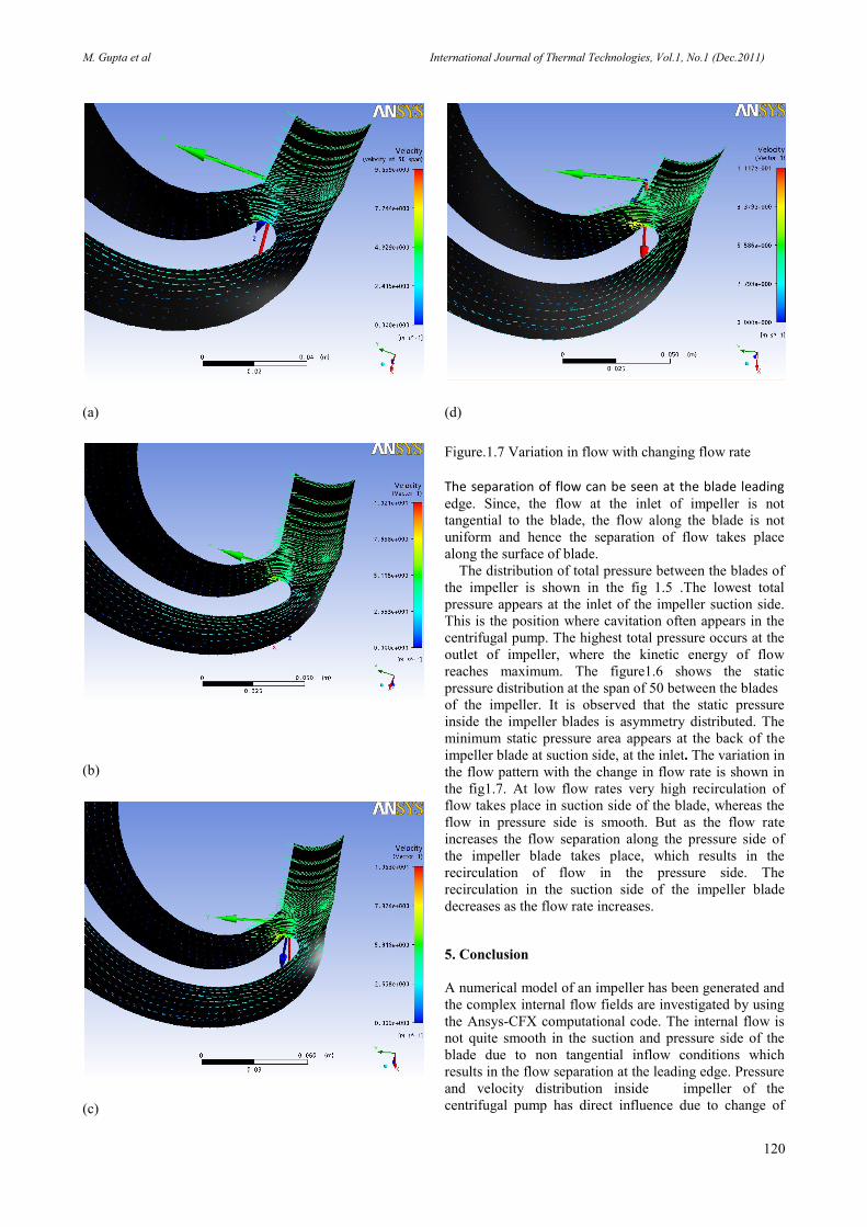
Fig 1.3 shows the distribution of pressure along stream
wise direction at 20 and 50 spans. Pressure increases
gradually along stream wise direction within impeller
M. Gupta et al International Journal of Thermal Technologies, Vol.1, No.1 (Dec.2011)
119
passage and has higher pressure in pressure side than
suction side of the impeller blade. Fig.1.4 shows the
distribution of velocity along stream wise direction at 20
and 50 span.
Fig.1.3. Pressure distribution at 20, 50 span
Fig.1.4. Velocity distribution at 20, 50 span
Figure.1.5. Distribution of total Pressure
Figure1.6. Distribution of static pressure
M. Gupta et al International Journal of Thermal Technologies, Vol.1, No.1 (Dec.2011)
120
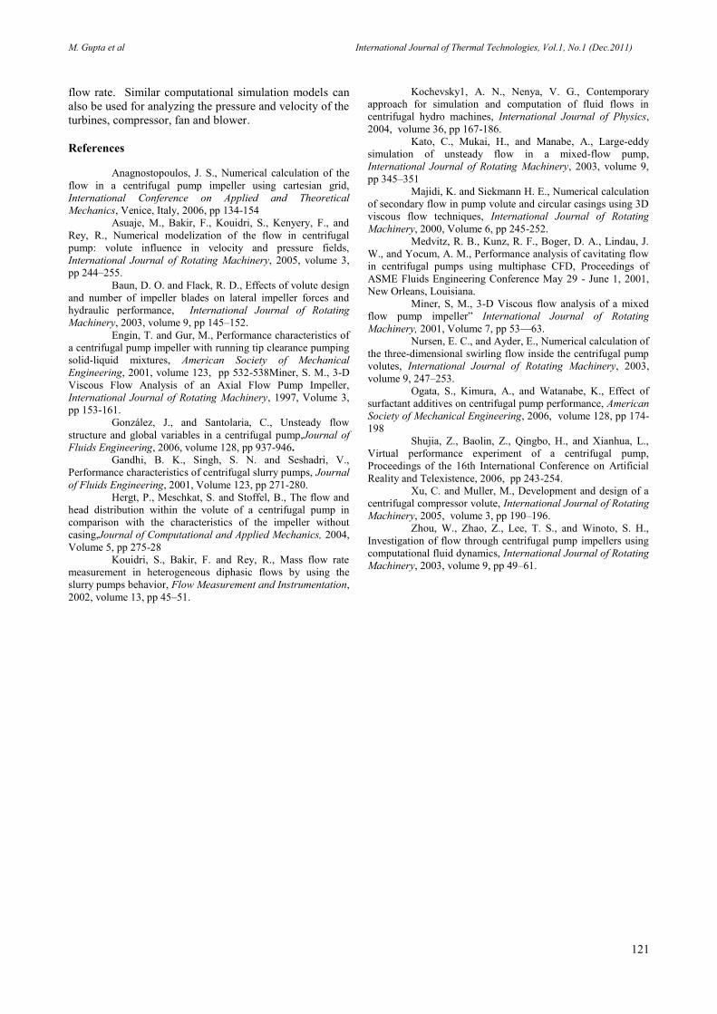
(a)
(b)
(c)
(d)
Figure.1.7 Variation in flow with changing flow rate
The separation of flow can be seen at the blade leading edge. Since, the flow at the inlet of impeller is not
tangential to the blade, the flow along the blade is not
uniform and hence the separation of flow takes place
along the surface of blade.
The distribution of total pressure between the blades of
the impeller is shown in the fig 1.5 .The lowest total
pressure appears at the inlet of the impeller suction side.
This is the position where cavitation often appears in the
centrifugal pump. The highest total pressure occurs at the
outlet of impeller, where the kinetic energy of flow
reaches maximum. The figure1.6 shows the static
pressure distribution at the span of 50 between the blades
of the impeller. It is observed that the static pressure
inside the impeller blades is asymmetry distributed. The
minimum static pressure area appears at the back of the
impeller blade at suction side, at the inlet. The variation in
the flow pattern with the change in flow rate is shown in
the fig1.7. At low flow rates very high recirculation of
flow takes place in suction side of the blade, whereas the
flow in pressure side is smooth. But as the flow rate
increases the flow separation along the pressure side of
the impeller blade takes place, which results in the
recirculation of flow in the pressure side. The
recirculation in the suction side of the impeller blade
decreases as the flow rate increases.
5. Conclusion
A numerical model of an impeller has been generated and
the complex internal flow fields are investigated by using
the Ansys-CFX computational code. The internal flow is
not quite smooth in the suction and pressure side of the
blade due to non tangential inflow conditions which
results in the flow separation at the leading edge. Pressure
and velocity distribution inside impeller of the
centrifugal pump has direct influence due to change of
M. Gupta et al International Journal of Thermal Technologies, Vol.1, No.1 (Dec.2011)
121
flow rate. Similar computational simulation models can
also be used for analyzing the pressure and velocity of the
turbines, compressor, fan and blower.
References
Anagnostopoulos, J. S., Numerical calculation of the
flow in a centrifugal pump impeller using cartesian grid,
International Conference on Applied and Theoretical
Mechanics, Venice, Italy, 2006, pp 134-154
Asuaje, M., Bakir, F., Kouidri, S., Kenyery, F., and
Rey, R., Numerical modelization of the flow in centrifugal
pump: volute influence in velocity and pressure fields,
International Journal of Rotating Machinery, 2005, volume 3,
pp 244–255.
Baun, D. O. and Flack, R. D., Effects of volute design
and number of impeller blades on lateral impeller forces and
hydraulic performance, International Journal of Rotating
Machinery, 2003, volume 9, pp 145–152.
Engin, T. and Gur, M., Performance characteristics of
a centrifugal pump impeller with running tip clearance pumping
solid-liquid mixtures, American Society of Mechanical
Engineering, 2001, volume 123, pp 532-538Miner, S. M., 3-D
Viscous Flow Analysis of an Axial Flow Pump Impeller,
International Journal of Rotating Machinery, 1997, Volume 3,
pp 153-161.
González, J., and Santolaria, C., Unsteady flow
structure and global variables in a centrifugal pump,Journal of
Fluids Engineering, 2006, volume 128, pp 937-946.
Gandhi, B. K., Singh, S. N. and Seshadri, V.,
Performance characteristics of centrifugal slurry pumps, Journal
of Fluids Engineering, 2001, Volume 123, pp 271-280.
Hergt, P., Meschkat, S. and Stoffel, B., The flow and
head distribution within the volute of a centrifugal pump in
comparison with the characteristics of the impeller without
casing,Journal of Computational and Applied Mechanics, 2004,
Volume 5, pp 275-28
Kouidri, S., Bakir, F. and Rey, R., Mass flow rate
measurement in heterogeneous diphasic flows by using the
slurry pumps behavior, Flow Measurement and Instrumentation,
2002, volume 13, pp 45–51.
Kochevsky1, A. N., Nenya, V. G., Contemporary
approach for simulation and computation of fluid flows in
centrifugal hydro machines, International Journal of Physics,
2004, volume 36, pp 167-186.
Kato, C., Mukai, H., and Manabe, A., Large-eddy
simulation of unsteady flow in a mixed-flow pump,
International Journal of Rotating Machinery, 2003, volume 9,
pp 345–351
Majidi, K. and Siekmann H. E., Numerical calculation
of secondary flow in pump volute and circular casings using 3D
viscous flow techniques, International Journal of Rotating
Machinery, 2000, Volume 6, pp 245-252.
Medvitz, R. B., Kunz, R. F., Boger, D. A., Lindau, J.
W., and Yocum, A. M., Performance analysis of cavitating flow
in centrifugal pumps using multiphase CFD, Proceedings of
ASME Fluids Engineering Conference May 29 - June 1, 2001,
New Orleans, Louisiana.
Miner, S, M., 3-D Viscous flow analysis of a mixed
flow pump impeller” International Journal of Rotating
Machinery, 2001, Volume 7, pp 53—63.
Nursen, E. C., and Ayder, E., Numerical calculation of
the three-dimensional swirling flow inside the centrifugal pump
volutes, International Journal of Rotating Machinery, 2003,
volume 9, 247–253.
Ogata, S., Kimura, A., and Watanabe, K., Effect of
surfactant additives on centrifugal pump performance, American
Society of Mechanical Engineering, 2006, volume 128, pp 174-
198
Shujia, Z., Baolin, Z., Qingbo, H., and Xianhua, L.,
Virtual performance experiment of a centrifugal pump,
Proceedings of the 16th International Conference on Artificial
Reality and Telexistence, 2006, pp 243-254.
Xu, C. and Muller, M., Development and design of a
centrifugal compressor volute, International Journal of Rotating
Machinery, 2005, volume 3, pp 190–196.
Zhou, W., Zhao, Z., Lee, T. S., and Winoto, S. H.,
Investigation of flow through centrifugal pump impellers using
computational fluid dynamics, International Journal of Rotating
Machinery, 2003, volume 9, pp 49–61.


![Comparative numerical evaluation for the low velocity ...carbonlett.org/Upload/files/CARBONLETT/[089-095]-09.pdf · 89 Comparative numerical evaluation for the low velocity impact](https://img.pdfslide.net/doc/110x75/5b5207767f8b9a56588cdd53/comparative-numerical-evaluation-for-the-low-velocity-089-095-09pdf-89.jpg)