Embed Size (px)
Citation preview
NUREG-0612 EVALUATION
LIFT OF SPENT FUEL POOL WEIR GATES
San Onofre Nuclear Generating Station Units 2 and 3
February, 1987
83702260007 87021 PDR ADOCK 05000361 p PDR
INTRODUCTION
PURPOSE OF REPORT:
By letter dated December 22, 1980, the NRC requested that SCE review provisions for handling and control of heavy loads at San Onfore Units 2 and 3 with respect to the guidelines of NUREG-0612. SCE submitted several reports to the NRC which provided the complete response concerning NUREG-0612. Specifically, in reports submitted by letters dated July 7, 1981 and April 30, 1982, SCE addressed lifts of the bulkhead or weir gates at either end of the spent fuel pool. The purpose of this report is to address the lift of the two spent fuel pool weir gates at each unit which separates the spent fuel cask storage pool and fuel transfer pool from the spent fuel pool.
San Onofre Units 2 and 3 each have two weir gates located at opposite ends of the spent fuel pool. The gates have dimensions of 3 feet by 29 feet and weigh approximately 4400 lbs.
The lift of the weir gates at both ends of the spent fuel pool is necessary only if maintenance on the gate seals is required; at the time of SCE's initial review of heavy loads it was not yet clear that periodic maintenance of the seals would be necessary. This report is a complete review of the lift of the spent fuel pool weir gates intended to supersede all previous discussion of this particular lift.
CONTROL OF WEIR GATE LIFT: RESPONSE TO NUREG-0612
ITEM 1: Identification of overhead handling systems from which a load drop may result in damage to any system required for plant shutdown or decay heat removal (taking no credit for any interlocks, technical specifications, operating procedures, or detailed structural analysis).
RESPONSE: There are two handling systems of sufficient capacity to be subject to review under the guidelines of NUREG-0612 during the lift of the fuel pool weir gates. The handling systems are the cask handling crane and the new fuel handling crane. A brief description of the cranes is provided below.
Cask Handling Crane: The cask handling crane is located in the fuel handling building above the elevation 63 foot 6 inch floor. The crane trolley has a 125-ton main hoist and 10-ton auxiliary hoist and runs between two bridge girders. The hoist is operated from the cab on one end of the bridge. The crane is used for lifting the spent fuel cask between the shipping-receiving area, the cask decontamination pit, and the cask loading pit. It is also used to lift the spent fuel pool gate at the spent fuel cask handling end of the spent fuel pool for maintenance purposes. The lift of the pool gate represents a potential interaction with spent fuel in the spent fuel pool.
-1 -
New Fuel Handling Crane: The new fuel handling crane is a single girder underhung bridge crane spanning the new fuel storage area. The crane is equipped with a mechanically operated interlocking device that allows the bridge to be interlocked with a monorail section. The 5-ton capacity hoist traveling on the monorail section can travel over the edge of the spent fuel pool and is used to lift the spent fuel pool gate at this end of the pool. This lift represents a potential interaction with spent fuel.
ITEM 2: Justify the exclusion of any overhead handling system from this report by verifying that there is sufficient . . .
RESPONSE: Neither of the overhead handling systems involved in the lifts of the weir gates are excluded from this report.
ITEM 3: Provide an evaluation concerning compliance of the load handling systems used in the weir gate lifts with the guidelines of NUREG-0612, section 5.1.1. The following specific information should be included in the reply.
a. Drawings or sketches sufficient to clearly identify the location of safe load paths, spent fuel, and safety-related equipment.
b. A discussion of measures taken to ensure that load-handling operations remain within safe load paths, including procedures, if any, for deviation from these paths.
RESPONSE:
Guideline 1 - Safe Load Paths
Figure 1 provides the general arrangement of the pools and storage racks*. The safe load path for the weir gate lift requires three rows of storage rack locations to be vacant at each end of the spent fuel pool.
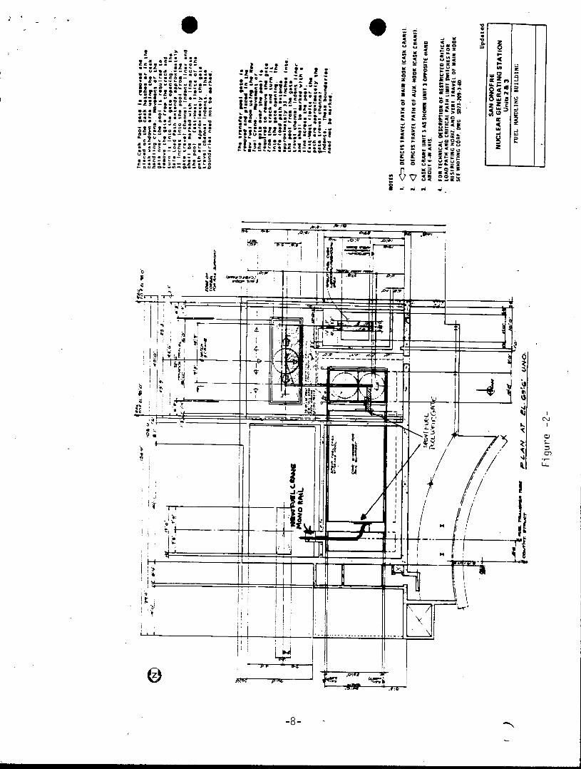
Figure 2 (previously submitted by letter dated July 7, 1981) has been revised to show specific safe load paths for installation and removal of the cask pool and transfer pool gates. The previous paths were expanded to allow movement of the gates at the pool edge (to remove them from the track) and into the gate opening. The East-West boundary will be marked across the pool. All Spent Fuel Rack locations under the Gate Removal Load Path will be vacant of Spent Fuel. This path will be defined by the EAST-WEST Boundary line and the edges of the gate travel channel indents.
-2-
Guideline 2 - Load Handling Procedures
Station Procedures detail rigging requirements including a minimum load rating for each component, periodic testing requirements, prior to use inspection requirements, a detailed "step-by-step" sequence, safe load path, and other special precautions. Attachment 1 to this report provides a summary of the rigging typically used to install and remove gates. The specific procedures controlling this lift are as follows:
(1) Procedure, S0123-I-1.13, "Cranes, Rigging and Lifting Controls",
(2) Procedure, S023-I-3.32, "Cask Handling Crane'Checkout and Operation",
(3) Procedure, S023-I-3.21, "New Fuel Crane Checkout and Operation",
(4) Procedure, S023-1-6.157, "Spent Fuel Pool Gate Removal/Reinstallation".
Guideline 3 - Crane Operator Training
The previously approved program for crane operator training is unchanged as a result of this re-evaluation. (Refer to letter dated August 27, 1984 from George W. Knighton (NRC) to K. P. Baskin (SCE); Subject: Safety Evaluation Report Relating to Control of Heavy Loads at SONGS 2 and 3).
Guideline 4 - Special Lifting Devices
This guideline is not applicable to movement of the gates. The rigging components used are controlled in accordance with Guideline 5.
Guideline 5 - Lifting Devices (Not Specially Designed)
All lifting components will be installed and used in accordance with ANSI 830.9-1971: Slings. If this standard should be revised, the updated standard would be complied with.
The spent fuel pool gates weigh approximately 4,400 pounds. When lifting a gate, all components in a single load train will have a load rating of at least 10,000 lbs. The components in a double load train, specifically the shackles attaching rigging to the gate will have a load rating of at least 9500 lbs. These minimum load ratings assure that at least a two to one design safety factor exists when lifting a gate.
Attachment 1 provides a sketch of rigging typically used to lift the weir gate. Current Station Procedures for the control of the rigging components are discussed in Guideline 2.
-3-
Guideline 5 (continued)
With regard to the weir gate lift which utilizes slings, plant procedures will require that sling selection, use, and marking will be in accordance with ANSI 830.9 and NUREG-0612 Section 5.1.1.(5). Rated loads identified for each sling will be based on the sum of the static and maximum dynamic load. Dynamic loads have been determined in accordance with CMAA-70 specifications, I.e., the dynamic load "shall be taken as 1/2% of the load per foot per minute of hoisting speed." The maximum hoist speed of the cask handling crane and the new fuel crane at no load is 30 feet per minute. This results in a maximum dynamic load of 15% of the lifted load. Plant procedures specify that sling selection be based on 200% of the lifted load (which is in excess of the 115% specified for NUREG 0612.)
Guideline 6 - Cranes (Inspection, Testing and Maintenance)
The New Fuel Handling Crane (used to move the transfer pool gate) and Cask Handlng Crane (used to move the cask pool gate) will be inspected, tested, and maintained in accordance with Chapter 2-2 of the ANSI 830.2-1976, "Overhead and Gantry Cranes."
Cask Handling Crane: The cask handling crane is located in the fuel handling building. The crane trolley has a 125-ton main hoist and 10-ton auxiliary hoist and runs between two bridge girders. The hoists are operated from the cab on one end of the bridge. The crane is used for lifting the spent fuel cask between the cask loading hatch, the cask pool, and the cask washdown area. It is also used to lift the gate between the cask pool and the spent fuel pool for maintenance purposes. Neither of these loads is carried directly over equipment required for safe shutdown or for removal of decay heat. The cask pool is separated from the spent fuel storage pool by a 4 ft. thick reinforced concrete wall, and the water contents of the two pools can be isolated by the bulkhead gate located on the spent fuel pool side.
The cask handling crane 10 ton or 125 ton hoist is used to move the bulkhead gate at the cask handling end of the spent fuel pool. Movement of this gate at the edge of the spent fuel pool represents a potential interaction with spent fuel in the spent fuel pool; however, at no time will the gate be moved outside of the designated safe load path. The cask handling crane trolley is at its extreme northern position when moving the gate inside the spent fuel pool. The cask handling crane is used to lift the gate only a few inches while the gate is in the spent fuel pool to provide clearance for passage of the gate through the gate opening into the cask pool. Prior to this short lift and horizontal translation of the gate into the cask pool, a small off-set pull (into the spent fuel pool) is necessary to disengage the gate from the four (4) inch angle track and rotate the gate 900 into the gate opening. After horizontal translation of the gate into the cask pool, the gate is moved away from the gate opening before the gate is lifted out of the cask pool. After lifting out of the cask pool, the gate is moved away from the spent fuel pool to the cask hatch area for maintenance.
-4-
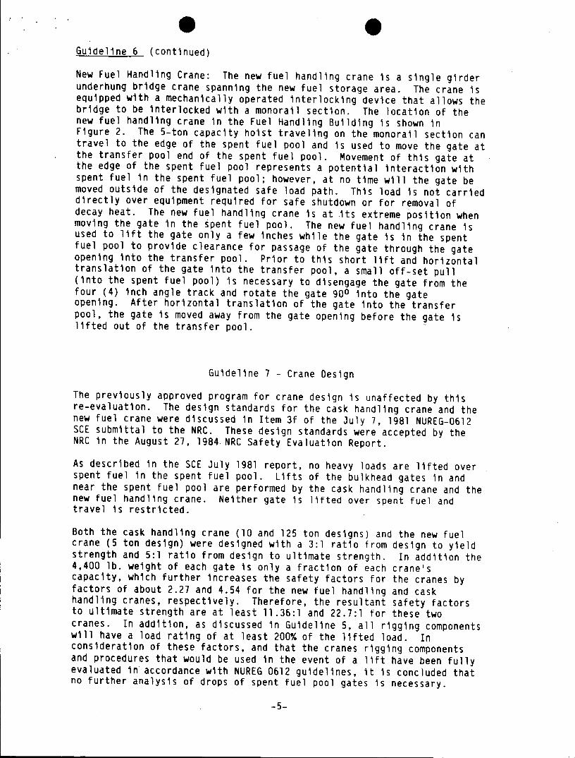
Guideline 6 (continued)
New Fuel Handling Crane: The new fuel handling crane is a single girder underhung bridge crane spanning the new fuel storage area. The crane is equipped with a mechanically operated interlocking device that allows the bridge to be interlocked with a monorail section. The location of the new fuel handling crane in the Fuel Handling Building is shown in Figure 2. The 5-ton capacity hoist traveling on the monorail section can travel to the edge of the spent fuel pool and is used to move the gate at the transfer pool end of the spent fuel pool. Movement of this gate at the edge of the spent fuel pool represents a potential interaction with spent fuel in the spent fuel pool; however, at no time will the gate be moved outside of the designated safe load path. This load is not carried directly over equipment required for safe shutdown or for removal of decay heat. The new fuel handling crane is at its extreme position when moving the gate in the spent fuel pool. The new fuel handling crane is used to lift the gate only a few inches while the gate is in the spent fuel pool to provide clearance for passage of the gate through the gate opening into the transfer pool. Prior to this short lift and horizontal translation of the gate into the transfer pool, a small off-set pull (into the spent fuel pool) is necessary to disengage the gate from the four (4) inch angle track and rotate the gate 900 into the gate opening. After horizontal translation of the gate into the transfer pool, the gate is moved away from the gate opening before the gate is lifted out of the transfer pool.
Guideline 7 - Crane Design
The previously approved program for crane design is unaffected by this re-evaluation. The design standards for the cask handling crane and the new fuel crane were discussed in Item 3f of the July 7, 1981 NUREG-0612 SCE submittal to the NRC. These design standards were accepted by the NRC in the August 27, 1984.NRC Safety Evaluation Report.
As described in the SCE July 1981 report, no heavy loads are lifted over spent fuel in the spent fuel pool. Lifts of the bulkhead gates in and near the spent fuel pool are performed by the cask handling crane and the new fuel handling crane. Neither gate is lifted over spent fuel and travel is restricted.
Both the cask handling crane (10 and 125 ton designs) and the new fuel crane (5 ton design) were designed with a 3:1 ratio from design to yield strength and 5:1 ratio from design to ultimate strength. In addition the 4,400 lb. weight of each gate is only a fraction of each crane's capacity, which further increases the safety factors for the cranes by factors of about 2.27 and 4.54 for the new fuel handling and cask handling cranes, respectively. Therefore, the resultant safety factors to ultimate strength are at least 11.36:1 and 22.7:1 for these two cranes. In addition, as discussed in Guideline 5, all rigging components will have a load rating of at least 200% of the lifted load. In consideration of these factors, and that the cranes rigging components and procedures that would be used in the event of a lift have been fully evaluated in accordance with NUREG 0612 guidelines, it is concluded that no further analysis of drops of spent fuel pool gates is necessary.
-5-
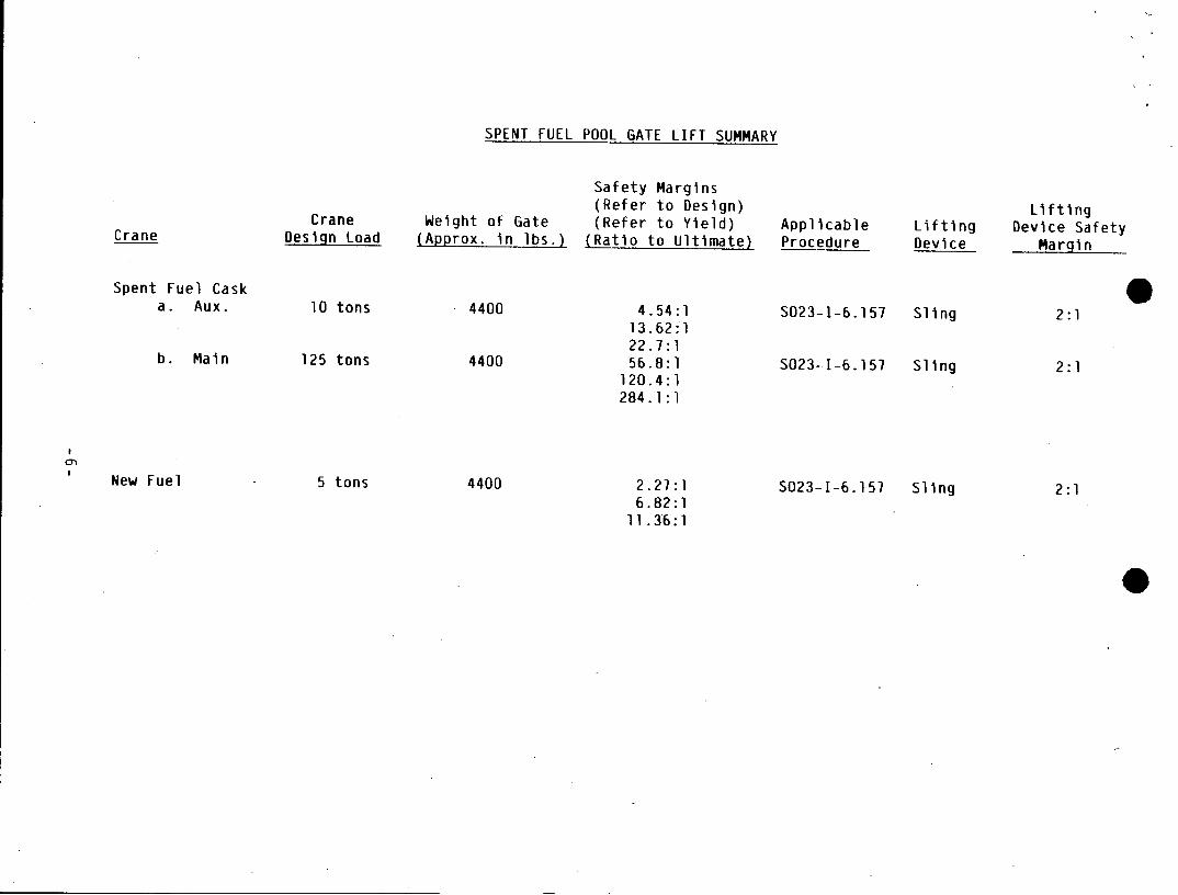
SPENT FUEL POOL GATE LIFT SUMMARY
Safety Margins (Refer to Design) Lifting
Crane Weight of Gate (Refer to Yield) Applicable Lifting Device Safety Crane Design Load (Approx. in lbs.) (Ratio to Ultimate) Procedure Device Margin
Spent Fuel Cask a. Aux. 10 tons 4400 4.54:1 S023-1-6.157 Sling 2:1
13.62:1 22.7:1
b. Main 125 tons 4400 56.8:1 S023-I-6.157 Sling 2:1 120.4:1 284.1:1
New Fuel 5 tons 4400 2.27:1 S023-1-6.157 Sling 2:1 6.82:1
11 .36:1
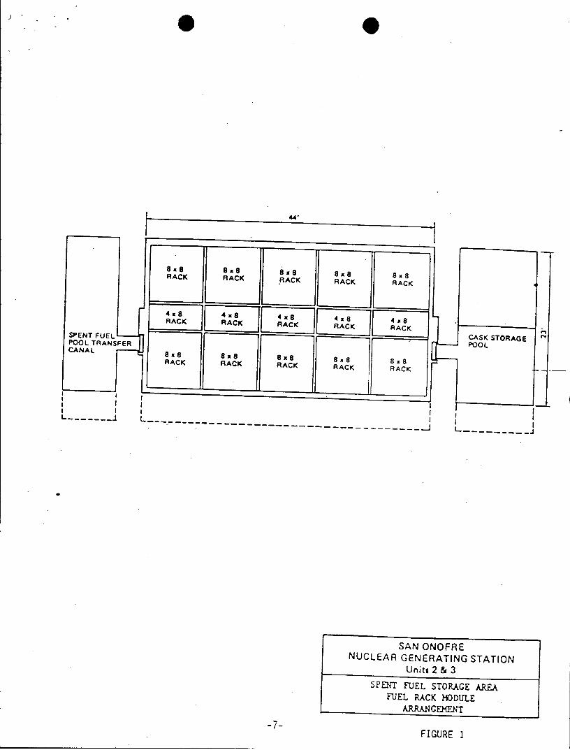
88 8 8 8x8 8 8 x8 RACK RACK RACK RACK RACK
RACK RACK AAK4x 4RACK
SPENT FUEL CASK STORAGE POOL TRANSFER POOL CANAL 8 8
RACK RACK RACK RACK RACK
I I I
SAN ONOFAE
N 0 '
NUCLEAR GENERATN TTO Units 2 & 3
SPENT FUEL STORAGE AREA -EL RACK HODULE
A RRANCEMENT
-7FIGURE 1
Sz CE C 0 0 z* 0
ev*- CV " V-. -e0%
0 O-C ~.-I * 0 :z ael : .. ** * - * .. .1 CC -C~ .C C C -~
!~~erceZ ~ M C* &CC Cea-a s~~.Ja.I
CA fC 2 SUC-CeC ~ ~ ro 26C UC
.iO S~ * -- ec..-. . **~.
~CCC~ -ua~.. -** *CCCSOC-h
CC CUC CC;CC C ) CCC U - -.
*O * - - hCCC CC..U. ~ 4 *6
* CC -CG aoL 3C L CC CUC~..C - S~ ,4 U4l
L4 . -- S
US - C - ~ CU C
UCCCCC- C C cc
C-------------
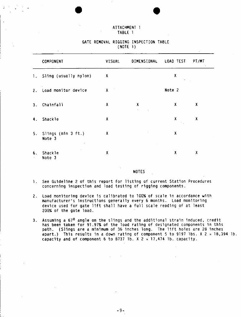
ATTACHMENT 1 TABLE 1
GATE REMOVAL RIGGING INSPECTION TABLE (NOTE 1)
COMPONENT VISUAL DIMENSIONAL LOAD TEST PT/MT
1. Sling (usually nylon) X x
2. Load monitor device X Note 2
3. Chainfall X X X X
4. Shackle X X X
5. Slings (min 3 ft.) X x Note 3
6. Shackle X X X Note 3
NOTES
1. See Guideline 2 of this report for listing of current Station Procedures concerning inspection and load testing of rigging components.
2. Load monitoring device is calibrated to 100% of scale in accordance with manufacturer's instructions generally every 6 months. Load monitoring device used for gate lift shall have a full scale reading of at least 200% of the gate load.
3. Assuming a 670 angle on the slings and the additional strain induced, credit has been taken for 91.97% of the load rating of designated components in this path. (Slings are a minimum of 36 inches long. The lift holes are 28 inches apart.) This results in a down rating of component 5 to 9197 lbs. X 2 18,394 lb. capacity and of component 6 to 8737 lb. X 2 = 17,474 lb. capacity.
-9-
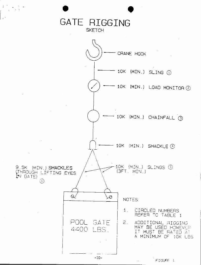
GATE RIGGING SKETCH
CRANE HOOK
10K (MIN.) SLING 0
/ - 10K (MIN.) LOAD MONITOR®
10K (MIN.) CHAINFALL ®
10K (MIN.) SHACKLE®
9.5K (MIN.)SHACKLES 10K (MIN.) SLINGS 05 'THROUGH LIFTING EYES (3FT MIN.) LN GATE)
NOTES.
1. CIRCLED NUMBERS REFER TO TABLE I
0OL GATE 2. ADDITIONAL RIGGING MAY BE USED HOWEVE" 4400 LBS . IT MUST BE RATED AT A MINIMUM OF 10K LB
-10- FI G F- I
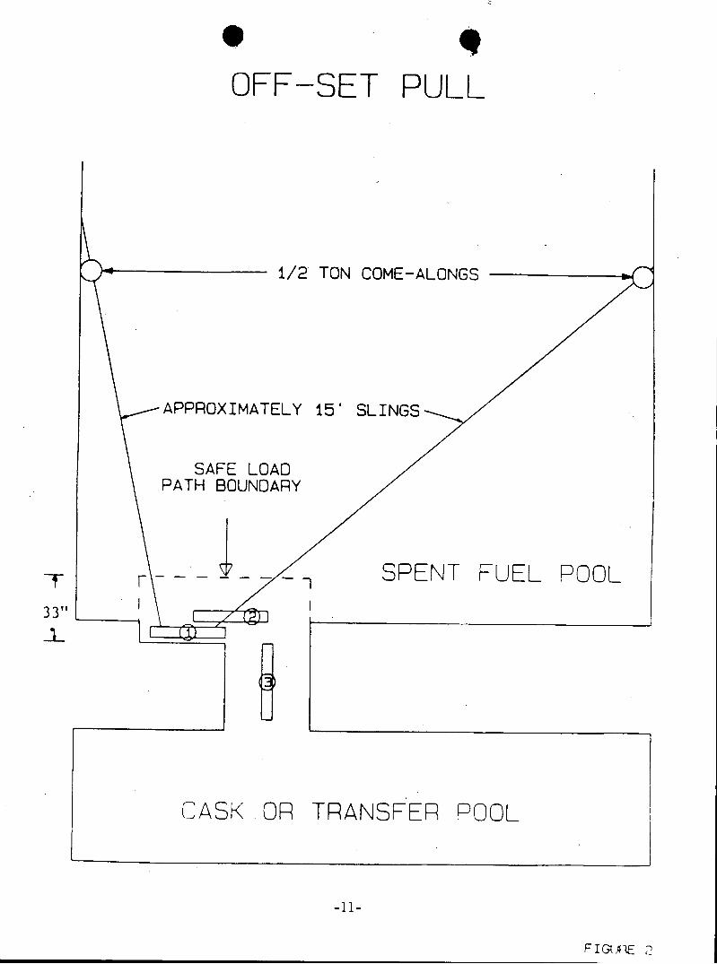
OFF-SET PULL
1/2 TON COME-ALONGS
APPROXIMATELY 15' SLINGS
SAFE LOAD PATH BOUNDARY
T-- SPENT FUEL POOL
331
CASK OR TRANSFER POOL
-11-