Embed Size (px)
Citation preview
This content has been downloaded from IOPscience. Please scroll down to see the full text.
Download details:
IP Address: 138.253.100.121
This content was downloaded on 27/01/2014 at 14:00
Please note that terms and conditions apply.
NUV femtosecond laser inscription of volume Bragg gratings in poly(methyl)methacrylate with
linear and circular polarizations
View the table of contents for this issue, or go to the journal homepage for more
2013 Laser Phys. 23 126004
(http://iopscience.iop.org/1555-6611/23/12/126004)
Home Search Collections Journals About Contact us My IOPscience

IOP PUBLISHING LASER PHYSICS
Laser Phys. 23 (2013) 126004 (10pp) doi:10.1088/1054-660X/23/12/126004
NUV femtosecond laser inscriptionof volume Bragg gratings inpoly(methyl)methacrylate with linearand circular polarizations
L Ye1, W Perrie1, O J Allegre1, Y Jin1, Z Kuang1, P J Scully2, E Fearon1,D Eckford1, S P Edwardson1 and G Dearden1
1 Laser Group, School of Engineering, University of Liverpool, L69 3GQ, UK2 The Photon Science Institute, The University of Manchester, M13 9PL, UK
E-mail: [email protected]
Received 20 August 2013Accepted for publication 25 October 2013Published 19 November 2013Online at stacks.iop.org/LP/23/126004
AbstractLarge, high efficiency, volume Bragg gratings with dimensions of 5 mm× 5 mm and thicknessbetween 1 and 7 mm with 20 µm pitch have been inscribed in poly(methyl)methacrylate(PMMA) with 180 fs, 387 nm parallel beams using both linear and circular polarizations.Linear polarization (perpendicular to the scan direction) produced the highest refractive indexcontrast, while circular polarization produced the lowest. The measured first-order diffractionefficiency with grating thickness L agrees well with theoretical expectations, and reached amaximum of 94% near L = 4 mm, the highest yet observed in pure PMMA. The source of thevariation in refractive index contrast was investigated, and it was found to be due to thepolarization-dependent nonlinear filamentation, the first such observation in a pure polymer.
(Some figures may appear in colour only in the online journal)
1. Introduction
Volume Bragg gratings (VBGs) are used in a widerange of interesting applications, such as astronomicalspectroscopy, ultrafast laser compressors and wavelengthdivision multiplexing [1], wavelength stabilization of highpower laser diodes [2], and narrowband filters for Ramanspectroscopy [3]. Further, chirped VBGs have been used inthe stretching and compression of ultrafast laser pulses in fibrelaser chirped pulse amplification (CPA) systems, eliminatingthe dispersion mismatch of the stretcher/compressor [4].VBGs are generally produced holographically in photosen-sitive materials such as dichromated gelatine (DCG) filmstypically 10–30 µm thick with refractive index (RI) mod-ulation 1n ∼ 0.02–0.1 [5] or photothermorefractive (PTR)glass, where modified thickness can be several millimetreswith 1n ∼ 0.001 [6]. Such gratings are remarkably stable,
and in the case of PTR material can handle high averagelaser powers exceeding 100 W with damage thresholds F ∼10 J cm−2 [7]. Careful design can result in devices withhigh diffraction efficiency close to unity combined with linedensities >1000 lines mm−1.
Femtosecond laser inscription, initiated by multi-photonabsorption, has extended the field of microstructured opticalmaterials to almost all transparent dielectrics, includingglasses [8–13] and polymers [14–25]. Thanks to their ease ofmanufacture and low cost, polymers are attractive substratesfor the fabrication of photonic components such as transientoptical memory [14], photonic crystals [15], 2D and 3Dwaveguides [16, 17], 3D microchannels [18], splitters [19],and VBGs [20]. In the latter case, holographic exposure ofazodye-doped PMMA with NIR, 150 fs pulses yielded 0.3 mmdiameter VBGs with a first-order Bragg diffraction efficiency(DE) η1 ∼ 90% and 200 lines mm−1. However, inscription
11054-660X/13/126004+10$33.00 c© 2013 Astro Ltd Printed in the UK & the USA
Laser Phys. 23 (2013) 126004 L Ye et al
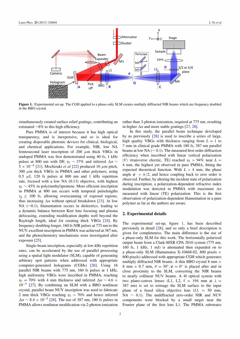
Figure 1. Experimental set-up. The CGH applied to a phase-only SLM creates multiply diffracted NIR beams which are frequency doubledin the BBO crystal.
simultaneously created surface relief gratings, contributing anestimated ∼8% to this high efficiency.
Pure PMMA is of interest because it has high opticaltransparency, and is inexpensive, and so is ideal forcreating disposable photonic devices for clinical, biological,and chemical applications. For example, NIR, low NAfemtosecond laser inscription of 200 µm thick VBGs inundoped PMMA was first demonstrated using 40 fs, 1 kHzpulses at 800 nm with DE η1 ∼ 37% and inferred 1n ∼5 × 10⁻⁴ [21]. Mochizuki et al [22] produced 10 µm pitch,300 µm thick VBGs in PMMA and other polymers, using0.5 µJ, 120 fs pulses at 800 nm and 1 kHz repetitionrate, focused with a low NA (0.13) objective, with highestη1 ∼ 45% in poly(methyl)pentene. More efficient inscriptionin PMMA at 800 nm occurs with temporal pulselengthsτp ≤ 100 fs, allowing overscanning of exposed regions,thus increasing 1n without optical breakdown [23]. At lowNA (∼0.1), filamentation occurs in dielectrics, leading toa dynamic balance between Kerr lens focusing and plasmadefocusing, extending modification depths well beyond theRayleigh length, ideal for creating thick VBGs [24]. Byfrequency doubling longer, 160 fs NIR pulses at 775 nm to theNUV, excellent inscription in PMMA was achieved at 387 nm,and the photochemistry mechanisms were investigated afterexposure [25].
Single-beam inscription, especially at low kHz repetitionrates, can be accelerated by the use of parallel processingusing a spatial light modulator (SLM), capable of generatingarbitrary spot patterns when addressed with appropriatecomputer-generated holograms (CGHs) [26]. Using 16parallel NIR beams with 775 nm, 160 fs pulses at 1 kHz,high uniformity VBGs were inscribed in PMMA, reachingη1 = 70% with 4 mm thickness and inferred 1n ∼ 4.6 ×10⁻⁵ [27]. By combining an SLM with a BBO nonlinearcrystal, parallel beam NUV inscription was used to fabricate2 mm thick VBGs reaching η1 > 70% and hence inferred1n ∼ 8.4 × 10⁻⁵ [28]. The use of 387 nm, 180 fs pulses inPMMA allows nonlinear modification via 2-photon ionization
rather than 3-photon ionization, required at 775 nm, resultingin higher 1n and more stable gratings [27, 28].
In this study, the parallel beam technique developedby us previously [28] is used to inscribe a series of large,high quality VBGs with thickness ranging from L = 1 to7 mm in clinical grade PMMA with 180 fs, 387 nm parallelbeams at low NA (∼ 0.1). The measured first-order diffractionefficiency when inscribed with linear vertical polarization|V〉 (transverse electric, TE) reached η1 > 94% near L =4 mm, the highest yet observed in pure PMMA, fitting theexpected theoretical function. With L > 4 mm, the phaseangle φ > π/2, and hence coupling back to zero order isobserved. Further, by altering the incident state of polarizationduring inscription, a polarization-dependent refractive indexmodulation was detected in PMMA with maximum 1nmeasured with linear (TE) polarization. This is the firstobservation of polarization-dependent filamentation in a purepolymer as far as the authors are aware.
2. Experimental details
The experimental set-up, figure 1, has been describedpreviously in detail [28], and so only a brief description isgiven for completeness. The main difference is the use ofa phase-only SLM for this work. The horizontally polarizedoutput beam from a Clark-MXR CPA 2010 system (775 nm,160 fs, 1 kHz, 1 mJ) is attenuated then expanded on toa phase-only SLM (Hamamatsu X-10468-02, 800 pixels ×600 pixels) addressed with appropriate CGH which generatesmultiply diffracted NIR beams. A thin BBO crystal 8 mm ×8 mm × 0.7 mm, θ = 30◦, φ = 0◦ is placed after and inclose proximity to the SLM, converting the NIR beamsto nearly collinear NUV beams. A 4f optical system withtwo plano-convex lenses (L1, L2, f = 194 mm at λ =387 nm) is set to reimage the SLM surface to the inputplane of a fused silica objective lens (f.l. = 50 mm,NA ∼ 0.1). The undiffracted zero-order NIR and NUVcomponents were blocked by a small target near theFourier plane of the first lens L1. The PMMA substrates
2
Laser Phys. 23 (2013) 126004 L Ye et al
(a)
(b)
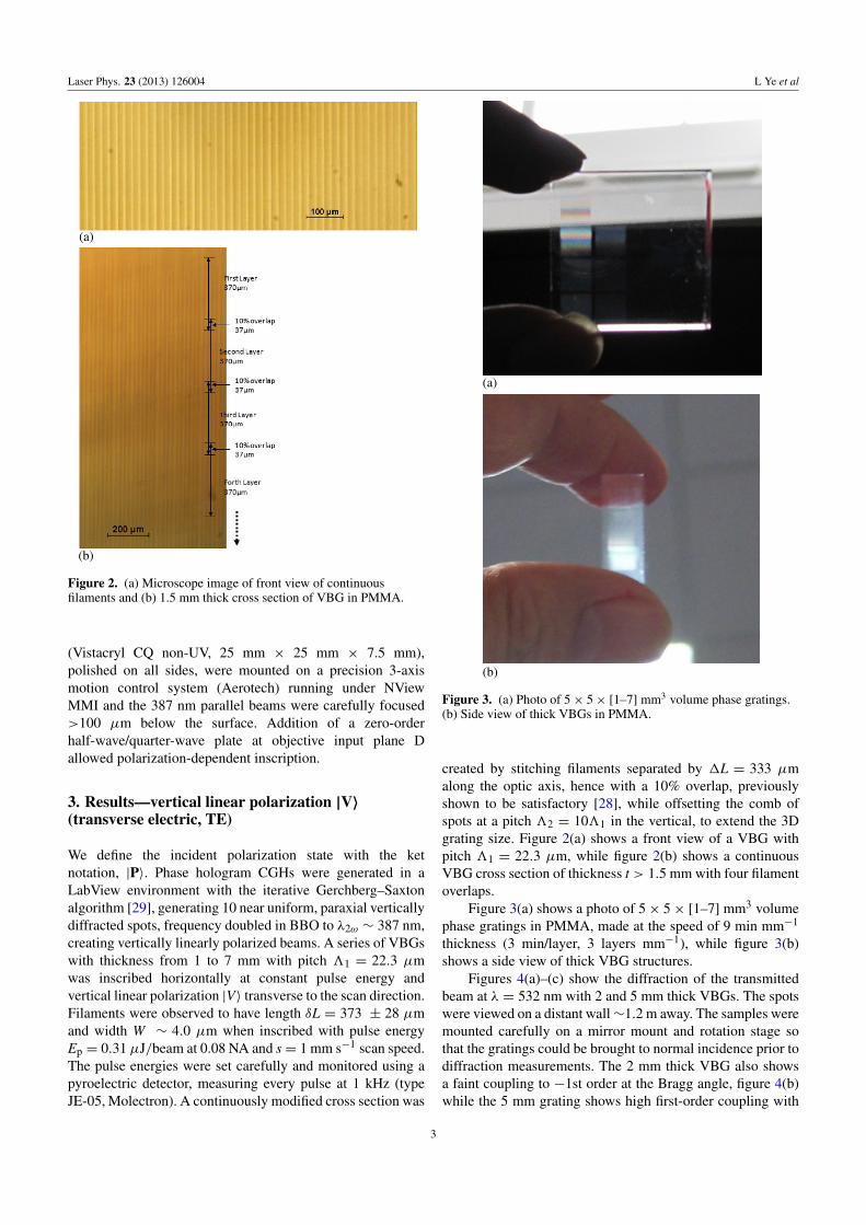
Figure 2. (a) Microscope image of front view of continuousfilaments and (b) 1.5 mm thick cross section of VBG in PMMA.
(Vistacryl CQ non-UV, 25 mm × 25 mm × 7.5 mm),polished on all sides, were mounted on a precision 3-axismotion control system (Aerotech) running under NViewMMI and the 387 nm parallel beams were carefully focused>100 µm below the surface. Addition of a zero-orderhalf-wave/quarter-wave plate at objective input plane Dallowed polarization-dependent inscription.
3. Results—vertical linear polarization |V〉
(transverse electric, TE)
We define the incident polarization state with the ketnotation, |P〉. Phase hologram CGHs were generated in aLabView environment with the iterative Gerchberg–Saxtonalgorithm [29], generating 10 near uniform, paraxial verticallydiffracted spots, frequency doubled in BBO to λ2ω ∼ 387 nm,creating vertically linearly polarized beams. A series of VBGswith thickness from 1 to 7 mm with pitch 31 = 22.3 µmwas inscribed horizontally at constant pulse energy andvertical linear polarization |V〉 transverse to the scan direction.Filaments were observed to have length δL = 373 ± 28 µmand width W ∼ 4.0 µm when inscribed with pulse energyEp = 0.31 µJ/beam at 0.08 NA and s = 1 mm s−1 scan speed.The pulse energies were set carefully and monitored using apyroelectric detector, measuring every pulse at 1 kHz (typeJE-05, Molectron). A continuously modified cross section was
(a)
(b)
Figure 3. (a) Photo of 5× 5× [1–7] mm3 volume phase gratings.(b) Side view of thick VBGs in PMMA.
created by stitching filaments separated by 1L = 333 µmalong the optic axis, hence with a 10% overlap, previouslyshown to be satisfactory [28], while offsetting the comb ofspots at a pitch 32 = 1031 in the vertical, to extend the 3Dgrating size. Figure 2(a) shows a front view of a VBG withpitch 31 = 22.3 µm, while figure 2(b) shows a continuousVBG cross section of thickness t > 1.5 mm with four filamentoverlaps.
Figure 3(a) shows a photo of 5× 5× [1–7] mm3 volumephase gratings in PMMA, made at the speed of 9 min mm−1
thickness (3 min/layer, 3 layers mm−1), while figure 3(b)shows a side view of thick VBG structures.
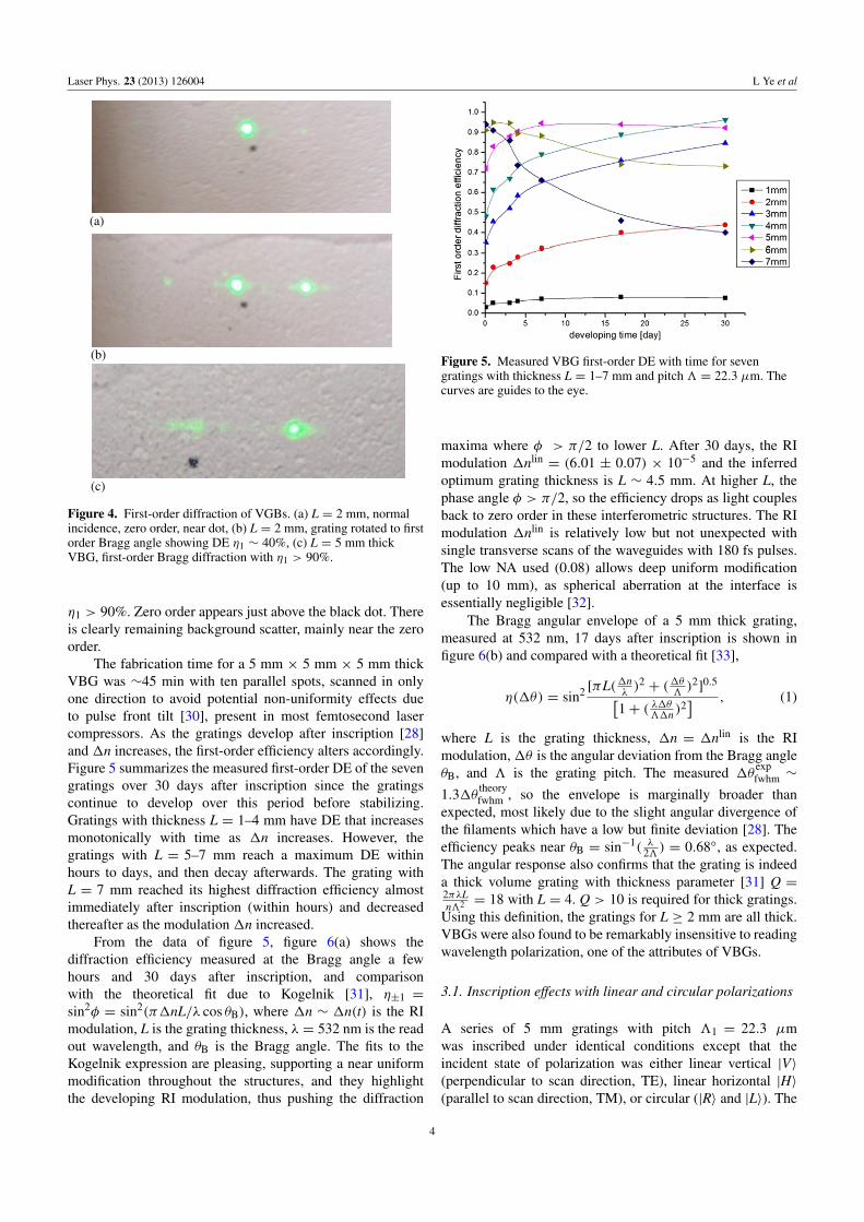
Figures 4(a)–(c) show the diffraction of the transmittedbeam at λ = 532 nm with 2 and 5 mm thick VBGs. The spotswere viewed on a distant wall∼1.2 m away. The samples weremounted carefully on a mirror mount and rotation stage sothat the gratings could be brought to normal incidence prior todiffraction measurements. The 2 mm thick VBG also showsa faint coupling to −1st order at the Bragg angle, figure 4(b)while the 5 mm grating shows high first-order coupling with
3
Laser Phys. 23 (2013) 126004 L Ye et al
(a)
(b)
(c)
Figure 4. First-order diffraction of VGBs. (a) L = 2 mm, normalincidence, zero order, near dot, (b) L = 2 mm, grating rotated to firstorder Bragg angle showing DE η1 ∼ 40%, (c) L = 5 mm thickVBG, first-order Bragg diffraction with η1 > 90%.
η1 > 90%. Zero order appears just above the black dot. Thereis clearly remaining background scatter, mainly near the zeroorder.
The fabrication time for a 5 mm × 5 mm × 5 mm thickVBG was ∼45 min with ten parallel spots, scanned in onlyone direction to avoid potential non-uniformity effects dueto pulse front tilt [30], present in most femtosecond lasercompressors. As the gratings develop after inscription [28]and 1n increases, the first-order efficiency alters accordingly.Figure 5 summarizes the measured first-order DE of the sevengratings over 30 days after inscription since the gratingscontinue to develop over this period before stabilizing.Gratings with thickness L = 1–4 mm have DE that increasesmonotonically with time as 1n increases. However, thegratings with L = 5–7 mm reach a maximum DE withinhours to days, and then decay afterwards. The grating withL = 7 mm reached its highest diffraction efficiency almostimmediately after inscription (within hours) and decreasedthereafter as the modulation 1n increased.
From the data of figure 5, figure 6(a) shows thediffraction efficiency measured at the Bragg angle a fewhours and 30 days after inscription, and comparisonwith the theoretical fit due to Kogelnik [31], η±1 =
sin2φ = sin2(π1nL/λ cos θB), where 1n ∼ 1n(t) is the RImodulation, L is the grating thickness, λ = 532 nm is the readout wavelength, and θB is the Bragg angle. The fits to theKogelnik expression are pleasing, supporting a near uniformmodification throughout the structures, and they highlightthe developing RI modulation, thus pushing the diffraction
Figure 5. Measured VBG first-order DE with time for sevengratings with thickness L = 1–7 mm and pitch 3 = 22.3 µm. Thecurves are guides to the eye.
maxima where φ > π/2 to lower L. After 30 days, the RImodulation 1nlin
= (6.01 ± 0.07) × 10−5 and the inferredoptimum grating thickness is L ∼ 4.5 mm. At higher L, thephase angle φ > π/2, so the efficiency drops as light couplesback to zero order in these interferometric structures. The RImodulation 1nlin is relatively low but not unexpected withsingle transverse scans of the waveguides with 180 fs pulses.The low NA used (0.08) allows deep uniform modification(up to 10 mm), as spherical aberration at the interface isessentially negligible [32].
The Bragg angular envelope of a 5 mm thick grating,measured at 532 nm, 17 days after inscription is shown infigure 6(b) and compared with a theoretical fit [33],
η(1θ) = sin2 [πL(1nλ)2 + (1θ
3)2]0.5[
1+ ( λ1θ31n )
2] , (1)
where L is the grating thickness, 1n = 1nlin is the RImodulation,1θ is the angular deviation from the Bragg angleθB, and 3 is the grating pitch. The measured 1θ
expfwhm ∼
1.31θ theoryfwhm , so the envelope is marginally broader than
expected, most likely due to the slight angular divergence ofthe filaments which have a low but finite deviation [28]. Theefficiency peaks near θB = sin−1( λ23 ) = 0.68◦, as expected.The angular response also confirms that the grating is indeeda thick volume grating with thickness parameter [31] Q =2πλLn32 = 18 with L = 4. Q > 10 is required for thick gratings.
Using this definition, the gratings for L ≥ 2 mm are all thick.VBGs were also found to be remarkably insensitive to readingwavelength polarization, one of the attributes of VBGs.
3.1. Inscription effects with linear and circular polarizations
A series of 5 mm gratings with pitch 31 = 22.3 µmwas inscribed under identical conditions except that theincident state of polarization was either linear vertical |V〉(perpendicular to scan direction, TE), linear horizontal |H〉(parallel to scan direction, TM), or circular (|R〉 and |L〉). The
4

Laser Phys. 23 (2013) 126004 L Ye et al
(a)
(b)
Figure 6. (a) Top: measured first-order DE of seven gratings, a fewhours and 30 days after inscription and comparison with theory(solid lines) η1 = sin2(φ), where 1n = 3.1× 10⁻⁵ and 6.0× 10⁻⁵
respectively. (b) Bottom: measured Bragg angular envelope at532 nm of a 4 mm thick, 3 = 22.3 µm pitch VBG and comparisonwith theoretical fit [33].
polarization was altered using either a zero-order half-wave(|V〉, |H〉) or quarter-wave (|R〉, |L〉) plate, inserted just aheadof the objective. A clear polarization-dependent inscriptionwas observed. First-order DE was highest with verticalpolarization |V〉 (TE), then linear horizontal |H〉 (TM), andfinally circular polarization (|R〉 and |L〉). As expected fromsymmetry, the first-order diffraction efficiency η1(|R〉) =η1(|L〉) within experimental error.
Table 1 summarizes the measured first-order Braggefficiencies, nine days after inscription. Linear polarizationstates clearly couple more strongly to the material. Errorsindicate 1σ . While η1(|V〉) − η1(|H〉) ∼ 5%, the highestdifference η1(|V〉)−η1(|R〉) ∼ 8%, corresponding to δ(1n) =6% and 9% respectively. The total pulse energy wasmonitored carefully throughout the inscription of the sets offour VBGs and maximum variation in pulse energy 1Ep
Ep=
0.02 µJ3.12 µJ = 0.64%, where Ep is the total pulse energy for tenspots.
Figure 7. Measured ratio of first-order diffraction efficienciesη1(|V〉)/η1(|R〉) with time.
Table 1. First-order diffraction efficiencies nine days afterinscription with different polarizations.
Polarization η1 (L = 5 mm) Inferred 1n
|V〉 0.92 ± 0.02 (4.35±0.13)×10−5
|H〉 0.87 ± 0.02 (4.07±0.10)×10−5
|R〉 0.84 ± 0.02 (3.92±0.10)×10−5
|L〉 0.85 ± 0.02 (3.97±0.10)×10−5
The measured ratio η1(|V〉)/η1(|R〉) was time dependent;see figure 7. Thus, [η1(|V〉)/η1(|R〉)]max = 1.21± 0.03, (1σ)shortly after inscription. This ratio decays to 1.09± 0.02 afternine days, as the gratings develop.
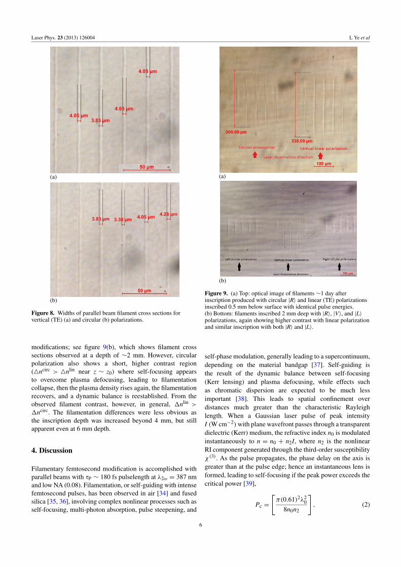
To investigate the effects of polarization inscriptionduring filamentation, the filament widths and lengths wereinvestigated after exposure. Figure 8 shows optical images ofparallel filaments written with vertical linear (TE) and circularpolarizations. The filament widths, measured over sets often, were found to be essentially independent of the writingpolarization and the average width over many filaments andall polarizations, 〈W〉 = 4.02± 0.02 µm (1σ).
Sets of filaments were inscribed using single-beaminscription with linear (TE) and circular polarizations witha pulse energy EP = 0.301 ± 0.0013 µJ (1σ). Thedetector response (J3-05, Molectron) was checked carefullyand determined to be independent of polarization withinexperimental error. For these experiments, the quarter-waveplate fast axis orientation was rotated from vertical, parallelto the incident linear polarization |V〉, to ±45◦ to generate|R〉 and |L〉 circular polarizations. Figures 9(a) and (b)show the optical images (in transmission) of the filamentarymodification cross sections observed between filamentsinscribed with linear (TE) and circular polarizations. Thereis clearly a significant difference in filamentary modifications.With linear polarization, the inscribed filaments appear moreuniform, and appear to have higher RI contrast than withcircular polarization (4nlin > 4ncirc), while also originatingnearer the laser source by around 4L ∼ 40 µm. As expectedfrom symmetry, right and left polarizations generate similar
5
Laser Phys. 23 (2013) 126004 L Ye et al
(a)
(b)
Figure 8. Widths of parallel beam filament cross sections forvertical (TE) (a) and circular (b) polarizations.
modifications; see figure 9(b), which shows filament crosssections observed at a depth of ∼2 mm. However, circularpolarization also shows a short, higher contrast region(4ncirc > 4nlin near z ∼ z0) where self-focusing appearsto overcome plasma defocusing, leading to filamentationcollapse, then the plasma density rises again, the filamentationrecovers, and a dynamic balance is reestablished. From theobserved filament contrast, however, in general, 1nlin >
1ncirc. The filamentation differences were less obvious asthe inscription depth was increased beyond 4 mm, but stillapparent even at 6 mm depth.
4. Discussion
Filamentary femtosecond modification is accomplished withparallel beams with τP ∼ 180 fs pulselength at λ2ω = 387 nmand low NA (0.08). Filamentation, or self-guiding with intensefemtosecond pulses, has been observed in air [34] and fusedsilica [35, 36], involving complex nonlinear processes such asself-focusing, multi-photon absorption, pulse steepening, and
(a)
(b)
Figure 9. (a) Top: optical image of filaments ∼1 day afterinscription produced with circular |R〉 and linear (TE) polarizationsinscribed 0.5 mm below surface with identical pulse energies.(b) Bottom: filaments inscribed 2 mm deep with |R〉, |V〉, and |L〉polarizations, again showing higher contrast with linear polarizationand similar inscription with both |R〉 and |L〉.
self-phase modulation, generally leading to a supercontinuum,depending on the material bandgap [37]. Self-guiding isthe result of the dynamic balance between self-focusing(Kerr lensing) and plasma defocusing, while effects suchas chromatic dispersion are expected to be much lessimportant [38]. This leads to spatial confinement overdistances much greater than the characteristic Rayleighlength. When a Gaussian laser pulse of peak intensityI (W cm−2)with plane wavefront passes through a transparentdielectric (Kerr) medium, the refractive index n0 is modulatedinstantaneously to n = n0 + n2I, where n2 is the nonlinearRI component generated through the third-order susceptibilityχ (3). As the pulse propagates, the phase delay on the axis isgreater than at the pulse edge; hence an instantaneous lens isformed, leading to self-focusing if the peak power exceeds thecritical power [39],
Pc =
[π(0.61)2λ2
0
8n0n2
], (2)
6

Laser Phys. 23 (2013) 126004 L Ye et al
overcoming diffraction. Theoretically, self-focusing wouldlead to a singularity, but it is prevented from doing so byplasma defocusing. As the intensity increases, nonlinear MPIgenerates seed electrons in the conduction band, followed byimpact ionization; hence a free electron plasma with densityρe(t) grows exponentially (highest density ρe on axis). Thiscreates a negative lens which balances the self-focusing,leading to confinement of the radiation in a filament, wherethe ultrahigh intensity (here, I ∼ 1.2 × 10¹³ W cm−2)is clamped [35]. The filament lengths observed here areδL ∼ 338 µm (figure 9(a)) while the Rayleigh length RL =
(πn0ω2
0λ0) = 48.4 µm (ω0 = 2 µm, λ0 = 0.387 µm); hence
δL� RL, as expected. During the study of transient plasmasin fs waveguiding in doped phosphate glass with temporalpulselengths 100 < τp < 400 fs, Gawelda et al [40] observedclear polarization-dependent effects in filamentation whichdiminished with increasing temporal pulselength and fullysuppressed at 400 fs with circular polarization while still beingpresent with linear polarization. The results were consistentwith a difference in critical powers: Plin
C = 1.03 MW andPcirc
C = 1.53 MW, a factor of ∼1.5 higher. The ratio ofthe nonlinear refractive indices nlin
2 and ncirc2 in an isotropic
dielectric medium scale as ncirc2 /nlin
2 = 1.5 [39] due to the factthat the third-order susceptibility χ (3) (which is a tensor) hasonly one component with circular polarization whereas thelinear polarization has two components. The ratio of criticalpowers is expected to be Pcirc
C /PlinC = 1.5; thus self-focusing
is weaker with circular than linear polarization and consistentwith observations during filamentation in a pure polymer,PMMA.
PMMA has a band gap of Eb = 4.58 eV [25], so that MPIis initiated by 2-photon absorption at 387 nm (hν = 3.2 eV),and since the temporal pulselength is τp ∼ 180 fs impactionization is also significant. The electron density may reachρe > 1019 cm−3, where irreversible modification occurs. Thepeak intensity I in each filament can be estimated to beI = ( 2EP
πω20τP) ∼ 1.22 × 10¹³ W cm−2 with 1/e2 focal spot
size 2ω0 ∼1.22λNA = 5.9 µm, while the peak power of each
diffracted beam is P = 1.7 MW (0.31 µJ180 fs ).
The observed filamentation differences (figures 9(a), (b))with linear and circular polarizations indicate that the ratio ofcritical powers Plin
C /PcircC > 1 in PMMA and that filamentation
leads to stronger coupling and higher 〈1n〉 with linearpolarization. The relationship between n2 and the third-ordersusceptibility χ (3) is given by [41]
n2 =0.0395χ (3)
n20
, (3)
where n2 has units cm2 W−1 and χ (3) is measured inesu. In optical solids, the value of χ (3) is typically in therange 10−13–10−14 esu [40]. For example, the value ofχ (3) in PMMA at λ = 1500 nm was estimated to be [42]χ (3) ∼ 3 × 10⁻¹⁴ esu and, as χ (3) scales linearly withwavelength, then χ (3)387/χ
(3)1500 = 0.258, yielding χ (3)387 ∼ 7.7 ×
10−15; hence n3872 ∼ 1.37 × 10⁻¹⁶ cm2 W−1. The critical
power for self-focusing in PMMA (equation (2)) is therefore
PC ∼ 1.1 MW, while the peak power in each beam P =1.7 MW ∼ 1.5PC, which confirms that self-focusing willoccur ahead of the geometrical focus inside the material. Thevalue of χ (3) quoted by D’Amore et al [42] was measuredon a thin film of PMMA by third-harmonic generation andwith accuracy limited by significant background from thefused silica substrate. This places an uncertainty on the criticalpower calculated at 387 nm above; hence we have alsoestimated n387
2 as follows, with a very simple model [39].From the observed filament widths, self-guiding was
limited to a diameter ϕ = 4.0 µm during filamentation. Thiscan be compared to a waveguide whose core has RI = n0+δn,while outside RI = n0. The critical angle for traversing rays ina waveguide is given by θc = (2δn/n0)
1/2, while the angle ofdiffraction of a Gaussian beam of diameter ϕ is given by θdif =
0.61λ/n0ϕ, so guiding will occur if all rays experience totalinternal reflection, that is when θc = (2δn/n0)
1/2= θdif =
0.61λ/n0ϕ; hence
δn387 = n3872 I = n0
(0.61λ0)2
2(n0ϕ)2. (4)
With I = 1.22 × 10¹³ W cm−2, λ0 = 3.87 × 10⁻⁵ cm,ϕ = 4.0 × 10⁻⁴ cm, and n0 = 1.49, we obtain a valuen387
2 = 9.58 × 10⁻¹⁷ cm2 W−1, in reasonable agreementwith the value in D’Amore [42] (1.37 × 10⁻¹⁶ cm2 W−1)and lower by a factor of 0.7. The proximity of these valuessupports the linear scaling of χ (3) to shorter wavelengths.The RI modulation during self-guiding in PMMA is δn =n387
2 I ∼ 1.67×10⁻³, a level consistent with a strongly guidingstructure. Interestingly, a collimated beam at 387 nm (2ω0 =
0.8 cm) with peak power P ∼ 1.7 PC traversing a 10 cm thickPMMA sample should self-focus in a distance [39] Zsf =
ω(n0/2n2I)0.5 ∼ 8.4 cm, and then avoid collapse throughfilamentation.
The plasma electron density, %e, which balances theself-focusing attained in the filaments, can be estimated fromthe real part Re(1n) of the Drude equation for the RI changedue to the plasma [36],
1n = n3872 I =
[e2
2n0ε0ω2me
] [ρeω
2τ 2c
1+ ω2τ 2c
], (5)
where e and me are the electron’s charge and mass, ε0 is thepermittivity of free space, n0 (1.49) is the linear refractiveindex, ρe is the electron density, ω(387 nm) is the laserfrequency (3.87×10¹⁵ rad s−1), and τc is the electron collisiontime. If τc is of the order of 1 fs or greater (τc = 0.4 fs in fusedsilica), the ratio ω2τ 2
c /(1+ω2τ 2
c ) > 0.96 and it tends closer tounity as τc increases. Hence we obtain, as n2I = 1.67× 10⁻³,an estimate of the electron density in a filament, with the helpof equation (5):
ρe =2n0ε0ω
2me(n2I)
e2
= 2.22× 10²²· (n2I) = 4.3× 1019 cm−3. (6)
This value is of the correct order required to producepermanent modification [37] and well below the criticalplasma density ρcrit
e ∼ 1021 cm−3 which would result in
7
Laser Phys. 23 (2013) 126004 L Ye et al
complete optical breakdown. As the scan speed s = 1 mm s−1
during inscription, corresponding to s = 1 µm ms−1, thematerial is exposed to only ∼4 overlapped pulses duringinscription of 4 µm wide structures.
As nlin2 > ncirc
2 , equation (6) infers that the plasma densityreached with linear polarization should be higher than thatwith circular polarization. Diffraction efficiencies measuredsoon after inscription should therefore reflect the degree ofbond breaking in the polymer, dependent on the plasmaformation during filamentation.
The grating efficiencies depend on the phase angle φ,where φ(|P〉) = π1nPL/λ cos θB for a grating of length L and|P〉 is the state of polarization. As the inscribed filament crosssections for linear and circular polarizations are different,then allowing for slight variation in 1nP with depth z, thedifference in first-order DEs is related to the changes in opticalpath length OPD = δ(1nPL), given by
δ(OPD) =∫[1nlin(z)−1ncirc(z)] dz
= [〈1nlin〉 − 〈1ncirc
〉]L. (7)
The observed DE after 1 day for linear (TE) polarizationwas 62% (figure 5), while the ratio of diffraction efficienciesR= (sin2
〈α1nlin〉/sin2
〈α1ncirc〉)= 1.21±0.03 after∼1 day,
which leads to (〈1nlin〉/〈1ncirc
〉)max ∼ 1.13 ± 0.03 whenaveraged throughout a 4 mm grating structure, a modestthough significant variation.
As 2-photon absorption (also related to third-ordersusceptibility χ (3)) initiates the nonlinear ionization processin PMMA at 387 nm, there may be a polarization-dependenteffect on the 2-photon absorption cross section ratios inPMMA which initiates plasma formation.
Effects of polarization in multi-photon ionization (MPI)were first observed in 1971 during the 3-photon ionizationof atomic caesium with a ruby laser where experimentally,
the ratio of cross sections was found to be (σ circ
3σ lin
3) = 2.15 ±
0.4 [43]. Following this, experiments on 2-photon ionization
of caesium yielded the ratio (σ circ
2σ lin
2) = 1.28 ± 0.2 [44].
These experiments inspired theoretical work on MPI [45, 46]which predicted the dominance of circular polarization in
low-order MPI, N ≤ 3 with upper limits (σ circ
2σ lin
2) = 3/2
and (σ circ
3σ lin
3) = 5/2, so the theory and experiments were in
reasonable agreement. The general arguments related toangular momentum conservation during MPI were expectedto apply also in solids, confirmed with 4-photon conductivity
experiments in quartz, yielding (σ circ
2σ lin
2) = 2.05 ± 0.9 [47].
Reiss [46] pointed out, however, that a significant reversalof this behaviour was expected for N > 4 and confirmed inhigh N, 6-photon resonance-enhanced MPI (REMPI, 3 + 3),
in the NO molecule, yielding (σ lin
6σ circ
6) ∼ 2.9 [48]. In addition,
single-pulse, (50 fs, 800 nm) 6-photon ionization in fusedsilica at peak intensities I ∼ 10–20 TW cm−2 yielded the
ratio of absorption cross sections (σ lin
6σ circ
6) ∼ 3.7 [49]. However,
the RI contrast during waveguide inscription in fused silica(120 fs, 1 kHz, 800 nm, 0.46NA) was both polarization andintensity dependent [50].
The plasma densities reached in filaments (equation (6))with linear and circular polarization could be expected tovary by a factor of 3/2, leading to (〈1nlin
〉/〈1ncirc〉)theory ∼
1.5, assuming that 1n n ρe. However, the ratio isclearly much lower, (〈1nlin
〉/〈1ncirc〉) ∼ 1.13. However,
if the ratio of two-photon ionization cross sections inPMMA was similar that observed in atomic caesium,
that is, favouring circular polarization, with (σ circ
2σ lin
2) ∼
1.28 [44], then circular polarization could enhance 2-photonionization over linear polarization, increasing the initialseed electron density available for impact ionization. Thiseffect could reduce the differential in final plasma densities,yielding (〈1nlin
〉/〈1ncirc〉) ∼ 1.5
1.28 = 1.17, closer to the ratio(〈1nlin
〉/〈1ncirc〉)max ∼ 1.13 ± 0.03 estimated from the
measured first-order diffraction efficiencies. This may be afortuitous result and would require additional confirmationby high NA, polarization-dependent experiments (defeatingfilamentation) of 2-photon absorption coefficients, wellbeyond the scope of the current paper.
The photochemical changes in pure PMMA after fsinscription with NUV pulses at 387 nm have previously beenanalysed in detail [25] and, more recently, Raman mappingafter fs exposure at 400 nm confirmed the increased density(relative to surrounding material) of C=C bonds, detectedat wavenumber $ = 1640 cm−1 [51]. These bonds arefound only in the monomer and end groups of PMMA,supporting the view that fs exposure in PMMA causes chainscission of the polymer backbone and depolymerization [25].The temporal development over 30 days might well bedue to diffusion of monomer MMA into unexposed regionscombined with cross linking and stress relaxation. As linearpolarization appears to couple strongest to the substrate, weinfer that it creates more chain scission (bond breaking)in filaments than with circular polarization [52]. The 1nsobserved after exposure, and differences due to polarization,although modest, support this view.
5. Conclusions
We have used low NA, parallel beam NUV fs inscriptionwith a phase-only SLM to create high efficiency VBGsin pure PMMA with thickness L = 1–7 mm, reaching thefirst-order Bragg efficiency η1 ∼ 94% with L = 4 mm, wheninscribed with linear vertical polarization (TE) perpendicularto the scan direction. The diffraction efficiency is the highestachieved in a pure polymer as far as the authors areaware. An excellent fit to Kogelnik theory η±1 = sin2ϕ
was observed [31] and used to estimate the RI modulation,which reached 1nlin
TE = (6.01 ± 0.07) × 10−5 after 30 days.The excellent fit to the theoretical curve infers that VBGsare approaching device level quality. By inscribing setsof 5 mm thick VBGs with the same pulse energy butdifferent linear and circular polarizations |V〉, |H〉, |R〉, |L〉,
8

Laser Phys. 23 (2013) 126004 L Ye et al
maximum diffraction efficiency was observed with linearvertical polarization |V〉(TE), then horizontal |H〉(TM) (TM),and lowest with circular polarization. The ratio of first-orderDEs was [η1(|V〉)/η1(|R〉)]max = 1.21 ± 0.03 soon afterinscription. By studying the filamentary inscription crosssections made under identical energies but with linear(TE) and circular polarizations, a polarization-dependentfilamentary modification was confirmed, stronger with linearthan circular polarization. This is consistent with the observedstronger self-focusing with linear than circular polarization,and was theoretically predicted [39]. The observed ratio ofdiffraction efficiencies infers that (〈1nlin
〉/〈1ncirc〉)max =
1.13± 0.03 when averaged over a 5 mm thick structure.While linear polarization gave highest 1n, inscribed
VBGs displayed higher background (6–8%) than with circularpolarization, 2–3%. The source of the background is underinvestigation. There may, for example, be a remainingsmall stitching error or possibly an effect due to imperfectuniformity between the parallel spots. In the case oflinear (TE) polarization, periodic nanostructures can bewritten within the filaments during exposure, increasingcoupling to the plasma due to the interference of the laserelectric field with bulk electron plasma waves [53]. Surfaceablation of PMMA with 45 fs, 800 nm pulses showsa strong asymmetry due to polarization dependence [54].The inscription symmetry offered by circular polarization isclearly desirable to avoid such effects.
Acknowledgments
We are grateful to Professor Miles Padgett of GlasgowUniversity for the use of the Labview software for calculatingphase CGHs.
References
[1] Arns J A, Colburn W C and Barden S C 1999 Proc. SPIE3779 313–23
[2] Volodin B L, Dolgy S V, Melnik E D, Shaw J and Ban V S2004 Opt. Lett. 29 1891–3
[3] Glebov A L, Mokhun O, Rapaport A, Vergnole S, Smirnov Vand Glebov L B 2012 Proc. SPIE 8428 84280C
[4] Liao K H et al 2007 Opt. Express 15 4876–82[5] Shankoff T A 1968 Appl. Opt. 7 2101–5[6] Efimov O M, Glebov L B, Glebova L N, Ricahrdson K C and
Smirnov V I 1999 Appl. Opt. 38 619–27[7] Ciapurin I G, Glebov L B, Glebova L N, Smirnov V L and
Rotari E V 2003 Proc. SPIE 4974 209–19[8] Davis K M, Miura K, Sugimoto N and Hirao K 1996 Opt. Lett.
21 1729–31[9] Ossellame R, Cerulloa G and Ramponi R (ed) 2011 Fs Laser
Micro-Machining (Topics in Applied Physics vol 123)(Heidelberg: Springer) pp 155–95
[10] Watanabe W and Itoh K 2004 Proc. SPIE 5340 119–26[11] Paipulas D, Kudriasov V, Kurselis K, Malinauskas M, Ost S
and Sirutkaitis V 2010 LPM 2010: Proc. 11th Int. Symp. onLaser Precision Microfabrication (Stuttgart, June 2010)
[12] Voiglander C, Richter D, Thomas J, Tunnermann A andNolte S 2010 Appl. Phys. A 102 35–8
[13] Lee D, Thomson R R and Cunningham C R 2012Instrumentation and methods for astrophysicsarXiv:1207.2661 [astro-phIM]
[14] Yamasaki K, Juodkazis S, Lippert T, Watanabe M, Matsuo Sand Misawa H 2003 Appl. Phys. A 76 325–9
[15] Mizeikes V, Seet K K, Juodkasis S and Misawa H 2004 Proc.SPIE 5662 95–100
[16] Zoubir A, Lopez C, Richardson M and Richardson K 2004Opt. Lett. 29 1840–2
[17] Watanabe W, Sowa S, Tamaki T, Itoh K and Nishii J 2006Japan. J. Appl. Phys. 45 L765–7
[18] Yamasaki K, Juodkazis S, Matsuo S and Misawa H 2003 Appl.Phys. A 77 371–3
[19] Uppal N, Shiakolas P S and Rizwan M 2008 Proc. SPIE6882 68820I
[20] Si J, Qiu J, Zhai J, Shen Y and Hirao K 2002 Appl. Phys. Lett.80 359–61
[21] Scully P J, Jones D and Jaroszynski D A 2003 J. Opt. A: PureAppl. Opt. 5 S92–6
[22] Mochizuki H, Watanabe W, Ezoe R, Tamaki T, Ozeki Y,Itoh K, Kasuya M, Matsuda K and Hirono S 2008 Appl.Phys. Lett. 92 091120
[23] Baum A, Scully P J, Perrie W, Jones D, Isaac R andJaroszynski D A 2008 Opt. Lett. 33 651–3
[24] Watanabe W 2009 Laser Phys. 19 342–5[25] Baum A, Scully P J, Basanta M, Paul Thomas C L,
Fielden P R, Goddard N J, Perrie W and Chalker P 2007Opt. Lett. 32 190–2
[26] Hasegawa S and Hayasaki Y 2007 Proc. SPIE 6458 1–15[27] Liu D, Kuang Z, Perrie W, Scully P J, Baum A,
Edwardson S P, Fearon E, Dearden G and Watkins K G2010 Appl. Phys. B 101 817–23
[28] Liu D, Perrie W, Kuang Z, Scully P J, Baum A, Liang S,Edwardson S P, Fearon E, Dearden G and Watkins K G2012 Appl. Phys. B 107 795–801
[29] Leach J, Sinclair G, Jordan P, Courtial J, Padgett M J andLaczik Z 2004 Opt. Express 12 220
[30] Kazansky P G, Yang W, Briochi E, Bovatsek J, Arai A,Shimotsuma Y, Miura K and Hirao K 2007 Appl. Phys.Lett. 90 151120
[31] Kogelnik H 1969 Bell Syst. Tech. J. 48 2909[32] Hnatovski C, Taylor R S, Simova E, Bhardwai V R,
Raynor D M and Corkum P B 2005 J. Appl. Phys.98 013517
[33] Ciapurin I V, Glebov L B and Smirnov V I 2005 Proc. SPIE5742 183
[34] Braun A, Korn G, Liu X, Du D, Squier J and Mourou G 1995Opt. Lett. 20 73
[35] Tzortzakis S, Sudrie L, Franco M, Prade B, Mysyrowicz A,Couairon A and Berge L 2001 Phys. Rev. Lett. 87 213902
[36] Tzortzakis S, Papazoglou D G and Zergioti I 2006 Opt. Lett.31 796–8
[37] Brodeur A and Chin S L 1998 Phys. Rev. Lett. 80 4406–9[38] Couairon A, Gaizauskas E, Faccio D, Dubietis A and
Di Trapani P 2006 Phys. Rev. E 73 016608[39] Boyd R W 2008 Nonlinear Optics 3rd edn (Burlington, MA:
Academic) chapter 4, pp 207–52[40] Gawelda W, Puerto D, Seigal J, Ferrer A, Ruiz de la Cruz A,
Fernadez H and Solis J 2008 Appl. Phys. Lett. 93 121109[41] Boyd R W and Fischer G L 2001 Nonlinear optical materials
Encyclopedia of Materials; Science and Technology(Oxford: Elsevier) pp 6237–44
[42] D’Amore F, Lanata M, Pietralunga S M, Gallazzi M C andZerbi G 2004 Opt. Mater. 24 661–5
[43] Fox R A, Kogan R M and Robinson E J 1971 Phys. Rev. Lett.26 1416
9

Laser Phys. 23 (2013) 126004 L Ye et al
[44] Kogan R M, Fox R A, Burnham G T and Robinson E J 1971Bull. Am. Phys. Soc. 16 1411
[45] Klarsfeld S and Maquet A 1972 Phys. Rev. Lett. 29 79–81[46] Reiss H R 1972 Phys. Rev. Lett. 29 1129–31[47] Venable D D and Kay R B 1975 Appl. Phys. Lett. 27 48[48] Carman H S and Compton R N 1989 J. Chem. Phys. 90 1307[49] Temnov V V, Sokolowsli-Tinten K, Zhou P, El-Khamhawy A
and von der Linde D 2006 Phys. Rev. Lett. 97 237403[50] Little D J, Ams M, Dekker P, Marshall G D, Dawes J M and
Withford M J 2008 Opt. Express 16 20029
[51] Pang B, Taranu A, Liang S, Casabella S, Fiadzomor P andScully P 2011 POF 2011: Proc. 20th Int. Conf. PlasticOptical Fibers (Bilbao, Sept. 2011)
[52] Baum A, Scully P J, Perrie W, Liu D and Lucarini V 2010J. Opt. Soc. Am. B 27 107–11
[53] Shimotsuma Y, Kazansky P G, Qiu J and Hirao K 2003 Phys.Rev. Lett. 91 247405
[54] Guay J M, Villafranca A, Baset F, Popov K, Ramunno L andBhardwaj V R 2012 New J. Phys. 14 085010
10