Embed Size (px)
Citation preview
Nuvation Energy High-Voltage BMS
NUV100 Datasheet
2019-08-27
Table of Contents
1. System Overview . . . . . . . . . . . . . . . . . . . . . . . . . . . . . . . . . . . . . . . . . . . . . . . . . . . . . . . . 1
2. High-Voltage Stack Controller . . . . . . . . . . . . . . . . . . . . . . . . . . . . . . . . . . . . . . . . . . . . . . . . 2
2.1. Hardware Overview . . . . . . . . . . . . . . . . . . . . . . . . . . . . . . . . . . . . . . . . . . . . . . . . . . . . 2
2.1.1. Ethernet. . . . . . . . . . . . . . . . . . . . . . . . . . . . . . . . . . . . . . . . . . . . . . . . . . . . . . . . . 2
2.1.2. CAN 485. . . . . . . . . . . . . . . . . . . . . . . . . . . . . . . . . . . . . . . . . . . . . . . . . . . . . . . . . 2
2.1.3. GPIO-Out . . . . . . . . . . . . . . . . . . . . . . . . . . . . . . . . . . . . . . . . . . . . . . . . . . . . . . . . 2
2.1.4. GPIO-In . . . . . . . . . . . . . . . . . . . . . . . . . . . . . . . . . . . . . . . . . . . . . . . . . . . . . . . . . 3
2.1.5. Link Out . . . . . . . . . . . . . . . . . . . . . . . . . . . . . . . . . . . . . . . . . . . . . . . . . . . . . . . . . 3
2.1.6. Stack Bus. . . . . . . . . . . . . . . . . . . . . . . . . . . . . . . . . . . . . . . . . . . . . . . . . . . . . . . . 3
2.1.7. Indicator LEDs . . . . . . . . . . . . . . . . . . . . . . . . . . . . . . . . . . . . . . . . . . . . . . . . . . . . 3
2.2. Operating Limits . . . . . . . . . . . . . . . . . . . . . . . . . . . . . . . . . . . . . . . . . . . . . . . . . . . . . . 4
2.3. Mechanical Overview . . . . . . . . . . . . . . . . . . . . . . . . . . . . . . . . . . . . . . . . . . . . . . . . . . . 7
3. High-Voltage Power Interface . . . . . . . . . . . . . . . . . . . . . . . . . . . . . . . . . . . . . . . . . . . . . . . . 8
3.1. Hardware Overview . . . . . . . . . . . . . . . . . . . . . . . . . . . . . . . . . . . . . . . . . . . . . . . . . . . . 8
3.1.1. Contactors . . . . . . . . . . . . . . . . . . . . . . . . . . . . . . . . . . . . . . . . . . . . . . . . . . . . . . . 8
3.1.2. Interlock . . . . . . . . . . . . . . . . . . . . . . . . . . . . . . . . . . . . . . . . . . . . . . . . . . . . . . . . 8
3.1.3. External Power . . . . . . . . . . . . . . . . . . . . . . . . . . . . . . . . . . . . . . . . . . . . . . . . . . . . 9
3.1.4. Stack Power . . . . . . . . . . . . . . . . . . . . . . . . . . . . . . . . . . . . . . . . . . . . . . . . . . . . . . 9
3.1.5. Current Shunt. . . . . . . . . . . . . . . . . . . . . . . . . . . . . . . . . . . . . . . . . . . . . . . . . . . . . 9
3.1.6. Thermistor . . . . . . . . . . . . . . . . . . . . . . . . . . . . . . . . . . . . . . . . . . . . . . . . . . . . . . . 9
3.1.7. Stack Bus. . . . . . . . . . . . . . . . . . . . . . . . . . . . . . . . . . . . . . . . . . . . . . . . . . . . . . . . 9
3.1.8. Indicator LEDs . . . . . . . . . . . . . . . . . . . . . . . . . . . . . . . . . . . . . . . . . . . . . . . . . . . . 9
3.1.9. Reset Push-Button . . . . . . . . . . . . . . . . . . . . . . . . . . . . . . . . . . . . . . . . . . . . . . . . . 10
3.2. Operating Limits . . . . . . . . . . . . . . . . . . . . . . . . . . . . . . . . . . . . . . . . . . . . . . . . . . . . . 11
3.3. Mechanical Overview . . . . . . . . . . . . . . . . . . . . . . . . . . . . . . . . . . . . . . . . . . . . . . . . . . 13
4. Nuvation Energy Cell Interface . . . . . . . . . . . . . . . . . . . . . . . . . . . . . . . . . . . . . . . . . . . . . . 14
5. Ordering Information . . . . . . . . . . . . . . . . . . . . . . . . . . . . . . . . . . . . . . . . . . . . . . . . . . . . . 15
1. System Overview
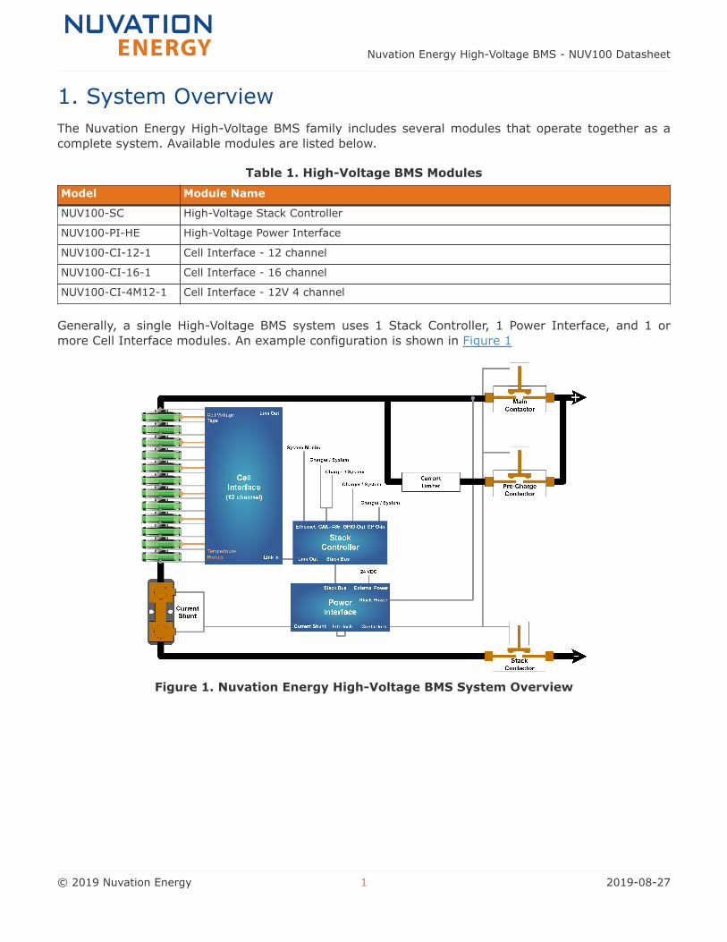
The Nuvation Energy High-Voltage BMS family includes several modules that operate together as a
complete system. Available modules are listed below.
Table 1. High-Voltage BMS Modules
Model Module Name
NUV100-SC High-Voltage Stack Controller
NUV100-PI-HE High-Voltage Power Interface
NUV100-CI-12-1 Cell Interface - 12 channel
NUV100-CI-16-1 Cell Interface - 16 channel
NUV100-CI-4M12-1 Cell Interface - 12V 4 channel
Generally, a single High-Voltage BMS system uses 1 Stack Controller, 1 Power Interface, and 1 or
more Cell Interface modules. An example configuration is shown in Figure 1
Figure 1. Nuvation Energy High-Voltage BMS System Overview
Nuvation Energy High-Voltage BMS - NUV100 Datasheet
© 2019 Nuvation Energy 1 2019-08-27
2. High-Voltage Stack Controller
2.1. Hardware Overview
High-Voltage Stack Controller module contains the central MCU which handles all the processes and
decision making required by Nuvation Energy High-Voltage BMS. The external interfaces to this
module are:
• 10/100 Base-T Ethernet RJ45 jack
• Isolated CAN 2.0 port
• RS-485 (Modbus) connector
• 4 opto-isolated digital outputs
• 4 opto-isolated digital inputs
• Link Bus connector
• Stack Bus connector
• 3 Indicator LEDs
Stack Controller does not have high-voltage connectors and does not connect to any battery stack-
referenced signals, making it safe to handle and connect to external equipment.
The following subsections describe the external interfaces in more detail. For wiring/pin-out
information, please refer to the Nuvation Energy High-Voltage BMS: Installation Guide, available
online at https://www.nuvationenergy.com/technical-resources
2.1.1. Ethernet
The Ethernet jack is a standard RJ45 Cat5e rated jack. This interface is used as the primary means of
connecting an external system to the BMS to configure the operating parameters and observe the
status. It is also used as a means of controlling an external battery charger/inverter and
communicating with the external system (vehicle central controller, grid-attached site controller, etc.)
The two LEDs on the Ethernet jack indicate link status (green LED) and network activity (yellow LED).
2.1.2. CAN 485
The CAN 485 connector is a 12-pin Micro-Fit 3.0™ Molex connector. This interface provides an isolated
CAN 2.0 port as well as a non-isolated RS-485 (Modbus) port. This interface can be used to control an
external battery charger/inverter and communicating with the external system (vehicle central
controller, grid-attached controller, etc.)
2.1.3. GPIO-Out
The GPIO-Out connector is a 10-pin Micro-Fit 3.0™ Molex connector. This interface provides 4 isolated
outputs (output of a solid-state relay) to allow an external system to receive digital input from the
Stack Controller. The functionality of this interface is configured by the end-user to match their needs.
Nuvation Energy High-Voltage BMS - NUV100 Datasheet
© 2019 Nuvation Energy 2 2019-08-27
2.1.4. GPIO-In
The GPIO-In connector is an 8-pin Micro-Fit 3.0™ Molex connector. This interface provides 4 isolated
inputs (cathode of an optocoupler) to allow an external system to send digital output to the Stack
Controller. The functionality of this interface is configured by the end user to match their needs.
2.1.5. Link Out
The Link Out connector is a 4-pin Micro-Fit 3.0™ Molex connector. This interface is used to connect
the Stack Controller to the string of one or more Cell Interface modules. The Link In connector on the
Cell Interface monitoring the lowest-potential cell in the series battery stack is connected to this
connector via a Link Bus cable. The Link Out connector also provides operating power to the Cell
Interface modules.
2.1.6. Stack Bus
The Stack Bus connector is a 6-pin Mini-Fit® Jr. Molex connector. This interface is used to connect the
Power Interface to the Stack Controller. The Stack Controller is powered from the Stack Bus.
2.1.7. Indicator LEDs
The 3 LEDs are used by the Stack Controller to indicate health and functional status to the user. All
LEDs are controlled by the central MCU. The 'Power' LED indicates the MCU is operational, the
'Activity' LED indicates the MCU is processing data and the 'Fault' LED indicates that Nuvation Energy
BMS has detected a Fault.
Nuvation Energy High-Voltage BMS - NUV100 Datasheet
© 2019 Nuvation Energy 3 2019-08-27
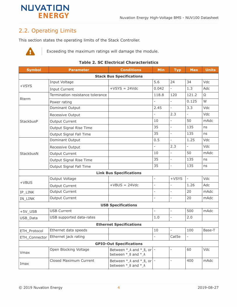
2.2. Operating Limits
This section states the operating limits of the Stack Controller.
Exceeding the maximum ratings will damage the module.
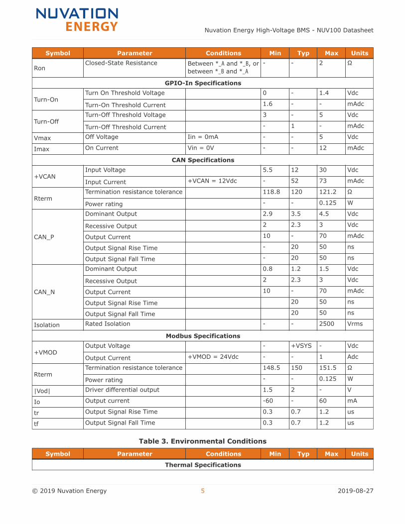
Table 2. SC Electrical Characteristics
Symbol Parameter Conditions Min Typ Max Units
Stack Bus Specifications
+VSYSInput Voltage 5.6 24 34 Vdc
Input Current +VSYS = 24Vdc 0.042 - 1.3 Adc
RtermTermination resistance tolerance 118.8 120 121.2 Ω
Power rating - - 0.125 W
StackbusP
Dominant Output 2.45 - 3.3 Vdc
Recessive Output - 2.3 - Vdc
Output Current 10 - 50 mAdc
Output Signal Rise Time 35 - 135 ns
Output Signal Fall Time 35 - 135 ns
StackbusN
Dominant Output 0.5 - 1.25 Vdc
Recessive Output - 2.3 - Vdc
Output Current 10 - 50 mAdc
Output Signal Rise Time 35 - 135 ns
Output Signal Fall Time 35 - 135 ns
Link Bus Specifications
+VBUSOutput Voltage - +VSYS - Vdc
Output Current +VBUS = 24Vdc - - 1.26 Adc
IP_LINK Output Current - - 20 mAdc
IN_LINK Output Current - - 20 mAdc
USB Specifications
+5V_USB USB Current - - 500 mAdc
USB_Data USB supported data-rates 1.0 - 2.0
Ethernet Specifications
ETH_Protocol Ethernet data speeds 10 - 100 Base-T
ETH_Connector Ethernet jack rating - Cat5e -
GPIO-Out Specifications
VmaxOpen Blocking Voltage Between *_A and *_B, or
between *_B and *_A
- - 60 Vdc
ImaxClosed Maximum Current Between *_A and *_B, or
between *_B and *_A
- - 400 mAdc
Nuvation Energy High-Voltage BMS - NUV100 Datasheet
© 2019 Nuvation Energy 4 2019-08-27
Symbol Parameter Conditions Min Typ Max Units
RonClosed-State Resistance Between *_A and *_B, or
between *_B and *_A
- - 2 Ω
GPIO-In Specifications
Turn-OnTurn On Threshold Voltage 0 - 1.4 Vdc
Turn-On Threshold Current 1.6 - - mAdc
Turn-OffTurn-Off Threshold Voltage 3 - 5 Vdc
Turn-Off Threshold Current - 1 - mAdc
Vmax Off Voltage Iin = 0mA - - 5 Vdc
Imax On Current Vin = 0V - - 12 mAdc
CAN Specifications
+VCANInput Voltage 5.5 12 30 Vdc
Input Current +VCAN = 12Vdc - 52 73 mAdc
RtermTermination resistance tolerance 118.8 120 121.2 Ω
Power rating - - 0.125 W
CAN_P
Dominant Output 2.9 3.5 4.5 Vdc
Recessive Output 2 2.3 3 Vdc
Output Current 10 - 70 mAdc
Output Signal Rise Time - 20 50 ns
Output Signal Fall Time - 20 50 ns
CAN_N
Dominant Output 0.8 1.2 1.5 Vdc
Recessive Output 2 2.3 3 Vdc
Output Current 10 - 70 mAdc
Output Signal Rise Time 20 50 ns
Output Signal Fall Time 20 50 ns
Isolation Rated Isolation - - 2500 Vrms
Modbus Specifications
+VMODOutput Voltage - +VSYS - Vdc
Output Current +VMOD = 24Vdc - - 1 Adc
RtermTermination resistance tolerance 148.5 150 151.5 Ω
Power rating - - 0.125 W
|Vod| Driver differential output 1.5 2 - V
Io Output current -60 - 60 mA
tr Output Signal Rise Time 0.3 0.7 1.2 us
tf Output Signal Fall Time 0.3 0.7 1.2 us
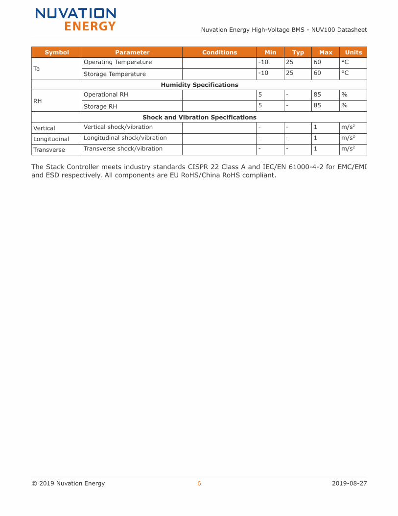
Table 3. Environmental Conditions
Symbol Parameter Conditions Min Typ Max Units
Thermal Specifications
Nuvation Energy High-Voltage BMS - NUV100 Datasheet
© 2019 Nuvation Energy 5 2019-08-27
Symbol Parameter Conditions Min Typ Max Units
TaOperating Temperature -10 25 60 °C
Storage Temperature -10 25 60 °C
Humidity Specifications
RHOperational RH 5 - 85 %
Storage RH 5 - 85 %
Shock and Vibration Specifications
Vertical Vertical shock/vibration - - 1 m/s2
Longitudinal Longitudinal shock/vibration - - 1 m/s2
Transverse Transverse shock/vibration - - 1 m/s2
The Stack Controller meets industry standards CISPR 22 Class A and IEC/EN 61000-4-2 for EMC/EMI
and ESD respectively. All components are EU RoHS/China RoHS compliant.
Nuvation Energy High-Voltage BMS - NUV100 Datasheet
© 2019 Nuvation Energy 6 2019-08-27
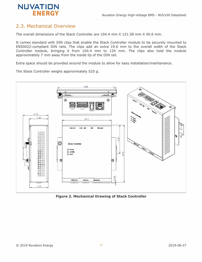
2.3. Mechanical Overview
The overall dimensions of the Stack Controller are 104.4 mm X 121.58 mm X 40.6 mm.
It comes standard with DIN clips that enable the Stack Controller module to be securely mounted to
EN50022-compliant DIN rails. The clips add an extra 19.6 mm to the overall width of the Stack
Controller module, bringing it from 104.4 mm to 124 mm. The clips also hold the module
approximately 7 mm away from the inside lip of the DIN rail.
Extra space should be provided around the module to allow for easy installation/maintenance.
The Stack Controller weighs approximately 525 g.
Figure 2. Mechanical Drawing of Stack Controller
Nuvation Energy High-Voltage BMS - NUV100 Datasheet
© 2019 Nuvation Energy 7 2019-08-27
3. High-Voltage Power Interface
3.1. Hardware Overview
High-Voltage Power Interface contains a redundant MCU which handles all the processes and
decision-making required by Nuvation Energy BMS to control the high-current contactors. The
external interfaces to this module are:
• 4 high-current contactor coil drivers
• Nuvation Energy BMS Interlock input
• External Power input
• Stack Voltage input
• Current Shunt input
• Stack Bus connector
• 3 Indicator LEDs
• Reset push-button
The Power Interface has high-voltage connectors and connects to battery stack-referenced signals.
Safety precautions are required to handle and connect cables into this module.
The following subsections describe the external interfaces in more detail. For wiring/pin-out
information, please refer to the Nuvation Energy High-Voltage BMS: Installation Guide available
online at https://www.nuvationenergy.com/technical-resources
3.1.1. Contactors
The Contactor connector is a 12-pin Mini-Fit® Jr. Molex connector. This interface is used to provide or
select contactor coil operating power, either from an external power supply (40 V max), or from a
loop-back connection from the BMS internal 24 V (nominal) source.
The Contactors connector also connects to up to 4 external contactor coils. Each output is capable of
sourcing a maximum of 2.8 A continuously.
If coil operating power is provided from an external power source, the sum of all 4 output currents
must not exceed 5 A continuous. If coil operating power is provided from the internal power source,
the sum of all 4 output currents must not exceed 2.8 A or 2.9 A minus 31.7 mA per Cell Interface
connected in the system, whichever is lower.
Coil high-side drive and return outputs are provided at the connector. The return is referenced to the
Power Interface chassis. Contactor coil back-EMF is internally clamped at 40 V.
3.1.2. Interlock
The Interlock connector is a 3-pin Micro-Fit 3.0™ Molex connector. This interface is used as a means
of selecting the high-current contactor behavior.
By closing external contacts (or by attaching a permanent jumper link) connected to selected pin
Nuvation Energy High-Voltage BMS - NUV100 Datasheet
© 2019 Nuvation Energy 8 2019-08-27
pairs on the Interlock connector, energizing of the contactors is done under the BMS software control
only, or through the BMS software control qualified with a redundant hardware-based fault detection
signal.
If no connection is made to the Interlock connector (all connector pins open), the external contactors
cannot be energized.
3.1.3. External Power
The External Power connector is a 2-pin Mini-Fit® Jr. Molex connector. This interface is used to supply
AC or DC power to Nuvation Energy BMS. The external power supply must be isolated from the
battery stack and chassis ground.
3.1.4. Stack Power
The Stack Power connector is a 3-pin Mini-Fit® Jr. Molex connector. A single pin of this interface is
used to connect the Power Interface to the most positive end of the stack to facilitate overall stack
voltage measurement.
3.1.5. Current Shunt
The Current Shunt connector is a 4-pin Mini-Fit® Jr. Molex connector. This interface is used to connect
the Power Interface to a current shunt at the most negative end of the stack, for stack charge and
discharge current measurement as well as to facilitate overall stack voltage measurement.
Full stack potential exists between the 'Stack Power' and the 'Current Shunt'
connectors. Potentially dangerous voltages may also be present between either or
both of these connectors and earth or chassis ground, including the Power Interface
and Stack Controller enclosures, if provided. Appropriate safety precautions must be
observed.
3.1.6. Thermistor
The Thermistor connector is a 2-pin Micro-Fit 3.0™ Molex connector. The thermistor must be electrical
isolated from the battery stack. Contact Nuvation Energy support if a thermal compensated current
shunt is desired for your specific application.
Nuvation Energy can be contacted via [email protected].
3.1.7. Stack Bus
The Stack Bus connector is a 6-pin Mini-Fit® Jr. Molex connector. This interface is used to connect the
Power Interface to the Stack Controller. The Power Interface supplies power to the Stack Controller
via the Stack Bus.
3.1.8. Indicator LEDs
The 3 LEDs are used by the Power Interface to indicate health and functional status to the user. All
LEDs are controlled by the redundant MCU. The 'Power' LED indicates that the MCU is operational, the
'Activity' LED indicates the MCU is processing data and the 'Fault' LED indicates Nuvation Energy BMS
Nuvation Energy High-Voltage BMS - NUV100 Datasheet
© 2019 Nuvation Energy 9 2019-08-27
has detected a Fault.
3.1.9. Reset Push-Button
The reset push-button is accessible through a small hole in the enclosure (if provided). It resets the
Power Interface’s redundant MCU and cycles power on the Stack Bus, thereby resetting the Stack
Controller and all Link Bus powered Cell Interfaces. The button needs to be held for 0.5 seconds to
issue the reset.
Nuvation Energy High-Voltage BMS - NUV100 Datasheet
© 2019 Nuvation Energy 10 2019-08-27
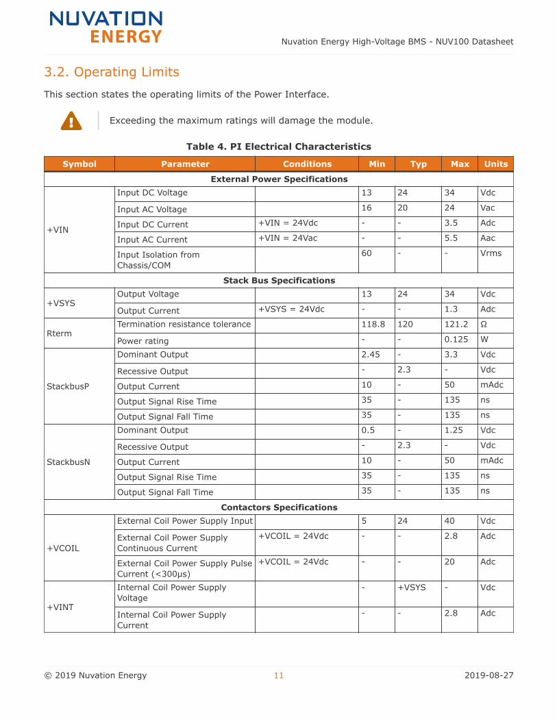
3.2. Operating Limits
This section states the operating limits of the Power Interface.
Exceeding the maximum ratings will damage the module.
Table 4. PI Electrical Characteristics
Symbol Parameter Conditions Min Typ Max Units
External Power Specifications
+VIN
Input DC Voltage 13 24 34 Vdc
Input AC Voltage 16 20 24 Vac
Input DC Current +VIN = 24Vdc - - 3.5 Adc
Input AC Current +VIN = 24Vac - - 5.5 Aac
Input Isolation from
Chassis/COM
60 - - Vrms
Stack Bus Specifications
+VSYSOutput Voltage 13 24 34 Vdc
Output Current +VSYS = 24Vdc - - 1.3 Adc
RtermTermination resistance tolerance 118.8 120 121.2 Ω
Power rating - - 0.125 W
StackbusP
Dominant Output 2.45 - 3.3 Vdc
Recessive Output - 2.3 - Vdc
Output Current 10 - 50 mAdc
Output Signal Rise Time 35 - 135 ns
Output Signal Fall Time 35 - 135 ns
StackbusN
Dominant Output 0.5 - 1.25 Vdc
Recessive Output - 2.3 - Vdc
Output Current 10 - 50 mAdc
Output Signal Rise Time 35 - 135 ns
Output Signal Fall Time 35 - 135 ns
Contactors Specifications
+VCOIL
External Coil Power Supply Input 5 24 40 Vdc
External Coil Power Supply
Continuous Current
+VCOIL = 24Vdc - - 2.8 Adc
External Coil Power Supply Pulse
Current (<300µs)
+VCOIL = 24Vdc - - 20 Adc
+VINT
Internal Coil Power Supply
Voltage
- +VSYS - Vdc
Internal Coil Power Supply
Current
- - 2.8 Adc
Nuvation Energy High-Voltage BMS - NUV100 Datasheet
© 2019 Nuvation Energy 11 2019-08-27
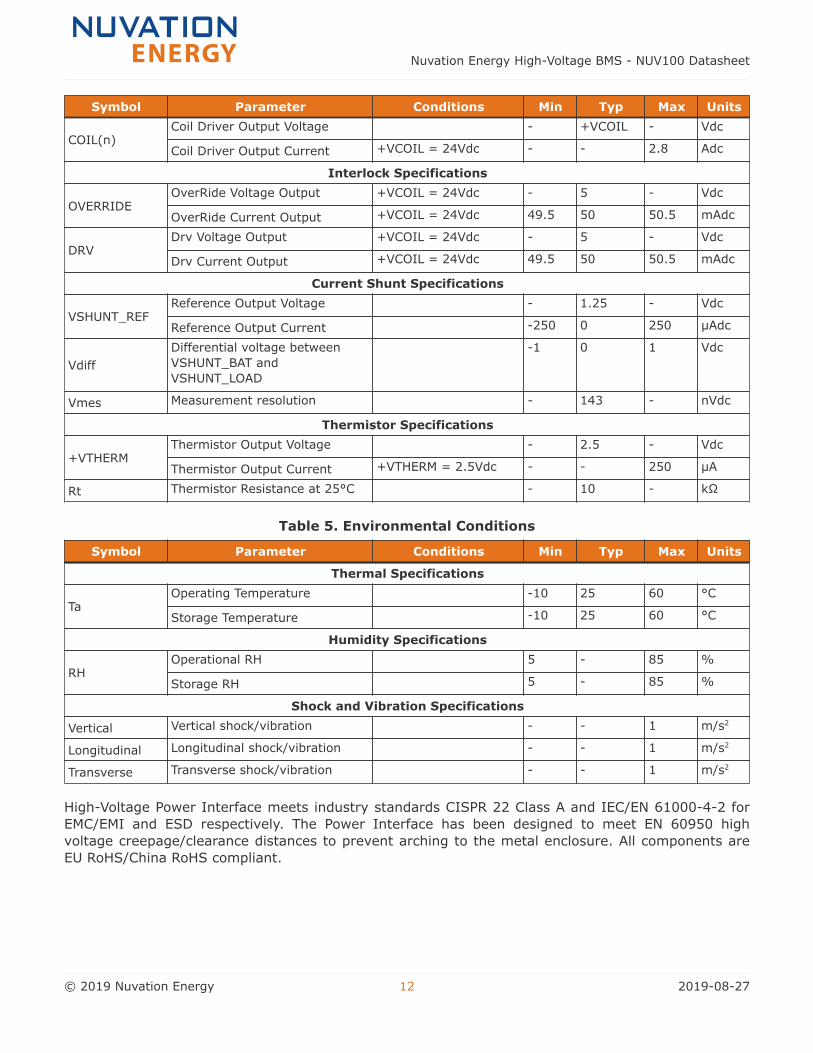
Symbol Parameter Conditions Min Typ Max Units
COIL(n)Coil Driver Output Voltage - +VCOIL - Vdc
Coil Driver Output Current +VCOIL = 24Vdc - - 2.8 Adc
Interlock Specifications
OVERRIDEOverRide Voltage Output +VCOIL = 24Vdc - 5 - Vdc
OverRide Current Output +VCOIL = 24Vdc 49.5 50 50.5 mAdc
DRVDrv Voltage Output +VCOIL = 24Vdc - 5 - Vdc
Drv Current Output +VCOIL = 24Vdc 49.5 50 50.5 mAdc
Current Shunt Specifications
VSHUNT_REFReference Output Voltage - 1.25 - Vdc
Reference Output Current -250 0 250 µAdc
Vdiff
Differential voltage between
VSHUNT_BAT and
VSHUNT_LOAD
-1 0 1 Vdc
Vmes Measurement resolution - 143 - nVdc
Thermistor Specifications
+VTHERMThermistor Output Voltage - 2.5 - Vdc
Thermistor Output Current +VTHERM = 2.5Vdc - - 250 µA
Rt Thermistor Resistance at 25°C - 10 - kΩ
Table 5. Environmental Conditions
Symbol Parameter Conditions Min Typ Max Units
Thermal Specifications
TaOperating Temperature -10 25 60 °C
Storage Temperature -10 25 60 °C
Humidity Specifications
RHOperational RH 5 - 85 %
Storage RH 5 - 85 %
Shock and Vibration Specifications
Vertical Vertical shock/vibration - - 1 m/s2
Longitudinal Longitudinal shock/vibration - - 1 m/s2
Transverse Transverse shock/vibration - - 1 m/s2
High-Voltage Power Interface meets industry standards CISPR 22 Class A and IEC/EN 61000-4-2 for
EMC/EMI and ESD respectively. The Power Interface has been designed to meet EN 60950 high
voltage creepage/clearance distances to prevent arching to the metal enclosure. All components are
EU RoHS/China RoHS compliant.
Nuvation Energy High-Voltage BMS - NUV100 Datasheet
© 2019 Nuvation Energy 12 2019-08-27
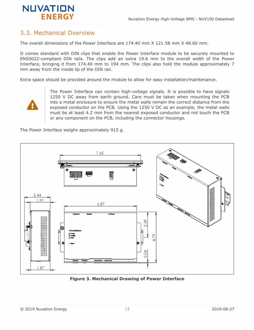
3.3. Mechanical Overview
The overall dimensions of the Power Interface are 174.40 mm X 121.58 mm X 48.60 mm.
It comes standard with DIN clips that enable the Power Interface module to be securely mounted to
EN50022-compliant DIN rails. The clips add an extra 19.6 mm to the overall width of the Power
Interface, bringing it from 174.40 mm to 194 mm. The clips also hold the module approximately 7
mm away from the inside lip of the DIN rail.
Extra space should be provided around the module to allow for easy installation/maintenance.
The Power Interface can contain high-voltage signals. It is possible to have signals
1250 V DC away from earth ground. Care must be taken when mounting the PCB
into a metal enclosure to ensure the metal walls remain the correct distance from the
exposed conductor on the PCB. Using the 1250 V DC as an example, the metal walls
must be at least 4.2 mm from the nearest exposed conductor and not touch the PCB
or any component on the PCB, including the connector housings.
The Power Interface weighs approximately 915 g.
Figure 3. Mechanical Drawing of Power Interface
Nuvation Energy High-Voltage BMS - NUV100 Datasheet
© 2019 Nuvation Energy 13 2019-08-27
4. Nuvation Energy Cell Interface
The Nuvation Energy High-Voltage BMS system requires one or more Nuvation Energy Cell Interface
modules to monitor its battery stack cells.
For information regarding the Nuvation Energy Cell Interface, please refer to Nuvation Energy Cell
Interface: NUV100-CI Datasheet available online at https://www.nuvationenergy.com/technical-
resources.
Nuvation Energy High-Voltage BMS - NUV100 Datasheet
© 2019 Nuvation Energy 14 2019-08-27
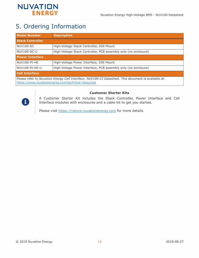
5. Ordering Information
Model Number Description
Stack Controller
NUV100-SC High-Voltage Stack Controller, DIN Mount
NUV100-SC-U High-Voltage Stack Controller, PCB assembly only (no enclosure)
Power Interface
NUV100-PI-HE High-Voltage Power Interface, DIN Mount
NUV100-PI-HE-U High-Voltage Power Interface, PCB assembly only (no enclosure)
Cell Interface
Please refer to Nuvation Energy Cell Interface: NUV100-CI Datasheet. This document is available at:
https://www.nuvationenergy.com/technical-resources
Customer Starter Kits
A Customer Starter Kit includes the Stack Controller, Power Interface and Cell
Interface modules with enclosures and a cable kit to get you started.
Please visit https://nstore.nuvationenergy.com for more details.
Nuvation Energy High-Voltage BMS - NUV100 Datasheet
© 2019 Nuvation Energy 15 2019-08-27
From time to time Nuvation Energy will make updates to the Nuvation Energy BMS in response to
changes in available technologies, client requests, emerging energy storage standards, and other
industry requirements. The product specifications in this document, therefore, are subject to change
without notice.
© 2019 Nuvation Energy
Nuvation Energy High-Voltage BMS - NUV100 Datasheet
© 2019 Nuvation Energy 16 2019-08-27