Embed Size (px)
Citation preview
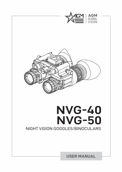
USER MANUAL
NVG-40NVG-50
NIGHT VISION GOGGLES/BINOCULARS
© 2021 AGM Global Vision, LLC. All rights reserved.
This documentation is subject to change without notice.
No parts of this manual, in whole or in part, may be copied, photocopied, translated, or transmitted by any electronic medium or in machine-readable form without the prior written permission of AGM Global Vision, LLC.
Approved for public release, distribution unlimited.
If you have questions that are not covered in this manual, or need service, contact AGM Global Vision customer support for additional information prior to returning a product.
AGM Global Vision, LLC
173 West Main StreetPO Box 962Springerville, AZ 85938Tel. [email protected]
EXPORT INFORMATION
Buyer acknowledges that all products supplied by AGM Global Vision, LLC are subject to U.S. export control laws, including, but not limited to, the Export Administration Regulations, the International Economic Emergency Powers Act, and various U.S. embargoes and sanctions. AGM Global Vision products may not be exported, re-exported, or transferred contrary to U.S. export control laws. In particular, AGM Global Vision products may not be exported, re-exported, or transferred to prohibited countries, individuals, organizations, or entities, including but not limited to those individuals and entities listed on the List of Specially Designated Nationals and Blocked Persons administered or maintained by the U.S. Office of Foreign Assets Control (“OFAC”), the various lists maintained by the Bureau of Industry and Security of the Department of Commerce, and the U.S. State Department and Buyer represents and warrants that neither Buyer nor any of its officers, directors, or employees are on such lists. Distribution or resale by Buyer to such countries, individuals, organizations, or entities is expressly prohibited. Buyer has and will maintain a positive process to ensure compliance with this Section.
2021.05.12
3NVG-40 / NVG-50 USER MANUAL
LIST OF CONTENTS
TITLE PAGE
Safety Summary 4SECTION 1. GENERAL INFORMATION 61.1 System Description 61.2 Key Features 71.3 Standard Components 81.4 Optional Equipment 9SECTION 2. OPERATING INSTRUCTIONS 102.1 Installation and Mounting 102.2 System Controls 112.3 Operating Procedures 13SECTION 3. MAINTENANCE 223.1 Maintenance 22SECTION 4. WARRANTY INFORMATION 244.1 Warranty Information and Registration 24SECTION 5. SPECIFICATIONS 275.1 Specifications 27APPENDIX 29A. Spare Parts List 29
4 AGM Global Vision
SAFETY SUMMARY
• Read and follow all instructions• Read all warnings• Only use the attachments/accessories specified by the manufacturer• All service must be provided by the manufacturer
WARNING:
This product contains natural rubber latex, which may cause potentially fatal allergic reactions! If you are allergic to latex, it is important that you strictly avoid exposure to products that contain it.
WARNINGS:
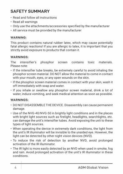
The intensifier’s phosphor screen contains toxic materials. Please note:• If the intensifier tube breaks, be extremely careful to avoid inhaling the
phosphor screen material. DO NOT allow the material to come in contact with your mouth, eyes, or any open wounds on the skin.
• If the phosphor screen material comes in contact with your skin, wash it off immediately with soap and water.
• If you inhale or swallow any phosphor screen material, drink a lot of water, induce vomiting, and seek medical attention as soon as possible.
WARNINGS:
• DO NOT DISASSEMBLE THE DEVICE. Disassembly can cause permanent damage.
• Use of the NVG-40/NVG-50 in brightly light conditions and in the places with bright light sources such as firelight, headlights, searchlights, etc. can damage the unit’s intensifier tubes. Avoid exposing the unit to these types of light sources.
• When operating the device in extremely dark conditions, the light from the unit’s IR illuminator will be invisible to the unaided eye. However, the light can be detected by other night vision devices (NVD).
• To reduce the risk of detection by another NVD, avoid prolonged activation of the IR illuminator.
• The IR light is more easily detected by an NVD when used in smoke, fog and rain. Avoid prolonged activation of the unit’s IR illuminator in these conditions.
5NVG-40 / NVG-50 USER MANUAL
CAUTIONS:
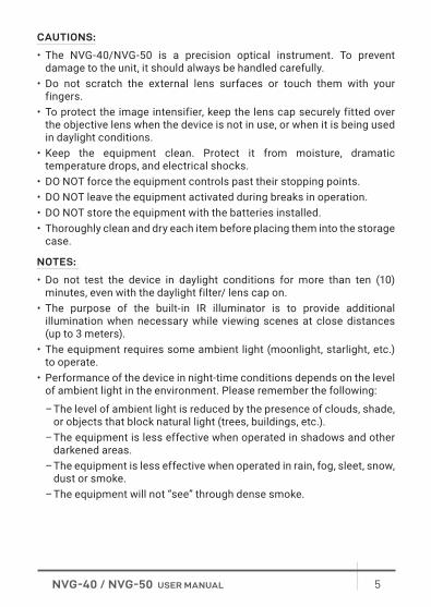
• The NVG-40/NVG-50 is a precision optical instrument. To prevent damage to the unit, it should always be handled carefully.
• Do not scratch the external lens surfaces or touch them with your fingers.
• To protect the image intensifier, keep the lens cap securely fitted over the objective lens when the device is not in use, or when it is being used in daylight conditions.
• Keep the equipment clean. Protect it from moisture, dramatic temperature drops, and electrical shocks.
• DO NOT force the equipment controls past their stopping points.• DO NOT leave the equipment activated during breaks in operation.• DO NOT store the equipment with the batteries installed.• Thoroughly clean and dry each item before placing them into the storage
case.
NOTES:
• Do not test the device in daylight conditions for more than ten (10) minutes, even with the daylight filter/ lens cap on.
• The purpose of the built-in IR illuminator is to provide additional illumination when necessary while viewing scenes at close distances (up to 3 meters).
• The equipment requires some ambient light (moonlight, starlight, etc.) to operate.
• Performance of the device in night-time conditions depends on the level of ambient light in the environment. Please remember the following:
– The level of ambient light is reduced by the presence of clouds, shade, or objects that block natural light (trees, buildings, etc.).
– The equipment is less effective when operated in shadows and other darkened areas.
– The equipment is less effective when operated in rain, fog, sleet, snow, dust or smoke.
– The equipment will not “see” through dense smoke.
6 AGM Global Vision
1 GENERAL INFORMATION
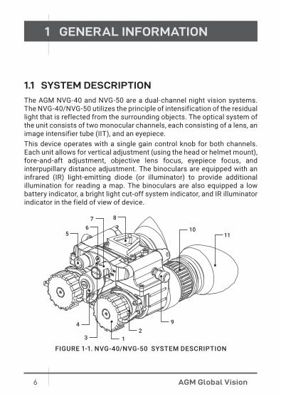
1.1 SYSTEM DESCRIPTION
The AGM NVG-40 and NVG-50 are a dual-channel night vision systems. The NVG-40/NVG-50 utilizes the principle of intensification of the residual light that is reflected from the surrounding objects. The optical system of the unit consists of two monocular channels, each consisting of a lens, an image intensifier tube (IIT), and an eyepiece. This device operates with a single gain control knob for both channels. Each unit allows for vertical adjustment (using the head or helmet mount), fore-and-aft adjustment, objective lens focus, eyepiece focus, and interpupillary distance adjustment. The binoculars are equipped with an infrared (IR) light-emitting diode (or illuminator) to provide additional illumination for reading a map. The binoculars are also equipped a low battery indicator, a bright light cut-off system indicator, and IR illuminator indicator in the field of view of device.
29
13
4
56
7 8
1011
FIGURE 1-1. NVG-40/NVG-50 SYSTEM DESCRIPTION
7NVG-40 / NVG-50 USER MANUAL
TABLE 1-1. NVG-40/NVG-50 SYSTEM DESCRIPTION
ITEM DESCRIPTION ITEM DESCRIPTION
1 Lens Cap 7 Turn-Pull Operating Switch2 Focus Ring 8 Mounting Bracket3 Photoreceiver
9 Interpupillary Distance Adjustment Knob4 Battery Cap
5 Gain Control Knob 10 Diopter Adjustment Ring
6 Built-In IR Illuminator 11 Eyepiece
1.2 KEY FEATURES
• Rotating binocular design allows low profile against helmet when in stowed position and ability to use as a single monocular
• Binocular design for sustained viewing periods and improved depth perception
• Manual system gain and focus adjustments for custom image qual-ity optimization
• Auto OFF when stowed; resumes power when deployed
• Integrated infrared (IR) illuminator
• Head or helmet-mountable
• Low-battery, bright light cut-off, and IR indicators in eyepiece
• Self-contained system operating on a single AA or CR123 battery
• Optional remote battery pack for extended use
• Limited 3-year warranty
8 AGM Global Vision
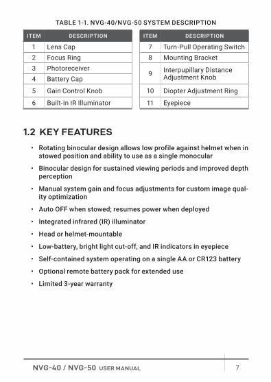
1.3 STANDARD COMPONENTSThe standard components of the NVG-40/NVG-50 are shown in Figure 1-2 and listed in Table 1-2.The ITEM column indicates the number used to identify items in Figure 1-2.
TABLE 1-2. NVG-40/NVG-50 STANDARD COMPONENTS
ITEM DESCRIPTION QUANTITY
1 Night Vision Binocular 12 Lens Cap 13 Mounting Bracket (preinstalled NVG Interface Shoe) 14 Eyecup 15 Demist Shield 26 Sacrificial Window 27 Bayonet/Horn Interface Shoe 18 Battery 19 Lens Cloth 1
10 User Manual 1
11 Soft Carrying Case 1
FIGURE 1-2. NVG-40/NVG-50 STANDARD COMPONENTS
2 1
3 4
89
10
6
11
5 7
9NVG-40 / NVG-50 USER MANUAL
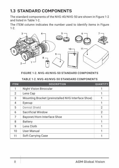
1.4 OPTIONAL EQUIPMENT
The optional equipment of the NVG-40/NVG-50 is shown in Figure 1-3 and listed in Table 1-3.The ITEM column indicates the number used to identify items in Figure 1-3.
TABLE 1-3. NVG-40/NVG-50 OPTIONAL EQUIPMENT
ITEM DESCRIPTION PART NO.
1 Battery Pack 6108BPA1
2Battery Pack Kit G50 (comes included with Battery Pack, NVG Interface Shoe with Connector, Velcro® Battery Case Holder)
6108EBP1
3 Battery Locking Plate Adapter 6108BLP14 NVG Interface Shoe with Connector 6108ISC15 Mini-Rail Interface Shoe 6506MRN16 Goggle Kit W-G50 6104GK51
7 Helmet Mount G50MP for MICH and PASGT Helmets 6103HM51
8 Helmet Mount G50S for Shroud 6103HS51
9Sioux850-W kit (includes Sioux850 Long-Range Infrared Illuminator, Mount, Adapter, Rechargeable Battery and Charger)
501SIOUW850IR1
10 Hard Case for Storage/Transportation 6610HCS1
FIGURE 1-3. NVG-40/NVG-50 OPTIONAL EQUIPMENT
109
1 2 3 4 65
7 8
10 AGM Global Vision
2 OPERATING INSTRUCTIONS
2.1. INSTALLATION AND MOUNTING
CAUTION:
To protect the intensifier tube when the sight is not in use or when it is being operated in daylight, keep the protective lens cap securely fitted over the lens.
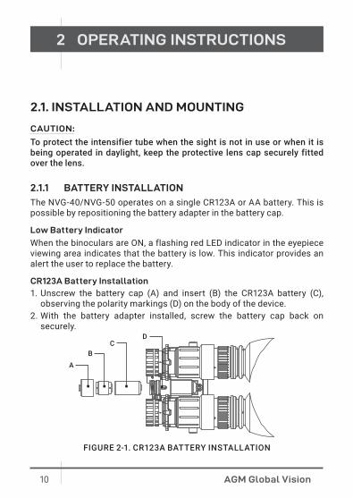
2.1.1 BATTERY INSTALLATION
The NVG-40/NVG-50 operates on a single CR123A or AA battery. This is possible by repositioning the battery adapter in the battery cap.
Low Battery Indicator
When the binoculars are ON, a flashing red LED indicator in the eyepiece viewing area indicates that the battery is low. This indicator provides an alert the user to replace the battery.
CR123A Battery Installation
1. Unscrew the battery cap (A) and insert (B) the CR123A battery (C), observing the polarity markings (D) on the body of the device.
2. With the battery adapter installed, screw the battery cap back on securely.
FIGURE 2-1. CR123A BATTERY INSTALLATION
A
DC
B
11NVG-40 / NVG-50 USER MANUAL
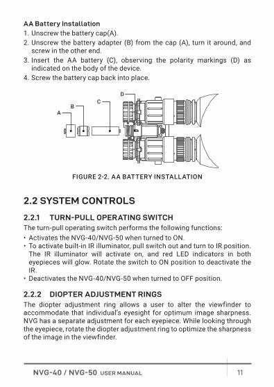
AA Battery Installation
1. Unscrew the battery cap(A). 2. Unscrew the battery adapter (B) from the cap (A), turn it around, and
screw in the other end.3. Insert the AA battery (C), observing the polarity markings (D) as
indicated on the body of the device.4. Screw the battery cap back into place.
2.2 SYSTEM CONTROLS
2.2.1 TURN-PULL OPERATING SWITCHThe turn-pull operating switch performs the following functions:• Activates the NVG-40/NVG-50 when turned to ON.• To activate built-in IR illuminator, pull switch out and turn to IR position.
The IR illuminator will activate on, and red LED indicators in both eyepieces will glow. Rotate the switch to ON position to deactivate the IR.
• Deactivates the NVG-40/NVG-50 when turned to OFF position.
2.2.2 DIOPTER ADJUSTMENT RINGSThe diopter adjustment ring allows a user to alter the viewfinder to accommodate that individual’s eyesight for optimum image sharpness. NVG has a separate adjustment for each eyepiece. While looking through the eyepiece, rotate the diopter adjustment ring to optimize the sharpness of the image in the viewfinder.
FIGURE 2-2. AA BATTERY INSTALLATION
A
DC
B
12 AGM Global Vision
2.2.3 FOCUS RINGBring the object into focus by turning the objective focus ring (counter clockwise for far focus, clockwise for near focus, if you look in the eyepieces). Rotate the focus ring until the subject looks sharp in the viewfinder.
2.2.4 INTERPUPILLARY DISTANCE KNOB ADJUSTMENTAdjusts the distance between each eyepiece by rotating the knobs together or apart, allowing for each eye to observe the entire field at the same time.
2.2.5 GAIN CONTROL KNOBUsed to adjust the gain (brightness) of the viewed image. Turn the gain control to balance the illumination input to the eyes.
2.2.6 INDICATIONWhen the NVG-40/NVG-50 is ON, the color LED indicators can be shown in the field of view. The color LEDs indicate the following states of the device:
INDICATIONS COLOR OF LED IN THE FOV
Built-in IR illuminator is activated RedImage intensifier tubes are exposed to excessive levels of light Green
Battery is low Flashing Red
2.2.7 AUTO POWER OFF FUNCTION
The NVG-40/NVG-50 bright light cut-off feature shuts off power to the binoculars when they are exposed to excessive levels of light for more than 10 seconds. Automatic shut-off system automatically turns off the device when it is unused (controls are not touched) for 60 minutes. The automatic shut-off function preserves battery life should the device be inadvertently activated.
13NVG-40 / NVG-50 USER MANUAL
2.3 PROCEDURES
2.3.1 OPERATING PROCEDURES
1. Verify that the battery is installed as indicated on the unit body.
NOTE:
Only operate the binocular in dark environments. If it necessary to operate the device in daylight, use the objective lens caps to cover the objective lenses. The pinhole at the center of the lens caps allows to check the operation ability of the device in daylight conditions.
2. Remove the lens cap and place it over the housing of the lens.3. Turn the function switch ON. After a slight delay, a green or white glow
will appear in the eyepiece of the unit.4. Adjust the unit diopter by rotating the ring of the eyepiece.5. Observe the scene. Rotate the focus ring until the image is clear and
sharp.6. Adjust the brightness of the image using the gain control knob.
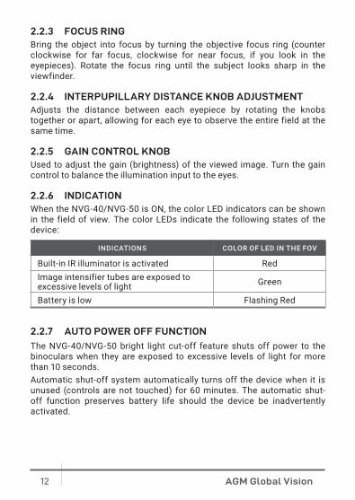
The NVG-40/NVG-50 can be used as one-eye observational unit by choosing which side you want to use as your night vision monocular and rotate the other unit up and out of the way. The power of unit will be switched off in rotated up position and it will be on automatically when returned back to the working position.
STOWED POSITIONMONOCULAR GOGGLES POSITION
FIGURE 2-3. NVG POSITION
14 AGM Global Vision
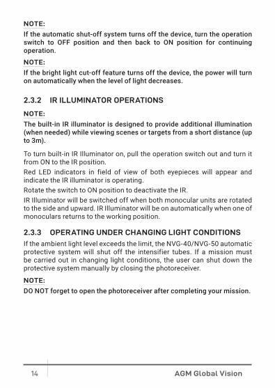
NOTE:
If the automatic shut-off system turns off the device, turn the operation switch to OFF position and then back to ON position for continuing operation.
NOTE:
If the bright light cut-off feature turns off the device, the power will turn on automatically when the level of light decreases.
2.3.2 IR ILLUMINATOR OPERATIONS
NOTE:
The built-in IR illuminator is designed to provide additional illumination (when needed) while viewing scenes or targets from a short distance (up to 3m).
To turn built-in IR Illuminator on, pull the operation switch out and turn it from ON to the IR position.Red LED indicators in field of view of both eyepieces will appear and indicate the IR illuminator is operating. Rotate the switch to ON position to deactivate the IR.IR Illuminator will be switched off when both monocular units are rotated to the side and upward. IR Illuminator will be on automatically when one of monoculars returns to the working position.
2.3.3 OPERATING UNDER CHANGING LIGHT CONDITIONS
If the ambient light level exceeds the limit, the NVG-40/NVG-50 automatic protective system will shut off the intensifier tubes. If a mission must be carried out in changing light conditions, the user can shut down the protective system manually by closing the photoreceiver.
NOTE:
DO NOT forget to open the photoreceiver after completing your mission.
15NVG-40 / NVG-50 USER MANUAL
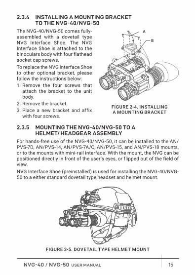
2.3.4 INSTALLING A MOUNTING BRACKET TO THE NVG-40/NVG-50
The NVG-40/NVG-50 comes fully-assembled with a dovetail type NVG Interface Shoe. The NVG Interface Shoe is attached to the binoculars body with four flathead socket cap screws.To replace the NVG Interface Shoe to other optional bracket, please follow the instructions below:1. Remove the four screws that
attach the bracket to the unit body.
2. Remove the bracket.3. Place a new bracket and affix
with four screws.
2.3.5 MOUNTING THE NVG-40/NVG-50 TO A HELMET/ HEADGEAR ASSEMBLY
For hands-free use of the NVG-40/NVG-50, it can be installed to the AN/PVS-7D, AN/PVS-14, AN/PVS-7A/C, AN/PVS-15, and AN/PVS-18 mounts, or to the mounts with mini-rail interface. With the mount, the NVG can be positioned directly in front of the user’s eyes, or flipped out of the field of view.NVG Interface Shoe (preinstalled) is used for installing the NVG-40/NVG-50 to a either standard dovetail type headset and helmet mount.
A
B
FIGURE 2-4. INSTALLING A MOUNTING BRACKET
FIGURE 2-5. DOVETAIL TYPE HELMET MOUNT
16 AGM Global Vision
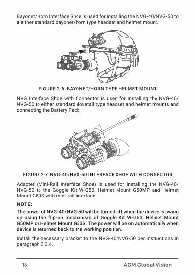
Bayonet/Horn Interface Shoe is used for installing the NVG-40/NVG-50 to a either standard bayonet/horn type headset and helmet mount.
NVG Interface Shoe with Connector is used for installing the NVG-40/NVG-50 to either standard dovetail type headset and helmet mounts and connecting the Battery Pack.
Adapter (Mini-Rail Interface Shoe) is used for installing the NVG-40/ NVG-50 to the Goggle Kit W-G50, Helmet Mount G50MP and Helmet Mount G50S with mini-rail interface.
NOTE:
The power of NVG-40/NVG-50 will be turned off when the device is swing up using the flip-up mechanism of Goggle Kit W-G50, Helmet Mount G50MP or Helmet Mount G50S. The power will be on automatically when device is returned back to the working position.
Install the necessary bracket to the NVG-40/NVG-50 per instructions in paragraph 2.3.4.
FIGURE 2-6. BAYONET/HORN TYPE HELMET MOUNT
FIGURE 2-7. NVG-40/NVG-50 INTERFACE SHOE WITH CONNECTOR
17NVG-40 / NVG-50 USER MANUAL
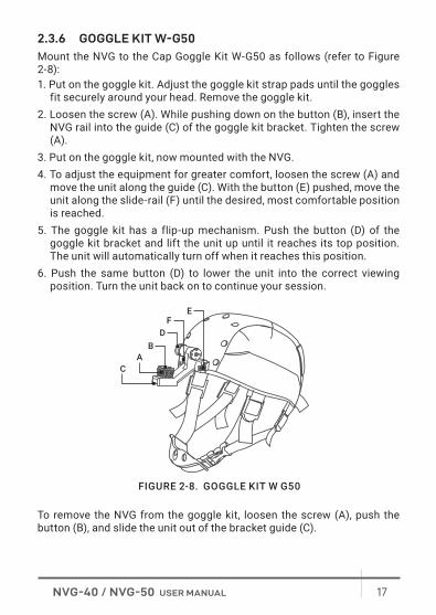
2.3.6 GOGGLE KIT W-G50
Mount the NVG to the Cap Goggle Kit W-G50 as follows (refer to Figure 2-8):1. Put on the goggle kit. Adjust the goggle kit strap pads until the goggles
fit securely around your head. Remove the goggle kit.2. Loosen the screw (A). While pushing down on the button (B), insert the
NVG rail into the guide (C) of the goggle kit bracket. Tighten the screw (A).
3. Put on the goggle kit, now mounted with the NVG.4. To adjust the equipment for greater comfort, loosen the screw (A) and
move the unit along the guide (C). With the button (E) pushed, move the unit along the slide-rail (F) until the desired, most comfortable position is reached.
5. The goggle kit has a flip-up mechanism. Push the button (D) of the goggle kit bracket and lift the unit up until it reaches its top position. The unit will automatically turn off when it reaches this position.
6. Push the same button (D) to lower the unit into the correct viewing position. Turn the unit back on to continue your session.
To remove the NVG from the goggle kit, loosen the screw (A), push the button (B), and slide the unit out of the bracket guide (C).
C
FE
D
AB
FIGURE 2-8. GOGGLE KIT W G50
18 AGM Global Vision
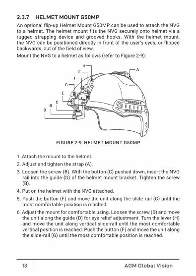
2.3.7 HELMET MOUNT G50MP
An optional flip-up Helmet Mount G50MP can be used to attach the NVG to a helmet. The helmet mount fits the NVG securely onto helmet via a rugged strapping device and grooved hooks. With the helmet mount, the NVG can be positioned directly in front of the user’s eyes, or flipped backwards, out of the field of view.Mount the NVG to a helmet as follows (refer to Figure 2-9):
1. Attach the mount to the helmet.2. Adjust and tighten the strap (A).3. Loosen the screw (B). With the button (C) pushed down, insert the NVG
rail into the guide (D) of the helmet mount bracket. Tighten the screw (B).
4. Put on the helmet with the NVG attached.5. Push the button (F) and move the unit along the slide-rail (G) until the
most comfortable position is reached.6. Adjust the mount for comfortable using. Loosen the screw (B) and move
the unit along the guide (D) for eye relief adjustment. Turn the lever (H) and move the unit along vertical slide-rail until the most comfortable vertical position is reached. Push the button (F) and move the unit along the slide-rail (G) until the most comfortable position is reached.
AH
G
FI
CB
D
E
FIGURE 2-9. HELMET MOUNT G50MP
19NVG-40 / NVG-50 USER MANUAL
7. To remove the NVG and turn it around, push the button down (E) and lift the unit up until it reaches the top position. Once it reaches this position, the unit will turn off automatically.
8. Push the same button (E) to lower the NVG into the proper viewing position. Turn the unit on to proceed with your mission.
To remove the NVG from the helmet mount, loosen the screw (B), push down on the button (C), and slide the unit out of the guide (D). To remove the flip-up mechanism from the helmet mount, loosen the lever (H), pull the knob out (I), and slide the flip-up mechanism out of the vertical rail.
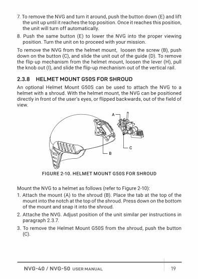
2.3.8 HELMET MOUNT G50S FOR SHROUD
An optional Helmet Mount G50S can be used to attach the NVG to a helmet with a shroud. With the helmet mount, the NVG can be positioned directly in front of the user’s eyes, or flipped backwards, out of the field of view.
Mount the NVG to a helmet as follows (refer to Figure 2-10):1. Attach the mount (A) to the shroud (B). Place the tab at the top of the
mount into the notch at the top of the shroud. Press down on the bottom of the mount and snap it into the shroud.
2. Attache the NVG. Adjust position of the unit similar per instructions in paragraph 2.3.7.
3. To remove the Helmet Mount G50S from the shroud, push the button (C).
FIGURE 2-10. HELMET MOUNT G50S FOR SHROUD
A
BC
20 AGM Global Vision
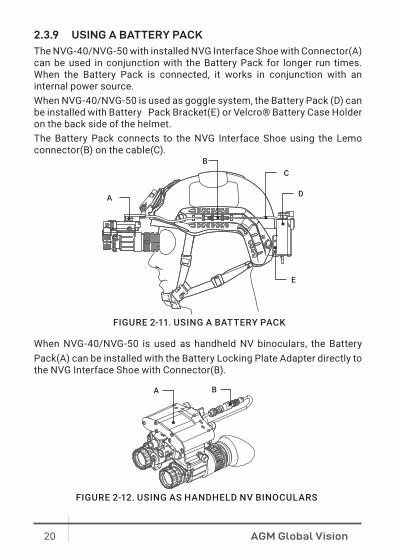
2.3.9 USING A BATTERY PACK
The NVG-40/NVG-50 with installed NVG Interface Shoe with Connector(A) can be used in conjunction with the Battery Pack for longer run times. When the Battery Pack is connected, it works in conjunction with an internal power source. When NVG-40/NVG-50 is used as goggle system, the Battery Pack (D) can be installed with Battery Pack Bracket(E) or Velcro® Battery Case Holder on the back side of the helmet.The Battery Pack connects to the NVG Interface Shoe using the Lemo connector(B) on the cable(C).
When NVG-40/NVG-50 is used as handheld NV binoculars, the Battery Pack(A) can be installed with the Battery Locking Plate Adapter directly to the NVG Interface Shoe with Connector(B).
A
BC
D
E
FIGURE 2-11. USING A BATTERY PACK
FIGURE 2-12. USING AS HANDHELD NV BINOCULARS
A B
21NVG-40 / NVG-50 USER MANUAL
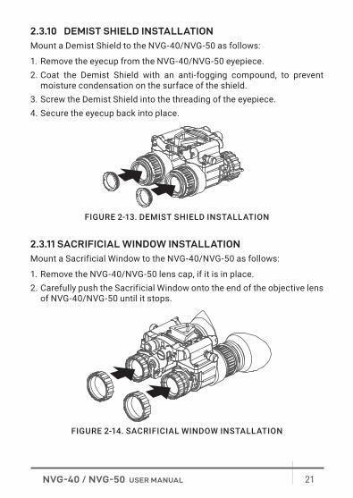
2.3.10 DEMIST SHIELD INSTALLATION
Mount a Demist Shield to the NVG-40/NVG-50 as follows:
1. Remove the eyecup from the NVG-40/NVG-50 eyepiece.2. Coat the Demist Shield with an anti-fogging compound, to prevent
moisture condensation on the surface of the shield.3. Screw the Demist Shield into the threading of the eyepiece.4. Secure the eyecup back into place.
2.3.11 SACRIFICIAL WINDOW INSTALLATION
Mount a Sacrificial Window to the NVG-40/NVG-50 as follows:
1. Remove the NVG-40/NVG-50 lens cap, if it is in place.2. Carefully push the Sacrificial Window onto the end of the objective lens
of NVG-40/NVG-50 until it stops.
FIGURE 2-13. DEMIST SHIELD INSTALLATION
FIGURE 2-14. SACRIFICIAL WINDOW INSTALLATION
22 AGM Global Vision
3 MAINTENANCE INSTRUCTIONS
3.1 MAINTENANCE
3.1.1 BATTERY REMOVAL AND REPLACEMENT
Refer to Part 2.1 for battery installation procedures.
3.1.2 CLEANING THE NVG-40/NVG-50
Wipe the housing with a damp cloth as needed.
CAUTION:
Do not use abrasives or solvents to clean the housing, lens, or display window. Do not use ammonia-based cleaning products to clean the lens. Doing so may damage the anti-reflective coating of the lens
The NVG-40/NVG-50 lens is designed for the harsh outdoor environment and has a coating for durability and anti-reflection, but it may require cleaning occasionally. Avoid scratching the lens and/or leaving fingerprints on the optics. Optics can be damaged by improper cleaning. Clean the lens according to the instructions below when image quality degradation is noticed or excessive dirt or other contaminant is on the lens.Do not use abrasive materials, such as paper or scrub brushes as this will possibly damage the lens by scratching it. Only wipe the lens clean when there is visible contamination on the surface.
23NVG-40 / NVG-50 USER MANUAL
PREFERRED METHOD FOR CLEANING THE LENS
Materials:• Optical-grade cloth• Pure water (de-ionized or other)• Isopropyl alcohol (IPA)
Saturate a piece of the lens tissue with the water and drape it over the lens. Let the surface tension of the water pull the tissue onto the lens surface and then drag the tissue across the lens surface. Repeat several times with different pieces of tissue.Repeat the same step using IPA instead of water. Drag the final piece of tissue over the lens several times to prevent pooling, which could leave a residue behind.
24 AGM Global Vision
4 WARRANTY INFORMATION
4.1 WARRANTY INFORMATION AND REGISTRATION
4.1.1 WARRANTY INFORMATIONThis product is guaranteed to be free from manufacturing defects in material and workmanship under normal use for a period of three (3) years from the date of purchase. In the event that a defect covered by the warranty below occurs during the applicable period stated above, AGM Global Vision, at its discretion, will either repair or replace the product; such action on the part of AGM Global Vision shall be the full extent of AGM Global Vision’s liability, and the Customer’s sole and exclusive reparation. This warranty does not cover a product if it has been (a) used in ways other than its normal and customary manner; (b) subjected to misuse; (c) subjected to alterations, modifications or repairs by the Customer or by any party other than AGM Global Vision without prior written consent of AGM Global Vision; (d) is the result of a special order or categorized as “close-out” merchandise or merchandise sold “as-is” by either AGM Global Vision or the AGM Global Vision dealer; or (e) merchandise that has been discontinued by the manufacturer and either parts or replacement units are not available due to reasons beyond the control of AGM Global Vision. AGM Global Vision shall not be responsible for any defects or damage that in AGM Global Vision’s view are a result from the mishandling, abuse, misuse, improper storage or improper operation of the device, including use in conjunction with equipment that is electrically or mechanically incompatible with, or of inferior quality to, the product, as well as failure to maintain the environmental conditions specified by the manufacturer. This warranty is extended only to the original purchaser. Any breach of this warranty shall be enforced unless the customer notifies AGM Global Vision at the address noted below within the applicable warranty period.The customer understands and agrees that except for the foregoing warranty, no other warranties written or oral, statutory, expressed or
25NVG-40 / NVG-50 USER MANUAL
implied, including any implied warranty of merchantability or fitness for a particular purpose, shall apply to the product. All such implied warranties are hereby and expressly disclaimed.
4.1.2 LIMITATION OF LIABILITYAGM Global Vision will not be liable for any claims, actions, suits, proceedings, costs, expenses, damages, or liabilities arising out of the use of this product. Operation and use of the product are the sole responsibility of the Customer. AGM Global Vision’s sole undertaking is limited to providing the products and services outlined herein in accordance with the terms and conditions of this Agreement. The provision of products sold and services performed by AGM Global Vision to the Customer shall not be interpreted, construed, or regarded, either expressly or implied, as being for the benefit of or creating any obligation toward any third party of legal entity outside AGM Global Vision and the Customer; AGM Global Vision’s obligations under this Agreement extend solely to the Customer. AGM Global Vision’s liability hereunder for damages, regardless of the form or action, shall not exceed the fees or other charges paid to AGM Global Vision by the customer or customer’s dealer. AGM Global Vision shall not, in any event, be liable for special, indirect, incidental, or consequential damages, including, but not limited to, lost income, lost revenue, or lost profit, whether such damages were foreseeable or not at the time of purchase, and whether or not such damages arise out of a breach of warranty, a breach of agreement, negligence, strict liability, or any other theory of liability.
4.1.3 PRODUCT REGISTRATIONIn order to validate the warranty on your product, the customer must complete and submit AGM Global Vision PRODUCT REGISTRATION FORM on our website (www.agmglobalvision.com/customer-support).
4.1.4 OBTAINING WARRANTY SERVICETo obtain warranty service on your unit, the End-user (Customer) must notify the AGM Global Vision service department via e-mail. Send any requests to [email protected] to receive a Return Merchandise Authorization number (RMA). When returning any device, please take the product to your retailer, or send the product, postage paid and with a copy of your sales receipt, to AGM Global Vision’s service center at the address listed above. All merchandise must be fully insured with the correct postage; AGM Global Vision will not be responsible for
26 AGM Global Vision
improper postage or merchandise that becomes lost or damaged during shipment. When sending product back, please clearly write the RMA# on the outside of the shipping box. Please include a letter that indicates your RMA#, the Customer’s Name, a Return Address, reason for the return, contact information (valid telephone numbers and/or an e-mail address), and proof of purchase that will help us to establish the valid start date of the warranty. Product merchandise returns that do not have an RMA# listed may be refused, or a significant delay in processing may occur. Estimated Warranty service time is 10-20 business days. The End-user/Customer is responsible for postage to AGM Global Vision for warranty service. AGM Global Vision will cover return postage/shipping after warranty repair to the End-user/Customer only if the product is covered by the aforementioned warranty. AGM Global Vision will return the product after warranty service by domestic UPS Ground service and/or domestic mail. Should any other requested, required, or international shipping methods be necessary, the postage/shipping fee will be the responsibility of the End-user/Customer.
For service, repair or replacement, please contact:
AGM Global Vision, LLC
173 West Main StreetPO Box 962Springerville, AZ 85938Tel. [email protected]
27NVG-40 / NVG-50 USER MANUAL
5 SPECIFICATIONS
5.1 SPECIFICATIONS
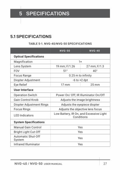
TABLE 5-1. NVG-40/NVG-50 SPECIFICATIONS
NVG-50 NVG-40
Optical Specifications
Magnification 1×Lens System 19 mm; F/1.26 27 mm; F/1.3FOV 51° 40°Focus Range 0.25 m to infinityDiopter Adjustment -6 to +2 dptEye Relief 17 mm 25 mm
User Interface
Operation Switch Power On/ Off; IR Illuminator On/OffGain Control Knob Adjusts the image brightnessDiopter Adjustment Rings Adjusts the eyepiece diopterFocus Rings Adjusts the objective lens focus
LED Indicators Low Battery, IR On, and Excessive Light Conditions
System Specifications
Manual Gain Control YesBright Light Cut-Off YesAutomatic Shut-Off System Yes
Infrared Illuminator Yes
28 AGM Global Vision
NVG-50 NVG-40
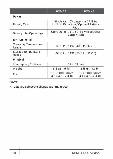
Power
Battery TypeSingle AA 1.5V battery or CR123A
Lithium 3V battery / Optional Battery Pack
Battery Life (Operating) Up to 20 hrs; up to 80 hrs with optional Battery Pack
Environmental
Operating Temperature Range -40°C to +50°C (-40°F to +122°F)
Storage Temperature Range -50°C to +50°C (-58°F to +122°F)
Physical
Interpupilary Distance 54 to 78 mmWeight 615 g (1.35 lb) 645 g (1.42 lb)
Size 115 × 118 × 73 mm (4.5 × 4.6 × 2.8 in)
113 × 118 × 73 mm (4.4 × 4.6 × 2.8 in)
NOTE:
All data are subject to change without notice.
29NVG-40 / NVG-50 USER MANUAL
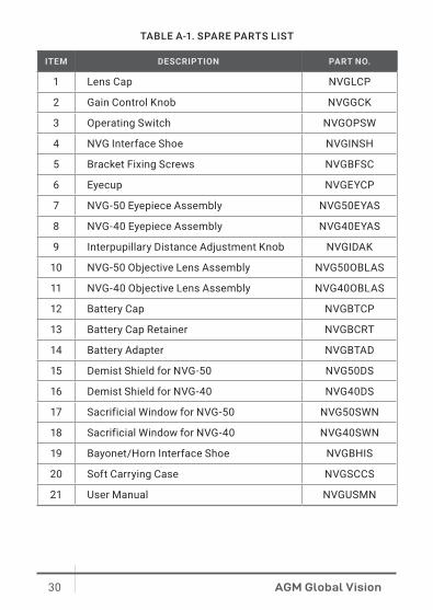
APPENDIX
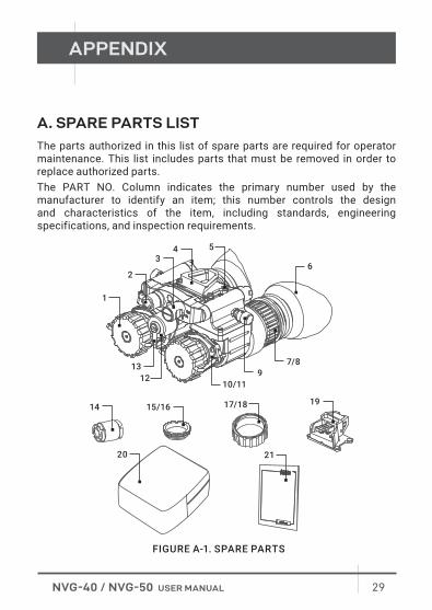
A. SPARE PARTS LIST
The parts authorized in this list of spare parts are required for operator maintenance. This list includes parts that must be removed in order to replace authorized parts.The PART NO. Column indicates the primary number used by the manufacturer to identify an item; this number controls the design and characteristics of the item, including standards, engineering specifications, and inspection requirements.
1
14 15/16 17/18 19
20 21
2
34 5
6
7/89
10/1112
13
FIGURE A-1. SPARE PARTS
30 AGM Global Vision
TABLE A-1. SPARE PARTS LIST
ITEM DESCRIPTION PART NO.
1 Lens Cap NVGLCP
2 Gain Control Knob NVGGCK
3 Operating Switch NVGOPSW
4 NVG Interface Shoe NVGINSH
5 Bracket Fixing Screws NVGBFSC
6 Eyecup NVGEYCP
7 NVG-50 Eyepiece Assembly NVG50EYAS
8 NVG-40 Eyepiece Assembly NVG40EYAS
9 Interpupillary Distance Adjustment Knob NVGIDAK
10 NVG-50 Objective Lens Assembly NVG50OBLAS
11 NVG-40 Objective Lens Assembly NVG40OBLAS
12 Battery Cap NVGBTCP
13 Battery Cap Retainer NVGBCRT
14 Battery Adapter NVGBTAD
15 Demist Shield for NVG-50 NVG50DS
16 Demist Shield for NVG-40 NVG40DS
17 Sacrificial Window for NVG-50 NVG50SWN
18 Sacrificial Window for NVG-40 NVG40SWN
19 Bayonet/Horn Interface Shoe NVGBHIS
20 Soft Carrying Case NVGSCCS
21 User Manual NVGUSMN

AGMglobalvision.com
AGM Global Vision, LLC
MAIN OFFICE
173 West Main Street
PO Box 962
Springerville, AZ 85938
USA
Tel. +1.928.333.4300
www.agmglobalvision.com
EUROPEAN OFFICE
Andrey Lyapchev #7
Sofia, P.C. 1756
Bulgaria
Tel. +35.988.412.5573
www.agmglobalvision.eu