Embed Size (px)
Citation preview
LANDTECHNIK 75(4), 2020, 301–315
NVH System Simulation of a Tractor with Hydrostatic-Mechanical Power Split TransmissionGerwin Pasch, Georg Jacobs, Joerg Berroth
The Noise, Vibration and Harshness (NVH) behaviour of vehicles is nowadays a key purchase criterion. Validated simulation methods are required to evaluate the NVH behaviour in the early phases of the product development process. This paper presents a methodology for model-based assessment of the NVH behaviour of a tractor with hydrostatic-mechanical pow-er split transmission (PST). The aim of the simulation methodology is the assessment of struc-ture-borne and airborne noise caused by transmission excitations. A multi-domain overall system model is proposed to accommodate numerous interactions and couplings within the system. The model combines the aspects of hydrostatic force excitation, structural dynamics and subsequent acoustic response. This paper introduces the main components of the sim-ulation model and demonstrates its application for a given standard tractor with PST. Simu-lation results of structure-borne and airborne noise for a wide operation range of the tractor are presented and compared with measurement results. The comparisons of simulation and measurement results show a high degree of conformity. The modelling method therefore allows identifying and optimising acoustic anomalies in the NVH behaviour even before proto-types and measurements at system level are available.
KeywordsNVH Tractor System Simulation, Structural Dynamics, Hydrostatic Excitations, Sound Radiation, Virtual Product Development
Hydrostatic-mechanical power split transmissions (PSTs) are widely used in tractor drivetrains (Re-nius 2003). They combine the customer requirements of high efficiency, realised by the mechanical transmission path, and a continuous variation of ratio without interrupting the traction force, which is realised through the hydrostatic transmission path. However, customer requirements regarding comfort issues arising from the Noise, Vibration and Harshness (NVH) behaviour have increased in recent years and have become an important development goal today (Krüger and Meyer 2015; Sie-mens 2018). Due to high energy density and discontinuous operation of the axial piston units inside the hydrostatic transmission path, PSTs cause strong tonal excitations. The excitation frequencies are proportional to the rotational speeds of the piston units. The excitations are transferred from the hydrostatic units via multiple structure-borne as well as airborne transfer paths to the driver’s ears inside the cabin. The airborne sound resulting from the tonal characteristic of the excitations in an acoustically relevant frequency range is perceived as particularly unpleasant for the driver and leads to reduced driving comfort (Jochum et al. 2013). Furthermore, the acoustic feedback from PSTs rarely corresponds to the experience of the driver, e. g. during an acceleration process of the vehicle.
DOI:10.15150/lt.2020.3254
received 12 June 2020 | accepted 17 December 2020 | published 23 December 2020© 2020 by the authors. This is an open access article distributed under the terms and conditions of the Creative Com-mons Attribution License (http://creativecommons.org/licenses/by/4.0).
LANDTECHNIK 75(4) 302
The driver typically associates an acceleration process with an acoustic feedback of increasing fre-quencies, as is common in most drive systems. In PSTs, however, due to the special interconnection structure, not only increasing but also decreasing excitation frequencies occur while accelerating caused by the hydrostatic units. In the case of dominant decreasing excitation frequencies during an acceleration process, the acoustic feedback can be confusing and annoying for the driver.
Decreasing development times necessitates methods that help reduce the probability of acoustic anomalies in earlier stages of the product development process. Virtual product development meth-ods offer the chance to assess the physical behaviour of the system even prior to prototyping stages (Vajna et al. 2018). As the NVH behaviour depends on the overall system characteristics, validated multi-domain simulation models at system level are required. Examples for multi-domain models that allow an overall view including excitation, sound transmission and sound radiation up to higher frequency ranges (2–5 kHz) can be found in the automotive sector. For example, a validated method-ology for a multi-domain model of an electrified car is described in (Drichel et al. 2019; Jaeger et al. 2019; Müller-Giebeler et al. 2017; Rick et al. 2015).
On the basis of the aforementioned methodology from the automotive sector, a validated simula-tion methodology for describing dominant NVH phenomena for tractors with PST is developed. In addition to the known methods, new modelling methods are needed to take the specific characteris-tics of the tractor into account. These characteristics include especially the different main excitation mechanism as well as the fundamental differences in vehicle structure, such as the cabin suspension system. In addition, due to numerous large and complex components in the tractor drivetrain and housing structure, a compromise between the levels of detail and accuracy should be determined in order to create a computationally efficient model.
The derived methodology is based on a combination of the domains of hydraulics, structural dy-namics and acoustics. This paper presents the modelling setup and the main components of the developed multi-domain simulation method for a given series tractor with PST. On the basis of a measurement-based system characterisation of the tractor under study, the relevant components for the simulation model are described. Finally, simulation results are shown and compared with meas-urement results and an outlook on future work is given.
This paper is based on the contents and results of two conference contributions: In Pasch et al. (2019a) the measurement campaign of the tractor and the results are presented in detail. Further-more, the principal concept of the simulation chain as well as the calculation of the fluid-borne sound of the hydrostatic units are shown. Pasch et al. (2019b) presents the structural dynamic model of the drivetrain in combination with the hydrostatic excitations. Results of the structure-borne sound for a wide operation range of the drivetrain are shown. In this paper, the calculation chain up to airborne sound radiation is closed. It provides a detailed description of the entire simulation chain.
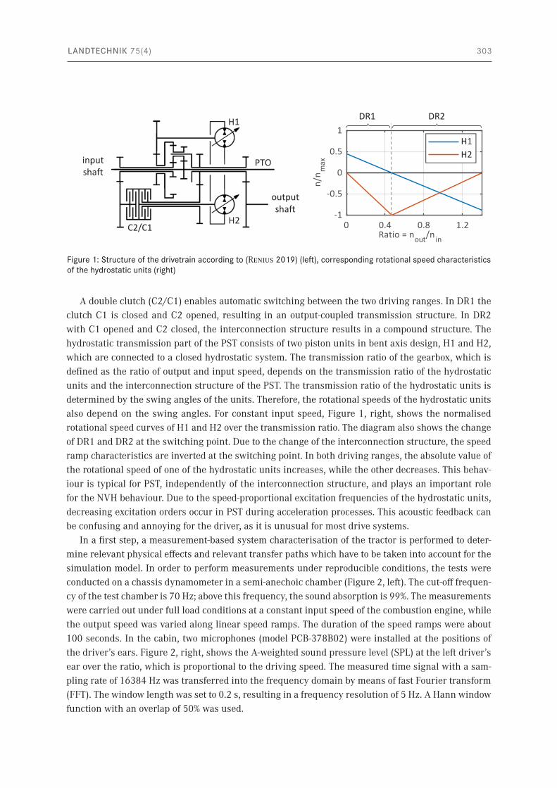
System characterisationThe modelling method is developed and validated for a given standard tractor of medium power class with a hydrostatic-mechanical PST. The PST consists of two driving ranges (DR1, DR2) which differ in the internal connection structure. The structure of the PST is shown in Figure 1, left.
LANDTECHNIK 75(4) 303
A double clutch (C2/C1) enables automatic switching between the two driving ranges. In DR1 the clutch C1 is closed and C2 opened, resulting in an output-coupled transmission structure. In DR2 with C1 opened and C2 closed, the interconnection structure results in a compound structure. The hydrostatic transmission part of the PST consists of two piston units in bent axis design, H1 and H2, which are connected to a closed hydrostatic system. The transmission ratio of the gearbox, which is defined as the ratio of output and input speed, depends on the transmission ratio of the hydrostatic units and the interconnection structure of the PST. The transmission ratio of the hydrostatic units is determined by the swing angles of the units. Therefore, the rotational speeds of the hydrostatic units also depend on the swing angles. For constant input speed, Figure 1, right, shows the normalised rotational speed curves of H1 and H2 over the transmission ratio. The diagram also shows the change of DR1 and DR2 at the switching point. Due to the change of the interconnection structure, the speed ramp characteristics are inverted at the switching point. In both driving ranges, the absolute value of the rotational speed of one of the hydrostatic units increases, while the other decreases. This behav-iour is typical for PST, independently of the interconnection structure, and plays an important role for the NVH behaviour. Due to the speed-proportional excitation frequencies of the hydrostatic units, decreasing excitation orders occur in PST during acceleration processes. This acoustic feedback can be confusing and annoying for the driver, as it is unusual for most drive systems.
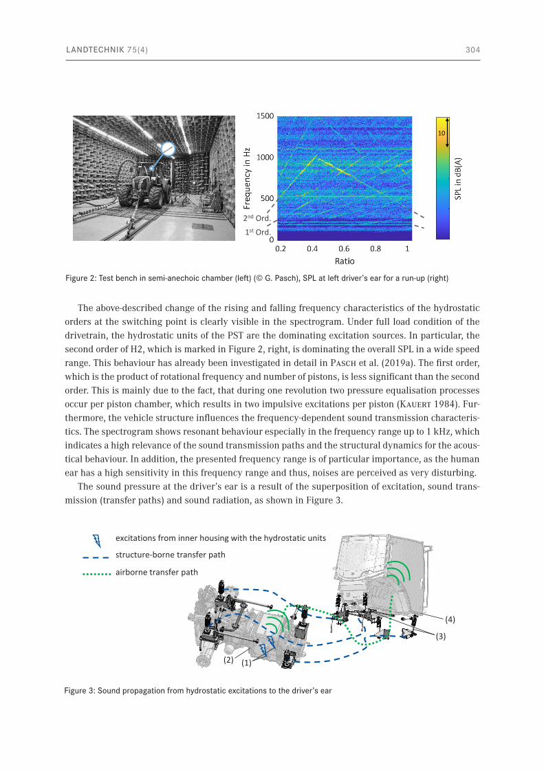
In a first step, a measurement-based system characterisation of the tractor is performed to deter-mine relevant physical effects and relevant transfer paths which have to be taken into account for the simulation model. In order to perform measurements under reproducible conditions, the tests were conducted on a chassis dynamometer in a semi-anechoic chamber (Figure 2, left). The cut-off frequen-cy of the test chamber is 70 Hz; above this frequency, the sound absorption is 99%. The measurements were carried out under full load conditions at a constant input speed of the combustion engine, while the output speed was varied along linear speed ramps. The duration of the speed ramps were about 100 seconds. In the cabin, two microphones (model PCB-378B02) were installed at the positions of the driver’s ears. Figure 2, right, shows the A-weighted sound pressure level (SPL) at the left driver’s ear over the ratio, which is proportional to the driving speed. The measured time signal with a sam-pling rate of 16384 Hz was transferred into the frequency domain by means of fast Fourier transform (FFT). The window length was set to 0.2 s, resulting in a frequency resolution of 5 Hz. A Hann window function with an overlap of 50% was used.
Figure 1: Structure of the drivetrain according to (Renius 2019) (left), corresponding rotational speed characteristics of the hydrostatic units (right)
H1
H2
PTO
C2/C1
outputshaft
inputshaft
DR2 DR1
LANDTECHNIK 75(4) 304
The above-described change of the rising and falling frequency characteristics of the hydrostatic orders at the switching point is clearly visible in the spectrogram. Under full load condition of the drivetrain, the hydrostatic units of the PST are the dominating excitation sources. In particular, the second order of H2, which is marked in Figure 2, right, is dominating the overall SPL in a wide speed range. This behaviour has already been investigated in detail in Pasch et al. (2019a). The first order, which is the product of rotational frequency and number of pistons, is less significant than the second order. This is mainly due to the fact, that during one revolution two pressure equalisation processes occur per piston chamber, which results in two impulsive excitations per piston (Kauert 1984). Fur-thermore, the vehicle structure influences the frequency-dependent sound transmission characteris-tics. The spectrogram shows resonant behaviour especially in the frequency range up to 1 kHz, which indicates a high relevance of the sound transmission paths and the structural dynamics for the acous-tical behaviour. In addition, the presented frequency range is of particular importance, as the human ear has a high sensitivity in this frequency range and thus, noises are perceived as very disturbing.
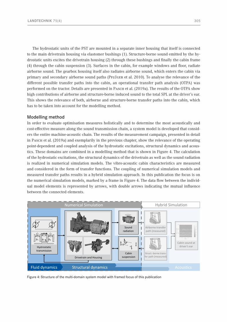
The sound pressure at the driver’s ear is a result of the superposition of excitation, sound trans-mission (transfer paths) and sound radiation, as shown in Figure 3.
Figure 2: Test bench in semi-anechoic chamber (left) (© G. Pasch), SPL at left driver’s ear for a run-up (right)
2nd Ord.
1st Ord.
10
Figure 3: Sound propagation from hydrostatic excitations to the driver’s ear
airborne transfer path
structure-borne transfer path
excitations from inner housing with the hydrostatic units
(1)(2)
(4)
(3)
LANDTECHNIK 75(4) 305
The hydrostatic units of the PST are mounted in a separate inner housing that itself is connected to the main drivetrain housing via elastomer bushings (1). Structure-borne sound emitted by the hy-drostatic units excites the drivetrain housing (2) through these bushings and finally the cabin frame (4) through the cabin suspension (3). Surfaces in the cabin, for example windows and floor, radiate airborne sound. The gearbox housing itself also radiates airborne sound, which enters the cabin via primary and secondary airborne sound paths (Pflüger et al. 2010). To analyse the relevance of the different possible transfer paths into the cabin, an operational transfer path analysis (OTPA) was performed on the tractor. Details are presented in Pasch et al. (2019a). The results of the OTPA show high contributions of airborne and structure-borne induced sound to the total SPL at the driver’s ear. This shows the relevance of both, airborne and structure-borne transfer paths into the cabin, which has to be taken into account for the modelling method.
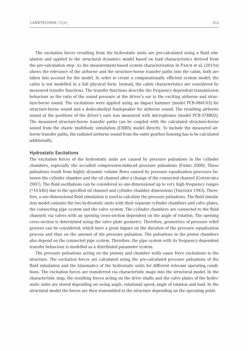
Modelling methodIn order to evaluate optimisation measures holistically and to determine the most acoustically and cost-effective measure along the sound transmission chain, a system model is developed that consid-ers the entire machine-acoustic chain. The results of the measurement campaign, presented in detail in Pasch et al. (2019a) and exemplarily in the previous chapter, show the relevance of the operating point-dependent and coupled analysis of the hydrostatic excitations, structural dynamics and acous-tics. These domains are combined in a modelling method that is shown in Figure 4. The calculation of the hydrostatic excitations, the structural dynamics of the drivetrain as well as the sound radiation is realized in numerical simulation models. The vibro-acoustic cabin characteristics are measured and considered in the form of transfer functions. The coupling of numerical simulation models and measured transfer paths results in a hybrid simulation approach. In this publication the focus is on the numerical simulation models, marked by a frame in Figure 4. The data flow between the individ-ual model elements is represented by arrows, with double arrows indicating the mutual influence between the connected elements.
Figure 4: Structure of the multi-domain system model with framed focus of this publication
Hybrid SimulationNumerical Simulation
Airborne transferpath (measured)
Acoustics
Sound radiation
Struct.-borne trans-fer path (measured)
CabinsuspensionDrivetrain and Housing
Structural dynamics
Hystrostatictransmission
Fluid dynamics
Cabin sound at driver‘s ear
p2p1 p1
LANDTECHNIK 75(4) 306
The excitation forces resulting from the hydrostatic units are pre-calculated using a fluid sim-ulation and applied to the structural dynamics model based on load characteristics derived from the pre-calculation step. As the measurement-based system characterisation in Pasch et al. (2019a) shows the relevance of the airborne and the structure-borne transfer paths into the cabin, both are taken into account for the model. In order to create a computationally efficient system model, the cabin is not modelled in a full physical form. Instead, the cabin characteristics are considered by measured transfer functions. The transfer functions describe the frequency-dependent transmission behaviour as the ratio of the sound pressure at the driver’s ear to the exciting airborne and struc-ture-borne sound. The excitations were applied using an impact hammer (model PCB-086C03) for structure-borne sound and a dodecahedral loudspeaker for airborne sound. The resulting airborne sound at the positions of the driver’s ears was measured with microphones (model PCB-378B02). The measured structure-borne transfer paths can be coupled with the calculated structure-borne sound from the elastic multibody simulation (EMBS) model directly. To include the measured air-borne transfer paths, the radiated airborne sound from the outer gearbox housing has to be calculated additionally.
Hydrostatic ExcitationsThe excitation forces of the hydrostatic units are caused by pressure pulsations in the cylinder chambers, especially the so-called compression-induced pressure pulsations (Fiebig 2000). These pulsations result from highly dynamic volume flows caused by pressure equalisation processes be-tween the cylinder chamber and the oil channel after a change of the connected channel (Goenechea 2007). The fluid oscillations can be considered as one-dimensional up to very high frequency ranges (>10 kHz) due to the specified oil channel and cylinder chamber dimensions (Theissen 1983). There-fore, a one-dimensional fluid simulation is used to calculate the pressure pulsations. The fluid simula-tion model contains the two hydrostatic units with their separate cylinder chambers and valve plates, the connecting pipe system and the valve system. The cylinder chambers are connected to the fluid channels via valves with an opening cross-section dependent on the angle of rotation. The opening cross-section is determined using the valve plate geometry. Therefore, geometries of pressure relief grooves can be considered, which have a great impact on the duration of the pressure equalisation process and thus on the amount of the pressure pulsation. The pulsations in the piston chambers also depend on the connected pipe system. Therefore, the pipe system with its frequency-dependent transfer behaviour is modelled as a distributed parameter system.
The pressure pulsations acting on the pistons and chamber walls cause force excitations to the structure. The excitation forces are calculated using the pre-calculated pressure pulsations of the fluid simulation and the kinematics of the hydrostatic units for different relevant operating condi-tions. The excitation forces are transferred via characteristic maps into the structural model. In the characteristic map, the resulting forces acting on the drive shafts and the valve plates of the hydro-static units are stored depending on swing angle, rotational speed, angle of rotation and load. In the structural model the forces are then transmitted to the structure depending on the operating point.
LANDTECHNIK 75(4) 307
Structural dynamicsThe structural dynamic behaviour is described in an EMBS model. The EMBS enables efficient cal-culation of the structural dynamics of large, flexible structures considering non-linear transmission elements and transient excitations under variable operating conditions in frequency as well as in time domain.
Linear-elastic structural elements such as housing components are modelled as flexible bodies. For this purpose, the individual components are first modelled using the finite element method (FEM) and combined into assemblies. Screw connections are modelled according to (Neher 2012) taking the screw preload into account. Connection and force application points such as bearing points are defined in the FE as interface degree of freedoms (interface DOFs). The FE models are modally re-duced using the substructuring approach according to (Craig and Bampton 1968). The previously defined interface DOFs are retained. The dynamic and quasi-static behaviour of the reduced structure between interface DOFs is considered via eigenmodes and residual modes. The number of eigen-modes considered depends on the selected frequency range. According to (Young and Haile 2000), at least modes of 1.5 times the relevant frequency range should be taken into account. The simulated response signal of an interface DOF includes the rigid body movement, quasi-static deformation, and also the dynamic behaviour up to a frequency range specified by the user. In the modal reduction, all nodal DOFs of the FE system except the interface DOFs are transformed from the nodal space into the modal space. In nodal space, the deformation of a structure is described using displacements at nodes. In the modal space, the deformation is described by a weighted superposition of modes. With the help of the transformation matrix, also known as recovery matrix, which describes the relation-ship between nodal and modal DOFs, the nodal displacements can be calculated from the modal description. This also applies analogously to accelerations and velocities which will be used for the calculation of the sound radiation.
In the EMBS model, non-linear coupling elements between the linear elastic components and as-semblies, such as rolling bearings or elastomer elements, are described in force elements using either linearised or non-linear relationships. Rolling bearings are modelled using a force element which calculates the non-linear stiffness taking the number of rolling elements and Hertzian pressure at the contact points into account. Elastomer bushings are characterised using force-controlled shaker measurements under preload conditions. The force signals were applied in the form of sinus sweeps of different amplitudes and the accelerations on the active and passive side were measured. The stiff-ness and damping values of the linearised force elements are updated with the measurement results.
AcousticsAs the measurement results in Pasch et al. (2019a) show, the directly radiated airborne sound from the drivetrain housing plays a major role. Sound radiation describes the conversion of structure-borne sound into airborne sound. The influence of airborne sound on structure-borne sound is very small due to large impedance differences and can be neglected. The calculation of structure-borne and airborne sound can therefore be carried out in succession. As described above, the velocities on the housing surfaces can be calculated in a high spatial resolution using the transformation matrix. The time-dependent surface velocities of each node are then used as an input for the calculation of the sound radiation and airborne sound at specific receiver points.
LANDTECHNIK 75(4) 308
The FEM and the Boundary Elements Method (BEM) are established methods for the calculation of airborne sound. Both methods are suitable for the investigation of problems in which the physical be-haviour of the acoustic medium can be described using the Helmholtz equation, see (Estorff 2008). For the airborne sound calculation at a specific receiver point, at least the volume of the air space that includes the receiver points has to be modelled using FEM. In comparison, if using BEM, only the sound-emitting structure surface is modelled. Therefore, the modelling effort and the dimension of the system matrix are lower in BEM compared to FEM. The BEM system matrix is asymmetrical and completely filled (Kollmann 2000). In FEM, the system matrix is symmetrical and narrow-band-ed because only neighbouring nodes influence each other (Knothe and Wessels 2017). Thus, for a comparable number of elements, the computational effort in BEM is greater compared to FEM. With regard to the present investigation, the gearbox housing has a large and complex sound radiating sur-face area. In addition, the receiver points of interest are close to the radiating surface. For this investi-gation, a comparable or even less computational effort is expected by using FEM than by using BEM. Another advantage is that the structural housing assemblies are also modelled using FEM. These models can be reused to create the acoustic model, which is a “negative” of the housing structure.
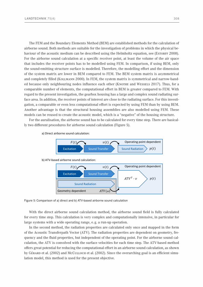
For the auralisation, the airborne sound has to be calculated for every time step. There are basical-ly two different procedures for airborne sound calculation (Figure 5).
With the direct airborne sound calculation method, the airborne sound field is fully calculated for every time step. This calculation is very complex and computationally intensive, in particular for large systems with a wide operating range, e. g. a run-up operation.
In the second method, the radiation properties are calculated only once and mapped in the form of the Acoustic Transferpath Vector (ATV). The radiation properties are dependent on geometry, fre-quency and the fluid properties, but independent of the operating point. For the airborne sound cal-culation, the ATV is convolved with the surface velocities for each time step. The ATV-based method offers great potential for reducing the computational effort in an airborne sound calculation, as shown by Gérard et al. (2002) and McCulloch et al. (2002). Since the overarching goal is an efficient simu-lation model, this method is used for the present objective.
Figure 5: Comparison of a) direct and b) ATV-based airborne sound calculation
Sound RadiationSound TransferExcitation
a) Direct airborne sound calculation:
b) ATV-based airborne sound calculation:
Sound TransferExcitation
Sound Radiation
𝐴𝑇𝑉(𝜔)
𝐹(𝑡) 𝑣(𝑡)
Geometry dependent
Operating point dependent
Operating point dependent
𝑝(𝑡)𝐴𝑇𝑉𝑇 � 𝑣
𝐹(𝑡) 𝑣(𝑡)
𝑝(𝑡)
LANDTECHNIK 75(4) 309
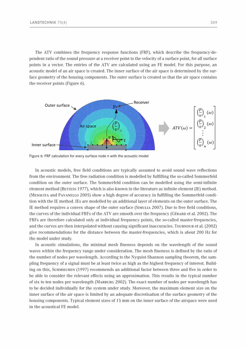
The ATV combines the frequency response functions (FRF), which describe the frequency-de-pendent ratio of the sound pressure at a receiver point to the velocity of a surface point, for all surface points in a vector. The entries of the ATV are calculated using an FE model. For this purpose, an acoustic model of an air space is created. The inner surface of the air space is determined by the sur-face geometry of the housing components. The outer surface is created so that the air space contains the receiver points (Figure 6).
In acoustic models, free field conditions are typically assumed to avoid sound wave reflections from the environment. The free radiation condition is modelled by fulfilling the so-called Sommerfeld condition on the outer surface. The Sommerfeld condition can be modelled using the semi-infinite element method (Bettess 1977), which is also known in the literature as infinite element (IE) method. (Mesquita and Pavanello 2005) show a high degree of accuracy in fulfilling the Sommerfeld condi-tion with the IE method. IEs are modelled by an additional layer of elements on the outer surface. The IE method requires a convex shape of the outer surface (Simulia 2007). Due to free field conditions, the curves of the individual FRFs of the ATV are smooth over the frequency (Gérard et al. 2002). The FRFs are therefore calculated only at individual frequency points, the so-called master-frequencies, and the curves are then interpolated without causing significant inaccuracies. Tournour et al. (2002) give recommendations for the distance between the master-frequencies, which is about 200 Hz for the model under study.
In acoustic simulations, the minimal mesh fineness depends on the wavelength of the sound waves within the frequency range under consideration. The mesh fineness is defined by the ratio of the number of nodes per wavelength. According to the Nyquist-Shannon sampling theorem, the sam-pling frequency of a signal must be at least twice as high as the highest frequency of interest. Build-ing on this, Schmiechen (1997) recommends an additional factor between three and five in order to be able to consider the relevant effects using an approximation. This results in the typical number of six to ten nodes per wavelength (Marburg 2002). The exact number of nodes per wavelength has to be decided individually for the system under study. Moreover, the maximum element size on the inner surface of the air space is limited by an adequate discretisation of the surface geometry of the housing components. Typical element sizes of 15 mm on the inner surface of the airspace were used in the acoustical FE model.
Figure 6: FRF calculation for every surface node n with the acoustic model
𝐴𝑇𝑉 𝜔 =
𝑝𝑣 1
(𝜔)
𝑝𝑣 2
(𝜔)
𝑝𝑣 𝑛
(𝜔)
𝑝
𝑣 𝑡
𝑝𝑣 𝑛
Air space
Inner surface
Outer surface
𝑛1 2
Receiver
LANDTECHNIK 75(4) 310
Since the FE mesh of the acoustic model typically has a lower resolution on the inner surface than the FE mesh of the structural model with a typical mesh size of about 5 mm, the node positions of both models are rarely at the same positions. In order to calculate the surface velocities at exactly the same positions of the acoustic model, the positions of the surface nodes are imported from the acoustic model into the structural dynamics model. These nodes are then connected to the surface of the structural model via tie constraints and considered for creating the transformation matrix.
To enable the conversion of mechanical quantities – structure-borne sound – into acoustic quan-tities – airborne sound – a 2D layer of structural elements is connected to the inner surface of the acoustic model and a fluid-structure interaction is implemented in between. To determine an FRF, one node of the structural elements is deflected using a unit velocity excitation while all other surface points are fixated. The resulting sound pressure at the receiver is calculated and combined with the velocity excitation by amplitude and phase to calculate the complex-valued ratio. This process is per-formed successively for all nodes in all three spatial directions. Due to the large number of nodes and frequency support points, this process is automated.
The calculated ATV can subsequently be applied to all operating points. The sound pressure at a receiver point is calculated by convolution of the ATV with the surface velocities from the EMBS mod-el. The sound contributions of every surface nodes are summed up taking into account the amplitude and phase and thus form the total airborne sound at the receiver.
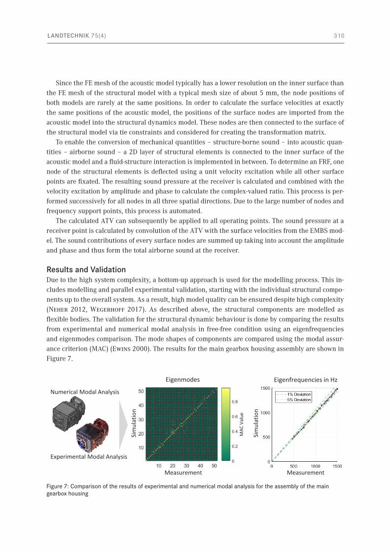
Results and ValidationDue to the high system complexity, a bottom-up approach is used for the modelling process. This in-cludes modelling and parallel experimental validation, starting with the individual structural compo-nents up to the overall system. As a result, high model quality can be ensured despite high complexity (Neher 2012, Wegerhoff 2017). As described above, the structural components are modelled as flexible bodies. The validation for the structural dynamic behaviour is done by comparing the results from experimental and numerical modal analysis in free-free condition using an eigenfrequencies and eigenmodes comparison. The mode shapes of components are compared using the modal assur-ance criterion (MAC) (Ewins 2000). The results for the main gearbox housing assembly are shown in Figure 7.
Figure 7: Comparison of the results of experimental and numerical modal analysis for the assembly of the main gearbox housing
Experimental Modal Analysis
Numerical Modal Analysis
Measurement
Sim
ulat
ion
MAC
Val
ue
Sim
ulat
ion
Measurement
Eigenmodes Eigenfrequencies in Hz
LANDTECHNIK 75(4) 311
In the frequency range up to 1500 Hz, the gearbox housing shows about 50 eigenmodes. The MAC matrix shows high values on the main diagonal and low on the secondary diagonals, indicating a high degree of conformity of the mode shapes between measurement and simulation. The maximum deviation of the eigenfrequencies is less than 5%, which also shows a high correlation.
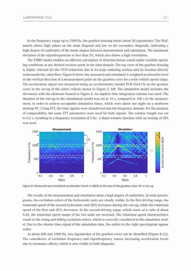
The EMBS model enables an efficient calculation of structure-borne sound under variable operat-ing conditions at any desired receiver point in the time domain. The top cover of the gearbox housing is highly relevant for the NVH behaviour due to its large radiating surface and its location directly underneath the cabin floor. Figure 8 shows the measured and simulated A-weighted acceleration level in the vertical direction of a measurement point on the gearbox cover for a wide vehicle speed range. The acceleration signal was measured using an accelerometer (model PCB-356A15) on the gearbox cover in the set-up of the entire vehicle shown in Figure 2, left. The simulation model includes the drivetrain with the elements framed in Figure 4. An implicit time integration scheme was used. The duration of the run-up in the simulations model was set to 10 s, compared to 100 s in the measure-ment, in order to achieve acceptable simulation times, which were about one night on a multicore desktop PC. Using FFT, the time signals were transferred into the frequency domain. For the purpose of comparability, the same FFT parameters were used for both signals. The window length was set to 0.2 s, resulting in a frequency resolution of 5 Hz. A Hann window function with an overlap of 50% was used.
The results of the measurement and simulation show a high degree of conformity. In both spectro-grams, the excitation orders of the hydrostatic units are clearly visible. In the first driving range, the rotational speed of the second hydrostatic unit (H2) increases during the run-up, while the rotational speed of the first unit (H1) decreases. In the second driving range, which starts at a ratio of about 0.45, the rotational speed ramps of the two units are reversed. The rotational speed characteristics result in the rising and falling excitation orders, which is correctly considered in the simulation mod-el. Due to the shorter time signal of the simulation data, the orders in the right spectrogram appear wider.
At about 600 and 1000 Hz, two eigenmodes of the gearbox cover can be identified (Figure 8 (1)). The coincidence of excitation frequency and eigenfrequency causes increasing acceleration levels due to resonance effects, which is also visible in both diagrams.
Figure 8: Measured and simulated acceleration levels in dB(A) at the top of the gearbox cover for a run-up
10
(1)
(2)
(1)
LANDTECHNIK 75(4) 312
In the measurement signal, further excitation orders can be identified. Excitations at frequencies that are proportional to the output speed are due to gear mesh excitation. Excitations at constant frequencies, e. g. at about 1070 and 1400 Hz (Figure 8 (2)), are caused by auxiliary units such as fur-ther hydrostatic pumps. These excitation sources are not the dominant sources of the drivetrain and therefore not considered in the simulation model.
Nevertheless, the spectrograms show small deviations in the quantitative acceleration levels be-tween measurement and simulation. A reason for these deviations could be the neglected additional damping effects in the simulation model. The model considers the effects of modal damping and damping in coupling elements like bearings and bushings. For example, damping effects caused by oil inside the gearbox housing have been neglected. Therefore, the modelling of damping effects with higher accuracy is an improvement potential for the method.
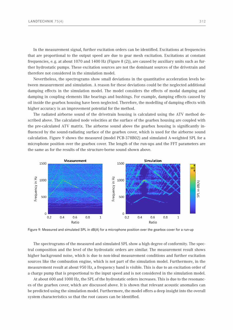
The radiated airborne sound of the drivetrain housing is calculated using the ATV method de-scribed above. The calculated node velocities at the surface of the gearbox housing are coupled with the pre-calculated ATV matrix. The airborne sound above the gearbox housing is significantly in-fluenced by the sound-radiating surface of the gearbox cover, which is used for the airborne sound calculation. Figure 9 shows the measured (model PCB-378B02) and simulated A-weighted SPL for a microphone position over the gearbox cover. The length of the run-ups and the FFT parameters are the same as for the results of the structure-borne sound shown above.
The spectrograms of the measured and simulated SPL show a high degree of conformity. The spec-tral composition and the level of the hydrostatic orders are similar. The measurement result shows higher background noise, which is due to non-ideal measurement conditions and further excitation sources like the combustion engine, which is not part of the simulation model. Furthermore, in the measurement result at about 950 Hz, a frequency band is visible. This is due to an excitation order of a charge pump that is proportional to the input speed and is not considered in the simulation model.
At about 600 and 1000 Hz, the SPL of the hydrostatic orders increases. This is due to the resonanc-es of the gearbox cover, which are discussed above. It is shown that relevant acoustic anomalies can be predicted using the simulation model. Furthermore, the model offers a deep insight into the overall system characteristics so that the root causes can be identified.
Figure 9: Measured and simulated SPL in dB(A) for a microphone position over the gearbox cover for a run-up
10
LANDTECHNIK 75(4) 313
Overall, the validations of the structural behaviour, the structure-borne sound and the airborne sound show a high degree of conformity. The simulation model was created from geometry and ma-terial parameters and under consideration of the operation strategy of the drivetrain. Only the modal damping of the structural components, as well as the stiffness and damping properties of the elas-tomer bushings, were measured. The presented simulation approach including the determination of the bushing characteristics is applicable in a forward development process. Therefore, the modelling method allows identifying and optimising acoustic anomalies in the NVH behaviour even before pro-totypes and measurements at a system level are available.
ConclusionsThis paper presents a methodology for a holistic examination of the NVH behaviour for tractors with the focus on the excitations caused by the hydrostatic transmission part of PST. A measurement-based system characterisation serves as the basis for the construction of a model chain which covers the relevant system elements. The individual domains for calculation of excitation forces, structural dy-namics and acoustics were explained and simulation results were compared with measurement re-sults. The comparisons of structure-borne and airborne sound between measurement and simulation results show a high degree of conformity. The method allows identifying and reducing acoustic anom-alies in earlier phases of the product development process prior to the prototyping stage.
Further studies need to primarily consider the vibro-acoustic behaviour of the cabin in order to cal-culate the airborne sound at the driver’s ear. The cabin was therefore characterised by measurements in the form of FRFs. In a next step, the determined FRFs are to be convolved with the calculated struc-ture-borne and airborne sound from the simulation. The validity of the method is to be assessed. Fur-thermore, a target-oriented analysis and optimisation method for system models are to be developed.
ReferencesBettess, P. (1977): Infinite elements. International Journal for Numerical Methods in Engineering 11(1), pp. 53–64,
https://doi.org/10.1002/nme.1620110107
Craig, R.R.[J.]; Bampton, M.C.C. (1968): Coupling of substructures for dynamic analyses. AIAA Journal 6(7), pp. 1313–1319, https://doi.org/10.2514/3.4741
Drichel, P.; Jaeger, M.; Müller-Giebeler, M. (2019): Mit elektrischem Antrieb und modellbasierter Systemanalyse nahezu lautlos in die Zukunft. ATZextra 24(S5), S. 52–57, https://doi.org/10.1007/s35778-019-0050-2
Estorff, O. von (2008): Challenges in Technical Acoustics: What Can Be Computed Today. 7. LS-DYNA Anwenderforum, Bamberg 2008 https://www.dynamore.de/de/download/papers/forum08/dokumente/A-I-02.pdf, accessed on 5 June 2020
Ewins, D.J. (2000): Modal Testing. Theory, Practice and Application. Baldock, Research Studies Press
Fiebig, W. (2000): Schwingungs- und Geräuschverhalten der Verdrängerpumpen und hydraulischen Systeme. Vorgehensweise, Maßnahmen und Potential zur Geräuschminderung. Dissertation, Universität Tübingen
Gérard, F.; Tournour, M.; El Masri, N.; Cremers, L.; Felice, M.; Selmane, A. (2002): Acoustic transfer vectors for numerical modeling of engine noise. Journal of Sound and Vibration 36(7), pp. 20–25
Goenechea, E. (2007): Mechatronische Systeme zur Pulsationsminderung hydrostatischer Verdrängereinheiten. Dissertation, RWTH Aachen
Jaeger, M.; Drichel, P.; Müller-Giebeler, M.; Hameyer, K.; Jacobs, G.; Vorländer, M. (2019): Erweiterung NVH Simulati-onsmodell. Erweiterung der Simulationsmöglichkeiten für maschinenakustische Untersuchungen an E-Motive-An-trieben im Kontext zur Fahrzeugstruktur. FVA (Heft Nr. 1730), Forschungsvereinigung Antriebstechnik e.V.
LANDTECHNIK 75(4) 314
Jochum, S.; Lange, S.; Wolff, K. (2013): Akustikoptimierung Eines Hydromechanischen Getriebes. ATZoffhighway 6(1), S. 72–79, https://doi.org/10.1365/s35746-013-0072-4
Kauert, P. (1984): Hydraulikpumpen, -motoren und -aggregate. In: Taschenbuch Akustik. Teil 1: Physikalische Grundlagen, Schalleinwirkung auf den Menschen, Lärmschutzforderungen, Messtechnik, Maschinenakustik. Hg. Fasold, W.; Kraak, W.; Schirmer, W., Berlin, VEB Verlag Technik
Knothe, K.; Wessels, H. (2017): Finite Elemente. Eine Einführung für Ingenieure. Berlin, Springer Verlag
Kollmann, F.G. (2000): Maschinenakustik. Grundlagen, Meßtechnik, Berechnung, Beeinflussung. Berlin, Heidelberg, Springer Verlag
Krüger, J.; Meyer, H.J. (2015): Fahrdynamik – Fahrsicherheit – Fahrerplatz. In: Jahrbuch Agrartechnik 2014, Hg. Frerichs, L., Braunschweig, Institut für mobile Maschinen und Nutzfahrzeug, S. 1–10
Marburg, S. (2002): Six boundary elements per wavelength: Is that enough? Journal of Computational Acoustics 10(01), pp. 25–51, https://doi.org/10.1142/S0218396X02001401
McCulloch, C.; Tournour, M.; Guisset, P. (2002): Modal Acoustic Transfer Vectors Make Acoustic Radiation Models Practical for Engines and Rotating Machinery https://support.ansys.com/staticassets/ANSYS/staticassets/resourcelibrary/confpaper/2002-Int-ANSYS-Conf-209.pdf, accessed on 5 June 2020
Mesquita, E.; Pavanello, R. (2005): Numerical methods for the dynamics of unbounded domains. Journal of Computational and Applied Mathematics 24(1), https://doi.org/10.1590/S0101-82052005000100001
Müller-Giebeler, M.; Drichel, P.; Jäger, M.; Klein, J.; Wegerhoff, M.; Rick, S.; Vorländer, M.; Jacobs, G.; Hameyer, K. (2017): Comprehensive model for the assessment of the NVH-behavior of electric vehicles. In: Aachen Acoustics Colloquium 2017, 27–29 Oct 2017, Aachen, pp. 75–88
Neher, J. (2012): Rechnerische und experimentelle Untersuchungen der Schallabstrahlung bei Fahrzeuggetrieben. Dissertation, Technische Universität Ilmenau
Pasch, G.; Jacobs, G.; Höpfner, G.; Berroth, J.K. (2019a): Methodik zur modellbasierten NVH-Analyse von Traktoren mit hydrostatisch-mechanischen Leistungsverzweigungsgetrieben. In: Antriebstechnisches Kolloquium ATK 2019, Institut für Maschinenelemente und Systementwicklung der RWTH Aachen, 12.–13.03.2019, Aachen, Books on Demand, S. 309–328.
Pasch, G.; Jacobs, G.; Höpfner, G.; Berroth, J.K. (2019b): Multi-Domain Simulation for the Assessment of the NVH Behaviour of a Tractor with Hydrostatic-Mechanical Power Split Transmission. In: Land. Technik AgEng 2019, Hannover, 8–9 Nov 2019, Düsseldorf, VDI Verlag GmbH (VDI-Berichte 2361), pp. 19–27
Pflüger, M.; Brandl, F.; Bernhard, U.; Feitzelmayer, K. (2010): Fahrzeugakustik. Wien, Springer Verlag
Renius, K.T. (2003): Hydrostatische Fahrantriebe für mobile Arbeitsmaschinen. In: Antriebssysteme für Off-Road-Einsätze. Tagung Garching, 18. und 19. September 2003, VDI-Berichte 1793, Düsseldorf, VDI-Verlag, S. 65–78
Renius, K.T. (2019): Fundamentals of Tractor Design. Cham, Springer Verlag
Rick, S.; Klein, J.; Wegerhoff, M.; Hameyer, K.; Vorländer, M.; Jacobs, G. (2015): E-MOTIVE NVH-Simulationsmodell. Modellbildung zur NVH Simulation eines E-MOTIVE Antriebsstrangs. FVA Heft 1130, Forschungsvereinigung Antriebstechnik e.V.
Schmiechen, P. (1997): Travelling wave speed coincidence. Dissertation, Imperial College of Science, Technology and Medicine, University of London
Siemens (2018): Schall- und Schwingungsphänomene ermitteln durch Simulation und Versuch. https://www.plm.automation.siemens.com/country/de-de/topic/seminar-schallmessung/29816, accessed on 20 May 2020
Simulia (2007): Sound Radiation Analysis of Automobile Engine Covers. Abaqus Technology Brief. https://www.ssanalysis.co.uk/hubfs/KB_Technical_Briefs/Acoustic_Engine_Cover.pdf, accessed on 5 June 2020
Theissen, H. (1984): Die Berücksichtigung instationärer Rohrströmung bei der Simulation hydraulischer Anlagen. Dissertation, Technische Hochschule Aachen
LANDTECHNIK 75(4) 315
Tournour, M.; Dessart, S.; McCulloch, C. (2002): On the accuracy of vibro-acoustic solutions using the ATV method. In: P. Sas und B. van Hal (Hg.), ISMA 2002, V. International Conference on Noise and Vibration Engineering. Leuven, 16–18 Sept 2002, pp. 2223–2230
Vajna, S.; Weber, C.; Zeman, K.; Hehenberger, P.; Gerhard, D.; Wartzack, S. (2018): CAx für Ingenieure. Berlin, Heidelberg, Springer Verlag
Wegerhoff, M. (2017): Methodik zur numerischen NVH Analyse eines elektrifizierten PKW-Antriebsstrangs. Dissertation, RWTH Aachen
Young, J.T.; Haile, W.B. (2000): Primer on the Craig-Bampton Method. https://femci.gsfc.nasa.gov/craig_bampton/Primer_on_the_Craig-Bampton_Method.pdf, accessed on 5 June 2020
AuthorsGerwin Pasch, M.Sc. is a research assistant and head of the research group “Noise Vibration Harshness” at the Institute for Machine Elements and Systems Engineering (MSE), Dr.-Ing. Joerg Berroth is head of the research division “Systems Engineering – Modelling and Simulation” at the MSE and Univ.-Prof. Dr.-Ing. Georg Jacobs is head of the MSE at RWTH Aachen University, Schinkelstr. 10, 52062 Aachen. E-Mail: [email protected]
AcknowledgementThe authors would like to thank CLAAS Industrietechnik GmbH and especially Dr.-Ing. Marco Ramm for funding and supporting the research project.
NoteThe topic has been presented on 77th Conference LAND.TECHNIK – AgEng 2019, Hannover, 8–9th November 2019 and an abridged version was published in VDI Report No. 2361.