Embed Size (px)
Citation preview
DELIVERABLE #1
PROJECT WHITE PAPER
NVR Strength Criteria
Implementation into
MAESTRO Finite Element
Analysis Application NSRP Ship Design & Material Technologies
Panel Project
(ATI Award No. #2010-388) Cleared Internally under Case No. DS-TCS015
9/30/2011
DRS Defense Solutions, LLC, Advanced Marine Technology Center
i | P a g e
Ship Design & Material Technologies Panel Project:
NVR Strength Criteria Implementation into MAESTRO FEA Application
(Cleared for Public Release)
Table of Contents Introduction .................................................................................................................................................. 1
National Shipbuilding Research Program ................................................................................................. 1
Panel Projects............................................................................................................................................ 1
Panel Project Scope & Team Approach ........................................................................................................ 2
Project Background and Benefits .............................................................................................................. 2
Project Methods and Procedures ............................................................................................................. 3
NVR Background ........................................................................................................................................... 4
Structural Engineering Practices for NVR Classification ............................................................................... 5
General Issue and Background ................................................................................................................. 5
Problems with Acceptance Criteria........................................................................................................... 5
Problems with Processing and Post-processing Acceptance Criteria ....................................................... 5
Solutions ................................................................................................................................................... 5
Technical Approach ....................................................................................................................................... 6
Distribution of the NVR Implementation .................................................................................................. 6
MAESTRO Software System & Open Product Model Architecture ........................................................... 7
The Finite Element Analysis (FEA) Process ............................................................................................... 8
Technical Approach Summary ................................................................................................................ 15
Project Deliverables .................................................................................................................................... 15
Project White Paper ................................................................................................................................ 15
Implementation Manual ......................................................................................................................... 15
Application User Guide and Examples .................................................................................................... 15
Future NSRP Project Topics ......................................................................................................................... 16
References .................................................................................................................................................. 17
DISCLAIMER: The specific implementation of the MAESTRO FEA Application (including incorporation of
NVR Strength criteria) described herein has not been reviewed, tested or endorsed by the U.S. Navy, nor
have the requisite Government verification, validation and accreditation steps been completed that
would enable direct application on any Navy program.
DRS Defense Solutions, LLC, Advanced Marine Technology Center
1 | P a g e
Ship Design & Material Technologies Panel Project:
NVR Strength Criteria Implementation into MAESTRO FEA Application
(Cleared for Public Release)
Introduction
National Shipbuilding Research Program The National Shipbuilding Research Program (NSRP) was created by U.S. shipyards at the Navy’s request
to reduce the cost of building and maintaining U.S. Navy warships. NSRP is a collaboration of several
major U.S. shipyards focused on industry-wide implementation of solutions to common cost drivers. The
program targets solutions to consensus priority issues identified by the Navy shipbuilding community
and industry in undertaking R&D efforts that exhibit a compelling business case to increase warship
affordability by improving U.S. shipbuilding and ship repair efficiency. Solutions include both leverage of
best commercial practices and creation of industry-wide initiatives with aggressive technology transfer
to, and buy-in by, multiple U.S. shipyards.[a]
The mission of NSRP is to manage and focus national shipbuilding and ship repair research and
development funding on technologies that will reduce the cost of ships to the U.S. Navy and other
National Security Customers by leveraging best commercial practices and improving the efficiency of the
U.S. shipbuilding and ship repair industry. Provide a collaborative framework to improve ship-related
technical and business processes. [a]
Panel Projects Within the NSRP, there are 10 panels that correspond to narrow technical and/or process areas while
being aligned to the broader major initiatives of the NSRP Strategic Investment Plan. The Executive
Control Board typically sets aside a modest amount of money each year to fund relatively small (less
than $100k), short-term (12 months or less) projects recommended by the Panel Chairs. This project,
NVR Strength Criteria Implementation into MAESTRO FEA Application, represents one of the Panel
Projects that was awarded in March 2010. Details of the Panel Project and Scope can be found in later
sections of this report.
DRS Defense Solutions, LLC, Advanced Marine Technology Center
2 | P a g e
Ship Design & Material Technologies Panel Project:
NVR Strength Criteria Implementation into MAESTRO FEA Application
(Cleared for Public Release)
Panel Project Scope & Team Approach The objective of this NSRP SDMT Panel project was to implement the Naval Vessel Rules’ (NVR)
structural strength criteria (i.e. NVR Table 7 1-3-4/4.1, Reference [b]) as an integrated structural
evaluation criteria set within the global ship-oriented finite element analysis (FEA) computer program
MAESTRO. Industry and government experts participated in the application of the NVR’s by defining
requirements, exercising, and testing this new technology, and were to identify any additional
developments that would make the structural direct analysis process, in the context of NVR strength
criteria, more efficient.
DRS Defense Solutions, LLC, Advanced Marine Technology Center (DRS AMTC), a division of DRS Training
& Control Systems, LLC was the acting prime contractor. The following organizations participated as
sub-contractors under the direction of DRS AMTC: NSWCCD Code 6510, General Dynamics Bath Iron
Works (GDBIW), Huntington Ingalls Industries (Ingalls), and American Bureau of Shipping Naval
Engineering Department (ABS NED). These participants understood that the development of this new
technology would address an industry need that was currently not being met for classing vessels under
the NVRs.
The goals of this panel project were to address the NVR structural direct analysis requirements of the US
Navy, industry shipyards and ABS by implementing the NVR structural strength criteria in the finite
element analysis computer program MAESTRO and create functionality to better facilitate the
processing/post-processing of the strength criteria results. Achieving these objectives would enable the
US Navy, industry, and ABS to more quickly apply the NVR structural criteria to new ship designs, design
evaluations, as well as for assessing repairs, changes, and through-life condition of naval ships.
Project Background and Benefits Past NSRP projects (e.g., Improved Methods for Generation of Full-Ship Simulation/Analysis Methods and
The Scantling Approval Process [a]) addressed important elements and processes associated with
today’s ship structural design in the context of direct analysis and ABS classification. The panel project
proposed herein was aimed to complement both of these projects. The Improved Methods for
Generation of Full-Ship Simulation/Analysis Methods project focused on creating analysis models while
the project described herein focused on processing/post-processing (specifically the NVR strength
criteria). The panel project proposed herein also complemented the Scantling Approval Process project
by focusing on Naval Ships classed under the NVRs as opposed to those classed under the SVRs. Further,
the identification of needs from both submitter (shipyards) and reviewer (ABS/NSWCCD 6510) of NVR
classed naval ships should assist in improving the efficiencies of scantling approval, which was precisely
the subject the Scantling Approval Process project addressed.
Class requirements regarding direct analysis, specifically strength criteria, in many cases are not
integrated into FEA applications. It becomes the responsibility of the engineering analyst to use internal
organizational processes (e.g., spread sheets and macros) to first extract structural response results (i.e.
deformations/stresses) and to second perform external strength calculations. Finally, the engineering
analyst must post-process these results within the context of the global FEA model, which can also be
difficult, time-consuming and error prone. Recent ship acquisitions exercising this process with the
Naval Vessel Rules, e.g., US Navy’s DDG-1000, could have benefitted from this projects proposed criteria
integration. All future ships requiring NVR classification (e.g., USCG’s Offshore Patrol Cutter) will also
have to complete this process and will therefore benefit from this new technology.
DRS Defense Solutions, LLC, Advanced Marine Technology Center
3 | P a g e
Ship Design & Material Technologies Panel Project:
NVR Strength Criteria Implementation into MAESTRO FEA Application
(Cleared for Public Release)
Further, this project provided an opportunity for industry stakeholders to advance the discussions for
more efficient ship structural design techniques and assessment procedures. The US Navy ship design
and assessment community has long term requirements to improve tools and techniques in this area
that are aimed to better define future ship design performance standards.
Project Methods and Procedures Software development at DRS AMTC follows the agile development process. All modern software
development practices, especially agile development methodologies such as the Unified Process (UP)
and eXtreme Programming, advocate design and implementation protocols that emphasize the need for
iterative cycles of planning, requirements analysis, design, coding, and acceptance testing. The agile
process produces software quickly, and adapts easily to changes in requirements, allowing the customer
to stay involved with the project as the software matures. This software development process was
employed by DRS AMTC to successfully implement the NVR strength criteria and incorporate any
additional user needs identified during the development process.
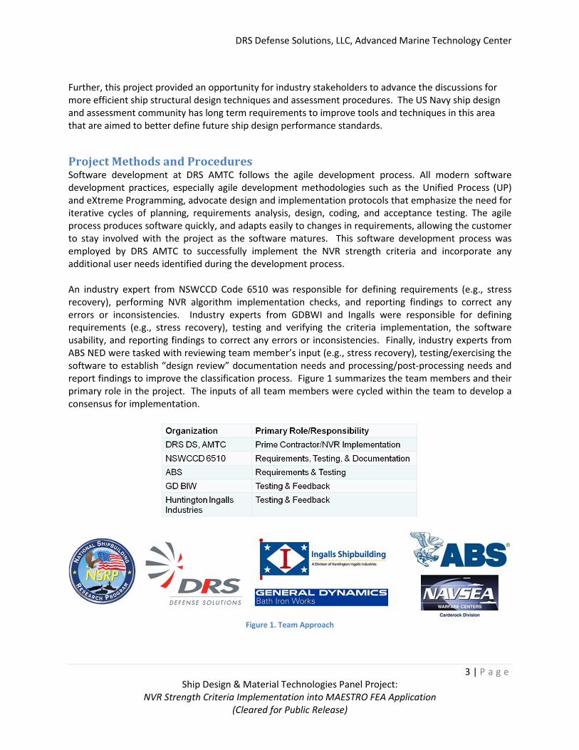
An industry expert from NSWCCD Code 6510 was responsible for defining requirements (e.g., stress
recovery), performing NVR algorithm implementation checks, and reporting findings to correct any
errors or inconsistencies. Industry experts from GDBWI and Ingalls were responsible for defining
requirements (e.g., stress recovery), testing and verifying the criteria implementation, the software
usability, and reporting findings to correct any errors or inconsistencies. Finally, industry experts from
ABS NED were tasked with reviewing team member’s input (e.g., stress recovery), testing/exercising the
software to establish “design review” documentation needs and processing/post-processing needs and
report findings to improve the classification process. Figure 1 summarizes the team members and their
primary role in the project. The inputs of all team members were cycled within the team to develop a
consensus for implementation.
Figure 1. Team Approach
DRS Defense Solutions, LLC, Advanced Marine Technology Center
4 | P a g e
Ship Design & Material Technologies Panel Project:
NVR Strength Criteria Implementation into MAESTRO FEA Application
(Cleared for Public Release)
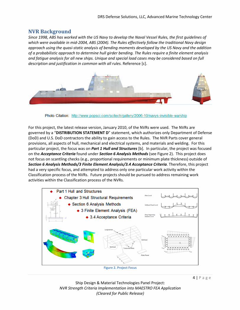
NVR Background Since 1998, ABS has worked with the US Navy to develop the Naval Vessel Rules, the first guidelines of
which were available in mid-2004, ABS (2004). The Rules effectively follow the traditional Navy design
approach using the quasi-static analysis of bending moments developed by the US Navy and the addition
of a probabilistic approach to determine hull girder bending. The Rules require a finite element analysis
and fatigue analysis for all new ships. Unique and special load cases may be considered based on full
description and justification in common with all rules. Reference [c].
For this project, the latest release version, January 2010, of the NVRs were used. The NVRs are
governed by a “DISTRIBUTION STATEMENT D” statement, which authorizes only Department of Defense
(DoD) and U.S. DoD contractors the ability to gain access to the Rules. The NVR Parts cover general
provisions, all aspects of hull, mechanical and electrical systems, and materials and welding. For this
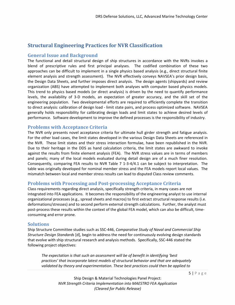
particular project, the focus was on Part 1 Hull and Structures [b]. In particular, the project was focused
on the Acceptance Criteria found under Section 6 Analysis Methods (see Figure 2). This project does
not focus on scantling checks (e.g., proportional requirements or minimum plate thickness) outside of
Section 6 Analysis Methods/3 Finite Element Analysis/3.4 Acceptance Criteria. Therefore, this project
had a very specific focus, and attempted to address only one particular work activity within the
Classification process of the NVRs. Future projects should be pursued to address remaining work
activities within the Classification process of the NVRs.
Figure 2. Project Focus
DRS Defense Solutions, LLC, Advanced Marine Technology Center
5 | P a g e
Ship Design & Material Technologies Panel Project:
NVR Strength Criteria Implementation into MAESTRO FEA Application
(Cleared for Public Release)
Structural Engineering Practices for NVR Classification
General Issue and Background The functional and detail structural design of ship structures in accordance with the NVRs invokes a
blend of prescriptive rules and first principal analyses. The codified combination of these two
approaches can be difficult to implement in a single physics based analysis (e.g., direct structural finite
element analysis and strength assessment). The NVR effectively conveys NAVSEA’s prior design basis,
the Design Data Sheets, and further imposes direct analysis. The design agents (shipyards) and review
organization (ABS) have attempted to implement both analyses with computer based physics models.
This trend to physics based models (or direct analysis) is driven by the need to quantify performance
levels, the availability of 3-D models, an expectation of greater accuracy, and the skill set of the
engineering population. Two developmental efforts are required to efficiently complete the transition
to direct analysis: calibration of design load - limit state pairs, and process optimized software. NAVSEA
generally holds responsibility for calibrating design loads and limit states to achieve desired levels of
performance. Software development to improve the defined processes is the responsibility of industry.
Problems with Acceptance Criteria The NVR only presents novel acceptance criteria for ultimate hull girder strength and fatigue analysis.
For the other load cases, the limit states developed in the various Design Data Sheets are referenced in
the NVR. These limit states and their stress interaction formulae, have been republished in the NVR.
Due to their heritage in the DDS as hand calculation criteria, the limit states are awkward to invoke
against the results from finite element analysis (FEA). The NVR stress values are in terms of members
and panels; many of the local models evaluated during detail design are of a much finer resolution.
Consequently, comparing FEA results to NVR Table 7 1-3-4/4.1 can be subject to interpretation. The
table was originally developed for nominal member stress and the FEA models report local values. The
mismatch between local and member stress results can lead to disputed Class review comments.
Problems with Processing and Post-processing Acceptance Criteria
Class requirements regarding direct analysis, specifically strength criteria, in many cases are not
integrated into FEA applications. It becomes the responsibility of the engineering analyst to use internal
organizational processes (e.g., spread sheets and macros) to first extract structural response results (i.e.
deformations/stresses) and to second perform external strength calculations. Further, the analyst must
post-process these results within the context of the global FEA model, which can also be difficult, time-
consuming and error prone.
Solutions Ship Structure Committee studies such as SSC-446, Comparative Study of Naval and Commercial Ship
Structure Design Standards [d], begin to address the need for continuously evolving design standards
that evolve with ship structural research and analysis methods. Specifically, SSC-446 stated the
following project objectives:
The expectation is that such an assessment will be of benefit in identifying ‘best
practices’ that incorporate latest models of structural behavior and that are adequately
validated by theory and experimentation. These best practices could then be applied to
DRS Defense Solutions, LLC, Advanced Marine Technology Center
6 | P a g e
Ship Design & Material Technologies Panel Project:
NVR Strength Criteria Implementation into MAESTRO FEA Application
(Cleared for Public Release)
new designs and to in-service assessments of existing ships; either on a ship-specific
basis or through the development of new, unified structural design criteria. The project is
intended to address these broader objectives. [d]
Further activity in this area is needed so industry can adequately address the need for more efficient
ship structural design techniques and assessment procedures. The US Navy ship design and assessment
community has long term requirements to improve tools and techniques in this area to better define
future ship design performance standards.
The focus of this project was to address the specific need of US Navy and industry by implementing
current design standards (i.e., for naval vessels) inside of the design and assessment tool MAESTRO. The
notion of the project was to extend MAESTRO’s existing and comprehensive structural strength
assessment analysis paradigm (described in the following sections) to include NVR Criteria.
Technical Approach In the following sections, a description is provided for the reader to understand the basic capability
background of MAESTRO as well as its product model framework architecture. Further, this background
information is intended to provide the reader with an understanding of how the project objective (i.e.,
NVR strength criteria implementation) fit into an existing, and well established, strength assessment
paradigm within MAESTRO. Two key aspects to this MAESTRO strength assessment paradigm, namely
Evaluation Patch creation and Stress Recovery, are expanded upon for a more complete understanding
of the NVR Strength Criteria implementation.
Distribution of the NVR Implementation As stated previously, the NVRs are a “Distribution Statement D” document; therefore, the NVR
documents and the software implementation of the NVRs are governed by the following stipulations:
• The NVR will not be shared with any subcontractors working on this NSRP panel project task who are not verified to be certified U.S. contractors.
• The NVR will not be shared with any foreign elements of DRS unless the necessary export license is approved via the U.S. State Department.
• Only "U.S. Person" (as defined in the ITAR regulations) will be allowed access to the NVR or NVR criteria as part of the execution of this task.
• The MAESTRO article of software (i.e., Dynamic Link Library, NVR DLL file) will not be kept on, or accessed through a web site, or transmitted via unencrypted electronic means.
• The MAESTRO article of software (i.e. Dynamic Link Library, NVR DLL file) will be considered a "Defense Article" in accordance with Sec 120.7 of the ITAR regulations, and access to it will be controlled accordingly.
• DRS AMTC will not make the MAESTRO article of software (i.e. Dynamic Link Library, NVR DLL file) available for commercial sale without obtaining NAVSEA 05D approvals of the individual entities to which sale is proposed. It is understood that such sales will be treated no differently than a determination to release the NVR Rules themselves. If sale to any non-U.S. entities is proposed, an export license must additionally be obtained.
The MAESTRO software does not include any of the NVR materials and will only facilitate the usage of the NVR DLL file. These NVR implementation stipulations provided by NAVSEA, were agreed upon, with specific language to accurately characterize the distribution of the MAESTRO article of software (i.e. Dynamic Link Library, NVR DLL file).
DRS Defense Solutions, LLC, Advanced Marine Technology Center
7 | P a g e
Ship Design & Material Technologies Panel Project:
NVR Strength Criteria Implementation into MAESTRO FEA Application
(Cleared for Public Release)
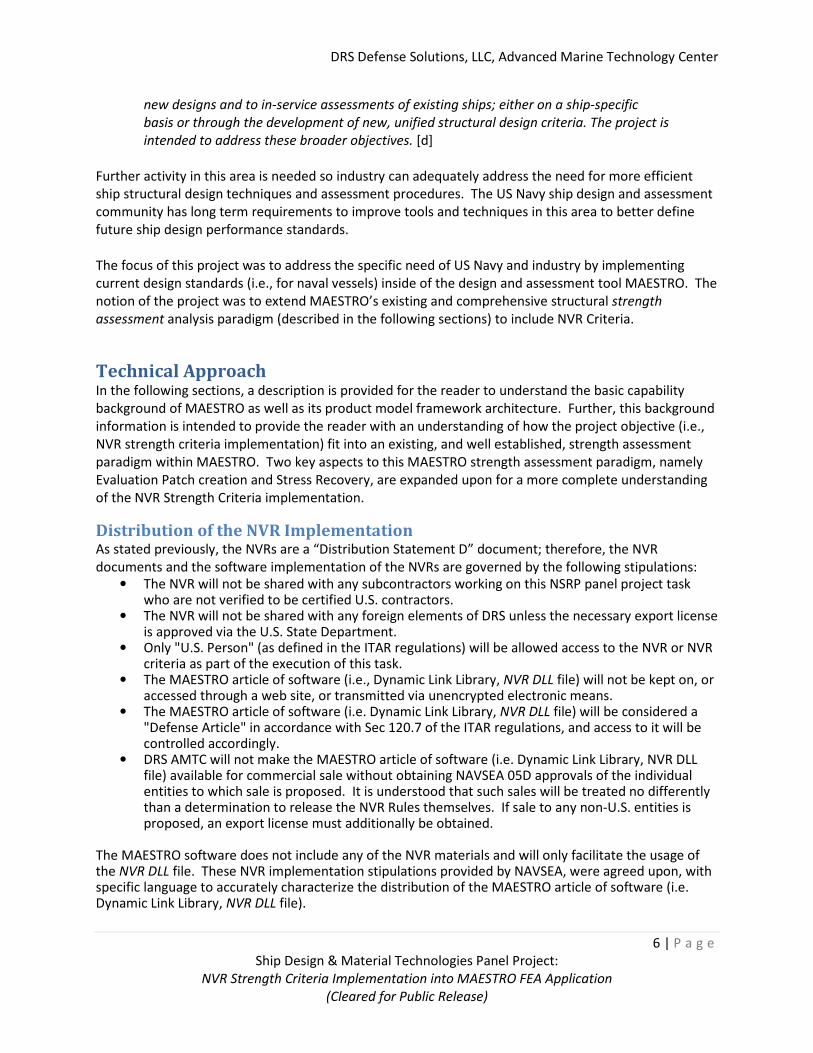
MAESTRO Software System & Open Product Model Architecture MAESTRO (Method for Analysis, Evaluation, and STRuctural Optimization) is a design, analysis, and
evaluation tool specifically tailored for floating structures and has been fielded as a commercial product
for over 20 years and has a world-wide user base. MAESTRO’s history is rooted in rationally-based
structural design, which is defined as a design directly and entirely based on structural theory and
computer-based methods of structural analysis (e.g., finite element analysis). MAESTRO core
components are: rapid coarse-mesh finite element modeling, ship-based loading, finite element
analysis, limit state analysis (e.g., at the hull girder level, stiffened panel level, and local member level),
and design evaluation (Figure 3).
Figure 3. MAESTRO Core Capability
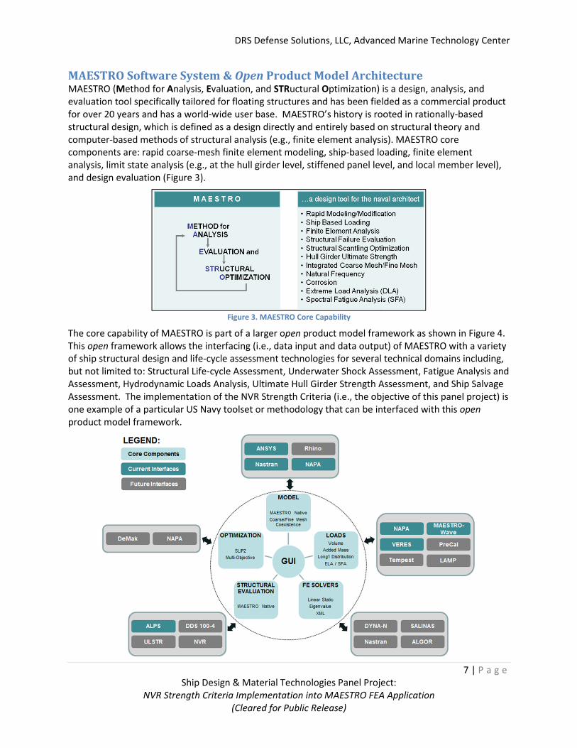
The core capability of MAESTRO is part of a larger open product model framework as shown in Figure 4.
This open framework allows the interfacing (i.e., data input and data output) of MAESTRO with a variety
of ship structural design and life-cycle assessment technologies for several technical domains including,
but not limited to: Structural Life-cycle Assessment, Underwater Shock Assessment, Fatigue Analysis and
Assessment, Hydrodynamic Loads Analysis, Ultimate Hull Girder Strength Assessment, and Ship Salvage
Assessment. The implementation of the NVR Strength Criteria (i.e., the objective of this panel project) is
one example of a particular US Navy toolset or methodology that can be interfaced with this open
product model framework.
DRS Defense Solutions, LLC, Advanced Marine Technology Center
8 | P a g e
Ship Design & Material Technologies Panel Project:
NVR Strength Criteria Implementation into MAESTRO FEA Application
(Cleared for Public Release)
Figure 4. MAESTRO Open Product Model Framework
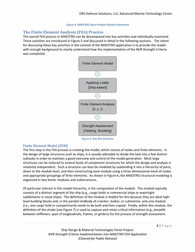
The Finite Element Analysis (FEA) Process The overall FEA process in MAESTRO can be decomposed into key activities and individually examined.
These activities are introduced in Figure 5 and discussed in detail in the following sections. The intent
for discussing these key activities in the context of the MAESTRO application is to provide the reader
with enough background to clearly understand how the implementation of the NVR Strength Criteria
was completed.
Figure 5. Key FEA Activities
Finite Element Model (FEM)
The first step in the FEA process is creating the model, which consist of nodes and finite elements. In
the design of large structures such as ships, it is usually advisable to divide the task into a few distinct
subtasks in order to maintain a good overview and control of the model generation. Most large
structures can be reduced to several levels of component structures for which the design and analysis is
relatively independent. Such a structure can best be modeled by subdividing it into a hierarchy of parts,
down to the module level, and then constructing each module using a three-dimensional mesh of nodes
and appropriate groupings of finite elements. As shown in Figure 6, the MAESTRO structural modeling is
organized in two levels: modules and substructures.
Of particular interest in this model hierarchy, is the composition of the module. The module typically
consists of a distinct segment of the ship (e.g., cargo holds in commercial ships or watertight
subdivisions in naval ships). The definition of the module is helpful for this because they are ideal high-
level building blocks and, in the parallel midbody of a tanker, bulker, or submarine, only one module
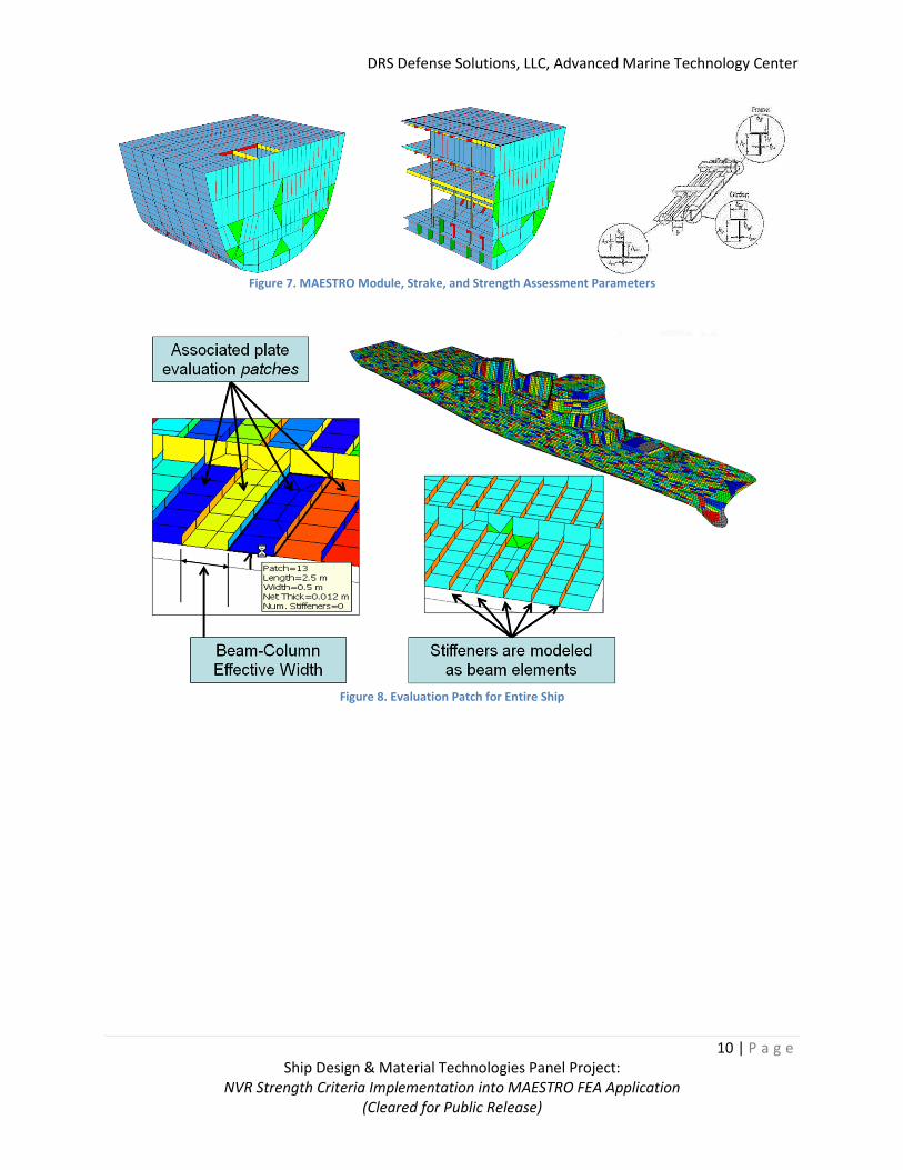
(i.e., one cargo hold or compartment) needs to be built and then copied. Finally, within this module, the
definition of the strake (see Figure 7) is used to capture and retain critical information (e.g., breadth
between stiffeners, span of longitudinals, frames, or girders) for the process of strength assessment.
DRS Defense Solutions, LLC, Advanced Marine Technology Center
9 | P a g e
Ship Design & Material Technologies Panel Project:
NVR Strength Criteria Implementation into MAESTRO FEA Application
(Cleared for Public Release)
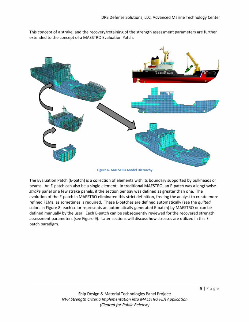
This concept of a strake, and the recovery/retaining of the strength assessment parameters are further
extended to the concept of a MAESTRO Evaluation Patch.
Figure 6. MAESTRO Model Hierarchy
The Evaluation Patch (E-patch) is a collection of elements with its boundary supported by bulkheads or
beams. An E-patch can also be a single element. In traditional MAESTRO, an E-patch was a lengthwise
strake panel or a few strake panels, if the section per bay was defined as greater than one. The
evolution of the E-patch in MAESTRO eliminated this strict definition, freeing the analyst to create more
refined FEMs, as sometimes is required. These E-patches are defined automatically (see the quilted
colors in Figure 8; each color represents an automatically generated E-patch) by MAESTRO or can be
defined manually by the user. Each E-patch can be subsequently reviewed for the recovered strength
assessment parameters (see Figure 9). Later sections will discuss how stresses are utilized in this E-
patch paradigm.
DRS Defense Solutions, LLC, Advanced Marine Technology Center
10 | P a g e
Ship Design & Material Technologies Panel Project:
NVR Strength Criteria Implementation into MAESTRO FEA Application
(Cleared for Public Release)
Figure 7. MAESTRO Module, Strake, and Strength Assessment Parameters
Figure 8. Evaluation Patch for Entire Ship
DRS Defense Solutions, LLC, Advanced Marine Technology Center
11 | P a g e
Ship Design & Material Technologies Panel Project:
NVR Strength Criteria Implementation into MAESTRO FEA Application
(Cleared for Public Release)
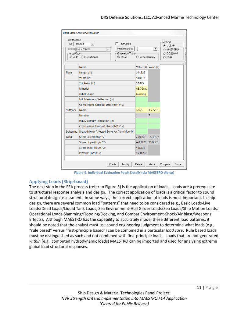
Figure 9. Individual Evaluation Patch Details (via MAESTRO dialog)
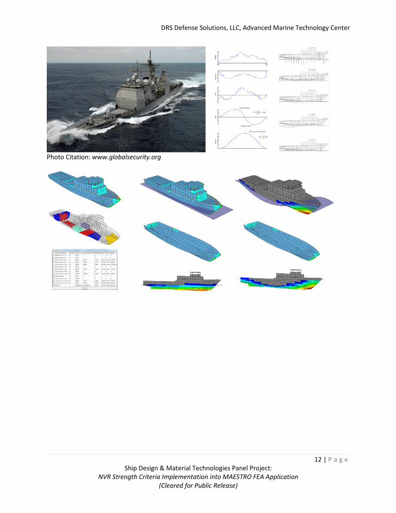
Applying Loads (Ship-based)
The next step in the FEA process (refer to Figure 5) is the application of loads. Loads are a prerequisite
to structural response analysis and design. The correct application of loads is a critical factor to sound
structural design assessment. In some ways, the correct application of loads is most important. In ship
design, there are several common load “patterns” that need to be considered (e.g., Basic Loads-Live
Loads/Dead Loads/Liquid Tank Loads, Sea Environment-Hull Girder Loads/Sea Loads/Ship Motion Loads,
Operational Loads-Slamming/Flooding/Docking, and Combat Environment-Shock/Air blast/Weapons
Effects). Although MAESTRO has the capability to accurately model these different load patterns, it
should be noted that the analyst must use sound engineering judgment to determine what loads (e.g.,
“rule based” versus “first-principle based”) can be combined in a particular load case. Rule based loads
must be distinguished as such and not combined with first-principle loads. Loads that are not generated
within (e.g., computed hydrodynamic loads) MAESTRO can be imported and used for analyzing extreme
global load structural responses.
DRS Defense Solutions, LLC, Advanced Marine Technology Center
12 | P a g e
Ship Design & Material Technologies Panel Project:
NVR Strength Criteria Implementation into MAESTRO FEA Application
(Cleared for Public Release)
Photo Citation: www.globalsecurity.org
DRS Defense Solutions, LLC, Advanced Marine Technology Center
13 | P a g e
Ship Design & Material Technologies Panel Project:
NVR Strength Criteria Implementation into MAESTRO FEA Application
(Cleared for Public Release)
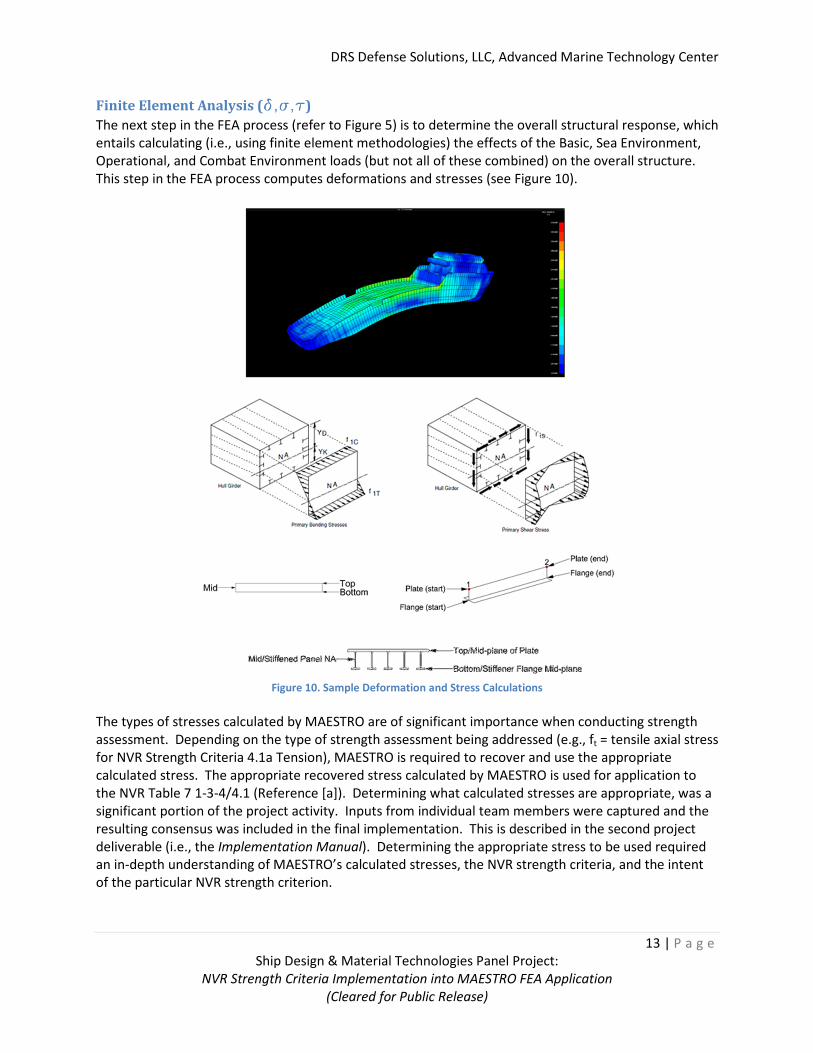
Finite Element Analysis (d,s,td,s,td,s,td,s,t)
The next step in the FEA process (refer to Figure 5) is to determine the overall structural response, which
entails calculating (i.e., using finite element methodologies) the effects of the Basic, Sea Environment,
Operational, and Combat Environment loads (but not all of these combined) on the overall structure.
This step in the FEA process computes deformations and stresses (see Figure 10).
Figure 10. Sample Deformation and Stress Calculations
The types of stresses calculated by MAESTRO are of significant importance when conducting strength
assessment. Depending on the type of strength assessment being addressed (e.g., ft = tensile axial stress
for NVR Strength Criteria 4.1a Tension), MAESTRO is required to recover and use the appropriate
calculated stress. The appropriate recovered stress calculated by MAESTRO is used for application to
the NVR Table 7 1-3-4/4.1 (Reference [a]). Determining what calculated stresses are appropriate, was a
significant portion of the project activity. Inputs from individual team members were captured and the
resulting consensus was included in the final implementation. This is described in the second project
deliverable (i.e., the Implementation Manual). Determining the appropriate stress to be used required
an in-depth understanding of MAESTRO’s calculated stresses, the NVR strength criteria, and the intent
of the particular NVR strength criterion.
DRS Defense Solutions, LLC, Advanced Marine Technology Center
14 | P a g e
Ship Design & Material Technologies Panel Project:
NVR Strength Criteria Implementation into MAESTRO FEA Application
(Cleared for Public Release)
Strength Assessment (Yielding, Buckling)
The final step in the FEA process (refer to Figure 5) is to perform comprehensive strength assessment,
which includes evaluating yielding (��,��) and buckling (���, �������) failure modes. For a given ship
structural system and pertinent loading conditions, the calculated stresses must not be greater than the
limits prescribed and/or computed for these failure modes.
Adequacy Parameters as a Measure of Safety
For the structural system to be deemed safe under a given load condition, the load effect Q must remain
below the limiting value QL. The load effect (Q) is the calculated stress(es) found during the FEA.
Depending on the specific criterion, Q can represent � or � + ��. The limiting value (QL) is specified
and/or calculated by MAESTRO in accordance with Table 7 (1-3-4/4.1) Strength Criteria of the NVRs [b].
Expressed mathematically, the requirement specified in 1-3-4/4.1, is � < �� and a strength ratio can be
defined as follows:
� =�
��
By expressing the requirement in a strength ratio, the safety requirement then becomes � < 1. Each of
these requirements specified in 1-3-4/4.1 [b] constitutes a constraint on the ship structural system. For
easier post-processing and evaluation, MAESTRO expresses this constraint in the form of a parameter
called the Adequacy parameter, denoted by �(�) and is defined as:
�(�) =1 − �
1 + �
The advantage of using an adequacy parameter of the strength ratio is that � always lies within the
normalized limits of -1 and +1, whereas � ranges from 0 to ∞. Specifically, �(�) → 1 as � → 0 either as
a result of a very small load or a very large limiting value (��) and at the other extreme, �(�) → −1 as
� → ∞ either as a result of a very large load or a very small limiting value (��). Each of these adequacy
parameters, as specified in 1-3-4/4.1 [b], is available by way of Results menu after NVR evaluation is
executed when the solver is launched.
Strength Ratios as a Measure of Safety
The structural system measure of safety can also be expressed in terms of a Strength Ratio, which is
simply the load effect (Q) divided by the limiting value (QL). Historically, the US Navy structural design
community has used the strength ratio as a measure of structural adequacy. Therefore, MAESTRO’s
NVR strength assessment included exposing the computed strength ratios to the user.
Evaluation Patch (E-patch)
To properly perform this strength assessment, the true stiffened panel, stanchion and/or beam column
are located in the FEM. MAESTRO does this by automatically searching the entire FEM and collects (if
necessary) multiple finite elements (plates or beams) so the true boundary conditions and true
structural spans are represented and used (if required) in automatically calculating the limiting value for
all ship structural members in the FEM. This strength assessment entity (i.e., the Evaluation Patch or E-
patch) was discussed and described in the Finite Element Model section, see Figure 8. As stated
previously, the individual E-patch parameters can be reviewed and/or modified individually using a
MAESTRO accessed dialog, see Figure 9.
DRS Defense Solutions, LLC, Advanced Marine Technology Center
15 | P a g e
Ship Design & Material Technologies Panel Project:
NVR Strength Criteria Implementation into MAESTRO FEA Application
(Cleared for Public Release)
Technical Approach Summary The above describes, in general terms, the FEA process and strength assessment approach/methodology
in MAESTRO. A more detailed description of the NVR Strength Assessment implementation and sample
calculations can be found in the Implementation Manual as well as the Application and User Guide. The
strength assessment implementation undertaken for this NSRP panel project focused on Table 7 (1-3-
4/4.1) of the NVRs. There are a total of 16 equations, hence design constraints (i.e., limiting values, ��),
that were codified for MAESTRO implementation. These 16 parameters cover a variety of load cases
and associated structural element entities as described in the Implementation Manual.
Project Deliverables A number of project deliverables were identified for the panel project. The following sections
summarize the deliverables.
Project White Paper The Project White Paper provides a description of all activities and team member contributions for the
project as well as the background, methodologies, and technical approaches carried out to accomplish
the stated goals of the project. Earlier DRAFTS of the Project White Paper included Appendices that
captured team member inputs in their entirety; however, it was decided amongst the participating team
members that including these full Appendices with the final Project White Paper would have been
redundant. In essence, the Project White Paper is a high level description of the project as a whole.
Technical details are captured in the Implementation Manual, the Example Manual, and the MAESTRO
Help Manual.
Implementation Manual The Implementation Manual provides a technical description of the available stresses and criterion
computed, recovered, and exposed by MAESTRO’s NVR strength criteria software implementation. As a
prerequisite to the Implementation Manual, the user should understand the fundamental concepts to
MAESTRO’s finite element modeling processes and terms, model integrity checks, loading processes,
and stress results. This document is governed by a DISTRIBUTION STATEMENT D classification.
Application User Guide and Examples The Application User Guide and Examples provides a technical description of how to access the
MAESTRO NVR Implementation software, process, and post-process the NVR strength criteria using
finite element analysis methodologies. This document is governed by a DISTRIBUTION STATEMENT D
classification.
DRS Defense Solutions, LLC, Advanced Marine Technology Center
16 | P a g e
Ship Design & Material Technologies Panel Project:
NVR Strength Criteria Implementation into MAESTRO FEA Application
(Cleared for Public Release)
Future NSRP Project Topics This NSRP Panel Project addressed a focused need within the US Naval structural design community.
Potential Topics to pursue include:
• Extend and/or evolve the strength criteria (Table 7 1-3-4/4.1) to be more appropriate for FEA
methods. This should include a review of current literature/approaches.
• What can be learned from past JTDs.
• MAESTRO implementation of NVR 1-3-3 Load Criteria to facilitate the application of loads.
• Development of a NVR Software Program that performs calculations in accordance with Part 1 Hull
and Structures.
DRS Defense Solutions, LLC, Advanced Marine Technology Center
17 | P a g e
Ship Design & Material Technologies Panel Project:
NVR Strength Criteria Implementation into MAESTRO FEA Application
(Cleared for Public Release)
References [a] National Shipbuilding Research Program (http://www.nsrp.org/)
[b] ABS Rules for Building and Classing Naval Vessels, January 2010, Part 1 Hull and Structures
[c] ISSC committee V.5: Naval Ship Design, 16th International Ship and Offshore Structures Congress,
20-25 August 2006
[d] Ship Structure Committee, Report No. SSC-446, Comparative Study of Naval and Commercial Ship
Structure Design Standards, March 21, 2007