Embed Size (px)
Citation preview
U.S. NAVY NWP 3-15
U.S. MARINE CORPS MCWP 3-3.1.2
MINE WARFARE
DEPARTMENT OF THE NAVYOFFICE OF THE CHIEF OF NAVAL OPERATIONS AND
HEADQUARTERS U.S. MARINE CORPS
1 (Reverse Blank) ORIGINAL
PCN 143 000008 000411LP0004120


3 (Reverse Blank) ORIGINAL

August 1996
PUBLICATION NOTICE
1. NWP 3-15/MCWP 3-3.1.2 MINE WARFARE, is available in the Naval Warfare PublicationsLibrary. It is effective upon receipt.
2. Summary: NWP 3-15/MCWP 3-3.1.2 contains information on Mine Warfare for the battle groupor squadron commander and staff. It is intended to bridge the gap between NDP 3, Naval Opera-tions, and the NWP 3-15 (formerly NWP 27 series) Mine Warfare publications.
5 (Reverse Blank) ORIGINAL
ROUTING
Naval Warfare Publications Custodian
Naval warfare publications must be made readilyavailable to all users and other interested personnelwithin the U.S. Navy.
Note to Naval Warfare Publications Custodian
This notice should be duplicated for routing to cognizant personnel in accordance with NWP 1-01.

Mine Warfare
CONTENTS
PageNo.
CHAPTER 1 — GENERAL CONCEPTS
1.1 INTRODUCTION . . . . . . . . . . . . . . . . . . . . . . . . . . . . . . . . . . . . . . . . 1-1
1.2 KEY DEFINITIONS . . . . . . . . . . . . . . . . . . . . . . . . . . . . . . . . . . . . . . . 1-11.2.1 Mine Warfare. . . . . . . . . . . . . . . . . . . . . . . . . . . . . . . . . . . . . . . . . . . 1-21.2.2 Mining . . . . . . . . . . . . . . . . . . . . . . . . . . . . . . . . . . . . . . . . . . . . . . 1-21.2.3 Mine Countermeasures . . . . . . . . . . . . . . . . . . . . . . . . . . . . . . . . . . . . . . 1-2
1.3 MINE WARFARE FORCE ORGANIZATION . . . . . . . . . . . . . . . . . . . . . . . . . 1-21.3.1 Mining . . . . . . . . . . . . . . . . . . . . . . . . . . . . . . . . . . . . . . . . . . . . . . 1-21.3.2 Mine Countermeasures . . . . . . . . . . . . . . . . . . . . . . . . . . . . . . . . . . . . . . 1-31.3.3 Naval Reserve Forces . . . . . . . . . . . . . . . . . . . . . . . . . . . . . . . . . . . . . . 1-6
1.4 NATO/ALLIED COALITION AND COOPERATION. . . . . . . . . . . . . . . . . . . . . 1-61.4.1 Operations . . . . . . . . . . . . . . . . . . . . . . . . . . . . . . . . . . . . . . . . . . . . 1-61.4.2 Non-NATO Operations . . . . . . . . . . . . . . . . . . . . . . . . . . . . . . . . . . . . . 1-61.4.3 Doctrine . . . . . . . . . . . . . . . . . . . . . . . . . . . . . . . . . . . . . . . . . . . . . 1-71.4.4 Support Organizations . . . . . . . . . . . . . . . . . . . . . . . . . . . . . . . . . . . . . . 1-7
1.5 INTERNATIONAL LAW ASPECTS OF MIW. . . . . . . . . . . . . . . . . . . . . . . . . 1-71.5.1 Hague Convention . . . . . . . . . . . . . . . . . . . . . . . . . . . . . . . . . . . . . . . . 1-71.5.2 Other Legal Aspects . . . . . . . . . . . . . . . . . . . . . . . . . . . . . . . . . . . . . . . 1-7
1.6 MINE WARFARE/POLITICAL INTERFACE (Intelligence and Warnings). . . . . . . . . . 1-81.6.1 Threat. . . . . . . . . . . . . . . . . . . . . . . . . . . . . . . . . . . . . . . . . . . . . . . 1-81.6.2 Movement of Forces . . . . . . . . . . . . . . . . . . . . . . . . . . . . . . . . . . . . . . . 1-81.6.3 Delay Arming . . . . . . . . . . . . . . . . . . . . . . . . . . . . . . . . . . . . . . . . . . 1-8
1.7 MINE WARFARE INTERFACE WITH OTHER WARFARE SPECIALTIES . . . . . . . . 1-81.7.1 Mine Warfare Coordinator . . . . . . . . . . . . . . . . . . . . . . . . . . . . . . . . . . . . 1-81.7.2 Strike Warfare . . . . . . . . . . . . . . . . . . . . . . . . . . . . . . . . . . . . . . . . . . 1-91.7.3 Special Operations . . . . . . . . . . . . . . . . . . . . . . . . . . . . . . . . . . . . . . . . 1-91.7.4 Surface Warfare . . . . . . . . . . . . . . . . . . . . . . . . . . . . . . . . . . . . . . . . . 1-91.7.5 Antisubmarine Warfare . . . . . . . . . . . . . . . . . . . . . . . . . . . . . . . . . . . . . 1-91.7.6 Antiair Warfare . . . . . . . . . . . . . . . . . . . . . . . . . . . . . . . . . . . . . . . . . 1-91.7.7 Amphibious Warfare . . . . . . . . . . . . . . . . . . . . . . . . . . . . . . . . . . . . . . . 1-91.7.8 Maritime Interdiction Operations/Law Enforcement Operations. . . . . . . . . . . . . . . . 1-101.7.9 Salvage Forces . . . . . . . . . . . . . . . . . . . . . . . . . . . . . . . . . . . . . . . . . 1-101.7.10 Command and Control Warfare . . . . . . . . . . . . . . . . . . . . . . . . . . . . . . . . 1-101.7.11 Fleet Exercises . . . . . . . . . . . . . . . . . . . . . . . . . . . . . . . . . . . . . . . . . 1-10
1.8 MINE WARFARE/JOINT INTERFACE. . . . . . . . . . . . . . . . . . . . . . . . . . . . 1-101.8.1 Army - Navy . . . . . . . . . . . . . . . . . . . . . . . . . . . . . . . . . . . . . . . . . . 1-10
7 ORIGINAL
1.8.2 Air Force - Navy . . . . . . . . . . . . . . . . . . . . . . . . . . . . . . . . . . . . . . . . 1-111.8.3 Marine Corps - Navy . . . . . . . . . . . . . . . . . . . . . . . . . . . . . . . . . . . . . . 1-111.8.4 Coast Guard - Navy . . . . . . . . . . . . . . . . . . . . . . . . . . . . . . . . . . . . . . . 1-11
1.9 RULES OF ENGAGEMENT. . . . . . . . . . . . . . . . . . . . . . . . . . . . . . . . . . 1-111.9.1 Reconnaissance . . . . . . . . . . . . . . . . . . . . . . . . . . . . . . . . . . . . . . . . . 1-121.9.2 NATO/Allied ROE Interface . . . . . . . . . . . . . . . . . . . . . . . . . . . . . . . . . . 1-121.9.3 ROE Interface with Warfare Specialties Supporting Mine Warfare Forces. . . . . . . . . . . 1-12
CHAPTER 2 — MINING
2.1 ADVANTAGES AND DISADVANTAGES OF MINING OPERATIONS . . . . . . . . . . 2-12.1.1 Advantages . . . . . . . . . . . . . . . . . . . . . . . . . . . . . . . . . . . . . . . . . . . . 2-12.1.2 Disadvantages . . . . . . . . . . . . . . . . . . . . . . . . . . . . . . . . . . . . . . . . . . 2-1
2.2 MINE CLASSIFICATION. . . . . . . . . . . . . . . . . . . . . . . . . . . . . . . . . . . . 2-22.2.1 Final Position in the Water . . . . . . . . . . . . . . . . . . . . . . . . . . . . . . . . . . . . 2-22.2.2 Method of Delivery . . . . . . . . . . . . . . . . . . . . . . . . . . . . . . . . . . . . . . . 2-32.2.3 Method of Actuation . . . . . . . . . . . . . . . . . . . . . . . . . . . . . . . . . . . . . . . 2-4
2.3 COUNTER-COUNTERMEASURE FEATURES. . . . . . . . . . . . . . . . . . . . . . . . 2-52.3.1 Ship Counter . . . . . . . . . . . . . . . . . . . . . . . . . . . . . . . . . . . . . . . . . . . 2-52.3.2 Probability Actuator . . . . . . . . . . . . . . . . . . . . . . . . . . . . . . . . . . . . . . . 2-62.3.3 Delay Arm . . . . . . . . . . . . . . . . . . . . . . . . . . . . . . . . . . . . . . . . . . . . 2-62.3.4 Delay Rise . . . . . . . . . . . . . . . . . . . . . . . . . . . . . . . . . . . . . . . . . . . . 2-62.3.5 Interlook Dormant Period . . . . . . . . . . . . . . . . . . . . . . . . . . . . . . . . . . . . 2-62.3.6 Intercount Dormant Period . . . . . . . . . . . . . . . . . . . . . . . . . . . . . . . . . . . . 2-62.3.7 Live Period . . . . . . . . . . . . . . . . . . . . . . . . . . . . . . . . . . . . . . . . . . . . 2-62.3.8 Dummy Mines . . . . . . . . . . . . . . . . . . . . . . . . . . . . . . . . . . . . . . . . . . 2-62.3.9 Obstructers . . . . . . . . . . . . . . . . . . . . . . . . . . . . . . . . . . . . . . . . . . . . 2-62.3.10 Anechoic Coating/Camouflage. . . . . . . . . . . . . . . . . . . . . . . . . . . . . . . . . . 2-62.3.11 Nonsympathetic Detonation . . . . . . . . . . . . . . . . . . . . . . . . . . . . . . . . . . . 2-72.3.12 Antisweeper . . . . . . . . . . . . . . . . . . . . . . . . . . . . . . . . . . . . . . . . . . . 2-72.3.13 Antirecovery, Self-Destruct, and Antistripping Features . . . . . . . . . . . . . . . . . . . . 2-7
2.4 MINE DAMAGE TO SHIPS . . . . . . . . . . . . . . . . . . . . . . . . . . . . . . . . . . 2-72.4.1 Contact Mine Damage . . . . . . . . . . . . . . . . . . . . . . . . . . . . . . . . . . . . . . 2-72.4.2 Noncontact Mine Damage . . . . . . . . . . . . . . . . . . . . . . . . . . . . . . . . . . . . 2-7
2.5 U.S. NAVY/ALLIED MINES . . . . . . . . . . . . . . . . . . . . . . . . . . . . . . . . . . 2-92.5.1 U.S. Navy Service Mines and Mine Characteristics . . . . . . . . . . . . . . . . . . . . . . . 2-92.5.2 Exercise and Training Mines . . . . . . . . . . . . . . . . . . . . . . . . . . . . . . . . . . 2-112.5.3 Future Mine Potentials . . . . . . . . . . . . . . . . . . . . . . . . . . . . . . . . . . . . . 2-112.5.4 Mine Storage, Preparation, and Transportation. . . . . . . . . . . . . . . . . . . . . . . . . 2-112.5.5 Minefield Planning Process/Procedures . . . . . . . . . . . . . . . . . . . . . . . . . . . . 2-122.5.6 Computer Programs in Use . . . . . . . . . . . . . . . . . . . . . . . . . . . . . . . . . . . 2-14
2.6 U.S./ALLIED MINELAYING ASSETS . . . . . . . . . . . . . . . . . . . . . . . . . . . . 2-152.6.1 Air Delivery . . . . . . . . . . . . . . . . . . . . . . . . . . . . . . . . . . . . . . . . . . . 2-15
ORIGINAL 8
PageNo.
2.6.2 Submarine Delivery . . . . . . . . . . . . . . . . . . . . . . . . . . . . . . . . . . . . . . . 2-162.6.3 Surface Delivery . . . . . . . . . . . . . . . . . . . . . . . . . . . . . . . . . . . . . . . . 2-16
2.7 IMPACT OF ENVIRONMENT ON MINING . . . . . . . . . . . . . . . . . . . . . . . . . 2-172.7.1 Water Depth. . . . . . . . . . . . . . . . . . . . . . . . . . . . . . . . . . . . . . . . . . . 2-172.7.2 Winds . . . . . . . . . . . . . . . . . . . . . . . . . . . . . . . . . . . . . . . . . . . . . . 2-172.7.3 Seas and Swells . . . . . . . . . . . . . . . . . . . . . . . . . . . . . . . . . . . . . . . . . 2-172.7.4 Sea Ice. . . . . . . . . . . . . . . . . . . . . . . . . . . . . . . . . . . . . . . . . . . . . . 2-172.7.5 Tides . . . . . . . . . . . . . . . . . . . . . . . . . . . . . . . . . . . . . . . . . . . . . . 2-172.7.6 Currents . . . . . . . . . . . . . . . . . . . . . . . . . . . . . . . . . . . . . . . . . . . . . 2-172.7.7 Seawater Temperature . . . . . . . . . . . . . . . . . . . . . . . . . . . . . . . . . . . . . 2-172.7.8 Water Transparency. . . . . . . . . . . . . . . . . . . . . . . . . . . . . . . . . . . . . . . 2-172.7.9 Marine Life . . . . . . . . . . . . . . . . . . . . . . . . . . . . . . . . . . . . . . . . . . . 2-172.7.10 Bottom Conditions . . . . . . . . . . . . . . . . . . . . . . . . . . . . . . . . . . . . . . . 2-182.7.11 Magnetic Environment . . . . . . . . . . . . . . . . . . . . . . . . . . . . . . . . . . . . . 2-18
CHAPTER 3 — MINE COUNTERMEASURES
3.1 GENERAL . . . . . . . . . . . . . . . . . . . . . . . . . . . . . . . . . . . . . . . . . . . . 3-1
3.2 OFFENSIVE MINE COUNTERMEASURES . . . . . . . . . . . . . . . . . . . . . . . . . 3-13.2.1 Offensive Mine Countermeasures by Strike Assets . . . . . . . . . . . . . . . . . . . . . . . 3-13.2.2 Mining as an Offensive MINE COUNTERMEASURES Tactic . . . . . . . . . . . . . . . . 3-2
3.3 DEFENSIVE MINE COUNTERMEASURES . . . . . . . . . . . . . . . . . . . . . . . . . 3-3
3.4 PASSIVE MINE COUNTERMEASURES . . . . . . . . . . . . . . . . . . . . . . . . . . . 3-33.4.1 Locating the Threat. . . . . . . . . . . . . . . . . . . . . . . . . . . . . . . . . . . . . . . . 3-33.4.2 Localizing the Threat. . . . . . . . . . . . . . . . . . . . . . . . . . . . . . . . . . . . . . . 3-33.4.3 Reducing the Risk . . . . . . . . . . . . . . . . . . . . . . . . . . . . . . . . . . . . . . . . 3-5
3.5 ACTIVE MINE COUNTERMEASURES . . . . . . . . . . . . . . . . . . . . . . . . . . . . 3-53.5.1 Mine Hunting. . . . . . . . . . . . . . . . . . . . . . . . . . . . . . . . . . . . . . . . . . . 3-53.5.2 Mechanical Minesweeping . . . . . . . . . . . . . . . . . . . . . . . . . . . . . . . . . . . . 3-73.5.3 Influence Minesweeping . . . . . . . . . . . . . . . . . . . . . . . . . . . . . . . . . . . . . 3-93.5.4 Mine Neutralization . . . . . . . . . . . . . . . . . . . . . . . . . . . . . . . . . . . . . . . 3-143.5.5 Mine Exploitation . . . . . . . . . . . . . . . . . . . . . . . . . . . . . . . . . . . . . . . . 3-153.5.6 Brute Force Mine Clearance . . . . . . . . . . . . . . . . . . . . . . . . . . . . . . . . . . 3-15
3.6 INTEGRATED MINE COUNTERMEASURES OPERATIONS . . . . . . . . . . . . . . . 3-16
3.7 COMBINED MINE COUNTERMEASURES OPERATIONS . . . . . . . . . . . . . . . . 3-163.7.1 Primary NATO/Allied Mine Countermeasures Assets . . . . . . . . . . . . . . . . . . . . . 3-173.7.2 Other Mine Countermeasures Forces . . . . . . . . . . . . . . . . . . . . . . . . . . . . . . 3-19
3.8 AMPHIBIOUS MINE COUNTERMEASURES OPERATIONS . . . . . . . . . . . . . . . 3-21
3.9 SUBMARINE MINE COUNTERMEASURES OPERATIONS . . . . . . . . . . . . . . . 3-22
3.10 RIVERINE MINE COUNTERMEASURES OPERATIONS . . . . . . . . . . . . . . . . . 3-22
9 ORIGINAL
PageNo.
3.11 DEPLOYMENT OF MINE COUNTERMEASURES FORCES . . . . . . . . . . . . . . . 3-233.11.1 Surface Mine Countermeasures Forces . . . . . . . . . . . . . . . . . . . . . . . . . . . . . 3-233.11.2 Airborne Mine Countermeasures Forces . . . . . . . . . . . . . . . . . . . . . . . . . . . . 3-243.11.3 Underwater Mine Countermeasures Forces . . . . . . . . . . . . . . . . . . . . . . . . . . 3-253.11.4 Mine Countermeasures Staff . . . . . . . . . . . . . . . . . . . . . . . . . . . . . . . . . . 3-37
3.12 INTERFACE WITH THE ENVIRONMENT . . . . . . . . . . . . . . . . . . . . . . . . . 3-283.12.1 General/Introduction . . . . . . . . . . . . . . . . . . . . . . . . . . . . . . . . . . . . . . 3-283.12.2 Environmental Factors . . . . . . . . . . . . . . . . . . . . . . . . . . . . . . . . . . . . . 3-283.12.3 Environmental Effects on Mine Warfare Weapons, Systems, and Decisions . . . . . . . . . 3-283.12.4 Environmental Data Collection . . . . . . . . . . . . . . . . . . . . . . . . . . . . . . . . . 3-32
3.13 MINE COUNTERMEASURES FORCE COMMAND AND CONTROL . . . . . . . . . . 3-343.13.1 Concept of Operations . . . . . . . . . . . . . . . . . . . . . . . . . . . . . . . . . . . . . 3-343.13.2 Mine Countermeasures Staff Organization . . . . . . . . . . . . . . . . . . . . . . . . . . . 3-353.13.3 The Mine Countermeasures Command Center . . . . . . . . . . . . . . . . . . . . . . . . . 3-353.13.4 Mine Warfare C4I Systems . . . . . . . . . . . . . . . . . . . . . . . . . . . . . . . . . . . 3-363.13.5 Mine Countermeasures Planning . . . . . . . . . . . . . . . . . . . . . . . . . . . . . . . . 3-363.13.6 Mine Countermeasures Exercises. . . . . . . . . . . . . . . . . . . . . . . . . . . . . . . . 3-373.13.7 Mine Countermeasures Exercise Analysis . . . . . . . . . . . . . . . . . . . . . . . . . . . 3-37
CHAPTER 4 — MINE COUNTERMEASURES FOR NON-MINE COUNTERMEASURES SHIPS
4.1 CONCEPTS . . . . . . . . . . . . . . . . . . . . . . . . . . . . . . . . . . . . . . . . . . . 4-14.1.1 Detect and Avoid . . . . . . . . . . . . . . . . . . . . . . . . . . . . . . . . . . . . . . . . . 4-14.1.2 Use of the Environment . . . . . . . . . . . . . . . . . . . . . . . . . . . . . . . . . . . . . 4-14.1.3 Organic Mine Countermeasures . . . . . . . . . . . . . . . . . . . . . . . . . . . . . . . . . 4-14.1.4 In-Stride Mine Countermeasures. . . . . . . . . . . . . . . . . . . . . . . . . . . . . . . . . 4-1
4.2 SYSTEMS AND PROCEDURES . . . . . . . . . . . . . . . . . . . . . . . . . . . . . . . . 4-24.2.1 Battle Group Capabilities . . . . . . . . . . . . . . . . . . . . . . . . . . . . . . . . . . . . 4-24.2.2 Moored or Drifting Mine Self-Protection . . . . . . . . . . . . . . . . . . . . . . . . . . . . 4-24.2.3 Electromagnetic Self-Protection . . . . . . . . . . . . . . . . . . . . . . . . . . . . . . . . . 4-34.2.4 Acoustic Self-Protection . . . . . . . . . . . . . . . . . . . . . . . . . . . . . . . . . . . . . 4-44.2.5 Seismic Self-Protection . . . . . . . . . . . . . . . . . . . . . . . . . . . . . . . . . . . . . 4-44.2.6 Pressure Self-Protection . . . . . . . . . . . . . . . . . . . . . . . . . . . . . . . . . . . . . 4-5
4.3 TACTICS . . . . . . . . . . . . . . . . . . . . . . . . . . . . . . . . . . . . . . . . . . . . 4-54.3.1 Ship’s Self-Protection . . . . . . . . . . . . . . . . . . . . . . . . . . . . . . . . . . . . . . 4-54.3.2 Drifting/Contact Mine Tactics . . . . . . . . . . . . . . . . . . . . . . . . . . . . . . . . . . 4-54.3.3 Moored Mine Tactics. . . . . . . . . . . . . . . . . . . . . . . . . . . . . . . . . . . . . . . 4-54.3.4 Magnetic Mine Tactics . . . . . . . . . . . . . . . . . . . . . . . . . . . . . . . . . . . . . . 4-64.3.5 Acoustic/Seismic Mine Tactics . . . . . . . . . . . . . . . . . . . . . . . . . . . . . . . . . 4-64.3.6 Pressure Mine Tactics . . . . . . . . . . . . . . . . . . . . . . . . . . . . . . . . . . . . . . 4-64.3.7 Group’s Self-Protection Tactics . . . . . . . . . . . . . . . . . . . . . . . . . . . . . . . . . 4-74.3.8 Preplanned Responses . . . . . . . . . . . . . . . . . . . . . . . . . . . . . . . . . . . . . . 4-74.3.9 Mine Disposal . . . . . . . . . . . . . . . . . . . . . . . . . . . . . . . . . . . . . . . . . . 4-7
4.4 PASSIVE MINE COUNTERMEASURES FOR SUBMARINES . . . . . . . . . . . . . . . 4-8
ORIGINAL 10
PageNo.
APPENDIX A — MINE WARFARE TERMINOLOGY . . . . . . . . . . . . . . . . . . . . . . . . . . A-1
APPENDIX B — MINE WARFARE PROGRAM AND SUPPORT ORGANIZATION . . . . . . . . . B-1
APPENDIX C — MINE WARFARE HISTORICAL PERSPECTIVE . . . . . . . . . . . . . . . . . . . C-1
APPENDIX D — U.S. MINES . . . . . . . . . . . . . . . . . . . . . . . . . . . . . . . . . . . . . . . . D-1
APPENDIX E — MINE WARFARE REFERENCES . . . . . . . . . . . . . . . . . . . . . . . . . . . . E-1
INDEX . . . . . . . . . . . . . . . . . . . . . . . . . . . . . . . . . . . . . . . . . . . . . . . . . . . . Index-1
11 ORIGINAL
PageNo.
LIST OF ILLUSTRATIONS
PageNo.
CHAPTER 1 — GENERAL CONCEPTS
Figure 1-1 Mine Storage and Preparation Organization . . . . . . . . . . . . . . . . . . . . . . . 1-3Figure 1-2 Mine Countermeasures Operational Forces . . . . . . . . . . . . . . . . . . . . . . . . 1-5
CHAPTER 2 — MINING
Figure 2-1 Environmental Considerations in Mining . . . . . . . . . . . . . . . . . . . . . . . . 2-18
CHAPTER 3 — MINE COUNTERMEASURES
Figure 3-1 Mine Countermeasures Family Tree . . . . . . . . . . . . . . . . . . . . . . . . . . . 3-2Figure 3-2 Localization of Threat by Q-Route . . . . . . . . . . . . . . . . . . . . . . . . . . . . 3-4Figure 3-3 AN/SQQ-32 Minehunting Sonar . . . . . . . . . . . . . . . . . . . . . . . . . . . . . 3-8Figure 3-4 MH-53E with AN/AQS-14 Sonar . . . . . . . . . . . . . . . . . . . . . . . . . . . . . 3-8Figure 3-5 AN/SLQ-38 Mechanical Sweep . . . . . . . . . . . . . . . . . . . . . . . . . . . . . 3-10Figure 3-6 A/N37-U Controlled Depth Sweep/AN/SLQ-53 Single Ship
Deep Sweep . . . . . . . . . . . . . . . . . . . . . . . . . . . . . . . . . . . . . . . 3-11Figure 3-7 AN/SLQ-37 Combination Influence Sweep . . . . . . . . . . . . . . . . . . . . . . . 3-12Figure 3-8 MH-53E with Mk-105 Magnetic Minesweeping System . . . . . . . . . . . . . . . . 3-13Figure 3-9 Other Mine Countermeasures Assets . . . . . . . . . . . . . . . . . . . . . . . . . . 3-20Figure 3-10 Environmental Considerations in Mine Countermeasures. . . . . . . . . . . . . . . . 3-29
CHAPTER 4 — MINE COUNTERMEASURES FOR NON-MINECOUNTERMEASURES SHIPS
Figure 4-1 U.S. Navy Magnetic Silencing Facilities . . . . . . . . . . . . . . . . . . . . . . . . . 4-4
APPENDIX B — MINE WARFARE PROGRAM AND SUPPORTORGANIZATION
Figure B-1 Mine Warfare Program Organization. . . . . . . . . . . . . . . . . . . . . . . . . . . B-2
ORIGINAL 12

RECORD OF CHANGES
Change No. andDate of Change
Date of EntryPage Count Verified
by (Signature)
13 ORIGINAL

RECORD OF CHANGES
Change No. andDate of Change
Date of EntryPage Count Verified
by (Signature)
ORIGINAL 14
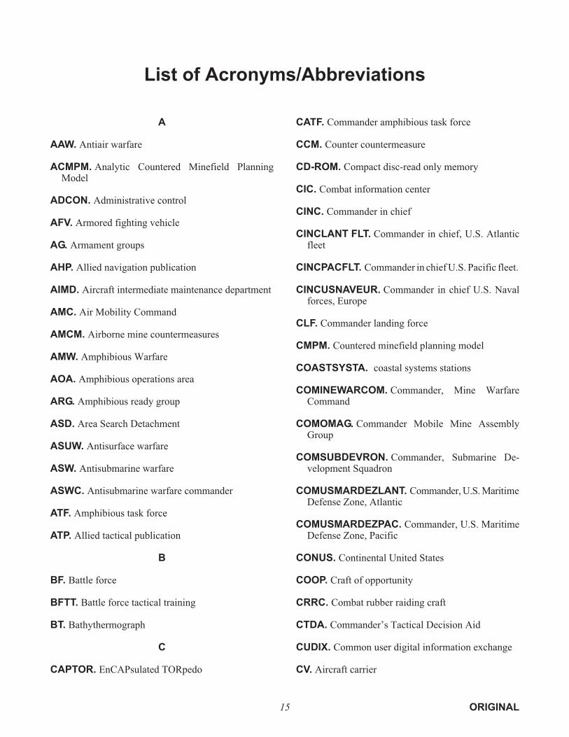
List of Acronyms/Abbreviations
A
AAW. Antiair warfare
ACMPM. Analytic Countered Minefield PlanningModel
ADCON. Administrative control
AFV. Armored fighting vehicle
AG. Armament groups
AHP. Allied navigation publication
AIMD. Aircraft intermediate maintenance department
AMC. Air Mobility Command
AMCM. Airborne mine countermeasures
AMW. Amphibious Warfare
AOA. Amphibious operations area
ARG. Amphibious ready group
ASD. Area Search Detachment
ASUW. Antisurface warfare
ASW. Antisubmarine warfare
ASWC. Antisubmarine warfare commander
ATF. Amphibious task force
ATP. Allied tactical publication
B
BF. Battle force
BFTT. Battle force tactical training
BT. Bathythermograph
C
CAPTOR. EnCAPsulated TORpedo
CATF. Commander amphibious task force
CCM. Counter countermeasure
CD-ROM. Compact disc-read only memory
CIC. Combat information center
CINC. Commander in chief
CINCLANT FLT. Commander in chief, U.S. Atlanticfleet
CINCPACFLT. Commander in chief U.S. Pacific fleet.
CINCUSNAVEUR. Commander in chief U.S. Navalforces, Europe
CLF. Commander landing force
CMPM. Countered minefield planning model
COASTSYSTA. coastal systems stations
COMINEWARCOM. Commander, Mine WarfareCommand
COMOMAG. Commander Mobile Mine AssemblyGroup
COMSUBDEVRON. Commander, Submarine De-velopment Squadron
COMUSMARDEZLANT. Commander, U.S. MaritimeDefense Zone, Atlantic
COMUSMARDEZPAC. Commander, U.S. MaritimeDefense Zone, Pacific
CONUS. Continental United States
COOP. Craft of opportunity
CRRC. Combat rubber raiding craft
CTDA. Commander’s Tactical Decision Aid
CUDIX. Common user digital information exchange
CV. Aircraft carrier
15 ORIGINAL
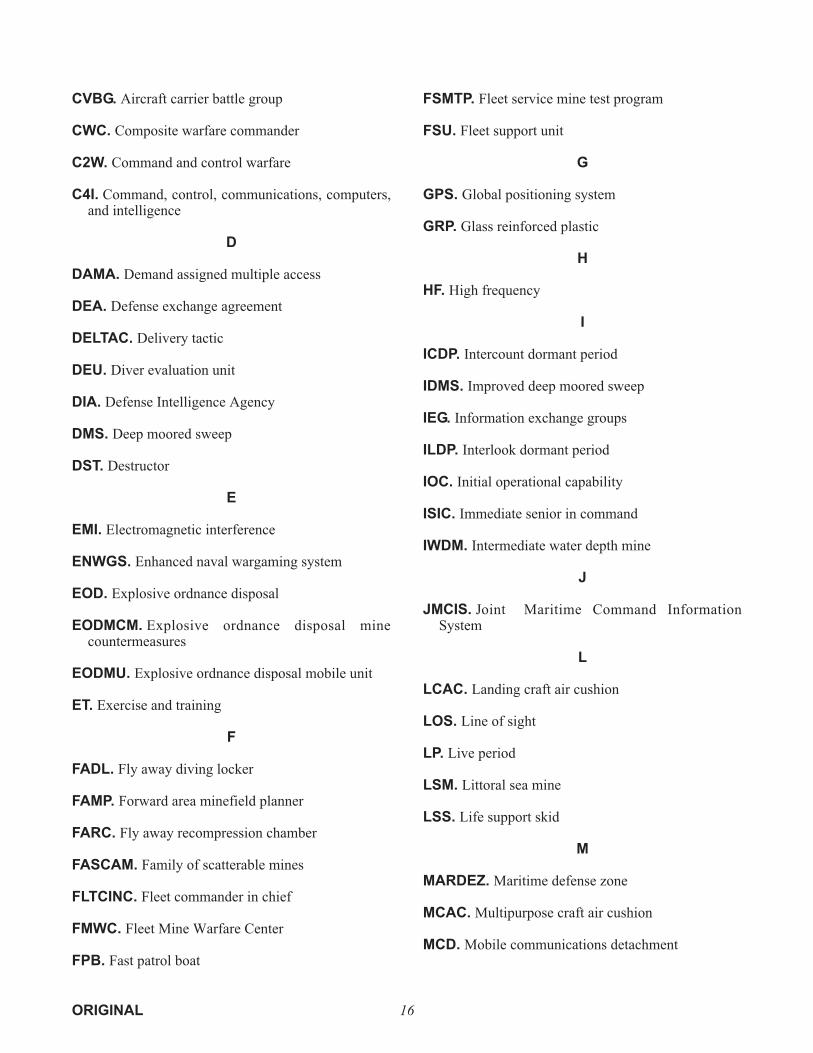
CVBG. Aircraft carrier battle group
CWC. Composite warfare commander
C2W. Command and control warfare
C4I. Command, control, communications, computers,and intelligence
D
DAMA. Demand assigned multiple access
DEA. Defense exchange agreement
DELTAC. Delivery tactic
DEU. Diver evaluation unit
DIA. Defense Intelligence Agency
DMS. Deep moored sweep
DST. Destructor
E
EMI. Electromagnetic interference
ENWGS. Enhanced naval wargaming system
EOD. Explosive ordnance disposal
EODMCM. Explosive ordnance disposal minecountermeasures
EODMU. Explosive ordnance disposal mobile unit
ET. Exercise and training
F
FADL. Fly away diving locker
FAMP. Forward area minefield planner
FARC. Fly away recompression chamber
FASCAM. Family of scatterable mines
FLTCINC. Fleet commander in chief
FMWC. Fleet Mine Warfare Center
FPB. Fast patrol boat
FSMTP. Fleet service mine test program
FSU. Fleet support unit
G
GPS. Global positioning system
GRP. Glass reinforced plastic
H
HF. High frequency
I
ICDP. Intercount dormant period
IDMS. Improved deep moored sweep
IEG. Information exchange groups
ILDP. Interlook dormant period
IOC. Initial operational capability
ISIC. Immediate senior in command
IWDM. Intermediate water depth mine
J
JMCIS. Joint Maritime Command InformationSystem
L
LCAC. Landing craft air cushion
LOS. Line of sight
LP. Live period
LSM. Littoral sea mine
LSS. Life support skid
M
MARDEZ. Maritime defense zone
MCAC. Multipurpose craft air cushion
MCD. Mobile communications detachment
ORIGINAL 16
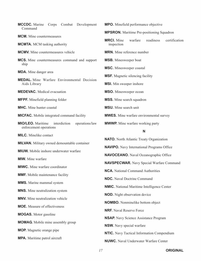
MCCDC. Marine Corps Combat DevelopmentCommand
MCM. Mine countermeasures
MCMTA. MCM tasking authority
MCMV. Mine countermeasures vehicle
MCS. Mine countermeasures command and supportship
MDA. Mine danger area
MEDAL. Mine Warfare Environmental DecisionAids Library
MEDEVAC. Medical evacuation
MFPF. Minefield planning folder
MHC. Mine hunter coastal
MICFAC. Mobile integrated command facility
MIO/LEO. Maritime interdiction operations/lawenforcement operations
MILC. Minelike contact
MILVAN. Military owned demountable container
MIUW. Mobile inshore underwater warfare
MIW. Mine warfare
MIWC. Mine warfare coordinator
MMF. Mobile maintenance facility
MMS. Marine mammal system
MNS. Mine neutralization system
MNV. Mine neutralization vehicle
MOE. Measure of effectiveness
MOGAS. Motor gasoline
MOMAG. Mobile mine assembly group
MOP. Magnetic orange pipe
MPA. Maritime patrol aircraft
MPO. Minefield performance objective
MPSRON. Maritime Pre-positioning Squadron
MRCI. Mine warfare readiness certificationinspection
MRN. Mine reference number
MSB. Minesweeper boat
MSC. Minesweeper coastal
MSF. Magnetic silencing facility
MSI. Min sweeper inshore
MSO. Minesweeper ocean
MSS. Mine search squadron
MSU. Mine search unit
MWES. Mine warfare environmental survey
MWWP. Mine warfare working party
N
NATO. North Atlantic Treaty Organization
NAVIPO. Navy International Programs Office
NAVOCEANO. Naval Oceanographic Office
NAVSPECWAR. Navy Special Warfare Command
NCA. National Command Authorities
NDC. Naval Doctrine Command
NMIC. National Maritime Intelligence Center
NOD. Night observation device
NOMBO. Nonminelike bottom object
NRF. Naval Reserve Force
NSAP. Navy Science Assistance Program
NSW. Navy special warfare
NTIC. Navy Tactical Information Compendium
NUWC. Naval Underwater Warfare Center
17 ORIGINAL
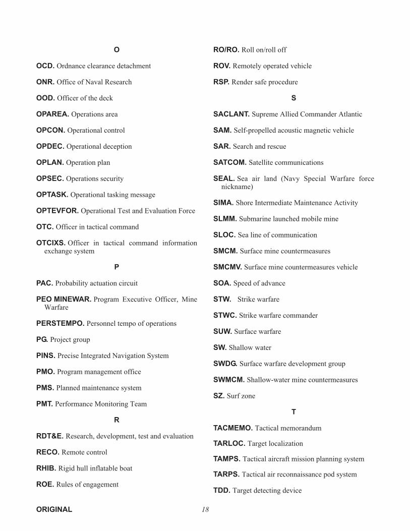
O
OCD. Ordnance clearance detachment
ONR. Office of Naval Research
OOD. Officer of the deck
OPAREA. Operations area
OPCON. Operational control
OPDEC. Operational deception
OPLAN. Operation plan
OPSEC. Operations security
OPTASK. Operational tasking message
OPTEVFOR. Operational Test and Evaluation Force
OTC. Officer in tactical command
OTCIXS. Officer in tactical command informationexchange system
P
PAC. Probability actuation circuit
PEO MINEWAR. Program Executive Officer, MineWarfare
PERSTEMPO. Personnel tempo of operations
PG. Project group
PINS. Precise Integrated Navigation System
PMO. Program management office
PMS. Planned maintenance system
PMT. Performance Monitoring Team
R
RDT&E. Research, development, test and evaluation
RECO. Remote control
RHIB. Rigid hull inflatable boat
ROE. Rules of engagement
RO/RO. Roll on/roll off
ROV. Remotely operated vehicle
RSP. Render safe procedure
S
SACLANT. Supreme Allied Commander Atlantic
SAM. Self-propelled acoustic magnetic vehicle
SAR. Search and rescue
SATCOM. Satellite communications
SEAL. Sea air land (Navy Special Warfare forcenickname)
SIMA. Shore Intermediate Maintenance Activity
SLMM. Submarine launched mobile mine
SLOC. Sea line of communication
SMCM. Surface mine countermeasures
SMCMV. Surface mine countermeasures vehicle
SOA. Speed of advance
STW. Strike warfare
STWC. Strike warfare commander
SUW. Surface warfare
SW. Shallow water
SWDG. Surface warfare development group
SWMCM. Shallow-water mine countermeasures
SZ. Surf zone
T
TACMEMO. Tactical memorandum
TARLOC. Target localization
TAMPS. Tactical aircraft mission planning system
TARPS. Tactical air reconnaissance pod system
TDD. Target detecting device
ORIGINAL 18
TGO. Tactical group ORESTES
TLAM. Tomahawk land attack missile
TPFDD. Time Phased Force Deployment Data
TPFDL. Time Phased Force Deployment List
U
UBA. Underwater breathing apparatus
UEP. Underwater electric potential
UHF. Ultra high frequency
UMCM. Underwater mine countermeasures
UMPM. Uncountered minefield planning model
V
VDS. Variable depth sonar
VEMS. Versatile exercise mine system
VHF. Very high frequency
VLCC. Very large crude carrier
VMFI. Visual mine firing indicator
VSW. Very shallow water
19 (Reverse Blank) ORIGINAL

PREFACE
NWP 3-15/MCWP 3-3.1.2 Mine Warfare, has beenbrought into existence to give a broad command over-view of Mine Warfare and to provide a link to otherdocuments critical to the understanding and planningprocesses.
Throughout this publication, references to otherpublications imply the effective edition.
Report any page shortage by letter to Commander,Navy Warfare Development Command.
ORDERING DATA
Order a new publication or change, as appropriate,through the Navy Supply System.
Changes to the distribution and allowance lists (to addor delete your command from the distribution list, or tomodify the number of copies of a publication that you re-ceive) must be made in accordance with NTTP 1-01.
RECOMMENDED CHANGES
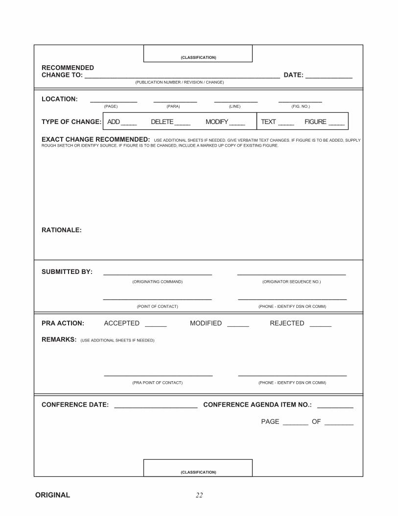
Recommended changes to this publication may besubmitted at any time using the accompanying formatfor routine changes.
Atlantic and Pacific fleet units and stations and allother units and CONUS shore activities submit recom-mendations to:
COMMANDER MINE WARFARE COMMAND325 FIFTH STREET SECORPUS CHRISTI TX 78419-5032
U.S. Marine Corps Unit submit recommendationsto:
COMMANDING GENERAL (WF06)MARINE CORPS COMBAT DEVELOPMENTCOMMANDQUANTICO VA 22134-5001
In addition, forward two copies of all recommenda-tions to:
COMMANDERNAVWARDEVCOM686 CUSHING RDNEWPORT RI 02841-1207
URGENT CHANGE RECOMMENDATIONS
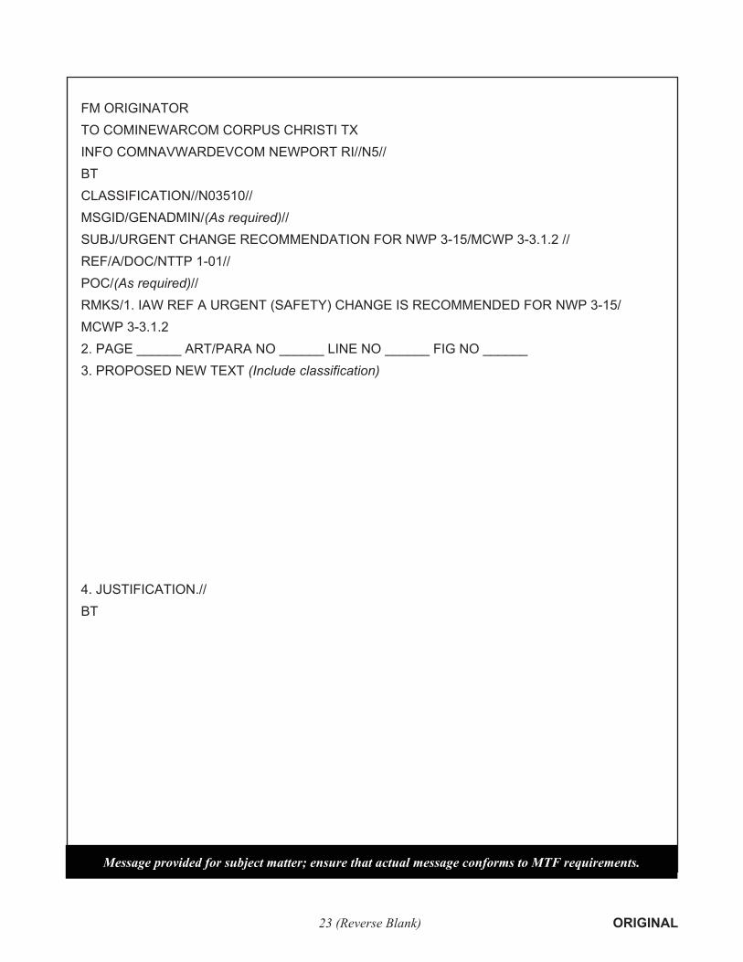
When items for changes are considered to be urgent(as defined in NTTP 1-01, and including matters ofsafety), this information shall be sent by message (seeaccompanying sample message format) to PRA, withinformation copies to Navy Warfare DevelopmentCommand, and all other commands concerned, clearlyexplaining the proposed change. Information address-ees should comment as appropriate. See NTTP 1-01.
CHANGE SYMBOLS
Revised text in changes is indicated by a black verti-cal line in either margin of the page, like the one printednext to this paragraph. The change symbol showswhere there has been a change. The change might bematerial added or information restated. A change sym-bol in the margin by the chapter number and title indi-cates a new or completely revised chapter.
21 ORIGINAL
ORIGINAL 22
(CLASSIFICATION)
RECOMMENDEDCHANGE TO: ______________________________________________________ DATE: _____________
(PUBLICATION NUMBER / REVISION / CHANGE)
LOCATION: _____________ ____________ ____________ ____________(PAGE) (PARA) (LINE) (FIG. NO.)
TYPE OF CHANGE: ADD_____ DELETE_____ MODIFY_____ TEXT _____ FIGURE _____
EXACT CHANGE RECOMMENDED: USE ADDITIONAL SHEETS IF NEEDED. GIVE VERBATIM TEXT CHANGES. IF FIGURE IS TO BE ADDED, SUPPLY
ROUGH SKETCH OR IDENTIFY SOURCE. IF FIGURE IS TO BE CHANGED, INCLUDE A MARKED UP COPY OF EXISTING FIGURE.
RATIONALE:
SUBMITTED BY: ______________________________ ______________________________
(ORIGINATING COMMAND) (ORIGINATOR SEQUENCE NO.)
______________________________ ______________________________
(POINT OF CONTACT) (PHONE - IDENTIFY DSN OR COMM)
PRA ACTION: ACCEPTED ______ MODIFIED ______ REJECTED ______
REMARKS: (USE ADDITIONAL SHEETS IF NEEDED)
______________________________ ______________________________
(PRA POINT OF CONTACT) (PHONE - IDENTIFY DSN OR COMM)
CONFERENCE DATE: _______________________ CONFERENCE AGENDA ITEM NO.: __________
PAGE _______ OF ________
(CLASSIFICATION)
23 (Reverse Blank) ORIGINAL
FM ORIGINATOR
TO COMINEWARCOM CORPUS CHRISTI TX
INFO COMNAVWARDEVCOM NEWPORT RI//N5//
BT
CLASSIFICATION//N03510//
MSGID/GENADMIN/(As required)//
SUBJ/URGENT CHANGE RECOMMENDATION FOR NWP 3-15/MCWP 3-3.1.2 //
REF/A/DOC/NTTP 1-01//
POC/(As required)//
RMKS/1. IAW REF A URGENT (SAFETY) CHANGE IS RECOMMENDED FOR NWP 3-15/
MCWP 3-3.1.2
2. PAGE ______ ART/PARA NO ______ LINE NO ______ FIG NO ______
3. PROPOSED NEW TEXT (Include classification)
4. JUSTIFICATION.//
BT
Message provided for subject matter; ensure that actual message conforms to MTF requirements.

CHAPTER 1
General Concepts
1.1 INTRODUCTION
This publication has been brought into existence togive a broad command overview of Mine Warfare andto provide a link to other documents critical to the un-derstanding and planning processes. Its ultimate pur-pose, therefore, is to play a supporting role in keepingthe Mine Warfare lessons learned truly learned. It maythereby aid in the avoidance of such unfortunate tacti-cal situations as befell USS PRINCETON (CG 59),USS TRIPOLI (LPH 10), and USS SAMUEL B. ROB-ERTS (FFG 58). In future naval engagements with anenemy, especially in joint littoral warfare, mines arecertain to play an important role. It is imperative tominimize the potential loss of human life and warshipsand to enhance the smooth integration, coordination,and effectiveness of the mine warfighting element tosupport overall military force and political objectives.
Since the invention of the Bushnell Keg in 1776,mine warfare has been an important element of navalwarfare. The use of mines and countermeasures tomines has figured significantly in every major armedconflict and nearly every regional conflict in which theUnited States has been involved since the Revolution-ary War. Mine warfare has been increasingly importantand effective since World War I. Mines presently onthe world arms markets are relatively inexpensive, easyto procure, reliable and effective, and difficult for intel-ligence agencies to track. The mine, as a weapon sys-tem, has an extremely favorable investment return (costof mine to cost of damage ratio) for the miner.
Despite the logic and effectiveness of maintainingthe mine element of war at sea on an even footing withthe other naval warfighting specialties, throughout itshistory, the U.S. Navy has devoted proportionallyfewer resources to mine warfare. As a result, despite theemergence of the U.S. Navy as the world’s premiermaritime power whose individual warfighting capabili-ties generally are superior to those of other navies, itsmine countermeasure capabilities have lagged behind.
The old adage that those who will not learn the les-sons of history are doomed to repeat them has persis-tently applied to the mine warfare aspect of the U.S.Navy. North Arabian Gulf operations of the U.S. Navyin Desert Storm contain some bitter experiences, in-cluding the mission-aborting mine strikes to two majorwarships, as well as the controversy over the decisionnot to land U.S. Marines in Kuwait. Despite the unfor-tunate nature of the initial Desert Storm experience andthe need to recapture expertise in MCM, the U.S. Navyand Allied navies did have substantial success in coun-tering the nearly 1,300 naval mines deployed by theIraqis and emerged victorious in the MCM element ofDesert Storm warfighting as in the other aspects of thatwar.
This positive conclusion to the mine clearance cam-paign in the North Arabian Gulf was because of the un-paralleled material and logistics support from theDepartment of the Navy’s shore establishment and thecooperation of many allied nations in the coalition ef-fort. In addition to national support and multinationalcooperation, the enabling elements of this success werethe ability of the American Bluejacket to learn andadapt quickly, combined with good tactical commandin the fields. Of special note is that as the course of themine clearance campaign progressed, the Naval Com-ponent Command leadership came to understand, ap-preciate, and support the complex warfighting nature ofmine clearance operations.
1.2 KEY DEFINITIONS
Mine warfare uses many terms that, although theymay appear in other warfare areas, carry different ormore specific definitions when applied to mine war-fare. Additionally, there are terms used by Allied minewarfare forces that seem similar to U.S. terms but thatdiffer to some extent. Allied or coalition force opera-tions can be far more difficult when the forces and com-manders are not able to communicate freely because ofthe misunderstandings caused by different terminology.Therefore, it is important for the commander to becomefamiliar with the various terms that may be employedwhen discussing and planning mine warfare operations.
1-1 ORIGINAL
Appendix A contains terminology used in mine warfarethat is not defined in Joint Pub 1-02 or NWP 1-02.
1.2.1 Mine Warfare. MIW is defined as the strategicand tactical use of sea mines and their countermeasures.It includes all available offensive, defensive, and protec-tive measures for both laying and countering sea mines.As such, it encompasses the fields of designing, produc-ing, and laying mines, as well as the parallel efforts ofdesigning, producing, and operating all forms of MCMequipment to combat the enemy’s mining campaign.
1.2.2 Mining. Mining is one of the two distinct sub-divisions of mine warfare. Mining operations are usedto support the broad task of establishing and maintain-ing control of essential sea areas, and they embrace allmethods whereby naval mines are used to inflict dam-age on enemy shipping and/or hinder, disrupt, and denyenemy sea operations. Mines may be employed eitheroffensively or defensively to restrict the movement ofsurface ships, submarines, and underwater systems andpersonnel. Mines can be used alone to deny free access toand from ports, harbors, and rivers, as well as movementthrough SLOCs, and they can be used as a force multiplierto augment other military assets to reduce the enemy sur-face and submarine threat. A mining campaign is intendedto inflict damage on enemy ships that challenge the mine-field, thereby having an adverse effect on their defense,offensive operations, and logistics support efforts, but itcan also force the enemy into conducting a heavy MCMeffort that may exceed the magnitude of the mining opera-tion itself. Enemy ships kept at their base or deterred intransit by mining may be rendered as ineffective for theimmediate war efforts as if they were otherwise sunk ordestroyed. Further, delays in shipping may be as costly tothe enemy as actual losses. The threat posed by a mine-field may be real or it may only be perceived, but miningdoes have a significant psychological impact on the en-emy by forcing him to combat an unseen force.
1.2.3 Mine Countermeasures. MCM is the otherdistinct subdivision of mine warfare, and it includes alloffensive and defensive measures for countering amine threat, including the prevention of enemyminelaying. MCM is considered to be any action that istaken to counter the effectiveness of and/or reduce theprobability of damage to surface ships or submarinesfrom underwater mines.
1.3 MINE WARFARE FORCE ORGANIZATION
This section describes the operating forces for miningand MCM in the U.S. Navy. However, as the Service isdownsized, this organization will undergo a process ofconsolidation and change that may result in variation
from the organization as described. Complementary tothe following description of operating forces, Appen-dix B provides a discussion of the program manage-ment organization responsible for establishment ofrequirements, budget, and program plans associatedwith staffing, training, and maintenance for MIW ships,aircraft, and systems. Appendix B also describes thetraining and technical support organization, which per-forms a critical role in enabling MIW forces to operatesuccessfully.
CINCLANTFLT is the administrative and opera-tional commander for the MIW forces. When MCMsupport is required by other fleet commanders,CINCLANTFLT directs COMINEWARCOM to pro-vide forces as necessary.
CINCLANTFLT, CINCPACFLT, and CINCUS-NAVEUR each have operational control over mobilemine assembly group units or detachments and themine stocks located in their areas of responsibility.
COMINEWARCOM is responsible to CINCLANT-FLT for the training, tactics, interoperability, and readi-ness of MIW forces. These forces are required to beprepared to deploy on short notice with sufficient forcelevels and capabilities to support two major regionalcontingency operations in any combatant commander’sarea of responsibility.
COMINEWARCOM is also assigned as technicaladviser to CINCLANTFLT, CINCPACFLT, CINCUS-NAVEUR, and SACLANT and provides technical ad-vice to NATO and Allied countries when directed.
1.3.1 Mining. The COMINEWARCOM Staff con-ducts minefield planning and prepares MFPF as re-quested by naval component commanders. MFPF maycontain numerous possible minefields that a com-mander may select according to the intended purpose ofthe minelaying operation.
COMINEWARCOM also advises naval componentcommanders on the requirements for prepositioned minestocks to execute approved MFPF and recommends re-distribution of mine stocks as necessary when new plansare developed or variations in the stockpile occur.
Tactical minefield planners are those personnel onnumbered fleet staffs, battle group staffs, and air wingstaffs who may tailor plans from a MFPF to fit the spe-cific mission needs of a commander or may generatenew minefield plans where no appropriate plan is avail-able in a MFPF. These personnel are not dedicated plan-ners, but they have been trained by attending necessary
ORIGINAL 1-2
courses at the Fleet Mine Warfare Training Center andthey perform planning as a collateral duty.
COMOMAG is under the operational and adminis-trative control of COMINEWARCOM but also reportsfor additional duty to CINCLANTFLT, CINCPAC-FLT, and CINCUSNAVEUR. COMOMAG is respon-sible for maintaining the highest standards of minematerial readiness and, when directed by the appropri-ate war plan execution authority, assembling and com-pleting final preparation of service mines.
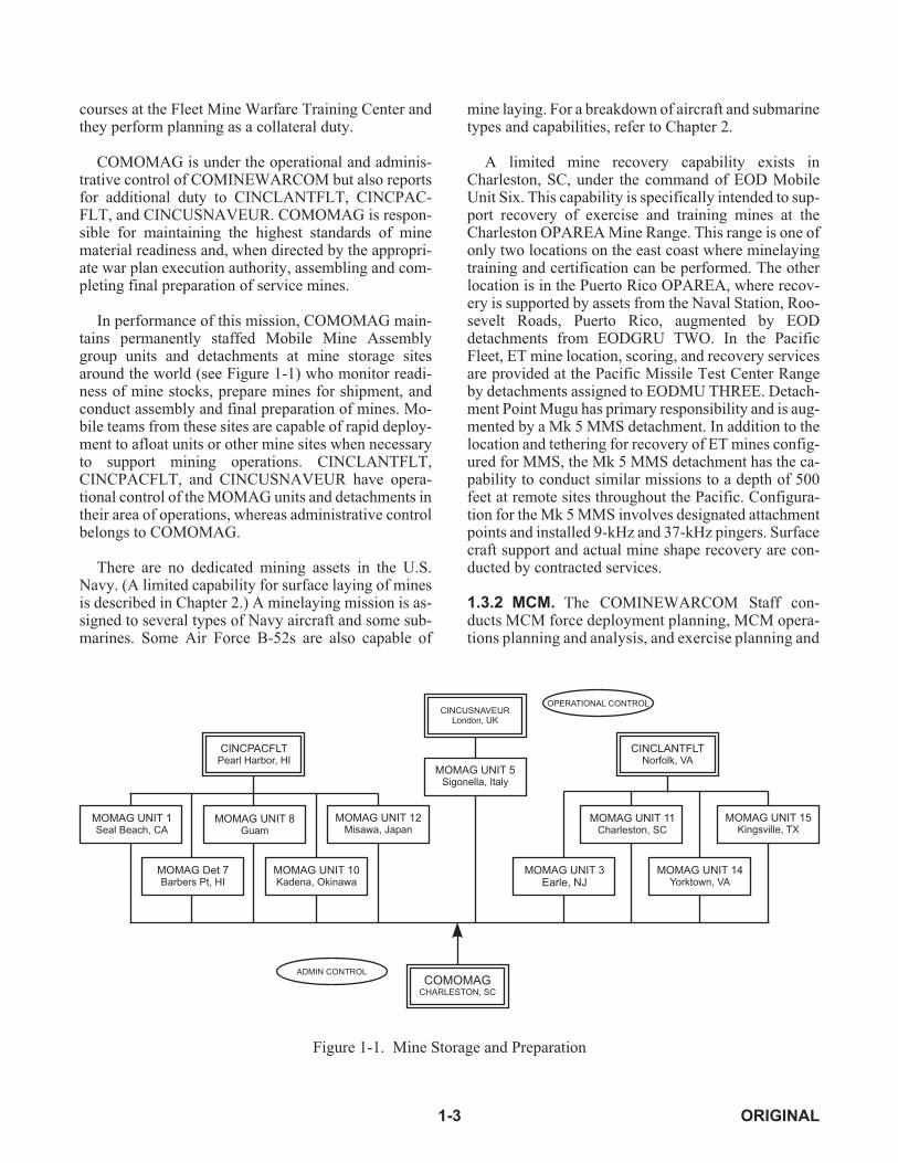
In performance of this mission, COMOMAG main-tains permanently staffed Mobile Mine Assemblygroup units and detachments at mine storage sitesaround the world (see Figure 1-1) who monitor readi-ness of mine stocks, prepare mines for shipment, andconduct assembly and final preparation of mines. Mo-bile teams from these sites are capable of rapid deploy-ment to afloat units or other mine sites when necessaryto support mining operations. CINCLANTFLT,CINCPACFLT, and CINCUSNAVEUR have opera-tional control of the MOMAG units and detachments intheir area of operations, whereas administrative controlbelongs to COMOMAG.
There are no dedicated mining assets in the U.S.Navy. (A limited capability for surface laying of minesis described in Chapter 2.) A minelaying mission is as-signed to several types of Navy aircraft and some sub-marines. Some Air Force B-52s are also capable of
mine laying. For a breakdown of aircraft and submarinetypes and capabilities, refer to Chapter 2.
A limited mine recovery capability exists inCharleston, SC, under the command of EOD MobileUnit Six. This capability is specifically intended to sup-port recovery of exercise and training mines at theCharleston OPAREA Mine Range. This range is one ofonly two locations on the east coast where minelayingtraining and certification can be performed. The otherlocation is in the Puerto Rico OPAREA, where recov-ery is supported by assets from the Naval Station, Roo-sevelt Roads, Puerto Rico, augmented by EODdetachments from EODGRU TWO. In the PacificFleet, ET mine location, scoring, and recovery servicesare provided at the Pacific Missile Test Center Rangeby detachments assigned to EODMU THREE. Detach-ment Point Mugu has primary responsibility and is aug-mented by a Mk 5 MMS detachment. In addition to thelocation and tethering for recovery of ET mines config-ured for MMS, the Mk 5 MMS detachment has the ca-pability to conduct similar missions to a depth of 500feet at remote sites throughout the Pacific. Configura-tion for the Mk 5 MMS involves designated attachmentpoints and installed 9-kHz and 37-kHz pingers. Surfacecraft support and actual mine shape recovery are con-ducted by contracted services.
1.3.2 MCM. The COMINEWARCOM Staff con-ducts MCM force deployment planning, MCM opera-tions planning and analysis, and exercise planning and
1-3 ORIGINAL
CINCUSNAVEURLondon, UK
OPERATIONAL CONTROL
ADMIN CONTROL
MOMAG UNIT 12Misawa, Japan
MOMAG UNIT 11Charleston, SC
MOMAG UNIT 3Earle, NJ
COMOMAGCHARLESTON, SC
MOMAG UNIT 14Yorktown, VA
MOMAG UNIT 15Kingsville, TX
MOMAG UNIT 5Sigonella, Italy
CINCLANTFLTNorfolk, VA
MOMAG UNIT 8Guam
MOMAG UNIT 1Seal Beach, CA
CINCPACFLTPearl Harbor, HI
MOMAG Det 7Barbers Pt, HI
MOMAG UNIT 10Kadena, Okinawa
Figure 1-1. Mine Storage and Preparation
analysis. Staff intelligence personnel monitor the col-lection and analysis of intelligence on MEW capabili-ties throughout the world. Staff requirements personnelconduct liaison with type and operational commandersand with supporting organizations to determine un-filled operational needs and prepare mission need state-ments for unfilled requirements.
Operations personnel, in addition to planning opera-tions and exercises, review tactics and doctrine seekingto maximize integration of MIW forces into fleet opera-tions and maximize the effectiveness of MCM forces.
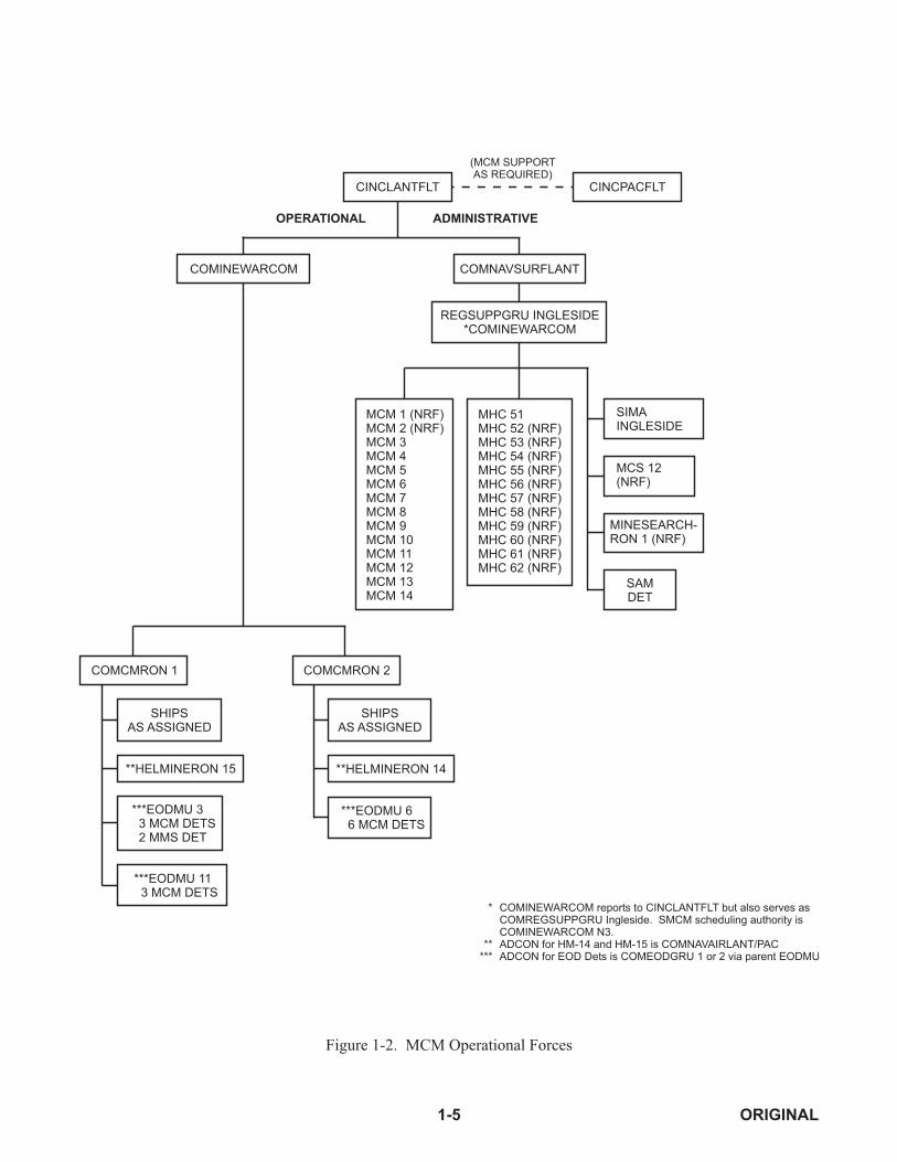
As shown in Figure 1-2, Commander, Regional Sup-port Group Ingleside (additional duty of COMINE-WARCOM) is assigned administrative control oversurface MCM forces, including SIMA Ingleside.COMNAVSURFLANT is the type commander for sur-face MCM units, performing all type commander du-ties except for scheduling. The COMINEWARCOMStaff Operations Officer maintains scheduling author-ity of MCM forces.
COMCMRON ONE is responsible for planning andexecuting MCM exercises and operations as directed byCOMINEWARCOM. COMCMRON ONE focuses onMCM planning for the Pacific theater, although opera-tional assignment may be to any theater. COMCMRONONE is assigned operational control of MCM 1 Classand MHC 51 Class ships as necessary for intermediate oradvanced training and for participation in exercises orreal world operations. COMCMRON ONE also has op-erational control over Helicopter MCM Squadron Fif-teen (HM-15) and west coast EODMCM detachments(see Figure 1-2). Administrative control of HM-15 is as-signed to COMNAVAIRPAC. Administrative controlof west coast EODMCM detachments is assigned to theparent EOD Mobile Unit under COMEODGRU ONE.
COMCMRON TWO has the same responsibilitiesas COMCMRON ONE with a focus on the Atlantic andMediterranean theaters and is assigned operationalcontrol of HM-14, east coast EODMCM detachments,and MCM or MHC ships as necessary. Administrativecontrol of HM-14 is assigned to COMNAVAIRLANT,and administrative control of EODMCM detachmentsremains with their parent EOD Mobile Unit underCOMEODGRU TWO.
COMINEWARCOM, under COMNAVSURF-LANT, has administrative control over all MHC andMCM class ships and operational control over allMCM and MHC class ships that have not been assignedto one of the other squadrons.
MCM assets that have completed all basic phasetraining requirements may be assigned to COMSEC-ONDFLT or COMTHIRDFLT for participation in fleetlevel exercises or support of the numbered fleet com-mander’s operational requirements. This assignmentwill usually be made as an integrated task unit includ-ing an MCM squadron commander.
EOD is a critical aspect of modern MCM forces.EODMCM detachments are specially trained andequipped with nonmagnetic, low-acoustic signatureequipment that permits them to approach influencemines safely and perform identification, destruction, orrender-safe and recovery operations.
In the Atlantic Fleet, six EOD detachments areassigned to EODMU SIX, and two MCM detachmentsare assigned to EODMU EIGHT. Additionally, there isone EOD MMS detachment with a mine recovery mis-sion (Mk 5) assigned to EODMU SIX. Administra-tive/operational control of the EODMCM detachmentsat EODMU EIGHT remain with EODMU EIGHT, un-der COMEODGRU TWO (ADCON) and CINCUS-NAVEUR (OPCON). Other Atlantic Fleet EODMCMand EOD MMS detachments ADCON remain withtheir parent mobile units, and OPCON is assigned toCOMINEWARCOM. In the Pacific Fleet, two EOD-MCM detachments each are assigned to EODMUELEVEN and EODMU FIVE, and three EODMCMdetachments are assigned to EODMU THREE. Addi-tionally, there are two EOD MMS detachments (Mk 4 andMk 7) with MCM missions assigned to EODMU THREE.Administrative/operational control of the EODMCM de-tachments at EODMU FIVE remain with EODMU FIVE,under COMEODGRU ONE (ADCON) and CTF-76(OPCON). Other Pacific Fleet EODMCM and EOD MMSdetachments ADCON remain with their parent mobileunits and OPCON is assigned to COMINEWARCOM.
NSW forces are responsible for conducting MCM inthe VSW/SZ) regions in support of amphibious opera-tions. NSW forces are not routinely included within theMCM force chain of command. When an ATF is assem-bled, the NSW forces assigned to the CATF will includeSEAL teams capable of conducting the VSW/SZ MCMmission. SEAL teams maintain one platoon trained inconducting VSW/SZ MCM and capable of integratingwith other team members to execute the MCM mission.
The Commanders, MARDEZ Atlantic and Pacific areresponsible for MIW planning within the MARDEZ.MARDEZ sector and subsector commanders participatein preparation of MIW plans and monitor MCM opera-tions but do not have permanently assigned MIW assets.In wartime, COMSECONDFLT or COMTHIRDFLT
ORIGINAL 1-4
1-5 ORIGINAL
REGSUPPGRU INGLESIDE*COMINEWARCOM
COMNAVSURFLANT
MCM 1 (NRF)MCM 2 (NRF)MCM 3MCM 4MCM 5MCM 6MCM 7MCM 8MCM 9MCM 10MCM 11MCM 12MCM 13MCM 14
MHC 51MHC 52 (NRF)MHC 53 (NRF)MHC 54 (NRF)MHC 55 (NRF)MHC 56 (NRF)MHC 57 (NRF)MHC 58 (NRF)MHC 59 (NRF)MHC 60 (NRF)MHC 61 (NRF)MHC 62 (NRF)
SIMAINGLESIDE
MCS 12(NRF)
MINESEARCH-RON 1 (NRF)
SAMDET
CINCLANTFLT CINCPACFLT
(MCM SUPPORTAS REQUIRED)
COMINEWARCOM
COMCMRON 1 COMCMRON 2
SHIPSAS ASSIGNED
**HELMINERON 15
***EODMU 33 MCM DETS2 MMS DET
***EODMU 113 MCM DETS
***EODMU 66 MCM DETS
**HELMINERON 14
*
*****
COMINEWARCOM reports to CINCLANTFLT but also serves asCOMREGSUPPGRU Ingleside. SMCM scheduling authority isCOMINEWARCOM N3.ADCON for HM-14 and HM-15 is COMNAVAIRLANT/PACADCON for EOD Dets is COMEODGRU 1 or 2 via parent EODMU
SHIPSAS ASSIGNED
OPERATIONAL ADMINISTRATIVE
Figure 1-2. MCM Operational Forces
will delegate control of mining or MCM forces as nec-essary (and if available) to support the MARDEZcommanders.
1.3.3 Naval Reserve Forces. NRFs have playedan important role in MIW for many years. From theearly 1970s until the end of the 1980s, the majority ofthe SMCM force was assigned to the NRF. Due largelyto the role of mines in the Iran-Iraq War and OperationEarnest Will, as the MCM 1 Class ships replacedMSOs, they have remained in the active force. TheMHC 51 Class was designated to be commissioned inthe active force and transfer after 1 year to NRF statusto maintain an active-reserve mix. As of October 1994,the planned active-reserve mix of ships is 10 active to 4NRF MCM 1 Class ships and 1 active to 11 NRF MHC51 Class ships. Additionally, the MCS 12 will be as-signed to NRF status when conversion is complete.
The Naval Reserve also plays a role in the AMCMand EODMCM force. HM-14 and HM-15 each have areserve component of pilots and maintenance person-nel. Of the 12 aircraft assigned to each squadron, 6 be-long to the active squadron and 6 belong to the NRForganization. NRF EOD forces are composed of fourreserve units: EODMU TEN and EODMU TWELVEunder COMEODGRU TWO, and EODMU SEVENand EODMU SEVENTEEN under COMEODGRUONE. Each reserve unit trains and provides administra-tive support for three different types of detachment:OCDs are fully qualified in diving and demolition pro-cedures and are trained to locate, identify, and disposeof sea mines. ASDs use side-scan sonar systems to lo-cate minelike objects underwater. MCDs provide fullymobile communications capability in support of fleetoperations and exercises.
Another Naval Reserve program that supports MIWis the MSS and MSU. The MSS is an administrativestaff consisting of reservists on active duty (TARs) whomanage the staffing and training of MSUs. Along withother missions, an MSU trains in the operation ofside-scan sonar systems for mine hunting alongQ-routes or in harbor approaches where small craft canoperate. The craft used by these units may be Navy as-sets or commercial assets contracted for the purpose.This program replaced the COOP in 1994.
Naval Reserve units are also used to augment thecommand and control structure for MIW. COMINE-WARCOM has a reserve staff detachment available foraugmentation when needed, and NRF Mine DivisionStaffs have supported Mine Squadron Staffs. As thearmed forces are reduced in size, the NRF staff struc-ture is also expected to be reduced.
1.4 NATO/ALLIED COALITION ANDCOOPERATION
In almost any foreseeable MIW operation of signifi-cance, U.S. Navy MIW forces can expect to be operatingside by side with NATO and/or other Allied forces. Suchcoalition type operations could even include MCMforces of the former Soviet Union or Warsaw Pact.
1.4.1 Operations. Each of the NATO/Allied MIWservices brings its own strengths into combined opera-tions. Whenever multinational forces operate together,many different types of MIW vessels with varying sys-tems and degrees of readiness will be encountered.These may include sweepers, surface drones, hunters,divers, AMCM helicopters, remote underwater vehi-cles, hull-mounted and variable depth sonars, side-scansonars, underwater vehicles with ahead-looking sonars,and utility helicopters. (For a brief description ofNATO/Allied MCM assets, see paragraph 3.7.1.) If theoperation is being conducted as a NATO operation,NATO doctrine, procedures, command structure, andcommunications techniques will be used. In situationssuch as the 1987-88 Operation Earnest Will in the PersianGulf, several nations’ MCM forces (all of whom weremembers of NATO) were operating in the same area witha common mission, but not under a combined commandstructure. The forces used NATO procedures and doctrineand resolved potential conflicts by close communicationsbetween all nations concerned. Future multinationalMCM operations may include Partnership for Peace na-vies or Allies from the Pacific theater who are not mem-bers of NATO. MCM doctrine is currently beingdeveloped in NATO that takes into account operationswith almost any free world navy. As more exercises andreal world operations that include multinational forces oc-cur, fewer interoperability problems can be expected.
1.4.2 Non-NATO Operations. COMINEWARCOMhas made recommendations to the Navy InternationalPrograms Office (IPO-10) on how to sanitize the NWP3-15 (formerly NWP 27) series of MIW publications forrelease to foreign nations. The sanitization instructionsare written at three different levels: NATO plus Japanand Australia, Allied nations, and Third World nations.NAVIPO does not automatically provide these sanitizedpublications to foreign navies. A foreign governmentmust ask for the publications and must pay for them.Therefore, a battle group commander who wishes to uti-lize these sanitized NWP 3-15 series publications to con-duct Mine Warfare operations with a foreign navy mustensure that the foreign navy requests the publicationsfrom NAVIPO (IPO 10) or that the Battle Group Com-mander makes the request. In many cases, the actualsanitization has not been done by NAVIPO. In that
ORIGINAL 1-6
case, the battle group commander may receive in-struction from NAVIPO on how to sanitize the spe-cific publications.
1.4.3 Doctrine. NATO MIW doctrine is delineatedin ATP 6 and ATP 24. This is the doctrine that all NATOnavies, including the U.S. Navy, will follow duringNATO operations or exercises. Almost every NATO na-tion has a national annex to ATP 24 that may contain vari-ations in the standard doctrine or specifics on nationalsystems not released to all nations. U.S. national doctrineis very similar in many ways to the NATO doctrine. Theonly variations in doctrine may stem from differences inforce capabilities (e.g., availability of AMCM forces) ordifferent geographically driven missions. The NWP 3-15series is the primary doctrine for U.S. Navy MCM andmining forces. The U.S. MCM Commander must be pre-pared to operate exclusively within NATO doctrine andprocedures and to explain to NATO counterparts whenU.S. Navy forces will deviate or operate apart from theNATO doctrine because of national concerns. This sameprocedure is currently followed by other NATO navieswhen national concerns become paramount.
1.4.4 Support Organizations. Within the NATOorganization there are working groups, planninggroups, IEGs, PGs, and AGs. Written agreementswhich foster cooperative development of MIW tech-niques, tactics, and systems focus the combined knowl-edge of the participants on the shortcomings of existingMine Warfare systems and capabilities.
The bilateral (Belgium/The Netherlands) Mine War-fare School (Eguermin) at Oostende, Belgium, func-tions as a center for NATO MIW training. Eguermin isused by U.S. forces as well and is closely linked withU.S. MIW training facilities.
The MWWP was established to initiate, develop,and process proposals for military standardization, in-cluding tactics, tactical instructions, and procedures inthe field of MIW. The MWWP brings Mine Warfareparticipants together annually to discuss issues of com-mon concern in mining, MCM, training, equipment,support, command, control, and communications. Thishas been a key component of the successes achieved byNATO MIW forces, although each may have beenworking under specific national directives. Currently,the MWWP is organized with three panels: opera-tional/tactical, technical, and exercise evaluation.
DEAs generally are bilateral diplomatic toolswhereby agreement is made to exchange certain data formutual military purposes. Unlike general agreements,the DEAs are negotiated between countries or groups of
countries for specific types of information. There arefew general DEAs in existence. Frequently, newly ob-tained data and information can be exchanged rapidlywhen a DEA is in place.
1.5 INTERNATIONAL LAW ASPECTS OFMINE WARFARE
1.5.1 Hague Convention. The Hague Convention(VIII) of 1907 probably had more of a legal impact onMIW than any other forum. The attendees at this con-vention placed international restrictions on the use ofdrifting mines, established various guidelines that af-fected automatic contact mines, and set forth require-ments for the incorporation of sterilization and/orself-destruct features in mines. The following specificprovisions were laid down by this Hague Convention:
1. Armed, unanchored mines must have a maxi-mum life of 1 hour.
2. Armed, anchored mines must become unarmedif they break free from their moorings.
3. Mines must be designed to become harmlessshould they miss their target.
4. It is illegal to mine solely against commercialshipping.
5. Neutral nations are not to be interfered with, andthe safe transit of neutral shipping must beensured.
6. Mines must be removed by the planting force atthe conclusion of hostilities.
The specific international laws set forth during theHague Convention remain in effect today; however,they have not been always been adhered to by all na-tions, and world events have seen major deviationsfrom these principles. Although the United States didnot ratify the Hague Convention, we have alwaysabided by its restrictions and principles.
1.5.2 Other Legal Aspects. Both offensive anddefensive mining operations are considered to be actsof war. The intent of these mining operations is to in-flict damage to or restrict the transit of enemy shipping.Protective mining conducted within a nation’s own wa-ters is not considered an act of war as long as the neces-sary notifications to shipping are made through theappropriate channels.
The Seabed Arms Control Treaty of 1972 prohibitedthe use of mass destruction weapons that are attached to
1-7 ORIGINAL
the ocean floor beyond a 12-mile coastal zone. Thistreaty applies to the use of nuclear warheads in eitherbottom or moored mines since they are designed to re-main in place after they are armed. U.S. policy on theemployment of naval mines is addressed in chapter 9 ofNWP 1-14 (formerly NWP 9), and in chapter 1 ofNWP 3-15.5 (formerly NWP 27-4).
1.6 MINE WARFARE/POLITICAL INTERFACE(INTELLIGENCE AND WARNINGS)
History is well endowed with peacetime, wartime,and low-intensity conflict MIW incidents ranging fromthreat alone to large-scale mining campaigns. Appen-dix C provides a synopsis of MIW history to illustratethe place of MIW in overall military-politicalperspective.
The intelligence data available plays a crucial role indetermining the effectiveness of mining and MCMplanning and operations. Without knowledge of poten-tial mining events or the MCM capability of a potentialenemy, mining and MCM planners are likely to prepareineffective plans that may place delivery assets, MCMassets, or transiting commercial and naval ships at risk.Mining and MCM planning are based on a significantnumber of assumptions even in the best of situations;therefore every effort should be made to reduce theseassumptions and protect the expenditure of critical re-sources. All information and data requested by a plan-ning staff should be made available to the maximumextent possible and as quickly as possible.
1.6.1 Threat. To the miner, knowledge of the threatmeans knowing what the minelayer must face in perform-ing his mission and knowing what MCM forces may beused to counter the minefield. To the MCM planner,knowledge of the threat means knowing what types ofmines were available to or used by the layer, as well as theavailable operating selections of those mines. U.S. MCMforces have no defensive ability against other threats.
The MCM commander must be able to brief militaryand political authorities on the MIW threat so that theycan balance the final risks and goals against the realizationof that threat. No threat can be discounted as insignificantto the MCM force or the transiting assets. Even primitiveweapons can bring havoc and mission- abort situations tomodern forces. The threat is always the explosive capabil-ity of the weapon without regard for the packaging.
1.6.2 Movement of Forces. An essential elementof intelligence information in MIW is movement offorces. Consider the miner: movement of certain of hisforces may indicate pending or imminent deployment of
mines. If mines and the laying forces are not collocated,the miner must plan the logistic support and timing toget the mines to the minelayer, and this time can be ex-ploited by the opposition if movement is detected.
MCM forces are typically slow transiters who re-quire significant support to remain at sea. They are notcommonly found with a battle group unless an MCMaction is planned. Therefore, the movement of MCMforces may be an indicator of a planned amphibiouslanding or SLOC choke point penetration.
Political will must be exercised on either side inthese cases. Forward deployment of MCM forces maybe sufficient to determine or complicate and thwart amining plan. Early movement by miners may be suffi-cient to permit national authorities to justify offensiveMCM against vessels at sea or shore facilities.
1.6.3 Delay Arming. Delay arming features allowthe miner to conduct operations and leave the area priorto the arming of weapons. This can permit actions to beconducted prior to the acknowledged beginning of hos-tilities or operations. The threat may exist long before itis recognized by conventional forces because the minerdetermines when the threat becomes valid. Addi-tionally, arming delays can and will complicate opera-tions for the MCM forces because environmentalfactors and operational factors can then require arecommitment of critical assets to an area otherwise be-lieved to be safe. Delay arming cannot be discounted inany operational scenario until proof exists that no suchfeatures were used by the opposing force.
Recent history has emphasized that the threat may beoutside of international law or convention, hence thesaying “ a mine in the water has no loyalty.”
1.7 MINE WARFARE INTERFACE WITHOTHER WARFARE SPECIALTIES
1.7.1 Mine Warfare Coordinator. To improvethe interface between MIW and other warfare special-ties, a MIWC was added to the CWC’s organization.Following are the roles of the MIWC:
1. To act as the single point of contact for MIW
2. To provide recommendations to the CWC andother warfare commanders and coordinators
3. To provide guidance on how MIW operations fitinto theater operations of the fleet commander.
The MIWC shall also perform the following tasks:
ORIGINAL 1-8
1. Make recommendations to assist in establishingforce disposition in the presence of a mine threat
2. Coordinate requests for all nonorganic miningand MCM support
3. Evaluate the implications of enemy mine war-fare operations and recommend appropriateMCM operations
4. Coordinate with the ASWC on all defensiveminefield planning matters
5. Coordinate the employment of tactical air assetsin mining with the STWC
6. Ensure that mining operations are conducted inaccordance with international law
7. Designate MDAs
8. Maintain the status of all force MIW capabilities
9. Coordinate obtaining oceanographic support formining operations.
The MIWC maintains an OPTASK MIW Supple-ment to communicate general procedures and instruc-tions to other forces inside and outside the CWCorganization as necessary.
1.7.2 Strike Warfare. STW capable aircraft are akey element in many mining plans. The MIWC pro-vides recommendations to the CWC for employment ofstrike assets to conduct mining that will support CWCobjectives. If approved, the minelaying planning andexecution are then carried out by the STWC and StrikeOperations Department on board the CV.
STW assets are also employed in conducting offensiveMCM. Reconnaissance conducted by tactical aircraft mayidentify movement of mine assets or minelayers, indicat-ing mining is imminent. The MIWC monitors intelligencedata and provides offensive MCM targeting recommen-dations to the STW and CWC early in the conflict.
1.7.3 Special Operations. Special operationsforces are involved in both offensive and defensiveMCM. In certain situations, special operations forcesmay be chosen to conduct raids to cripple or destroy op-position force mine storage sites and mine stocks. Theirability to conduct small-scale raids with accuracy andlimited collateral damage may be preferred in somecases over tactical air strikes or TLAM strikes. In thedefensive MCM role, NSW forces conduct beach recon-
naissance in advance of an amphibious landing to de-termine whether a mine threat is present. When minesare encountered, the NSW force is responsible for mineclearance in the very shallow water and surf zones.NSW forces work together with EODMCM, AMCM,and SMCM forces to develop coordinated tactics forconducting MCM in support of amphibious operations.
1.7.4 Surface Warfare. MCM forces interface withASUW forces in several ways. In situations where nolarge deck MCM command ship is available, a surfacecombatant may serve as the flagship for the MCM com-mander and provide support to surface MCMVs. Largerships (e.g. CGs) are well equipped as command plat-forms and can accommodate the MCM Commander’sstaff. ASUW forces can provide protection from variousthreats to MCM forces, as well as some logistic support.They also may be tasked to provide ASUW helicoptersto transport EOD forces and conduct spotting for minescut by mechanical sweep operations or drifting mines.MCM forces conduct reconnaissance of ASUW ship op-erating areas when mining is suspected and, if necessary,clear operating areas for ASUW ships to conduct patroloperations or fire support operations.
1.7.5 Antisubmarine Warfare. ASW forces mayemploy protective minefields (laid by air assets) as barri-ers to assist in controlling the submarine threat. The CAP-TOR mine can be used alone or in conjunction with othermines in this role. ASW forces will support the MCMforce by maintaining reconnaissance in their area of oper-ations for minelaying assets or the existence of mine-fields. Some ASW sonars can also be employed for minedetection and avoidance. They permit the ASW ship tooperate with an increased degree of safety in waters wherethe mine threat has not been determined, allowing the shipto detect moored mines and avoid transiting through amined area. The ASW ship’s helicopter can supportMCM forces by providing transportation to EODMCMforces and conducting aerial surveillance.
1.7.6 Antiair Warfare. The interface between MIWforces and AAW forces is limited to the protection roleAAW ships and aircraft perform. MCM forces, both sur-face and air, are not equipped for self-defense. If anyhostile air threat exists, it is necessary for AAW forces tobe assigned to counter that threat and permit MCMforces to operate. Considering the small size of theMCM force, even the loss of one ship or helicopter canbe critical to completion of the MCM mission.
1.7.7 Amphibious Warfare. MCM forces havehistorically operated in close support of amphibious op-erations when conducting an opposed landing. The mineis one of the cheapest weapons that can be employed
1-9 ORIGINAL
against an invading sea force, and the presence ofmines without a sufficient capability to counter themcan result in significant losses to the AMW force orcancellation of landing operations.
Early, detailed requirements should be provided bythe supported commander for amphibious operations(e.g., CATF) to the MCM Commander to facilitateplanning. MCM considerations include the size of theAOA in comparison to the available MCM assets, slowMCM ship transit times to the AOA, the rate of MCMoperations required to meet established deadlines, andrequirements to protect MCM operations against hos-tile threats (including the use of OPSEC and OPDEC).Enemy observation of friendly MCM operations maycompromise tactical surprise. In addition to conven-tional MCM forces, NSW forces are employed in am-phibious operations to locate, destroy, and/or neutralizeenemy barriers, obstacles, or minefields placed in or onthe shallow water approaches to the landing beaches.
Large-deck, aviation-capable amphibious ships arefrequently assigned to embark and support MCM forcesof all types. Although Marine forces are displaced, theLPH and LPD have both been used extensively as MCMsupport ships, with the MCM commander, AMCM heli-copters, and EODMCM detachments embarked and pro-viding logistic support to surface MCM vessels.
During MCM operations in support of amphibiousoperations the CLF will also supply assets to be used inthe shallow water/surf zone MCM effort, such as com-bat engineers, tank plows, bulldozers, etc.
1.7.8 Maritime Interdiction Operations/LawEnforcement Operations. MIO/LEO forces arelikely targets for mining and should remain alert for in-dications of mine laying. The use of passive MCM ex-plained in Chapter 4 should be reviewed and employedwhere appropriate. When inspecting transiting mer-chants, it is important to note any cargo and handling orpacking equipment that might have been used in trans-porting or laying mines. If mining has occurred or is ex-pected, MIO/LEO forces should be supported by MCMforces to establish safe operating areas, anchorages,and transit lanes.
1.7.9 Salvage Forces. Salvage forces not engagedin salvage operations may be called on to support MCMforces by providing an operating platform forEODMCM divers. Any salvage vessels that have an in-stalled recompression chamber will be considered forsupport to EOD divers who may require emergencyrecompression. If an MCS is present and has an installedrecompression chamber, it may also be used to supportsalvage forces. MCM forces are frequently called on to
assist in initial location of aircraft, boats, or other assetsthat have been lost so that salvage forces can conductrecovery operations. The minehunting sonars on MCM1 and MHC 51 Class ships and the side-scan sonar usedby AMCM are excellent for locating bottom objects,and the AN/SLQ-48 MNS can be used to make positiveidentification on objects much deeper than divers canoperate.
1.7.10 Command and Control Warfare. C2Wis essentially an employer of MIW forces. The threat ofmining or the ready availability of MCM forces can beused to influence an enemy’s command and control.Placing a CV into position has significant impact on theenemy’s decision-making because of the STW capabil-ity resident within the CV, including mining. In the samemanner, deployment of MCM forces or prepositioningof MCM forces in a theater reduces the potential impactof opposition mining and may result in a decision not tocommit a hostile mining action. Additionally, C2W mayplay a part in the defense of minelaying forces by provid-ing both early warning against opposition forces andcover by jamming air defenses. For the MCM mission,the primary interface is via the information flow fromC2W sensors, which might indicate mining in progress.This information is normally channeled through the in-telligence community for analysis and then passed to thetheater or battle group commander as an indicator of theneed for MCM effort.
1.7.11 Fleet Exercises. MCM forces are integratedwith battle group training exercises whenever possible.For inport training exercises, participation may be limitedto MCM squadron staff members, either on-scene or froma remote location. During fleet exercises, MCM forcesmay participate in the scenario by transiting to the exer-cise operation area or by establishing a scripted geo-graphic area near the MCMV homeport of Ingleside, TX.The MCM staff can conduct exercises in this area andtransmit information with coordinates converted to matchthe geography of the fleet exercise area. Since MCM op-erations frequently occur out of sight of the battle group,this type of participation saves fuel and transit time with-out sacrificing significant aspects of the interface betweenthe MCM and the battle group.
1.8 MINE WARFARE/JOINT INTERFACE
1.8.1 Army-Navy. The Army is responsible forconducting most mine development, minefield planning,and MCM on land, although the Marines share some re-sponsibility. The Navy responsibility ends at the land-ward limit of the craft landing zone along sea shores, butextends inland where waters are navigable from the sea.Where navigation is no longer possible by seagoingvessels, Navy responsibility ends. However, when a
ORIGINAL 1-10
mining situation exists, the Joint Force Commanderwill be primarily concerned with capability, not respon-sibility. If Navy assets are capable of conducting MCMin a waterway where Army craft need to navigate, it islikely they will be directed to clear the mines. Theriverine MIW operations in Vietnam are a primeexample.
The Army has a tremendous amount of material thathas to be moved to support overseas operations such asOperation Desert Storm. The majority of this materialmust be moved by sealift ships belonging or under con-tract to MSC. To support the rapid buildup of forcesnormally desired in an overseas conflict, the loading,transit, and unloading of these ships must follow a tightschedule. A mining threat either in CONUS, atchokepoints along the SLOCs, or at the offload port candelay or completely halt the movement of material.U.S. Navy MCM forces (and MCM forces from NATOor Allied nations if involved) will be tasked by the JointForce Commander to clear channels and anchoragesand to maintain them to permit the free flow of traffic.EODMCM forces may also be tasked to clear and assistin maintaining safe harbors for off-loading of shipping.
1.8.2 Air Force-Navy. The Air Force plays two im-portant roles in supporting MIW forces (in addition topotentially supporting offensive MCM). The first roleplayed by Air Force assets is the laying of mines byB-52 aircraft. The B-52 can carry the largest mine loadof any U.S. aircraft and can deliver mines at long dis-tances from CONUS or other bases. B-52s may play acritical role in accomplishing mining plans directed forexecution by joint commands.
The second is the Air Mobility Command’s supportof deployment of AMCM and EODMCM forces and thecontinuing delivery of critical repair parts via AMC air-craft. Even in a situation where all MCM forces deployby surface lift, rapid delivery of critical repair parts iscrucial to maintain MCM force readiness for operations.
1.8.3 Marine Corps-Navy. The interface of MarineCorps assets and MCM forces is to some extent the sameas that described for its interface with the Army. Rapiddeployment of USMC forces other than those alreadyembarked on amphibious shipping is accomplished byairlift of the personnel to a location where they can beunited with equipment stored on MPSRON ships. In thesame manner as MSC shipping carrying Army material,the MPSRON ships must be provided clear channels,safe anchorages, and harbors in which to unload theirmaterial. In some situations the MPSRON ships will jointhe amphibious ships and be supported by MCM forcesto establish a landing beach and move assets ashore.
1.8.4 Coast Guard-Navy. During peacetime, theCoast Guard is part of the Department of Transporta-tion and yet maintains a significant degree of interfacewith the Navy through the MARDEZ organization. TheCommanders, MARDEZ Atlantic and Pacific are CoastGuard Admirals, and there are Coast Guard officers onmany Navy staffs to maintain the MARDEZ structureand interface with the Navy. These officers usually aregraduates of MIW training courses. As the MARDEZmission expands into deployable port control andcoastal shipping management and control, the interfacewith Navy MCM commands will increase.
Coast Guard assets are frequently involved in exer-cises where mining and MCM are included. Liaisonwith the local Coast Guard captain of the port is neces-sary for loading or unloading exercise mines at CoastGuard bases or commercial docks. Establishment of ex-ercise minefields in areas that are not regular NavyOPAREAs requires coordination with the local CoastGuard command.
In the past, when the mission to conduct route sur-veys in all U.S. ports was active, a Coast Guard officerwas assigned to the COMINEWARCOM staff to facili-tate cooperation between Coast Guard assets and Navysurvey teams. Coast Guard buoy tenders have been andmay be used to conduct survey operations in a numberof scenarios using portable side-scan sonar equipment.They could also be used again if the route survey mis-sion were to be reactivated.
In wartime, when the Coast Guard operates underthe Department of the Navy, route survey and supportof MCM forces conducting operations in CONUS willlikely be supported to a major degree by Coast Guardassets.
1.9 RULES OF ENGAGEMENT
ROE are directive guidance that authorize and delin-eate the circumstances and limitations on the use offorce. ROE are generally mission-oriented and actionspecific. ROE promulgated by the Theater Commanderare based on guidance provided by the NCA throughthe Chairman of the Joint Chiefs of Staff. This guidancereflects political, legal, operational, and diplomatic fac-tors that may restrict combat operations. ROE are re-quired throughout the operational continuum to ensurecompliance with the laws of war and NCA guidance.Combatant commander pre- and post-hostility ROEand OPLAN ROE should address authority to place ob-stacles and mines, including the FASCAM. FollowingNCA release of these elements for operations, ROEshould address their employment by U.S. forces and the
1-11 ORIGINAL
prevention, denial, or countering of their employmentby the enemy.
1.9.1 Reconnaissance. Reconnaissance operationsto identify potential mine storage sites, minelayer move-ments, and restriction of traffic within national waterspresent circumstances that require special ROE. Forunits conducting reconnaissance in international wa-ters, ROE will define the permissible conduct of theunit upon encountering forces of a hostile or neutral na-tion. The execution of MCM reconnaissance operationsmay require the MCM force to operate in proximity toor inside an adversary’s territorial waters. ROE will beused to specify the permissible conduct of both theMCM force and protective forces.
1.9.2 NATO/Allied Rules of Engagement Inter-face. When control of a U.S. mining or MCM force orasset is assigned to a NATO commander, it must con-form to ROE established by the NATO command struc-ture. However, there may be occasions when U.S.forces will operate with or in support of NATO orAllied country forces, but control will not be passed to theNATO command. In this situation, the U.S. forces mustconform to U.S. ROE until otherwise directed by the U.S.command authority. Ideally, in a combined or coalition
force operation or exercise, all forces will operate underthe same ROE. When this is not the case, lines of com-munication must be established to permit the speedyresolution of issues that arise concerning conflict be-tween intended operations and ROE. The most impor-tant aspect of coalition operations is that the alliesunderstand U.S. ROE and that the U.S. commanderknows the ROE of other nations to employ all availableassets effectively.
1.9.3 Rules of Engagement Interface with War-fare Specialties Supporting Forces. As forcesfrom different branches of a command structure are as-signed to work in supporting roles without a change incontrolling authority, conflicts in ROE may arise.Mining or MCM forces may not be issued a relaxationof ROE that is approved for protecting C2W, specialoperations, or STW forces. Considerable confusion canresult when two units operating together have differentROE and are not aware of the situational differences.For this reason, it is important to keep supporting andsupported units advised of any changes in ROE. It maybe necessary to review and compare ROE when newforces are assigned and when missions are changed.
ORIGINAL 1-12
CHAPTER 2
Mining
2.1 ADVANTAGES AND DISADVANTAGESOF MINING OPERATIONS
2.1.1 Advantages. Mining operations are distin-guished from other naval operations in that mine-fields can inflict major, long-term damage on enemyshipping while allowing little or no chance for retal-iatory action against the minelaying forces. Mines liein wait for their target. Mining permits enemy ship-ping to be attacked without the necessity for a directconfrontation between the delivery vehicle and thetarget ship. Since the delivery vehicle does not haveto directly engage or even locate the target ship, thesmallest minelayer may indirectly destroy the mostpowerful capital ships, merchantmen, or enemy sub-marines. Minefields are also unique in that they pro-vide the laying forces with the possibility of settingup a preemptive defense in which the aggressor musttake full responsibility for any casualties that itsuffers.
The mine may also offer the advantage of covertnessand surprise, with the first indication of its presence be-ing a detonation. Even if it is not covert, mining will of-fer the advantage of concealment because a properlyplanted mine provides no visible warning of danger andits exact location is undetermined. Moreover, an armedmine operates 24 hours a day. From the time the mine isarmed until it is countered or its useful life expires andit becomes sterilized, a mine will continuously threatenenemy ships with no need to retire for logistics supportor any other purpose.
Mines, when used in conjunction with other forces,can serve as a force multiplier. A well-laid minefieldcan be used to perform a variety of functions that wouldotherwise occupy patrol or other combat forces, thusfreeing those forces for use in other warfare operations.For example, mines can be used to reduce the numberof vessels that are required to execute an effective navalblockade.
Early offensive mining may disrupt an enemy’s warplans more effectively than any other naval weapon.Mining also offers numerous complementary actions,
such as the overloading and disruption of the enemy’stransport and logistics systems caused by the mine-field’s interruption of normal port activity. The funnel-ing of supplies, or the storing of large concentrations ofsupplies in a few ports, will cause those supplies to bemore susceptible to attack by other warfare forces.
One of the most widely recognized advantages ofmining, but perhaps the one most difficult to quantify,is the psychological effect that a minefield has. The en-emy’s perception of the danger that is posed by a mine-field has a large psychological impact on the forces thatmust transit through it. While this is a real factor and adefinite advantage that is unique to a mine, it must berecognized that the psychological threat is the threatperceived by the enemy, not by the minelayer, and thatthis perception may vary from nation to nation and cul-ture to culture.
The mine may also be the only weapon of navalwarfare that offers an apparent ability to alter geogra-phy. An area that has been mined or one that has beendeclared to have been mined must be avoided by transitingforces as if it were land.
Implicit in all these advantages is the fact that themine may be very effective if its use is only simulatedor threatened. That is, its actual detonation may not be asignificant factor in its effectiveness.
2.1.2 Disadvantages. The primary weakness of amine is that it is a passive weapon that must wait for atarget instead of seeking it out and attacking it, and oncelaid, a mine recognizes no friends. Unless proper precau-tions are maintained, a mine can threaten friendly as wellas enemy ships. Also, a mine is stationary once it hasbeen planted, which provides the enemy with an oppor-tunity to detect the minefield and then either avoid it orcounter it with MCM operations. Additionally, expo-sure to sea water for long periods of time can cause themine to become materially degraded through either bio-logical fouling and/or corrosion, and the temperature ofthe water can adversely affect the life of the mine’s bat-teries. Another environmentally related disadvantage
2-1 ORIGINAL
of mining is that there are water depth restrictions onwhere mines can be laid.
2.2 MINE CLASSIFICATION
Naval Mines are typically classified in three ways:
1. By their final position in the water
2. By their method of delivery
3. By their method of actuation.
2.2.1 Final Position in the Water. When classi-fied according to the position they assume in the waterafter they have been laid, mines fall into three primarycategories.
1. Bottom/ground mines
2. Moored mines
3. Drifting mines.
2.2.1.1 Bottom/Ground Mines. Bottom mines arenonbuoyant weapons. When planted, the mine case is incontact with the sea bed and it is held in place by its ownweight. In areas with a soft bottom, these mines may becompletely or partially embedded in the sea bed, inwhich case they would be referred to as buried mines. Amine case that is resting on the bottom and not buried isreferred to as a proud mine. Bottom mines are alsocalled ground mines.
The nonbuoyant case of a bottom mine allows for theuse of a much larger explosive charge than that of abuoyant mine case. This larger explosive charge pro-vides the mine with a larger damage distance and en-ables a single mine to cover a larger volume of water.However, bottom mines must be planted in waterdepths where the target ships will be damaged by theexplosion. The depth at which a specific bottom minecan be effective against a specific surface target is de-pendent upon the shock resistance of the target, as wellas the amount and type of explosive used in the mine. Ifthey are intended for use against a surface ship, bottommines are most effective in comparatively shallow wa-ters (<200 feet). If planted in very deep waters, a sur-face vessel may pass over the mine without actuating itsfiring mechanisms, or if the firing mechanism is actu-ated, the surface ship may pass by without suffering thedesired level of damage.
There are two special categories of bottom mines thatreact differently from other bottom mines when they are
initially laid, but they become standard bottom minesonce they have reached their final plant position:
1. A moving bottom mine is a mine that is designedto move itself along the bottom after it has beenplanted but before it arms.
2. A self-propelled mine is a mine that is fitted withpropulsion equipment, such as a torpedo, that isused to propel the mine case to its intended finalplant position. For example, a submarine couldfire a self-propelled mine from a standoff pointthat is outside of the intended minefield location,and the mine would then propel itself to the de-sired plant location.
2.2.1.2 Moored Mines. Moored mines have apositive-buoyant mine case that is moored at a presetdepth beneath the water’s surface. The mine case isheld in place above the sea bottom by means of a cableor chain that is attached to an anchor. Moored mines arefrequently, but not always, fitted with a self-destructdevice that will cause them to flood and sink if they areseparated from their anchor. A moored mine that hasbeen separated from its anchor and risen to the surfaceis called a floater. Floaters may continue to float untileither they are struck and detonated or they deterioratefrom their exposure to the seawater.
Moored mines are designed to be laid in deep water,and they are effective against both submarines and sur-face ships. The maximum water depth in which amoored mine can be laid is limited by the length of itsmooring cable, the weight of the cable, and the minecase crush depth. The explosive charge and firingmechanism of a moored mine are housed in the posi-tive-buoyant case. Because this mine case is buoyant,the amount of the explosive charge used in mooredmines is less than that found in a typical bottom mine,and the damage radius is also smaller.
A major disadvantage of moored mines is that the moor-ing cable can be cut with mechanical sweep gear. Whenthis occurs, the mine case floats to the surface and can beavoided or detonated without accomplishing its mission.Another disadvantage of moored mines is that they can beaffected by current and tidal variations that could cause themine case to dip below its intended depth and thereby re-duce its effectiveness against a surface target.
Despite their susceptibility to mechanical sweeping,moored mines play an important role in mining opera-tions. They can be moored so close to the surface thatthe smallest craft entering the minefield will be endan-gered. Additionally, mooring mines at different water
ORIGINAL 2-2
depths will add a vertical dimension to a minefield, ren-dering it hazardous to both surface ships and sub-merged submarines.
There are two special types of moored mines thatcontain propulsion systems that enable the mine case toquickly reach the intended target:
1. Homing/guided mines are propelled mooredmines that use guidance equipment to home ontoa target once the target has been detected.
2. A rising mine is a propelled or buoyant mooredmine that releases from its mooring and rises todetonate on contact with, or in proximity to, atarget. A rising mine does not incorporate ahoming device to guide it to the target, but itdoes contain logic circuitry that enables it to cal-culate where it expects the target to be.
2.2.1.3 Drifting Mines. Drifting mines have abuoyant mine case, but they do not have an anchor orany other device to maintain them in a fixed position.They are free to move with the waves, currents, andwind. Drifting mines may float at the water’s surface,or they may be kept at a set depth beneath the surface bya depth-controlling hydrostatic device. Drifting minesare classified differently from a moored mine that be-comes a floater, because a floater was designed to beheld in place by an anchor and a drifting mine was de-signed to float freely with the tides and currents.
A modified version of a drifting mine is a buoyantmine case that has a weight attached to it that is heavyenough to hold the mine case near the bottom, but notheavy enough to hold it in place. These mines areknown as creeping mines, because they are free to creepalong the bottom when affected by tidal currents.
The principal advantage of drifting mines is thattheir use is independent of the bottom depth. They canbe set to oscillate at or near a preset depth, which per-mits the mining of water that is too deep for bottom ormoored mines. The major drawback of drifting mines isthat they scatter and imperil friendly and neutral ship-ping. Consequently, drifters are usually, but not al-ways, fitted with devices designed to sink them after arelatively short life span. Because of their short lifespan, the most useful application of drifting mines hasbeen in tactical situations in which they are laid in thepath of an enemy force to cause a delay or diversiongiving friendly forces a tactical advantage.
2.2.2 Method of Delivery. When mines are classi-fied according to the method by which they are deliv-
ered, they again fall into three categories: aircraft-laidmines; submarine-laid mines; and surface-laid mines.
2.2.2.1 Aircraft Delivery. Aircraft are the mostsuitable vehicles for the majority of offensiveminelaying operations because they can penetrate areasdenied to surface ships and submarines. Air-deliveredmines are dropped from aircraft in the same manner as abomb, and in general, any aircraft that is equipped tocarry bombs can carry a similar load of mines of thesame weight class. These mines are specially config-ured for air delivery and they are designed so that theywill not crush or be damaged upon water entry.
There are a number of advantages associated with aer-ial mining operations. When compared to the other minedelivery platforms, aircraft have a fast reaction time andthey can respond quickly to a mining mission. They arealso the only delivery platform that can replenish an exist-ing minefield without being endangered from previouslylaid mines. Airplanes can also be used to mine en-emy-held inland waterways, and they can lay mines inshallow bodies of water, including rivers and harbors, thatcannot be transited by submarines or surface minelayers.
There are two major disadvantages associated withthe use of aircraft as minelaying vehicles. First, theweapon loads are relatively small unless large,cargo-carrying aircraft are used for mine delivery. Sec-ond, the mine positioning accuracy is lower with air-craft than with surface ship deliveries.
2.2.2.2 Submarine Delivery. Submarine-deliveredmines are normally used in covert offensive operations.These mines are specially configured so that they can belaunched from the torpedo tubes or mine belts of subma-rines. Submarines are effective minelayers because theycan penetrate areas that are too well protected by airand/or surface craft for other minelayers. The availabilityof mobile standoff mines enhances the submarine’sminelaying capability.
Submarine mine delivery is a covert operation, andwhen secrecy is paramount, the submarine is the pre-ferred minelaying vehicle.
When required by OPORD or specified by Combat-ant Commander, capable SSNs can be available andloaded with mines, but this requirement has to be antic-ipated in advance to be readily available. A disadvan-tage associated with submarine mine laying is that thereare limited numbers of submarines available, and they arefrequently already tasked for other missions when theneed for a mining mission is identified. Submarines havea limited mine-carrying capacity and a relatively slow
2-3 ORIGINAL
reaction time. In order for a submarine to conduct amining mission, it must first be recalled to a port whereit can offload torpedoes and onload mines.
2.2.2.3 Surface Delivery. The Mk 60 CAPTORmine is the only U.S. mine that can be surface laid. It re-quires a surface ship with a crane or boom that can dropthe mine from a height of at least 30 feet above the wa-ter using a modified aircraft weapons rack. All otherU.S. mines would require extensive engineering modi-fications to be surface laid. Surface mine delivery re-quires control of the sea area, and it is thereforeconsidered to be a suitable delivery method for defen-sive minefields only.
Surface ships offer two major mine delivery advantages.First, they are able to carry a much larger mine payload persortie than either aircraft or submarine minelayers, and,second, they have the ability to deliver mines with muchgreater accuracy than either aircraft or submarines.
Outweighing these advantages, however, is theirvulnerability to attack by the enemy. A surface mine-layer can only be effectively used if the sea area beingmined and the surrounding air space are under friendlycontrol. In addition to this, their reaction time is slowerthan aircraft because of their transit speed. Surfaceminelayers must transit to a location where they canonload the mines and then they have to transit to the de-sired minefield’s location.
2.2.3 Method of Actuation. Naval mines are actu-ated by three primary methods: contact, influence, andcommand/control.
2.2.3.1 Contact Actuation Logic. Contact minesare the oldest and perhaps the most commonly knowntype of mine. Contact mines are mines that use a con-tact mechanism to initiate the firing sequence and actu-ate the mine’s explosive charge. To fire a contactmine, the target ship must touch the mine case or acontact-responsive mechanism that has been attachedto the mine case. Typical contact firing mechanisms in-clude the following:
1. Inertial switch mechanisms consist of a freely sus-pended contact that is positioned between a num-ber of stationary electrical contacts. When themine case is tilted or jarred by contact with a tar-get, the suspended contact will engage one of thestationary contacts and energize the firing circuit.
2. Chemical horn mechanisms contain a fragile vialwhich is used to separate an electrolyte from thebattery electrodes. The vial ruptures when the
mine case is hit by a target ship, allowing theelectrolyte to flow between the electrodes. Thisaction energizes the battery and activates the fir-ing circuit.
3. Switch horn mechanisms consist of a spike thatis connected to one terminal of a firing circuit.When the target hits the mine case, the spike isdriven into the other terminal, which closes thefiring circuit and activates the mine.
4. Galvanic action mechanisms use seawaterseawater as the electrolyte. A copper antenna orcopper horn is attached to the mine case and con-nected to a firing mechanism. When the horn/an-tenna comes into contact with the steel hull of aship, a current is generated that actuates a relayand the firing circuit.
2.2.3.2 Influence Actuation Logic. The firingmechanism of an influence mine is actuated by achange in the mine’s physical environment that iscaused by a target’s presence in the immediate vicinity.A surface ship or submarine generates a variety of in-fluence signatures, such as magnetic, acoustic, andpressure, and an influence mine mechanism is designedto sense these signatures. An influence mine utilizesone or more detectors to sense one or more of the influ-ence fields, and if the appropriate signal is detected, anelectrical signal is sent to the firing mechanism. The fir-ing mechanism will then analyze the signal to deter-mine whether it was generated by a valid target (i.e., anenemy vessel of a given size) and, if it is determinedthat a valid target is present, the firing mechanism trig-gers a mine actuation. The level of intensity and the du-ration of time that an influence field must be applied tosatisfy the firing circuits of a influence mine are optionsavailable to the minefield planner.
1. A magnetic influence mechanism is a device thatis designed to sense a change in the earth’s ambi-ent magnetic field that is caused by a target ship.The two types of magnetic influence mechanismsare magnetic dip-needle and magnetic inductance.
a. A magnetic-dip needle mechanism contains ahorizontally pivoted, delicately balanced mag-netic needle that is designed to pivot far enoughon its axis to close a firing circuit. The horizon-tally pivoted magnetic needle aligns itself withthe surrounding earth’s magnetic field and waitsfor this field to be disturbed by the presence of atarget. The needle pivots in response to thechange in the total vertical magnetic field at themine that results from the presence of a ship.
ORIGINAL 2-4
b. There are three types of magnetic inductancemechanisms: search coil, total field magne-tometer, and thin film magnetometer. Al-though their methods of detection differ, eachof these inductance mechanisms is capable ofgenerating an electrical impulse sufficient toactuate a mine’s firing circuit. This electricalimpulse is generated in response to a designedrate of change in the magnetic field intensitysurrounding the mechanism. This change inthe magnetic field intensity is caused by thepassing of a target ship.
2. Acoustic influence mechanisms consist basicallyof passive microphones and associated circuitryfor detecting underwater noises and active tran-sponders that transmit signals and receive echoesfrom a previously acquired target. The passivemechanisms consist of hydrophones that are re-sponsive to the characteristic frequency, intensity,and duration of detected noises generated by aship’s propeller, engine, machinery, or hull noises.
3. The seismic influence used in some mechanismsis closely related to the acoustic influence. Thatportion of the acoustic signature that is transmit-ted through the ocean bottom rather thanthrough the water is used to actuate a seismicmechanism. These mines use a geophone tosense the shaking or vibration through the minecase that is caused by the sound.
4. Electric potential influence mechanisms make useof the electric current flow that occurs when the dis-similar metals are used in the construction of a shipare immersed in seawater. For example, an electriccurrent is formed because the hull of a ship and itspropeller are made out of different metals. Thiselectric current flows through the water around thehull of the ship, and it can be measured and sensedby properly designed mine mechanisms.
5. Pressure influence mechanisms detect the lowpressure zone created beneath a moving ship’shull. This system may be affected by surfacewave action, and, as a result, it is used primarilyin sheltered waters only in combination with an-other influence mechanism. The advantage of apressure influence system is that it is impossibleto simulate the pressure signature of a target shipwithout actually towing a vessel. Therefore, thistype of mine is very difficult to sweep.
6. Combination influence mines consist of acoustic,magnetic, and pressure-firing mechanisms assem-
bled together, each of which is responsive to itsown type of influence. Each sensing mechanismmust receive the appropriate signal in a specifiedperiod of time for the mine to detonate. Systemsinvolving a combination of influences are avail-able in most mine firing devices. Combinationinfluence mechanisms are designed to use theadvantages of one system to compensate for thedisadvantages of another. The most commoncombinations are: magnetic/acoustic; magnetic/seismic; magnetic/acoustic/pressure; and mag-netic/seismic/pressure. Mines with combinationinfluence sensors are much more difficult tosweep than mines with a single influence.
2.2.3.3 Command/Control Detonated. The fir-ing mechanisms of command/control mines are generallydirected by a control station on shore; however, it possibleto locate this control station in an afloat unit. The minesreceive their firing signals through hardwired control ca-bles that run from the land-based control centers to the in-dividual mines. Command/control mines are generallyfired by personnel located in the control station who trackthe targets until they reach a position within the damageradius of the mines. However, detection and localizationof potential targets may also be achieved by a monitoringdevice that is located in a mine case. Command/controlmines are traditionally used as defensive weapons to protectharbor approaches, but they can also be used offensively.In some designs, the actuation control for the mine may beswitched to an automatic mode, in which case eachweapon becomes an influence mine. Examples of com-mand/control mines are as follows:
1. Cable actuation
2. Remote control actuation
3. Independent actuation.
2.3 COUNTER-COUNTERMEASUREFEATURES
To complicate the MCM problem, the minefield plan-ner has a wide variety of CCM features available on mod-ern mines that are used to give a planted mine resistance toa wide variety of MCM techniques. These devices rangefrom simple antisweep devices that are designed to foul orcut minesweeping equipment to highly sophisticated tar-get discrimination circuitry and mine case constructionand coatings designed to inhibit detection by sonar. Theuse of CCM devices, especially on influence mines, canforce an enemy to make repeated hazardous, costly, andtime-consuming passes over the same area to clear theminefield.
2-5 ORIGINAL
The various types of CCM devices available includethe following:
1. Those that force the MCM equipment to simu-late a ship exactly
2. Those that attack the sweeper or hunter
3. Those that make MCM physically more difficult(e.g., obstructers, passthrough devices, and shipcounts)
4. Those that render the mine insensitive at prede-termined times.
Some of the more important CCM accessories areidentified in the following paragraphs.
2.3.1 Ship Counter. A ship counter can be used onmines with influence firing mechanisms to delay amine’s detonation until the firing mechanism has beensatisfied a predetermined number of times. A shipcounter is nothing more than a counting mechanismthat is included in the mine’s circuitry. When the minereceives a signal that is of the correct type(s) and of suf-ficient strength and duration to satisfy the influencemechanism(s), the counter is actuated and it clicks off aship count. When the counter has been actuated a presetnumber of times that is, when the current ship count set-ting is one the firing circuit is closed and the mine be-comes poised. A poised mine will fire on the next validtarget that it detects.
2.3.2 Probability Actuator. A PAC can be usedinstead of a ship counter. A PAC allows the mine to beactive for only a specific number of seconds out of anygiven time period. When the mine is not active, validship and/or sweep signatures will not be registered andthe mine will not actuate.
2.3.3 Delay Arm. This accessory is a clock-delaytiming mechanism that keeps the mine circuits open fora preset period of time after planting. While the minecircuits are open, the mine is inactive and it will notarm. The mine cannot be fired or swept until it has beenarmed. The use of delay arming features will providefor the apparent replenishment of a bottom influenceminefield by having the mine’s arm at varying time pe-riods after planting. Thus, as enemy influence sweep-ing operations are conducted against active mines, thedelayed arming of other mines will periodically replen-ish the field. The available delay arming time periodsvary from one mine type to another, but they commonlyrange from several minutes to as long as a year.
2.3.4 Delay Rise. A delayed rising feature can beincorporated into moored mines that keeps the minecase attached to the anchor until a preset amount of timehas passed. This feature can be used to reduce the effec-tiveness of mechanical mine sweeping. Delayed risingdevices are used in moored mines for the same purposeas delayed arming in bottom influence mines. Throughthe use of the delayed rising feature, the minefield canbe replenished on a continuing basis or the activation ofa minefield can be delayed until some preset time.
2.3.5 Interlook Dormant Period. The ILDP is aspecified period of time between influence looks dur-ing which time the weapon becomes inactive or dor-mant. Many influence mines require that the sensortake more than one look to determine whether a validtarget is present, and each look may require the same ordifferent level of influence intensity.
2.3.6 Intercount Dormant Period. The ICDP is aspecified period of time between ship counts in which an in-fluence mine becomes inactive or dormant. This feature isincorporated into an influence mine so that a single pass of aminesweeper is unable to satisfy more than one ship count.
2.3.7 Live Period. The LP is a time interval duringwhich a specified event, usually a second look, mustoccur to satisfy the firing logic of the influence mine.
2.3.8 Dummy Mines. These are minelike objectsor sonar decoys that are placed in a minefield to compli-cate the minehunting operation. Any object that pro-duces a minelike image on a sonar console could beclassified as a dummy mine. Each of these objects mustbe classified, or marked and avoided, when they areidentified during minehunting operations.
2.3.9 Obstructers. These are mechanical or explo-sive devices that are designed to interfere with or hindermechanical minesweeping operations by severing thesweep wires. A sprocket obstructer is a device that isdesigned to allow a sweep wire to pass through themooring wire without severing the cable.
2.3.10 Anechoic Coating/Camouflage. Thiswould include anything that is done to a mine case tomake it more difficult to locate and identify through mine-hunting operations. Anechoic coating can be applied tothe exterior of a metallic mine case to reduce its acousticreflectivity. Nonmetallic mine cases that do not generatean acoustic return when prosecuted by minehunting sonarcan also be used. Another form of camouflage would bethe use of irregularly shaped mine cases, which do not re-flect the type of sonar image that is considered to beminelike.
ORIGINAL 2-6

2.3.11 Nonsympathetic Detonation. Sensitivitysettings can be incorporated into influence mines to en-sure that they are not affected by sympathetic detona-tion. That is, when one mine is actuated by a target shipor a sweep, the minefield planner must ensure that othermines in the minefield are not actuated. The minefieldplanner should also specify what the minimum spacingmust be between any two mines in a specific minefieldto reduce the possibility of sympathetic detonation.
2.3.12 Antisweeper. Mines can be planted in aminefield in such a way as to target surface minesweepingvessels. These may be moored contact mines set just be-low the surface, or they may be bottom influence minesthat have extremely sensitive actuating mechanisms in-corporated into them.
2.3.13 Antirecovery, Self-Destruct, and Anti-stripping Features. Mines may be equipped withvarious features to prevent recovery by enemy forces orto resist exploitation. These may include hydrostaticswitches that detonate the mine or erase the memory of aprogrammable mine when raised above a certain depthor internal switches that are tripped by any attempt todisassemble the mine components. These features repre-sent a significant threat to EODMCM personnel con-ducting render-safe or recovery operations.
2.4 MINE DAMAGE TO SHIPS
There are three types of ship damage that can be in-flicted by a mine’s detonation. These types of damageare as follows:
1. Hull rupture, which is caused by the pressurewave created by the detonation.
2. Internal damage to equipment, which is causedby vibration and flooding.
3. Structural damage, which is caused by the whip-ping motion of the bubble pulse that is createdby the detonation.
The type and amount of damage actually inflicteddepends upon two factors:
1. The magnitude of the explosive force
2. The shock resistance of a particular target.
The magnitude of the explosive force that the target isexposed to is dependent upon the weight and compositionof the explosive charge, as well as the geometry of en-counter (e.g., the athwartship distance and the mine/targetorientation).
The resistance of a particular target to an underwaterexplosion is dependent upon the ship type and con-struction, the age and history of the vessel, and the ma-chinery’s state of maintenance.
The amount of ship damage resulting from a mine’sdetonation also depends upon whether the mine was incontact with the target ship when it detonated. Contactmine detonations will result in an inefficient concentra-tion of the shock wave energy, whereas noncontactmine detonations will usually result in a full shockwave and bubble pulse cycle.
2.4.1 Contact Mine Damage. When the mine ex-plodes in contact with the ship’s hull, the primary shockwave that hits the ship is moving much faster than thespeed of sound, and its overpressure is not greatly di-minished from that of the detonating shock wave. Inany normal hull, the hull plating and structure yield forseveral feet around the point of contact, resulting in alarge hole and severely bent or broken strength mem-bers. In the process, the ship will absorb quite a jolt thatmay cause further damage.
If the hole opens into an air-filled space within theship, most of the gas will vent into the ship and expandalong the paths of least resistance until it is containedby the ship structure or until it vents into the atmo-sphere. This may cause the rupturing of decks, hatches,bulkheads, or doors. In a submerged submarine, the in-ternal pressure will increase as explosive gasses enterthrough the rupture. Seawater flooding through the holeimmediately follows.
2.4.2 Noncontact Mine Damage. The damagecaused by a mine that is not in contact with the ship’shull is a result of the shock wave and the gas bubble cre-ated by the explosion.
2.4.2.1 Initial Shock Wave. The most dangerouselement in underwater explosions is a high-pressurepulse called the initial shock wave. Although other phe-nomena compound ship damage, the initial shock waveproduces the most violent results because 50 to 55 per-cent of a mine’s explosive energy is expended throughthe shock wave.
The initial shock wave travels radially outward fromthe explosion at supersonic (500 ft/s) speed. The spheri-cal wave front will move through a ship, causing com-pression and acceleration of materials in every part ofthe ship. The pressure pulse has a very short duration(less than a millisecond) but contains enormous energy.The most devastating results will be broken welds andweakened structures. Some personnel injuries may be
2-7 ORIGINAL
caused by the initial shock wave, but most will resultfrom other effects of the explosion.
The broken welds and weakened structures will in-crease the ship’s vulnerability to these other effects ofthe explosion, such as hull whipping.
2.4.2.2 Hull Whipping. After the initial shockwave, the next destructive effect of an influence mine isgas bubble expansion and consequent water displace-ment. This is what is called hull whipping. The speed atwhich the gas bubble expands, pushing water before it,can cause the keel to bend and the hull to buckle. Masts,shafts, and other very long components of a ship will bestressed and probably damaged. Hull plating may notrupture, but the ship will likely suffer a mission kill dueto engineering and combat systems equipment damage.
2.4.2.3 Gas Bubble Behavior. The very hot gasesgenerated by an explosion expand rapidly, regardless ofhydrostatic pressure (hydrostatic pressure is about 45 psiat 100-foot depth). Water is pushed outward, forming abubble that continues to expand until internal pressurefalls well below hydrostatic pressure.
If expansion were controlled and slow, the bubblewould grow only until internal pressure equaled hydro-static pressure or until it reached the surface. But becauseof the violent nature of the explosion, the bubble expan-sion is so rapid that it goes beyond the point of equilib-rium. The radially displaced water continues to moveoutward until hydrostatic pressure is reached. The far-thest extent of expansion is called the first maximum.
Upon reaching maximum radius, the bubble col-lapses until internal pressure rises to about 10 times hy-drostatic pressure. At this point, the gas bubble hasreached the first minimum and contraction abruptlyceases, causing another shock wave. The elapsed timefor this depends on the depth and weight of the explo-sive, but for mine warfare considerations it is less than asecond. The internal pressure built during the collapsecauses another expansion to the second maximum. Theprocess continues up to 10 oscillations if the explosionoccurs in sufficient water depth.
Because the bubble is always lighter than the sur-rounding water, the size and depth of the explosion de-termines the time required for the bubble to reach thesurface. For example, 1,000 pounds of TNT in 40 feetof water will cause an explosion that has only one ex-pansion. The bubble gases will vent to the atmosphereupon reaching the first maximum, with water rushing into fill the void. In another example, 300 pounds of TNTin 300 feet of water will cause a gas bubble that expands
and collapses four or five times before venting to thesurface.
2.4.2.4 Energy Transmission. The initial shockwave contains 50 to 55 percent of the energy from anexplosion. The gas bubble generated contains the re-maining energy: the first expansion expends 5 to 10percent (depending on depth), while the second shockwave carries off about 20 percent. Successive contrac-tions send off smaller shock waves, but by the end ofthe second contraction, about 85 percent of the energyhas been expended. Depending on depth, the bubblewill expand and collapse until all explosive energy isexpended.
The energy from an explosion in deep water will pri-marily be converted to heat, raising the temperature ofthe surrounding water. In shallower water and in the vi-cinity of boundaries like the bottom or a ship hull, amore dramatic energy conversion takes place: the bub-ble expansion violently displaces water, which pushesmoveable objects before it; a reversal of water flowwhen the bubble collapses then carries the movable ob-jects back toward the center.
2.4.2.5 Secondary Shock Wave. Gas bubblepressure at the first minimum is about 1,000 psi, de-pending on water depth and explosive weight. The re-versal of water flow, when this high-pressure regionstops collapsing, creates another shock wave. The peakpressure of the secondary shock wave is only aboutone-twentieth of the initial shock wave, but the durationof overpressure may last 10 times as long. Conse-quently, the impulse (pressure times duration) of thesecondary shock wave is of the same magnitude as theinitial shock wave even though the energy contained inthe wave is about one-tenth that of the initial wave. Aship can receive additional damage from the secondaryshock wave if a mine detonation is close enough for theinitial shock wave to cause damage.
2.4.2.6 Bubble Migration. Because a gas bubble isless dense than the surrounding water, it is moved upwardby buoyant forces. A bubble travels to the surface with in-creasing speed until it reaches terminal velocity or the sur-face. If a rising bubble oscillates at a frequency equal to ora harmonic of the natural frequency of a ship’s hull (about2 Hz), the bubble will emit shock waves that can amplifydamaging effects to the hull, keel, and equipment.
If mine detonation occurs near a boundary (sea bot-tom or ship hull), the bubble created tends to stick to theboundary. Since bubble oscillations cause water to flowoutward from the point of the explosion, no flow willoccur on the boundary side. However, water on the side
ORIGINAL 2-8
away from the boundary will return to the vicinity ofthe boundary on successive collapses, giving ship hullplating an additional pounding.
2.4.2.7 Plume. A gas bubble generated in shallowwater will breach the surface and vent gases. A cylin-drical sheet of water will be thrown high into the airwith enough velocity (hundreds of feet per second) thatships or landing craft could sustain severe damage if inthe vicinity of the plume.
2.5 U.S. NAVY/ALLIED MINES
2.5.1 U.S. Navy Service Mines and Mine Char-acteristics. The U.S. mine inventory currently con-sists of air-and-submarine delivered, influence-actuatedmines. The smallest mine is in the 500-pound weight cate-gory and the largest is 2,000 pounds. There are no driftingmines in the inventory, nor are there any contact or con-trolled mines in the U.S. inventory at this time. Appen-dix D provides a chart of U.S. mine characteristics. TheU.S. mining program is set up to support offensive miningoperations. If the United States desired to attain a strongdefensive minelaying capability, new mines would be re-quired or extensive engineering modifications would berequired on current mines.
2.5.1.1 Destructor Mk 36 and Mk 40 (IOC 1968).DST are aircraft-laid bottom mines which were devel-oped to provide a rapid-response mining capability dur-ing the Vietnam Conflict. They were called DSTbecause the term “mine” was politically objectionable atthat time. The mine case and explosive charge for theDST Mk 36 and Mk 40 are provided by the Mk 82(500-pound) and Mk 83 (1,000-pound) General PurposeLow-Drag Bombs, respectively. The explosive weightof the DST Mk 36 is 196 pounds of H-6, and the DSTMk 40 contains 453 pounds of H-6. Since these minesare modified bomb bodies, they contain less explosivesby weight than they would if they had been developedinitially as mines. (Bombs have thick cases designed fortheir shrapnel-producing capabilities and mine cases arethin-walled and consequently lighter in comparison.)
The general purpose bombs are converted into minesthrough the installation of a modification kit of modularcomponents. This kit contains an arming device, an ex-plosive booster, an influence firing mechanism, a battery,and all associated hardware. The Air Force can incorpo-rate this kit into its 750-pound Mk 117 bomb, which thenbecomes the DST Mk 59. In addition to the modificationkit, all DSTs are also equipped with a retardation device(fin or parachute) for delivery.
When converting a bomb into a DST, the arming de-vice and explosive booster are installed in the bomb’s
nose cavity, and the firing mechanism and battery areinstalled in the bomb’s tail cavity. The DST’s firingmechanism is capable of sensing and responding to twodifferent influence combinations, depending upon howit is set. The DST can be used as solely a magneticmine, or it can be used as a combination magnetic andseismic mine. There are also several sensitivity settingsavailable for use on DSTs as well as several delayedarming settings. All DSTs are designed to self-destructat a preselected time after planting or when the bat-tery’s charge falls to a specific point.
DSTs became the first sea mines that could be used onboth land and in water. When dropped on land, they burythemselves in the ground on impact, ready to be actuatedby military equipment, motor vehicles, and personnel.When dropped in rivers, canals, channels, and harbors,they lie on the bottom, ready to be actuated by a varietyof vessels, including warships, freighters, coastal ships,and small craft. DSTs were originally designed for useagainst small junks, sampans, and other craft that havesmall magnetic signatures, but they are also very effec-tive against larger target types when they are properly setand planted in the appropriate water depths.
2.5.1.2 Mine Mk 56 (IOC 1966). The Mine Mk 56currently has the distinction of being the oldest servicemine in the U.S. inventory. The Mk 56 is a 2000-pound,aircraft-delivered moored influence mine that consistsof an anchor, a buoyant mine case containing the explo-sive charge, which is 360 pounds of HBX-3, and flightgear. It was designed as an antisubmarine mine thatwas intended to be effective against high-speed, deep-operating submarines, but it can also be used effec-tively against some surface craft. The Mk 56 mine casecan be moored at various depths to create a vertical wallagainst submarine intrusion.
The Mk 56 has a nonmagnetic, stainless steel caseand a cast steel anchor. It is also equipped with flightgear since it is launched from an aircraft. The Mk 56has a magnetic firing mechanism that uses a three-dimensional total-field magnetometer as its influencedetector. This detector can be set to respond to variouslevels of magnetic influence intensities, and it also hasvarious delay rise, case depth, and sterilization/self-destruct settings available for use, depending upon theintended purpose of the minefield.
When laid, the mine sinks to the bottom, where thecase and anchor remain together as an integral unit untilthe preset delay rise time is reached. At that time thecase and anchor separate and the mine case rises towardthe surface. In the event that the mine becomes embeddedin bottom sediment before case and anchor separation
2-9 ORIGINAL
takes place, a slow-burning propellant in the anchor ig-nites. As this propellant burns, it creates bubblesaround the mine case, freeing it from any mud in whichit may be buried. As the case rises, a hydrostatic sensoris used to ensure that the mine case is moored at the de-sired preselected depth. Should the mooring mecha-nism allow the mine case to rise to a depth that is tooshallow, the case will scuttle itself, which reduces thepossibility of compromise and eliminates it as a naviga-tional hazard. This scuttling feature will also be used ifthe mine cable breaks or if the mine is set to sterilizerather than self-destruct when it reaches the end of itspreset armed life.
2.5.1.3 Quickstrike Mines Mk 62 and Mk 63(IOC 1985). Quickstrike Mines Mk 62 and Mk 63 area new generation of aircraft-laid bottom mines that pro-vide a fast response-to-readiness capability. Like theDST family of mines, the Quickstrike Mk 62 and Mk63 are conversions of General Purpose Bomb BodiesMk 82 (500-pound) and Mk 83 (1,000-pound), respec-tively. Also like the DST, the explosive weight of theMk 62 is 196 pounds of H-6 and the Mk 63 contains453 pounds of H-6.
The conversion of a general purpose bomb into aQuickstrike mine is very similar to that previously de-scribed for DST. In fact, the same arming device andexplosive booster used in the DST are also installed inthe nose cavity of the bombs to make these Quickstrikemines. However, the parts inserted in the bomb’s tailcavity are different, and include an improved batteryand a variable influence TDD Mk 57.
These mines were designed for use against both sub-marines and surface targets, and they are capable ofhaving various arming delay, sterilization, self-destruct,and other operational settings placed into them. TheTDD Mk 57 uses magnetic and seismic influences fortarget detection and validation, and like the DST’s firingmechanism, it can be set to respond to various levels ofmagnetic-only influences or it can be set to require acombined magnetic and seismic influence of the propermagnitude.
2.5.1.4 Quickstrike Mk 65 (IOC 1985). TheQuickstrike Mine Mk 65 is a 2,000-pound aircraft-laidbottom mine. Unlike the other Quickstrike mines, thismine is not a converted bomb. Instead, it is a weaponthat was designed specifically to be a mine, and itconsists of a distinctively different, new-concept,thin-walled mine case. The Mk 65 also has a newly de-signed arming device and nose fairing, and it has a tailsection that is adaptable to a parachute option.
The Quickstrike Mine Mk 65 was designed for useagainst both submarines and surface targets, and likethe other Quickstrike mines, it is also capable of havingvarious arming delay, sterilization, self-destruct, andother operational settings placed into it. The Mk 65 canhave either a TDD Mk 57 or TDD Mk 58 firing mecha-nism, both of which can be set to operate at a variety ofsensitivity settings. The TDD Mk 57 uses magnetic andseismic influences for target detection and validation,and the TDD Mk 58 adds a pressure sensor capability tothose provided by the TDD Mk 57.
2.5.1.5 Mine Mk 60 (CAPTOR). The Mine Mk-60is a 2,000-pound, deep-water moored mine. It is nor-mally laid by submarine or aircraft, but it may be laidby surface ships equipped with cranes or booms and aspecial release device. It is more commonly referred toas CAPTOR (an acronym for enCAPsulated TOR-pedo). The CAPTOR mine is a sophisticated antisub-marine weapon system that has an Mk 46 Mod 4torpedo located inside of a mine case. This mine is de-signed so that it will detect and classify submarines andthen release a modified Mk 46 Mod 4 Torpedo to ac-quire and attack its target.
The CAPTOR mine incorporates an acoustic influencetarget detection system. When employed, the weapon liesdormant until a target is detected, at which time the tor-pedo swims out of its capsule to attack and destroy its tar-get. There are various arming and sterilization delayoptions that can be programmed into the Mine Mk 60, andthe mine will also sterilize if the case moors too shallow orthe battery voltage falls below a specific point.
2.5.1.6 Mine Mk 67 (SLM) (IOC 1987). The MineMk 67, which is more commonly referred to as theSLMM, is a 2,000-pound, submarine-laid bottom minethat is designed to target both surface ships and subma-rines. The SLMM is designed to be covertly propelled to apredetermined planting location and can be planted in ar-eas that are not normally accessible for the planting ofother mines.
The Mk 67 mine consists of a modified Mk 37 tor-pedo with a mine section attached to it. The Mk 37 tor-pedo serves as the propulsion vehicle to deliver themine section to its intended location. The mine sectionof the Mk 67 contains the main explosive charge as wellas the exploder, the arming device, the target detectingdevice, and the associated battery.
The Mk 67 uses the same firing mechanism as theDST. It can be set to respond to magnetic-only influ-ences or to combination magnetic and seismic influ-ences. There are multiple sensitivity settings available
ORIGINAL 2-10
for both the magnetic and the seismic sensors, and thereare also numerous delay arming, sterilization andself-destruct settings available.
2.5.2 Exercise and Training Mines. ET minesare reusable mine configurations used primarily fortraining exercises. The ET mines use an inert loaded orempty mine case that, in most cases, makes them looklike their service mine counterparts. Small explosivedevices and/or pyrotechnics are contained in some ETmines to provide realism in mine delivery and firingsimulation and to aid in recovery operations. Specificdescriptions of some common exercise and trainingmines follow.
2.5.2.1 Actuation Mines. Actuation mines can beused to support total weapon employment training inexercises and in war games at sea. The target responsecharacteristics of actuation mines are identical to thoseof the service mines of the same Mk and Mod. Actua-tion mines may be configured for either aircraft or sur-face delivery.
Actuation mines consist of an inert-loaded mine casethat contains serviceable mine detection, firing, andsafety devices. The bottom mine has an externally at-tached float that contains a pyrotechnic smoke signaland approximately 120 feet of nylon line used for re-covery. When the mine actuates, it releases the smokesignal. At a preset time, the float is released, which en-ables recovery teams to locate and recover the mine. Themoored mine also releases a smoke signal when actu-ated, and the case releases and rises to the surface for re-covery at a preset time. Actuation mines use a sonartransmitter (pinger), which aids in location and recovery.
To distinguish actuation mines from service mines, andto enhance their visibility in expediting and facilitating re-covery in the water, they are painted orange and white.
2.5.2.2 Versatile Exercise Mine System. VEMSis an exercise and training mine that is manufactured byBritish Aerospace. It can be used for a variety of pur-poses because it can be programmed to emulate anyvarious foreign or domestic mines. VEMS can be usedto assess the effectiveness of the magnetic/acoustic in-fluence sweeps and tactics of the airborne, and surface,and EODMCM forces, provide indication of platformsafety when sweeping against a particular mine, andprovide training in minesweeping and minehunting op-erations. It can also be used to check the ship’s mag-netic signature.
2.5.2.3 Laying Mines. Laying mines are used by de-livery vehicles during mine delivery practice. They con-
sist of inert-loaded mine cases that contain weights inplace of internal mine components to provide a weightand center of gravity equivalent to its service minecomponents. Complete and operable mine flight gear isused on mines planted from aircraft. Other componentsthat interface with arming wires are also provided (lessexplosives). A sonar transmitter is installed to aid in lo-cation for recovery. The mine case is painted orangewith white stripes.
2.5.2.4 Diver Evaluation Unit. EOD Mobile Unitsare equipped with a DEU, which although not a mine,simulates the sensor package of a mine and provides thediver a method of measuring the reaction of the mine tohis magnetic and acoustic signature. The EODMCM de-tachment uses the DEU for individual training and unitexercises, and it can also be employed in larger scale ex-ercises to provide effective training feedback to the EODforce.
2.5.3 Future Mine Potentials. There are a num-ber of mine improvement programs that are currentlybeing worked. One of these is intended to provide apressure influence capability for the SLMM, which willmake it much more effective when used in counteredminefields. There is also a program in place to developan LSM to replace the aging Mk 56 moored mine, ouronly mine currently able to target surface ships in deepwater. Other mine program improvements being lookedat include a high-volume mining capability and a RECOcapability for mines. Future mines could have computerchips in them for target detection devices, providing theplanner with very selective target selection abilities, ormines which could cover a wider range of water depthsand give a wider selection of target types.
2.5.4 Mine Storage, Preparation, and Trans-portation. The U.S. Navy maintains Service mines atpre-positioned locations in CONUS and overseas, aswell as on some aircraft carriers and ammunition ships.Those mines located on afloat units can be made avail-able for delivery within 24 hours, but their type andnumber are limited. Those located at land-based stor-age facilities must first be built up and then transportedto the delivery platform. The time required to buildthese mines varies by mine type, but most of them canbe prepared in less than 48 hours.
When land-based mines are needed for a miningmission, they must be transported to the delivery vehi-cle. This may be accomplished by using one or more ofthe following transport methods: truck, rail, cargo air-craft, or ammunition ship. The type of transport methodselected will depend on the number of mines that mustbe transported, the availability of the transportation
2-11 ORIGINAL
methods, from what location they must be transported,and to what location they must be transported.
2.5.5 Minefield Planning Process and Proce-dures. A minefield is the actual or implied use of un-derwater explosive devices to impose strategic or tacti-cal constraints on the operational use of an area bysurface ships or submarines. The minefield is but oneweapon that the military strategist can employ to accom-plish specific objectives, and it must be considered aspart of a total strategic network for a given campaign.
The United States maintains a set of preplanned stra-tegic minefields that is contained in MFPFs. Thesefolders are planned by the COMINEWARCOM mineplanning staff, as directed by the FLTCINCs, and arepromulgated in accordance with a distribution list thatis provided in MFPF 00. The plans contained in ap-proved MFPFs are developed according to situationsthat may arise. MFPFs are reviewed and updated atregular intervals to ensure that they support theFLTCINCs’ General War Plans. However, when aminefield is actually being considered for delivery, thepreplanned fields may not be sufficient to support thedesired objective, or there may not be a plan preparedfor the area to be mined. In that case, the current planmay need to be updated, or a new plan may need to bedeveloped. This process can be accomplished by thestaff planners at COMINEWARCOM, if time permits,or it can be accomplished by mine planners assigned tothe battle group or air wing.
MFPF 00 serves as an index to all MFPFs, providinginformation about the Uniform Minefield PlanningSystem, how to use each MFPF distributed, types ofmines in the inventory, types of authorized deliveryplatforms, and the number of mines each can carry.
Individual MFPFs contain the following:
1. Recommended minefields identified by latitudeand longitude
2. The recommended number and types of minesthat will be used in the field
3. A list of priority targets that the minefield is toencounter
4. Recommended mine settings for the priority tar-gets identified by the CINC
5. Options for different levels of threat
6. Recommended delivery platforms
7. An intelligence assessment of the country/areato be mined.
During the minefield planning process, there are anumber of factors that must be determined and/or eval-uated. For example, the number and type of mines thatwill be planned for delivery to a specific minefield isdependent upon a variety of variables, including thetype of minefield that is to be constructed, its purpose,and whether it is expected to be countered. Target typesand environmental considerations also play a majorrole in the minefield planning process. Some of the re-quired planning factors must be provided to the mine-field planner by the operational commander or otherhigher authority, while others are standard items whichmust be determined and/or evaluated by the planner.
2.5.5.1 Types of Mining Operations. The typeof mining operation will have an effect on the types ofmines that are used, as well as the settings that are em-ployed on those mines. The location of the field and thetype of delivery vehicle used are also affected by the typeof the operation. Offensive mining operations are gener-ally intended to destroy, or obtain mission abort damage,to enemy naval or merchant shipping, and they may beexposed to heavy enemy MCM efforts. Therefore, thefield will generally be planned using sophisticated weap-ons with counter-countermeasures features. On the otherhand, defensive and protective minefields are generallynot subjected to MCM procedures, but since they mustbe planned to allow friendly passage, mine positioningwithin the minefield is very important and must be con-sidered when selecting the delivery vehicle.
2.5.5.2 Types of Minefields. There are many dif-ferent types of minefields, each having an impact onsuch things as field location, mine type(s) and settings,field sustainability, etc. The following are a few of themany types of fields:
1. A closure field is planned to prevent all enemymovement and should present a degree of threatsevere enough to convince the enemy not to chal-lenge the field. This type of minefield may be sus-tained or unsustained, countered or uncountered.In this type of field, the planner wants to achievetarget damage whenever a mine actuates.
2. An attrition field would be planned to causeenough damage to hinder enemy movementsthrough the field. These fields may be either sus-tained or unsustained fields.
3. A nuisance field would have an adverse effect onenemy movements until it was determined that the
ORIGINAL 2-12
actual threat posed by the field was relativelylow. This type of minefield would be planned toforce the enemy into taking countermeasuresthat would delay his efforts. In this type of field,the planner is more concerned with obtainingactuations than damage.
4. An antisubmarine field would be planned to spe-cifically target submarines. It may be designedto target other types of ships, or to be effectiveonly against submarines.
5. A dummy minefield contains no live mines andpresents only a psychological threat. This type offield may be very effective against an enemy with-out an MCM capability, or it may sufficiently de-lay traffic while the enemy conducts MCMoperations to determine that the field is a dummy.
2.5.5.3 Countermeasures. Expected countermea-sures also have an effect on the planning process.
1. A countered field is a minefield in which the en-emy is expected to employ MCM procedures,and the planner must determine what the ex-pected level and type of MCM procedures wouldmost likely be. A countered field will usually re-quire the use of mixed mines of varying shipcounts and delay arms, as well as other counter-countermeasure features to ensure the field’seffectiveness.
2. An uncountered field would be one in which theenemy is not expected to employ any countermea-sures techniques. These fields would generally re-quire a smaller number of less sophisticated minesthat have little or no counter-countermeasurefeatures.
2.5.5.4 Intelligence. Available intelligence plays amajor role in the minefield planning process. Intelligenceinformation will be used to determine the primary andsecondary target types that the field is planned against,and their expected transiting pattern. The number andtypes of targets will affect the types of mines used in thefield, as well as the settings used on those mines. Avail-able intelligence on enemy defenses will also have an im-pact on the planned type of delivery vehicle, which willalso affect the types of mines that can be used, as well aswhere the field can be placed.
2.5.5.5 Measure of Effectiveness. A desiredMOE must be designated for the minefield so that theplanner has a quantifiable threat value to use in develop-ing the minefield plan. The following five MOEs areavailable for use.
1. Simple initial threat is the most widely used ef-fectiveness measure because it is easy to under-stand and easy to plan. Simple initial threat is theprobability of hitting the very first targettransitor that challenges the field; however,when this MOE is used, it does not provide anythreat information for subsequent transitors.This MOE is very useful for fields where noMCM or infrequent ship transits are expectedand is easy to calculate. Simple initial threat isthe only effectiveness measure that can be calcu-lated without the use of a computerized planningmodel.
2. A threat profile can be used to provide a threatmeasurement for each transitor of a given type ina sequence of transits. For example, if fivetransitors are expected, it can be used to deter-mine what the threat would be for each transitorin the sequence. It represents an extension ofsimple initial threat.
3. Sustained threat is commonly used for coun-tered minefields, and it provides an effective-ness measure to expected transitors over aperiod of time.
4. Expected casualties is an MOE that is useful to in-dicate the strength of a minefield. It is used to pro-vide the average number of casualties that wouldbe expected to occur for a given number of transits.
5. Casualty distribution is the most useful effec-tiveness measure for minefields being plannedagainst multiple transitors. It specifies the prob-ability of obtaining at least n casualties out ofk transits at a specified level of confidence.
Once minefield planners have been provided with theabove information, they commence the actual planningprocess in which they will determine the field’s specificlocation, the delivery vehicles to be used, and the typesand numbers of mines required, as well as the settings tobe used on these mines. During this process, the mine-field planner must also know what types and numbers ofmines are available for use in the field being planned, aswell as the availability of the required delivery vehicles.
When developing the actual plan, planners must firstdetermine the actual geographic location of the mine-field or minefield segments. This is accomplished bysurveying possible locations to determine which one isbest to achieve the objective within given constraints.The environmental conditions in the desired locationwill have an impact on mine quantities and types of
2-13 ORIGINAL
mines that can be used. The environmental consider-ations are extensive and are covered later in this chapter.
Using all available planning publications and/orcomputerized aids, planners determine the actual minetypes and numbers required to achieve the desired re-sult, as well as the specific sensitivity and operational set-tings that need be set into each mine. Some of theoperational settings that the planner must determine aredelay arming/rising, ship count, sterilization/self-destruct times, ILDP, and ICDP.
Once planners have developed the best plan for the de-sired objective, they must ensure that it is logistically fea-sible. That is, the required types and numbers of minesmust be available within the time constraints required fordelivering the field, and the required types and numbers ofdelivery vehicles must also be available. If these assets arenot available in the required numbers, it may be necessaryto lower the desired threat level or make other changes tothe plan so that it is deliverable within the required con-straints. The threat level is determined through discus-sions with the operational commander, who has theultimate responsibility for the mine plan.
Delivery vehicle and weapon availabilities are im-portant planning factors that may be uncertain until theoperation actually commences. If Navy carrier-basedaircraft are to be used, the field location might be cho-sen to minimize the number of mines (and the numberof required sorties), within the limits of some accept-able risk to the delivery aircraft. The availability andstorage location of the mines will also affect the mine-field plan, and because of its availability, a less effec-tive mine may be used in the field. Thus, during theinitial minefield and mission planning, a best estimateof the situation is derived and included in the planningfactors. During the final mission planning, last-minutealterations may have to be made to accommodatechanges in the situation and/or availability of assets.
2.5.6 Computer Programs in Use. There are anumber of computer programs available to the mine-field planner. Some of these are available only to thestaff planners at COMINEWARCOM and others areavailable to the mine planners on the battle group staffand in the air wings.
2.5.6.1 Uncountered Minefield Planning Model.The UMPM program is available to COMINEWAR-COM staff planners. It allows the minefield plannerto develop sophisticated minefield plans for an un-countered scenario. The model can be used either to de-termine how many mines are required for a specificscenario, or to evaluate a possible plan to determine
what a field’s measure of effectiveness would be. Theprogram accesses a database that contains damage andactuation data for a wide variety of mines and settingsagainst various target types. The damage and actuationdata for a specific mine versus target can be entered if itis not contained within the database.
2.5.6.1.1 Planning Mode. If the model is going tobe used to determine how many mines are required for aspecific minefield, the user must input a number ofitems. These include mine type (Mk and Mod), minesensitivity setting, transitor type, number of transitors,transitor speed, transitor’s navigational error, minefieldwidth, water depth, desired damage level, and desiredMOE. The planner usually desires to evaluate how dif-ferent mines or different sensitivity settings will re-spond to a given situation. This can be done bysuccessive iterations of the program, entering differentvariables for each iteration. The program is very simpleto use and an experienced planner can make multipleruns very quickly. Each time the program is run, it cal-culates the number of mines of the given type and set-ting required to achieve the requested threat level. Italso calculates the resultant effectiveness measure forall other types of effectiveness measures. For example,if you used the model to determine how many mineswere required to achieve a 75-percent simple initialthreat for a given scenario, it would also tell you whatthe resultant sustained threat, expected casualties,threat profile, and casualty distribution are for the sce-nario using the calculated number of mines.
2.5.6.1.2 Evaluation Mode. The planning mode ofthis model allows the planner to calculate only the num-ber of mines required for one mine type at one sensitivitysetting. However, in most cases, multiple mine typesand/or multiple settings within a single minefield areused. The evaluation mode of the program can determinethe effectiveness of a field with multiple mines and/ormultiple settings. The inputs are basically the same asthose required in the planning mode, except the numberof mines must be input for each mine/setting combina-tion to be evaluated, and the desired effectiveness is notentered. The resulting output will be the level of threatthat the minefield would be expected to provide.
2.5.6.2 Analytical Countered Minefield Plan-ning Model. The ACMPM model provides a counteredminefield planning capability to COMINEWARCOMplanners. The program can be used in a planning or eval-uation mode, similar to the UMPM, but requires addi-tional, detailed information on anticipated MCMequipment and MCM techniques that the enemy wouldemploy against the field. This program is very complex
ORIGINAL 2-14
and each iteration takes a great deal of time to set up andrun.
2.5.6.3 Forward Area Minefield Planner. TheFAMP computer model is available to the air wing planners.It is a floppy-disk computer program that operates on aWANG 2200 VP or MVP computer. FAMP provides fleetplanners with the on-board planning capability to supporttheir mining operations. It provides an uncountered plan-ning capability similar to that available on UMPM, ex-cept that it has a smaller database. However, it is anexcellent planning tool for the tactical planner whomust develop a plan very quickly using on-board mineassets. FAMP also has a limited CMPM, but the plan-ner must input all of the operational characteristics forthe expected MCM assets, information that is usuallyunavailable. FAMP will also generate a formattedminefield plan message, prompting the user for the es-sential elements of information. The final module of theFAMP model helps develop the minefield DELTACfor TACAIR mine delivery. This segment of the pro-gram computes minelines and drop points for a uni-form, random distribution minefield.
2.5.6.4 Tactical Aircraft Mission Planning Sys-tem. TAMPS is a computerized method for planningand optimizing mission routes against hostile targets. Itconsists of core application software and aircraft andweapon-specific mission planning modules.
2.6 U.S./ALLIED MINELAYING ASSETS
Mines reach their maximum effectiveness onlywhen they are accurately positioned in their selected ar-eas in time to be armed and ready for the transit of thefirst target ship. This requirement for timely layingplaces the burden on operational forces to employ de-livery vehicles with acceptable capabilities. Mines maybe delivered to the minefield by aircraft, submarine, orsurface craft. The selection of the vehicle to be used forcarrying out a mining mission depends on the variousenvironmental and operational factors associated witheach situation. Factors to be considered when selectinga delivery platform are as follows:
1. Whether the minefield is defensive or offensive
2. Number and type of mines to be delivered
3. Number of sorties required
4. Defensive capabilities of the area, the attritionrate expected for delivery vehicles, and the needfor standoff delivery systems
5. Environmental characteristics, such as waterdepth and bottom composition
6. The required accuracy of delivery
7. The logistics involved in coordinating stock-piled mines and delivery system.
Therefore, should a mining operation be ordered, thechoice of vehicle depends on its availability and itscompatibility for mine delivery.
2.6.1 Air Delivery. Aircraft are the most suitabledelivery vehicles for most offensive mining operations.In general, any aircraft capable of carrying bombs cancarry a similar load of mines of the same weight class.There are some constraints and limitations imposed bythe mismating of suspension lugs on some mines to cer-tain bomb racks, the shape and dimensional changes ofsome mines brought about by the addition of flight gearor fins, and the high drag and buffeting characteristicsof mines carried on external stations. Several incompat-ibilities are correctable with existing adapters and mod-ification kits, but the performance limitations imposedon high-speed aircraft is also a factor. In planning aminelaying mission, such factors as range, weather con-ditions, auxiliary equipment, and armament must beconsidered because each can affect the maximum per-missible load of the aircraft. The tactical manual of theindividual aircraft is the final authority on mine carriage.
2.6.1.1 Advantages. There are a number of advan-tages associated with air delivery.
1. Aircraft can penetrate those areas that are deniedto submarines by hydrographics or to surfaceships because of enemy defenses. Aircraft canreplenish existing minefields without endanger-ing themselves from previously laid mines.
2. Aircraft have a faster reaction time than eithersurface ships or submarines. When properlyalerted, aircraft can respond quickly and turnaround faster than other assets when multiplestrikes/sorties are required. Aircraft can also getto the minefield location quicker than otherassets, especially if forward-deployed carrier-based aircraft are used.
3. Aircraft are generally more available than theother assets. They can usually complete theirmining mission quickly and be made availablefor other missions.
4. Aircraft can carry a wide variety of mine types.
2-15 ORIGINAL
5. Aircraft have a virtually unlimited approachdirection.
2.6.1.2 Disadvantages. There are a number of dis-advantages associated with air delivery, but for offen-sive scenarios, many of these can be overcome throughproper planning.
1. The carrying capacity per sortie for most aircraftis relatively small, except for large, cargo-carry-ing aircraft. However, this disadvantage can beovercome by their ability to rapidly make multi-ple sorties.
2. The minelaying accuracy of aircraft is lowerthan for a surface ship, but adequate for offen-sive mining scenarios.
3. Many aircraft types can be restricted by weatherconditions.
4. The range of aircraft is more restricted than thatavailable from either surface ships or subma-rines.
2.6.1.3 Helicopter Delivery. It is possible to de-liver mines by helicopter, but the use of helicopterswould be inefficient because of their limited range andcarrying capacity. However, they may have a role in re-plenishing defensive and protective minefields or inplacing small barrier fields in rapid response situations.
2.6.2 Submarine Delivery. Submarines are mosteffective in laying mines in areas that are too well pro-tected for either surface or aircraft delivery. Normally,they will be used in offensive minelaying, but may beused to lay defensive fields as well. Submarineminelaying operations can take place day or night, onthe surface or submerged. The availability of the sub-marine launched mobile mine enhances the subma-rine’s minelaying capability.
2.6.2.1 Advantages
1. The greatest advantage of submarine delivery isthat it is covert. The secrecy with which a sub-marine can deliver mines to an enemy port or op-erating area at great distances from friendlybases provides an overwhelming tactical advan-tage. When secrecy is paramount, the submarineis the preferred minelaying vehicle.
2. The mission radius of a submarine is also a ma-jor advantage.
2.6.2.2 Disadvantages.
1. Submarines cannot replenish a previously laidminefield.
2. Submarines have a limited mine capacity, sothey are not conducive to carrying large pay-loads. To carry mines, a submarine must offloadone torpedo for every two mines.
3. Submarines have a slow reaction time. If notpreloaded with mines for a contingency opera-tion, they must return to a port where torpedoescan be offloaded and mines onloaded whentasked with a mining mission. Their transit speedis also slow when compared to aircraft delivery.
4. There are limited submarines available, and theyhave other missions that would compete withminelaying.
5. The variety of mine types available for subma-rine delivery is limited. Mines must be speciallyconfigured to fit into a torpedo tube to be deliv-erable by submarine.
2.6.3 Surface Delivery. Surface delivery is the pre-ferred method for protective and defensive minefieldswhere the transit distances are small and the area to bemined is under friendly control. Any surface ship can berigged to lay mines by hoisting or rolling the mines overthe side or by using temporarily installed mine rails ortracks. Although minelaying ships of various types ap-peared on the Navy list for about 60 years, there are noactive surface minelayers today. However, should an op-erational requirement develop, a surface minelaying ca-pability could be provided through jury-riggedappendages to whatever ships were available or, if timepermitted, by suitable conversion of ships with largecargo capabilities. The allies do have a surfaceminelaying capability.
2.6.3.1 Advantages
1. Surface ships are able to carry a larger numberof mines than either aircraft or submarineminelayers.
2. Surface assets have the ability to position minesmore accurately than the other delivery assets.
2.6.3.2 Disadvantages
1. Surface ships have a slow reaction time and arenot suitable for minelaying when time is critical.
ORIGINAL 2-16
2. Surface ship minelaying is not very covert.
3. Surface ships are vulnerable to attack by theenemy, so they are not effective offensiveminelayers.
4. Surface ships are unable to replenish existingminefields.
2.7 IMPACT OF ENVIRONMENT ON MINING
The environment plays a significant role in mining.The first consideration in planning a minefield is the pos-sible geographic location. Locations (e.g., chokepoints,harbors, and ports) where ship traffic is physically con-strained may appear more suitable than others. Althoughsuch points may seem to be the best choice from a geo-graphic standpoint, other critical environmental factorsmay override their use. These additional environmentalfactors are water depth, prevailing sea state, sea ice,tides, currents, seawater temperature, bottom conditions,magnetic environment, acoustic environment, and pres-sure environment. Figure 2-1 provides a matrix of envi-ronmental considerations for mining.
2.7.1 Water Depth. The primary concern is tochoose waters where the mines selected will be effectiveagainst their intended target. Water depth is a critical fac-tor: a mine’s detection ability and damage effectiveness,as well as its physical integrity, are affected by depth. If aminefield is planned against a surface target and the wa-ter is too deep for the mine type used, surface units maypass without actuating the mine, or if the mine is actu-ated, pass without suffering the desired level of damage.Additionally, if a mine is laid in water too shallow for thetype used, much of the mine’s damaging ability may belost through surface venting.
2.7.2 Winds. Winds can have a direct impact on thesea state and swells, and they can also affect the deliv-ery accuracy of air-laid mines.
2.7.3 Seas and Swells. Dependent on wave heightand water depth, a pressure sensor can be affected by thepressure signature of a wave along the bottom. Under theright sea state conditions, an otherwise unsweepablepressure mine may become sweepable because the pre-vailing pressure environment satisfies the pressure sen-sor. Therefore, the planner should, when possible, laypressure mines in sheltered areas where sea state will notaffect the sensor.
Seas and swells can also cause mine burial and minemovement, and heavy swells can cause a sensitive mag-netic sensor to actuate.
2.7.4 Sea Ice. A knowledge of the ice conditionscan allow the planner to evaluate a particular mine typeto determine its suitability for use. For example, icecoverage is better for pressure mines: ice may increaseambient background noise decreasing the effectivenessof acoustic mines.
Large chunks of ice may activate certain mines in thefield, but it can also complicate the MCM effort. Thepresence of ice is currently a major deterrent in placinga minefield because of the uncertainties in the behaviorof mines under an ice cover and the difficulty of pene-trating the ice cover.
2.7.5 Tides. Relatively shallow water areas wheremoored mines might be used may be subject to verylarge tidal variations. These variations can significantlyalter the depth at which a mine moors. Accordingly, theselection of the mooring depth can be critical, depend-ing upon the water depth, the range between high andlow tide, the lively tidal flow, other currents, and theexpected hour that the mines will moor. If all of thesefactors are not carefully considered, that a large fractionof the mines may scuttle or, for certain periods, minesmay be too deep to be effective.
2.7.6 Currents. Relatively high surface currentsmay also affect the response of certain influence minesby changing the magnitude of the acoustic and pressureinfluence fields generated by passing ships. Currentsmay also affect ground mines, especially on hard bot-toms, by causing a rolling motion, resulting in spuriousactuations. Where bottom currents and hard bottom con-ditions are known to exist, minefield activation delays ofup to 3 days may be needed to allow the mines to settle.Currents can also cause problems for moored mines,causing the mine case to dip below its planned depth.The amount of dip is determined by the current speedand the amount of cable between the case and the anchor.
2.7.7 Seawater Temperature. High seawater tem-perature can reduce the life of a mine’s battery. However,this is a concern only if the mine requires its maximumpossible life prior to sterilization.
2.7.8 Water Transparency. Water transparencyvaries between operational areas and is dependent uponthe amount of light, absorption of light, and scatteringof light by particles suspended in the water. In veryclear water, the mines will become more visible to spot,and can then be more easily countered or avoided.
2.7.9 Marine Life. Marine life fouling can degradethe performance of acoustic sensors and marine life canproduce an increase in the ambient background noise.
2-17 ORIGINAL
Marine growth can also cause an increase in the amountthat a moored mine case dips.
2.7.10 Bottom Conditions
2.7.10.1 Topography. Slopes may allow a bottommine to roll out of position and may cause a mooredmine anchor to walk to the bottom of the slope. A roughbottom or a cluttered bottom may increase sonar rever-beration, decreasing the effectiveness of MCM mine-
hunting operations. A rough bottom can also reducemine rolling.
2.7.10.2 Bottom Type. The nature of the bottomaffects the degree to which a bottom mine will bury it-self. In general, a soft bottom, conducive to burial, isdesirable for several reasons. First, a fully or partiallyburied mine is more difficult to locate by mine huntingmethods. Second, some degree of burial will lessen thelikelihood of movement (and resultant spurious actuation)
ORIGINAL 2-18
ENVIRONMENT EFFECTS ON MINEFIELD
FACTORS DEPEND ON GROUND MINE MECHANISMS MOORED
CONTACT OR
INFLUENCEACOUSTIC MAGNETIC PRESSURE
BACKGROUND
NOISE
Marine life,
swell, waves,
tide, rain
Field effective-
ness reduced.
Adjust sensitiv-
ity settings
Little/none Little/none Same as for
ground mine
MAGNETIC
FIELD
Magnetic
storms causing
short period
fluctuations
Little/none Comparatively
insignificant.
DSTs may
actuate
Little/none Same as for
ground mine
MINE BURIAL Bottom mate-
rial, current,
mine mass, wa-
ter depth, layer
Little effect Signal attenua-
tion; shallow:
adjust sensitiv-
ity, deep: do
not use
Burial > 1 meter
may impede
operation of
delay rising
mechanism
BOTTOM
PRESSURE
Waves, swell Little/none Little/none Stresses sen-
sor, reduces
sensitivity, aids
MCM
Little/none
CURRENTS
AND TIDES
Mine burial,
mine rolling
Mine burial,
mine rolling
Mine burial,
mine rolling
Dip depth of
mine below sur-
face, mine
walking
FOULING Current,
temperature
Signal
attenuation
Little/none Unlikely to be
affected
Greater dip,
mooring
switches fouled,
bioluminescence
TRANS-
PARENCY
Water move-
ment, bottom
sediment
Visual detection by diver, television, helicopter,
and/or surface
Detection en-
hanced in shal-
low clear water
Figure 2-1. Environmental Conditions in Mining
of the mine in the presence of strong bottom currents.Burial has little or no effect on the sensitivity of a minefiring actuated by magnetic influence. However, acous-tic and pressure influences may be attenuated by burial.Delayed rising moored mines may be adversely af-fected by soft bottoms, since separation of the casefrom the anchor at the end of the delay period may beinhibited. Knowledge of the bottom type allows theplanner to determine whether burial will occur.
There are three types of burial: impact, scouring, andsand-ridge migration.
1. Impact burial occurs as the mine first strikes thebottom. The amount of burial is dependent uponimpact angle, impact speed, bottom composi-tion, and the weight of the weapon. The bottomgrain size will contribute to the amount of burial.A decrease in the grain size of the bottom mate-rial will usually result in a higher degree ofburial.
2. Scouring occurs as a result of bottom sedimentbeing removed from around the bottom mine.This is normally found in areas with sandy bot-toms, and is caused by surface wave action. Sed-iment is eroded from either end of the mine,creating a pit that continues to expand until themine settles into the pit. The sediments thencover the mine.
3. Sand-ridge migration is another form of burialthat is induced by strong currents. The bottomsand ridges migrate in the direction of the watercurrents at a speed dependent upon the speed ofthe current and the sand grain size.
2.7.11 Magnetic Environment. Magnetic influ-ence mines are affected by changes in the earth’s mag-netic fields, which may be caused by environmentaleffects such as sunspots.
2-19 (Reverse Blank) ORIGINAL

CHAPTER 3
Mine Countermeasures
3.1 GENERAL
MCM are classified as either offensive (proactive) ordefensive (enabling). Offensive MCM are preventivein nature: because they are intended to prevent minesfrom being laid, they eliminate the requirement for de-fensive MCM. The effective execution of offensivecountermeasures can eliminate or substantially reducethe degree of risk from mines that must be borne by op-erating forces, warships and submarines, and merchantshipping, as well as mine warfare ships, systems, andpersonnel.
Defensive MCM are classified as either passive oractive. Passive MCM are dynamic measures that tendto prevent interaction between the mine and target. Ac-tive MCM are reactive in nature and involve interfacingdirectly with mines.
Figure 3-1 is illustrative of the relationships withinthis warfare specialty.
3.2 OFFENSIVE MINE COUNTERMEASURES
The concept of offensive MCM is to render ineffec-tive one or more of the critical links in the minelayingprocess. This normally means destroying or disablingmines before they can be laid, or destroying the en-emy’s capability to lay mines and thereby preventingthe establishment of an operational minefield. Miningcan also be used as an offensive MCM tactic to trap sur-face minelayers in port. Offensive MCM should be anintegral part of any OPLAN and, to prevent mining,must be considered by the battle group commandervery early in the planning stages.
3.2.1 Offensive Mine Countermeasures byStrike Assets. Offensive operations against enemymine storing, handling, and laying capabilities need tobe included in the campaign plan. In addition, during aperiod of impending hostilities, the MIWC should rec-ommend that ROE allowing surveillance and interdic-tion of enemy mine laying be considered. OffensiveMCM is usually executed by strike or special operations
forces who have the capability to deliver an attack onmine storage facilities, loading or transportation facili-ties, or minelaying assets. While MCM assets have sev-eral techniques for countering mines once they are laid,no MCM asset has sufficient offensive weapons capa-bility to conduct offensive MCM.
Intelligence is critical to successful offensive MCM.Strike planners need to know location, types of mines,fortification of the storage facility, and defense sys-tems. Among the peacetime requirements for intelli-gence collection is the number, types, and location ofmine stocks throughout the world. Whenever there areindications of potential hostility with a belligerentcountry, monitoring of known mine storage facilitiesshould be high on the intelligence priority list. Early in-dications of mine movement can be detected and deliv-ery countered if appropriate priority and planning aregiven to the mine element of naval warfare. As part ofhis planning, the MIWC must identify intelligence gapsand prioritize collection requirements to increase hisknowledge of the enemy’s MIW plans. Overt surveil-lance of an enemy may act as a deterrent.
Once movement is detected, offensive MCM againstthe transfer or loading operation is frequently a shortnotice, time critical event. The determination that load-ing is in progress must be followed within a matter ofhours by the complete sequence of strike planning, ap-proval, and execution if the offensive MCM operationis to be successful. Delay may result in striking after themine movement is complete. Complicating the prob-lem is the likelihood that if hostile intent exists, thetransfer of mines will be carried out surreptitiously indarkness or using deceptive methods (as was the casewith the Iraqis in Operations Desert Shield and DesertStorm).
The same is true for detection of minelaying opera-tions. If the strike capability is not on-scene when minelaying is detected, it is likely that mines will be deployedbefore any offensive countermeasures can be made. Ininternational waters, the ROE may permit a responsewithout communication with higher authority, but in thenational/territorial waters of another nation, delay can
3-1 ORIGINAL
be expected in obtaining permission to strike even if thecapability is at hand.
To improve the chances of mounting a successfulstrike on transfer or laying operations, the commandermight seek advance approval for strikes where minestorage has been identified but the ROE will not permitpreemptive strike. With advance approval, the strike canbe planned and executed in a more timely manner. At-
tack air strike assets may still require a few hours, but aTLAM attack can be executed very quickly.
3.2.2 Mining as an Offensive Mine Counter-measures Tactic. Where a direct assault on minestockpiles or minelaying assets is not feasible, offen-sive mining may be used to prevent the effective em-ployment of minelaying assets.
ORIGINAL 3-2
MAGNETIC SIGNATURECONTROL
PRESSURE SIGNATUREREDUCTION
DETECTION & AVOIDANCE HULL SHOCK RESISTANCE
PROTECTIVE MEASURES
PRECISE NAVIGATION
REDUCE THE RISK
NAV WARNINGS
CONVOYS
Q-ROUTE SYSTEM
LOCALIZE THE THREAT
ROUTE SURVEY ARCHIVE
RECONNAISSANCE
SURVEILLANCE
INTELLIGENCE
LOCATE THE THREAT
PASSIVE
DEFENSIVE
MINING MCM
ACTIVE
MINE HUNTING
OFFENSIVE
STRIKE MINE STOCKS
STRIKE MINE LAYERS
MINE THE MINE LAYERS
AHEAD LOOKING SONAR
MMS
MMS
DIVER/SWIMMER MINE NEUTRALIZATION
AERIAL SEARCH
SIDE SCAN SONAR
MNS DIVER/SWIMMER
EOD MINE RECOVERY
MINEEXPLOITATION
MINESWEEPING
MECHANICAL MAGNETIC
COMBINATIONACOUSTIC
GUINEA PIG SWEEPING
BRUTE FORCE CLEARANCE
MINE WARFARE
JAMMING & SPOOFING
ACOUSTIC SIGNATURECONTROL
Figure 3-1. MCM Family Tree
Depending on the types of mines available to the en-emy, aircraft, surface vessels, or submarines may beused to lay mines. An offensive MCM effort againstminelaying air assets is a more difficult task requiringthe closing of all enemy airfields and support facilitiesthat support mining aircraft or helicopters. Strike assetsperforming this mission face the same threat as if theywere conducting direct strikes on the laying aircraft.
Offensive mining against surface or submarine layingassets is a simpler task. Mines laid in the loading ports orapproaches can target craft of any size, and the sinking ofone ship in the channel may be sufficient to stop all othertraffic, including surface minelayers. Mining on theflanks of the operating area can help deny access to hos-tile surface and subsurface minelayers.
3.3 DEFENSIVE MINE COUNTERMEASURES
The objective of defensive MCM is to reduce the ef-fectiveness of existing minefields. Defensive MCM isdivided into two categories: passive and active. Passivedefensive MCM includes all measures that reduce theeffectiveness of mines without physically removing themine. Active defensive MCM includes those measuresthat reduce the effectiveness of minefields by removingmines, destroying them in place, or neutralizing them.
3.4 PASSIVE MINE COUNTERMEAUSRES
This chapter will concentrate on passive MCM aspracticed by MCM vessels or an organized MCM plan-ning staff. Chapter 4 describes passive MCM measuresfor non-MCM vessels.
Passive MCM can be divided into three categories:locating the threat, localizing the threat, and reducingthe risk.
3.4.1 Locating the Threat. Locating the mine threatrequires some of the same actions as were necessary tosupport offensive MCM. First is a long-term intelligencecollection effort to determine who has mines, where theyhave them, and where they intend to or are capable of lay-ing them.
This must be followed by increased surveillance intimes of heightened tensions to determine when minelaying is in progress and to chart as accurately as possi-ble where the mines are being laid. Prior to the develop-ment of a long-range, stealthy minelaying capabilityusing submarines or aircraft, visual mine watching wasan effective surveillance method. A coast watcher spot-ting ships or aircraft dropping objects into the waterwould plot the splash positions, which would help todefine the limits of an MDA. Although this technique is
still effective, modern technology has surpassed it.Today’s surveillance methods involve satellite- andaircraft-based long range electronic systems that, ifproperly alerted, can track the minelayer from airfieldor port departure to arrival at the minefield. Long rangeassets can then trigger tactical surveillance assets topinpoint the minelaying operation. The MCM com-mander’s involvement is to actively pursue intelligencecollection, dissemination, and analysis that will pro-vide timely support to his primary mission.
The third step in locating the threat is reconnaissanceto determine whether mines are actually in place and, ifso, the types of mines and the extent of the minefield. Ifthe first two steps have been successful, reconnaissancemay be performed by MCM assets. When the first stepsfail, initial reconnaissance will most likely be per-formed by unprepared merchant or naval ships and themining incident will be documented by damage reports.
The critical link in successful location of the threat iseffective employment of intelligence assets. Where thelikelihood of conflict is increasing, mine detection musthave sufficient priority to keep mine stockpiles andminelayers under frequent inspection.
Route survey operations are also used to locate thethreat. The primary goal of route survey is to compile anarchive of minelike contacts and other significant sonarcontacts before any mining has taken place. This permitsthe ship, upon returning to the area, to conduct rapid ex-ploratory operations along the route and sort out new con-tacts that might be mines. Contacts that correlate byposition as well as appearance to previously archived con-tacts can be bypassed. Critical to the success of route sur-vey operations is the availability of a precise navigationsystem of a common type for all MCM assets. Without acommon system, the minor variations in position betweendifferent navigation systems will result in a loss of abilityto correlate sonar contacts to the data archive positions.
As part of route survey operations, channel condi-tioning may be performed. Channel conditioning is theremoval of objects that provide a minelike sonar targetfrom the channel area. Once conditioning is completed,the channel should be clear of any objects causingminelike echoes. Channel conditioning is not normallypracticed by U.S. Navy MCM forces.
3.4.2 Localizing the Threat. Localizing the minethreat means reducing the area in which shipping maybe exposed to mines and thereby reducing the area thatMCM forces must cover to protect shipping. Efforts tolocalize the threat do not depend on successful locationof a specific threat, but can be carried out in advance of
3-3 ORIGINAL
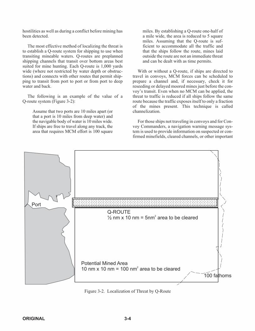
hostilities as well as during a conflict before mining hasbeen detected.
The most effective method of localizing the threat isto establish a Q-route system for shipping to use whentransiting mineable waters. Q-routes are preplannedshipping channels that transit over bottom areas bestsuited for mine hunting. Each Q-route is 1,000 yardswide (where not restricted by water depth or obstruc-tions) and connects with other routes that permit ship-ping to transit from port to port or from port to deepwater and back.
The following is an example of the value of aQ-route system (Figure 3-2):
Assume that two ports are 10 miles apart (orthat a port is 10 miles from deep water) andthe navigable body of water is 10 miles wide.If ships are free to travel along any track, thearea that requires MCM effort is 100 square
miles. By establishing a Q-route one-half ofa mile wide, the area is reduced to 5 squaremiles. Assuming that the Q-route is suf-ficient to accommodate all the traffic andthat the ships follow the route, mines laidoutside the route are not an immediate threatand can be dealt with as time permits.
With or without a Q-route, if ships are directed totravel in convoys, MCM forces can be scheduled toprepare a channel and, if necessary, check it forreseeding or delayed moored mines just before the con-voy’s transit. Even when no MCM can be applied, thethreat to traffic is reduced if all ships follow the sameroute because the traffic exposes itself to only a fractionof the mines present. This technique is calledchannelization.
For those ships not traveling in convoys and for Con-voy Commanders, a navigation warning message sys-tem is used to provide information on suspected or con-firmed minefields, cleared channels, or other important
ORIGINAL 3-4
Q-ROUTE½ nm x 10 nm = 5nm area to be cleared
2
100 fathoms
Port
Potential Mined Area10 nm x 10 nm = 100 nm area to be cleared
2
Figure 3-2. Localization of Threat by Q-Route
navigation information. The MCM commander assiststhe OTC or area commander by maintaining a minesighting list, designating MDAs where necessary, andreporting the status of channels that MCM forces havebeen directed to clear.
3.4.3 Reducing the Risk. The primary passivemethods of reducing the risk for MCM forces are pre-cise navigation and practicing influence signature con-trol. Before the widespread use of satellite navigation,risk reduction included altering navigation aids so thatthe minelayer would be fooled into putting mines in thewrong location. Since the minelayer may not depend onnavigation lights or local radio beacons, this tactic is nolonger as effective as before.
The availability of precise navigation for use by MCMforces, as well as traffic ships, has resulted in a significantreduction of risk for MCM forces. MCM units using GPSP-code are able to pass contact locations from unit to unitand successfully relocate those contacts without signifi-cant searching. The consistency of the GPS and the pre-cise navigation and plotting systems now available toSMCM and AMCM units allow a unit to hunt or sweep atrack and return to that same track later with confidencethat the track the unit is on is the same area that was previ-ously covered, not 50 or 100 yards to either side inuncleared waters. This risk reduction also extends to traf-fic ships using GPS. A GPS-equipped ship can transitwithout a leadthrough vessel when provided the coordi-nates of the cleared channel.
An MCM ship is expected to maneuver in proximityto all kinds of mines. Contact mines can be seen on so-nar and avoided, but there are occasions when an MCMship will maneuver within the sensing range of influ-ence mines. Consequently, the MCM ship must have amagnetic and acoustic signature much smaller than thesignature most mines will be intended to target. Thegreatest danger to an MCM ship is a shallow mooredmine or a sensitive-set influence mine.
The magnetic silencing requirements for MCMships are set by the ship Class Top Level RequirementsDocument and the OPNAV 8950.2 series instruction. Adedicated effort must be maintained to keep the ship’sacoustic and magnetic signatures as low as possible andto complete all degaussing, ranging, and adjustment re-quirements. MCM vessels are scheduled for degauss-ing ranging to update their certification as close aspossible to scheduled deployments, but there are only afew certified ranges where quarterly updates can be ac-complished. U.S. Navy ranges capable of measuringMCM ships are located in Charleston, SC, and San Diego,CA. (The Charleston range may be relocated to Ingleside,
TX.) Other ranges that could be used are located inJapan, Italy, and the United Kingdom. A portable de-gaussing check range was used by British forces duringOperation Desert Storm in the Persian Gulf. Several por-table ranges are being procured by PEO MINEWAR.
Acoustic silencing of MCM ships is much less defined.The Class Top Level Requirements Document includes arequirement for the ship’s acoustic signature, but there isno periodic measuring requirement. Each ship is expectedto follow good maintenance practices and keep equipmentvibration isolation mounts in good working order.
Ships may be equipped with systems intended to pro-tect the ship from influence mines by jamming andspoofing mine sensors. If a mine sensor is designed to beresistant to influence sweeping by signal processing, themine may be rendered temporarily ineffective by gener-ating signals that cause the mine to shut down or make afalse target determination rather than properly detect theship. With the resulting protection from influence minesensors, an MCM ship may be able to successfully ma-neuver in a minefield for hunting or sweeping, or a traf-fic ship may transit a channel with less risk.
Systems that are designed for detection of mines withthe intention of avoiding the mine rather than prosecut-ing it are also classified as passive MCM. Detection andavoidance of mines are less risky (whenever avoidanceis feasible) than active MCM. In the case of MCMforces, avoidance is usually a temporary measure, but forother combatants it is a valid tactic. Additional discus-sion of detection and avoidance is included in Chapter 4.
3.5 ACTIVE MINE COUNTERMEASURES
The two main subsets of active MCM are mine hunt-ing and minesweeping.
3.5.1 Mine Hunting. Mine hunting is determiningthe location of individual mines so that countermea-sures may be taken to avoid, remove, render harmless,or destroy each mine. It is a one-on-one operation, un-like sweeping, during which process all mines in theswept path are addressed at the same time.
Mine hunting performance is not affected by thetype of mine firing mechanism in the mine, the sensitiv-ity settings of the mechanism, ship count settings, orarming delays. Even delayed mooring mines can be de-tected by a bottom search.
Mine hunting operations are affected by the degree towhich mines are buried, mine casing construction and
3-5 ORIGINAL
material, clutter on the sea bottom, and many other en-vironmental factors.
3.5.1.1 Mine Hunting Process. The mine hunt-ing process includes the following:
1. Detection — Potential minelike contacts arenoted for further investigation.
2. Classification — The detected contact is furtherinvestigated, usually with a higher resolution so-nar, and classified as a MILC or NOMBO.Equipment operators use all available featuresof the mine hunting system to examine a contact,possibly maneuvering to view a different aspectof the object. If the contact cannot be classifiednonminelike with confidence, it will be called aMILC until identification proves otherwise.
3. Localization — The contact position is refinedand plotted as precisely as possible (specifyingnavigation sensor, datum, and position in lati-tude/ longitude to a thousandth of a minute) sothat further prosecution can be carried out eitherimmediately or at a later time. MCM forces usethe WGS-84 datum as measured by GPS P-codeas the standard reference system.
4. Identification — The contact is investigated eitherby an EODMCM diver or ROV using video cam-era and sonar. Identification should be made usingan optical system so that a positive ID of the minecan be made. This prevents expenditure of neutral-ization efforts and charges on nonthreatening ob-jects. It also keeps the MCM forces from assuminga minefield exists where there is none.
5. Neutralization — The mine is either rendered in-operative or removed from the area. Paragraph3.5.4 provides details of neutralization methods.
Though not a step in the mine hunting process, theprosecution of a contact should not be considered com-plete until details of the mine contact are reported to theMCM Commander using standard MCM reportingformats.
Since a neutralization charge does not provide posi-tive evidence of success on the surface or on sonar, it isimportant to confirm, by diver or ROV inspection, thatmines have indeed been neutralized. Verification maybe performed immediately after neutralization if theoperation is not on a critical time schedule. Otherwise,it should be done as an administrative cleanup actionafter the MCM objective has been attained.
3.5.1.2 Types of Mine Hunting. Acoustic minehunting is the use of active sonars (including marinemammals) to find objects with minelike characteristics.SMCM and AMCM mine hunting sonars use a videodisplay of the acoustic signal only and do not use audio,as is common in ASW sonars. Acoustic mine hunting iseffective against mines with metallic cases or othercases that provide sufficient echo. Mines partially bur-ied in mud or sand can be detected up to a point in mar-ginal environmental conditions. The Mk 7 Mod 1Marine Mammal System can be used to locate buriedmines. Moored mines can be located by detection of thecase, by detection of the anchor, or by the echo from themine mooring cable.
Magnetic mine hunting is the use of magnetic detec-tors to find ferro-magnetic mines proud of the sea bedor buried. The detection range of magnetic systems istypically very short, making them unsuitable formounting in ships. Devices that are towed close to thesea bottom have been tested. The difficulty with mag-netic detectors is classifying contacts as minelike. Witha simple magnetic detector, the only indication is therelative signature of the magnetic object. Currently nomagnetic mine hunting systems are operational forshipboard or aircraft use. Developmental programs arein progress that link magnetic detectors with sonar andother sensors attempting to develop an effective combi-nation. There are diver-carried magnetic locators, butthese have limite d use in MCM operations.
Optical mine hunting is the use of visual, optical, orelectro-optical systems to find mines on the surface, inthe volume, or on the sea bed. The primary limiting fac-tor with optical systems is the poor light transmissionquality of seawater. The air bubbles, marine life, andsuspended matter in seawater scatter light rays veryquickly so that light wave frequencies visible to the hu-man eye do not perform well. Even so, the best opera-tional optical system is a visual search. Conducted froma helicopter, a visual search can be effective againstmines on or near the surface. Ships’ lookouts are alsoeffective against mines on the surface if properlytrained, equipped, and stationed. Chapter 4 providesadditional detail on visual search methods and equip-ment. Developmental programs are underway for dedi-cated mine detection systems that use laser optics andinfrared frequencies, but none is fielded yet.
Detection of mines on the surface, particularly drift-ing mines, has also been attempted using aircraft radarsystems. Results have not indicated radar to be a de-pendable method for detection, although some successhas been observed.
ORIGINAL 3-6
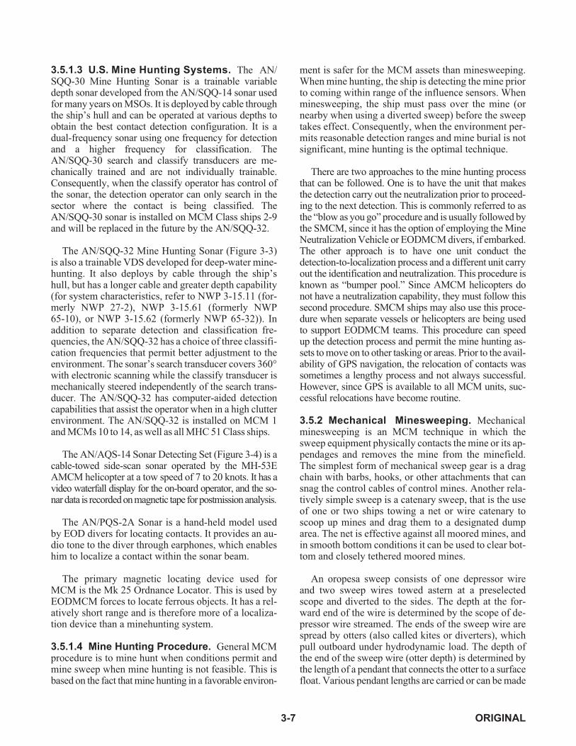
3.5.1.3 U.S. Mine Hunting Systems. The AN/SQQ-30 Mine Hunting Sonar is a trainable variabledepth sonar developed from the AN/SQQ-14 sonar usedfor many years on MSOs. It is deployed by cable throughthe ship’s hull and can be operated at various depths toobtain the best contact detection configuration. It is adual-frequency sonar using one frequency for detectionand a higher frequency for classification. TheAN/SQQ-30 search and classify transducers are me-chanically trained and are not individually trainable.Consequently, when the classify operator has control ofthe sonar, the detection operator can only search in thesector where the contact is being classified. TheAN/SQQ-30 sonar is installed on MCM Class ships 2-9and will be replaced in the future by the AN/SQQ-32.
The AN/SQQ-32 Mine Hunting Sonar (Figure 3-3)is also a trainable VDS developed for deep-water mine-hunting. It also deploys by cable through the ship’shull, but has a longer cable and greater depth capability(for system characteristics, refer to NWP 3-15.11 (for-merly NWP 27-2), NWP 3-15.61 (formerly NWP65-10), or NWP 3-15.62 (formerly NWP 65-32)). Inaddition to separate detection and classification fre-quencies, the AN/SQQ-32 has a choice of three classifi-cation frequencies that permit better adjustment to theenvironment. The sonar’s search transducer covers 360°with electronic scanning while the classify transducer ismechanically steered independently of the search trans-ducer. The AN/SQQ-32 has computer-aided detectioncapabilities that assist the operator when in a high clutterenvironment. The AN/SQQ-32 is installed on MCM 1and MCMs 10 to 14, as well as all MHC 51 Class ships.
The AN/AQS-14 Sonar Detecting Set (Figure 3-4) is acable-towed side-scan sonar operated by the MH-53EAMCM helicopter at a tow speed of 7 to 20 knots. It has avideo waterfall display for the on-board operator, and the so-nardata is recorded onmagnetic tape for postmissionanalysis.
The AN/PQS-2A Sonar is a hand-held model usedby EOD divers for locating contacts. It provides an au-dio tone to the diver through earphones, which enableshim to localize a contact within the sonar beam.
The primary magnetic locating device used forMCM is the Mk 25 Ordnance Locator. This is used byEODMCM forces to locate ferrous objects. It has a rel-atively short range and is therefore more of a localiza-tion device than a minehunting system.
3.5.1.4 Mine Hunting Procedure. General MCMprocedure is to mine hunt when conditions permit andmine sweep when mine hunting is not feasible. This isbased on the fact that mine hunting in a favorable environ-
ment is safer for the MCM assets than minesweeping.When mine hunting, the ship is detecting the mine priorto coming within range of the influence sensors. Whenminesweeping, the ship must pass over the mine (ornearby when using a diverted sweep) before the sweeptakes effect. Consequently, when the environment per-mits reasonable detection ranges and mine burial is notsignificant, mine hunting is the optimal technique.
There are two approaches to the mine hunting processthat can be followed. One is to have the unit that makesthe detection carry out the neutralization prior to proceed-ing to the next detection. This is commonly referred to asthe “blow as you go” procedure and is usually followed bythe SMCM, since it has the option of employing the MineNeutralization Vehicle or EODMCM divers, if embarked.The other approach is to have one unit conduct thedetection-to-localization process and a different unit carryout the identification and neutralization. This procedure isknown as “bumper pool.” Since AMCM helicopters donot have a neutralization capability, they must follow thissecond procedure. SMCM ships may also use this proce-dure when separate vessels or helicopters are being usedto support EODMCM teams. This procedure can speedup the detection process and permit the mine hunting as-sets to move on to other tasking or areas. Prior to the avail-ability of GPS navigation, the relocation of contacts wassometimes a lengthy process and not always successful.However, since GPS is available to all MCM units, suc-cessful relocations have become routine.
3.5.2 Mechanical Minesweeping. Mechanicalminesweeping is an MCM technique in which thesweep equipment physically contacts the mine or its ap-pendages and removes the mine from the minefield.The simplest form of mechanical sweep gear is a dragchain with barbs, hooks, or other attachments that cansnag the control cables of control mines. Another rela-tively simple sweep is a catenary sweep, that is the useof one or two ships towing a net or wire catenary toscoop up mines and drag them to a designated dumparea. The net is effective against all moored mines, andin smooth bottom conditions it can be used to clear bot-tom and closely tethered moored mines.
An oropesa sweep consists of one depressor wireand two sweep wires towed astern at a preselectedscope and diverted to the sides. The depth at the for-ward end of the wire is determined by the scope of de-pressor wire streamed. The ends of the sweep wire arespread by otters (also called kites or diverters), whichpull outboard under hydrodynamic load. The depth ofthe end of the sweep wire (otter depth) is determined bythe length of a pendant that connects the otter to a surfacefloat. Various pendant lengths are carried or can be made
3-7 ORIGINAL
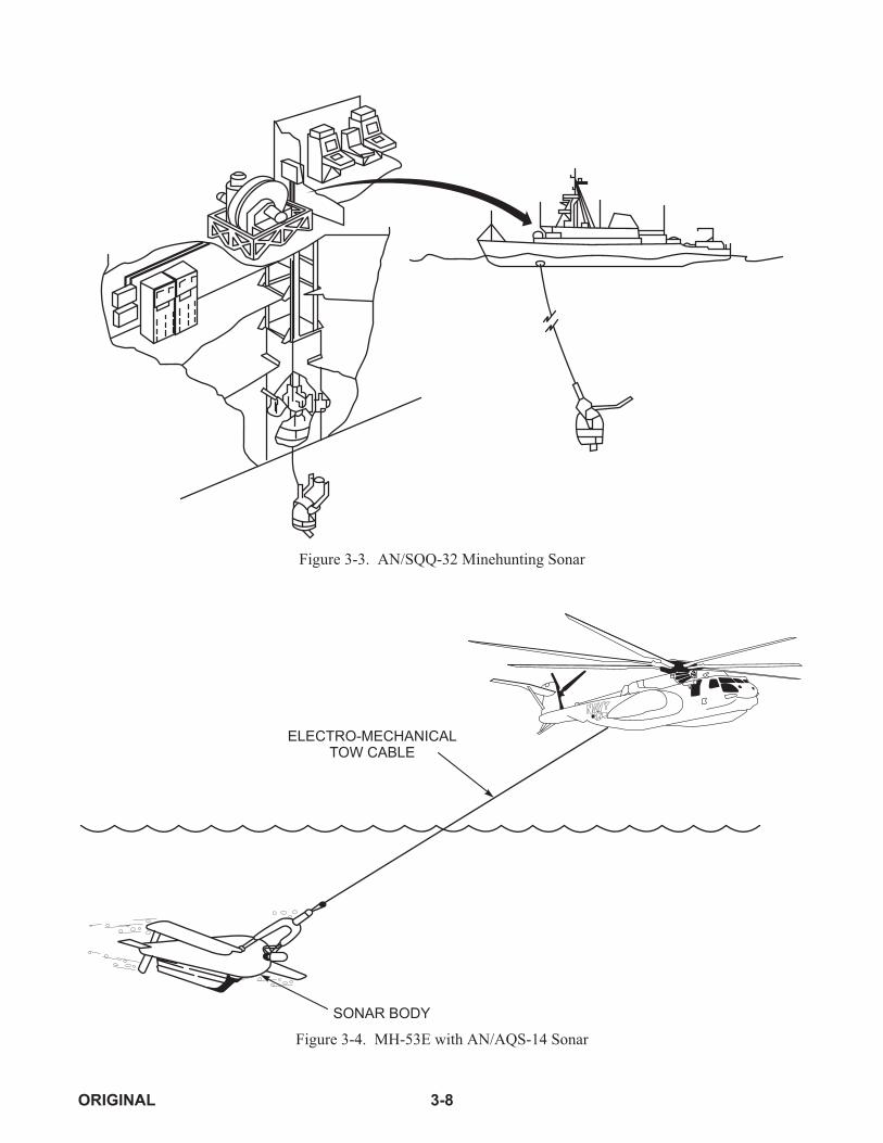
ORIGINAL 3-8
Figure 3-3. AN/SQQ-32 Minehunting Sonar
ELECTRO-MECHANICALTOW CABLE
SONAR BODY
Figure 3-4. MH-53E with AN/AQS-14 Sonar
up on the ship. Mooring cables are cut either by abra-sion by the sweep wire or mechanical or explosive cut-ters mounted on sweep wire, which can sever mooringcables from 1/4-inch cable to 1 1/2-inch chain.
Against moored mines, oropesa mechanical sweepsare designed to cut the mooring cable so that the minecomes to the surface. Unless the mine has someantidisturb function or antirecover hydrostatic actuator,once the mooring is cut, the mine is converted to a drift-ing mine (usually still functional). These drifting minesmust be disposed of, preferably by EODMCM diversoperating from another ship or helicopter.
In mechanical sweeping by surface ships, the ship isobliged to transit the mined area before the sweep, actu-ating any moored mines less than the ship’s draft.AMCM helicopters can mechanically sweep withoutbeing exposed to the mines. Consequently, modern tac-tics dictate a precursory sweep by AMCM assets forsweeper safety or require sweeping the first track insafe water with the sweep diverted into the mined area.
The AN/SLQ-38 Mechanical Minesweep System (inFigure 3-5) is an oropesa sweep installed on theMCM-1 Class. Sweep characteristics are provided inNWP 3-15.11 (formerly NWP 27-2).
The DMS is a variation of the AN/SLQ-38 sweep inwhich the wire is streamed on one side only and an ex-tra depressor is used. The swept path is narrower, butthe depth can be increased. This sweep has also been re-ferred to as the Single Ship Deep Sweep. The IDMSvariation of the AN/SLQ-38 sweep hooks the sweepwire from two ships together to be towed like a catenarysweep. Depths of 2,000 feet can be reached using thissweep, but it is difficult to be sure of the swept path. If athird ship is available, it may use sonar to track thesweep and vector it towards mine contacts.
The Mk-103 Mechanical Sweep is a modifiedoropesa-style sweep used by AMCM helicopters. Thedepth of this sweep is determined entirely by selecting pen-dants that attach the sweep wire to surface floats at severalpoints. This sweep may also be towed by the MCAC.
A new sweep system developed to provide increaseddepth capability for AMCM use is the A/N37-U Con-trolled Depth Sweep shown in Figure 3-6. It is similar indesign to oropesa gear, but depth is determined by con-trol surfaces on the depressor and otters. One depressorand each otter has a water-driven turbine generator thatpowers control circuitry. Depth sensors are used tovary the control surfaces and maintain the indicateddepth. Additional depressors, without adjustable sur-
faces, may be necessary as depth increases. No surfacefloats are required.
The AN/SLQ-53 Single Ship Deep Sweep is a sur-face version of the A/N-37U packaged as a modularmechanical sweep for the MHC 51 Class ships. Apalletized winch mounts on the ship’s fantail alongwith storage containers for the sweep gear. The towedgear is identical to the aircraft towed gear.
3.5.3 Influence Minesweeping. Influence minesweeping is intended to satisfy the mine sensor andhave it detonate at a safe distance from the sweeper. In-fluence mine sweeping includes magnetic influence,acoustic influence, and combination influence sweep-ing. There is no minesweeping system for pressure minesensors. If pressure sensors are encountered, mine hunt-ing is the technique that should be used. The alternativeis a guinea pig ship that can satisfy the pressure sensorand detonate the mines. These ships are usually modifiedcargo ships with additional flotation material to preventthem from sinking and blocking a channel. The guineapig is intended to absorb the damage from several minedetonations before being repaired or scrapped.
There are two tactical approaches to influence minesweeping. One is to take advantage of the weaknesses inthe target discrimination ability of mines by producingan influence signature that will sweep all mines in thefield of a particular type or setting. This allows the use ofhigh-energy sources that have large sweep widths eventhough the signatures are not exactly ship-like. To deter-mine the required sweep characteristics, exploitation andanalysis must have been conducted on the mines. U.S.Navy influence sweeps are designed for this tactic.
The other approach is to produce an influence signa-ture that emulates the type of ship expected to transitand sweep all mines that are a threat to that ship. Theemulation approach does not require knowledge of themines present, but it does require knowledge of the spe-cific signature of transiting ships and may require amore sophisticated sweep system.
3.5.3.1 Magnetic Minesweeping. In magneticmine sweeping, whether single-influence or combination-influence minesweeping (which includes a magneticcomponent), the magnetic field of the surface mine-sweeper must be small enough to let it pass over themine without satisfying the mine sensor. Also, the mag-netic field generated by the sweep must be far enoughastern of the sweeper so that a magnetic mine is not ac-tuated until the ship is at a safe distance. When a minehas a shipcount setting, the magnetic field of somesweeps can be pulsed to simulate several ships passing.
3-9 ORIGINAL
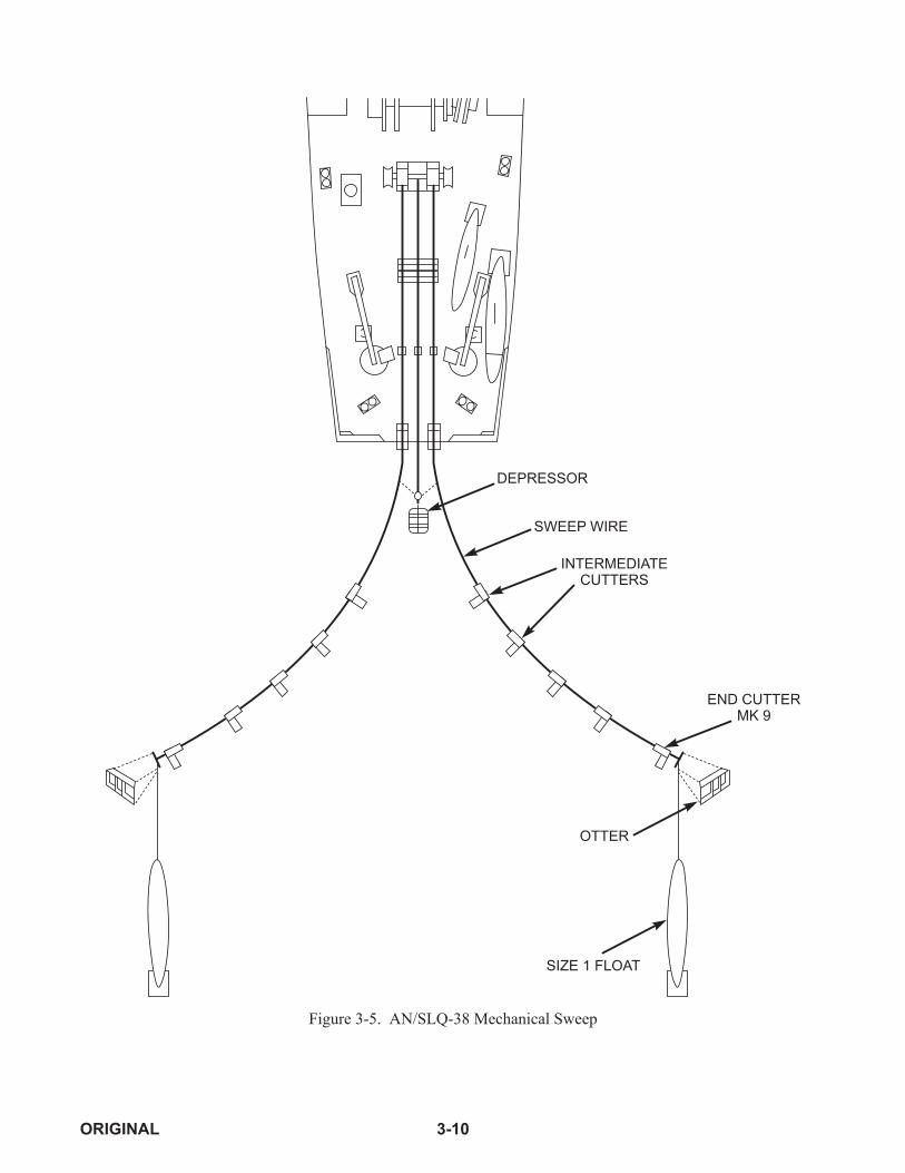
ORIGINAL 3-10
DEPRESSOR
SWEEP WIRE
INTERMEDIATECUTTERS
END CUTTERMK 9
OTTER
SIZE 1 FLOAT
Figure 3-5. AN/SLQ-38 Mechanical Sweep
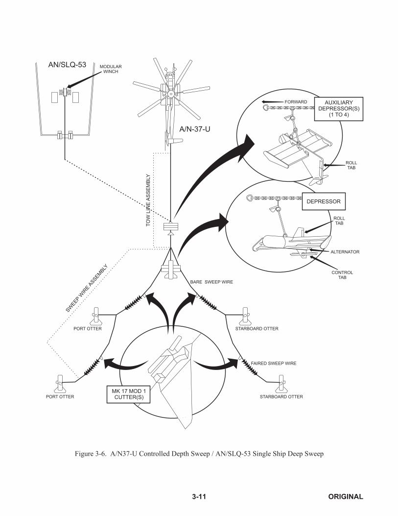
3-11 ORIGINAL
AN/SLQ-53 MODULARWINCH
FORWARD
ROLLTAB
ROLLTAB
ALTERNATOR
CONTROLTAB
STARBOARD OTTER
STARBOARD OTTER
FAIRED SWEEP WIRE
BARE SWEEP WIRE
PORT OTTER
PORT OTTER
A/N-37-U
AUXILIARYDEPRESSOR(S)
(1 TO 4)
DEPRESSOR
MK 17 MOD 1CUTTER(S)
TO
WL
INE
AS
SE
MB
LY
SW
EEP
WIR
EASSEM
BLY
Figure 3-6. A/N37-U Controlled Depth Sweep / AN/SLQ-53 Single Ship Deep Sweep
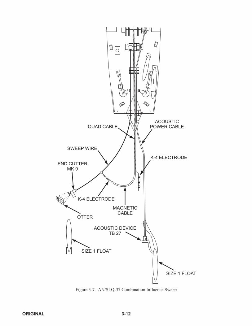
ORIGINAL 3-12
ACOUSTICPOWER CABLE
K-4 ELECTRODE
QUAD CABLE
SWEEP WIRE
END CUTTERMK 9
K-4 ELECTRODE
MAGNETICCABLE
OTTER
ACOUSTIC DEVICETB 27
SIZE 1 FLOAT
SIZE 1 FLOAT
Figure 3-7. AN/SLQ-37 Combination Influence Sweep
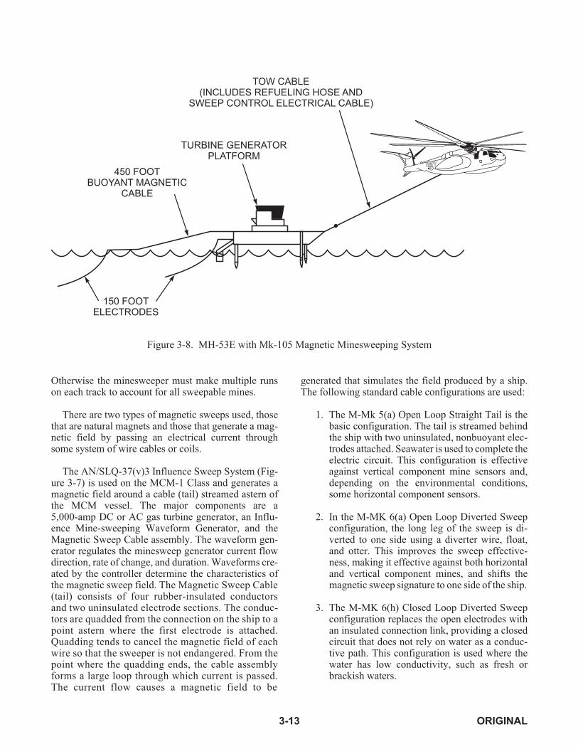
Otherwise the minesweeper must make multiple runson each track to account for all sweepable mines.
There are two types of magnetic sweeps used, thosethat are natural magnets and those that generate a mag-netic field by passing an electrical current throughsome system of wire cables or coils.
The AN/SLQ-37(v)3 Influence Sweep System (Fig-ure 3-7) is used on the MCM-1 Class and generates amagnetic field around a cable (tail) streamed astern ofthe MCM vessel. The major components are a5,000-amp DC or AC gas turbine generator, an Influ-ence Mine-sweeping Waveform Generator, and theMagnetic Sweep Cable assembly. The waveform gen-erator regulates the minesweep generator current flowdirection, rate of change, and duration. Waveforms cre-ated by the controller determine the characteristics ofthe magnetic sweep field. The Magnetic Sweep Cable(tail) consists of four rubber-insulated conductorsand two uninsulated electrode sections. The conduc-tors are quadded from the connection on the ship to apoint astern where the first electrode is attached.Quadding tends to cancel the magnetic field of eachwire so that the sweeper is not endangered. From thepoint where the quadding ends, the cable assemblyforms a large loop through which current is passed.The current flow causes a magnetic field to be
generated that simulates the field produced by a ship.The following standard cable configurations are used:
1. The M-Mk 5(a) Open Loop Straight Tail is thebasic configuration. The tail is streamed behindthe ship with two uninsulated, nonbuoyant elec-trodes attached. Seawater is used to complete theelectric circuit. This configuration is effectiveagainst vertical component mine sensors and,depending on the environmental conditions,some horizontal component sensors.
2. In the M-MK 6(a) Open Loop Diverted Sweepconfiguration, the long leg of the sweep is di-verted to one side using a diverter wire, float,and otter. This improves the sweep effective-ness, making it effective against both horizontaland vertical component mines, and shifts themagnetic sweep signature to one side of the ship.
3. The M-MK 6(h) Closed Loop Diverted Sweepconfiguration replaces the open electrodes withan insulated connection link, providing a closedcircuit that does not rely on water as a conduc-tive path. This configuration is used where thewater has low conductivity, such as fresh orbrackish waters.
3-13 ORIGINAL
TOW CABLE(INCLUDES REFUELING HOSE AND
SWEEP CONTROL ELECTRICAL CABLE)
TURBINE GENERATORPLATFORM
450 FOOTBUOYANT MAGNETIC
CABLE
150 FOOTELECTRODES
Figure 3-8. MH-53E with Mk-105 Magnetic Minesweeping System
The SAM is a Swedish-built, diesel-propelled,remote-control catamaran craft. It has two pontoonhulls built of foam-filled GRP with built- in solenoidcoils. The center platform, which supports the pro-pulsion system and generator, also has a closed-loopcoil around the perimeter. The SAM is used in shallowwater or inshore operations but is limited by speed andsea state for open-water operations.
The SPU-1/W MOP is a towed magnetic sweep thatwas developed for AMCM use in shallow water, as wellas fresh and brackish water. The MOP is a ferrous metalpipe that is 30 feet long, 10 3/4 inches in diameter, andweighs 1,000 pounds. It is filled with polystyrene foamto provide buoyancy and is capped at both ends withpadeyes to allow towing from either end. The MOP mustbe remagnetized using a magnetic coil prior to each mis-sion. It does not have a large magnetic field and is lim-ited to use in water where other sweeps cannot be used.Up to three MOPs may be towed together by theMK-53E helicopter to increase the coverage provided.
The Mk-105 Magnetic Minesweeping System (Figure3-8) is a hydrofoil sled towed by the MH-53E AMCM heli-copter. Mounted on the sled is a 2,000-amp gas turbinegenerator. The generator functions are controlled from thehelicopter, and constant current or pulsed modes are avail-able. The in-water portion of the sweep is an open loopelectrode set. The device will sweep both vertical and hor-izontal component mines in water as shallow as 12 feet.
Components of the Mk-105 system are used whenoutfitting an MCAC (LCAC converted for MCM oper-ations) for magnetic sweeping.
3.5.3.2 Acoustic Mine weeping. Acoustic minesweeping is that portion of influence minesweeping in-volved in generating an acoustic signal to satisfy a pas-sive acoustic mine sensor and may also include systemsto respond to active acoustic sensors.
Acoustic sweep systems may be simple mechanicaldevices, combination electromechanical devices, or allelectronic devices.
U.S. Navy Acoustic Sweep Systems include thefollowing:
1. A-MK-2(g) Rattlebars are a mechanical sweepconsisting of closely fixed parallel pipes towedthrough the water. Water flowing through thepipes creates a venturi effect, which causes thepipes to bang together and produce the acousticoutput. The acoustic frequency generated is un-controlled medium- to high-frequency broadband
noise. The sweep is very effective but has asmall actuation width because of limited vol-ume. Frequency and volume are dependent ontow speed, but the device will self-destruct iftowed too fast. An A-MK-2(g) is used in shal-low water to simulate hull noise and cavitation.
2. The AN/SLQ-37 Influence Sweep System (acous-tic components) is an old technology electro-mechanical system installed on the MCM-1 Classships. It has an Acoustic Controller on the ship,which provides power via the tow cable to operatetowed devices. Control options include steadystate operation, modulated operation (which iscontinuous operation with alternating high andlow output levels), and pulsed operation (which iscycles of high-level output followed by an offperiod). There are two towed devices:
3. The TB 26, originally called A-MK-6(b), is alow-frequency device that contains electricallydriven eccentric oscillating diaphragms to createthe acoustic signal. The eccentrics can bechanged to alter the frequency range.
4. The TB-27, originally called A-MK-4(v), is amedium frequency device with an electric motor-driven hammer striking a steel diaphragm tocause broadband noise. It can be operated insteady, pulsed, or modulated patterns.
5. Mk-104 Acoustic Minesweeping Gear is towedby MH-53E AMCM helicopters. It consists ofan upper buoyant section and a lower sound-producing mechanism. The lower section containstwo rotating disks inside venturi tube assemblies.Water flow causes the disks to rotate and cause acavitation effect in the venturi tube. This produces asteady acoustic output. A drag brake system permitsthe output frequency to be preset before the deviceis streamed from the helicopter.
3.5.4 Mine Neutralization. Countermining or counter-charging is mine disposal by using an explosive chargeto cause sympathetic high-order detonation of the mine.The size of explosion should leave no doubt thatcountermining was successful. The major advantage tocountermining is that it does not leave a minelike contact toclutter the environment. A disadvantage is that it requires alarge explosive charge and/or closer placement to the mine,which may involve higher risk to the diver or ROV.
Mine neutralization is rendering a mine inoperativeby using an explosive charge sized and placed to eitherdamage the mine mechanism or rupture and flood the
ORIGINAL 3-14

case by overpressure. Following detonation of theneutralization charge, the mine case may continue tolook like a mine on sonar. If time permits, a post-neutralization inspection should be made to verify thatthe mine is neutralized. This may occur as part of an ad-ministrative cleanup after any time-sensitive objectiveshave been attained. The major disadvantage to neutral-ization as compared to countermining is that it leaves amine case with explosives on the bottom, which maycontribute to bottom clutter.
Relocation of a mine to an area where it presents nohazard is called removal. This method might be used formines located where detonation could cause damage topipelines, wellheads, docks, or other fixtures. It is alsoused when trawl nets are employed for sweeping andmines are swept but do not detonate. Since mines will bea hazard wherever they are relocated, countermining orneutralization is still necessary, but it could be done astime permits where explosions represent no hazard toother facilities or units.
Recovery of a mine is conducted when exploitation oranalysis is necessary. The purpose of exploitation is tocollect intelligence data on how the mine operates or touse the mine for laboratory analysis to develop MCM tac-tics against that mine type. The purpose may also be to de-termine what types of mines are present and what settingsare in use so that sweeping can be done more effectively.
A RSP is performed to render a mine inoperative byinterruption of operating functions or separation of es-sential components prior to or during recovery.
EODMCM detachments are most effective whenpermitted to work independent of other MCM forces toconduct neutralization. The GPS permits the EOD teamto relocate contacts previously localized by SMCM orAMCM. Using GPS, the EODMCM detachment ar-rives at the mine position by inflatable boat or othersupport craft. The diver relocates the mine by a visualsearch around the position or by using the PQS-2Ahand-held sonar, then places the explosive charge. Thistechnique is limited to the diver’s operating depth of200 feet (300 feet with Type II emergency breathingequipment). Divers cannot go to this depth continuallybecause they become saturated with nitrogen gas.
The main battery of the MCM/MHC class ships formine disposal is the AN/SLQ-48 Mine NeutralizationSystem. This is a remotely operated, tethered MNV,which is powered down the cable. The MNV is equippedwith a short-range sonar for contact location and termi-nal guidance. It also has lights and a high-resolution tele-vision camera for contact identification. The MNV isplaced in the water from a specialized handling system
capable of operation up to sea state 3. The vehicle isthen piloted into the sonar beam and vectored to the vi-cinity of the contact by the sonar operator. The vehiclepilot then approaches the contact based on his vehiclesonar and TV monitor. Mission time is dependent onweather, depth, current, and other factors, but it aver-ages 30 to 45 minutes per contact.
The MNV can carry two explosive cable cutters formoored mine cables or an explosive bomblet for bottommine neutralization. The cable cutters simply reclassifythe mine as a drifting mine that must be counterchargedby divers. A new mission package that is now under de-velopment will permit in-place countermining formoored mines. The MNS is installed on all MCM-1 andMHC-51 Class ships.
Chapter 4 discusses mine disposal procedures fornon-MCM forces.
3.5.5 Mine Exploitation. For an influence minesweeping operation to be successful, the sweep charac-teristics must to be matched to the mine settings. Insome cases, with mixed mine types or mixed settings,multiple sweeping runs may be required. Unless otherintelligence sources have provided data on the minesettings, the recovery and exploitation of several minesto determine their settings should be one of the highestpriorities of the MCM Commander.
After field exploitation, the mine may be shipped tothe EOD Technology Division at Indian Head, MD,and Coastal Systems Station, Panama City, FL, fortechnical exploitation and analysis. If the mine is an un-known type or new modification, a full exploitation andanalysis to determine sweep tactics should be done. Af-ter sufficient exploitation has been conducted, mines ofa type that have previously been exploited and analyzedmay be disposed of by countercharging.
3.5.6 Brute Force Mine Clearance. Brute forcerefers to the highly desirable but rarely practical require-ment to clear or neutralize the mines in an area all at once.It is theorized that by the use of a large enough force, sym-pathetic detonation or neutralization of all the mines in anarea could be accomplished in the same instant. While intheory it is possible, in practice it has not yet proven to befeasible. Attempts have been made using saturation bomb-ing and naval gunfire, with little success. However, these ex-plosives delivery methods do not provide a uniformdistribution of force over the area. Thus, while some minesmay be detonated and others damaged, the commander can-not, with confidence, consider the area to be cleared to a safelevel. Further development is ongoing with systems (such asline charges and explosive nets) that can provide a more
3-15 ORIGINAL
even distribution of explosives which can be detonated allat once. In the near future, it may be possible to clear thesurf zone or other shallow-water zones with brute forcetechniques.
3.6 INTEGRATED MINE COUNTERMEA-SURES OPERATIONS
MCM operations require a variety of assets equippedwith MCM capabilities to overcome the mixture of oldand new mines that are in use today. Integrated opera-tions involve the coordinated planning and applicationof these assets to achieve the objectives in the safest,most expedient manner. There are four basic steps to anintegrated MCM operation:
1. Determine the tactical objective
2. Assess the threat
3. Assess MCM asset capabilities
4. Develop and implement a tactical plan.
The battle group or CATF (with advice from theMCM commander) will determine the MCM objectiveby considering general knowledge of the minefield loca-tion and enemy mission, the urgency of need to transitthe area, and the acceptable degree of risk for MCM as-sets and traffic vessels. Assessment of the threat is a con-tinuing process that must include the threat from themines that might be encountered, the threat resultingfrom or compounded by the environment in which theoperation must occur, and the threat from hostile forces.In assessing MCM asset availability, capabilities, andutilization, the MCM commander must evaluate the ca-pability of each asset against each confirmed or sus-pected mine type and combination of types, evaluate thelogistic support requirements for each asset type, andthereby determine the utilization factors of each asset.
Asset strengths that are exploited where possible in-clude the following:
1. SMCM long operational endurance
2. SMCM influence sweep versatility
3. SMCM deep hunt, neutralize, and sweep ability
4. AMCM invulnerability to mines
5. AMCM speed at hunting and sweeping
6. AMCM shallow water sweep ability
7. EODMCM independent identify and neutralizeability
8. MMS shallow water and buried mine capability.
Asset weaknesses to be worked around include thefollowing:
1. SMCM shallow water limits
2. SMCM vulnerability to mines
3. AMCM daylight only limits
4. AMCM inability to identify and neutralize
5. EOD/NSW environmental and bottom timelimitations
6. EODMCM diver endurance.
Having considered individual asset capabilities, theMCM commander must now integrate those assets intoa tactical plan that will exploit strengths and minimizeweaknesses. Common aspects of an integrated planmay include rapid reconnaissance by AMCM to helprefine planning for each area, precursor sweeping byAMCM to protect the SMCMV against sensitive influ-ence mines and shallow moored contact mines, or pre-cursory hunting by AMCM to determine the presenceof moored mines. Once the tactical plan is prepared andimplemented, it must be continuously reevaluated us-ing the most current threat information to determinewhether the plan needs to be modified and whether it isaccomplishing the objectives as intended.
The battle group and MCM commander may also re-quest MPA or national assets. These assets can monitorthe area of operations to localize the mine threat and de-termine which forces pose a threat to MCM assets.NSW may be requested to assist in VSW operations.Air and surface platforms may be needed to provide de-fense for the MCM forces if operating in or near hostileenvironments.
3.7 COMBINED MINE COUNTERMEASURESOPERATIONS
Combined MCM operations are those conductedwith a combination of U.S. and Allied MCM forces(NATO and/or other nations’ assets). These multina-tional operations may involve forces used to operatingunder different doctrine, different tactical procedures,and with limited connectivity in C4I systems. To deter-mine the best tactical application of all available assets,planning for combined operations can follow the same
ORIGINAL 3-16
procedure as for integrated operations. However, com-bined operations are sometimes affected by nationalpolitical limitations which prevent free employment ofsome national forces. An example might be the prohibi-tion of force employment in the territorial waters of theaggressor nation or as an integrated force with someother nation’s assets. Although these limitations willcomplicate the planning problem, the same tactical ap-proach (considering all asset capabilities and limita-tions) can be followed.
3.7.1 Primary NATO/Allied MCM Assets. MCMhas been a high priority for many European countriesduring the Cold War years. Many NATO countrieshave been mined before and continue to face mineproblems that are both left over from World Wars I andII and a result of the former Soviet threat.
The U.S. MCM-1 Class was developed to counterthe ASW mining threat by the former U.S.S.R. (a deepwater threat). The threat most NATO countries plannedagainst was a shallow-water ASUW mining effort tostop troop movement and commerce. This is reflectedin the capabilities and design of each country’s forces.Forces and tactics are developed to suit the individualneeds of each country, not necessarily to fill particularshortcomings in the NATO organization.
The following paragraphs highlight most of the signifi-cant NATO/Allied platforms. For additional detail andcurrent numbers, recommended references are as follows:
1. DST-1260H-061-yr, Naval Weapons Systems,Less Missiles
2. DST-1260H-110-yr, Mine Warfare Capabil-ities: Selected Eastern European Countries
3. DST-1260H-120 yr, Naval Mines & MCM: Restof World less Eastern Europe
4. COMINEWARCOM MIW Assessment ofNATO/Allied Nations
5. Jane’s Fighting Ships.
3.7.1.1 Great Britain. Great Britain has an excel-lent MIW capability, which includes a career path forofficers and enlisted personnel who wish to remain inthe MCM community. Divers are an integral part ofeach ship’s crew rather than a separate force. The FSUis a mobile engineering support unit that deploys tosupport British MCM forces as necessary, and an MCMforce will normally deploy with a support ship with anMCMTA embarked.
There are 13 British HUNT Class ships. Their char-acteristics are as follows:
1. Conventional GRP frame structure with GRPhull covering
2. Very low magnetic signature
3. Hydraulic auxiliary propulsion for mine hunting
4. Hull mounted 193M minehunting sonar
5. PAP-104 identification/neutralization ROV
6. Mechanical, magnetic, and acoustic sweep.
There are 12 British SANDOWN Class ships; theyare new and similar to the MHC-51 in capability.
1. GRP construction
2. Nonmagnetic diesel with Voith Schneiders andbow thruster
3. Electric auxiliary propulsion for mine hunting
4. Marconi 2093 VDS minehunting sonar
5. PAP-104 identification/neutralization ROV
6. Nautis M tactical display/command and controlsystem.
3.7.1.2 France. France has a strong MCM force andmaintains a serious route survey program. It maintains10 ERIDAN Class (TRIPARTITE) ships. TRIPAR-TITE was a joint French, Dutch, and Belgian project tobuild mine hunters. Each built its own GRP hull but usedFrench electronics, Belgian electrical equipment, andDutch engines. Each have the following characteristics:
1. Two electrical active rudders for MH propulsion
2. DUBM 21A hull mounted sonar
3. PAP 104 identification/neutralization ROV
4. Mechanical sweep system.
3.7.1.3 Netherlands/Belgium. Eguermin, perhapsthe best MCM school in the world (a bilateral agree-ment between the Netherlands and Belgium), is lo-cated in Oostende, Belgium. In addition to a museum,it has a complex simulator that can simulate anyMCM unit in the world against any mine threat in the
3-17 ORIGINAL
world, and is used to run full interactive planning prob-lems. The new Mine Warfare Training Center in Texasis patterned after Eguermin. The Netherlands has 15TRIPARTITE minehunter/sweepers. Belgium hasseven TRIPARTITE mine hunter/sweepers and twocommand and support ships.
3.7.1.4 Germany. Germany has a very strong minewarfare program with very active and capable miningand MCM programs. The following are Germany’sMCM inventory and ship characteristics:
1. Six ELBE Class tenders for logistics support toMCM and FPBs
2. Ten Type 332 MHC ships
a. Nonmagnetic steel hull
b. Electric minehunting propulsion motor
c. Hull-mounted minehunting sonar
d. Two Penguin mine identification/counter-mining ROVs
3. Ten Type 343 Class MSC ships
a. Sweeper version of Type 332 without electricpropulsion
b. Full sweep suite
c. Mine avoidance sonar
4. Ten Type 331 MHC ships
a. Constructed as sweeper then converted tohunter
b. Hull-mounted minehunting sonars
c. PAP 105 mine identification/neutralizationROV
d. Mechanical sweep system.
5. Six Type 351 TROIKA ships
a. Same as 331 but converted to Troika controlship rather than hunter
b. Controls three acoustic/magnetic sweepingdrones by radar tracking and radio link
c. Retains mechanical sweep system.
3.7.1.5 Norway. Mining has priority in Norwaywhere 50 percent of coastal waters are unsuitable formine hunting, but they have recently built a newSMCM ship. Norway’s MCM assets include fourOSKOY Class (MHC) ships and five ALTA Class(MSO) ships. The following are their characteristics:
1. New class, first commissioned June 1994
2. GRP catamaran operating on surface effect be-tween two hulls
3. Two diesel engines, two waterjet propulsionunits
4. MHC fitted with hull-mounted sonar and twoPluto ROVs
5. MSO fitted with mine avoidance sonar and me-chanical and influence sweep system.
3.7.1.6 Denmark. In Denmark, mining also has pri-ority, and MCM assets are multipurpose ships. Thecountry has 14 FLYVEFISKEN Class mine hunter/layer ships with six MCM suites. They have the follow-ing characteristics:
1. Stanflex 300 common hull and prop for MCM,patrol, attack, and minelayer variants
2. GRP hull, combined diesel/gas turbine propul-sion, hydraulic auxiliary propulsion
3. The six MCM equipment suites can be fitted toany of the 14 ships
4. Suite includes side-scan sonar, ROV, and con-trol over two SAV Class hunting drones (side-scan sonar).
3.7.1.7 Sweden. Sweden also places a heavy em-phasis on mining. It has seven LANDSORT ClassMHC ships, which have the following characteristics:
1. GRP hull with four diesel engines and two VoithSchneider props
2. Hull-mounted sonar and two ROVs
3. Mechanical and influence sweep systems
4. Control platform for SAM remote control influ-ence sweeps (same as the two systems the U.S.Navy purchased).
Sweden has numerous craft listed as minelayers withdual roles as command/training/diver support, etc.
ORIGINAL 3-18
3.7.1.8 Italy. Italy has excellent MCM capabilitiesand exports much MCM equipment. Among its assetsare the following:
1. Four LERICI Class MHC ships
a. GRP hull design was basis for U.S. Navy Os-prey Class
b. Large diesel and prop for transit, three smallerdiesels, and three hydraulic props for minehunting
c. Italian-built SQQ-14 VDS minehunting sonar
d. MIN 77 mine identification ROV and Plutomine destruction ROV
e. Oropesa mechanical sweep
2. Eight GAETA Class (LERICI II) ships
a. Enlarged LERICI design, 8 feet longer, 170tons heavier
b. Improved hydraulics, ROV, electrical genera-tion, and reduced magnetic signature.
3.7.1.9 Japan. Japan takes MIW seriously and has alarge, capable SMCM force and a viable AMCM capa-bility. Among its assets are the following:
1. Thirty HATSUSHIMA/UWAJIMA Class MHSCships
a. Hull-mounted sonar (two with 2093 VDS)
b. ROV neutralization system (two on someships)
c. Full sweeps system.
2. Three YAEYAMA MHSO ships
a. Very similar to U.S. Avenger Class
b. U.S. SQQ-32 VDS sonar, deep capable neu-tralization ROV
c. Deep capable mechanical sweep
d. Acoustic and magnetic sweep.
3. Several minelayer and minesweeper supportships are maintained as flagships.
4. Twelve MH-53E AMCM Helicopters
a. U.S., Japan and Russia are only countries withAMCM
b. Same aircraft as U.S. Navy AMCM
c. Mechanical, magnetic, and acoustic sweepsystems
3.7.1.10 Spain. Spain has good capabilities, consid-ering its limited funding. Following are its assets:
1. Four GUADELETE Class ex-U.S. MSO ships
a. SQQ-14 VDS sonar and some ID-capableROVs
b. Mechanical and influence sweeps
2. Eight ex-U.S. Navy MSCs ships capable of per-forming mechanical and influence sweeps
3. Four CME Class ships being built using BritishSANDOWN design.
3.7.1.11 Australia. Australia is serious about MCMbut has very limited ship assets. Its strength lies in thequality of its Mine Clearance Diver community. Fol-lowing are its assets:
1. Two MHCAT ships
a. 100-foot catamaran hull limits operability
b. Hull-mounted sonar with PAP ROVs
2. A trawler type COOP craft capable of towingmechanical or influence sweep systems
3. Six new construction HUON Class MHC shipsusing the Italian GAETA Class hull
a. British 2093 VDS sonar
b. Two Double Eagle neutralization-capableROVs
3.7.2 Other Mine Countermeasures Forces.Figure 3-9 provides a listing of other countries withMCM ship assets. The quality of ship maintenance andtraining varies greatly between countries. Some vesselsare very old and have limited operational MCMsystems.
3-19 ORIGINAL
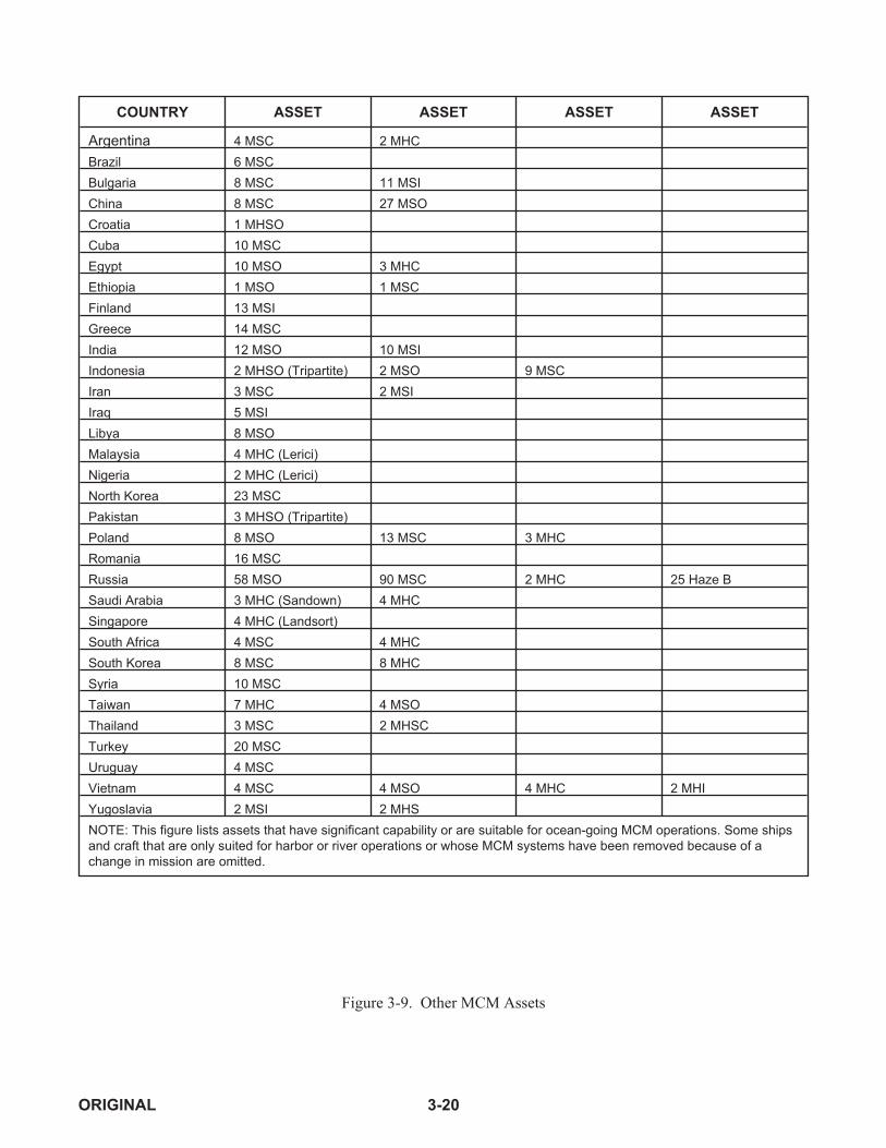
ORIGINAL 3-20
COUNTRY ASSET ASSET ASSET ASSET
Argentina 4 MSC 2 MHC
Brazil 6 MSC
Bulgaria 8 MSC 11 MSI
China 8 MSC 27 MSO
Croatia 1 MHSO
Cuba 10 MSC
Egypt 10 MSO 3 MHC
Ethiopia 1 MSO 1 MSC
Finland 13 MSI
Greece 14 MSC
India 12 MSO 10 MSI
Indonesia 2 MHSO (Tripartite) 2 MSO 9 MSC
Iran 3 MSC 2 MSI
Iraq 5 MSI
Libya 8 MSO
Malaysia 4 MHC (Lerici)
Nigeria 2 MHC (Lerici)
North Korea 23 MSC
Pakistan 3 MHSO (Tripartite)
Poland 8 MSO 13 MSC 3 MHC
Romania 16 MSC
Russia 58 MSO 90 MSC 2 MHC 25 Haze B
Saudi Arabia 3 MHC (Sandown) 4 MHC
Singapore 4 MHC (Landsort)
South Africa 4 MSC 4 MHC
South Korea 8 MSC 8 MHC
Syria 10 MSC
Taiwan 7 MHC 4 MSO
Thailand 3 MSC 2 MHSC
Turkey 20 MSC
Uruguay 4 MSC
Vietnam 4 MSC 4 MSO 4 MHC 2 MHI
Yugoslavia 2 MSI 2 MHS
NOTE: This figure lists assets that have significant capability or are suitable for ocean-going MCM operations. Some ships
and craft that are only suited for harbor or river operations or whose MCM systems have been removed because of a
change in mission are omitted.
Figure 3-9. Other MCM Assets
3.8 AMPHIBIOUS MINECOUNTERMEASURES OPERATIONS
Minefields and obstacles mixed with the minefieldform an integral part of the antilanding defenses thatmust be overcome for a successful amphibious landing.The mission of MCM forces is to prevent the delay ordisruption of amphibious operations due to enemy min-ing. MCM in support of amphibious operations is fre-quently referred to as SWMCM because of the relativeshallowness of the depth zones involved. The littoralarea is divided into three depth zones based on varia-tions in environment, types of mines encountered, andlimitations of asset capability.
The SZ is that area between the high water mark orzero feet out to 10 feet. In this area, any significantwave action will make a swimmer unable to maintaincontrol and conduct a safe search for mines. The minesthat might be found here include ground contact mines,ground influence mines, ground pressure plate mines,ground tilt rod mines, moored contact, moored influ-ence, and anti-invasion mines. Additionally, mixedwith the mines may be obstacles that can complicate themine clearance problem.
The VSW zone is between 10 and 40 feet deep.Mines found in this zone may include ground ormoored contact mines, ground or moored single influ-ence mines, ground multiple influence mines, andground tilt rod mines. Obstacles may also be foundhere, though probably not as many as in the SZ.
The SW zone covers the 40- to 200-foot area.Moored contact mines and ground or moored singleand multiple influence mines will be found here. Obsta-cles are still possible but less likely because they arehighly dependent on the severe tidal variations.
To avoid causing a delay in the amphibious landing,MCM must be performed prior to the assault to clearchannels for landing craft and transport ships to ap-proach the beach. During this time, MCM forces mustremain undetected if the element of surprise is to bemaintained. Problems which must be overcome includethe following:
1. AMCM and SMCM forces are not capable ofundetected operations where any radar systemor visual watch is maintained.
2. AMCM is limited to daylight operations.
3. SMCM can do exploratory mine hunting at nightbut is detectable on radar and is defenseless.
4. MMS detachments could be used in exploratory/marking operations at night but are also detect-able and defenseless.
Current tactics used in support of amphibious opera-tions are found in SWDG TACMEMO 6022-1-95/OH1-17. Breach in stride, the breakthrough of an enemyminefield during an amphibious assault, is one of themethods and takes advantage of surprise and initiativeto get through the obstruction with minimal loss of mo-mentum. It maintains the momentum of the attack bydenying the enemy time to mass forces to cover the ob-stacle or minefield. Subordinate units should be capa-ble of independent breaching operations to accomplishthe mission against weak defense, light defense, simplebarriers, or unclear situations.
The NSW force conducts covert beach reconnais-sance, which verifies that a mine threat is present. NSWis responsible for clearance of mines from 21 feet to thesurf zone and may mark mines during reconnaissancefor later planting of neutralization charges or plantcharges during reconnaissance. To maintain covertnessas long as possible, detonation of neutralization chargesand charges on other obstacles will likely occur at thebeginning of the assault. If there is any significant waveaction, NSW swimmers are not able to safely and co-vertly operate in the surf zone, so even if total successcould be attained in other areas, some mines may stillbe left where the concentrations of mines and obstaclesare the heaviest.
If surprise is sacrificed and overt MCM is commencedprior to the assault using SMCM and AMCM forces indaylight, ships, helicopters, and EOD boats are vulnerableto any hostile fire from the beach. Heavy losses can be ex-pected if all types of fire from the beach cannot be sup-pressed. If no preassault phase MCM is conducted otherthan NSW reconnaissance, it is unlikely the MCM forcewill be able to make a significant reduction in the threatwithout delaying the assault. MCM is a time-consumingprocess because of the slow pace at which sweeping andhunting are conducted. Even a single-pass mechanicalsweep to cut moored mines is not quick because any cutmines must be prosecuted individually.
The varying depth environment forces a division ofresponsibility by depth capability. NSW is the onlyforce that can operate in the SZ. AMCM systems (thefastest coverage rate of all systems) are not as effectivein the SZ, but depending upon equipment used, theycan operate as shallow as 8 feet. If any obstacles are en-countered in this area, natural or manmade, gear lossesmay be a critical factor. From 30 feet and deeper,AMCM and SMCM can both be effective.
3-21 ORIGINAL
Mutual interference occurs when swimmers/diversare working directly adjacent to AMCM or SMCMconducting influence sweeping. Consequently theseoperations must occur at different times or have a care-fully orchestrated separation distance.
When mines are present, waiting until after the as-sault for MCM probably would result in unacceptablelosses. Continuing MCM after the assault will be neces-sary to expand cleared areas, increase clearance per-centages, and counter any delay arm mines.
Coordination of MCM with other warfare areas dur-ing all phases is very important; however, the MCMchain of command may vary according to the phase ofthe operation. The MCM commander may be subordi-nate to the following:
1. The area commander, if MCM forces are in thearea before the ATF arrives. It is also likelysome forces will have to continue to support thearea commander.
2. The CATF, who has the overall responsibilityfor MCM in the AOA. The CATF may delegatethe conduct of MCM to the MCM commanderand may assign the MCM force to the advanceforce commander.
3. The advance force commander may have con-trol of MCM forces, particularly for thepreassault phase. Careful liaison and coordina-tion are required during planning to ensure theMCM commander can fully support the ATFcommander during assault-phase MCM.
3.9 SUBMARINE MINE COUNTERMEASURESOPERATIONS
In most roles, the submarine is an independent operatorcounting on stealth to protect it from most threats. How-ever, once in position, the mine is even more stealthy thanthe submarine and can easily target any passing within itsdetection envelope. Consequently, submariners have de-veloped systems and tactics to detect and avoid mines.Some submarine sonars originally designed to detect icehave proven capable of detecting mines moored in the wa-ter column. Based on experience with these sonars, newsubmarine sonar systems have been developed with thenecessary transducer arrays to permit searching for anddetecting mines. However, submarines are not MCMplatforms and should not be expected to transit mined wa-ters on purpose. Nevertheless, they can be used to con-duct reconnaissance ahead of a battle group to determinewhether a clear channel exists. They can also transit to
forward operating areas without requiring supportingMCM forces to determine a clear channel.
Since submarines are capable of operating under theice in polar waters, they may also be faced with mineseither placed under the ice or laid in an area that hassince iced over. This cannot be addressed by surface orairborne MCM forces and must therefore be dealt withby the submarine on its own. A discussion of equip-ment and tactics for this situation can be found in theNWP 3-21 (formerly NWP 70) series.
3.10 RIVERINE MINE COUNTERMEASURESOPERATIONS
Riverine MCM operations include all MCM opera-tions in rivers, canals, and lakes that are significant inlandtraffic ways. The water may be saline, brackish, or fresh-water and is assumed to have a considerably lower electri-cal conductivity than seawater. There may be a higherconcentration of debris on the bottom; mud or silt bottomsare likely to be the norm. These environmental conditionscombined with the limited depths and maneuvering roomin many riverine scenarios make most current MCM plat-forms and systems poorly suited for these operations.
The last significant riverine MCM operation conductedby U.S. Navy forces occurred in the Vietnam Conflict.Although all of the specialized systems and platformsused during that period have been retired, the designs andprocedures for employment are still available in archivesand could be recalled for use if necessary.
Of the SMCM platforms and systems in current use,some would be employed in riverine MCM operationsdespite limited suitability. The MCM 1 and MHC 51Class ships are limited in utility because of size and lim-iting depths: the navigation drafts of 12.2 feet and 9.2feet, respectively, prevent employment in the shallowriver environment except where deep channels exist orhave been created. Additionally, the MCM systems in-stalled are all designed to operate in water greater than30 feet deep, and the sonars require a minimum waterdepth in the 50-foot range for deployment. The SAMsystem would be far more suitable for riverine opera-tions, but there are only two SAM craft in the inventory.
AMCM helicopters could be employed in riverineoperations, provided the surrounding geography pro-vides room for maneuver. River banks shrouded withtall or overhanging trees could cause severe limitations.The AMCM shallow-water sweep systems (MOP andRattlebars) would be effective in riverine operations,but the AN/AQS-14 Sonar, Mk-104, and Mk-105Sweep Systems would probably not be usable.
ORIGINAL 3-22
EODMCM should be fully functional in riverine op-erations, although poor water clarity might hamperdiver operations. EOD MMS systems would be not beemployable since they require a seawater environment.
A description of the mine threat and MCM systemsemployed in riverine operations can be found in the 1992Mine Warfare Summary, published by the Mine WarfareBranch of the Office of the Chief of Naval Operations.
3.11 DEPLOYMENT OF MINECOUNTERMEASURES FORCES
MCM assets do not participate in normal rotationaldeployment cycles like other combatant forces. Theforce levels and ship characteristics necessary to main-tain a continuous presence in overseas theaters do notexist in the MCM force. The necessary endurance andself-sufficiency for these cycles run contrary to the de-sign requirement to minimize the influence signature ofMCM platforms. Therefore, when an OPLAN calls forMCM forces, they must be transported to the area andprovided the basing/support that meets their somewhatunique requirements. Transportation and support re-quirements vary by platform and unit type, but all mustbe included in the OPLAN TPFDL, and sufficient pri-ority must be assigned to ensure that lack of MCMforces will not unduly hinder other force operations.
Prior to deploying an MCM force to an area whereno recent operations have been conducted, a site surveyshould be conducted. The support requirements forMCM forces are sufficiently different from other navalforces to justify an advance party visit to the area fromwhich operations will be supported. The advance partycan conduct briefings of support personnel and surveyship mooring facilities or aircraft landing, parking, andmaintenance areas to determine whether the existingequipment is suitable to support the MCM force. If ad-ditional arrangements need to be made, they can bestarted prior to arrival of the MCM force, and in somecases, the advance party will be able to determinewhether additional equipment needs to be transportedfrom the home base or whether some equipment may beleft behind. Appendix B of NWP 3-15.1 (formerly NWP27-1) contains a contingency plan survey list. More de-tailed lists are generally held by the MCM Squadronstaffs, AMCM Squadrons, and EOD Mobile Units.
3.11.1 Surface Mine Countermeasures Forces.Surface MCM ships can be moved to the area of opera-tions in three ways: self-transit, towing, or heavy liftship. The following characteristics may be advantagesor disadvantages, depending on the scenario and dis-tance to be deployed:
1. Self-transit
a. Maximum average SOA is 8 knots.
b. Builds engine wear on nonmagnetic engines.
c. Ships require refueling every 3 to 4 days usingastern rig.
d. Must avoid heavy weather.
e. Maintenance period required on arrival forPMS/voyage repairs.
f. The full crew rides the ship.
g. Escort desired for long transits and to providerefueling services.
h. If escorted by MCS, the MCM Commander,AMCM, and EODMCM can also beembarked.
i. The escort may carry spare parts, engines, andsweep gear.
2. Towing
a. Depends on availability of a tow ship.
b. The tow speed may be less than self-transitspeed.
c. Does not cause wear on engines.
d. Heavy weather may damage or delay tow.
e. May require maintenance period at end of towfor PMS.
f. Crew can ride the ships, but training en routeis limited.
g. Tow ship may not be able to transport spareparts, engines, and sweep gear.
3. Heavy Lift Ship
a. Depends on lift ship availability.
b. Only a few lift ships can carry three or fourMCM ships.
c. Some lift ships cannot transit the PanamaCanal.
3-23 ORIGINAL
d. Requires deep berth (60 feet) for onload andoffload with calm weather.
e. Onload requires about seven days, andoffload requires about three days.
f. Most lift ships are capable of a 12-knot SOA.
g. Results in no engine wear, but there are poten-tial power train alignment problems fromdocking.
h. Lift ship is not as susceptible to delay byheavy weather.
i. Crew support may not be available on liftship.
j. Lift ship can usually carry containers of spareparts, sweep equipment, C4I vans, andEODMCM equipment, etc.
k. Requires significant additional funding.
If SMCM ships are deployed by towing or heavylift, any portion of the crews who do not ride the shipscan be given additional training and briefings to main-tain or sharpen their skills for the anticipated opera-tions. It may be feasible to assign another MCM orMHC as training ship and conduct refresher trainingunderway, prior to the crews’ rejoining the ship.
The crews should arrive in theater just prior to the liftor tow ship’s arrival at the destination if messing andberthing can be provided. Otherwise it will be neces-sary to coordinate their arrival with the offload date sothat they will be able to embark the ship immediately.
Once in the area of operations, SMCM forces requiresome unique support. The hulls of U.S. SMCM ships areconstructed of wood with a GRP sheath (MCM Class) orsolid GRP (MHC Class). Mooring facilities for the shipsneed to be equipped with Yokohama-style fenders to pro-tect the hull from direct contact with the pier structure.Additionally, since these are relatively small ships, theyfrequently require some additional effort to rig browswhen placed at commercial ship docking facilities.
Other than mooring support, the SMCM ships re-quire frequent replenishment of supplies, often insmaller quantities than most ship chandlers are used todealing with, and they have little crew support features.These ships have no disbursing, ship’s store, barber, ordental facilities, and these services need to be providedby a shore base or other ship when not in company withthe MCS or other assigned support ship. Additional lo-gistics support requirements are discussed in NWP
3-15.1 and NWP 3-15.11 (formerly NWP 27-1 andNWP 27-2).
For long-term presence of MCM ships (forward de-ployment) or an operation longer than 6 months, MCMand MHC ship crews may be rotated between CONUShulls and the deployed hulls to reduce the impact onPERSTEMPO. Since the number of MCM and MHCships available and the time required for transiting toand from a forward base make normal rotational de-ployments impractical, crew swapping may be used toprovide the personnel relief from the arduous lifestylewhen deployed on board a small ship
3.11.2 Airborne Mine CountermeasuresForces. The AMCM mission includes a quick re-sponse readiness posture, being able to rapidly deployworldwide via air or surface lift, and an ability to con-duct AMCM operations from fixed land bases, aircraftcarriers, and air-capable amphibious ships.
AMCM can transit by assisted self-lift, airlift, or sur-face lift. For short-range deployments, MH-53Es can flycross-country with some support personnel and MCMequipment on board. Remaining support equipment andpersonnel can be carried by ground transportation orC-130/C-141 airlifters. Transportation of all support equip-ment and 90-day packup by ground requires 20 to 30 trailertrucks, depending on the sweep systems to be carried.
For longer range deployments, AMCM can be trans-ported by C-5A/C-141 airlifters. Approximately eightC-5As and nine C-141s are required to deploy an8-plane squadron. The squadron has a computerizedLoadout Support System program to prepare the loadplan which interfaces with the Air Force ComputerAided Load Manifesting program.
Surface deployment of AMCM requires a large-deckaviation-capable ship. CV, LHA, LHD, MCS, and LPDtypes are all capable of transporting and supportingAMCM operations. Operation from a CV/CVN dis-places some of the air wing and requires significantmodification of the normal flight operations routine.Operation from an LHD or LHA in conjunction withsome Marine air assets creates less impact than on aCV, but still requires significant coordination. The LPHhas been the most frequently used and suitable platform,but except for a few gunships and SAR/utility aircraft,the Marine air combat element is displaced. Althoughthe LPH classes are being decommissioned, LPH 12 isbeing converted and will remain in commission as MCS12. An LPD can accommodate only three aircraft,thereby limiting operations due to number of deck spots.It also provides no maintenance support (such as AIMD
ORIGINAL 3-24
or hangar deck maintenance area) and cannot accom-modate utility aircraft. LSDs are unsuitable due to decklimits and lack of space. All platforms require 3 to 5days on-load to properly stow equipment.
Whatever the method of deployment, the normal de-ployment package includes eight MH-53E helicopters,Mk 103/104/105 Minesweeping Systems, AN/AQS-14Sonars, AN/ALQ-141 Countermeasures Sets, groundsupport and maintenance equipment, a 90-day packup(205 cubic meters, 2,650 kilograms), Rigid Hull Inflat-able Boats for equipment launch and recovery, and ap-proximately 450 personnel.
Logistics support required for AMCM deployed op-erations is similar for shipboard or shore operations.Requirements are summarized below, but more de-tailed requirements can be found in NWP 3-15.12 (for-merly NWP 27-3).
1. Normal aviation support facilities aboard ship orashore (runways, parking apron, fuel trucks, etc.)
2. Accommodation for 90-day packup: spare air-craft parts for 90 days (which weigh 72,000pounds and occupy 7,000 square feet), most ofwhich require covered storage
3. Space (4,120 square feet) for office and work-center
4. Berthing and messing for 450 personnel
5. Fuel (22,000 gallons of JP-5 will be used per dayif each aircraft flies a single hop), as well as die-sel fuel for RHIBs
6. Freshwater wash capabilities for aircraft andsweep systems
7. MK-105 sled launch and recovery require craneif ship is not well deck-equipped, or boat rampfor shore site
8. RHIB boats for sled operations require crane/davitfor launch from trailers or pier berthing/parkingarea for shore operations
9. AMCM packup, which includes four MMFs setup to conduct equipment maintenance
10. Ground support equipment, including forklifts,mobile power units, hydraulic test stands, towtractors, workstands, cranes, nitrogen carts, etc.If on board ship, many of these items will be pro-vided by the ship.
For extended operations, especially when 90-daypackup spares are expended, a dependable logisticspipeline is needed. Movement of engines, transmis-sions, and rotor blades to and from CONUS refurbish-ment facilities must be accomplished.
3.11.3 Underwater Mine CountermeasuresForces. The following paragraphs discuss briefly thelogistics of deploying UMCM forces. Additional detailmay be found in NWP 3-15.14 (formerly NWP 27-8).
3.11.3.1 Explosive Ordnance Disposed MineCountermeasures. EODMCM personnel can de-ploy for operations in conjunction with surface MCMvessels, AMCM aircraft, or independently from bothshore-based and shipboard facilities. EODMCM de-tachments are designed for short notice deploymentsand can operate for approximately 30 days without re-supply (except for water, food, and fuel). A certified de-tachment can be deployed on very short notice.
For short range overland deployments, all EOD equip-ment is capable of being transported by three to fourtrucks that can tow 8,000 pound trailers. For long transitstrailers may be loaded onto flatbed tractor trailer rigs. Foroverseas surface lift, all equipment may be embarked onboard most large class ships. A detachment can embarkon an MCM ship but will be able to carry only a limitedoperational equipment loadout. For long surface transits,it is preferred to deploy the EOD detachment on a largership and then transfer them to the MCM ship once in theoperating area. For airlift, the entire EODMCM detach-ment can be loaded on various airlifter combinations. Re-fer to TPFDD documents for specific data.
One EODMCM Detachment consists of eight person-nel, and the equipment to be transported may include:
1. FADL — This is a 20’ x 8’ x 8’ trailer that storesall dive equipment and provides an O2 clean areafor diving equipment maintenance.
2. FARC — This is a portable recompressionchamber with self-contained support systems(Life Support Skid), portable power generator,and three-man support crew.
3. RHIB — Each detachment has one 24-foot rigidhull inflatable boat for diving support operationsand transport of divers to and from the dive area.The boat is equipped with a trailer for storage.
4. Inflatable boat — Each detachment uses an inflatablerubber boat (Mk-5 Zodiac) with engines suitable for
3-25 ORIGINAL

dive operations on mines. The boat can beplaced on a trailer or deflated for transportation..
Logistics support required for deployed operations (de-scribed in detail in NWP 3-15.14) is summarized below:
1. Land transportation — If stationed ashore, thedetachment will require trucks (which it maybring itself) to tow boat and equipment trailersand to transfer personnel.
2. Boat operations — If ashore, a small craft pierspace or a boat ramp is required to support oper-ation of both craft. If afloat, a crane or davit tolaunch and recover boats is required. Gasolinefor boat engines is needed.
3. Recompression chamber — Unless supportedby a local, certified recompression chamber, ap-proximately 350 square feet is required to set upthe FARC. The FARC can be self-supporting for30 days except for diesel fuel.
4. Diving locker — The FADL requires about 200square feet of deck space, a freshwater supply,and 3-phase, 60-Hz power.
5. Explosive storage — The detachment has a por-table magazine for which 450 cubic feet of ex-plosive storage is required.
6. Compressed gas storage — Aviation grade O2
and a helium oxygen mix are required.
7. Communications — The detachment requiressupport to transmit and receive naval messagetraffic and may require support for obtainingkeying material for secure voice radios.
8. Berthing and messing for eight to 12 persons.
9. Office/work space: Except for short-term opera-tions, a covered, climate-controlled office andwork space is necessary.
3.11.3.2 Mine Mammal System. MMS can bedeployed to operate independently or as an integratedforce with SMCM and AMCM. Certain conditionsmust exist in the area of operations for MMS.
MMS requires a safe base of operations on a friendlyshore or a support ship with sufficient space and weightcapacity to embark dolphin tanks, support systems, andpersonnel. The minimum water depth at a shore stagingarea must be 2.5 meters. Water temperature must remainbetween 42 and 91 °F during the period the dolphins are
in the area. There must be no significant environmentalpollution, and water salinity must be at least 20 partsper thousand. If these conditions do not exist, the area isunsuitable for deployment of MMS.
Prior to deployment of MMS, a site survey is neces-sary to determine the suitability of the area and supportavailable. The survey takes from 1 to 3 days and in-cludes water chemical sampling, facility inspection,evaluation of the OPAREA for MMS, and logisticssupport arrangements.
Short-distance deployments of EOD MMS MIL-VANs and SEABEE shelters can be accomplished bytruck. Boats require three to four trucks with an800-pound towing capacity. The dolphins may bemoved on trucks; however, it is preferable to transportthem via cargo helicopters (internal load) to minimizetransport time. Long-distance deployments requiresealift or airlift. Maximum demonstrated sealift transittime is currently 11 days. Long-term embarkation on thelift ship without the opportunity for swimming in theopen sea may affect the health and training of the mam-mals. If a long-range surface lift is envisioned, airlift ofthe mammals to the area of operations following surfaceship arrival is preferred to preserve their operability. Forairlift, the entire EOD MMS detachment can be trans-ported on various aircraft combinations listed in theTPFDD. Staggered arrival of transport aircraft permitsadvance personnel to assemble support equipment priorto arrival of the MMS. Regardless of deploymentmethod, once on scene, the mammals may require sev-eral days to acclimate to the new environment.
In addition to the limiting conditions mentioned be-fore, deployed MMS requires the following:
1. A pier, causeway, quay wall, ship, or other sta-ble platform to secure staging pens
2. 190 square meters of level ground for MILVANand support equipment
3. A crane capable of lifting and positioningMILVAN and support equipment (15-toncapacity)
4. A freshwater supply
5. 220/110-volt, 60-Hz AC, 100-amp electricalservice at the staging area
6. A suitable area for storage of Class A explosives
7. Messing and accommodations for up to 70 per-sonnel (Mk 4 MMS has 24, Mk 7 MMS has 36, and
ORIGINAL 3-26
other personnel provide command element andmaintenance support)
8. Communications support for transmission andreception of message traffic and periodic securevoice radio encryption update.
An EOD MMS detachment deploys with sufficient as-sets to support 15 days of sustained operations, with theexception of MOGAS. Mk 4 and Mk 7 MMS detach-ments conducting simultaneous operations may requireup to 500 gallons of MOGAS per day. A 15-day replen-ishment will require the following:
1. 100 kg (240 pounds) of frozen fish per day (iffull complement of both Mk 4 and Mk 7 aredeployed)
2. Food for personnel if operating from a remote site
3. Explosives and minefield markers
4. Dry cell batteries for radios, electronic search,and navigation equipment
5. Spare parts as depleted by maintenance activities
6. 55 gallons of 2-cycle outboard motor oil.
Emergency support for MEDEVAC should beplanned due to the inherent dangers of diving andMCM operations. Lon- term operations may requireadditional maintenance support for equipment repairs.
3.11.3.3 Navy Special Warfare. NSW forces areembarked with an ARG and, as directed by CATF, havethe capability to conduct MCM operations in relation toan amphibious landing. They would not be likely to de-ploy for MCM independent of an ARG. Essentially allsupport for NSW would be provided from within theARG, although the MCS 12 may be called on for somesupport. Berthing, messing, and transportation of someequipment is within the capability of the MCS. The NSWcombat rubber raiding craft can be launched and recov-ered from the MCS, and diving support facilities such asbottled gases and a recompression chamber are available.
3.11.4 Mine Countermeasures Staff. One of thefirst actions that should be taken when considering de-ployment of MCM forces (in addition to a site survey) isthe deployment of one or more Staff Liaison Officersfrom the MCM squadron staffs. The primary purpose ofthese officers is to maintain the communications flowbetween a task group/force commander or theater com-mander and the MCM commander. They can be instru-mental in making the initial decisions on which forces
are needed and laying the ground work for deploymentof other assets.
The MCM commander and staff can be deployed byairlift independent of other forces or by sea embarkedon the MCM support ship. MCS 12 is specially config-ured to support the MCM commander and should beused whenever possible. The staff consists of between15 and 20 people (depending on the situation) with ad-ministrative support equipment and supplies packed incruise boxes. They can be deployed on very short no-tice, but should not deploy until some support facilitiesare available in theater.
To effectively plan and control MCM operations, theMCM commander requires a dedicated command cen-ter with C4I capabilities. The MCM and MHC classships are not equipped to support a staff; they have noberthing, insufficient communications, and no sparespace in CIC to be used by a staff. If an afloat unit that isoutfitted as a flagship cannot be made available to theMCM commander, it is possible for him to be set up inan ashore command center. Minimum basic require-ments are as follows:
1. Adequate secure space for six to eight personnel(two to three maintaining a 24-hour watch)
2. Status boards and space for plotting on hydro-graphic charts (chart table or large flat table)
3. Communication suite to support sending and re-ceiving message traffic, as well as maintainingsecure voice and data communications withother command authorities and the MCM forces
4. 110-volt power source for operation of desk topcomputers
5. Messing and berthing for the deployed personnel.
If no established command center exists ashore toaccommodate the MCM commander, an alternative isto use the COMINEWARCOM deployable C4I van.This new system is intended to be a self-contained com-mand center that can be embarked on a ship or set upashore. It is equipped with all necessary communica-tions and tactical data systems to support the MCMcommander. The characteristics of the C4i van were notavailable for inclusion in this publication, but they canbe obtained by contacting COMINEWARCOM.
Although far less desirable, another option is to usean MIUW command van, which can fulfill the mini-mum communications requirements.
3-27 ORIGINAL
3.12 INTERFACE WITH THE ENVIRONMENT
3.12.1 General/Introduction. Mine warfare is thephase of littoral warfare most sensitive to environmen-tal considerations. In strategic, tactical, and technicalplanning for both mining and MCM, the environmentplays the dominant role. Minelaying missions will beconducted only if environmental conditions are favor-able for delivery and weapon effectiveness after the lay.Mine weapon systems and components (mine cases,mine sensors, and target signals, for example) are all af-fected in significant ways by myriad environmentalfactors. Similarly, the fundamental decision in MCM (toconduct exploratory and reconnaissance operations todetermine the presence or absence of mines, the extent ofany mine fields present, and which mine hunting, sweep-ing, avoidance, or combination of these tactics and tech-niques can be effectively employed) is environmental innature. A matrix summary of environmental factors af-fecting MCM is provided in Figure 3-10.
3.12.2 Environmental Factors. Many environ-mental factors affect mine, amphibious, and special war-fare, and, because of the land/sea interface, they are morecomplex in the coastal/littoral areas than the open ocean.
Environmental factors affecting littoral warfare willbe discussed in seven broad areas: oceanographic, me-teorological, biological, acoustic, hydrographic andgeophysical, and anthropogenic (manmade).
3.12.2.1 Oceanographic. Considerations uniqueto or magnified in the coastal oceanographic area aretides, tidal currents, surf conditions, wave height anddirection, turbidity (and associated absorption of dis-solved and particulate matter), and water visibility(both vertical and horizontal). Salinity (conductivity),water temperature, and temperature gradient as func-tions of depth should be considered in the evaluation ofsonar performance.
3.12.2.2 Meteorological. The atmospheric ele-ments are magnified in the coastal environment. Windspeed and direction, and therefore wave height, direc-tion, and shape, are affected by diurnal effects (land andsea breezes). Ambient light available is affected by par-ticulate matter such as smoke and dust. Ship safety maybe affected by limited options for storm evasion.Weather in general, unless ideal conditions are encoun-tered, will figure most significantly in the time requiredto conduct enabling mine warfare operations.
3.12.2.3 Biological. Marine life, from microscopicorganisms to large marine mammals, plants, fish, mustbe considered in the planning and execution of littoral
warfare operations because of their special impact. Am-bient noise, acoustic and optical scattering, false targets,biofouling, and the effects of seaweed, kelp, coral reefs,and coral heads are examples of marine life effects. Haz-ardous animals such as sea snakes, sharks, and jellyfish(e.g., the Portuguese man-of-war), are certainly taken se-riously and considered carefully by divers.
3.12.2.4 Acoustic. The decision to sweep is basedlargely on the axiom, “mine hunt where and when youcan; mine sweep when and where you must.” Whilethere are some limited applications of nonacousticmine hunting, acoustics are the primary medium for thedetection and classification of minelike objects. Thesound velocity profile is extremely important in the litto-ral minehunting problem. Scattering, reverberations, lay-ering, ambient noise, and signal energy transmission lossdetermine in large measure minehunting effectiveness, ef-ficiency, and safety. The minehunting measure of effec-tiveness will be used in the decision to hunt or sweep.
3.12.2.5 Hydrography, Bathymetry, and Geo-physics. This combined category encompasses all theproperties related to the bottom, or sea bed, and includessuch factors as ambient magnetic background and anoma-lies, sediment (gases, gradient, conductivity, and stabil-ity), and pressure wave transmission. The hydrographicconcerns of beach slope, topography, and depth range willbe of primary importance to the amphibious planner, butthe enabling mine warfare commander will consider bot-tom conditions: type, roughness, strength and stability,and clutter (which includes both magnetic and acoustic).
3.12.2.6 Anthropogenic. These effects in the litto-ral environment entail manmade influences on mineand MCM systems. The human influence in the regionsincludes different types of pollution, over-fishing, thecreation of artificial reefs and fishing havens, and mili-tary operations in which ordnance and debris are leftbehind. Coastal merchant and fishing ships create noiseand can produce sediment upwelling. Shipwrecks,trash, fishing traps, and well-heads are all manmade in-fluences affecting littoral warfare operations.
The section that follows will discuss briefly some ofthe effects of these influences on mine warfare weap-ons and systems.
3.12.3 Environmental Effects on Mine WarfareWeapons, Systems, and Decisions. MIW plan-ners and tacticians will know and take into consider-ation the problems facing the enemy miner, includingthe environment. The impact of the environment onmines as discussed in Chapter 2 is the starting point forthe MCM effort.
ORIGINAL 3-28
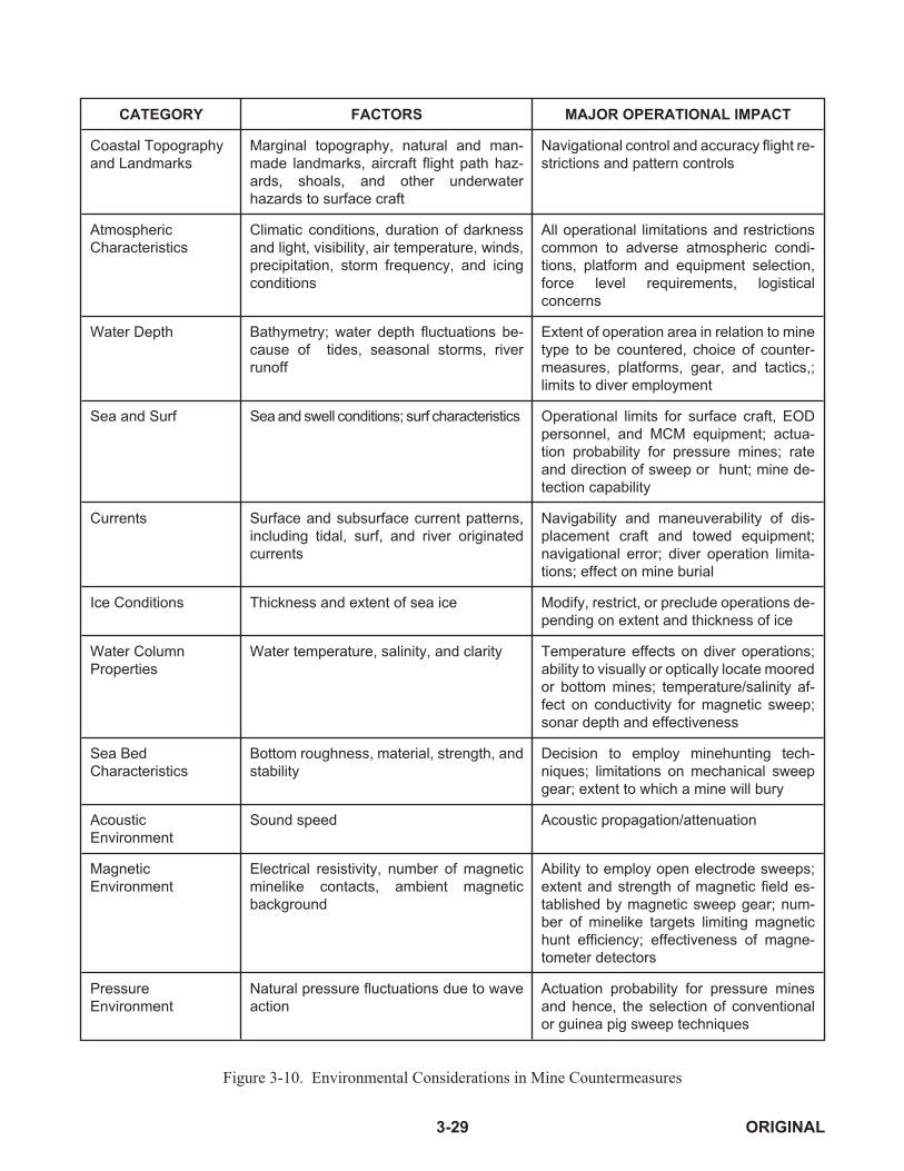
3-29 ORIGINAL
CATEGORY FACTORS MAJOR OPERATIONAL IMPACT
Coastal Topography
and Landmarks
Marginal topography, natural and man-
made landmarks, aircraft flight path haz-
ards, shoals, and other underwater
hazards to surface craft
Navigational control and accuracy flight re-
strictions and pattern controls
Atmospheric
Characteristics
Climatic conditions, duration of darkness
and light, visibility, air temperature, winds,
precipitation, storm frequency, and icing
conditions
All operational limitations and restrictions
common to adverse atmospheric condi-
tions, platform and equipment selection,
force level requirements, logistical
concerns
Water Depth Bathymetry; water depth fluctuations be-
cause of tides, seasonal storms, river
runoff
Extent of operation area in relation to mine
type to be countered, choice of counter-
measures, platforms, gear, and tactics,;
limits to diver employment
Sea and Surf Sea and swell conditions; surf characteristics Operational limits for surface craft, EOD
personnel, and MCM equipment; actua-
tion probability for pressure mines; rate
and direction of sweep or hunt; mine de-
tection capability
Currents Surface and subsurface current patterns,
including tidal, surf, and river originated
currents
Navigability and maneuverability of dis-
placement craft and towed equipment;
navigational error; diver operation limita-
tions; effect on mine burial
Ice Conditions Thickness and extent of sea ice Modify, restrict, or preclude operations de-
pending on extent and thickness of ice
Water Column
Properties
Water temperature, salinity, and clarity Temperature effects on diver operations;
ability to visually or optically locate moored
or bottom mines; temperature/salinity af-
fect on conductivity for magnetic sweep;
sonar depth and effectiveness
Sea Bed
Characteristics
Bottom roughness, material, strength, and
stability
Decision to employ minehunting tech-
niques; limitations on mechanical sweep
gear; extent to which a mine will bury
Acoustic
Environment
Sound speed Acoustic propagation/attenuation
Magnetic
Environment
Electrical resistivity, number of magnetic
minelike contacts, ambient magnetic
background
Ability to employ open electrode sweeps;
extent and strength of magnetic field es-
tablished by magnetic sweep gear; num-
ber of minelike targets limiting magnetic
hunt efficiency; effectiveness of magne-
tometer detectors
Pressure
Environment
Natural pressure fluctuations due to wave
action
Actuation probability for pressure mines
and hence, the selection of conventional
or guinea pig sweep techniques
Figure 3-10. Environmental Considerations in Mine Countermeasures
Environmental factors affecting the planning and ex-ecution of MCM operations will be discussed in twocategories: stable and transient characteristics.
1. Stable characteristics, such as bathymetry and to-pography (in short, valid data from prior surveys).
2. Transient characteristics, such as the thermal prop-erties of the water column and meteorological con-ditions (in short, information obtained in situ).
3.12.3.1 Stable Environmental CharacteristicsAffecting Minesweeping Operations.
3.12.3.1.1 Water Depth. The sweeping techniquesused are often determined by water depth. Ships rarelyoperate in less than 10 meters of water, but they are wellsuited for deep ocean sweeping. Helicopters andnon-displacement craft are better suited for shallowwater sweeping.
3.12.3.1.2 Bottom Topography. Variations of bot-tom gradient, as well as holes, ridges, and peaks, willdictate special planning and handling of sweep gear.Track orientation and depth segmenting must be con-sidered to increase sweep efficiency and reduce riskof damage to equipment. Further, a complex bottomtopography may require both sweeping and hunting toreach the desired clearance level.
3.12.3.1.3 Bottom Composition. Mine burial willbe determined by various factors, including bottomstrength, composition, and stability. Burial will affectboth the miner and the countermeasures effort (sensitivi-ties of acoustics and pressure mechanisms may be less-ened by burial). The potential for mine burial figuressignificantly in the decision whether to sweep or to hunt.
3.12.3.1.4 Underwater Obstacles. Wrecks andother anthropogenic objects restrict the depth and per-haps even the use of sweeping equipment. In aggravatedsituations, area avoidance may be the only viable option.
3.12.3.1.5 Geography. Prominent landmarks andspecial coastal features are of use in both planning andconducting MCM operations because these characteris-tics may affect navigation and maneuvers.
3.12.3.1.6 Magnetic Minesweeping Environ-ment. While fairly complex in theory and planning,there are two principal elements to consider in magneticmine sweeping: the electrical conductivity of water andthe depth of water. Electrical conductivity will dictatethe use of open- or closed-loop sweeps. Water depth isthe only factor affecting the performance of closedsweeps against all magnetic mines and that of open
sweeps against the vertical component of magneticmines. Seawater conductivity affects the amount ofcurrent that can be used in the open-loop sweeps.
3.12.3.1.7 Acoustic Minesweeping Environ-ment. The most important factor in acoustic sweeps isthe sound pressure level loss in transmission of acousticsignals. Transmission loss is a function of sweep-to-minedistance, frequency, water and mine case depths, and bot-tom geology. The exact determination of transmission lossis complex; for practical reasons average transmissionlosses are tabulated as a function of depth and frequency.
3.12.3.2 Transient Environmental Character-istics Affecting Minesweeping Operations
3.12.3.2.1 Tides and Tidal Currents. Planningand conducting MCM operations with respect to therise and fall of the tide is a straightforward navigationproblem. Tides will affect the case depth of somemoored mines if near the surface. The effect of tidalstreams and currents poses more complex problems, in-cluding mine dip. Currents can cause navigational, ma-neuvering, and sweep streaming problems and must bedealt with carefully. Displacement minesweepers musttake current information into account when operatingwhere pressure mines may be present since currentmust be figured in the ship’s speed over the ground.
3.12.3.2.2 Climate and Weather. Rain, fog, seastate, and smoke all affect mine-sweeping operations.The streaming of minesweeping equipment, both air-borne and surface, is extremely hazardous, especiallyas the sea state and/or turbulence increase.
3.12.3.2.3 Wind. Wind is one of the most signifi-cant environmental factors for all MCM operations be-cause it drives sea state, affects current, inducesmaneuvering (and therefore navigational) problems,and limits helicopter operations. Wind combined withlow air temperature produces wind chill factors thatmake exposed sweeper crews vulnerable to cold and fa-tigue, which in turn can limit crew on cycle time andlengthen the time required for mine clearing operations.
3.12.3.2.4 Air Temperature and Pressure. In ad-dition to the effects described above, air temperature andpressure directly affect the performance of AMCM heli-copters. Temperature and pressure combined will de-termine aircraft fuel limits (weight) and therefore mis-sion time. Higher temperatures and lower pressureslower helicopter efficiency.
3.12.3.2.5 Visibility. Reduced visibility hamperssweeping operations, especially with regard to moored
ORIGINAL 3-30
minesweeping, in which the usual method of helicopter-spotting of cut mines on the surface is degraded. While in-fluence minesweeping by ship is relatively unaffected byvisibility, helicopter and diving operations (independent ofthe parent ship) may be precluded altogether because of poorvisibility.
3.12.3.2.6 Sea Swells and Waves. Under the rightconditions, swells/waves may cause pressure variationssufficient to actuate pressure mine firing mechanisms.Therefore when surface wave and swell conditionsmeet these requirements, combination magnetic/acous-tic sweeps my be effective against pressure/magnetic/acoustic combination influence mines. Large swell/waveconditions may degrade the capability to perform moreoperations.
3.12.3.2.7 Marine Life. Biological fouling of amoored mine case will decrease the buoyancy of themine and, because of its greater drag and surface area,increase its dip. Marine growth has little effect on mag-netic and pressure mines, but acoustic mine sensitivitycan be significantly reduced by biological fouling. Ad-ditionally, heavy seaweed, especially kelp, can fire ex-plosive cutters and foul mechanical cutters.
3.12.3.3 Stable Environmental CharacteristicsAffecting Mine Hunting Operations
3.12.3.3.1 Water Depth. The types of mines used willbe determined in large measure by the water depth in the areaof interest. Water depth will affect the use of variable-depth mine hunting sonars and, in some instances, willbe the determining factor between sweeping and hunting.
3.12.3.3.2 Clutter. Bottom clutter is a general termthat may include both natural objects and anthropogenicdebris. Clutter ranges from rock outcroppings, coralreefs and heads, and other bottom topography anomaliesto fishtraps, well-heads, oil drums, and other such man-made items discharged overboard. Generally, as the den-sity of clutter increases, the more degraded mine huntingoperational performance becomes.
3.12.3.4 Transient Environmental Character-istics Affecting Mine Hunting Operations
3.12.3.4.1 Tides and Tidal Currents. These in-fluences affect the maneuvering and navigation of themine hunter as described for the minesweeper. Main-taining station while prosecuting a minelike contactpresents a challenge to the mine hunter directly propor-tional to the adverse forces acting against the ship’scontrol systems. Strong tidal currents in conjunctionwith sandy bottoms may produce the problems of
burial by scouring or displacement of cylindrical minecases because of rolling. Currents, and especially tidalstreams from rivers and estuaries, can carry largeamounts of sediment, thereby adversely affecting watervisibility. Tidal currents can also affect the salinity pro-file, which can affect minehunting sonar performance.
3.12.3.4.2 Climate and Weather. Mine huntersare subject to the same climate and weather factors asminesweepers; however, prevailing weather during amine hunting campaign may have an even more pro-nounced effect. For example, sustained high winds andassociated sea states will limit mine hunting operationsmore severely than minesweeping because of low-speed maneuvering requirements for the hunter, thequenching effect on hull-mounted sonar, and the loss ofoperator efficiency where great concentration is re-quired. Ambient noise levels will be higher with moreagitated sea states, with heavy rain and wind breakingupon the surface. Wind and sea will also affect thelaunching and recovery of remote underwater vehicles,as well as boats and divers.
3.12.3.4.3 Underwater Visibility. The ability ofremotely operated vehicles to locate optically and identifyboth moored and ground mines depends heavily on hori-zontal underwater visibility. Although a remotely operatedvehicle can localize a minelike contact for neutralizationusing sonar only, mine destruction cannot be ascertainedwithout visual verification. Poor vertical visibility will ad-versely affect aerial mine hunting for ground mines, andpoor horizontal visibility affects the search for mooredmines by both visual and electro-optical means.
3.12.3.4.4 Sound Velocity Profile. Sound veloc-ity varies because of changes in temperature, pressure,salinity, and density. The resulting velocity gradientscause bending of the sound paths. The mine huntingacoustic problems are very similar to those of antisub-marine warfare sonar systems, with the major differencebeing that of frequency and therefore range and resolu-tion. All U.S. Navy mine hunting ships are equippedwith variable-depth sonars and are able to minimize theadverse effects of sound velocity gradients.
3.12.3.4.5 Multipath Effects. Through forwardscattering, sound energy may reach targets of interestthrough other than the direct path. The signal receivedwill be the sum of the returns from the various paths.The net result of the multipath effect depends on the po-sition and aspect of the mine itself to that of the sonartransducer.
3.12.3.4.6 Absorption. Suspended matter and bub-bles can cause absorption to be greater than that expected
3-31 ORIGINAL
in normal seawater. Absorption of sound energy willdegrade sonar performance because of transmissionloss and signal return loss. Higher than normal seawatertemperature will also increase attenuation loss at thehigher frequencies used in mine hunting sonars. Thistemperature effect is negligible below about 4 °C, butthe effect is significant at temperatures of 27 °C andhigher, such as is found in tropical regions.
3.12.3.5 Stable Environmental CharacteristicsAffecting EOD/Diving Operations
3.12.3.5.1 Water Depth. The depth of water andwhether the appropriate equipment for that depth of wa-ter is available determines the feasibility of diving opera-tions. Physical effects on the diver are directlydetermined more by water depth than by any other fac-tor. Depth also affects the operational capabilities of thediver, such as number of dives and length of dive. Inshallow water, the diver is generally not limited, but thedeeper the water, the more restricted the diving enve-lope. At maximum depth, the diver may be limited toonly one dive per day and to very short bottom stay time.
3.12.3.5.2 Bottom Conditions. Once in the waterand prosecuting a ground mine, the type and condition ofthe bottom becomes a prime concern for the diver. Arough sea bed will increase the degree of difficulty andmake the dive more dangerous. Accordingly, the time andeffort required will be much greater as bottom topographyand clutter become more difficult and dense, respectively.Clutter and bottom objects, both natural and manmade,can render bottom hand-held sonar and visual searchesmore difficult.
3.12.3.5.3 Bottom Sediment. Underwater visualsearches are largely dependent on bottom composition.Soft mud is easily stirred up by water movement, current,or by the divers themselves resulting in loss of visibility.Mines buried in mud, or sand may not be visible to diversand thereby exposes them to significant danger from inad-vertent mine actuation. Magnetic ordnance locators maybe required.
3.12.3.6 Transient Environmental Character-istics Affecting EOD/Diving Operations
3.12.3.6.1 Tides and Tidal Currents. Except invery shallow water environments such as river mouths,estuaries, and harbors, tides generally pose no specialproblems for MCM diving operations. Current, on theother hand, is of major concern for the planning and exe-cution of diving operations. Surface currents will affectsmall boat handling and navigation, but underwater cur-rents have an even more significant impact. The greaterthe underwater current, generally the greater the degree of
difficulty in managing underwater equipment such ashand-held sonar and explosive packages, and the harderit is to complete work on the bottom while fighting anadverse current. Planning for working in strong cur-rents or adverse conditions is required.
3.12.3.6.2 Water Temperature. The colder theseawater temperature, the more adversely affected thedivers’ physical and mental functioning becomes. Effi-ciency and endurance are directly degraded by coldtemperatures.
3.12.3.6.3 Sea State. Small boat launching and re-covery operations may be limited by sea state; how-ever, airborne insertions of EOD personnel may bemade in worse conditions if necessary.
3.12.3.6.4 Water Density. Variations in water den-sity can be caused by sharp temperature and salinitygradients, which in turn can affect diver buoyancy.These conditions may be most troublesome near largeriver mouths but, while they may hinder diving opera-tions to some extent, will not preclude such operations.
3.12.3.6.5 Climate and Weather. Except for thedisposal of drifting mines on the surface, once in thewater, the diver is relatively unaffected by the weather.However, divers must be tended from the surface byboat; therefore the sea state limitations outlined abovewill govern whether the diver can attempt the mission.
3.12.3.6.6 Hazardous Marine Life. Biofoulingon mine cases may make identification hazardous anddifficult for mine investigation and exploitation mis-sions. Also, marine growth on drifting mines desig-nated for surface destruction by EOD personnel canmake handholds that are necessary for the attachmentof explosive charges slippery and dangerous. Sharks,barracudas, and other predatory animals such as seasnakes can make a diving mission significantly more dan-gerous, not only because of the immediate threat fromsuch creatures but because of the distractions they presentas well. Heavy seaweed (kelp, for instance), can presentmajor entanglement and visibility problems for divers.
3.12.4 Environmental Data Collection. One ofthe most important keys to successful mine warfarecombat operations is the accurate collection, collation,and dissemination of environmental information ob-tained during peacetime and immediately after the cessa-tion of previous hostilities. The precision and quality ofenvironmental data directly affects the time required forMCM forces to complete operations, the safety of MCMforces, and risk to friendly shipping after MCM forceshave completed operations. The effort to provide accu-rate environmental data to the MCM force commander
ORIGINAL 3-32
should be the same priority as the effort to providehigh-quality mine intelligence information to minewarfare forces.
Peacetime environmental data collection efforts arenot always welcomed in belligerent countries’ waters.In the past, old data collected years earlier, best esti-mates, and educated guesses have been used whenmore precise information was required for mining orMCM operations. While accurate and timely environ-mental data is available from the Naval OceanographicOffice, commercial and academic sources for environ-mental data frequently are available for most littoral na-tions of the world. Utilization of such sources in time ofhostilities should not be overlooked. Every effortshould be undertaken to ensure that the quality and preci-sion of ephemeral and seasonal environmental data is thebest available without violating ROE or unnecessarilyarousing belligerent nation suspicions during peacetime.While of great importance, the environmental data col-lected during peacetime is generally insufficiently spe-cific for the precision required for safe and efficient minewarfare operations. Real time in situ data is of para-mount importance for MCM efficiency and safety.
Conflict creates a new and less hospitable feature tomine warfare environmental data collection efforts. Whiledata precision and quality are in greater demand by minewarfare forces, the ability to gather environmental data iseven more restricted than during peacetime. In the favorof the MCM commander, however, is the more precisegeographic location of suspected minefields. Seasonaland ephemeral data is more closely monitored and thetype of MCM operation to be undertaken can be better de-fined with the databases from peacetime collection cou-pled with the environmental data from seasonal anomaliesand predictions in the specific geographic area of interest.
In situ collection of environmental data from forceson location for operations and actually engaged in opera-tions is the best, most precise information available. Thedata collected can directly influence risk to MCM forces,efficiency of the MCM operation, risk to transitingforces, and ultimately, the time required to completeMCM operations. Data collected while on site in theMCM operation is done in real time. Much data thatdirectly affects MCM combat system performance andenvironmental prediction models can be collected byMCM platforms. While bathymetry information can becollected by expendable BTs, much data can be col-lected by the AN/SQQ-32 sonar and the AN/UQN-4fathometer. With signal processing technology and oper-ator training, characterization of the sea bottom sedimentand a prediction of conductivity of the sediment canbe produced from the fathometer, for instance, and rever-
beration noise and clutter can be refined by the sonar.Added with visual and instrumentation systems on boardMCM platforms and a family of small off-the-shelf off-board systems under evaluation by the Navy ResearchLaboratory, the environmental data collection capabilityof MCM forces while actually conducting operations cangreatly affect efficiency, risk, and time in mine dangerareas.
3.12.4.1 Sources for Environmental Data.
NAVOCEANO has databases and archives of environ-mental information for U.S. Navy applications. In addi-tion, NAVOCEANO publishes the Mine Warfare Pilot,a compendium of environmental information that isgeneral in nature, but that encompasses specific geo-graphic areas within each pilot. More precise data cancome from the environmental prediction models avail-able at NAVOCEANO, and the prudent MIW com-mander will ask for these models and pilots well inadvance of an operation or exercise. In particular, mineburial prediction models are the initial input to anMCM commander in selecting whether MCM forceswill be engaged in minesweeping or mine hunting oper-ations. Environmental information is available as wellfrom commercial sources and academia in specific ar-eas of interest. The collection of environmental infor-mation by other U.S. Navy forces on site should bemade available to the MCM commander as rapidly aspossible. Data on water column depth, temperature, sa-linity, and local atmospheric conditions is of great im-portance to the MCM commander and may only beavailable in real-time form from on-site U.S. Navyforces exterior to MCM platforms.
3.12.4.2 Prediction Models. Prediction models gen-erally fall into four categories: environmental predictionmodels (mine burial, current circulation, or magneticsurveys), acoustic prediction models (sound speedprofile), combat system performance prediction models(sonar range prediction or magnetic sweeping safe currentprediction), and tactical decision aid models (whichintegrate the first three model types). Model validityshould be tested and refined during peacetime exercisesfor proper operation in time of conflict. Models requirefull and accurate environmental information and thecollection of this information must be coregistered(acoustic data collected in the same geographic area asmagnetic data, for instance) and in a usable format forMCM operational use, such as the Mine Warfare Pilotand the Mine Burial Prediction Model.
The Naval Oceanographic Office is the repositoryfor all environmental models and can access modelsoutside of DOD sources as well.
3-33 ORIGINAL
3.13 MINE COUNTERMEASURES FORCECOMMAND AND CONTROL
3.13.1 Concept of Operations. The command andcontrol of MCM operations requires a high degree of ex-pert planning and execution. The MCM commander andhis staff are specially trained and experienced in thesteps required to evaluate a mine threat, analyze possibletechniques and tactics to counter that threat, and, oncethe most suitable option is determined, direct the execu-tion of the operation.
As with any warfare command and control problem,there are certain key elements that enable the com-mander to perform effectively. Some of these are asupportive working environment, ready access toinformation, and efficient communications. For MCMcommand and control, this means a command centerwith certain capabilities, knowledge of the mission tobe executed by the forces the MCM assets are support-ing, access to the intelligence collected on enemy capa-bilities and movements, and two-way communicationwith other warfare commanders for coordination.
Successful MCM planning requires the following:
1. A designated MIWC must be responsible formine warfare in the battle group, even when noMCM force is present. His duties and responsi-bilities are described in paragraph 1.7.1.
2. The MCM commander must be included incommunications at the same level as other war-fare commanders.
3. The number of levels of command between theoverall commander and the MCM commandershould be few. MCM forces should be in thesame chain of command as the forces they sup-port to avoid excessive delay and message traffic.
4. The MCM support ship should be under the tac-tical control of the MCM commander. Thisavoids a conflict in tasking and missions.
5. Protective forces for the MCM force should beunder the MCM commander’s tactical control.
Every operational staff, whether it is a naval compo-nent commander, numbered fleet commander, or amphib-ious squadron commander, should have a position withthe responsibility for MIW. In some cases this may be acollateral duty of an officer who has had mine warfareexperience (typically an attack or maritime patrol avi-ator who has some mining training). Because few ofthese officers have had sufficient experience or train-
ing in MCM to advise the commander effectively when areal mine threat is encountered, it is essential that MIWtraining for these officers be given a high priority.
When MCM assets are deployed to counter a threat,the battle group commander should be augmented byone of two tactical MCM squadrons. The MCM squad-ron commander will assume the duties of MCM com-mander, directing the battle force’s MCM efforts.
The MCM squadron commander has one or two offi-cers on staff designated as liaison officers. The missionof these officers is to be attached to a commander whorequires on-scene advice and assistance in coordinatingthe support of an MCM force. Prior to the MCM squad-ron staff’s arrival in theater, the liaison officer may bedeployed as a quick response advance party and may beinstrumental in determining what MCM forces may berequired to counter a threat, as well as initiating plan-ning against the threat while the rest of the MCM staffoversees deployment of the MCM force.
In amphibious operations, the command structuremay take several forms and command relationships maychange during the course of the operation. MCM forcesmay be assigned as part of an advance force conductingoperations prior to the arrival of the amphibious taskforce, they may participate as part of a demonstrationforce intended to mislead the enemy as to the actual loca-tion of the assault, or they may arrive as part of the ATFto conduct operations just prior to and concurrent withthe landing. Command relationships will be determinedby the precise role of MCM as defined in the amphibiousoperation initiating directive and by emerging require-ments as the operation develops. The CATF exercisesoperational control of all naval forces throughout the op-eration but may delegate control for some phases of theoperation. If an advance force precedes the ATF to theAOA, MCM forces conduct operations as a task groupunder OPCON of the Advance Force Commander. Thepresence of a knowledgeable MIW officer on the ad-vance force staff is critical to ensure close coordinationwith other advance components, such as fire support, re-connaissance, air element, and close covering groups.Upon completion of its mission and arrival of the ATF,the advance force will be disestablished and OPCONwill revert to the CATF. As the operation progressesthrough the assault and post-assault phases and untilconclusion of the operation, the closest coordination be-tween the MCM Commander and other ATF and land-ing force elements possible is required to ensureeffective MCM effort. If MCM operations are to con-tinue after the termination of the operations of the am-phibious operation and disestablishment of the ATF,OPCON may shift to the area commander.
ORIGINAL 3-34
3.13.2 Mine Countermeasures Staff Organization.There are many aspects of a MCM operation that areunique, with no comparison to other warfare areas. Thetactics and equipment often have no parallel and requireexperienced MCM officers to plan and execute opera-tions. This is the compelling reason why commandersfaced with a mine threat should request assistance fromCOMINEWARCOM. COMINEWARCOM can sendan MCM squadron commander and staff to advise andassist even before MCM assets are deployed.
The composition and number of staff deployed aredependent upon the area and scope of the operation,availability of staff support facilities, and other taskingin progress or being planned. The typical MCM squad-ron staff that would deploy for a complex operationwould consist of the following:
1. MCM Commander (O-6)
2. Chief Staff Officer (O-5)
3. Tactical Cell
a. Operations Officer (O-4, 1110)
b. SMCM Tactics Officer (O-3, 1110)
c. AMCM Tactics Officer (O-3, 1310)
d. UMCM Tactics Officer (O-3, 1140)
e. Two MIW Liaison Officers (O-3/4)
f. Intelligence Officer
g. Four Operations Specialists (one E7, one E6,and two E3-5)
h. Two Radiomen (E3-5)
4. Material Support Cell (TAD from other commands)
a. Engineering/Material Officer (O-3/4)
b. Supply Officer (O-3)
c. Medical Officer (O-3/4) (TAD Diving Medi-cal Officer).
3.13.3 The Mine Countermeasures CommandCenter. To perform his duties effectively, the MCMcommander requires facilities to set up an MCM com-mand center and establish a watch. The function of thecommand center is to manage MCM operations andmining operations if the MCM commander is involved
in minefield planning. If minefield planning is assignedto another commander, the MCM commander must stillplot mine positions and record mine settings in case heis required to clear the minefield. The command centershould include status boards and tactical plots that dis-play the status of each ongoing MCM task; the employ-ment, readiness status, and material condition of MCMforces; the status of all MDAs and channels; and a data-base of all mines or minelike objects located.
The command center watch must manage a complexflow of information received in reports from MCM unitsand prepare status reports for transmission to other com-manders. They must also evaluate the progress of eachoperation and prepare new tasking orders as necessary.Computer-based tactical data aids and databases are crit-ical to maintain the rapid flow of information that occurswith a dynamic operation or exercise.
If USS INCHON (MCS 12) or other support ship isnot available, and no established command center ex-ists ashore that can accommodate the MCM Com-mander, there are two options for establishing atemporary center. One option is to use the MIW C4IMICFAC being built for COMINEWARCOM, whichis designed to meet all of the MCM commander’sneeds. The other option is to use an AN/TSQ-108Acommand and control van that belongs to the MIUWcommands and can fulfill the minimum communica-tions requirements.
The MCM commander requires communications ca-pabilities similar to that of other warfare commanders toexchange data with the battle force commander and withcommanders supporting or supported by the MCM force.OTCIXS and secure record and data communicationsshould be available by satellite and direct UHF means.
Communications with each of the MCM assets andprotective forces must also be available full time. Thiswill require the capability for plain and secure HF voiceand data, plain and secure UHF LOS voice and data, se-cure UHF SATCOM voice and data, and possibly VHFvoice circuits.
3.13.4 MIW C4I Systems. The purpose of theMIW C4I system is to link MCM forces with the MCMcommander and integrate the MCM commander withall other expeditionary warfare elements using Navystandard C4I systems. To fulfill this mission need, aC4I system is being developed to provide MCM forceswith the ability to communicate with each other and theMCM commander by using computerized data links,providing the MCM Commander and MCM forceswith the JMCIS common to other warfare forces.
3-35 ORIGINAL
Computer-based tactical data aids that are used byMCM forces for planning and analysis are incorporatedinto the MEDAL, which is in development as a seg-ment of JMCIS (available to all MCM planners).
The MIW C4I system can be deployed to support theMCM commander either as an integral part of the MCS12 integrated C4I system, or in the COMINEWARCOMMIW C4I MICFAC format. The portable system can beset up to operate from a shore site or could be set up onboard a ship where sufficient deck space is available.
Included within the MIW C4I computer tactical dataaids are capabilities for the following:
1. Mine danger area and mine contact plotting andmanagement
2. MCM situation assessment and planning
3. MCM effectiveness evaluation
4. Mine area plotting and tactical data management
5. Mining situation assessment and planning
6. Mining effectiveness evaluation
7. Environmental database reference
8. Q-route and route survey data reference
9. Mine technical data reference
10. Mining and MCM asset data reference
11. Digital navigation chart reference
12. Message processing.
3.13.4.1 MCM Unit C4I (Comm Capability). TheMCM 1 Class ship was designed with satellite transmit-and-receive capability but with insufficient depth. TheMCM can receive satellite record traffic (CUDIX) withsufficient capability, but it has only a single-channeltransmit capability on satellite. This means that satellitevoice circuitry must be dropped to send record traffic.Additionally, the satellite transmit antenna is anomnidirectional design, which, due to location and per-formance limits, does not provide omnidirectional capa-bility. When other forces are reducing HF transmissions,the MCM is still depending on HF ship-shore to sendsome message traffic.
On the other hand, the MHC 51 Class was designedas a coastal operations platform with no satellite trans-
mission capability. It is able to receive satellite broad-cast record traffic, but it must transmit all outgoingtraffic on HF ship-shore or by UHF TGO circuits toother surface units for retransmission. When conduct-ing operations out of UHF LOS range from the MCMCommander, the MHC must use HF voice to keep intouch and make voice reports of progress.
Since HF transmissions create hazards to some ord-nance systems, there are times when either ship class can-not communicate (while mine hunting or conductingneutralization operations). If casualties occur or assistanceis required, the ship is unable to safely send a call for assis-tance on UHF satellite circuits as other platforms can do.
Programs to install new C4I capabilities into theMCM 1 and MHC 51 classes are ongoing. These pro-grams include improved SATCOM antennae, addi-tional UHF SATCOM transceiver capability withDAMA, an MIW tactical digital link, and JMCIS. Ex-tension of tactical data exchange capability to AMCMand EODMCM forces is also ongoing.
MH-53E AMCM helicopters also have communica-tions requirements that must be addressed to effectivelyuse this asset. Coordination with AMCM must be doneon HF, VHF, or UHF LOS circuits. It must be notedthat the MH-53E does not have a data link capability;all tactical data is passed over a voice circuit. AMCMoperations will require radio communication links forboth secure and nonsecure tactical voice and naviga-tional requirements.
3.13.5 Mine Countermeasures Planning. Toplan MCM missions and provide tasking to MCMunits, the MCM commander must be provided somespecific information by higher authority. As the MCMcommander begins to assess the situation, he obtainsthe following information:
1. Battle force mission priorities.
2. Risk estimates: how will mines affect the mis-sion as planned?
3. Known or assumed intelligence (and which iswhich) on the following:
a. Enemy mine inventory, location of stockpileand laying doctrine
b. Enemy MIW order of battle and locations
c. Geography and political boundaries in the area
ORIGINAL 3-36
d. Minefield structure (density, spacing, layingpatterns, mine types, etc.)
e. Defendability of the minefield by non-navalassets such as artillery, aircraft, infantry, orarmor.
4. Critical timing of events.
5. Protective forces to be assigned.
6. Supporting logistics arrangement.
7. Tactical organization (who supports whom).
In accordance with this information, the MCM com-mander will brief the battle force commander on possi-ble courses of action to prevent, limit, or eliminate theimpact of enemy mining on the mission objective andwill recommend an MCM objective, MCM MOE, andrisk directive for the operation to be planned. The BFcommander must select the MCM objective, MOE, andrisk directive and issue an operational tasking directivebased on these recommendations. The MCM risk direc-tive approved by higher authority has a major impact onthe approach to MCM operations and the techniques se-lected by the MCM commander. Each of these itemswill then determine the information contained in anMCM task order.
3.13.6 Mine Countermeasures Exercises. Ex-ercises involving MCM forces are the primary opportu-nity to conduct integrated training of MCM forces andto integrate with battle group forces. The objective ofall MIW exercises is to improve the fleet’s capability toeffectively use mines and MCM in the successful at-tainment of the overall mission
COMINEWARCOM coordinates the scheduling ofnational exercise participation with numbered fleetcommanders. Participation in NATO or other alliedexercises is coordinated through CINCLANTFLT.Whenever possible, an integrated MCM task groupwith MCM squadron commander will participate inmajor exercises. When participation by MCM forces inthe exercise area is not feasible, an MCM force mayparticipate in a separate operation area using scriptedgeography to duplicate the scenario of the fleet exer-cise. Although the forces may be separated by thou-sands of miles, using procedures developed forwargaming and the ENWGS, the MCM squadron com-mander can receive tasking from the battle group, carryout planning, direct execution of the MCM effort, andreport results just as if the two forces were operating to-gether. In the same fashion, if an insufficient number ofMCM platforms (or no platforms) can be assigned tothe exercise, the MCM squadron staff can employ theMIW C4I system to simulate MCM effort accom-plished and report to the battle group.
3.13.7 Mine Countermeasures Exercise Anal-ysis. COMINEWARCOM conducts analysis ofMCM exercises as a tool to measure the effectivenessof MCM forces and identify the shortcomings that needadditional attention. Analysis is performed on selectedexercises that involve new systems or tactics requiringevaluation, and the results are used to support approvalof tactics or to direct the revision of tactics for futureevaluation.
3-37 (Reverse Blank) ORIGINAL

CHAPTER 4
MCM for Non-MCM Ships
4.1 CONCEPTS
This chapter discusses concepts, systems, and tacticsto be employed by ships that do not have MCM as a pri-mary mission. These may apply when no MCM forcesare in the area or when the ship is operating in the vicin-ity of a mine threat but outside the declared mine dan-ger area where MCM forces are operating. Appendix Elists MIW references that provide more detailed infor-mation and may be used to expand the commander’sknowledge of MIW.
4.1.1 Detect and Avoid. The most effective actionto counter mining that can be taken by a ship that is notdesigned for MCM is to detect and avoid minefields. Itis the task of the miner to make the minefields more dif-ficult to detect and, if possible, to place them wherethey cannot be avoided. It is the task of any commanderto take all precautions and actions that will enable theship or ships under his command to avoid being dam-aged by mines. Most ships are not equipped to detectmines. Although some ASW sonars have been modi-fied to improve their capability for mine detection, eventhese do not have a high enough probability of detect-ing all mines or are not accurate enough to give thecommander confidence that the ship can safely transit aminefield. Therefore, avoidance is the primary tactic,and the purpose of detection is to enable avoidance.
4.1.2 Use of the Environment. The environmentis of tremendous importance in MIW. Determining en-vironmental conditions is one of the first steps for boththe minefield planner and the MCM planner. If notproperly considered, the environment alone can invali-date a minefield or MCM effort. Use of the environ-ment can also be one of the most effective tactics foravoiding mines.
The environment determines where certain minescan or cannot be used. By correlating any available in-formation on the types of mines the miner can use witha study of the environment, waters that are unsuitablefor mining and are therefore safe for shipping may berevealed. The following are examples:
1. Ground (bottom) mines are not considered ef-fective against surface ships/craft in anythingover 300 feet of water unless they are risingmines. Even the largest bottom mine causes littleconcern to most U.S. Navy surface ships at a250-foot depth. Rising mines may be effective indepths greater than 600 feet.
2. Moored mines will experience significant dip inareas where current flow is strong, and dip in-creases with water depth, so deep areas with cur-rent flow are difficult to mine.
3. On a sloping bottom, mines may not remain inplace, but may collect at the lowest point.
When there is a choice of routes to follow, by evalu-ating the options that are available to the miner, it maybe possible to use a route that will avoid most of themineable water and at least know where mining is morelikely.
4.1.3 Organic Mine Countermeasures. Or-ganic MCM are the capabilities inherent to a ship orbattle group that can be employed for detection andavoidance of or countering mines. Since the resurgenceof MIW experience in the Persian Gulf, several projectshave been initiated to develop new systems or modifyexisting systems to give individual ships greater capa-bility for organic MCM. As with any effort to developnew technology, some systems have proven ineffectiveand development efforts have been discontinued,whereas other projects that have shown promise arecontinuing in development. Details of some systemsare given in paragrpah 4.3.
4.1.4 In-Stride Mine Countermeasures. In ad-dition to developing organic MCM capabilities, a longterm goal has been set for development of an in-strideMCM capability for use in amphibious operations. Themine threat is a show stopper to an amphibious opera-tion, and current MCM capabilities are insufficient tocounter the modern threat without causing significantdelay to the operation. The concept of in-stride MCM is
4-1 ORIGINAL
to equip the amphibious force with MCM assets thatwill permit them to counter the mine threat withoutbreaking stride in the assault process.
4.2 SYSTEMS AND PROCEDURES
4.2.1 Battle Group Capabilities. Most battlegroups have some capabilities for self-protection withintheir ranks. Ships with helicopters embarked can pro-vide visual and/or radar searches along the intendedtrack of the battle group for drifting mines or signs ofother mines. Surface combatants with sonars and radarscan provide some degree of reconnaissance along thetrack ahead of other ships not so equipped. However,real battle group wide capabilities are not currentlyavailable to protect against ground or moored mines.Systems for this purpose are included in ongoing re-search and development projects.
4.2.2 Moored or Drifting Mine Self-Protection.The majority of moored or drifting mines that might bedetected by ships without a mine-hunting sonar will becontact actuated mines. Contact mines can be defeatedby any means that prevents the ship from coming into di-rect contact with the mine. If it is possible to reduce theship’s draft by offloading material or water ballast, thatwill result in a direct reduction of the potential for inter-action with a moored contact mine. During World War I,when the majority of mines encountered were mooredcontact mines, paravanes were employed by large shipsto fend off mines. They were not always successful andfrequently resulted in a drifting mine threat. As the threatshifted to moored or ground influence mines, paravaneslost their value. Modern self-protection systems focuson detection and avoidance of contact mines.
4.2.2.1 Lookouts. Additional lookouts should beemployed by all ships when operating in mine threatwaters. Normal lookouts may not be well placed orequipped to detect mines and may be distracted fromthe mine search by other duties. A mine lookout whosesole responsibility is to detect mines in the ship’s pathand who is specially equipped for mine spotting will bemore effective. A mine lookout should be positioned tohave the best available view forward of the ship and beprovided with the following equipment:
1. Polarized lens sunglasses to reduce the glare andimprove the ability to detect mines that may bejust below the surface.
2. Binoculars, preferably stabilized 10 by 40 mm.
3. A night observation device (NOD), preferablythe Mk 37 Mod 3 for night time watch.
4. Battle gear: helmet, flak jacket, gas mask, etc.,as appropriate for a topside watchstation.
5. Sound-powered phone communications with thebridge.
6. Appropriate clothing for the weather: in envi-ronments such as the Persian Gulf, a canopy forprotection from the sun may be appropriate.
7. Sun screen: the ship should provide protective sunscreen lotion, particularly if there is no canopy.
8. Water bottle or canteen: in hot, dry climates, de-hydration will reduce the watchstander’s effec-tiveness, so a ready water source should bemaintained.
4.2.2.2 Helicopter Visual Search. A helicoptercan be very effective in conducting a visual search formines along the ship or battle group track. The most effec-tive choice will be an aircraft that has severalcrewmembers who can search for contacts while at leastone pilot concentrates on flying. In some helicopters, ad-ditional crew may be added to increase the number of eyesconducting the search or to allow a rotation of searchers sothat eye strain does not prevent effective search. If theconditions are favorable, it is possible to detect shallowmoored mines as well as drifting mines from a helicopter.Optimum visual search conditions are clear water, a highsun (between 40° and 70° altitude) in a clear sky, and acalm sea. The apparent color of seawater is often an indi-cator of its clarity and consequently the depth to whichminelike contacts are visible. Normally, a deep blue colorindicates water of the greatest transparency. Green,green-yellow, brown, red, and white are progressivelyless transparent. From the air, mines in blue water appearas light green objects. The shallower the mine, thebrighter its color. From the air, a group of mines is morereadily detected than individual mines. Lessons learned inthe Persian Gulf indicate that the best results in searchingfor single mines have been achieved at altitudes of 500 to600 feet. However, mine patterns can be spotted moreeasily at altitudes of approximately 1,200 feet. Specificsearch procedures include the following:
1. Search within 40° of the vertical.
2. Avoid looking directly into the sun’s azimuth.
3. The best solar altitude is approximately 65°.
When the sun is below 40° in altitude, not enoughsunlight penetrates the water to detect mines below thesurface. When the sun is above 70° in altitude, usually
ORIGINAL 4-2
not enough light appears on the sides of dark objects forthe objects to be visible, and there is a relatively greaterglitter interference from surface reflection.
An airspeed of 25 to 35 knots is recommended, butadjustments may be necessary to cover the entire area ofa ship or battle group track in the mission time available.
If the search is concentrating on drifting mines only, alower sun angle and lower altitudes may be acceptable.
4.2.2.3 Radar Mine Detection. Tests have beendone to determine the effectiveness of various radars indetecting mines on the surface. Although some surfacesearch and navigation radars have made detections, fewhave proven to be dependable mine search tools. Thisdoes not mean that radar contacts should be ignored;however, a mine on the surface presents a small targetthat may not be continuously detected and recognizedas a valid contact by operators. Aircraft radars such asthose used on the SH-60, S-3, and P-3 have given thebest performance. Conversion of a radar contact de-tected by the aircraft to a visual contact is difficult. Thecontact is normally lost on radar before the aircrew areable to gain visual contact, and the fixed wing aircraft’sminimum speed makes it very difficult to get positivecontact identification.
4.2.2.4 Mast Mounted Sights. The mast mountedsight system has proven to be a valuable tool in searchingfor mines on the water surface. The mast mounted sight isa combination infrared and television optical system thatcan be used to search a 120° sector ahead of the ship. Dur-ing hours of darkness, the infrared display can be used todetect mines that have been heated by the sun during theday. The mine case heats and cools at a different rate thanthe surrounding water and provides a sufficient tempera-ture differential that can be detected. However, when thesea state builds and causes waves to wash over the caseregularly, the wave action will cool the case quickly andeliminate the temperature differential.
4.2.2.5 Kingfisher. During Operation Earnest Will(1987-88, Persian Gulf), there was an urgent need toequip surface combatants for detection of moored con-tact mines. The Kingfisher Project included severaltechnical efforts to provide this capability, one of whichwas a modification of the AN/SQS-53 and AN/SQS-56sonars. The modification enabled the operator to detectsmall contacts in the water column. Although most ofthe Kingfisher Project efforts were found not opera-tionally suitable, the AN/SQS-53 and 56 sonar modifi-cation was retained for further development. It hascome to be known as the Kingfisher System and hasbeen installed on a number of surface combatants.
Kingfisher consists of a modified waveform thatprovides detection beams from 340° to 020° relative.Detections in excess of 1,000 yards are normal, al-though the narrow beam coverage may not providecontinuous tracking on contacts from that range. A spe-cial display allows operators to evaluate target strengthand other characteristics.
Kingfisher has been accepted as a valuable systemfor object avoidance by surface combatants, but it wasnot designed as a minehunting sonar, and operatorsshould not attempt to use it as such. The limited bearingcoverage, as well as other characteristics of the plat-forms on which the sonar is installed, make it unsuit-able for investigation of contacts. It should be usedstrictly to detect contacts in the ship’s path and, when acontact is detected, to determine a safe path to avoidthat contact.
4.2.3 Electromagnetic Self-Protection. All shipsare vulnerable to magnetic influence mines if theproper sensitivity settings to target the ship’s influencesignature are used in the mine sensors. There are mate-rial and tactical measures that can be taken to limit theship’s vulnerability. The material measures includesome obvious actions, such as maintaining the ship’sdegaussing system. A ship’s magnetic signature con-sists of multiple components that come from severalsources. The static magnetic field exists because of thepermanent magnetism of the ship’s structure. Each ofthe metallic components in the structure contributes tothe overall signature, and the degaussing system is de-signed specifically to counter this magnetic field. Whena steel-hulled ship is built, it is initially depressed to re-duce the magnetic signature to a level that can be con-trolled by an installed degaussing system.
4.2.3.1 Degaussing. A degaussing system reducesthe ship’s magnetic field by creating a magnetic fieldthat is, as nearly as possible, equal and opposite to theship’s permanent and induced magnetism. This is ac-complished by means of installed wire coils throughwhich a direct current is passed. An automatic degauss-ing control system determines the appropriate currentsettings. Degaussing systems are installed on most na-val ships except submarines.
4.2.3.2 Check Ranging. The degaussing system iscalibrated by transiting over a magnetic measurementrange and making adjustments as directed by the MSFpersonnel. Over time, if the permanent magnetism in-creases to a level that can no longer be controlled by thedegaussing system, it must be reduced by another visitto a deperming facility. U.S. Navy deperming facilitiesand capabilities are shown in Figure 4-1.
4-3 ORIGINAL
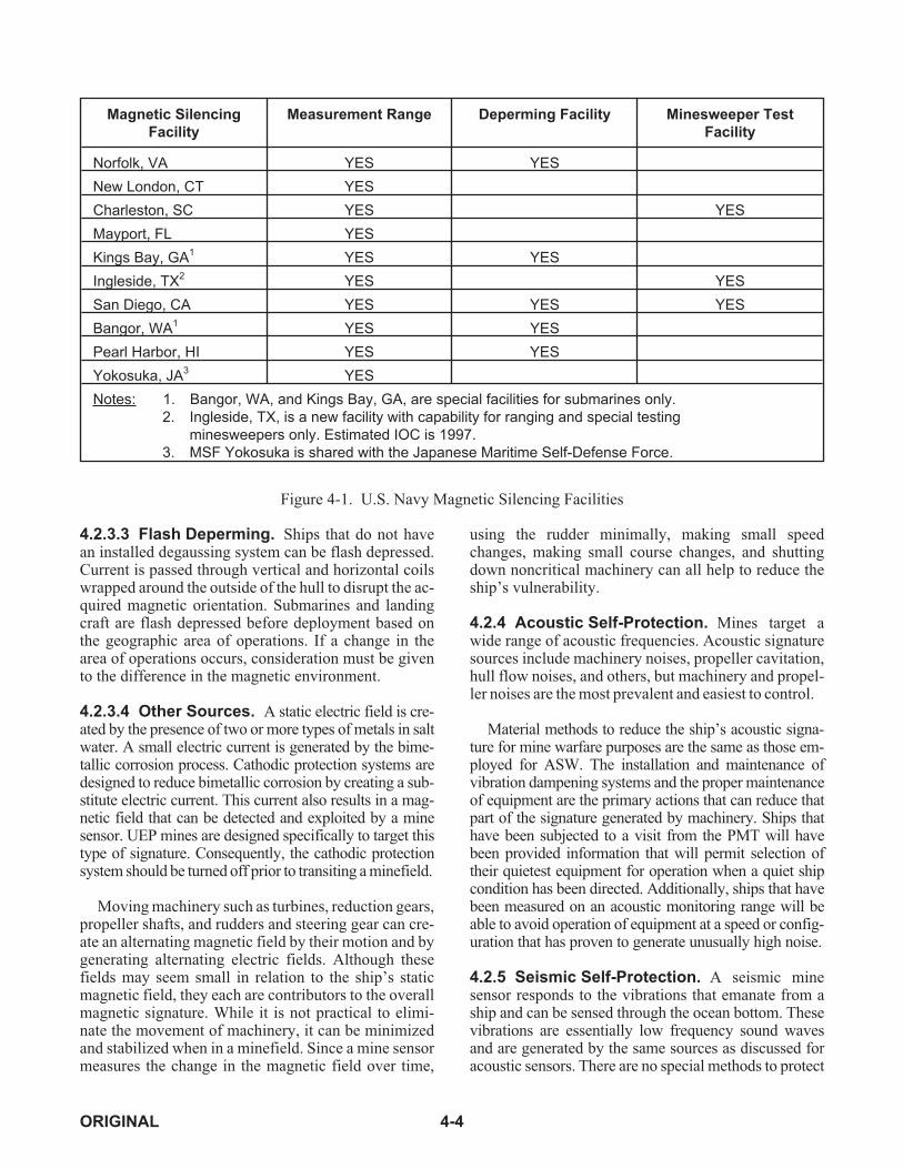
4.2.3.3 Flash Deperming. Ships that do not havean installed degaussing system can be flash depressed.Current is passed through vertical and horizontal coilswrapped around the outside of the hull to disrupt the ac-quired magnetic orientation. Submarines and landingcraft are flash depressed before deployment based onthe geographic area of operations. If a change in thearea of operations occurs, consideration must be givento the difference in the magnetic environment.
4.2.3.4 Other Sources. A static electric field is cre-ated by the presence of two or more types of metals in saltwater. A small electric current is generated by the bime-tallic corrosion process. Cathodic protection systems aredesigned to reduce bimetallic corrosion by creating a sub-stitute electric current. This current also results in a mag-netic field that can be detected and exploited by a minesensor. UEP mines are designed specifically to target thistype of signature. Consequently, the cathodic protectionsystem should be turned off prior to transiting a minefield.
Moving machinery such as turbines, reduction gears,propeller shafts, and rudders and steering gear can cre-ate an alternating magnetic field by their motion and bygenerating alternating electric fields. Although thesefields may seem small in relation to the ship’s staticmagnetic field, they each are contributors to the overallmagnetic signature. While it is not practical to elimi-nate the movement of machinery, it can be minimizedand stabilized when in a minefield. Since a mine sensormeasures the change in the magnetic field over time,
using the rudder minimally, making small speedchanges, making small course changes, and shuttingdown noncritical machinery can all help to reduce theship’s vulnerability.
4.2.4 Acoustic Self-Protection. Mines target awide range of acoustic frequencies. Acoustic signaturesources include machinery noises, propeller cavitation,hull flow noises, and others, but machinery and propel-ler noises are the most prevalent and easiest to control.
Material methods to reduce the ship’s acoustic signa-ture for mine warfare purposes are the same as those em-ployed for ASW. The installation and maintenance ofvibration dampening systems and the proper maintenanceof equipment are the primary actions that can reduce thatpart of the signature generated by machinery. Ships thathave been subjected to a visit from the PMT will havebeen provided information that will permit selection oftheir quietest equipment for operation when a quiet shipcondition has been directed. Additionally, ships that havebeen measured on an acoustic monitoring range will beable to avoid operation of equipment at a speed or config-uration that has proven to generate unusually high noise.
4.2.5 Seismic Self-Protection. A seismic minesensor responds to the vibrations that emanate from aship and can be sensed through the ocean bottom. Thesevibrations are essentially low frequency sound wavesand are generated by the same sources as discussed foracoustic sensors. There are no special methods to protect
ORIGINAL 4-4
Magnetic Silencing
Facility
Measurement Range Deperming Facility Minesweeper Test
Facility
Norfolk, VA YES YES
New London, CT YES
Charleston, SC YES YES
Mayport, FL YES
Kings Bay, GA1
YES YES
Ingleside, TX2
YES YES
San Diego, CA YES YES YES
Bangor, WA1
YES YES
Pearl Harbor, HI YES YES
Yokosuka, JA3
YES
Notes: 1. Bangor, WA, and Kings Bay, GA, are special facilities for submarines only.
2. Ingleside, TX, is a new facility with capability for ranging and special testing
minesweepers only. Estimated IOC is 1997.
3. MSF Yokosuka is shared with the Japanese Maritime Self-Defense Force.
Figure 4-1. U.S. Navy Magnetic Silencing Facilities
against seismic sensors other than those described foracoustic self-protection.
4.2.6 Pressure Self-Protection. There is little thatcan be done from a material standpoint to reduce theship’s signature against a mine sensor that uses pres-sure as one of the influences. The Bernoulli effect be-tween the moving hull and sea bottom determines thepressure signature, and the hull form cannot be modi-fied. In some cases, reducing the ship’s draft may bepossible by reducing ballast, and this should reduce thepressure signature. Except in unusual cases, however,the change will be very slight and possibly insignifi-cant. Reducing the ship’s speed to bare steeragewaycan reduce a ship’s pressure signature and is by far themost effective means available to reduce risks frompressure activated mines.
4.3 TACTICS
4.3.1 Ship’s Self-Protection. Tactics for individ-ual ships are separated into general, drifting/contact,moored, magnetic, acoustic, and pressure categories. If thetype of mine threat has been verified, some tactics may beignored, but in most cases all tactics that do not prevent per-formance of the ship’s mission should be put into effect.General precautions to be taken by ships when transiting anMDA or any area suspected of mining (whether or not des-ignated an MDA) include the following:
1. Set and maintain maximum watertight integrity.Condition Zebra, or a modification of Zebra formain deck and below, will minimize damageshould a mine be detonated.
2. Station a damage control party with full gear in atopside area. Once a mine detonation occurs, itmay be difficult for key damage control personnelto get to the repair locker and obtain equipment.
3. Have all personnel don protective gear, such asbattle helmets, life jackets, and flak jackets. Top-side personnel should wear kapok or other natu-rally buoyant life jackets.
4. Muster all unnecessary personnel topside in anarea not subject to falling debris.
5. When the tactical situation permits, consider re-ducing the readiness state of some or all weaponssystems and stowing ordnance in the configura-tion that will best withstand shock.
6. Proceed over the same ground as other traffic. In thecase of contact mines, if other traffic has passedsafely, the track has been proven safe; if other mine
types are present, at least the track has beenproven clear of contact mines, and there is no in-creased risk by following another vessel.
4.3.2 Drifting/Contact Mine Tactics. The only otheraction that can be certain to reduce the potential forstriking a contact mine is to find a ship with a largerdraft/beam and follow in its path. The following arerecommended precautions:
1. Post mine lookouts. See paragraph 4.2.2.1 for adiscussion of equipment for mine lookouts.
2. Watchstanders must be given special trainingto be effective. They should report any contact,and the OOD should take interest in every con-tact so that the watch understands the impor-tance of his mission.
3. Use any available aircraft (helicopters are mosteffective) to conduct a visual search for driftingor floating mines along the intended track of theship. A search should be conducted in the morn-ing, at midday, and in the afternoon along theintended track adjusted for set and drift. Seeparagraph 4.2.2.2 for a discussion of visualsearch techniques.
4. Increase surveillance following rough seas orstorms that may have caused mine mooring ca-bles to break, setting the mine adrift.
5. Plot drift patterns for the area. NAVOCEANOhas a prediction program for drift patterns thatcan be used to estimate the danger area of minesthat break loose or are set adrift. If prevailingcurrents and winds are not known for the area,special buoys that are tracked by satellite to re-veal the drift pattern can be dropped.
4.3.3 Moored Mine Tactics. Generic mine avoid-ance sonar procedures, where a mine avoidance sonarhas been installed and specific tactical procedures havebeen developed, should be followed. The following de-scription of procedures is intended to give the com-mander an appreciation for the tactics used with a mineavoidance sonar installed in any unit other than anMCM ship.
Mine avoidance sonars typically are effective formine detection at speeds of 8 knots or less. Above thisspeed, the sonar picture is degraded, and the detectionrange may be insufficient for safe avoidance. Detectionranges can vary greatly, but few will be greater than600 to 800 yards. Once a contact is detected, it must be
4-5 ORIGINAL
recognized as a possible mine, and the decision to ma-neuver must be made very rapidly.
The time for maneuvering to avoid a contact is deter-mined by the ship’s speed, the dangerous distance forthe particular mine, and the range at which the decisionis made. The dangerous distance is the minimum rangeat which a mine can be passed without endangering theship. For a contact mine, that might be 100 yards. Ifthere is reason to believe the mine may be an influencetype, the dangerous distance should be increased to atleast 300 yards.
To the maximum extent possible, prior to executingthe turn, the mine avoidance sonar should be used to in-vestigate the new heading. This is particularly importantif the turn is ordered to avoid a sonar contact. Mines areusually spaced just a few hundred yards apart, and if theship is approaching a mine line, the avoiding turn for onemine may lead to collision with another mine.
4.3.4 Magnetic Mine Tactics. Tactical measuresfor self-protection against magnetic mines are as follows:
1. Ensure each ship’s degaussing system is ener-gized and operating properly. Do not energize ordeenergize a degaussing system when a ship isin mined waters.
2. Secure the cathodic protection system severalhours prior to entering an area believed to have amagnetic mine threat.
3. Secure all unnecessary electrical equipment thathas a significant power draw.
4. Travel in the deepest water possible and transitshallow areas at high water. When possible, con-sider reducing water ballast to reduce draft. Themagnetic signature decreases with distance fromthe hull, so the greater separation that can bemaintained between ground mines and the ship,the better.
5. Slow the ship’s speed. Faster speeds generallymean higher signatures from moving machineryand a higher rate of change in magnetic signa-ture compared to the earth’s magnetic field.
6. Avoid dropping or raising the ship’s anchor be-cause these actions cause a change in the magneticsignature, not only from the electric motor drivenwinch, but also from the relocation of a large massof metal. The same is true for movement of largeweapons or aircraft and vehicle elevators.
7. Avoid starting and stopping electrical machin-ery that has high current because those actionsdraw a momentary spike in the ship’s magneticsignature. It may be better to start equipmentand leave it running if it must be used during aminefield transit.
4.3.5 Acoustic/Seismic Mine Tactics. Tacticalmeasures for self-protection against acoustic/seismicmines are as follows:
1. Implement the Quiet Ship Bill, which should resultin minimizing running equipment and selecting thequietest equipment options. Avoid noisy operations,such as operation of grinding or chipping tools or un-necessary use of weapons handling systems.
2. Operate Prairie/Masker systems, when installedand, if appropriate, at the ship’s intended speedto mask machinery and propeller noises.
3. Transit the deepest channel possible. As with themagnetic signature, the acoustic signature de-creases with distance between the ship and themine.
4. Transit during high water to increase the avail-able depth.
5. Transit at the slowest speed consistent with thetactical situation to reduce machinery, hull, andpropeller noises.
6. Minimize speed and rudder changes to reduce ma-chinery noise and flow noise generated by propul-sion system changes and rudder movement.
4.3.6 Pressure Mine Tactics. Tactical measuresto reduce the pressure signature are relatively limited.They are as follows:
4.3.6.1 Maximize Water Depth. Remaining in thedeepest channel and transiting at high water will reducethe pressure signature sensed by a ground mine.
4.3.6.2 Minimize Speed. Maintaining the mini-mum speed permissible in the tactical situation, whilestill maintaining steerageway, will reduce the relativewater flow between hull and bottom and reduce thepressure signature generated. If the ship could driftthrough the minefield on natural current, there wouldbe no pressure signature generated.
4.3.6.3 Use Masking Techniques. A high sea state,which increases the ambient pressure against which themine is trying to detect the ship, will tend to mask the
ORIGINAL 4-6
ship’s passage. (Unfortunately, the tactical situationdoes not usually allow a delay until favorable weatherconditions exist.)
4.3.6.4 Defeat the Firing Sensor. Pressure sen-sors are not generally used independently, and the sec-ondary sensor may be more easily defeated.
4.3.7 Group Self-Protection Tactics. Tacticsfor single ships also apply to groups of ships. Con-ducting a helicopter search ahead of a dispersed battlegroup requires a lot of helicopter time to cover the largearea. Therefore, if transiting in mined waters, a columnformation is the best for mine avoidance, althoughother warfare considerations may not be satisfied.
If Kingfisher-equipped ships are available, theyshould be placed in the front of the formation, and otherships should attempt to follow in their path.
A Q-route system is a pattern of preplanned, dor-mant shipping lanes to be activated by the area com-mander in time of war. The routes are designed tomaximize the effectiveness of MCM by limiting theamount of area MCM forces must cover and by allow-ing the ship to traverse the most favorable bottom envi-ronment that is practical for the area. A Q-route systemincludes coastal routes, which follow the coastline fortransit from port to port; approach routes, which con-nect coastal routes to the port entrance; breakout routes,which connect the coastal route to open water (beyondmine threat); and link routes, which provide connec-tions between coastal routes where useful.
Q-routes are listed in the AHP-7 series of publica-tions, including a U.S. Supplement for routes of U.S.Navy interest only. (A volume listing Atlantic and GulfCoast routes has not been published yet. These routesare listed in an unofficial COMINEWARCOM supple-ment to AHP 7.)
Navigational warning messages, sent via the “Q”message system, distribute classified information onknown or suspected minefields and channel status (upto the NATO Secret level). The messages are originatedby an area commander, such as COMUSMARDEZ-LANT or COMUSMARDEZPAC, if activated. TheQ-message information is also sanitized and providedto merchant ships or civilian convoy commanders.
Convoying of ships allows for the concentration ofdefensive assets (i.e., MIW, AAW, ASW, and SUW) toprotect merchant shipping. This results in reduced effi-ciency for high speed merchant traffic that must waitfor the convoy departure and travel at the speed of the slow-
est convoy member. However, on the positive side, itpermits mutual support, allows the best navigation sys-tem to lead, and if escorts have mine detection andavoidance capabilities, results in a significant reductionin threat.
4.3.8 Preplanned Responses. Preplanned re-sponses to certain situations should be promulgatedprior to encountering mines. The MIWC provides stan-dardized procedures in the OPTASK MIW orOPTASK MIW Supplement. These should includequick reporting procedures, standard maneuvering in-structions for different types of mine threats, and minecontact identification and disposal policy.
A preplanned response should include steps to avoidany contact that has been detected while still holdingcontact and procedures for marking contacts with smokeor dye markers dropped near but not on the contact.
4.3.9 Mine Disposal. Mines may be discovered bynon-MCM units when no MCM force is available. Spe-cific procedures to be followed are found in the NavyWide Standing OPTASK MIW. If the mine is a teth-ered or bottom mine, an MDA will be designated andan EODMCM detachment dispatched to conduct dis-posal. If the mine is drifting, an MDA may be desig-nated because of the potential for other mines, butimmediate action is necessary. Drifting mines are diffi-cult to track in darkness, so disposal before darkness isdesirable. After receiving a mine report, the MIWC willdetermine whether an EODMCM team can be trans-ported to the scene. EOD mobile detachments deployedwithin the CVBG and ARG have limited MCM capa-bility and are available within the battle group for im-mediate response. EOD swimmers can be delivereddirectly to the mine by helicopter if they are available.If no EOD swimmers are available, the MIWC may di-rect the ship to dispose of the mine by gunfire. Disposalby gunfire is the method of last resort. On the average,one in seven mines hit by gunfire detonates, resulting ina shrapnel hazard to ships and helicopters. Before fir-ing, the ship should be prepared for blast, with topsidepersonnel wearing flak jackets and helmets; shotsshould be fired from the maximum practical range. A50-caliber machine gun has sufficient range and powerto dispose of a mine, although, again, this is a last resortoption. Firing at a mine from a helicopter is not recom-mended. The 700-foot radial range and arc of shrapnelfrom a mine exploding on the surface places any heli-copter nearby in danger. Mines that do not detonate re-main functional and, if they sink to the bottom, maydetonate if disturbed by fishing nets or anchors. Minesmay also flood partially and float somewhere in the wa-ter column as a serious threat to ships.
4-7 ORIGINAL
Any ship that is equipped with a helicopter or smallboat may at some time be tasked to provide transporta-tion for EODMCM detachments and other EOD teams.Helicopters are not threatened by mines as long as theyremain clear of explosive disposal procedures and donot attempt to dispose of mines by gunfire. Small boats,however, can be threatened not only by contact mines,but they also may provide sufficient magnetic or acous-tic signature to actuate influence mines. EODMCM de-tachments normally use a rubber boat with lowmagnetic and acoustic signature. If other surface craftare being used, they should restrict engine operations tomedium or low speed to reduce acoustic signature andstay well clear of the mine contact.
4.4 PASSIVE MINE COUNTERMEASURESFOR SUBMARINES
Submarines have many of the same concerns for re-ducing the threat from mines as do surface ships. A ma-jor difference, however, is that many of the actionsneeded to reduce acoustic/seismic and magnetic signa-
tures for a submarine are the same actions they carryout to maintain the maximum effectiveness of their pri-mary sensor and reduce all other threats to their exis-tence. High quality maintenance to reduce noise andEMI sources on the submarine also reduces the mag-netic and acoustic source level for mines.
U.S. submarines do not have a degaussing system.They have their signature read periodically and areflash depressed when required. If a change in the areaof operations occurs, consideration must be given to thedifference in the magnetic environment, and extra pre-cautions must be taken if the submarine cannot revisitthe deperming facility.
More specific information and tactics about subma-rine MCM exceed the classification of this publication.Sources of additional information include NWP 3-15.53and COMSUBDEVRON TACMEMO FZ-6060-1-90.
ORIGINAL 4-8
APPENDIX A
MIW TERMS
A.1 INTRODUCTION
MIW has its own language using many terms that,although some may appear in other warfare areas, carrydifferent or more specific definitions when applied toMIW. Additionally, there are terms used by allied MIWforces that seem similar to U.S. terms, but have mean-ings that differ to some extent. Allied or coalition forceoperations can be far more difficult when the forces andcommanders are not able to communicate freely be-cause of the misunderstandings caused by different ter-minology or the different connotations of terms.
This appendix provides a compendium of terminol-ogy found in the primary Allied MIW reference, ATP6, and the NWP 3-15 series (formerly the NWP 27 se-ries) publications, as well as some new terminologythat has come into common use within MIW. In para-graphs A.1.2 and A.1.3 and their subparagraphs, keydefinitions of mining and MCM are given with somediscussion. Paragraph A.2 provides an alphabetical list-ing of Allied terms from ATP 6, shown in normal styletype, and U.S.-unique terms/definitions, shown in ital-ics. In some cases, italicized type is used to provide fur-ther interpretation of an Allied term as it applies to U.S.MIW forces or systems. These are terms that are notlisted in Joint Pub 1-02 or whose meanings differ fromthe version listed in that publication.
A.1.1 Mining. Mining is one of the two distinctsubdivisions of MIW. Mining operations are used tosupport the broad task of establishing and maintain-ing control of essential sea areas and embrace allmethods whereby naval mines are used to inflictdamage on enemy shipping and/or hinder, disrupt,and deny enemy sea operations. Mines may be em-ployed either offensively or defensively to restrictthe movement of surface ships, submarines, and un-derwater systems and personnel. Mines can be usedalone to deny free access to and from ports, harbors,and rivers, as well as movement through SLOC.Mines can be used as a force multiplier to augmentother military assets to reduce the enemy surfaceand submarine threat. A mining campaign is intendedto inflict damage on enemy ships that challenge
the minefield, thereby having an adverse affect ontheir defense, offensive operations, and logisticalsupport efforts, but it can also force the enemy intoconducting a heavy mine countermeasures effort thatmay exceed the magnitude of the mining operationitself. Enemy ships kept at their base or deterred intransit by mining may be rendered as ineffective forthe immediate war efforts as if they were otherwisesunk or destroyed. Further, delays in shipping may beas costly to the enemy as actual losses. The threatposed by a minefield may be real or it may only beperceived, but mining does have a significant psy-chological impact on the enemy by forcing him tocombat an unseen force.
A.1.1.1 Defensive Mining. Defensive mining op-erations are those conducted in undisputed interna-tional waters or straits with the declared intention ofcontrolling shipping in defense of sea communications.Defensive mining is designed to provide protection bydenying enemy access to the friendly force’s SLOCs,harbors, beaches, chokepoints, and surface and subma-rine operating areas. A key element to a defensivemining campaign is that safe passage must be providedfor the merchant and combat shipping of friendlyforces, as well as those of neutral nations. Either a safe,mine-free lane must be left in the minefield, or anotherroute must be available that will take the traffic aroundthe minefield. These safe areas would require monitor-ing from other forces to ensure that they are not alsoused by the enemy, unless the intent of the mining oper-ation is to force the enemy through a secondary route.
A.1.1.2 Offensive Mining. Offensive mining op-erations are those conducted in enemy territorial watersor waters under the control of the enemy. The intent ofan offensive mining campaign is to deny, delay, or dis-rupt enemy ship movements. This is accomplished bydestroying or obtaining mission abort damage on thenaval and merchant ships that challenge the minefieldand/or by requiring the enemy to conduct a large MCMeffort to reduce the mine threat.
A.1.1.3 Protective Mining. Protective mining isconducted in a nation’s own territorial waters or waters
A-1 ORIGINAL
under the control of an allied nation to protect ports,harbors, anchorages, coasts, and/or coastal routes fromenemy maritime traffic. Safe passage for friendly andallied combat forces must be provided through themined areas. If merchant shipping will be transitingthrough the mined area, it also must be provided withsafe passage. Since protective mining operations areconducted in restricted waters that the nation’s orfriendly maritime forces will be transiting, it is ex-tremely important that the mines be accurately placedso that they do not pose a threat to traffic transitingthrough the safe channel.
A.1.2 Mine Countermeasures. MCM is the otherdistinct subdivision of MIW, and it includes all offen-sive and defensive measures for countering a minethreat, including the prevention of enemy minelaying.MCM includes any actions taken to counter the effec-tiveness of and/or reduce the probability of damage tosurface ships and craft or submarines from underwatermines. Further discussion of offensive and defensivecountermeasures terms and definitions can be found inChapter 3.
A.1.2.1 Offensive MCM. Offensive MCM includesall actions taken to prevent the enemy from success-fully laying mines. Offensive MCM includes any ac-tion resulting in the destruction of enemy minelayersand mine stockpiles, as well as the laying of defensiveminefields in friendly waters to prevent mine deliveryby enemy surface or subsurface vessels.
A.1.2.2 Defensive MCM. Defensive MCM includethose operations intended to reduce the effect of enemyminelaying once the mines have been placed in the wa-ter. In broad terms, defensive MCM is divided into twoclasses of action or concepts: passive MCM and activeMCM.
A.1.2.3 Passive MCM. Passive MCM include allmeasures employed to reduce the susceptibility of shipsand submarines to mine actuation and explosion. Thiswould include but not be limited to minefield location
and avoidance, as well as the reduction of the ship’smagnetic signature (e.g., degaussing, deperming),acoustic signature (e.g., quiet ship bill), and pressuresignature (e.g., slow transit through deep water).
A.1.2.4 Active MCM. Active MCM include the useof ships, aircraft, systems, and personnel to locate andneutralize mines. Active MCM can be divided into twocategories: mine hunting and mine sweeping.
A.1.2.5 Mine Hunting. Mine hunting involves thelocation of individual mines so that actions may betaken to avoid, remove, or destroy them. It is aone-on-one operation, as opposed to minesweeping,which seeks to clear an area of mines. Mine hunting in-cludes mine detection, classification, localization,identification, and neutralization.
A.1.2.6 Mine Sweeping. Minesweeping is theMCM technique of sweeping a region of water eitherby traversing it with mechanical or explosive sweepgear designed to sever the moorings of moored minesor by producing the influence fields necessary to actu-ate the firing mechanisms of influence mines using asweeping system or guinea pig ship. Minesweeping op-erations affect all mines located in the area that iscovered by the sweep being employed, instead of com-bating just one mine at a time.
A.1.2.7 Brute Force Mine Clearance. This is amine clearance technique that may take place inde-pendent of minehunting or minesweeping operations.Brute force involves the use of high explosives in sucha manner to cause sympathetic detonation, neutraliza-tion, or physical displacement of a significant numberof the mines in an area. It is most frequently consideredin relation to amphibious operations where very shal-low water and surf zone clearance is desired in a rapidmanner and where a relatively narrow path through aminefield can permit landing craft to transit to thebeach and establish a foothold.
ORIGINAL A-2
A.2 ALPHABETICAL TERMINOLOGCOMPARISON
A
Acoustic Signature. The characteristic pattern ofthe target’s acoustic influence as detected by the mine.
Active Acoustic Mine. A mine actuated by the re-flection from a target of a signal emitted by the mine.
Actuation. The response of a mine-firing mechanismto an influence (or series of influences) in such a waythat all requirements of the mechanism for firing orfor registering a ship count are met.
Actuation Level. The minimum influence signal levelneeded to actuate a mine. The level of intensity and theduration of time that the influence field must be appliedto satisfy the firing circuit requirements of the mine.
Actuation Mine. A mine used for training MCMforces in mine sweeping. It has an inert loaded minecase, operable components, and a flare and smokesignal to indicate actuation. The mine may be deliv-ered by either air or surface craft.
Actuation Mine Simulator (AMS). A device usedfor MCM training and fleet exercises to simulate in-service mines. It contains the service mine intelligencesupplemented with components to control timing, de-tection functions, six flare and smoke signals, and anactuation recorder to indicate actuations.
Actuation Probability. The average probability ofa mine of given type being actuated by one run of thesweep within the actuation width.
Actuation Probability Area. A horizontal planewithin which the sweeper-sweep combination willintercept an armed mine or its appendages, causing abuoyant mine’s mooring to be cut, a contact mine tobe fired, or an influence mine to be actuated.
Actuation Width (W). The total area under an actu-ation curve. The path width over which mines can beactuated. Also called “average firing width.”
Aggregate Actuation Width. This is numericallyequal to the area under the graph showing how mineactuation probability varies with distance from thesweep’s center of influence.
Aggregate Danger Width. For a given mine, this isthe integral of Pd(y), where y is the athwartship dis-
tance from the track of the MCMV and Pd is the prob-ability of an actuation within the MCMV’s dangerarea.
Aggregate Detection Width. This is numericallyequal to the area under the graph of mine detectionprobability for detectable mines against distancefrom the track of the detection gear.
Airborne Mine Countermeasures (AMCM). MCMoperations conducted from an aircraft platform. In-cludes spotting, watching, hunting, sweeping, anddestroying.
Amphibious Breach. A type of deliberate breachspecifically designed to overcome antilanding defensesto conduct an amphibious assault. It is characterized bythorough reconnaissance, detailed planning, extensivepreparation and rehearsal, and a buildup of combatpower. One or more subordinate units are specificallytasked to perform the role of support, breach, and as-sault forces. The amphibious breach is centrallyplanned and executed. Units conduct an amphibiousbreach when there are no other suitable landing areas.
AN/ALQ-141. An acoustic sweep device electricallypowered from the helicopter via a tow cable.
Analytic Countered Minefield Planning Model(ACMPM). A model developed for planning countered
minefields. It uses a scenario in which an enemychooses a channel in a minefield and then employscountermeasures to remove the mine threat.
AN/AQS-14. An AMCM side-scanning, minehuntingsonar towed by the MH-53E helicopter.
AN/PQS-2A. An active/passive, hand-held sonarused by divers to locate submerged objects or to de-tect active acoustic pingers.
AN/SLQ-37. The magnetic/acoustic minesweepingsystem aboard the MCM-1 Class ships.
AN/SLQ-38. The mechanical minesweeping systemaboard the MCM-1 Class ships.
AN/SLQ-48. A mine neutralization system (MNS) uti-lizing a remotely operated vehicle (ROV) carryingcable cutters and a bomblet.
AN/SLQ-53. The single ship deep sweep (SSDS) me-chanical minesweeping system developed for theMHC-51 Class ships that utilizes converted light-weight mechanical AMCM sweep gear.
A-3 ORIGINAL
AN/SPU-1W. Magnetic orange pipe (MOP) AMCMmagnetic minesweeping gear.
AN/SQQ-30. A variable depth SMCM minehuntingsonar aboard some of the MCM-1 Class ships.
AN/SQQ-32. A variable depth SMCM minehuntingsonar aboard some of the MCM-1 Class and theMHC-51 Class ships.
AN/SSN-2. The precise integrated navigation system(PINS) aboard MCM-1 Class ships.
AN/SYQ-13. The navigation/command and controlsystem used on MHC-51 Class ships.
Antenna Sweep. A shallow wire sweep configura-tion that actuates the mine by contact with theantenna.
Anti-Invasion Mine. A mine capable of use in veryshallow water against landing craft, fast patrolboats, surface effect vehicles, and other amphibiousassault vehicles.
Anti-MCMV Mine. A mine that is laid or whosemechanism is designed or adjusted with the specificobject of damaging MCM vehicles.
Anti-SMCM Mine. A mine that targets MCM ships.Includes shallow water moored mines, snaglinemines, highly sensitive magnetic mines designed forwell-degaussed ships, and medium actuation levelacoustic mines. Also called an antisweeper mine.
Antisubmarine Minefield. A field laid specificallyagainst submarines. It may be unsafe for all vehicles,or it may be deep and safe for surface vessels to cross.
Antisweep Device. Any device incorporated in themooring of a mine or obstructor or in the mine’s cir-cuits to make the sweeping of the mine moredifficult.
Antiwatching Device. A device fitted in a mooredmine that causes it to sink should it watch (i.e., showon the surface), so as to prevent the position of themine or minefield being disclosed.
AN/WQN-1. The special acoustic sweep used onMCM-1 Class ships.
Approach Route. A sea route that joins a port to thecoastal or a transit route.
Arming Device. A safety mechanism that interruptsthe primary explosive firing train until a unique com-bination of environments is satisfied.
Assembly Configuration of Mines. This is a meansof referring to the assembly configuration of minesby various numbered configurations.
Asymmetrical MCM Gear. Any MCM gear whosecenter of actuation, influence, detection, or cutting isdisplaced from the centerline of the MCM platform.
Attrition MCM Operations. The continuous ap-plication of MCM to keep the risk from m i n e s t oall vehicles as low as possible. These operationsare appropriate against minefields that are beingreplenished.
Attrition Objective. The objective of attrition is tokeep the threat of mines to ship traffic as low as possi-ble when traffic must continue to transit the minedwaters for a comparatively long period of time andwhen the mines cannot be cleared in a short time be-cause of factors such as replenishment or the use ofmine mechanisms with delayed arming or high shipcount settings.
Audio Frequency (AF). See also “Acoustic Cir-cuit.” Frequencies between 30 and 1500 Hz.
Avenger Class. MCM-1 Class Mine Countermea-sures ships.
Average Actuation Area. The integral, over aplane perpendicular of the centerline of the targetship, of the probability, P(y,z), of actuation of a mineunder specified conditions.
Average Actuation Width. The integral, overathwartship distance between the mine and thekeel of the target ship, of the probability, P(y), ofactuation of a mine at a given depth and underspecified conditions.
Avoidance. Actions taken to change a ship’s coursefor the purpose of avoiding a mine. The deliberate actof maneuvering around a mine or minefield once ithas been localized.
B
Bogie. A device mounted on the minelayer’s rails atthe foremost end of a mine train, around which passesthe hauling aft wire that will push the train aft whenthe wire is hove in.
ORIGINAL A-4
Bomblet. Explosive charge for mine neutralization.
Bottom Sweep. A sweep, either wire or chain, usedeither to sweep moored mines close to the bottom orto remove mines from a channel by dragging them toa nominated area. The sweep configuration may beone or two ships dragging a wire or chain over thebottom.
Breakthrough. A time-critical operation applied tothe mine countermeasures tactic of channelizingthrough a minefield to gain passage for ships.
Buried Mine. A mine that is partially or fully coveredby bottom sediment.
C
CAPTOR. Acronym for “EnCAPsulated TORpedo.”This weapon has the official designation of Mine Mk60. This is a passive/active acoustic deep water ASWmine that launches an Mk 46 torpedo at the targetwhen the detection and validation criteria have beensatisfied.
Case Depth. For moored mines, this is the waterdepth at which the explosive charge is held by themooring line. For ground mines, the case depth is thesame as the water depth.
Casualty Distribution. The set of probabilities forevery possible number of casualties from zero to n outof n transit attempts (e.g., 40 percent probability of 3casualties in 10 transits).
Casualty Rate. The expected number of casualtiesper time period in a sustained attrition miningcampaign.
Channel Conditioning. An operation that removesminelike objects from channels, harbor approaches,and Q-routes to reduce the number of minelike andnonminelike bottom objects detectable by minehunt-ing systems.
Channelization. The tactic of sending all transitorsthrough the same strip of a minefield.
Check MCM Operation. An MCM operation tocheck that as far as possible no mines are left after aprevious MCM operation.
Classification Range. The range at which a contactis classified. (This may be amplified by the prefixes“actual expected” or “maximum.”)
Clearance Diver. Diver who is trained for air scubaand mixed gas scuba diving and qualified to carry outtasks in mine/ordnance search, investigation, recov-ery, and removal, both underwater and ashore.
Clearance Diving Team. Group of clearance diversestablished to conduct clearance diving tasks. It maybe embarked in an MCM vessel or operate from anashore mobile support facility. The group includes aleader and medical personnel. (Allied equivalent toEOD plus salvage divers.)
Clearance MCM Operations. Operations whoseobjective is to clear all mines from an area, channel,or route.
Clearance Rate. The area that would be cleared perunit of time, with a stated minimum percentage clear-ance, using specific MCM procedures.
Clearance Operations. The process of sweeping orhunting in a mined area with the aim of clearing all ora high percentage of mines from an area, channel, orroute. A specific percentage of clearance is usuallyspecified.
Clearing. The level of MCM effort required to sweep,hunt, or otherwise neutralize a high percentage of themines in a field, whether of a certain type or totalpossible/known types.
Clearing Objective. The objective of clearing is toremove most mines from the assigned area. Since it isgenerally impossible to guarantee that all mines arecleared, a goal is assigned, such as removing or neu-tralizing 99.5 percent of the mines.
Closed-Loop Sweep. A magnetic sweep in whichthe sweep current is carried entirely by insulatedelectrical conductors and does not depend upon sea-water to complete the electric circuit. The conductorsare diverted to one or both sides using components ofthe oropesa mechanical sweep.
Clutter Density. The number of NOMBOs persquare inch in an operational segment.
Coastal Route. A sea route, normally following thecoastline, that joins adjacent approach routes.
Coincidence Method. The method whereby an ex-plosive charge or a marker is guided until its positioncoincides with that of the mine as shown on the sonardisplay.
A-5 ORIGINAL
Contact Level. The minimum suction that will firstoperate the pressure unit contact.
Continuous Traffic. Aflow of targets and/or sweepersatasteadyaveragerateover the timeperiodof interest.
Controlled Mine. A mine that, after laying, can becontrolled by the user to make the mine armed or safeor to fire the mine.
Countered Field. A minefield in which some level ofmine countermeasures is undertaken by the enemy.For planning purposes, the various levels of ex-pected MCM are defined as follows:
a. NONE. Airspace not controlled by enemy,no mine hunting, no mine watching, no guinea pig ac-tivity, no minehunting/sweeping assets nearby, primi-tive countermeasures only.
b. LOW. Minesweepers/hunters available ornearby, low guinea pig activity and mine watching.
c. MEDIUM. Minesweeping/hunting available,airspace controlled by enemy, moderate guinea pig ac-tivity, high value units targeted.
d. HEAVY. Minesweeping/hunting assets de-ployed in the area, line and depth charges available, air-space controlled by enemy, heavy guinea pig activity.
Counter-Countermeasures Setting (CCM). Optionson the weapons available to the minefield planner tolessen the effectiveness of anticipated enemy minecountermeasures efforts.
Craft of Opportunity (COOP). Nonmilitary craftthat, in an emergency, can be shifted from normal useto military use with little or no cost and effort.
D
Damage Distance (Yd). Theathwartshiprangewithinwhich a mine must detonate to cause a specified level ofdamage to the target.
Damage Level. Measure of desired danger. Fourstandard categories are Kill, Imminent Loss Likely,Mission Abort, and Onboard Repairs Possible.
Damage Width (Wd). The integral of the probability,P(y), of actuation of a mine under specified conditions,integrated only over those values of athwartship dis-tance y for which the explosion of the mine is likelyto do at least a specified amount of damage.
This is the area under an actuation probability curvewithin the damage distances on each side of the ship.
Dangerous Front. The athwartship distance in whichthere is a likelihood that an MCM platform could bedamaged by a mine that the MCM platform has swept.
Deep Moored Mines. Moored mines with strong,small gauge cables that permit employment at greatdepth.
Delay Arm. A feature on a mine causing it to remainunarmed for a selected period of time after laying.
Delay Rise. A feature on a moored mine causing thecase to remain attached to the anchor for a selectedperiod of time after laying.
Delay Time. The time between the application of theminimum pulse field and the registration of the lookunder consideration.
Delayed Rising Mechanism. A device used withmoored mines that enables the release and rising ofthe mine to be deployed.
Deperming. The use of high currents in coils tempo-rarily arranged around a ship to reduce its magneticsignature.
Depressor. A hydrodynamic planing device used toobtain depth in a mechanical sweep.
Destruction Radius. The maximum distance froman exploding charge of stated size and type at which amine will be destroyed by sympathetic detonation ofthe main charge, with a stated probability of destruc-tion, regardless of orientation.
Destructor Mine (DST). A mine developed for usein Vietnam against junks and sampans. It uses amodification kit to convert an Mk 80 series general-purpose, low-drag bomb into a mine that can beused either on land or in the water.
Detecting Mechanism. A mine subassembly, includ-ing sensors, relays, timing, and delay mechanisms, thatdetects the presence of a targetlike influence and thatprovides the necessary initiation signal to the mine-firing mechanism to actuate the mine.
Detection Probability (Pd). The ratio of the num-ber of mines detected on a single run to the number ofdetectable mines within the characteristic detectionwidth.
ORIGINAL A-6
Detection Width. The width of path over whichmines can be detected on a single run at a given Pd.
DG Code Number. The peak vertical component ofthe magnetic field in microtesla under a ship on theworst heading and at a certain depth.
Directive. Ordered as A, B, or C. The directive or-dered indicates the risk of MCM vessels acceptablewhile carrying out an MCM operation.
Dispose. Elimination of mines by either countermining,mine neutralization, or removal.
E
Electrical depth. In some cases, the electrical depthis greater than the actual depth. This occurs when theupper layer of the sea bed becomes saturated withseawater such that the conductivity of this layer ap-proximates the conductivity of the seawater.
Electrodes. Components of a magnetic sweep. Thecables from which electric current is passed from oneto the other via seawater return.
Enabling MCM. Enabling countermeasures are de-signed to counter mines once they have been laid.Some enabling MCM operations are undertaken fol-lowing the termination of conflict solely to eliminateor reduce the threat to shipping posed by residual seamines. However, most enabling MCM operations areundertaken during conflict to permit (enable) othermaritime operations, such as power projection, to beconducted. Enabling MCM includes passive and ac-tive MCM.
EODMCM Detachment. Personnel with specialtraining and equipment to relocate, neutralize, coun-termine, or render safe and exploit sea mines.
Exercise and Training Mine. A mine suitable foruse in MIW exercises that is fitted with visible or au-dible indicating devices to show where and when itwould normally fire. Adevice to assist in mine recov-ery may also be fitted.
Expected Casualties. The average number of ca-sualties in n transits of a minefield.
Exploratory MCM Operations. An MCM opera-tion in which a sample of the route or area is sub-jected to MCM procedures to determine the presenceor absence of mines.
Exploratory/Reconnaissance Objective. The ob-jective of exploratory/reconnaissance is to determinewheteher mines are present and, if present, the limits ofthe mined area. This is usually the first objective whenan enemy-laid minefield is suspected.
F
Fleet Service Mine Test Program (FSMTP). Aprogram with the primary purpose of determiningthe operational reliability of stockpile service mines.
Fraction of Area Covered. Used in MCM opera-tion to denote progress of the task; it is that fraction ofthe assigned task area that has to date been coveredby the tasked MCMVs.
G
Gas Bubble. Gas produced by an explosion expandsrapidly, producing a bubble of extremely high pres-sure. When the pressure falls below the pressure inthe surrounding water, the bubble collapses. Thebubble and the shock wave it propagates are the dam-age effects of an underwater explosion.
Geophone. A sensor used in seismic mines.
Guillotines. A portable, explosive, cable-cutting de-vice used to sever the tow wire in an emergency (heli-copter installed).
Guinea Pig. A ship used to determine whether anarea can be considered safe from influence mines un-der certain conditions or, specifically, to actuate pres-sure mines.
H
Harassment Mines. Those mines specifically set totarget sweepers or to enhance the psychologicalthreat of a minefield.
Hold-On Time. The time during which the thresholdrequirements of the mine must be satisfied.
Holiday. A gap in MCM coverage left unintentionallyduring MCM operations due to errors in navigation,station-keeping, buoy-laying, breakdowns or othercauses.
Homing Mine. A mine fitted with propulsion equip-ment that homes onto a target. The mine normallyrests on the sea bed or is secured to an anchor and isset in motion by a ship’s influence.
A-7 ORIGINAL
Horizontal Component. That component of the to-tal magnetic field in the horizontal plane.
Hunting. The act of searching for mines. This term alsocovers the marking and/or neutralization of mines.
I
Identification. The determination of the exact natureof an underwater object that has been detected andclassified.
Initial Threat. The probability that the first ship to at-tempt to transit a minefield will be damaged to atleast a specified level.
Intensity Mine Circuit. A circuit whose actuation isdependent on the field strength’s reaching a level dif-fering, by some preset minimum, from that experi-enced by the mine when no ships are in the vicinity.
Intercount Dormant Period (ICDP). The periodafter the actuation of a ship counter before it is readyto receive another actuation. This is an interval dur-ing which mechanism functions are reset and anothership count cannot be registered. It is used as a counter-countermeasures feature to prevent the runoff of mul-tiple ship counts on a single sweeper pass.
Interlook Dormant Period (ILDP). The time in-terval after each look in a multilook mine during whichthe firing mechanism will not register. During this pe-riod of time, the firing device either will not recognizecertain events or will respond in a unique manner.
Intermediate Water Depth Mine (IWDM). A weaponsystem targeted against both high- and low-speedsurface and subsurface targets in the gaps betweenshallow-bottom and deep-moored mines.
J
Jettisoned Mines. A mine that is laid as quickly aspossible to empty the minelayer of its mines withoutregard to their condition or their position relative toeach other. Jettisoned mines are normally released ina safe mode (without pulling arming wires). The wiremay, however, withdraw at water entry, arming themine. A mine that is discarded from the delivery vehi-cle and normal operation is not intended.
K
Kite. A device that, when towed, submerges and planesat a predetermined depth without sideways displace-
ment. This is a towed planing device that causes theinboard end of the sweep to assume a determineddepth. Also known as a depressor in mechanicalsweeping.
L
Leadthrough Operations. Leadthrough opera-tions are intended to assist traffic in the transit ofparts of a mined area that have previously been sub-ject to an MCM effort.
Leadthrough Vessel (LTV). A vessel that providesnavigational accuracy so that accompanying shipscan transit the area of least threat. No MCM tech-niques are employed. The LTV is equipped with pre-cise navigation equipment and has knowledge of thethreat present.
Link Route. A sea route, other than an approach,coastal, or transit route, that links any two or moreroutes.
Live Mine. A mine with an explosive filling and ameans of firing the explosive charge.
Live Period. In multilook mines, the maximum timeinterval after the first look during which additionallooks will be accepted to satisfy all of the subsequentlooks and mine logic to cause an actuation.
Locate. To establish the precise position of an under-water object relative to a ship or to a specific naviga-tional reference position.
Loop Sweep. A magnetic cable sweep in which thecurrent-carrying conductors are insulated from thewater throughout. In a single-ship sweep, the work-ing portion of the sweep is spread by diverters to forma loop in the water. Also called a closed-loop sweep.
M
Magnetic Orange Pipe (MOP) (AN/SPU-1W). AMCMmagnetic minesweeping gear. Primarily used forvery shallow water AMCM operations.
Magnetic Self-Protection. The protection of shipsand submarines by degaussing to reduce the mag-netic signatures and to minimize the possibility of de-tection by magnetic mines.
Magnetic Signature. The characteristic pattern ofthe target’s magnetic influence as detected by themine.
ORIGINAL A-8
Magnetic Silencing. The reduction of the magneticsignature of a ship through construction materialsand techniques, degaussing, and the control of mag-netic items aboard ship.
Marine Mammal System. An Explosive OrdnanceDisposal Detachment that employs marine mammalsto conduct mine countermeasures operations.
Marker Float. A mechanical sweep support device;visual reference of sweep performance.
Master Reference Buoy (MRB). F Mk 6 Mod 0minefield marker designed to have a small watch cir-cle and good position-keeping ability. It can be con-figured as a single- or three-point moor.
Maximum Output Conditions. Sweeping carriedout under maximum output conditions when sweepsare used at the full output of the generating source.
Maximum Towing Speed. The speed through thewater that may not be exceeded without causingdamage to the MCM gear or the towing vehicle.
MCM 1. USS AVENGER Class mine countermeasuresship.
MCM Command and Support Ship (MCS). A shipequipped to provide the command functions, supportservices, and repair resources to an MCM force.
MCM Commander. The officer who exercises tacti-cal control of all assigned MCM units.
MCM Commander’s Tactical Decision Aid(MCM CTDA). A set of computer programs that pro-
vides the capability to analyze, evaluate, and recon-struct MCM operations.
MCM Efficiency Parameter (Y). A measure of theeffectiveness of a sweep/search technique. Used toaccount for efficiencies in the navigation and controlof MCM systems.
MCM Level (M). The average number of times that arepresentative mine is exposed to an MCM system.
MCM Objectives. Four specific types of MCM ob-jectives have been identified that respond to the dif-ferent needs/requirements of the MCM force:exploratory/reconnaissance, breakthrough, attrition,and clearing.
MCM Stage. The use of a specific MCM technique tocounter a particular type of mine.
MCM Task. A stage or combination of stages relatedto a specific channel or area of execution, time of exe-cution, and MCM forces for the execution.
MCM Technique. The use of a specific MCM vehicleand its equipment in a particular way.
MCS 12. The Mine Countermeasures Command,Control, and Support Ship, USS INCHON (for-merly LPH 12).
Measures Of Effectiveness (MOE). The effective-ness of an MCM operation can be expressed in termsof delay to the battle force while MCM is conducted,the traffic casualties suffered after MCM is conducted,and casualties suffered by the MCM force duringcountermeasures operations.
Mechanical Sweeping. The minesweeping proce-dure by which mines are cut from their moorings, re-moved, or detonated through mechanical contactbetween the gear and the mines or their attachments.
MH-53E. The Sea Dragon AMCM helicopter.
MHC 51. The USS OSPREY Class Coastal Minehunter.
Mine Actuation Level. The change in magnitude ofthe field, rateofchange,etc., requiredtoactuateamine.
Mine Countermeasures Buoy Runner. A vehi-cle running along a line of MCM buoys whether thevehicle is in fact conducting MCM operations or onlybeing used for reference by other MCMVs.
Mine Countermeasures Vehicle (MCMV) Track. Theprescribed line over the ground to be made good by theMCMV to ensure the MCM gear follows the track.
Mine Danger Area (MDA). An area, varying insize, drawn around the position of each discoveredmine for an initial estimate of the minefield.
Mine Danger Warning System. Provides up-to-dateshipping information on new mining or navigationaldangers.
Mine Density. The number of mines per square nauti-cal mile.
Mine Evaluation. This technique uses EOD person-nel to render safe, recover, and field-evaluate a mine.The information gained by this intelligence gather-ing mission provides the MCM Commander withdata that will help him in planning the type of MCMactions/efforts needed.
A-9 ORIGINAL
Minefield Activation. An occurrence wherein thefirst mine of the field becomes armed.
Minefield Category. A classification of the mine-field as offensive, defensive, or protective.
Minefield Clearance. An operation designed to re-move all mines from an area.
Minefield Length. That dimension of a minefieldsegment parallel to the anticipated target rack. Thetransit distance through the minefield.
Minefield Performance Objective (MPO). A goalstating what the minefield is intended to accomplish.
Minefield Threat. The probability of a vessel ex-ploding at least one mine on each pass through theminefield.
Minefield Width. That dimension of the minefieldsegment that is perpendicular to the anticipated tar-get track. The width is across the front of theminefield.
Mine Marking. The marking of mines for avoidanceand/or later neutralization.
Mine Neutralization. An action using externalmeans to render a mine incapable of detonating onthe passage of a target, although it may remain dan-gerous to handle.
Mine Neutralization System (MNS). A tetheredvehicle with handling and control systems developedfor the combat system of the Avenger and Ospreyclasses of ships.
Mine Recovery. The process of recovering a mine asnearly intact as possible to enable further investiga-tion for intelligence and/or evaluation purposes.
Mine Reference Number (MRN). Assigned to allplotted minelike contacts. consists of a letter prefix(C for minelike contact, M for a known mine, N for anonmine, or R for a minelike contact reclassified as anonmine), followed by a three-character code toidentify the unit that reported the contact, followedby a three-digit number showing the sequence of thatcontact as the one reported by that unit.
Mine Report (MINEREP). Report used to recordthe location of a newly found mine or to update thestatus of a mine previously reported. Refer to APP 4for format.
Mine Sensitivity. A measure of the threshold level atwhich a mine’s sensors and firing logic will respondto target influence signals as determined by the vari-able settings available on the mine.
Mine Warfare Commander. The officer in tacticalcommand of a MIW operation.
Mine W arfare Coordinator (MIWC). A qualifiedMIW officer assigned to the staff of a senior opera-tional commander (battle force/group) responsiblefor all mining and MCM operations.
Mine Warfare Environmental Survey(MWES). A survey conducted to provide environmen-
tal data on specific MCM operation areas.
Mine Warfare Pilot. A comprehensive collection ofenvironmental and geographic data as well as mineand MCM environmental characteristics of a spe-cific area.
Minimum Mine Spacing. Minimum mine spacingrefers to the least distance that the weapons must beseparated to prevent failure or sympathetic detona-tion. In the case of the Mk 60, simultaneous detectionand subsequent mutual interference could result.
Minimum Towing Speed. The slowest possiblespeed through the water at which it is possible to proceedwith MCM gear streamed and still counter the mines.
Mission Abort Damage. That level of damage nec-essary to prevent a target vessel from completing themission it was assigned. A mission abort would notbe reparable at sea, but it may not be so severe as tocause immediate sinking or destruction. The degreeof damage required will vary with target hardness.
Mission Package. A deployable component of theAN/SLQ-48 MNS. Used either for severing the cableof a moored mine or neutralizing a ground mine.
Mixed Bag. A collection of mines of various types,firing systems, sensitivities, arming delays, and shipcounters’ settings.
Mk 2 Mod 1. Flotation bladder used by EOD person-nel to raise an object to the surface.
Mk 4. MMS used to detect moored mines, includingclose-tethered, deep-moored mines.
Mk 7. MMS used to detect proud mines and buriedground mines.
ORIGINAL A-10
Mk 25 Ordnance Locator. A magnetic anomaly de-tector used to locate hidden or buried ferrous objects.
Mk 16. An acoustically quiet, low magnetic signature,mixed-gas underwater breathing apparatus (UBA).
Mk-103. AMCM mechanical minesweeping gear.
Mk-104. AMCM acoustic minesweeping gear.
Mk-105. AMCM magnetic minesweeping gear.
Mk-106. AMCM combined magnetic and acousticminesweeping gear (combination MK-104 andMK-105 gear).
Modification Kit Mk 75 (DST Kit). A kit contain-ing the necessary components (less battery) to con-vert standard general purpose bombs to Destructormines.
Modulation. Variation of the amplitude of the soundoutput of an acoustic sweep.
Moving Mine. A collective description of minetypes, such as bouquet, creeping, drifting, homing,oscillating, propelled, and rising.
Multilook Mechanism. An influence mine-firingmechanism that requires more than one directionallook for actuation.
Multipurpose Air Cushion Craft (MCAC). Avariant of the LCAC designed to conduct mine coun-termeasures operations.
N
Navigational Error. The lateral distance betweenthe actual position of a ship and its intended trackover the ground at any given moment.
Navigational Margin. The navigational margin isequal to twice the likely maximum navigational error.
Neutralization Radius. The greatest horizontal dis-tance from an exploding charge of specified use atwhich a mine will be neutralized.
Nonmagnetic. A term used in conjunction with anygear, equipment, or material carried aboard a minecraft that is constructed of a nonmagnetic substanceto minimize the vessel’s magnetic field.
Nonmine Minelike Bottom Object (NOMBO). Anobject, such as an outcropping, coral reef, or man-
made debris, that may give a minelike response onminehunting sonars.
Nonmine Minelike Echo (NOME). An echo fromwithin the clutter. The source may not be a NOMBO.
Number of Tracks (N). The total number of paral-lel tracks in the area.
O
One-Look Mine Circuit. A mine circuit that re-quires actuation by a given influence once only.
Open-Loop Sweep. Aloop sweep in which the aftercatenary (transverse portion of the cable) is omitted,each side leg of the loop terminating in an electrode.This magnetic sweep uses seawater to complete theelectric circuit. A loop sweep generates magneticfields in all directions on each portion of the bottomunder the sweep, making it effective against horizon-tal and vertical component mines in all orientations.Open-loop sweeps can be used only when the salinityof the water is suitable.
Operational Assembly. A mine of a given Mk andMod configured to the highest level of assembly tomeet a specific operational requirement by employ-ing selected assembly-level items, such as tail sec-tions, fairings, time-delay mechanisms, batteries,and sterilizers, to satisfy the specific operationalrequirement.
Operational Directive (OPDIR). Provides taskinginstructions from the MCM Commander. May bepromulgated in briefings or by regular navalmessage.
Operational Speed. The highest speed at whichships will be required to proceed during a particularoperation or during a stated period.
Optimum MCM Speed. The speed over the groundfor a given set of conditions that provides the greatestsweeping/hunting rate.
Oropesa Sweep. A form of sweep in which a lengthof sweep wire is towed by a single ship, lateral dis-placement being caused by an otter, and depth beingcontrolled at the ship end by a depressor and at the ot-ter end by a float and float wire.
Oscillating Mine. A moving/drifting mine that main-tains its depth by means of a hydrostatic depth controlmechanism, which causes it to oscillate about a setdepth.
A-11 ORIGINAL
Osprey Class. MHC-51 Class Coastal Minehunterships.
Otter. In naval Mine Warfare, a device that, when towed,displaces itself sideways to a predetermined distance.
Overlap. The width of that part of the swept path of aship or formation which is also swept by an adjacentsweeper or formation or is re-swept on the next adja-cent track.
P
Paravane. A towed body with planes and a cutterwith a means of depth-keeping that displaces itselfsideways and can be used as a ship protection mea-sure against certain moored mines.
Pass. See “Run.”
Pattern Minelaying. The laying of mines in a fixedrelationship to each other.
Penetration. The act of entering a minefield to eithertransit or sweep that field area.
Percentage Clearance. The estimated percentageof mines of specified characteristics that have beencleared from an area or channel.
Pinger. An active acoustic transmitter used in exer-cise mines to aid in location for recovery.
Precise Integrated Navigation System (PINS).A computer-based navigation system developed toserve command and control functions of the AvengerClass’s combat system.
Precursor MCM Operation. Operations in an areaor channel using relatively safe methods and tech-niques to reduce the risk to MCM vehicles.
Preliminary Technical Report (PRETECHREP).Areport that forwards the results of the examination ofa mine or minelike object before it is disturbed.
Pressure Mine. A mine whose circuit responds tothe hydrodynamic pressure variation caused by apassing ship.
Prevention of Stripping Equipment (PSE). Abooby trap included in a mine to fire the main or anauxiliary charge when an attempt is made to open themechanism chamber or any other compartment. Anantitamper device.
Probability Actuation Circuit (PAC). A devicesimilar to an actuation counter or ship counter. Itcontrols an electronic mine-firing circuit by inter-rupting it for specific periods of time. It is used as acounter-countermeasures device.
Probability Actuator. A counter-countermeasuresfeature in the mine firing logic designed to allow onlya certain probability that a target or countermeasuresignal will actuate the mine.
Progressive Sequence. The normal sequencechosen to most quickly create a channel safe for ship-ping with minimum risk to the sweeper.
Protective Minefield. Aminefield laid in waters un-der own or allied control to protect ports, harbors, an-chorages, coasts, and/or coastal routes.
Proud Mine. A mine protruding from or lying on thebottom. A mine that is not buried and is therefore sus-ceptible to minehunting operations.
Psychological Threat. The unmeasurable effect aminefield has on the enemy based upon his percep-tion of its danger.
Pulse Cycle. (a) Standard Pulse Cycle (SPC). Thisis a nationally established pulse program that is or-dered for the respective sweep gear if no informationon the actuation levels of mines being countered isavailable. (b) Recommended Pulse Cycle (RPC). Thisis one of several alternative pulse programs that are or-dered if minesweeping operations are not achieving asatisfactory result using the Standard Pulse Cycle or ifinformation on actuation levels has been obtained.
Pulse Cycle Period. The time interval between thebeginning of one pulse and the beginning of the nextsimilar pulse in the same direction.
Q
Q-Route Survey. The process of searching andmapping all significant contacts along a preplanneddormant shipping lane (channel).
Q-System. Existing mine danger warning systemthat provides up-to-date shipping information allow-ing for action to be taken to avoid new mining or nav-igational dangers.
Quickstrike Mine. An aircraft-delivered family ofbottom mines that is an improved follow-on to theDestructor Mk 36 and Mk 40.
ORIGINAL A-12
R
Rattle Bars. Acoustic minesweeping gear (A-Mk-2(g))made up of pipes.
Reconnaissance Operation. That phase of theexploratory/reconnaissance objective designedto make rapid assessment of the limits and densityof a minefield.
Recovering Sweeps. The process of retrieving allthe sweep gear aboard or into the towing vehicle oncompletion of a minesweeping operation.
Reduced Current Operation. When sweeping sen-sitive magnetic mines, the output of the gear is reducedto avoid danger to the sweep vehicle from the cable orelectrode field. Also referred to as safe current.
Release Delay. A device fitted to a moored mine orits anchor to delay the rising of the mine case, eitherfor a preset interval or until the influence of a passingtarget or sweep is received.
Removal. To take a mine out of an area where its deto-nation would be unacceptable.
Render Safe Procedure. An explosive ordnancedisposal procedure involving the application of specialexplosive ordnance disposal methods and tools for theinterruption of function or separation of essential com-ponents of unexploded ordnance to prevent an unac-ceptable detonation. Action to make a mine inoperativeby direct interference with its firing system or explosivetrain. May be done underwater or after recovery.
Replenishment. Replacement or addition of mines toa minefield. Has the same meaning as “reseeding.”
Resonant Frequency. The resonant frequency ofan object is the frequency at which it will vibratewhen struck when free to do so.
Reverberation. The total of all nontarget sounds re-turned to the minehunting sonar.
Rigid Hull Inflatable Boat (RHIB). Boat designwith rigid GRP hull and inflatable rubber collargunwale.
Rising Mine. A mine having positive buoyancy thatis released from an anchor by a target ship’s influenceor by a timing device. The mine may fire by contact,hydrostatic pressure, or other means.
Route. The prescribed track over the ground to be fol-lowed from a specific point of origin to a specific des-tination. A sea route has no width, and shipping mustkeep to the track over the ground.
Route Survey. An acoustic survey of designatedroutes to detect any change in the acoustic profilesuch as mines or minelike objects.
Run. The transit of an MCMV and MCM gear combi-nation along a track. Arun produces a swept path andmay cause more than one actuation in a mine.
Runs Per Track (J). The number of successive passesthat will be made along one track through the minefield.
S
Scuttle. Intentional flooding of a buoyant mine caseby means of an internal device.
Segmentation. The division of the operational areainto segments with similar water depth.
Seismic Mine. A version of a passive acoustic minethat uses geophonic elements to detect acoustic en-ergy emanating from a ship. A mine that responds tothe acoustic energy transmitted through the oceanbottom rather than through the water.
Self-Destruct Circuit. A timing circuit in a minethat causes the mine to detonate after a set period.
Self-Destruction. Intentional detonation of a mineby means of programmed actions taken by an inter-nal device.
Self-Protection Measures. Measures taken by allvehicles to reduce the risk from mines while inmineable waters.
Self-Protection Output Conditions. When the out-put of the sweep is reduced sufficiently to give safetyto the sweeper from the mines being swept for.
Sensitive Mine. A mine whose detecting circuit re-quires a relatively small magnitude of influence (asfrom a slow, small, quiet, and degaussed vessel) toactuate it.
Sensitivity. A classification of a mine’s likelihood toactuation by an influence field; the higher the sensitiv-ity, the smaller the magnitude of the influence required.It is a qualitative term, and if a measurement is to be in-cluded, the specific term (e.g., “actuation level”) shouldbe included.
A-13 ORIGINAL
Sensitivity Switch. A switch by which the sensitivityof an influence mine may be adjusted.
Ship Count Setting. The number of times the minemechanism must be actuated to produce a fire.
Short-Term Operation. A short-term operationconsists of mine sweeping and/or mine hunting car-ried out when the time available before ships arepassed through a mined (or suspected mined) area isinsufficient to carry out clearance operations.
Short-Tethered Mine. A mine having a short moor-ing line or using only a portion of the line (usuallyonly a few feet) so that the buoyant case remainsclose to the anchor. This reduces susceptibility to me-chanical sweeping.
Signature. The characteristic pattern of the target’sinfluence as detected by the mine.
Simple Initial Threat. The probability that the firstship to transit a minefield will be damaged.
Single-Look Mechanism. A mine-firing mecha-nism requiring only one look for actuation.
Single Pulsing. The operation of magnetic gear on aschedule consisting of forward or reverse pulsesonly.
Skip-Track Sequence. A run sequence where dis-tance between tracks swept is in multiples of normaltrack spacing. One run is made on each track, thenthe tracks are repeated in the same order until all re-quired runs per track have been accomplished.
Sled. Mk-105 device.
Standard Deviation of Navigational Error (e). T h eroot mean square value of the navigation error. This isa measure of the ability of an MCM system and its op-erating platform to adhere to the intended trackthrough a minefield.
Step-Look Circuit. A circuit in which the same in-fluence must be detected twice before actuation oc-curs, the magnitude of the influence at the secondlook bearing a predetermined ratio to that during thefirst look.
Sterilization. Permanently rendering a mine incapa-ble of firing by means of a device within the mine.Self-destruction is considered a form of sterilization.
Stopped Penetration Distribution. The set of prob-abilities for every possible number of safe transitsprior to some postulated event that would cause theenemy to stop his transit attempts.
Streaming. The process of deploying minesweepinggear in preparation for a sweep operation.
Submarine Launched Mobile Mine (SLMM). A nMk 67, a ground mine launched from a submarineand propelled to a predetermined point.
Survey Operations. Operations to collect data onthe MCM environment. They are conducted in peace-time to ascertain the suitability of conditions for theMCM operations.
Sustained Threat. The ability of a minefield seg-ment to present a continuous threat level for a speci-fied period of time despite transitors or MCM efforts.
Sweeper. The vehicle that tows or carries minesweepingequipment in a minesweeping operation.
Sweeping. The act of a sweeper towing and operat-ing a sweep. This term also covers the destruction offloating mines cut loose from their mooring cables.
Sweeping Speed. The speed that is the result of theeffect of the MCM gear streamed on the signaled speed.
Sweep Offset. The athwartship separation betweenthe track of the sweeper and the center of the charac-teristic actuation width for the sweep device.
Sweep Resistance. The counter-countermeasuresquality of a mine that inhibits its actuations as a re-sult of enemy minesweeping efforts.
T
TARLOC. Target location computer program devel-oped as an aid in determining the position ofAN/SQS-14 sonar contacts.
Task. A stage or combination of stages related to aspecific channel or area of execution, time of execu-tion, and MCM means for the execution.
TB 26. An in-service U.S. acoustic device aboardMCM 1 Class ships. (Formerly called A-Mk 6(b).)
TB 27. An in-service U.S. acoustic device aboardMCM 1 Class ships. (Formerly called A-Mk 4(V).)
ORIGINAL A-14
Team Sweep. (a) Two or more sweepers linked to-gether by a mechanical sweep. (b) In influencesweeping, the interaction of sweep fields is an essen-tial feature of the technique in use (e.g.,. synchroni-zation of magnetic sweep fields).
Technical Report (TECHREP). A report that pro-vides the results of mine exploitation efforts.
Technique. The operation of a specific MCM plat-form and equipment in a particular way.
Thermocline. A horizontal velocity layer producedby temperature variations. It can cause a refractionof the sonar signal, which can limit the sonar range.
Threat. The probability that a target ship passing oncethrough a minefield will explode at least one mineand be damaged to a specified level.
Threat Profile. The expected threat to each of a se-quence of transitors.
Track Course. The true course of the track.
Track Policy. The policy for carrying out runs on thetrack, including the order in which tracks are to berun and the number of runs to be completed on eachtrack before proceeding to the next track.
Track Spacing (D). The perpendicular distance be-tween adjacent tracks.
Track Turn. The method of completing the end of arun on one track and preparing to commence the nextrun either on the same track or another track.
Traffic Ships. Normal kinds and numbers of shipsusing the given area, usually considered major cargoand military ships.
Transit. The passage of a ship through a minefield.
Transitor. A surface ship, submarine, or naval craftthat passes through or attempts to pass through a na-val minefield.
Two-Frequency Acoustic Mine. Amine whose cir-cuit must receive acoustic actuation on two frequencies
before the mine can fire. The relative volume ofsound at the two frequencies must bear comparisonwith the sound spectrum of the target.
Two-Look Random Circuit. A mine circuit inwhich the influence must be detected twice beforeactuation occurs; the second look may follow con-secutively or within certain time limits, and the polar-ity of the second look can be either the same as oropposite to that of the first look. The mine may bedormant during the interlook period.
Two-Look Reversal Circuit. A mine circuit in whichthe influence must be detected twice before actuationoccurs; the second look may follow consecutively orwithin certain time limits, and the polarity of the sec-ond look must be opposite to that of the first. Themine may be dormant during the interlook period.
U
Uncountered Fields. Aminefield against which theenemy takes no mine countermeasures actions.
Underwater Electric Potential (UEP). Alternatingand static electric fields caused by the electric cur-rent flowing through dissimilar metals in a ship’s un-derwater hull.
Unfitted Mine. A mine not containing a detonator orsome other essential part of the explosive train.
V
Versatile Exercise Mine System (VEMS). An ex-ercise mine system that can be programmed to repre-sent a variety of mines for sweep evaluation andtraining purposes.
Vertical Component. That component part of thetotal magnetic field in the vertical plane.
Vibrator. The acoustic device in certain acoustic minecircuits. These are normally called seismic mines;they depend on ships’sounds transmitted through theocean bottom rather than through the water.
A-15 (Reverse Blank) ORIGINAL

APPENDIX B
MIW Program and Support Organizations
B.1 MINE WARFARE PROGRAMORGANIZATION
B.1.1 Director, Expeditionary Warfare. The Di-rector, Expeditionary Warfare (CNO N85), within theOffice of the Deputy Chief of Naval Operations (N8), isthe resource and platform sponsor for MIW ships andaircraft, equipment, and systems. N85 is responsible forthe establishment of military requirements and formulat-ing budget and program plans associated with staffing,training, and maintenance for all MIW ships, aircraft,and systems. COMINEWARCOM serves N85 in an ad-ditional duty capacity as an advisor.
N85 is also the resource sponsor for amphibious war-fare. With emphasis on littoral warfare and the associatedmine threat, sponsorship of both warfare areas by thesame division fosters close coordination and cooperationbetween forces dependent on each other. Relationships ofN85 and other program offices are shown in Figure B-1.
B.1.2 Program Executive Officer for Mine War-fare. The PEO MIW is assigned the acquisition respon-sibility and management accountability for mines andMCM programs, including airborne, surface, EOD,NSW, and magnetic silencing systems. PEO MIW reportsdirectly to the Assistant Secretary of the Navy for Re-search, Development and Acquisition, with appropriatecoordination with OPNAV and Headquarters Marine Corpsstaffs. NAVAIR, NAVSEA, and MARCORSYSCOMare designated as support systems commands for PEOMIW and his program managers. NAVSEA, NAVAIR,and SPAWARSYSCOM sponsored warfare centers (lab-oratories) provide support and are assigned work as ap-propriate by PEO MIW and the PMO offices. Systemsexcluded from PEO MIW responsibility are ships, air-craft, submarine off-board sensor systems, submarinemine avoidance sonars, submarine degaussing facilities,and unmanned air vehicles.
B.1.2.1 Program Management Office for Sur-face Mine Warfare Systems. The PMO for Sur-face Mine Warfare Systems (PMO 407), under the PEO
MIW, is the program manager for all mine systems andsurface MCM systems. PMO 407 is responsible for act-ing on requirements established by the operating forcesonce they have been approved and forwarded by CNON85. Oversight of new mine and surface MCM projectsand product improvement programs for existing minesand surface MCM systems lie within the PMO 407arena. The combat systems of the MCM and MHCclass ships are managed by this office. PMO 407 main-tains liaison with NATO mine warfare organizationsthrough data exchange agreements and joint develop-ment programs.
B.1.2.2 Program Management Office for Air-borne MCM Systems. The PMO for Airborne MCMSystems (PMO 210) is the program manager for allMCM systems associated with the AMCM helicopterand other systems that are employed from aircraft toconduct MCM related tasks.
B.1.2.3 Program Management Office for Ex-plosive Ordnance Disposal. PMO EOD is an ad-ditional duty of personnel at the EOD Technical Center.Responsibilities include all Navy and tri-Service EODsystems associated with mine detection, localization,classification, or neutralization.
B.1.2.4 Program Management Office for NavalSpecial Warfare. The PMO for NSW USN MCM(PMO SPECWAR) is an additional duty of personnelin the NAVSEA 06Z office. Responsibilities includesystems employed by NSW units in conducting veryshallow water MCM and obstacle removal.
B.1.2.5 Program Management Office for Mag-netic Silencing. The PMO MAGSIL is an addi-tional duty of personnel in the NAVSEA 56Z office.Responsibilities include current magnetic silencingsystems and new system development projects forclosed loop degaussing, portable degaussing ranges,and advanced degaussing technology demonstrations.
B-1 ORIGINAL

B.1.3 MCM Ship Acquisition Program Office.The NAVSEASYSCOM MCM Ship Acquisition Pro-gram Office (PMS 303) is responsible for the acquisi-tion of ship assets for MCM. PMS 303 managed theacquisition programs for the MCM 1 and MHC 51Class ships and is also the life cycle manager for sur-face MCM ships responsible for planning and execut-ing the Class Maintenance Plan, as well as for overallmanagement for modifications and improvements.
B.1.4 Program Executive Officer for Air War-fare. PEO A responsibilities in MIW include acquisi-tion and life cycle management of the MH-53EMinesweeping Helicopter through PMO 261. PMO 261is responsible for the airframe and all equipment that is
considered part of the aircraft rather than part of theMCM weapons systems. PMO 261 is also involved inflight certification for MCM systems that interface withthe aircraft. Other NAVAIR codes, depending on air-craft type, are responsible for aircraft interface andflight certification for mine delivery systems.
B.1.5 Space and Naval Warfare Systems Com-mand. The SPAWARSYSCOM supplies non-MCMspecific combat systems and C4I equipment to SMCMships and EODMCM detachments. These includecommunications, radar, and navigation systems.The GPS navigation system and all user equipmentare one example of the significant contribution ofSPAWARSYSCOM to the MIW mission.
ORIGINAL B-2
SYSCOMS
MCCDCCNO N85
CMWC
NAVALLABORATORIES
PRIMECONTRACTORS
PMO 210AMCM
PMO*1EODMCM
PMO 407SMCM
PMO*2NSW MCM
PMO*3MAG SIL
OTHERPEOs
PEOMINE WARFARE
DONASN (RD&A)
ADVISOR FUNDING
SUPPORT
ADDU OF:
*1 NAVSEA 06X
*2 NAVSEA 06Z
*3 NAVSEA 56Z
DODUSD(A)
Figure B-1. Mine Warfare Program Organizaation
B.2 TRAINING/CERTIFICATION SUPPORTORGANIZATIONS
B.2.1 Fleet Mine Warfare Center. The FMWC atIngleside, TX (formerly Fleet and Mine WarfareTraining Center, Charleston, SC) is the primary site forMIW specific training in the Navy. FMWC supports allformal training for mine personnel and all MCMschoolhouse training for MCM staffs and surfaceMCM vessels. Courses currently include the following:
1. Mine Warfare Core Course
2. Mining Specialty Course
3. MCM Specialty Course
4. Staff Minefield Planner
5. Staff MCM Planning
6. MCM Ship Operations Course
7. MCM First Lieutenant Course
8. Surface MCM Vessel PCO Course
9. Mineman “A” and “C” schools
10. AN/SQQ-30 Sonar Operations & Maintenance
11. AN/SQQ-32 Sonar Operations & Maintenance
12. AN/WQN-1 Operations & Maintenance
13. AN/SLQ-48 MNS Operations, Maintenance &Handling
14. AN/SSN-2 Precise Navigation System
15. AN/SYQ-13 Navigation/C2 System
16. MCM Electrician’s Mate Course
17. MCM Boatswain’s Mate Course.
The goal for the FMWC is to provide fully integratedtraining for surface, air, and underwater MCM forces. Theinstallation of AN/SSQ-94 simulation equipment and C4Isystems will allow the integration of schoolhouse trainingwith fleet exercises [BFTT] and wargaming ENWGS.
B.2.2 AMCM Training Support. Training for ac-tive and reserve AMCM pilots and crewmembers isconducted in three phases. Initial aircraft flight qualifi-
cation on the MH-53E (or requalification when neces-sary) is conducted by Marine Helicopter TrainingSquadron 302 (HMT-302). Following aircraft qualifi-cation, pilots and aircrew attend the AMCM WeaponsSystems Training School located at Norfolk, VA. Thisschool provides classroom and simulator training in op-eration and maintenance of all aircraft MCM systems.Finally, live flight training and qualification for MCMmissions and equipment are conducted at the opera-tional squadrons (HM-14 and HM-15).
B.2.3 EOD Training Support. Formal EODschooling is conducted at the Naval School EOD,which is split between Eglin Air Force Base in Floridaand Naval Ordnance Station Indian Head, MD. Prior tocommencing EOD training, officers and enlisted mustbe certified Navy divers. Upon completion of EODschool, they are assigned to an EOD Mobile Unit.When an MCM detachment is assigned a deployment,EOD team training is conducted by an EODTEU lo-cated at Fort Story, VA, or Pearl Harbor, HI. Theseunits also conduct training for EODMCM detachmentsprior to certification.
B.2.4 Mine Warfare Readiness Certification.COMINEWARINSGRU i s r e s p o n s i b l e u n d e rCOMINEWARCOM for assessment of MIW readi-ness throughout the U.S. Navy. Teams fromCOMINEWARINSGRU provide assistance visits tocommands preparing for the MRCI and assist the seniorinspector, who is normally the unit’s ISIC, in conduct-ing the MRCI. MRCIs are required for commands re-sponsible for mine storage, preparation, and delivery,as well as MCM ships, air squadrons, and EODMCMor MMS detachments. Inspections are also conductedto certify the readiness of magnetic silencing ranges.
B.3 NAVY LAB AND SUPPORTORGANIZATIONS
B.3.1 Naval Surface Warfare Center, CoastalSystems Station. The NAVSWC COASTSYSTAat Panama City, FL, is the principal Navy activity re-sponsible for conducting RDT&E in support of navalmissions and operations that occur primarily withincoastal or continental shelf regions. COASTSYSTAmaintains RDT&E capability for the following:
1. MCM, including mine hunting, mine neutraliza-tion, and minesweeping
2. Fire control systems and remotely piloted vehi-cles and launchers associated with MCM, in-cluding theory, tactics, and documentation.
B-3 ORIGINAL
3. Analysis of foreign mines for response to targetsor sweeps.
The COASTSYSTA laboratory combines MCM ex-perience with simulation equipment, nonmagnetic fa-cilities, a heliport for AMCM testing, and proximity tobay, riverine, and open sea environments. As the onlywarfare-oriented laboratory significantly devoted toMCM, COASTSYSTA carries out a large share of theNavy’s MCM research and development and continuesto assist in the preparation of MIW tactics.
B.3.2 Naval Mine Warfare Engineering Activ-ity. NAVMINEWARENGACT at Yorktown, VA, pro-vides engineering support for mines, surface deployedMCM systems, and related equipment. NAVMINE-WARENGACT provides engineering, logistics, inventory,budgetary, procurement, test and evaluation, quality assur-ance, technical publication, and technical data managementsupport for all in-service mines and mine components, sur-face MCM sweep and neutralization systems, and associ-ated test equipment. NAVMINEWARENGACT alsoprovides engineering, technical, and logistics support toforeign nations for those mines and MCM systems ac-quired from the United States.
B.3.3 Explosive Ordnance Disposal Technol-ogy Division. The EODTECHDIV at Indian Head,MD, is responsible for conducting RDT&E relating toexplosive ordnance disposal and RSP. EODTECHDIVdesigns, develops, conducts technical evaluation of,and performs in-service engineering for all tools andequipment employed by EOD divers. EODTECHDIValso establishes and validates EOD procedures for ren-dering safe or disposing of all types of domestic andforeign ordnance. Once procedures are established,EODTECHDIV maintains a database of proceduresand produces EOD publications for joint Service use.
B.3.4 Naval Surface Warfare Center DahlgrenDivision, Detachment White Oak. NAVSWCWhite Oak has an experienced staff of scientists and en-gineers. NAVSWC conducts research into all aspectsof MIW, including minefield theory; target detection,tracking, localization, and classification; mine deliv-ery; warheads and fusing; and energy sources. Based onthis research, mine systems are developed and evaluatedfor use by the Navy. NAVSWC White Oak functions arebeing relocated to Panama City, FL, where they willshare facilities with NAVSWC COASTSYSTA.NAVSWC also maintains facilities at Fort Monroe,VA, and Fort Lauderdale, FL. These facilities provide fortesting in-water Navy mine performance against varioustargets and countermeasures, as well as specialized fa-
cilities for environmental, magnetic, pressure, andlaboratory acoustic testing of mines and relatedcomponents.
B.3.5 Naval Surface Warfare Center, Crane Di-vision. NAVSWC Crane Division, at Crane, IN, isthe in-service engineering agent for minehuntingsonars and other electronic equipment.
B.3.6 Commander, Naval Oceanographic Office.NAVOCEANO has the responsibility for collectionand dissemination of environmental data to supportMIW operations, development programs, and ordnanceand equipment performance predictions. Additionally,this data supports force level requirement decisions.NAVOCEANO compiles data and prepares environ-mental planning guides known as Mine Warfare Pilotsthat are disseminated to all commands responsible forplanning mining or MCM evolutions.
B.3.7 Office of Naval Research. The ONR is anindependent organization that controls research funds(6.1) and funds for exploratory development (6.2) ofnew MIW concepts. ONR supports studies (such as theinvestigation of low-frequency broadband acousticmine hunting) by evaluating the feasibility of proposedsolutions to specific MIW needs. ONR also administersand funds the NSAP, which makes the capabilities ofNavy laboratories directly available to the operatingforces for the solution of operational problems. NSAPadvisors are assigned to major fleet staffs and submitproposed projects via fleet and type commanders. MIWrelated tasks are normally submitted through theCOMINEWARCOM NSAP advisor.
B.3.8 Naval Research Laboratory. The NRL,Stennis Space Center, located at Bay St. Louis, MS, per-forms RDT&E in ocean science, ocean acoustics, atmo-spheric science, and related technologies. NRL developsenvironmental sampling systems that support MIW.
B.3.9 Naval Research and Development Com-mand. NRaD San Diego, CA (formerly Naval Under-sea Warfare Center) is the principal Navy RDT&Ecenter for command, control, communications, oceansurveillance, surface- and air-launched undersea weaponsystems, submarine arctic warfare, and supporting tech-nologies. NRaD San Diego was the technical agent fordevelopment of the AN/SSN-2(V) Precise IntegratedNavigation System (PINS) and the AN/SLQ-48(V)Mine Neutralization System (MNS). It is also the techni-cal agent for development of Marine Mammal Systems.
B.3.10 Naval Underwater Warfare Center. TheNUWC Division in Newport, RI, is the development
ORIGINAL B-4
center for surface and submarine sonar systems.NUWC Division Newport is responsible for modifica-tions and additions to the AN/SQS-56 and AN/SQS-53surface ship sonars (known as Kingfisher), which haveincreased their effectiveness as surface ship mine de-tection and avoidance systems.
B.3.11 Naval Doctrine Command. NAVDOCCOMis responsible for developing naval concepts and inte-grated doctrine, including a coordinated Navy and Ma-rine Corps voice in joint and multinational doctrinedevelopment. In Mine Warfare this includes approvalof the addition or deletion of publications in the NWPseries and the coordination of review of existing NWPs.NAVDOCCOM designates appropriate commands asprimary review authorities, coordinating review au-thorities, and technical review authorities for NWPs.
B.3.12 Surface Warfare Development Group.The SURFWARDEVGRU is the coordinating com-mand for tactics development in the surface community.
SURFWARDEVGRU is involved in development oftactics for integration of mine warfare forces with am-phibious forces in littoral warfare situations.
B.3.13 Marine Corps Combat Development Com-mand. The MCCDC is responsible for development oftactics for the Marine Corps and works closely with Navytactical development cells at COMINEWARCOM andSURFWARDEVGRU to develop and refine tactics forMIW in amphibious operations.
B.3.14 Operational Test and Evaluation Force.The OPTEVFOR, located in Norfolk, VA, conductsoperational testing on new MCM ship classes or equip-ment and new mine systems. OPTEVFOR’s purpose isto certify the ship’s or system’s suitability for opera-tional use as specified in the applicable requirementsdocument.
B-5 (Reverse Blank) ORIGINAL

APPENDIX C
Mine Warfare Historical Perspective
C.1 MINING HISTORY
Mine Warfare has played a critical role throughoutmodern history, and the strategic, economic, and politi-cal effects of mines are evident from a review of navaloperations during the major hostilities of the last twocenturies.
The first known sea mine was developed in 1776 byan American, David Bushnell, during the Revolution-ary War. This first mine was a tar-covered wooden beerkeg filled with black powder and suspended a few feetbelow the surface on a float. A flintlock firing mecha-nism was assembled inside the keg so that a light shockwould release the hammer and fire the powder charge.The keg was then set adrift, relying on the tides and cur-rents to bring it into contact with the enemy. In 1777,under orders from General Washington, a number ofthese kegs were set adrift in an attempt to destroy a fleetof British warships anchored in the Delaware River offPhiladelphia. No keg mines struck a ship, but the Brit-ish crews panicked and fired into the water at thesemines, in what has come to be known as “The Battle ofthe Kegs.” This first use of sea mines was unsuccessfulin that no ships were sunk, but the field of mine warfarehad begun.
Mines were first put to use on a relatively largescale during the American Civil War. The Confeder-ate Navy was inferior to the Federal Navy and neededa weapon that could be quickly and cheaply producedto compensate for this disparity. They chose to usemines, which were called torpedoes at that time, astheir equalizer because they were much cheaper andeasier to build than warships. The Confederate ArmyCorps of Engineers designed and implemented seamines of many sizes and shapes, each of which con-tained encased explosives detonated either by contactwith a vessel’s hull or by remote control from a shorestation.
One of the most well-known uses of mines during theCivil War was during the battle of Mobile Bay in 1864,where a minefield of 80 mines had been laid in threestaggered minelines. Admiral Farragut received the or-
der to attack Mobile with a squadron of his vessels. Hislead ship, the Tecumseh, led the way and struck a minelong before it was within reach of the shoreline to effec-tively use its guns. The Tecumseh quickly sank andmost of the crewmembers were lost. Another ship in thesquadron saw mines in the water and began to alter itscourse through the minefield. This action angered Ad-miral Farragut, who was heard to say, “Damn the torpe-does! Captain Drayton, go ahead!” A number of othermines were struck by ships in the squadron, but none ofthem exploded. (Many of these mines had been cor-roded by the water and made ineffective.)
Although this mining operation did not stop the at-tack by Admiral Farragut’s ships, other squadrons ofUnion ships were not as lucky. The Confederates madea very effective use of their mines, even though manyof them were of crude design, plagued with faulty fusesand detonators or poor waterproofing techniques. Nev-ertheless, despite these problems, more than twice asmany ships were sunk by mines as were sunk by oppo-sition naval gunfire. The number of ships lost to mineswould have been much higher except that many of theConfederate mines were rendered inert due to immer-sion and wave action.
It is equally important to note Admiral Farragut’smine countermeasure efforts. His force had beenmine watching and mine hunting, although primi-tively, for a significant period before his advance.The real lesson of this battle should be how seriouslyAdmiral Farragut took the Confederate mine threatand his attention to preparation for and countering ofthe mines.
In the years following the Civil War, the UnitedStates paid little attention to mine warfare. However,other countries, particularly Germany, Great Britain,Russia, and Japan, were very active in the developmentof underwater mines. Although defensive minefieldswere laid during the Franco-Prussian and the CrimeanWars, it was not until 1904, during the Russo-JapaneseWar, that mines first received attention as offensiveweapons. The Russian and Japanese navies were bothwell equipped with effective mines and minelaying
C-1 ORIGINAL
assets when this war began, and mines were used exten-sively during the early stages of the war by both sides.The Russians planted 300 mines in a defensive field toprotect Port Arthur, and the Japanese offensively laidmines just outside of Port Arthur. These Port Arthur mine-fields inflicted grave losses upon the Russian forces. In re-taliation, the Russians wanted to mine Japanese shipping,and to do this they laid mines in the open sea. This indis-criminate mining of open international waters threatenedthe merchant shipping of nonbelligerent nations andbrought protests from the Western powers who were notinvolved in the conflict. Additionally, many of the contactmines that were laid in the harbors broke free from theirmoorings and drifted into international shipping lanes,also threatening nonbelligerent shipping. To deal with thismine threat to nonbelligerent shipping, the Hague Con-vention (VIII) of 1907 was held to establish legal guide-lines for the use of sea mines.
Mine warfare played a very significant role in WorldWar I; in fact the naval mine emerged as the Allies’ pri-mary weapon against German submarines. DuringWorld War I, American inventors developed a newmoored mine that featured a copper antenna attached to afloat. This antenna enabled the mine case to maintain apredetermined distance beneath the surface, as opposedto maintaining a set distance above the sea bed. This fea-ture provided the Allies with the ability to plant minesthat would effectively target submerged submarines invarying water depths while allowing surface ships topass over them unharmed. Between 1914 and 1918, theAllies laid numerous minefields to bottle up Germansubmarines, as well as minefields designed to protectharbors and ship channels from these same submarines.From June to November 1918, American and Britishminelayers planted nearly 73,000 mines during the larg-est mining campaign ever conducted. This minefield,known as the North Sea Barrage, was a 250-mile barrierthat extended across the North Sea from Aberdeen, Scot-land, to the coast of Norway. The objective of this barrierwas to prevent the transit of submerged German subma-rines out of the North Sea to Allied shipping lanes, andthe effectiveness of this minefield was augmented by pa-trol boats to deny passage to surfaced submarines.
Although this minefield was not laid until the final daysof the war, it was considered to have been highly effec-tive. The barrage sank at least six submarines and dam-aged many more, and there were cases of mutiny amongGerman crews, who feared to transit the field. Moreover,the submarines that did manage to transit the barrage andreach the Atlantic had to employ the necessary evasivetactics to avoid the mines, which wasted valuable timeand fuel. The mine played an important and significantrole in World War I naval strategy.
Improvements in underwater mine design and devel-opment added new dimensions to mine warfare at theoutbreak of World War II. A major improvement wasthe development of the influence mine, which firedwhen the mine sensed the proper ship-generated mag-netic, acoustic, and/or pressure influence field. This im-provement did not require the mine to come intocontact with the ship to actuate, and it enabled eachmine to cover a larger volume of water. The develop-ment of this influence technology, coupled with the in-troduction of submarines and airplanes as minelayingvehicles, made the sea mine an important and effectiveoffensive weapon. The effectiveness of these sea mineswas also improved by the introduction of ship countersand various timing devices.
German offensive mining during World War II wasextensive, and they used the full range of mine typesavailable to them at the time, including moored contact,influence, and bottom influence mines. The Germanswere very aggressive in their use of mines, as is evidenced bythe 350 bottom magnetic and moored magnetic submarine-laid mines planted off of various Western hemisphereports from Trinidad to Nova Scotia. Eight of these offen-sive minefields were laid in U.S. waters. One minefieldwas laid off New York and the Delaware Capes, four offNorfolk, VA, and three off Charleston, SC. Several of theports were closed for up to 16 days by these mines, and 12ships were sunk or severely damaged.
The U.S. Navy’s principal mining campaigns duringWorld War II were carried out in the Pacific against theJapanese. There were a number of offensive campaignsconducted using surface, subsurface, and aerial minedelivery assets, but the largest single mining campaignwas Operation Starvation. This was a multiphased aer-ial mining operation that was conducted in 1945, duringthe final stages of the war in the Pacific, against the Jap-anese mainland. During Operation Starvation, U.S. air-craft laid more than 12,000 influence mines in Japaneseshipping routes and harbor approaches. Japan was to-tally unprepared to cope with the influence mines thatsaturated its home waters, and as a result, Japan’s sea-borne transportation and heavy industry virtually col-lapsed. Six hundred fifty ships (75 percent of Japan’stotal military and merchant fleet) were sunk or seri-ously damaged by these mines. Those ships that werenot sunk by mines were either forced to stay in closedports or diverted to a few overcrowded ports where theybecame prey to submarine and aircraft attack.
During the Korean war, Communist forces laid 3,000to 4,000 moored contact and magnetic bottom mines toblock such major ports as Wonson, Hguam, Chongjin,Chinnanpo, Po Hang-Do, Inchon, and Kunsan. This was
ORIGINAL C-2
one of the most successful mining operations ever con-ducted against U.N. forces and it caught the U.S. Navyoff guard. The United States was planning to land atWonson and support ground forces ashore so that theycould cut off Chinese and North Korean forces. Theminefield at Wonson delayed the initial landing eightdays, and 15 days were needed to clear a safe channel.
A new family of mines, called Destructors, was de-veloped during the Vietnam Conflict and first came intouse in 1967. The Destructor consisted of a highly so-phisticated firing mechanism that was inserted into thefuse cavity of a general-purpose bomb. The name “De-structors” was used to circumvent an objectionable polit-ical implication that resulted from the term “mine.”Early versions of the firing mechanism were entirelymagnetic, but by the end of the mining campaign, De-structors also incorporated a seismic influence capability.Destructors employed the most advanced mechanisms inmine design since the development of the bottom influ-ence mine, and they gave mine planners an effectiveweapon suitable for rapid deployment. Destructors weredesigned to self-destruct at a preset time, rather than be-come sterilized (permanently disarmed) as all other U.S.mines had done. That is, Destructors actually destroyedthemselves, disappearing both as an explosive threat andas an obstruction to navigation.
The United States hesitated to use conventional min-ing to stop the influx of seaborne war supplies to NorthVietnamese ports and did so only when few offensiveoptions remained open. There were three separate min-ing campaigns. The first mining campaign occurred inearly 1967 and was a very limited conventional miningeffort carried out using conventional magnetic bottommines in selected river mouths and waterways in thesouthern portion of North Vietnam. The second miningcampaign was conducted in June to July 1967, using De-structors made with 500-pound general-purpose bombs.Carrier-based aircraft mined the ferry crossing of theriver Vinh, and an extensive mining effort was con-ducted that concentrated on depriving the North Viet-namese of inland waterway and roadway supply lines.
The third and by far the largest mining campaign beganin May l972 and continued until January 1973. This suc-cessful mining campaign closed North Vietnamese ports toshipping and was conducted in response to the North Viet-namese invasion of South Vietnam. U.S. forces laid a totalof 108 conventional bottom magnetic mines and more than11,000 (500-pound) Destructors that incorporated mag-netic and magnetic/seismic influence mechanisms.
The cornerstone of this mining campaign was theplanting of the 36 conventional ground mines in the
approaches to Haiphong Harbor. (The mines were set tosterilize after a prescribed period of time, and the field wasreplenished twice, each time with 36 mines.) This mine-field trapped 27 merchant ships in Haiphong Harborbefore the United States cleared the mines. A DIA assess-ment of N.V.A. mining stated, “The mining of HaiphongHarbor was a potent lever for U.S. negotiatiors both be-fore and after the Peace Agreement was signed.” The De-structors were also used to mine other ports, coastalshipping routes, and inland waterways.
During the Falklands/Malvinas Islands War, the Ar-gentines laid mines to interfere with the British landingat Port Stanley. Both Iran and Iraq laid moored contactmines during their long war, which began in 1980.Many of these mines broke free from their mooringsbut did not become harmless in accordance with theHague Convention (VIII). As a result, these floatersthreatened tanker and other nonbelligerent merchantshipping transiting the Persian Gulf. Most recently, fol-lowing the Iraqi invasion of Kuwait, the Iraqi forceslaid approximately 1,500 mines to threaten the multina-tional forces involved with Operations Desert Shieldand Desert Storm. These mines ranged from very sim-plistic, moored contact mines made around 1900 tovery modern, sophisticated bottom and moored influ-ence mine types. Two U.S. warships, USS PRINCE-TON (CG 59) and USS TRIPOLI (LPH 10), wereseverely damaged when they actuated Iraqi-laid mines.
C.2 MINE COUNTERMEASURES
The United States made use of its mine countermea-sures capability as a diplomatic quid pro quo to obtain apeace settlement in the Middle East during the mid-1970sand as a member of the multinational force conductingminehunting operations in the Gulf of Suez. Mine coun-termeasures also played an essential part in the U.S. ac-tions to protect reflagged Kuwaiti tankers in the PersianGulf in 1987/1988 and during the 1990/1991 DesertShield/Desert Storm operations in the Persian Gulf.
Since mines were first used during the Revolution-ary War, it is only natural that the first mine counter-measures efforts also took place during that war.However, the MCM efforts used during the Revolu-tionary War, like the mines, were relatively unsophisti-cated by today’s measures. To counter the threat posedby the keg mines, the British were limited to either ex-ploding the kegs with musket fire or steering the vesselaway from the keg.
Moored mines were first employed in the Civil War,and so were the techniques to counter them. Union forcesdeveloped a number of MCM tactics in an attempt to
C-3 ORIGINAL
counter the Confederate mines, but none of them wasvery successful. Devices called bow rakes, which weresimilar to a snow plow on a truck, were developed andplaced on the bow of river craft to fend off any mines intheir path. Grapnel hooks and line drags were alsorigged between two ships to snag the cable of an an-chored mine and pull it out of the ship’s path. AnotherMCM effort was the development of a mine raft thatwas pushed ahead of a ship to clear mines from the pathof transiting ships. Even though these techniques wererelatively effective, it was realized that measures wereneeded to combat this new warfighting capability.
The first major MCM effort was conducted immedi-ately following World War I, as the United States intro-duced the use of mine countermeasures ships into itsnavy. After the armistice was signed, the mines laid inthe North Sea Barrage and other minefields had to becleared in accordance with the guidelines set forth bythe Hague Convention (VIII). U.S. and British forcesworked together to clear the North Sea Barrage. To ac-complish this, the U.S. used several tugs and trawlersthat were converted into minesweepers, as well as anumber of specially designed 200-foot Bird Class steelminesweepers that had been built. These ships usedoropesa mechanical sweeps (O gear) that had been de-veloped by the British, to cut the mine mooring cables.This allowed the buoyant mine case to rise to the sur-face, where it was destroyed by gunfire. This techniqueworked, but problems were encountered. For example,many of the mines would foul the sweep wires and ex-plode before the ships could sink them by gunfire, andthese explosions frequently caused other mines to ex-plode, often damaging the sweeping ships and theirsweep gear up to 1 mile away. Various sweeping tech-niques were experimented with to find the best one.
In addition to the North Sea Barrage, another majorminefield had to be cleared following World War I in theDardanelles. Both Turkish defensive minefields andBritish offensive fields had been laid. It was difficult forthe minesweeping ships to determine where the bound-aries of each minefield were, so the British sent up obser-vation balloons to locate the different mine lines andmark where they were. The minesweepers followedthese lines very closely while conducting their sweepingoperations to provide greater protection for the sweepingships. The British also used some air-dropped depthcharges in an attempt to counter the mines. These Britishefforts were the first use of air MCM.
During the years between World War I and WorldWar II, a number of advances were made in mine coun-termeasures techniques and equipment accompanyingthe similar advances with mines. The British developedmany of these significant advances, which included
shipboard degaussing systems, deperming/flashingtechniques, magnetic minesweeping systems, andacoustic minesweeping systems. Mines and mine coun-termeasures were both becoming fairly sophisticated.During World War II, the mining threat to U.S. andAllied shipping and submarines became worldwide inscope and required an active response. Minesweepingequipment and ships were used to counter the new in-fluence mine mechanisms, and passive response in theform of self-protective measures were used to reduceships’ magnetic and acoustic signatures. The use ofmines with ship counters and arming delay devicesplaced an immense burden upon the mine countermea-sures forces of both the Allied and Axis powers.
The United States had minesweepers based in all ofits major ports, as well as at advance bases in Europe,South America, and the Pacific. Minesweepers werealso used to accompany all invasion forces. The U.S.minesweepers carried out daily exploratory sweeps andcould respond quickly when a minefield was discov-ered by other craft. U.S. Navy minesweepers encoun-tered German mines off the beaches of Normandy,throughout the Mediterranean, and on the east coast ofNorth and South America. Many of these mines werelocated and removed by routine minesweeping mis-sions, but others were discovered only when passingships struck mines and set them off.
In total, there were more than 1,200 U.S. mine-sweepers that participated in sweeping operations dur-ing and after World War II. U.S. MCM forcescontinued to clear minefields throughout the Pacificand European theaters until the opening of the Koreanwar in 1950. (There was a gradual reduction in the sizeand readiness of this MCM force.) A total of 45 U.S.Navy minesweepers were lost to mines or other hostileaction during World War II and postwar sweeping.
The Communist mining of Wonson and other majorports during the Korean war coincided with a U.S. post-war minesweeper force reduction program. The UnitedStates had approximately 50 mine warfare ships incommission at the outbreak of the Korean conflict, 15of which were assigned to the Pacific Fleet. Only sevenof these were considered to be in a high state of readi-ness, since they had come directly from sweeping mis-sions in Japanese waters. Initially, these ships wereill-prepared to deal quickly with the 3,000 to 4,000moored contact and bottom magnetic mines laid. Theplanned landing at Wonson had to be delayed until achannel could be cleared.
The Korean minesweeping operations proved costly toU.S. forces. On 1 October 1950, one of these minesweep-ers, USS MAGPIE, struck a mine and sank. The
ORIGINAL C-4
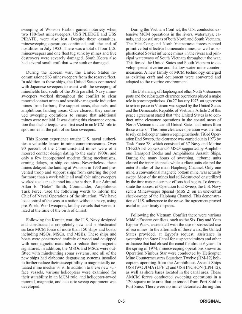
sweeping of Wonson Harbor gained notoriety whentwo 180-foot minesweepers, USS PLEDGE and USSPIRATE, were also lost. Despite these casualties,minesweeping operations continued until the end ofhostilities in July 1953. There was a total of four U.S.minesweepers and one fleet tug sunk by mines and fivedestroyers were severely damaged. South Korea alsohad several small craft that were sunk or damaged.
During the Korean war, the United States re-commissioned 63 minesweepers from the reserve fleet.In addition to these ships, the United States contractedwith Japanese sweepers to assist with the sweeping ofminefields laid south of the 38th parallel. Navy mine-sweepers worked throughout the conflict to clearmoored contact mines and sensitive magnetic inductionmines from harbors, fire support areas, channels, andamphibious landing areas. Once cleared, they contin-ued sweeping operations to ensure that additionalmines were not laid. It was during this clearance opera-tion that the helicopter was first used in an MCM role tospot mines in the path of surface sweepers.
This Korean experience taught U.S. naval authori-ties a valuable lesson in mine countermeasures. Over90 percent of the Communist-laid mines were of amoored contact design dating to the early 1900s, andonly a few incorporated modern firing mechanisms,arming delays, or ship counters. Nevertheless, thesemines delayed the landing at Wonson in 1950 and pre-vented troop and support ships from entering the portfor more than a week while all available minesweepersworked to clear a channel into the harbor. Rear AdmiralAllan E. “Hoke” Smith, Commander, AmphibiousTask Force, used the following words to inform theChief of Naval Operations of the situation: “We havelost control of the seas to a nation without a navy, usingpre-World War I weapons, laid by vessels that were uti-lized at the time of the birth of Christ.”
Following the Korean war, the U.S. Navy designedand constructed a completely new and sophisticatedsurface MCM force of more than 150 ships and boats,including MSOs, MSCs, and MSBs. These ships andboats were constructed entirely of wood and equippedwith nonmagnetic materials to reduce their magneticsignatures. In addition, the MSOs and MSCs were out-fitted with minehunting sonar systems, and all of thenew ships had elaborate degaussing systems installedto further reduce their susceptibility to magnetically ac-tuated mine mechanisms. In addition to these new sur-face vessels, various helicopters were examined fortheir suitability in an MCM role, and helicopter-towedmoored, magnetic, and acoustic sweep equipment wasdeveloped.
During the Vietnam Conflict, the U.S. conducted ex-tensive MCM operations in the rivers, waterways, ca-nals, and coastal areas of both North and South Vietnam.The Viet Cong and North Vietnamese forces plantedprimitive but effective homemade mines, as well as so-phisticated Soviet influence mines, in the rivers and prin-cipal waterways of South Vietnam throughout the war.This forced the United States and South Vietnam to de-velop special riverine and shallow water mine counter-measures. A new family of MCM technology emergedas existing craft and equipment were converted andadapted to the riverine environment.
The U.S. mining of Haiphong and other North Vietnameseports and the subsequent clearance operations played a majorrole in peace negotiations. On 27 January 1973, an agreementto restore peace in Vietnam was signed by the United Statesand the Democratic Republic of Vietnam. Article 2 of thispeace agreement stated that “the United States is to con-duct mine clearance operations in the coastal areas ofNorth Vietnam to clear all United States laid mines fromthose waters.” This mine clearance operation was the firstto rely on helicopter minesweeping methods. Titled Oper-ation End Sweep, the clearance was carried out in 1973 byTask Force 78, which consisted of 37 Navy and MarineCH-53A helicopters and 6 MSOs supported by Amphibi-ous Transport Docks and Amphibious Assault Ships.During the many hours of sweeping, airborne unitscleared the inner channels while surface units cleared theouter 3 miles of the main Haiphong Channel. Only onemine, a conventional magnetic bottom mine, was actuallyswept. Most of the mines had self-destructed or sterilizedby the time major clearance efforts had begun. To demon-strate the success of Operation End Sweep, the U.S. Navysent a Minesweeper Special (MSS 2) on an uneventfulcheck-sweep of the Haiphong Channel. This demonstra-tion of U.S. adherence to the cease-fire agreement proveduseful in later treaty disputes.
Following the Vietnam Conflict there were variousMiddle Eastern conflicts, such as the Six-Day and YomKippur Wars, associated with the use or suspected useof sea mines. In the aftermath of these wars, the UnitedStates provided, at Egypt’s request, assistance insweeping the Suez Canal for suspected mines and otherordnance that had closed the canal for almost 6 years. Inthe spring of 1974, minesweeping operations known asOperation Nimbus Star were conducted by HelicopterMine Countermeasures Squadron Twelve (HM-12) heli-copters operating from the Amphibious Assault ShipsUSS IWO JIMA (LPH 2) and USS INCHON (LPH 12),as well as shore bases located in the canal area. TheseAMCM forces conducted sweeping operations in a120-square mile area that extended from Port Said toPort Suez. There were no mines detonated during this
C-5 ORIGINAL
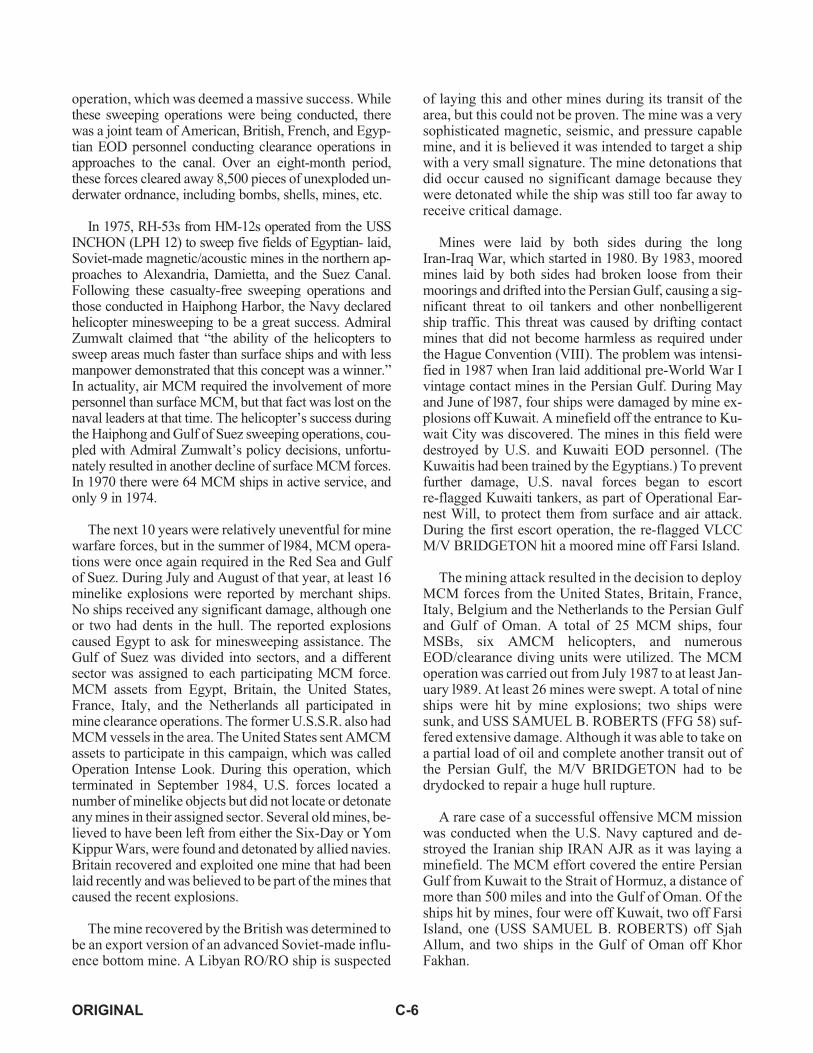
operation, which was deemed a massive success. Whilethese sweeping operations were being conducted, therewas a joint team of American, British, French, and Egyp-tian EOD personnel conducting clearance operations inapproaches to the canal. Over an eight-month period,these forces cleared away 8,500 pieces of unexploded un-derwater ordnance, including bombs, shells, mines, etc.
In 1975, RH-53s from HM-12s operated from the USSINCHON (LPH 12) to sweep five fields of Egyptian- laid,Soviet-made magnetic/acoustic mines in the northern ap-proaches to Alexandria, Damietta, and the Suez Canal.Following these casualty-free sweeping operations andthose conducted in Haiphong Harbor, the Navy declaredhelicopter minesweeping to be a great success. AdmiralZumwalt claimed that “the ability of the helicopters tosweep areas much faster than surface ships and with lessmanpower demonstrated that this concept was a winner.”In actuality, air MCM required the involvement of morepersonnel than surface MCM, but that fact was lost on thenaval leaders at that time. The helicopter’s success duringthe Haiphong and Gulf of Suez sweeping operations, cou-pled with Admiral Zumwalt’s policy decisions, unfortu-nately resulted in another decline of surface MCM forces.In 1970 there were 64 MCM ships in active service, andonly 9 in 1974.
The next 10 years were relatively uneventful for minewarfare forces, but in the summer of l984, MCM opera-tions were once again required in the Red Sea and Gulfof Suez. During July and August of that year, at least 16minelike explosions were reported by merchant ships.No ships received any significant damage, although oneor two had dents in the hull. The reported explosionscaused Egypt to ask for minesweeping assistance. TheGulf of Suez was divided into sectors, and a differentsector was assigned to each participating MCM force.MCM assets from Egypt, Britain, the United States,France, Italy, and the Netherlands all participated inmine clearance operations. The former U.S.S.R. also hadMCM vessels in the area. The United States sent AMCMassets to participate in this campaign, which was calledOperation Intense Look. During this operation, whichterminated in September 1984, U.S. forces located anumber of minelike objects but did not locate or detonateany mines in their assigned sector. Several old mines, be-lieved to have been left from either the Six-Day or YomKippur Wars, were found and detonated by allied navies.Britain recovered and exploited one mine that had beenlaid recently and was believed to be part of the mines thatcaused the recent explosions.
The mine recovered by the British was determined tobe an export version of an advanced Soviet-made influ-ence bottom mine. A Libyan RO/RO ship is suspected
of laying this and other mines during its transit of thearea, but this could not be proven. The mine was a verysophisticated magnetic, seismic, and pressure capablemine, and it is believed it was intended to target a shipwith a very small signature. The mine detonations thatdid occur caused no significant damage because theywere detonated while the ship was still too far away toreceive critical damage.
Mines were laid by both sides during the longIran-Iraq War, which started in 1980. By 1983, mooredmines laid by both sides had broken loose from theirmoorings and drifted into the Persian Gulf, causing a sig-nificant threat to oil tankers and other nonbelligerentship traffic. This threat was caused by drifting contactmines that did not become harmless as required underthe Hague Convention (VIII). The problem was intensi-fied in 1987 when Iran laid additional pre-World War Ivintage contact mines in the Persian Gulf. During Mayand June of l987, four ships were damaged by mine ex-plosions off Kuwait. A minefield off the entrance to Ku-wait City was discovered. The mines in this field weredestroyed by U.S. and Kuwaiti EOD personnel. (TheKuwaitis had been trained by the Egyptians.) To preventfurther damage, U.S. naval forces began to escortre-flagged Kuwaiti tankers, as part of Operational Ear-nest Will, to protect them from surface and air attack.During the first escort operation, the re-flagged VLCCM/V BRIDGETON hit a moored mine off Farsi Island.
The mining attack resulted in the decision to deployMCM forces from the United States, Britain, France,Italy, Belgium and the Netherlands to the Persian Gulfand Gulf of Oman. A total of 25 MCM ships, fourMSBs, six AMCM helicopters, and numerousEOD/clearance diving units were utilized. The MCMoperation was carried out from July 1987 to at least Jan-uary l989. At least 26 mines were swept. A total of nineships were hit by mine explosions; two ships weresunk, and USS SAMUEL B. ROBERTS (FFG 58) suf-fered extensive damage. Although it was able to take ona partial load of oil and complete another transit out ofthe Persian Gulf, the M/V BRIDGETON had to bedrydocked to repair a huge hull rupture.
A rare case of a successful offensive MCM missionwas conducted when the U.S. Navy captured and de-stroyed the Iranian ship IRAN AJR as it was laying aminefield. The MCM effort covered the entire PersianGulf from Kuwait to the Strait of Hormuz, a distance ofmore than 500 miles and into the Gulf of Oman. Of theships hit by mines, four were off Kuwait, two off FarsiIsland, one (USS SAMUEL B. ROBERTS) off SjahAllum, and two ships in the Gulf of Oman off KhorFakhan.
ORIGINAL C-6

Mine countermeasures played a prominent role in theoperations that were conducted in 1990 and 1991 byjoint allied naval forces during Operations Desert Shieldand Desert Storm. Iraqi forces planted an estimated1,300 sea mines in the Persian Gulf, ranging from simple(but deadly) moored contact types designed in the early1900s to some of the most modern types of magnetic andacoustic influence mines obtained from the SovietBloc and commercial sources in the free world. U.S.
MCM forces were part of the coalition MCM forces,which included air, surface and underwater MCMforces. These MCM forces conducted operations to lo-cate, sweep, and neutralize Iraqi weapons during bothwartime and the postwar period. The heavy damagesustained by two U.S. warships that struck Iraqi mines,USS PRINCETON (CG 59) and USS TRIPOLI (LPH10), generated considerable efforts to improve the U.S.Navy’s MCM capabilities.
C-7 (Reverse Blank) ORIGINAL

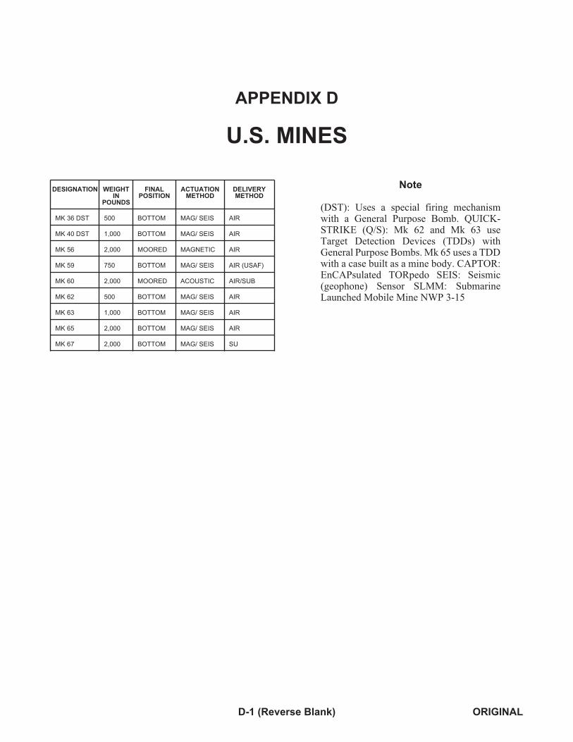
APPENDIX D
U.S. MINES
Note
(DST): Uses a special firing mechanismwith a General Purpose Bomb. QUICK-STRIKE (Q/S): Mk 62 and Mk 63 useTarget Detection Devices (TDDs) withGeneral Purpose Bombs. Mk 65 uses a TDDwith a case built as a mine body. CAPTOR:EnCAPsulated TORpedo SEIS: Seismic(geophone) Sensor SLMM: SubmarineLaunched Mobile Mine NWP 3-15
D-1 (Reverse Blank) ORIGINAL
DESIGNATION WEIGHTIN
POUNDS
FINALPOSITION
ACTUATIONMETHOD
DELIVERYMETHOD
MK 36 DST 500 BOTTOM MAG/ SEIS AIR
MK 40 DST 1,000 BOTTOM MAG/ SEIS AIR
MK 56 2,000 MOORED MAGNETIC AIR
MK 59 750 BOTTOM MAG/ SEIS AIR (USAF)
MK 60 2,000 MOORED ACOUSTIC AIR/SUB
MK 62 500 BOTTOM MAG/ SEIS AIR
MK 63 1,000 BOTTOM MAG/ SEIS AIR
MK 65 2,000 BOTTOM MAG/ SEIS AIR
MK 67 2,000 BOTTOM MAG/ SEIS SU

APPENDIX E
MIW References
E.1 GENERAL
This appendix provides a list (and in some cases abrief description) of publications that may be usefulfor further reference. U.S. references are groupedinto mining interest only, MCM interest only, andboth interest categories. Allied references are listedtogether because, in some cases, one volume is min-ing and the other is MCM (although many are of in-terest to both). Revision numbers have been omittedthroughout; the reader should ensure the current ver-sion of each publication is used. NWP 1-01 and theNTIC CD-ROM are sources of current edition infor-mation. Additionally, most NWPs and some otherpublications of interest can be found on theCD-ROM.
E.2 NAVY PUBLICATIONS FOR MINING
1. NWP 3-15.5 (formerly NWP 27-4), Mining Op-erations: Sets forth broad principles of mining.Describes planning factors, organization, execu-tion of mining operations, and actions requiredto marshal ordnance and delivery vehicles. De-scribes functional operation of U.S. mines.
2. NWP 3-15.51 (formerly NWP 27-5), MinefieldPlanning: Describes technical information andphilosophy to be considered in planning navalminefields. Documents Navy minefield plan-ning doctrine.
3. NWP 3-15.52 (formerly NWP 27-6), Mine Mk60 (CAPTOR) ASW Tactics: Provides detaileddescription of procedures and tactics for Mk 60CAPTOR mine employment.
4. MFPF 00, Minefield Planning Folder DoubleZero: Discusses the Uniform Mine WarfarePlanning System and provides detailed informa-tion on the content and availability of minefieldplanning folders.
5. OP 2637 Vol. I, Systems Descriptions & Opera-tional Characteristics of U.S. Naval Mines, Stand-
ard Naval Mines: This publication provides in-formation on the various user selectable settingsavailable on current U.S. mines.
6. OP 2637 Vol. II, Mine Setting Guide & Actua-tion & Damage Data (4 parts in separate covers):Data tables that the minefield planner uses to se-lect the appropriate mine type for a given sce-nario, as well as the sensitivity settings thatshould be used.
7. OP 2637 Vol III, Systems Descriptions & Oper-ational Characteristics of U.S. Naval Mines:Provides Secret data to supplement Unclassi-fied/Confidential information in volume I.
8. OP 2637 Vol V, Systems Descriptions & Opera-tional Characteristics of U.S. Naval Mines, Mk60 Mods 0 and 1
9. DIA Naval Order of Battle (area), Air Order ofBattle (area), and Electronic Order of Battle (area):Sources (3 separate pubs for each area) of intelli-gence used in minefield and mine delivery plan-ning. Where available, theater produced Orders ofBattle may be more up to date and should be used.
10. NWP 3-15.53 (formerly NWP 79-0-2), Subma-rine Special Operations Manual, Mining: Proce-dures and tactics for mine-laying by submarine.
E.3 PUBLICATIONS FOR MCM PLANNERS
1. NWP 3-15.1 (formerly NWP 27-1), Mine Coun-termeasures Operations: Overview and discus-sion of MCM concepts, procedures, andequipment.
2. NWP 3-15.11 (formerly NWP 27-2), SurfaceMine Countermeasures Operations: Detailed in-formation about SMCM platforms, equipment,operating procedures, and tactics.
3. NWP 3-15.12 (formerly NWP 27-3), Airborne MineCountermeasures Operations: Detailed information
E-1 ORIGINAL
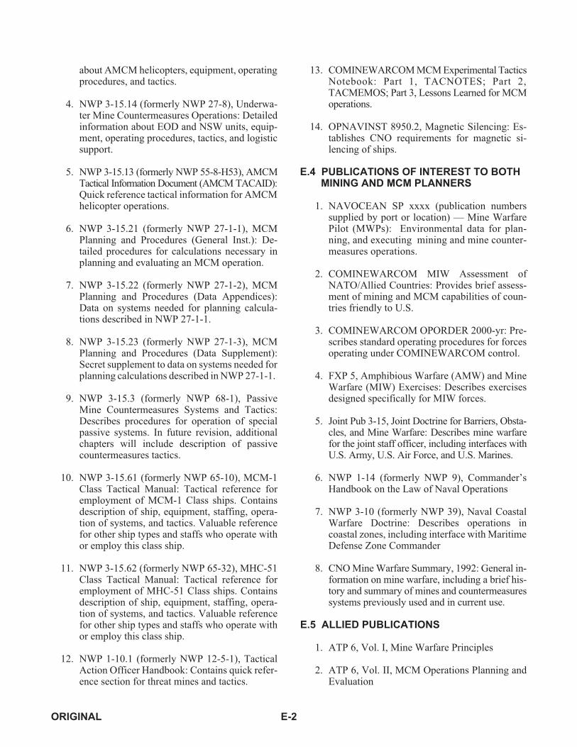
about AMCM helicopters, equipment, operatingprocedures, and tactics.
4. NWP 3-15.14 (formerly NWP 27-8), Underwa-ter Mine Countermeasures Operations: Detailedinformation about EOD and NSW units, equip-ment, operating procedures, tactics, and logisticsupport.
5. NWP 3-15.13 (formerly NWP 55-8-H53), AMCMTactical Information Document (AMCM TACAID):Quick reference tactical information for AMCMhelicopter operations.
6. NWP 3-15.21 (formerly NWP 27-1-1), MCMPlanning and Procedures (General Inst.): De-tailed procedures for calculations necessary inplanning and evaluating an MCM operation.
7. NWP 3-15.22 (formerly NWP 27-1-2), MCMPlanning and Procedures (Data Appendices):Data on systems needed for planning calcula-tions described in NWP 27-1-1.
8. NWP 3-15.23 (formerly NWP 27-1-3), MCMPlanning and Procedures (Data Supplement):Secret supplement to data on systems needed forplanning calculations described in NWP 27-1-1.
9. NWP 3-15.3 (formerly NWP 68-1), PassiveMine Countermeasures Systems and Tactics:Describes procedures for operation of specialpassive systems. In future revision, additionalchapters will include description of passivecountermeasures tactics.
10. NWP 3-15.61 (formerly NWP 65-10), MCM-1Class Tactical Manual: Tactical reference foremployment of MCM-1 Class ships. Containsdescription of ship, equipment, staffing, opera-tion of systems, and tactics. Valuable referencefor other ship types and staffs who operate withor employ this class ship.
11. NWP 3-15.62 (formerly NWP 65-32), MHC-51Class Tactical Manual: Tactical reference foremployment of MHC-51 Class ships. Containsdescription of ship, equipment, staffing, opera-tion of systems, and tactics. Valuable referencefor other ship types and staffs who operate withor employ this class ship.
12. NWP 1-10.1 (formerly NWP 12-5-1), TacticalAction Officer Handbook: Contains quick refer-ence section for threat mines and tactics.
13. COMINEWARCOM MCM Experimental TacticsNotebook: Part 1, TACNOTES; Part 2,TACMEMOS; Part 3, Lessons Learned for MCMoperations.
14. OPNAVINST 8950.2, Magnetic Silencing: Es-tablishes CNO requirements for magnetic si-lencing of ships.
E.4 PUBLICATIONS OF INTEREST TO BOTHMINING AND MCM PLANNERS
1. NAVOCEAN SP xxxx (publication numberssupplied by port or location) — Mine WarfarePilot (MWPs): Environmental data for plan-ning, and executing mining and mine counter-measures operations.
2. COMINEWARCOM MIW Assessment ofNATO/Allied Countries: Provides brief assess-ment of mining and MCM capabilities of coun-tries friendly to U.S.
3. COMINEWARCOM OPORDER 2000-yr: Pre-scribes standard operating procedures for forcesoperating under COMINEWARCOM control.
4. FXP 5, Amphibious Warfare (AMW) and MineWarfare (MIW) Exercises: Describes exercisesdesigned specifically for MIW forces.
5. Joint Pub 3-15, Joint Doctrine for Barriers, Obsta-cles, and Mine Warfare: Describes mine warfarefor the joint staff officer, including interfaces withU.S. Army, U.S. Air Force, and U.S. Marines.
6. NWP 1-14 (formerly NWP 9), Commander’sHandbook on the Law of Naval Operations
7. NWP 3-10 (formerly NWP 39), Naval CoastalWarfare Doctrine: Describes operations incoastal zones, including interface with MaritimeDefense Zone Commander
8. CNO Mine Warfare Summary, 1992: General in-formation on mine warfare, including a brief his-tory and summary of mines and countermeasuressystems previously used and in current use.
E.5 ALLIED PUBLICATIONS
1. ATP 6, Vol. I, Mine Warfare Principles
2. ATP 6, Vol. II, MCM Operations Planning andEvaluation
ORIGINAL E-2
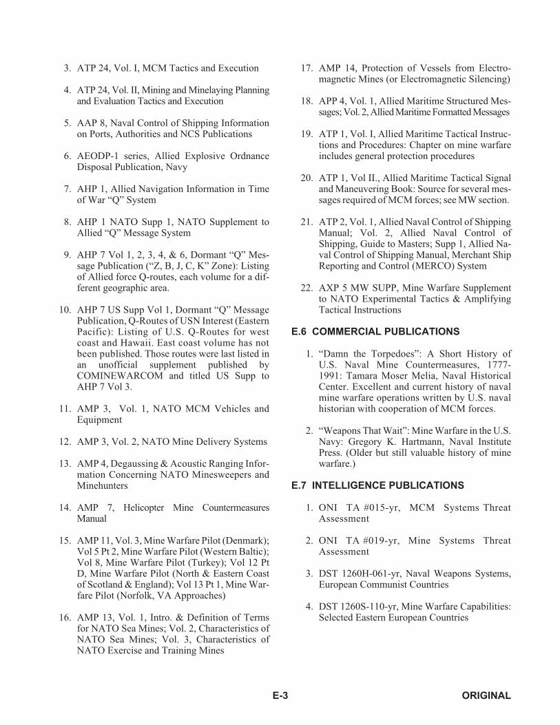
3. ATP 24, Vol. I, MCM Tactics and Execution
4. ATP 24, Vol. II, Mining and Minelaying Planningand Evaluation Tactics and Execution
5. AAP 8, Naval Control of Shipping Informationon Ports, Authorities and NCS Publications
6. AEODP-1 series, Allied Explosive OrdnanceDisposal Publication, Navy
7. AHP 1, Allied Navigation Information in Timeof War “Q” System
8. AHP 1 NATO Supp 1, NATO Supplement toAllied “Q” Message System
9. AHP 7 Vol 1, 2, 3, 4, & 6, Dormant “Q” Mes-sage Publication (“Z, B, J, C, K” Zone): Listingof Allied force Q-routes, each volume for a dif-ferent geographic area.
10. AHP 7 US Supp Vol 1, Dormant “Q” MessagePublication, Q-Routes of USN Interest (EasternPacific): Listing of U.S. Q-Routes for westcoast and Hawaii. East coast volume has notbeen published. Those routes were last listed inan unofficial supplement published byCOMINEWARCOM and titled US Supp toAHP 7 Vol 3.
11. AMP 3, Vol. 1, NATO MCM Vehicles andEquipment
12. AMP 3, Vol. 2, NATO Mine Delivery Systems
13. AMP 4, Degaussing & Acoustic Ranging Infor-mation Concerning NATO Minesweepers andMinehunters
14. AMP 7, Helicopter Mine CountermeasuresManual
15. AMP 11, Vol. 3, Mine Warfare Pilot (Denmark);Vol 5 Pt 2, Mine Warfare Pilot (Western Baltic);Vol 8, Mine Warfare Pilot (Turkey); Vol 12 PtD, Mine Warfare Pilot (North & Eastern Coastof Scotland & England); Vol 13 Pt 1, Mine War-fare Pilot (Norfolk, VA Approaches)
16. AMP 13, Vol. 1, Intro. & Definition of Termsfor NATO Sea Mines; Vol. 2, Characteristics ofNATO Sea Mines; Vol. 3, Characteristics ofNATO Exercise and Training Mines
17. AMP 14, Protection of Vessels from Electro-magnetic Mines (or Electromagnetic Silencing)
18. APP 4, Vol. 1, Allied Maritime Structured Mes-sages; Vol. 2, Allied Maritime Formatted Messages
19. ATP 1, Vol. I, Allied Maritime Tactical Instruc-tions and Procedures: Chapter on mine warfareincludes general protection procedures
20. ATP 1, Vol II., Allied Maritime Tactical Signaland Maneuvering Book: Source for several mes-sages required of MCM forces; see MW section.
21. ATP 2, Vol. 1, Allied Naval Control of ShippingManual; Vol. 2, Allied Naval Control ofShipping, Guide to Masters; Supp 1, Allied Na-val Control of Shipping Manual, Merchant ShipReporting and Control (MERCO) System
22. AXP 5 MW SUPP, Mine Warfare Supplementto NATO Experimental Tactics & AmplifyingTactical Instructions
E.6 COMMERCIAL PUBLICATIONS
1. “Damn the Torpedoes”: A Short History ofU.S. Naval Mine Countermeasures, 1777-1991: Tamara Moser Melia, Naval HistoricalCenter. Excellent and current history of navalmine warfare operations written by U.S. navalhistorian with cooperation of MCM forces.
2. “Weapons That Wait”: Mine Warfare in the U.S.Navy: Gregory K. Hartmann, Naval InstitutePress. (Older but still valuable history of minewarfare.)
E.7 INTELLIGENCE PUBLICATIONS
1. ONI TA #015-yr, MCM Systems ThreatAssessment
2. ONI TA #019-yr, Mine Systems ThreatAssessment
3. DST 1260H-061-yr, Naval Weapons Systems,European Communist Countries
4. DST 1260S-110-yr, Mine Warfare Capabilities:Selected Eastern European Countries
E-3 ORIGINAL

5. DST 1260S-120-yr, Naval Mines and MCM(Selected Free World & Third World Countries)
6. DST 1260H-071-yr, Naval Mine TechnicalCharacteristics Handbook
7. ONI 2660H-002-yr, Naval Mine RecognitionGuide
8. COMINEWARCOM Shipboard IntelligenceOfficer Handbook (CMWC ships/staff only)
9. COMINEWARCOM INST C3820.1 Pre-deployment Intelligence Support Collectionand Reporting
ORIGINAL E-4
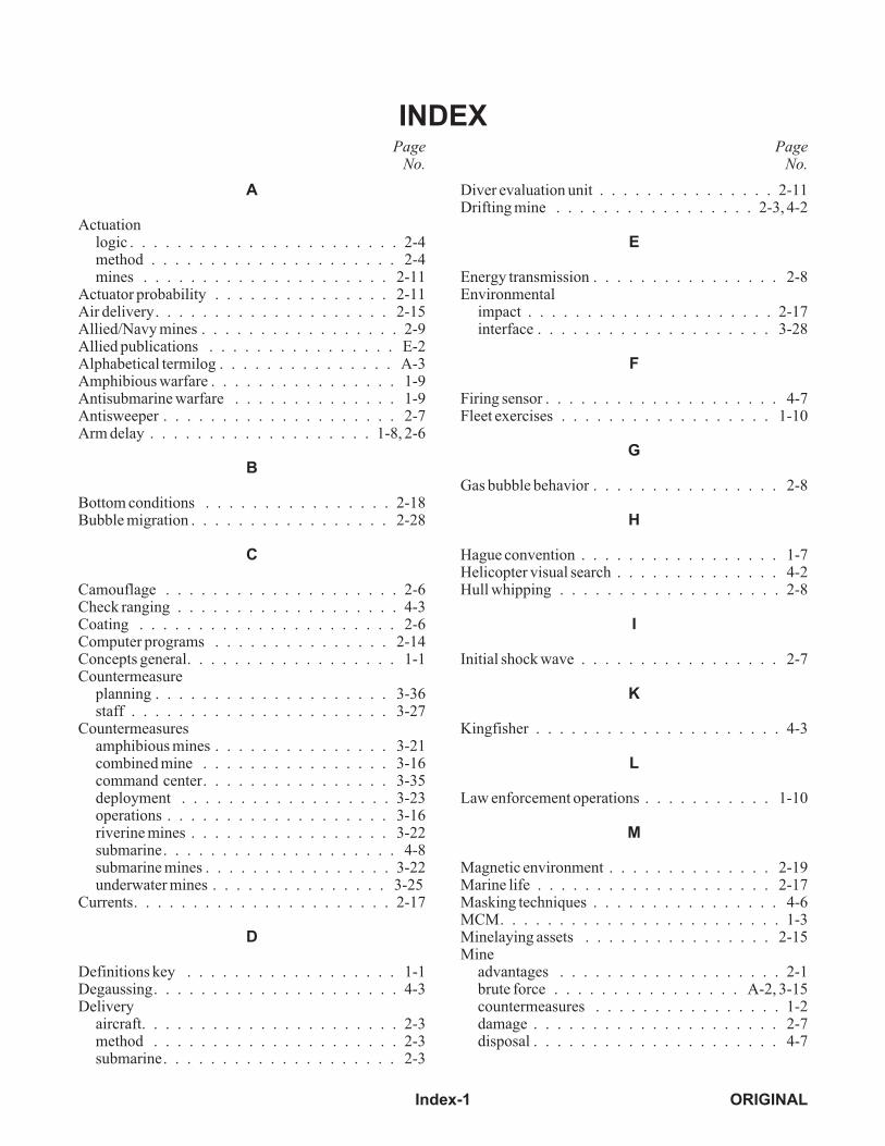
INDEX
A
Actuationlogic . . . . . . . . . . . . . . . . . . . . . . . 2-4method . . . . . . . . . . . . . . . . . . . . . 2-4mines . . . . . . . . . . . . . . . . . . . . . 2-11
Actuator probability . . . . . . . . . . . . . . . 2-11Air delivery. . . . . . . . . . . . . . . . . . . . 2-15Allied/Navy mines . . . . . . . . . . . . . . . . . 2-9Allied publications . . . . . . . . . . . . . . . . E-2Alphabetical termilog . . . . . . . . . . . . . . . A-3Amphibious warfare . . . . . . . . . . . . . . . . 1-9Antisubmarine warfare . . . . . . . . . . . . . . 1-9Antisweeper . . . . . . . . . . . . . . . . . . . . 2-7Arm delay . . . . . . . . . . . . . . . . . . . 1-8, 2-6
B
Bottom conditions . . . . . . . . . . . . . . . . 2-18Bubble migration . . . . . . . . . . . . . . . . . 2-28
C
Camouflage . . . . . . . . . . . . . . . . . . . . 2-6Check ranging . . . . . . . . . . . . . . . . . . . 4-3Coating . . . . . . . . . . . . . . . . . . . . . . 2-6Computer programs . . . . . . . . . . . . . . . 2-14Concepts general. . . . . . . . . . . . . . . . . . 1-1Countermeasure
planning . . . . . . . . . . . . . . . . . . . . 3-36staff . . . . . . . . . . . . . . . . . . . . . . 3-27
Countermeasuresamphibious mines . . . . . . . . . . . . . . . 3-21combined mine . . . . . . . . . . . . . . . . 3-16command center. . . . . . . . . . . . . . . . 3-35deployment . . . . . . . . . . . . . . . . . . 3-23operations . . . . . . . . . . . . . . . . . . . 3-16riverine mines . . . . . . . . . . . . . . . . . 3-22submarine. . . . . . . . . . . . . . . . . . . . 4-8submarine mines . . . . . . . . . . . . . . . . 3-22underwater mines . . . . . . . . . . . . . . . 3-25
Currents. . . . . . . . . . . . . . . . . . . . . . 2-17
D
Definitions key . . . . . . . . . . . . . . . . . . 1-1Degaussing. . . . . . . . . . . . . . . . . . . . . 4-3Delivery
aircraft. . . . . . . . . . . . . . . . . . . . . . 2-3method . . . . . . . . . . . . . . . . . . . . . 2-3submarine. . . . . . . . . . . . . . . . . . . . 2-3
Diver evaluation unit . . . . . . . . . . . . . . . 2-11Drifting mine . . . . . . . . . . . . . . . . . 2-3, 4-2
E
Energy transmission . . . . . . . . . . . . . . . . 2-8Environmental
impact . . . . . . . . . . . . . . . . . . . . . 2-17interface . . . . . . . . . . . . . . . . . . . . 3-28
F
Firing sensor . . . . . . . . . . . . . . . . . . . . 4-7Fleet exercises . . . . . . . . . . . . . . . . . . 1-10
G
Gas bubble behavior . . . . . . . . . . . . . . . . 2-8
H
Hague convention . . . . . . . . . . . . . . . . . 1-7Helicopter visual search . . . . . . . . . . . . . . 4-2Hull whipping . . . . . . . . . . . . . . . . . . . 2-8
I
Initial shock wave . . . . . . . . . . . . . . . . . 2-7
K
Kingfisher . . . . . . . . . . . . . . . . . . . . . 4-3
L
Law enforcement operations . . . . . . . . . . . 1-10
M
Magnetic environment . . . . . . . . . . . . . . 2-19Marine life . . . . . . . . . . . . . . . . . . . . 2-17Masking techniques . . . . . . . . . . . . . . . . 4-6MCM. . . . . . . . . . . . . . . . . . . . . . . . 1-3Minelaying assets . . . . . . . . . . . . . . . . 2-15Mine
advantages . . . . . . . . . . . . . . . . . . . 2-1brute force . . . . . . . . . . . . . . . . A-2, 3-15countermeasures . . . . . . . . . . . . . . . . 1-2damage . . . . . . . . . . . . . . . . . . . . . 2-7disposal . . . . . . . . . . . . . . . . . . . . . 4-7
Index-1 ORIGINAL
PageNo.
PageNo.
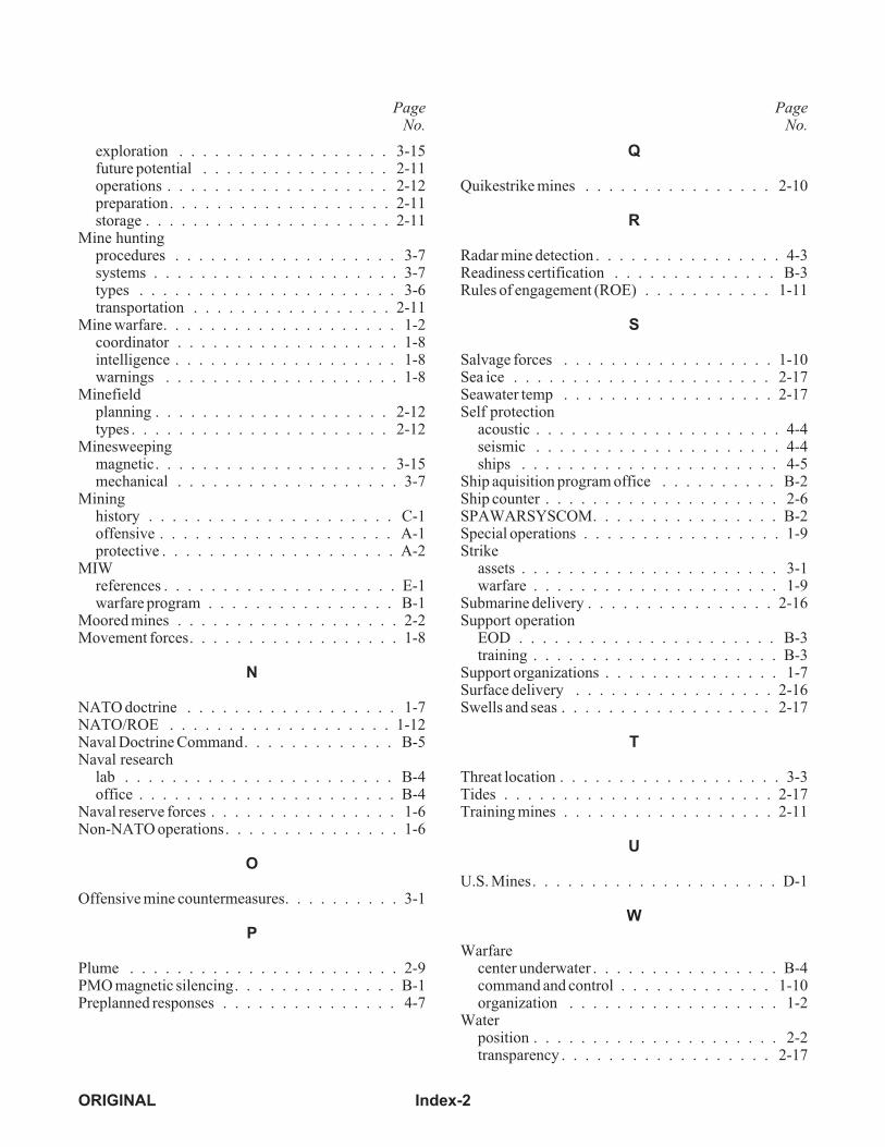
exploration . . . . . . . . . . . . . . . . . . 3-15future potential . . . . . . . . . . . . . . . . 2-11operations . . . . . . . . . . . . . . . . . . . 2-12preparation. . . . . . . . . . . . . . . . . . . 2-11storage . . . . . . . . . . . . . . . . . . . . . 2-11
Mine huntingprocedures . . . . . . . . . . . . . . . . . . . 3-7systems . . . . . . . . . . . . . . . . . . . . . 3-7types . . . . . . . . . . . . . . . . . . . . . . 3-6transportation . . . . . . . . . . . . . . . . . 2-11
Mine warfare. . . . . . . . . . . . . . . . . . . . 1-2coordinator . . . . . . . . . . . . . . . . . . . 1-8intelligence . . . . . . . . . . . . . . . . . . . 1-8warnings . . . . . . . . . . . . . . . . . . . . 1-8
Minefieldplanning . . . . . . . . . . . . . . . . . . . . 2-12types . . . . . . . . . . . . . . . . . . . . . . 2-12
Minesweepingmagnetic. . . . . . . . . . . . . . . . . . . . 3-15mechanical . . . . . . . . . . . . . . . . . . . 3-7
Mininghistory . . . . . . . . . . . . . . . . . . . . . C-1offensive . . . . . . . . . . . . . . . . . . . . A-1protective . . . . . . . . . . . . . . . . . . . . A-2
MIWreferences . . . . . . . . . . . . . . . . . . . . E-1warfare program . . . . . . . . . . . . . . . . B-1
Moored mines . . . . . . . . . . . . . . . . . . . 2-2Movement forces. . . . . . . . . . . . . . . . . . 1-8
N
NATO doctrine . . . . . . . . . . . . . . . . . . 1-7NATO/ROE . . . . . . . . . . . . . . . . . . . 1-12Naval Doctrine Command. . . . . . . . . . . . . B-5Naval research
lab . . . . . . . . . . . . . . . . . . . . . . . B-4office . . . . . . . . . . . . . . . . . . . . . . B-4
Naval reserve forces . . . . . . . . . . . . . . . . 1-6Non-NATO operations. . . . . . . . . . . . . . . 1-6
O
Offensive mine countermeasures. . . . . . . . . . 3-1
P
Plume . . . . . . . . . . . . . . . . . . . . . . . 2-9PMO magnetic silencing. . . . . . . . . . . . . . B-1Preplanned responses . . . . . . . . . . . . . . . 4-7
Q
Quikestrike mines . . . . . . . . . . . . . . . . 2-10
R
Radar mine detection . . . . . . . . . . . . . . . . 4-3Readiness certification . . . . . . . . . . . . . . B-3Rules of engagement (ROE) . . . . . . . . . . . 1-11
S
Salvage forces . . . . . . . . . . . . . . . . . . 1-10Sea ice . . . . . . . . . . . . . . . . . . . . . . 2-17Seawater temp . . . . . . . . . . . . . . . . . . 2-17Self protection
acoustic . . . . . . . . . . . . . . . . . . . . . 4-4seismic . . . . . . . . . . . . . . . . . . . . . 4-4ships . . . . . . . . . . . . . . . . . . . . . . 4-5
Ship aquisition program office . . . . . . . . . . B-2Ship counter . . . . . . . . . . . . . . . . . . . . 2-6SPAWARSYSCOM. . . . . . . . . . . . . . . . B-2Special operations . . . . . . . . . . . . . . . . . 1-9Strike
assets . . . . . . . . . . . . . . . . . . . . . . 3-1warfare . . . . . . . . . . . . . . . . . . . . . 1-9
Submarine delivery . . . . . . . . . . . . . . . . 2-16Support operation
EOD . . . . . . . . . . . . . . . . . . . . . . B-3training . . . . . . . . . . . . . . . . . . . . . B-3
Support organizations . . . . . . . . . . . . . . . 1-7Surface delivery . . . . . . . . . . . . . . . . . 2-16Swells and seas . . . . . . . . . . . . . . . . . . 2-17
T
Threat location . . . . . . . . . . . . . . . . . . . 3-3Tides . . . . . . . . . . . . . . . . . . . . . . . 2-17Training mines . . . . . . . . . . . . . . . . . . 2-11
U
U.S. Mines. . . . . . . . . . . . . . . . . . . . . D-1
W
Warfarecenter underwater . . . . . . . . . . . . . . . . B-4command and control . . . . . . . . . . . . . 1-10organization . . . . . . . . . . . . . . . . . . 1-2
Waterposition . . . . . . . . . . . . . . . . . . . . . 2-2transparency . . . . . . . . . . . . . . . . . . 2-17
ORIGINAL Index-2
PageNo.
PageNo.
LIST OF EFFECTIVE PAGES
LEP-1 (Reverse Blank) ORIGINAL
Effective Pages Page Numbers
Original
Original
Original
Original
Original
Original
Original
Original
Original
Original
Original
Original
Original
Original
Original
Original
1 (Reverse Blank)
3 (Reverse Blank)
5 (Reverse Blank)
7 thru 19 (Reverse Blank)
21 thru 23 (Reverse Blank)
1-1 thru 1-12
2-1 thru 2-19 (Reverse Blank)
3-1 thru 3-37 (Reverse Blank)
4-1 thru 4-8
A-1 thru A-15 (Reverse Blank)
B-1 thru B-5 (Reverse Blank)
C-1 thru C-7 (Reverse Blank)
D-1 (Reverse Blank)
E-1 thru E-4
Index-1, Index-2
LEP-1 (Reverse Blank)


NWP 3-15
MCWP 3-3.1.2