Embed Size (px)
Citation preview
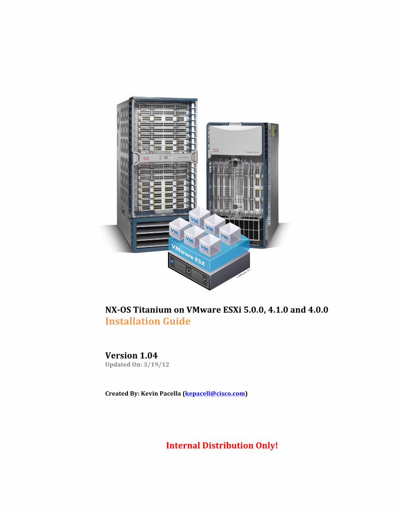
NX-‐OS Titanium on VMware ESXi 5.0.0, 4.1.0 and 4.0.0 Installation Guide Version 1.04 Updated On: 3/19/12 Created By: Kevin Pacella ([email protected])
Internal Distribution Only!
Cisco Confidential (Internal Use Only) Page 2 of 46 Last Modified 3/19/2012
Table of Contents Overview ...................................................................................................................................................................................... 3 NX-‐OS Titanium (What is it?) ......................................................................................................................................... 4 Server and Laptop/Desktop Requirements ............................................................................................................ 5 VMware ESXi Licensing .................................................................................................................................................... 5
VMware ESXi Server / NX-‐OS Titanium VM Installation Summary ................................................................... 6 1. Installation Prerequisites: ..................................................................................................................................... 6 2. VMware ESXi Server Installation: ........................................................................................................................... 6 3. NX-‐OS Titanium VM Installation: ........................................................................................................................ 6 4. Powering on the VM and Performing Basic Configuration: .................................................................... 6 5. Recommended VM Post Installation Steps: ................................................................................................... 6
1. Installation Prerequisites (Detailed) ..................................................................................................................... 7 Downloading VMware ESXi 4.1.0 (Build 260247) Server Software ............................................................. 7 Downloading NX-‐OS Titanium Images ...................................................................................................................... 7
2. VMware ESXi Server Installation (Detailed) ...................................................................................................... 8 Part I – VMware ESXi Server Installation ................................................................................................................. 8 Part II – Configuring the ESXi Management Parameters and vSphere Client (GUI) .............................. 8
3. NX-‐OS Titanium VM Installation (Detailed) ..................................................................................................... 10 Part I – Uploading the Titanium ISO image for the VM (Preparation) ....................................................... 10 Part II – Creating a new VM for the NX-‐OS Titanium OS .................................................................................. 11
4. Powering on the VM and Performing Basic Configuration ........................................................................ 20 5. Recommend VM Post Installation Steps ............................................................................................................. 23 Configure IP Address Information for “mgmt0” .................................................................................................. 23 Create a VM Snapshot ..................................................................................................................................................... 23
Network Connectivity Overview (ESXi vSwitch) ..................................................................................................... 24 Default Network / Interface Mapping ...................................................................................................................... 25 Modifying the VM ESXi Network Configuration .................................................................................................. 25 Creating a vSwitch and Moving NX-‐OS Titanium Interface Connections ................................................. 25 Basic Network Connectivity Example (2 NX-‐OS VM’s) ..................................................................................... 29 Configuring a vSwitch for Promiscuous Mode ..................................................................................................... 31
Summary .................................................................................................................................................................................... 32 Appendices: .............................................................................................................................................................................. 33 Appendix A: Document Change History .................................................................................................................. 33 Appendix B: VMware ESXi 4.0.0 (Build 208167) Console Port Connectivity Instructions ............... 33 Appendix C: VMware ESXi 5.0.0 (Build 469512) Console Port Connectivity Instructions ............... 42 Appendix D: Cisco UCS Hardware for VMware/NX-‐OS Titanium ................................................................ 46
Cisco Confidential (Internal Use Only) Page 3 of 46 Last Modified 3/19/2012
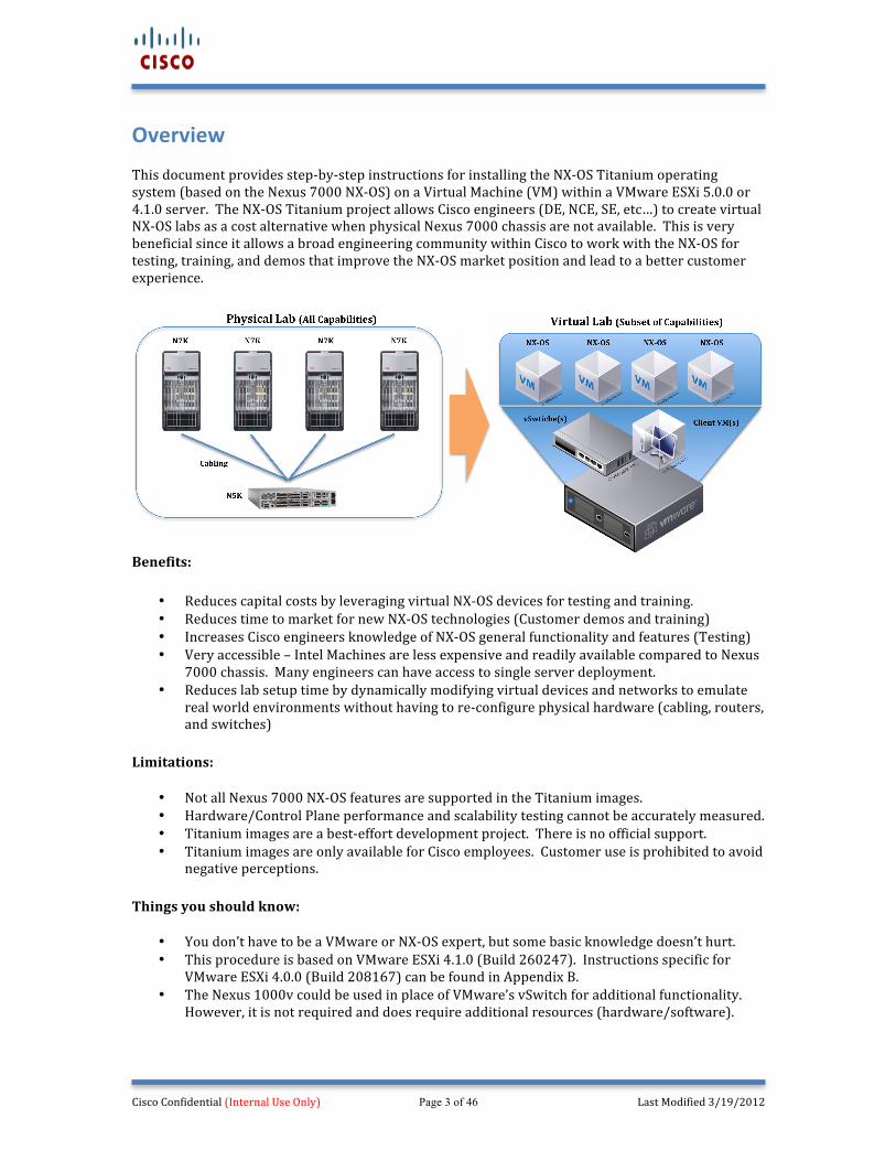
Overview This document provides step-‐by-‐step instructions for installing the NX-‐OS Titanium operating system (based on the Nexus 7000 NX-‐OS) on a Virtual Machine (VM) within a VMware ESXi 5.0.0 or 4.1.0 server. The NX-‐OS Titanium project allows Cisco engineers (DE, NCE, SE, etc…) to create virtual NX-‐OS labs as a cost alternative when physical Nexus 7000 chassis are not available. This is very beneficial since it allows a broad engineering community within Cisco to work with the NX-‐OS for testing, training, and demos that improve the NX-‐OS market position and lead to a better customer experience.
Benefits:
• Reduces capital costs by leveraging virtual NX-‐OS devices for testing and training. • Reduces time to market for new NX-‐OS technologies (Customer demos and training) • Increases Cisco engineers knowledge of NX-‐OS general functionality and features (Testing) • Very accessible – Intel Machines are less expensive and readily available compared to Nexus
7000 chassis. Many engineers can have access to single server deployment. • Reduces lab setup time by dynamically modifying virtual devices and networks to emulate
real world environments without having to re-‐configure physical hardware (cabling, routers, and switches)
Limitations:
• Not all Nexus 7000 NX-‐OS features are supported in the Titanium images. • Hardware/Control Plane performance and scalability testing cannot be accurately measured. • Titanium images are a best-‐effort development project. There is no official support. • Titanium images are only available for Cisco employees. Customer use is prohibited to avoid
negative perceptions. Things you should know:
• You don’t have to be a VMware or NX-‐OS expert, but some basic knowledge doesn’t hurt. • This procedure is based on VMware ESXi 4.1.0 (Build 260247). Instructions specific for
VMware ESXi 4.0.0 (Build 208167) can be found in Appendix B. • The Nexus 1000v could be used in place of VMware’s vSwitch for additional functionality.
However, it is not required and does require additional resources (hardware/software).
Cisco Confidential (Internal Use Only) Page 4 of 46 Last Modified 3/19/2012
NX-‐OS Titanium (What is it?) Titanium is for Internal use ONLY! Titanium is an NX-‐OS image built from the Nexus 7000 software train that contains a subset of protocols and features that can run on an Intel platform (i.e. laptop or server). Titanium is useful for testing and training purposes when a physical Nexus 7000 chassis is not available. Since Titanium can run on an Intel platform, it allows users to install Titanium virtual machines on their laptops for basic testing, or use dedicated server for more complex testing. It is important to remember that a Titanium image only supports a subset of the protocols and features available on a Nexus 7000 chassis. The following table summarizes some of the key protocols and features that are supported in the Titanium image. This is just a quick list and is not intended to be a definitive support matrix. Example of NX-‐OS Titanium Protocols and Features: Supported Not Supported
• Ipv4 and Ipv6 Routing • Virtual Routing Forwarding (VRF) Instances • Layer-‐3 Routing Protocols:
o BGP (MP-‐BGP) o EIGRP (Ipv4 & Ipv6) o ISIS o OSPF and OSPFv3 o RIPv2 o Static Routing (Ipv4 & Ipv6)
• Layer-‐3 Route Redistribution • Multicast Routing Protocols:
o IGMP / MLD o MSDP o PIM / PIM6
• First Hop Redundancy Protocols o GLBP o HSRP (Ipv4 & Ipv6) o VRRP
• Management/Security Protocols: o AAA (LDAP, RADIUS, TACACS+) o CDP and LLDP o NTP o SNMP o Syslog
• Overlay Transport Virtualization (OTV) • Pre-‐Release Features may be available:
o AMT o LISP
• Bi-‐Directional Forwarding (BFD) • Cisco TrustSec (Encryption) • HA – ISSU Software Upgrades • Layer-‐2 Switching (OTV is an exception) • Hardware (TCAM) Related Features:
o Access Control Lists (ACL’s) o Control Plane Policing (CoPP) o Quality of Service (QoS)
• Interface Counters • Port-‐Channel Interfaces (including vPC) • Port Security • Switched Virtual Interface (SVI) • Uni-‐Directional Link Detection (UDLD) • Virtual Device Context (VDC) • Q-‐in-‐Q Tunneling • 802.1x (dot.1x)
Note: Some features such as NAC, Netflow and Policy Based Routing (PBR) are configurable, but do not work. This may be useful for CLI verification.
Note 1: Titanium images do not require a license. The “grace-‐period” can be enabled for all supported protocols and features. Note 2: Hardware/Control Plane performance and scalability cannot be accurately measured. Note 3: First Hop Redundancy Protocols only support control-‐plane functionality; the data-‐plane does not forward traffic.
Cisco Confidential (Internal Use Only) Page 5 of 46 Last Modified 3/19/2012
Server and Laptop/Desktop Requirements The following two sections outline some brief hardware and software requirements required for completing the recommended procedure outlined in this document. It is recommended to review the ESXi 5.0.0 or 4.1.0 server requirements prior to purchasing server hardware. VMware ESXi servers are management by the vSphere client. Most laptops running a recent version of Microsoft Windows will be suitable to run the VMware vSphere client. Server Requirements The server hardware will determine how much mileage you get out of your configured system. Typically the more processing power (CPU) and memory (DRAM) you have, the more Virtual Machines (VMs) you can run simultaneously. Therefore, if you are going to provision a new server provision as much memory and CPU as your budget allows (Memory is more important than CPU). Although you can create a server using 2GB of DRAM, do not use less than 4 GB of DRAM for any installation. You should also have at least 1 NIC. This procedure was documented using the following hardware. However, a Cisco UCS server is now recommended – See Appendix D.
• SuperMicro X6DHR-‐8G2 (1 RU Server) • Intel Xeon 2.8Ghz (Single Core) • CD-‐ROM • 72 GB Hard Drive (This isn’t much capacity, but it works) • 8 GB of DRAM • 8 Ethernet Network Interfaces (10/100/1000) – You should have at least 1 NIC • VMware ESXi 4.1.0 (Build 260247) – See Appendix B: for specific instructions for ESXi 4.0.0
(Build 208167) Laptop/Desktop Requirements The laptop/desktop hardware shouldn’t be an issue as long as your machine is fairly new. The VMware vSphere client requires Microsoft Windows, but it can run as a virtual machine. This procedure was documented using the following laptop.
• Apple Macbook Pro (Intel I-‐5 with 4 GB of DRAM) • MAC-‐OS X 10.6.4 • VMware Fusion 3.0 • Windows 7 (32 bit) Virtual Machine (1 GB of DRAM) • vSphere Client 4.1.0 (Build 258902)
VMware ESXi Licensing This paper does not include the procedure required for licensing VMware ESXi 4.1.0 software. VMware licenses can be obtained from VMware, or more commonly from the Cisco Lab Resource Portal (CLRP), which provides Cisco employees with access to most VMware software free-‐of-‐charge for use in a controlled lab environment. If you do not license your ESXi server, your evaluation will last 60 days. To properly license your VMware ESXi implementation follow the instructions documented at the CLRP CEC web site @ http://wwwin-‐engineering.cisco.com/labs/licensing/index.shtml. Note: The CLRP requires VMware vCenter, which requires additional hardware and software resources. This document does not cover the vCenter installation process.
Cisco Confidential (Internal Use Only) Page 6 of 46 Last Modified 3/19/2012
VMware ESXi Server / NX-‐OS Titanium VM Installation Summary The following five sections summarize the steps recommended to install the VMware ESXi software and create a Virtual Machine (VM) that will run the NX-‐OS Titanium image. Step by step details will be provided in subsequent sections. The procedure for installing VMware ESXi 5.0.0, 4.1.0 and 4.0.0 are very similar with the exception of configuring the NX-‐OS Titanium VM console port. The console port configuration process is much easier in VMWare ESXi 5.0.0 and 4.1.0 due to the network serial port (URI) feature. Instructions for VMware 4.0.0 are included in Appendix B:
1. Installation Prerequisites:
• Obtain a copy of VMware Server ESXi 5.0.0 (Build 469512) or 4.1.0 (Build 260247) • Download a NX-‐OS Titanium ISO image to your laptop
2. VMware ESXi Server Installation:
1. Install VMware ESXi Server software 2. Install the vSphere client on your laptop and verify connectivity to the ESXi Server
See Appendix B: if VMware ESXi 4.0.0 is being installed. See Appendix C: if VMware ESXi 5.0.0 is being installed.
3. NX-‐OS Titanium VM Installation:
1. From the vSphere client, upload a NX-‐OS Titanium ISO image to the ESXi datastore (This only needs to be done once)
2. Using the vSphere client, create a new VM using the Virtual Machine Wizard 3. Select the “Custom” option and configure the VM using the detailed instructions provided in
this document 4. Click “Finish” to complete the VM installation
4. Powering on the VM and Performing Basic Configuration:
1. From the vSphere client, power on the VM from the VM’s “Getting Started” tab 2. When prompted on the VM Console, load the NX-‐OS Titanium “kickstart” image (The
vSphere client VM console will stop working after the system image starts to boot up) 3. Using a TELNET client, connect to the VM’s console 4. Configure the NX-‐OS startup script – The vSphere client VM console will start to work once
this step is completed 5. Configure the “kickstart” and “system” boot variables, save the configuration to memory and
reload the NX-‐OS
5. Recommended VM Post Installation Steps:
1. From the vSphere client, create a snapshot of the working VM with the base configuration 2. Configure an IP address and default gateway for the mgmt0 interface, so you can SSH to the
VM in the future without having to use the vSphere client VM console
Cisco Confidential (Internal Use Only) Page 7 of 46 Last Modified 3/19/2012
1. Installation Prerequisites (Detailed) Each of the following sections contains instructions that should be completed before starting the recommended installation procedure. Some steps are obviously required, but others will cost you time in the long run if you skip them. The procedures are very similar when installing VMware ESXi 5.0.0. See Appendix C to understand the different console connectivity requirements.
Downloading VMware ESXi 4.1.0 (Build 260247) Server Software Obtain a copy of the VMware ESXi 4.1.0 software. There are several places to get the software such as the VMware or Cisco Lab Resource Portal web sites. An ISO image is available at the following link to save you time. Unlicensed software can only be evaluated for 60 days.
Download Link: http://wwwin-‐engineering.cisco.com/labs/licensing/vmindex.shtml
Downloading NX-‐OS Titanium Images Titanium images are packaged as ISO files or as standard “kickstart” and “system” image files. ISO images are typically used during the creation of a VM, and the standard image files allow for software upgrades using the same procedure used when upgrading a physical Nexus 7000 chassis.
Naming Convention Examples: File Name File Description titanium-‐gdb.4.2.3.iso ISO image file that contains the “kickstart” and “system” images titanium-‐d1-‐kickstart-‐4.2.3.gbin 4.2(3) Kickstart image file titanium-‐d1.4.2.3.gbin 4.2(3) System image file
Download the “titanium-‐gdb.4.2.3.iso” image. Images are posted on the following Nexus 7000 wiki link. At this time there is not a systematic image posting update procedure, so don’t expect to see every image that has been posted on CCO.
Download Link: http://bock-‐bock.cisco.com/wiki/N7K:Titanium:images
Cisco Confidential (Internal Use Only) Page 8 of 46 Last Modified 3/19/2012
2. VMware ESXi Server Installation (Detailed) The following steps outline the detailed procedure recommended for installing VMware ESXi on a server. The steps have been grouped into four different parts that each have a common objective that allow for a quick and efficient installation. However, installation procedures may vary in the future as VMware may modify their software.
Part I – VMware ESXi Server Installation Part II – Configuring the ESXi Management Parameters and vSphere Client (GUI)
Part I – VMware ESXi Server Installation Step 1: Insert the VMware ESXi 4.1.0 (Build 260247) ISO CD into the CDROM and re-‐boot the server, so the server boots from the CD-‐ROM. The server BIOS may have to be modified to boot from the CD-‐ROM. Step 2: When prompted, press <enter> to install Step 3: When prompted, press <F11> to accept the Wmware license agreement. Step 4: Select a hard disk for the VMware installation menu and press <enter>. Press <enter> a second time when prompted to overwrite the existing contents of the selected disk. If you do not want to do this, press the <backspace> key to select another disk. Step 5: Confirm the install by pressing <F11> Step 6: When the ESXi file installation is complete, the installer will prompt you to remove the CD-‐ROM and press <enter> to reboot the server.
Part II – Configuring the ESXi Management Parameters and vSphere Client (GUI) Step1: After the system has booted up with ESXi, press <F2> to customize the system settings. Step 2: Configure a password for the “root” user by selecting “Configure Password” Step 3: Configure the management IP information by selecting “Configure Management Network” and selecting “IP Configuration” on the following menu. Select “Set static IP address and network configuration” and type in the IP address, subnet mask, and the default gateway. Exit out saving the changes. Step 4: Test the management network connectivity by selecting “Test Management Network”. Once selected, the default gateway should be automatically populated. Additional IP addresses can be tested as well. Press <enter> to verify basic IP network connectivity. If successful move on to the next step. Step 5: Press <ESC> to log out and put the server back on the main menu screen.
Cisco Confidential (Internal Use Only) Page 9 of 46 Last Modified 3/19/2012
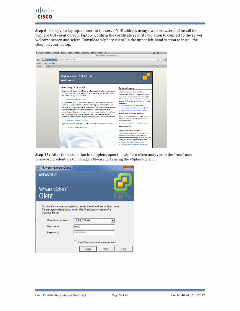
Step 6: Using your laptop, connect to the server’s IP address using a web browser and install the vSphere GUI client on your laptop. Confirm the certificate security violation to connect to the server welcome screen and select “Download vSphere client” in the upper left-‐hand section to install the client on your laptop.
Step 13: After the installation is complete, open the vSphere client and type in the “root” user password credentials to manage VMware ESXi using the vSphere client.
Cisco Confidential (Internal Use Only) Page 10 of 46 Last Modified 3/19/2012
3. NX-‐OS Titanium VM Installation (Detailed) The following steps outline the detailed procedure recommended for creating a NX-‐OS Titanium VM. For best results, all of the previous steps outlined in the VMware Server Installation (Detailed) section should have been performed successfully. This section is divided into two parts. Part I – Uploading the Titanium ISO image for the VM (Preparation) Part II – Creating a new VM for the NX-‐OS Titanium OS
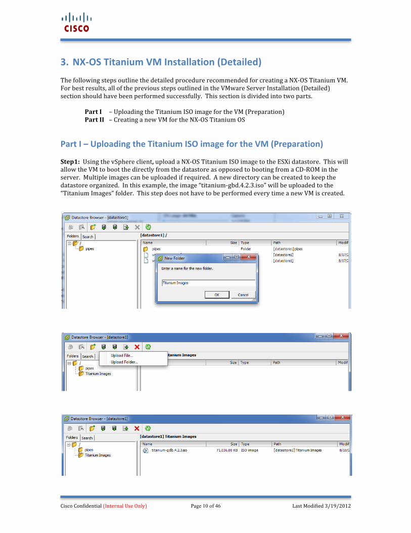
Part I – Uploading the Titanium ISO image for the VM (Preparation) Step1: Using the vSphere client, upload a NX-‐OS Titanium ISO image to the ESXi datastore. This will allow the VM to boot the directly from the datastore as opposed to booting from a CD-‐ROM in the server. Multiple images can be uploaded if required. A new directory can be created to keep the datastore organized. In this example, the image “titanium-‐gbd.4.2.3.iso” will be uploaded to the “Titanium Images” folder. This step does not have to be performed every time a new VM is created.
Cisco Confidential (Internal Use Only) Page 11 of 46 Last Modified 3/19/2012
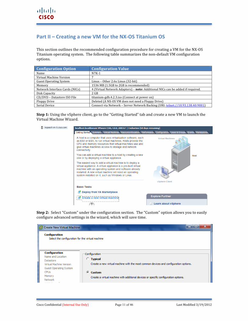
Part II – Creating a new VM for the NX-‐OS Titanium OS This section outlines the recommended configuration procedure for creating a VM for the NX-‐OS Titanium operating system. The following table summarizes the non-‐default VM configuration options. Configuration Option Configuration Value Name N7K-‐1 Virtual Machine Version 7 Guest Operating System Linux – Other 2.6x Linux (32-‐bit) Memory 1536 MB (1.5GB to 2GB is recommended) Network Interface Cards (NICs) 4 (Virtual Network Adapters) – note: Additional NICs can be added if required. Disk Capacity 2 GB CD/DVD – Datastore ISO File titanium-‐gdb.4.2.3.iso (Connect at power on) Floppy Drive Deleted (A NX-‐OS VM does not need a Floppy Drive) Serial Device Connect via Network – Server Network Backing (URI: telnet://10.93.138.40:9001) Step 1: Using the vSphere client, go to the “Getting Started” tab and create a new VM to launch the Virtual Machine Wizard.
Step 2: Select “Custom” under the configuration section. The “Custom” option allows you to easily configure advanced settings in the wizard, which will save time.
Cisco Confidential (Internal Use Only) Page 12 of 46 Last Modified 3/19/2012
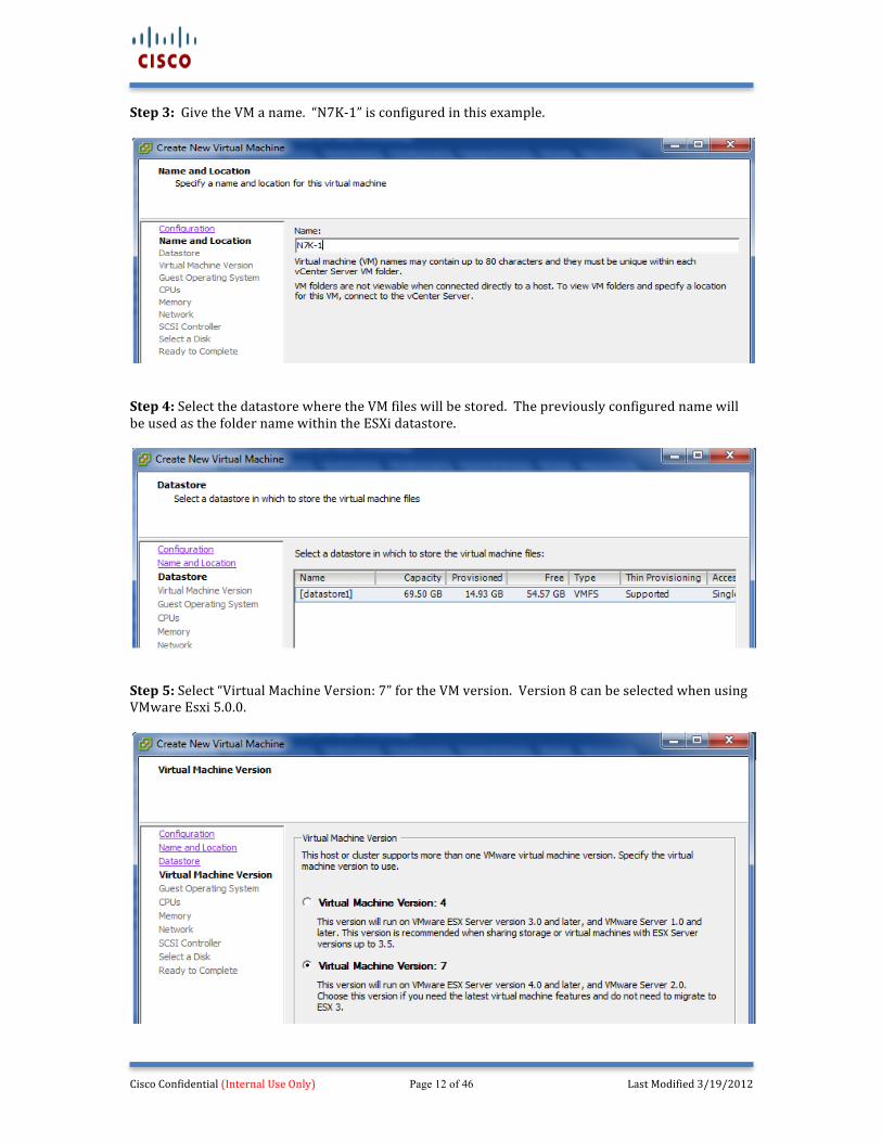
Step 3: Give the VM a name. “N7K-‐1” is configured in this example.
Step 4: Select the datastore where the VM files will be stored. The previously configured name will be used as the folder name within the ESXi datastore.
Step 5: Select “Virtual Machine Version: 7” for the VM version. Version 8 can be selected when using VMware Esxi 5.0.0.
Cisco Confidential (Internal Use Only) Page 13 of 46 Last Modified 3/19/2012
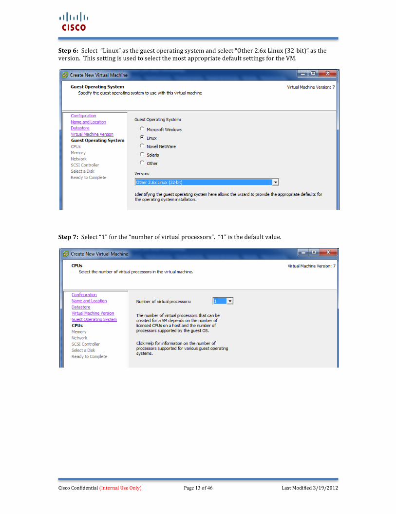
Step 6: Select “Linux” as the guest operating system and select “Other 2.6x Linux (32-‐bit)” as the version. This setting is used to select the most appropriate default settings for the VM.
Step 7: Select “1” for the “number of virtual processors”. “1” is the default value.
Cisco Confidential (Internal Use Only) Page 14 of 46 Last Modified 3/19/2012
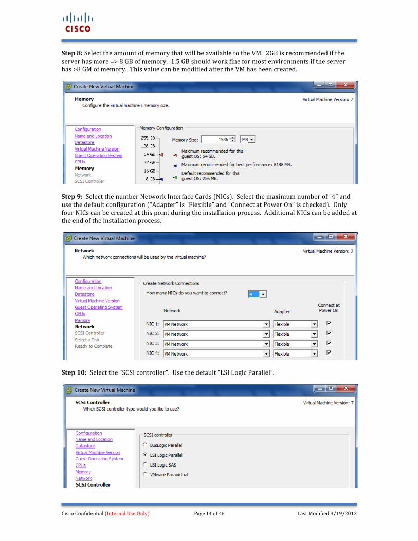
Step 8: Select the amount of memory that will be available to the VM. 2GB is recommended if the server has more => 8 GB of memory. 1.5 GB should work fine for most environments if the server has >8 GM of memory. This value can be modified after the VM has been created.
Step 9: Select the number Network Interface Cards (NICs). Select the maximum number of “4” and use the default configuration (“Adapter” is “Flexible” and “Connect at Power On” is checked). Only four NICs can be created at this point during the installation process. Additional NICs can be added at the end of the installation process.
Step 10: Select the “SCSI controller”. Use the default “LSI Logic Parallel”.
Cisco Confidential (Internal Use Only) Page 15 of 46 Last Modified 3/19/2012
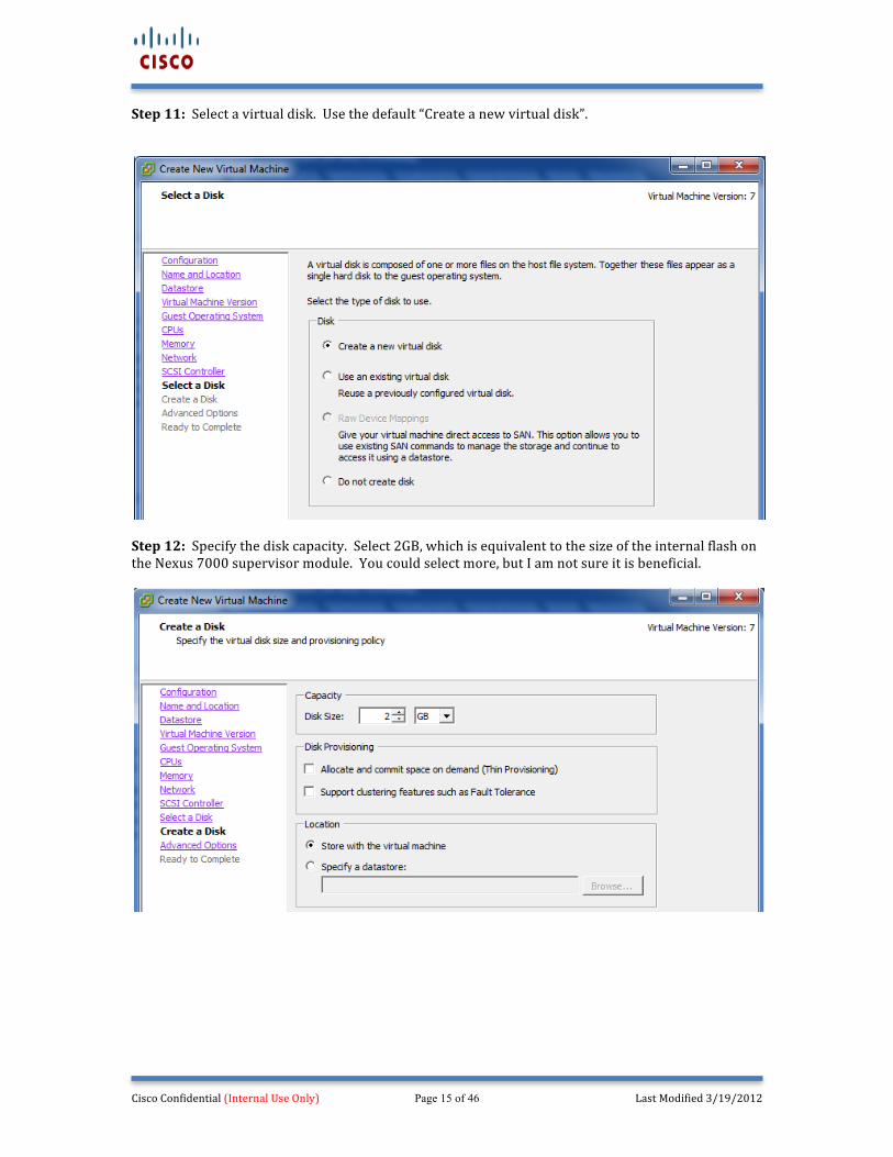
Step 11: Select a virtual disk. Use the default “Create a new virtual disk”.
Step 12: Specify the disk capacity. Select 2GB, which is equivalent to the size of the internal flash on the Nexus 7000 supervisor module. You could select more, but I am not sure it is beneficial.
Cisco Confidential (Internal Use Only) Page 16 of 46 Last Modified 3/19/2012
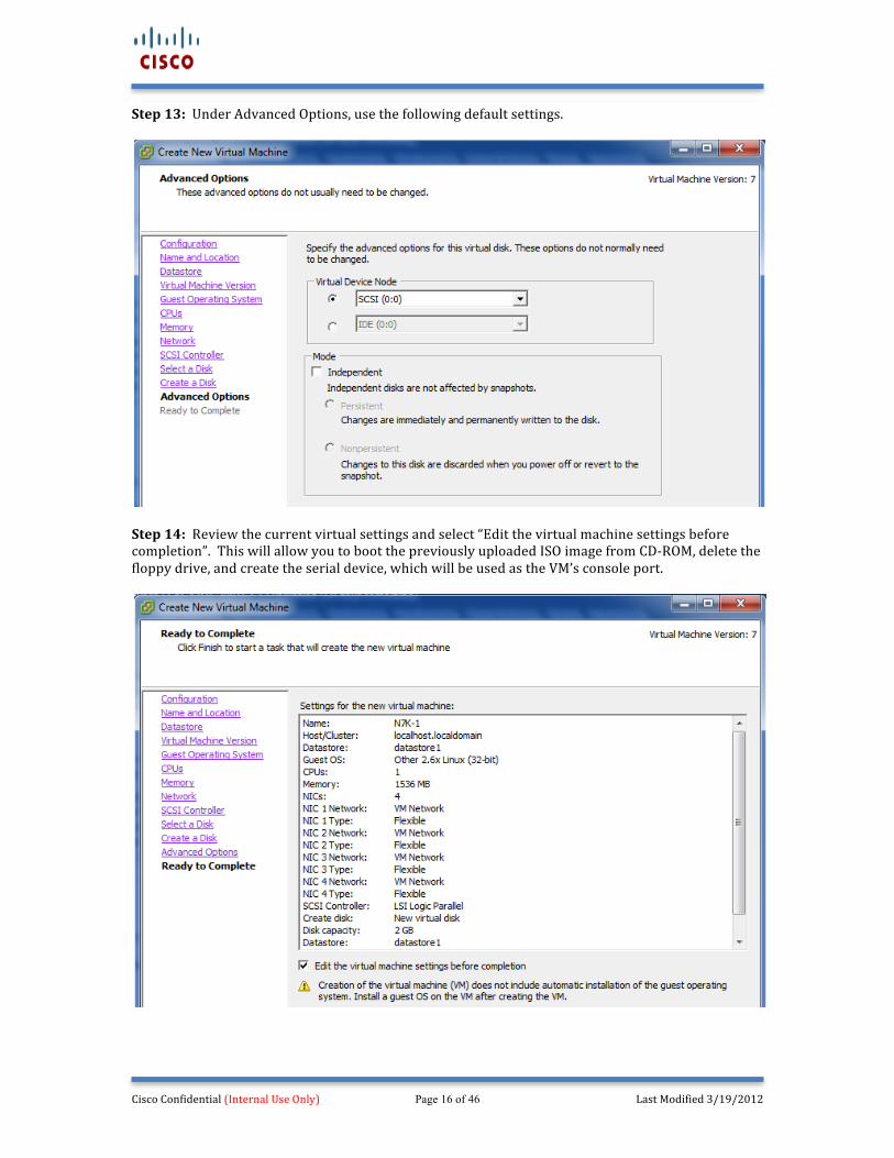
Step 13: Under Advanced Options, use the following default settings.
Step 14: Review the current virtual settings and select “Edit the virtual machine settings before completion”. This will allow you to boot the previously uploaded ISO image from CD-‐ROM, delete the floppy drive, and create the serial device, which will be used as the VM’s console port.
Cisco Confidential (Internal Use Only) Page 17 of 46 Last Modified 3/19/2012
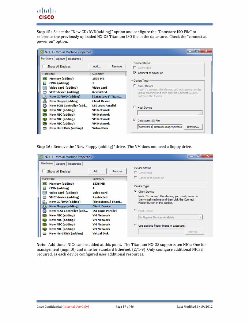
Step 15: Select the “New CD/DVD(adding)” option and configure the “Datastore ISO File” to reference the previously uploaded NX-‐OS Titanium ISO file in the datastore. Check the “connect at power on” option.
Step 16: Remove the “New Floppy (adding)” drive. The VM does not need a floppy drive.
Note: Additional NICs can be added at this point. The Titanium NX-‐OS supports ten NICs: One for management (mgmt0) and nine for standard Ethernet. (2/1-‐9) Only configure additional NICs if required, as each device configured uses additional resources.
Cisco Confidential (Internal Use Only) Page 18 of 46 Last Modified 3/19/2012
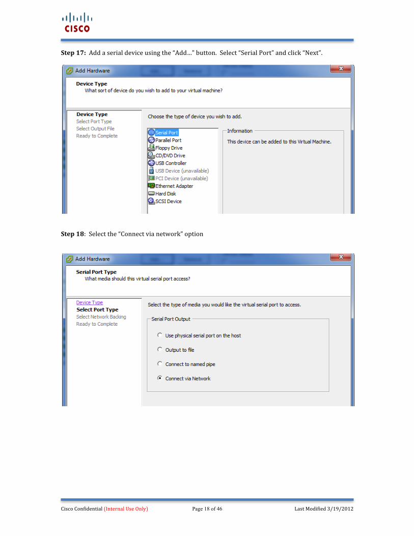
Step 17: Add a serial device using the “Add…” button. Select “Serial Port” and click “Next”.
Step 18: Select the “Connect via network” option
Cisco Confidential (Internal Use Only) Page 19 of 46 Last Modified 3/19/2012
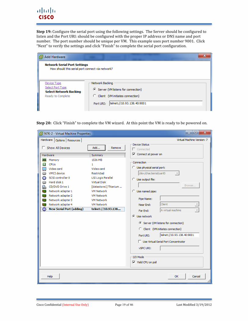
Step 19: Configure the serial port using the following settings. The Server should be configured to listen and the Port URI: should be configured with the proper IP address or DNS name and port number. The port number should be unique per VM. This example uses port number 9001. Click “Next” to verify the settings and click “Finish” to complete the serial port configuration.
Step 20: Click “Finish” to complete the VM wizard. At this point the VM is ready to be powered on.
Cisco Confidential (Internal Use Only) Page 20 of 46 Last Modified 3/19/2012
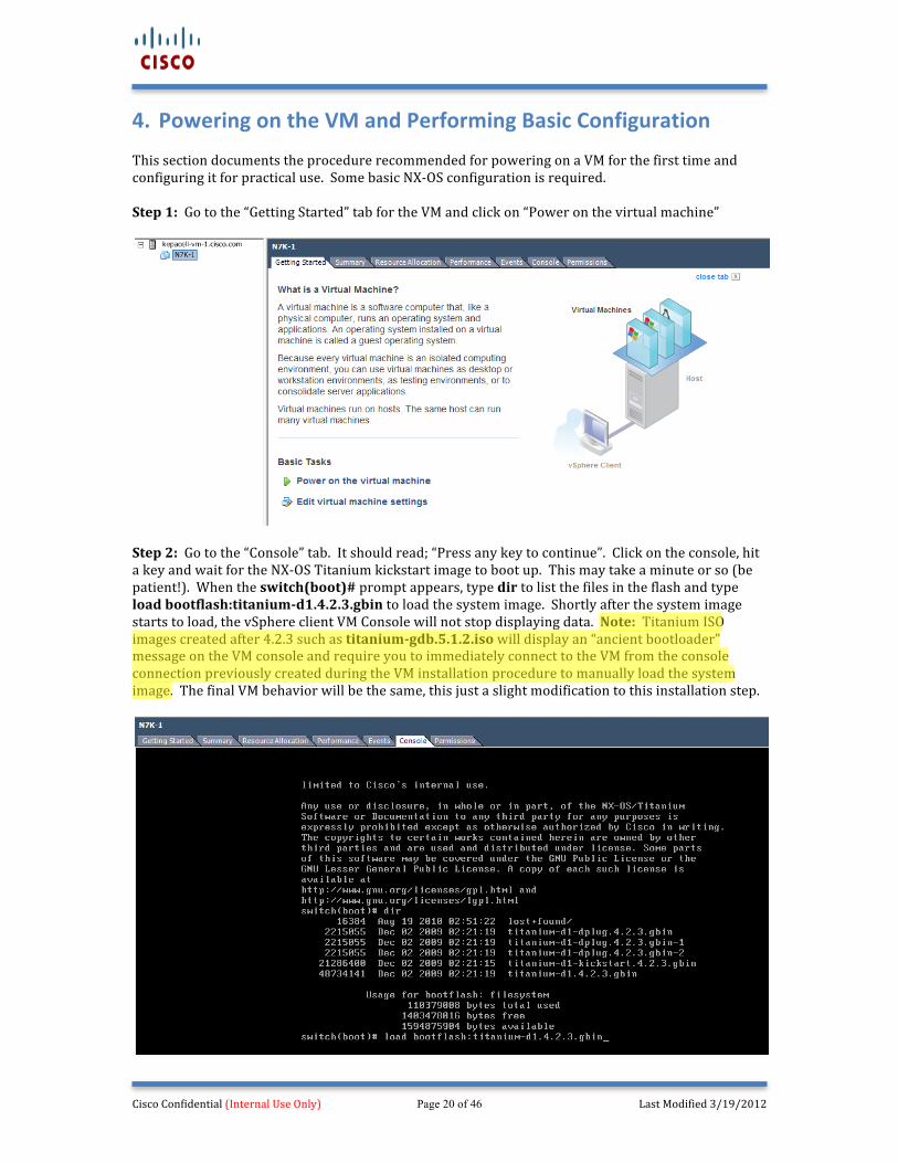
4. Powering on the VM and Performing Basic Configuration This section documents the procedure recommended for powering on a VM for the first time and configuring it for practical use. Some basic NX-‐OS configuration is required. Step 1: Go to the “Getting Started” tab for the VM and click on “Power on the virtual machine”
Step 2: Go to the “Console” tab. It should read; “Press any key to continue”. Click on the console, hit a key and wait for the NX-‐OS Titanium kickstart image to boot up. This may take a minute or so (be patient!). When the switch(boot)# prompt appears, type dir to list the files in the flash and type load bootflash:titanium-‐d1.4.2.3.gbin to load the system image. Shortly after the system image starts to load, the vSphere client VM Console will not stop displaying data. Note: Titanium ISO images created after 4.2.3 such as titanium-‐gdb.5.1.2.iso will display an “ancient bootloader” message on the VM console and require you to immediately connect to the VM from the console connection previously created during the VM installation procedure to manually load the system image. The final VM behavior will be the same, this just a slight modification to this installation step.
Cisco Confidential (Internal Use Only) Page 21 of 46 Last Modified 3/19/2012
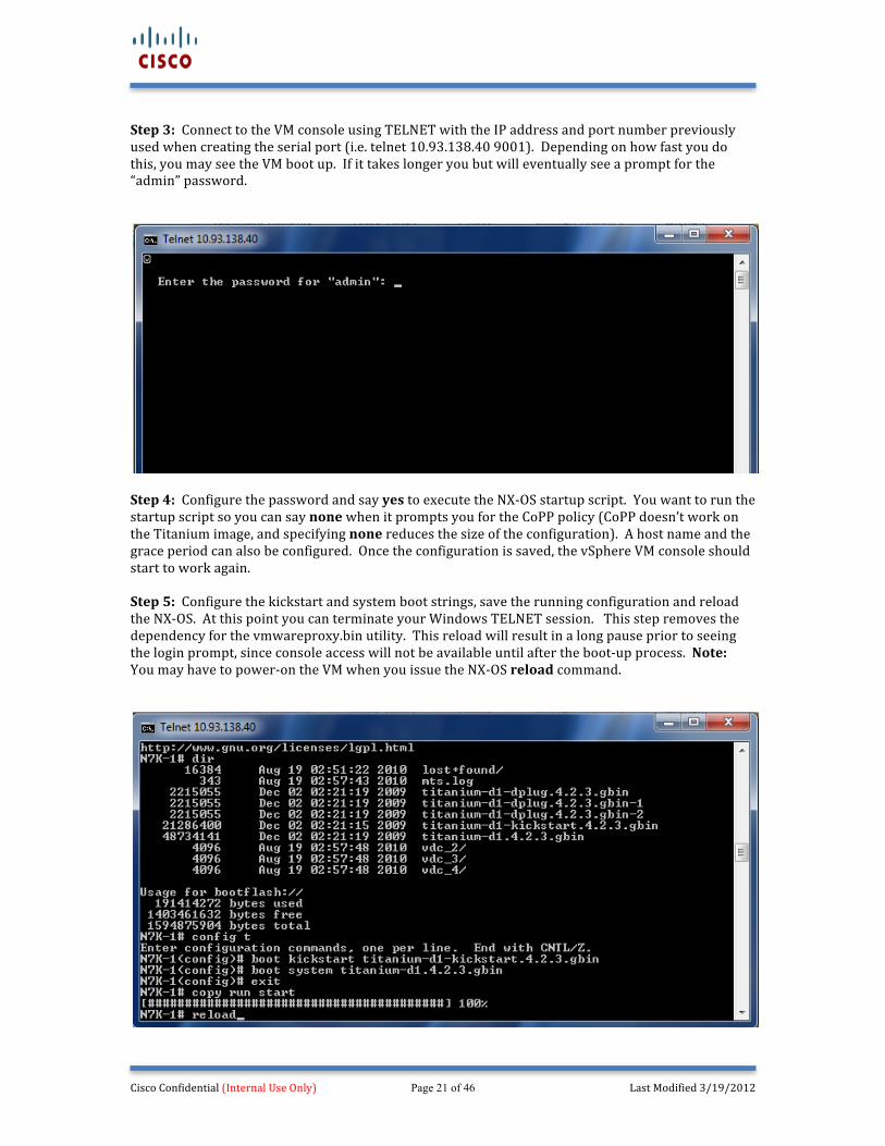
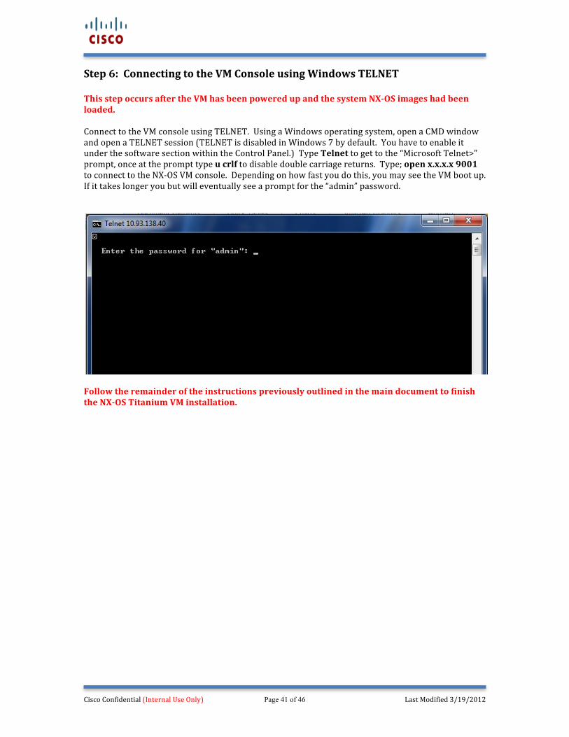
Step 3: Connect to the VM console using TELNET with the IP address and port number previously used when creating the serial port (i.e. telnet 10.93.138.40 9001). Depending on how fast you do this, you may see the VM boot up. If it takes longer you but will eventually see a prompt for the “admin” password.
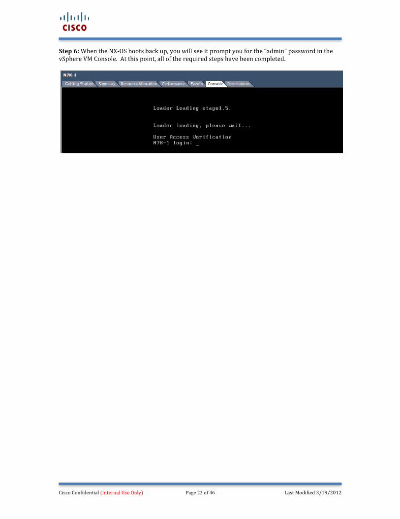
Step 4: Configure the password and say yes to execute the NX-‐OS startup script. You want to run the startup script so you can say none when it prompts you for the CoPP policy (CoPP doesn’t work on the Titanium image, and specifying none reduces the size of the configuration). A host name and the grace period can also be configured. Once the configuration is saved, the vSphere VM console should start to work again. Step 5: Configure the kickstart and system boot strings, save the running configuration and reload the NX-‐OS. At this point you can terminate your Windows TELNET session. This step removes the dependency for the vmwareproxy.bin utility. This reload will result in a long pause prior to seeing the login prompt, since console access will not be available until after the boot-‐up process. Note: You may have to power-‐on the VM when you issue the NX-‐OS reload command.
Cisco Confidential (Internal Use Only) Page 22 of 46 Last Modified 3/19/2012
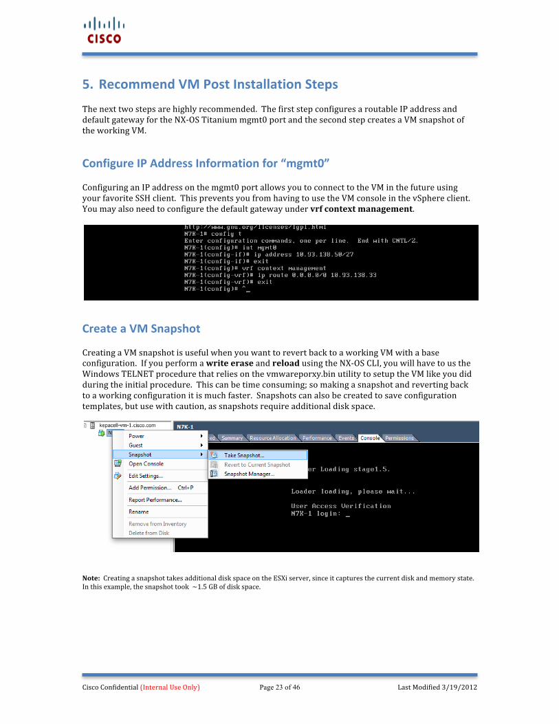
Step 6: When the NX-‐OS boots back up, you will see it prompt you for the “admin” password in the vSphere VM Console. At this point, all of the required steps have been completed.
Cisco Confidential (Internal Use Only) Page 23 of 46 Last Modified 3/19/2012
5. Recommend VM Post Installation Steps The next two steps are highly recommended. The first step configures a routable IP address and default gateway for the NX-‐OS Titanium mgmt0 port and the second step creates a VM snapshot of the working VM.
Configure IP Address Information for “mgmt0” Configuring an IP address on the mgmt0 port allows you to connect to the VM in the future using your favorite SSH client. This prevents you from having to use the VM console in the vSphere client. You may also need to configure the default gateway under vrf context management.
Create a VM Snapshot Creating a VM snapshot is useful when you want to revert back to a working VM with a base configuration. If you perform a write erase and reload using the NX-‐OS CLI, you will have to us the Windows TELNET procedure that relies on the vmwareporxy.bin utility to setup the VM like you did during the initial procedure. This can be time consuming; so making a snapshot and reverting back to a working configuration it is much faster. Snapshots can also be created to save configuration templates, but use with caution, as snapshots require additional disk space.
Note: Creating a snapshot takes additional disk space on the ESXi server, since it captures the current disk and memory state. In this example, the snapshot took ~1.5 GB of disk space.
Cisco Confidential (Internal Use Only) Page 24 of 46 Last Modified 3/19/2012
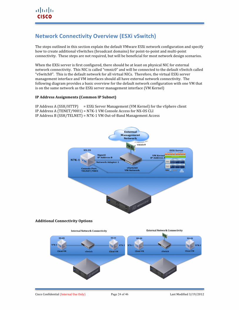
Network Connectivity Overview (ESXi vSwitch) The steps outlined in this section explain the default VMware ESXi network configuration and specify how to create additional vSwitches (broadcast domains) for point-‐to-‐point and multi-‐point connectivity. These steps are not required, but will be beneficial for most network design scenarios. When the EXSi server is first configured, there should be at least on physical NIC for external network connectivity. This NIC is called “vmnic0” and will be connected to the default vSwitch called “vSwitch0”. This is the default network for all virtual NICs. Therefore, the virtual ESXi server management interface and VM interfaces should all have external network connectivity. The following diagram provides a basic overview for the default network configuration with one VM that is on the same network as the ESXi server management interface (VM Kernel) IP Address Assignments (Common IP Subnet) IP Address A (SSH/HTTP) = ESXi Server Management (VM Kernel) for the vSphere client IP Address A (TENET/9001) = N7K-‐1 VM Console Access for NX-‐OS CLI IP Address B (SSH/TELNET) = N7K-‐1 VM Out-‐of-‐Band Management Access
Additional Connectivity Options
Cisco Confidential (Internal Use Only) Page 25 of 46 Last Modified 3/19/2012
Default Network / Interface Mapping The following table displays the default NX-‐OS Titanium VM/VMware ESXi interface/vSwitch mapping. The NX-‐OS will show 10 interfaces in its configuration, but only four of them will be enabled using the installation procedure documented in the previous section. (Six additional NICs can be configured for a total of ten). All usable interfaces are connected to “vSwitch0”, in the “VM Network” port group and associated to the physical “vmnic0” network interface. Therefore, all interfaces are in the same broadcast domain. This configuration will work for basic network designs, but will need to be modified if more complex design scenarios are required. Physical NICs in the ESXi server are labeled “vmic#”, so if you have 8 physical NICs they will be labeled “vmnic0 – vmnic7”. By default all VM virtual Network Adapters are connected to “vSwitch0 – VM Network”, which is connected to “vmnic0”. Therefore the NX-‐OS “Mgmt0” will have external connectivity by default. NX-‐OS Titanium (Int.) VM (NIC) ESXi Virtual Switch
(vSwitch) ESXi vSwitch Network
ESXi Physical NIC
Mgmt0 Network adapter 1 vSwitch0 VM Network
vmnic0 Ethernet 2/1 Network adapter 2 vSwtich0 VM Network Ethernet 2/2 Network adapter 3 vSwitch0 VM Network Ethernet 2/3 Network adapter 4 vSwitch0 VM Network Ethernet 2/4 – 2/9 Six additional NICs can be configured per VM (Only enable if required to preserve resources).
Modifying the VM ESXi Network Configuration It may be beneficial to isolate interfaces in their own broadcast domains. It is recommended to leave the NX-‐OS Titanium “mgmt0” port connected to vSwitch0, and move the other three interfaces into a new Virtual Switch such as “vSwitch1”. This isolates the management interface from the other interfaces. Additional vSwitches can be configured to create point-‐to-‐point and multi-‐point broadcast domains in the future to meet a wide range of network connectivity requirements.
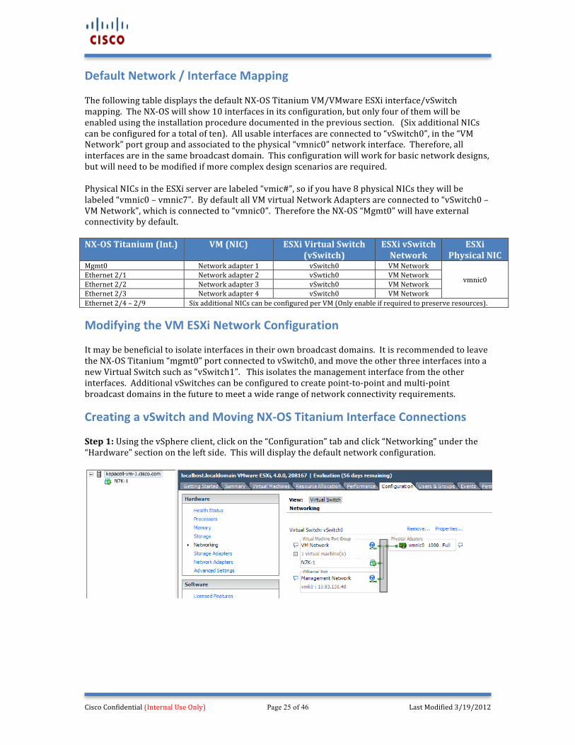
Creating a vSwitch and Moving NX-‐OS Titanium Interface Connections Step 1: Using the vSphere client, click on the “Configuration” tab and click “Networking” under the “Hardware” section on the left side. This will display the default network configuration.
Cisco Confidential (Internal Use Only) Page 26 of 46 Last Modified 3/19/2012
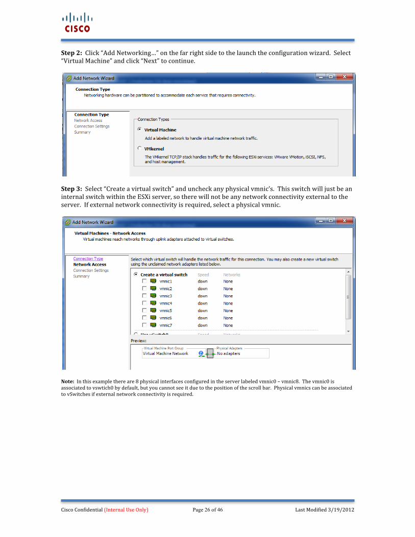
Step 2: Click “Add Networking…” on the far right side to the launch the configuration wizard. Select “Virtual Machine” and click “Next” to continue.
Step 3: Select “Create a virtual switch” and uncheck any physical vmnic’s. This switch will just be an internal switch within the ESXi server, so there will not be any network connectivity external to the server. If external network connectivity is required, select a physical vmnic.
Note: In this example there are 8 physical interfaces configured in the server labeled vmnic0 – vmnic8. The vmnic0 is associated to vswtich0 by default, but you cannot see it due to the position of the scroll bar. Physical vmnics can be associated to vSwitches if external network connectivity is required.
Cisco Confidential (Internal Use Only) Page 27 of 46 Last Modified 3/19/2012
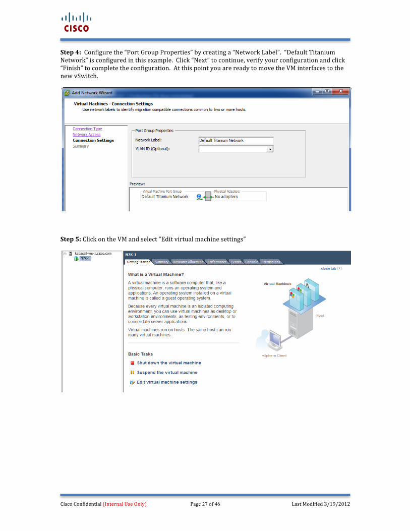
Step 4: Configure the “Port Group Properties” by creating a “Network Label”. “Default Titanium Network” is configured in this example. Click “Next” to continue, verify your configuration and click “Finish” to complete the configuration. At this point you are ready to move the VM interfaces to the new vSwitch.
Step 5: Click on the VM and select “Edit virtual machine settings”
Cisco Confidential (Internal Use Only) Page 28 of 46 Last Modified 3/19/2012
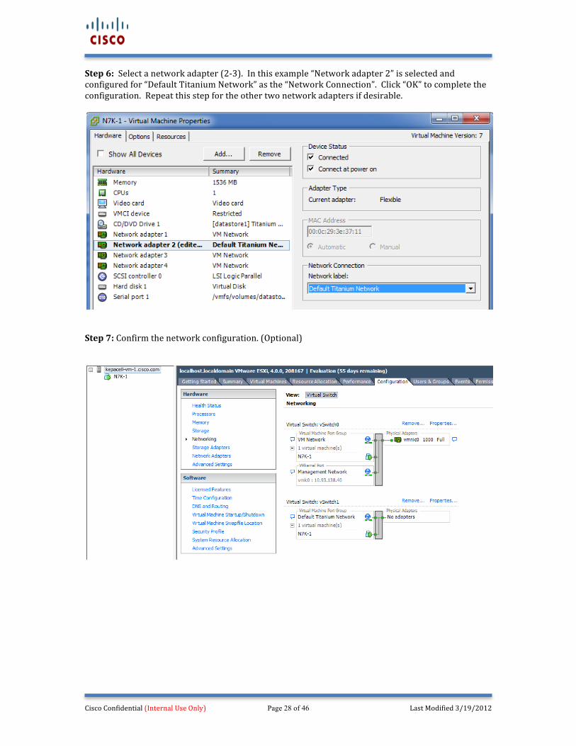
Step 6: Select a network adapter (2-‐3). In this example “Network adapter 2” is selected and configured for “Default Titanium Network” as the “Network Connection”. Click “OK” to complete the configuration. Repeat this step for the other two network adapters if desirable.
Step 7: Confirm the network configuration. (Optional)
Cisco Confidential (Internal Use Only) Page 29 of 46 Last Modified 3/19/2012
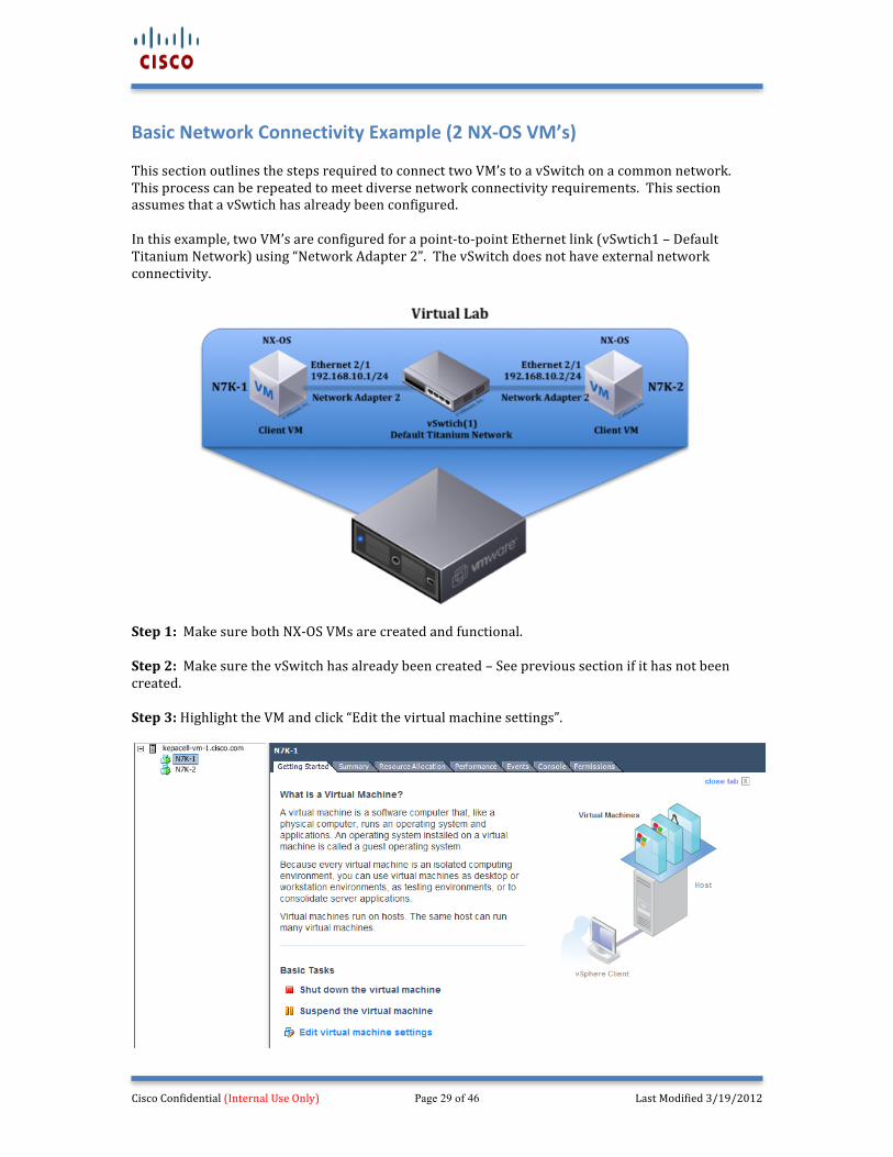
Basic Network Connectivity Example (2 NX-‐OS VM’s) This section outlines the steps required to connect two VM’s to a vSwitch on a common network. This process can be repeated to meet diverse network connectivity requirements. This section assumes that a vSwtich has already been configured. In this example, two VM’s are configured for a point-‐to-‐point Ethernet link (vSwtich1 – Default Titanium Network) using “Network Adapter 2”. The vSwitch does not have external network connectivity.
Step 1: Make sure both NX-‐OS VMs are created and functional. Step 2: Make sure the vSwitch has already been created – See previous section if it has not been created. Step 3: Highlight the VM and click “Edit the virtual machine settings”.
Cisco Confidential (Internal Use Only) Page 30 of 46 Last Modified 3/19/2012
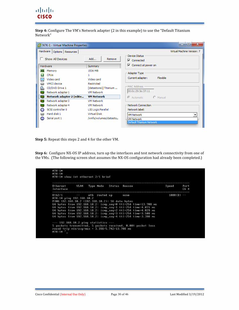
Step 4: Configure The VM’s Network adapter (2 in this example) to use the “Default Titanium Network”
Step 5: Repeat this steps 2 and 4 for the other VM. Step 6: Configure NX-‐OS IP address, turn up the interfaces and test network connectivity from one of the VMs. (The following screen shot assumes the NX-‐OS configuration had already been completed.)
Cisco Confidential (Internal Use Only) Page 31 of 46 Last Modified 3/19/2012
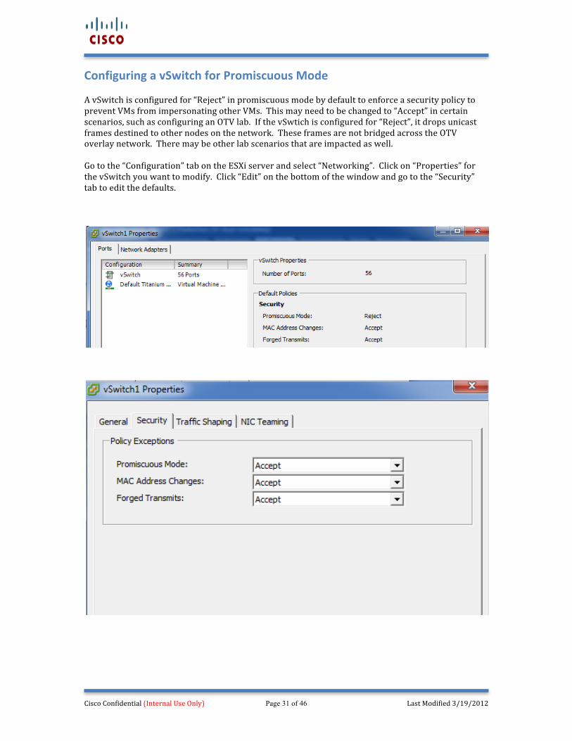
Configuring a vSwitch for Promiscuous Mode A vSwitch is configured for “Reject” in promiscuous mode by default to enforce a security policy to prevent VMs from impersonating other VMs. This may need to be changed to “Accept” in certain scenarios, such as configuring an OTV lab. If the vSwtich is configured for “Reject”, it drops unicast frames destined to other nodes on the network. These frames are not bridged across the OTV overlay network. There may be other lab scenarios that are impacted as well. Go to the “Configuration” tab on the ESXi server and select “Networking”. Click on “Properties” for the vSwitch you want to modify. Click “Edit” on the bottom of the window and go to the “Security” tab to edit the defaults.
Cisco Confidential (Internal Use Only) Page 32 of 46 Last Modified 3/19/2012
Summary The objective of this document is to provide the most simplistic installation process for running the NX-‐OS Titanium software in a virtual machine on a VMware ESXi 5.0.0, 4.1.0 or 4.0.0 server. As previously stated, the NX-‐OS Titanium software can run on many different VMware products. This includes laptops/workstations running VMware Player and Fusion, and different versions of ESX and ESXi for servers that have greater CPU and memory capabilities. The benefits are very similar when running NX-‐OS Titanium on a laptop/workstation or a server. However, the VMware ESXi server solution provides the ability to run more VM’s simultaneously and allows for more complex network configurations with the use of vSwitches. It should also be noted that the Nexus 1000v could be integrated into this procedure to allow for additional functionality. However, integrating the Nexus 1000v requires additional hardware (DRAM), software (VMware vCenter) and configuration steps that are not included in this document. The VMware ESXi solution outlined in this document should be useful for most testing and training lab environments.
Cisco Confidential (Internal Use Only) Page 33 of 46 Last Modified 3/19/2012
Appendices:
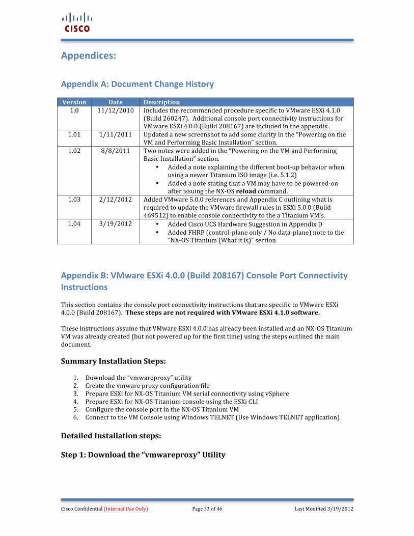
Appendix A: Document Change History Version Date Description 1.0 11/12/2010 Includes the recommended procedure specific to VMware ESXi 4.1.0
(Build 260247). Additional console port connectivity instructions for VMware ESXi 4.0.0 (Build 208167) are included in the appendix.
1.01 1/11/2011 Updated a new screenshot to add some clarity in the “Powering on the VM and Performing Basic Installation” section.
1.02 8/8/2011 Two notes were added in the “Powering on the VM and Performing Basic Installation” section.
• Added a note explaining the different boot-‐up behavior when using a newer Titanium ISO image (i.e. 5.1.2)
• Added a note stating that a VM may have to be powered-‐on after issuing the NX-‐OS reload command.
1.03 2/12/2012 Added VMware 5.0.0 references and Appendix C outlining what is required to update the VMware firewall rules in ESXi 5.0.0 (Build 469512) to enable console connectivity to the a Titanium VM’s.
1.04 3/19/2012 • Added Cisco UCS Hardware Suggestion in Appendix D • Added FHRP (control-‐plane only / No data-‐plane) note to the
“NX-‐OS Titanium (What it is)” section.
Appendix B: VMware ESXi 4.0.0 (Build 208167) Console Port Connectivity Instructions This section contains the console port connectivity instructions that are specific to VMware ESXi 4.0.0 (Build 208167). These steps are not required with VMware ESXi 4.1.0 software. These instructions assume that VMware ESXi 4.0.0 has already been installed and an NX-‐OS Titanium VM was already created (but not powered up for the first time) using the steps outlined the main document. Summary Installation Steps:
1. Download the “vmwareproxy” utility 2. Create the vmware proxy configuration file 3. Prepare ESXi for NX-‐OS Titanium VM serial connectivity using vSphere 4. Prepare ESXi for NX-‐OS Titanium console using the ESXi CLI 5. Configure the console port in the NX-‐OS Titanium VM 6. Connect to the VM Console using Windows TELNET (Use Windows TELNET application)
Detailed Installation steps: Step 1: Download the “vmwareproxy” Utility
Cisco Confidential (Internal Use Only) Page 34 of 46 Last Modified 3/19/2012
The VMware Proxy utility was created by Sachin Karisaddappa to enable serial console access required by the NX-‐OS Titanium software during the initial installation. This utility runs from the VMware ESXi server CLI as a daemon. This utility is typically only needed when a VM is created. Download the VMware proxy utility “vmwareproxy.bin” from the following site. You will upload this utility in the future to the VMware ESXi server datastore.
Download Link: http://bock-‐bock.cisco.com/wiki/N7K:Titanium:images Step 2: Create the VMware Proxy Configuration File The VMware Proxy configuration file is referenced by the VMware Proxy utility and specifies how VM’s serial devices (named pipes) match to the VMware ESXi TELNET ports. The contents of this file will be used during the VM installation procedure when creating the serial device. Create a file called “vmwareproxy.conf” with a text editor and save it to your laptop. You will upload this file in the future to the VMware ESXi server datastore. Syntax Example: When you create the serial device in the VM, you will reference the values highlighted in bold text. You will create a directory call “pipes” in the datastore, you will associate “com1” with the specified VM, and you will associate TELNET port 9001 to the VM and open the port on the ESXi server. The bold values can be different, but they must match between the VMware Proxy configuration file and the VM serial device configuration.
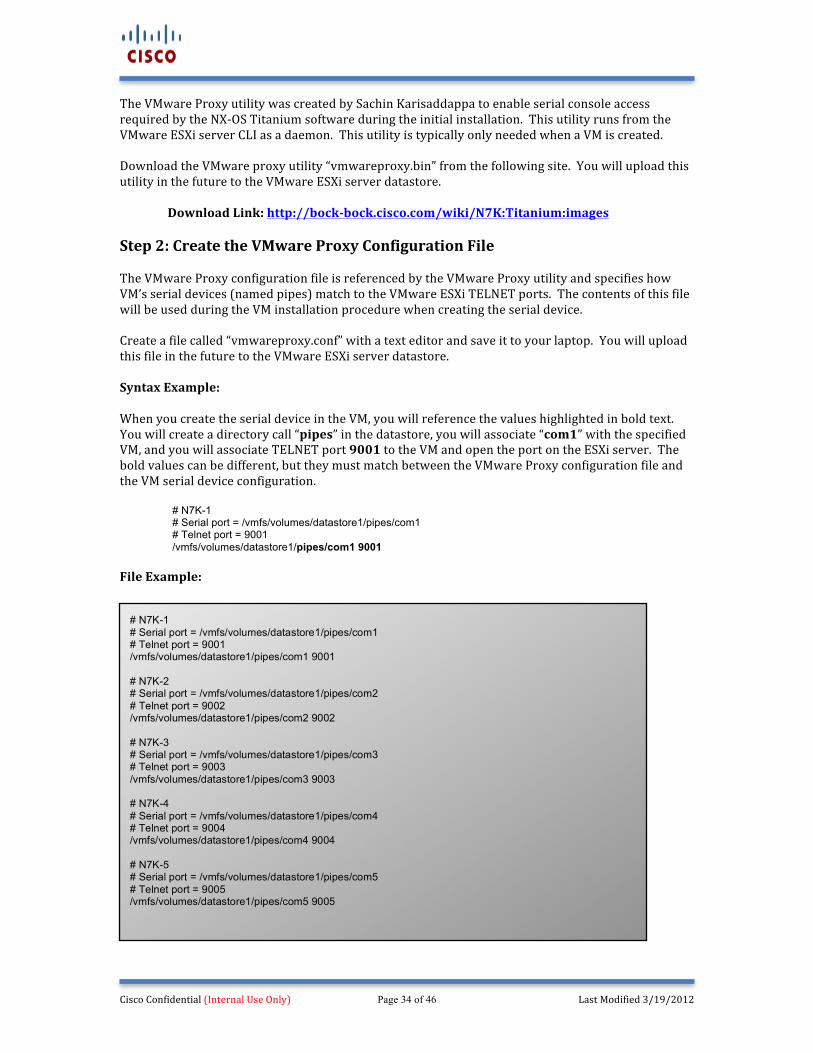
# N7K-1 # Serial port = /vmfs/volumes/datastore1/pipes/com1 # Telnet port = 9001 /vmfs/volumes/datastore1/pipes/com1 9001
File Example:
# N7K-1
# Serial port = /vmfs/volumes/datastore1/pipes/com1 # Telnet port = 9001 /vmfs/volumes/datastore1/pipes/com1 9001 # N7K-2 # Serial port = /vmfs/volumes/datastore1/pipes/com2 # Telnet port = 9002 /vmfs/volumes/datastore1/pipes/com2 9002 # N7K-3 # Serial port = /vmfs/volumes/datastore1/pipes/com3 # Telnet port = 9003 /vmfs/volumes/datastore1/pipes/com3 9003 # N7K-4 # Serial port = /vmfs/volumes/datastore1/pipes/com4 # Telnet port = 9004 /vmfs/volumes/datastore1/pipes/com4 9004 # N7K-5 # Serial port = /vmfs/volumes/datastore1/pipes/com5 # Telnet port = 9005 /vmfs/volumes/datastore1/pipes/com5 9005
Cisco Confidential (Internal Use Only) Page 35 of 46 Last Modified 3/19/2012
Note: Five serial connections were created in this example. Create more serial connections than you plan to use so you don’t have to go back and edit files and re-‐execute the VMware Proxy utility. Doing so will save you time in the future.
Cisco Confidential (Internal Use Only) Page 36 of 46 Last Modified 3/19/2012
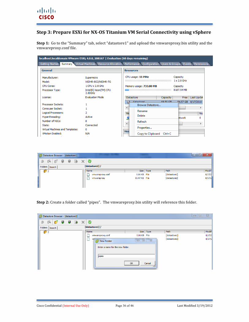
Step 3: Prepare ESXi for NX-‐OS Titanium VM Serial Connectivity using vSphere Step 1: Go to the “Summary” tab, select “datastore1” and upload the vmwareproxy.bin utility and the vmwareproxy.conf file.
Step 2: Create a folder called “pipes”. The vmwareproxy.bin utility will reference this folder.
Cisco Confidential (Internal Use Only) Page 37 of 46 Last Modified 3/19/2012
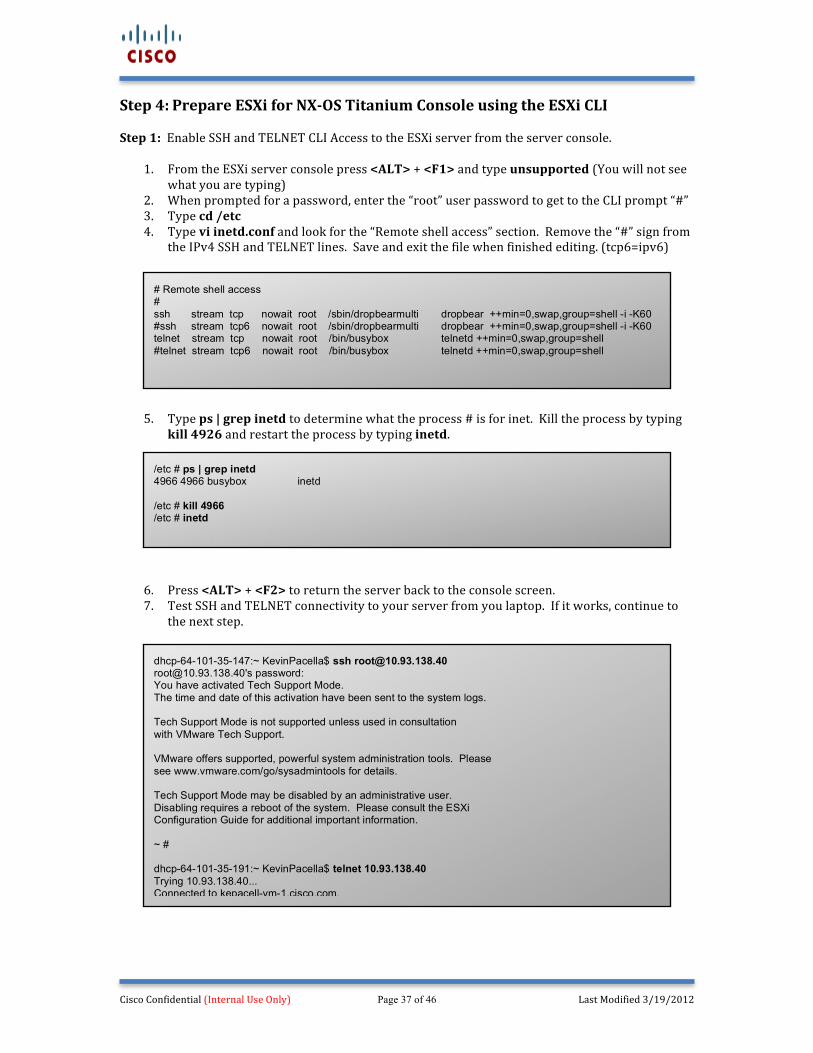
Step 4: Prepare ESXi for NX-‐OS Titanium Console using the ESXi CLI Step 1: Enable SSH and TELNET CLI Access to the ESXi server from the server console.
1. From the ESXi server console press <ALT> + <F1> and type unsupported (You will not see what you are typing)
2. When prompted for a password, enter the “root” user password to get to the CLI prompt “#” 3. Type cd /etc 4. Type vi inetd.conf and look for the “Remote shell access” section. Remove the “#” sign from
the IPv4 SSH and TELNET lines. Save and exit the file when finished editing. (tcp6=ipv6)
5. Type ps | grep inetd to determine what the process # is for inet. Kill the process by typing
kill 4926 and restart the process by typing inetd.
6. Press <ALT> + <F2> to return the server back to the console screen. 7. Test SSH and TELNET connectivity to your server from you laptop. If it works, continue to
the next step.
# Remote shell access # ssh stream tcp nowait root /sbin/dropbearmulti dropbear ++min=0,swap,group=shell -i -K60 #ssh stream tcp6 nowait root /sbin/dropbearmulti dropbear ++min=0,swap,group=shell -i -K60 telnet stream tcp nowait root /bin/busybox telnetd ++min=0,swap,group=shell #telnet stream tcp6 nowait root /bin/busybox telnetd ++min=0,swap,group=shell
/etc # ps | grep inetd 4966 4966 busybox inetd /etc # kill 4966 /etc # inetd
dhcp-64-101-35-147:~ KevinPacella$ ssh [email protected] [email protected]'s password: You have activated Tech Support Mode. The time and date of this activation have been sent to the system logs. Tech Support Mode is not supported unless used in consultation with VMware Tech Support. VMware offers supported, powerful system administration tools. Please see www.vmware.com/go/sysadmintools for details. Tech Support Mode may be disabled by an administrative user. Disabling requires a reboot of the system. Please consult the ESXi Configuration Guide for additional important information. ~ # dhcp-64-101-35-191:~ KevinPacella$ telnet 10.93.138.40 Trying 10.93.138.40... Connected to kepacell-vm-1.cisco.com. Escape character is '^]'.
Cisco Confidential (Internal Use Only) Page 38 of 46 Last Modified 3/19/2012
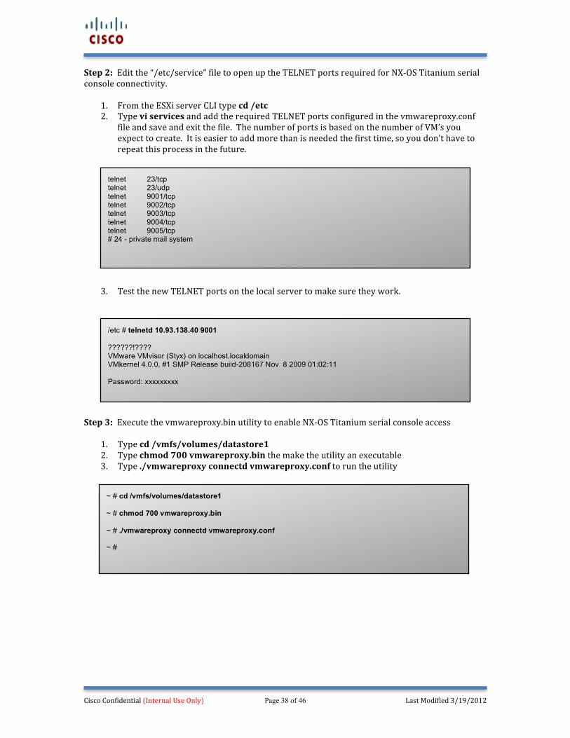
Step 2: Edit the “/etc/service” file to open up the TELNET ports required for NX-‐OS Titanium serial console connectivity.
1. From the ESXi server CLI type cd /etc 2. Type vi services and add the required TELNET ports configured in the vmwareproxy.conf
file and save and exit the file. The number of ports is based on the number of VM’s you expect to create. It is easier to add more than is needed the first time, so you don’t have to repeat this process in the future.
3. Test the new TELNET ports on the local server to make sure they work.
Step 3: Execute the vmwareproxy.bin utility to enable NX-‐OS Titanium serial console access
1. Type cd /vmfs/volumes/datastore1 2. Type chmod 700 vmwareproxy.bin the make the utility an executable 3. Type ./vmwareproxy connectd vmwareproxy.conf to run the utility
/etc # telnetd 10.93.138.40 9001 ??????!???? VMware VMvisor (Styx) on localhost.localdomain VMkernel 4.0.0, #1 SMP Release build-208167 Nov 8 2009 01:02:11 Password: xxxxxxxxx
telnet 23/tcp telnet 23/udp telnet 9001/tcp telnet 9002/tcp telnet 9003/tcp telnet 9004/tcp telnet 9005/tcp # 24 - private mail system
~ # cd /vmfs/volumes/datastore1 ~ # chmod 700 vmwareproxy.bin ~ # ./vmwareproxy connectd vmwareproxy.conf ~ #
Cisco Confidential (Internal Use Only) Page 39 of 46 Last Modified 3/19/2012
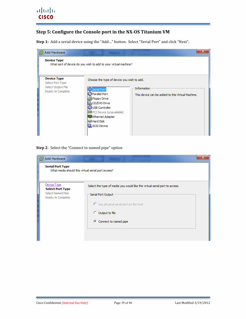
Step 5: Configure the Console port in the NX-‐OS Titanium VM Step 1: Add a serial device using the “Add…” button. Select “Serial Port” and click “Next”.
Step 2: Select the “Connect to named pipe” option
Cisco Confidential (Internal Use Only) Page 40 of 46 Last Modified 3/19/2012
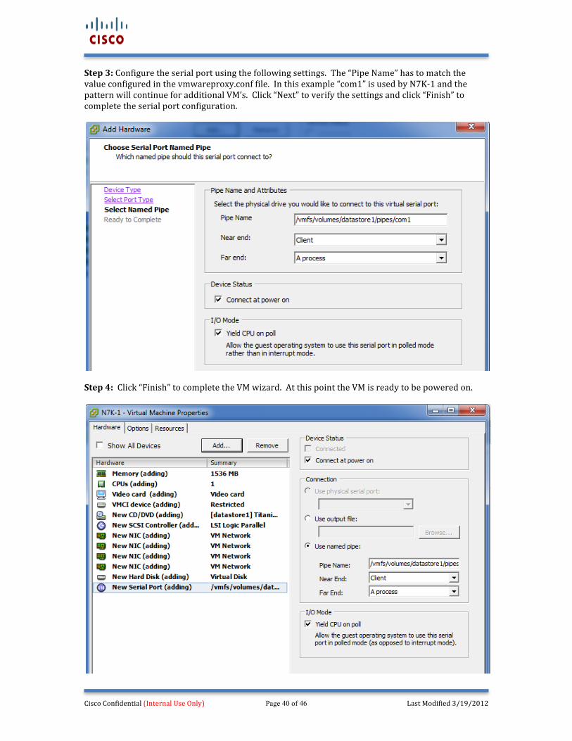
Step 3: Configure the serial port using the following settings. The “Pipe Name” has to match the value configured in the vmwareproxy.conf file. In this example “com1” is used by N7K-‐1 and the pattern will continue for additional VM’s. Click “Next” to verify the settings and click “Finish” to complete the serial port configuration.
Step 4: Click “Finish” to complete the VM wizard. At this point the VM is ready to be powered on.
Cisco Confidential (Internal Use Only) Page 41 of 46 Last Modified 3/19/2012
Step 6: Connecting to the VM Console using Windows TELNET This step occurs after the VM has been powered up and the system NX-‐OS images had been loaded. Connect to the VM console using TELNET. Using a Windows operating system, open a CMD window and open a TELNET session (TELNET is disabled in Windows 7 by default. You have to enable it under the software section within the Control Panel.) Type Telnet to get to the “Microsoft Telnet>” prompt, once at the prompt type u crlf to disable double carriage returns. Type; open x.x.x.x 9001 to connect to the NX-‐OS VM console. Depending on how fast you do this, you may see the VM boot up. If it takes longer you but will eventually see a prompt for the “admin” password.
Follow the remainder of the instructions previously outlined in the main document to finish the NX-‐OS Titanium VM installation.
Cisco Confidential (Internal Use Only) Page 42 of 46 Last Modified 3/19/2012
Appendix C: VMware ESXi 5.0.0 (Build 469512) Console Port Connectivity Instructions VMware ESXi 5.0.0 introduced a new firewall that requires additional ports to be opened to permit inbound sessions when connecting via TELNET to a NX-‐OS Titanium console port. The instructions for installing the VMware ESXi server and creating the VM’s are essentially the same as version 4.1.0 and 4.0.0, so only the firewall instructions are listed below to allow for NX-‐OS Titanium console access. Summary Installation Steps:
1. Create a new XML file that permits the inbound TCP sessions (ports) that will used for TELNET (i.e. TCP 9001-‐9010) – These ports should match the ports configured under the serial port section when creating the NX-‐OS Titanium VM(s).
2. Upload the file to the VMware datastore using the vSphere client. 3. Edit the /etc/rc.local file to ensure the new XML file updates the firewall rule set when the
VMware ESXi server is reloaded. (This required SSH connectivity to the VMware ESXi server.
4. Reload the ESXi server using the vSPhere client to load the new rules and ensure steps 1-‐3 were performed properly.
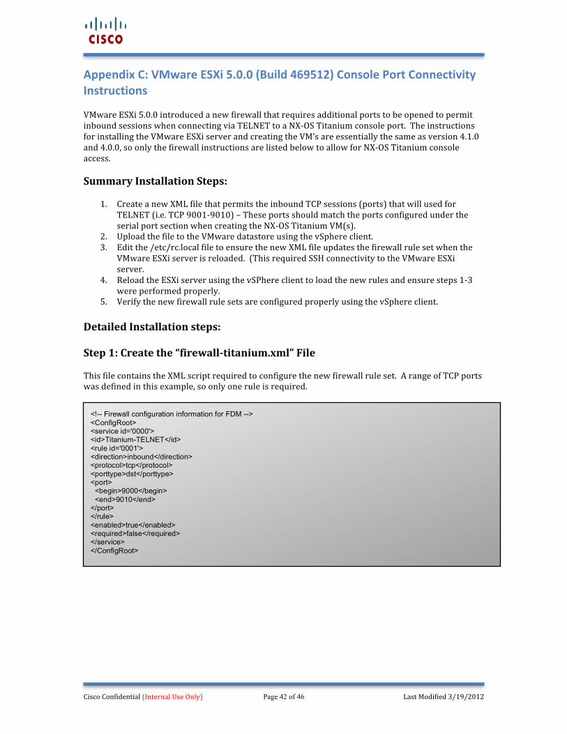
5. Verify the new firewall rule sets are configured properly using the vSphere client. Detailed Installation steps: Step 1: Create the “firewall-‐titanium.xml” File This file contains the XML script required to configure the new firewall rule set. A range of TCP ports was defined in this example, so only one rule is required.
<!-- Firewall configuration information for FDM --> <ConfigRoot> <service id='0000'> <id>Titanium-TELNET</id> <rule id='0001'> <direction>inbound</direction> <protocol>tcp</protocol> <porttype>dst</porttype> <port> <begin>9000</begin> <end>9010</end> </port> </rule> <enabled>true</enabled> <required>false</required> </service> </ConfigRoot>
Cisco Confidential (Internal Use Only) Page 43 of 46 Last Modified 3/19/2012
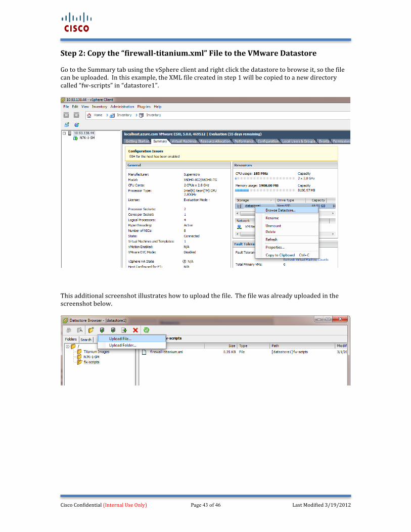
Step 2: Copy the “firewall-‐titanium.xml” File to the VMware Datastore Go to the Summary tab using the vSphere client and right click the datastore to browse it, so the file can be uploaded. In this example, the XML file created in step 1 will be copied to a new directory called “fw-‐scripts” in “datastore1”.
This additional screenshot illustrates how to upload the file. The file was already uploaded in the screenshot below.
Cisco Confidential (Internal Use Only) Page 44 of 46 Last Modified 3/19/2012
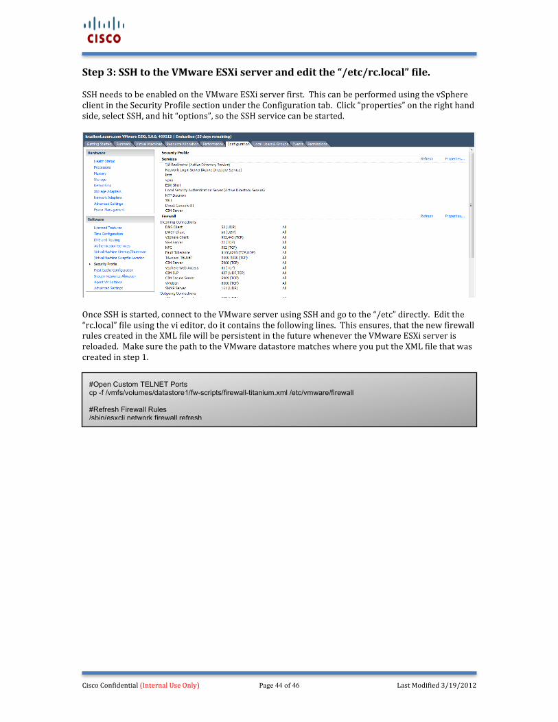
Step 3: SSH to the VMware ESXi server and edit the “/etc/rc.local” file. SSH needs to be enabled on the VMware ESXi server first. This can be performed using the vSphere client in the Security Profile section under the Configuration tab. Click “properties” on the right hand side, select SSH, and hit “options”, so the SSH service can be started.
Once SSH is started, connect to the VMware server using SSH and go to the “/etc” directly. Edit the “rc.local” file using the vi editor, do it contains the following lines. This ensures, that the new firewall rules created in the XML file will be persistent in the future whenever the VMware ESXi server is reloaded. Make sure the path to the VMware datastore matches where you put the XML file that was created in step 1.
#Open Custom TELNET Ports cp -f /vmfs/volumes/datastore1/fw-scripts/firewall-titanium.xml /etc/vmware/firewall #Refresh Firewall Rules /sbin/esxcli network firewall refresh
Cisco Confidential (Internal Use Only) Page 45 of 46 Last Modified 3/19/2012
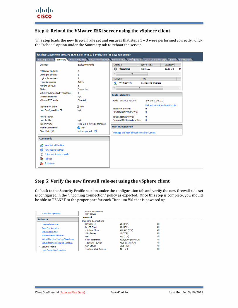
Step 4: Reload the VMware ESXi server using the vSphere client This step loads the new firewall rule set and ensures that steps 1 – 3 were performed correctly. Click the “reboot” option under the Summary tab to reboot the server.
Step 5: Verify the new firewall rule-‐set using the vSphere client Go back to the Security Profile section under the configuration tab and verify the new firewall rule set is configured in the “Incoming Connection” policy as expected. Once this step is complete, you should be able to TELNET to the proper port for each Titanium VM that is powered up.
Cisco Confidential (Internal Use Only) Page 46 of 46 Last Modified 3/19/2012
Appendix D: Cisco UCS Hardware for VMware/NX-‐OS Titanium SuperMicro servers where originally recommended for NX-‐OS Titanium due to their performance and cost. However, with the release of the Cisco Unified Compute (UCS) product line and the ability to virtualize the server with a greater number of virtual machines, it makes more sense to buy a more powerful UCS server instead. Different server models can be deployed depending on the performance requirements. However, the Cisco UCS 200 M2 series is a cost effective, 1 RU, high-‐performance server that works really well. The following server specifications worked great during testing, but different components (CPU, MEM, DISK) can be selected based on the requirements. Accessory components, such as blanks, heat syncs, etc… are not documented. Cisco UCS 200 M2 (1 Rack Unit) Quantity UCS 200 M2 Chassis 1x Intel Xeon E5649 2.53 GHz (6 Core) 2x (12 Cores) 16GB DDR3-‐1066MHx-‐RDIMM 6x (96 MB) PCI card-‐16 1x LSI 1064 RAID 0, 1, 1e 1x (Works with VMware) 2TB SAS 7.2K RPM 3.5in 4x (8 TB) 650w Power Supply (AC) 2x (You only really need 1) G3 Shorter Stronger Rail Kit 1x