Embed Size (px)
DESCRIPTION
Description of dams in New Zealand with details and relevant data
Citation preview


Dams
in
New Zealand
August 1989

Cover Photo: Rangipo Spillway

Dams in New Zealand
Preface
The 40 year period from the construction of the Maretai Dam to the substantial completion of the ClydeDam in 1989 has been one of extraordinary dam building activity in New Zealand. Most dams have beenbuilt for hydro electric or public water supply purposes and some have multiple uses. All have beendesigned and built with great care and state of the art skills. Now as the 1980's decade draws to a close itseems that the last decade of the century will see few new dams and that dam engineers may be moreconcerned with safety surveillance, cost effective maintenance and optimum operation.
It is thus appropriate that NZSOLD should publish this book to place on record in a convenient referenceform, information and illustrations relating to some of the more notable dams that have been built sincedam construction commenced in New Zealand near the start of the 20th century. This book is theSociety's tribute to the owners, designers and constructors of those major civil engineering structures - thedams, which contribute so much to the standard of living enjoyed by New Zealand.
The Society records its gratitude to its Publications Committee, its Technical Secretary, and the variousdam owners who have provided the high quality colour photographs and other source material at no costto the Society thereby making this book possible.
I R PairmanChairman
It will be noted that for dams now in the ownership of the Electricity Corporation of New Zealand Ltd,designers and constructors are varyingly shown as Public Works Department, Ministry of Works, Ministryof Works and Development, State Hydro-electric Department, NZ Electricity Department and ElectricityDivision of Ministry of Energy. This is due to changes in organisation and name that have taken placeover the years, however the essential core knowledge and expertise remains with their present daycounterparts - principally Works Consultancy Division of Works and Development Services Corporationand PowerDesignBuild Group Ltd, a subsidiary of the Electricity Corporation of New Zealand Ltd.
No doubt similar changes will have occurred within local government and private consultants.

Dams in New ZealandThe publication of this book by the New Zealand Society on Large Dams is a significant event. Here, forthe first time, descriptions and photographs are brought together in one volume. It indicates that theSociety's committee is proud of the achievements of New Zealand's civil engineers in constructing andmaintaining these facilities.
Dams are often tucked away in seldom-visited parts of the countryside. Very few become recognizedtourist attractions. The excellent colour photographs presented here, which in many cases are the result ofspecially commissioned aerial camera work, will enable the beauty of many more to be appreciated by thearm-chair traveller. At the same time, this book demonstrates the capabilities of New Zealand designers,constructors and operators in this field. With its earthquake hazard and its geologically recent soils, thiscountry presents special challenges in the design and construction of dams. These problems have beensuccessfully overcome, but not without occasional set-backs, sometimes major.
Dams are an essential part of our civilization. The earliest dam in recorded history was at Kosheish, inEgypt, where a masonry structure is reported to have been constructed about 2900 BC, across the Nile tosupply water to King Menes' capital at Memphis, though nothing of it now remains. Even by today'sstandards, with a height of 15 m, it was a sizeable structure. This shows that dam-building was awell-established art even at the dawn of recorded history.
Water supplies to cities and irrigation of land were the earliest purposes for which dams were built. Lifein cities as we know it is totally dependent on adequate supplies of water. A safe water supply andadequate sewerage are the prime essentials for public health, though seldom does the average citizenpause to consider this obvious fact. Most, though not all, of this water comes from impounding dams.Now, the generation of hydro-electric power is one of the main benefits derived.
Dams confer benefits beyond the immediate one of storing needed water. Less obviously, by virtue of itsstorage capability, a dam reduces downstream peak flows in floods. Occasionally, the lake created canbecome a scenic attraction. A view of snow- capped Mount Egmont (Taranaki) reflected in the tranquilwaters of Lake Mangamahoe has appeared in many calendars. Of the tourists, local and overseas, whovisit this beauty-spot, few, I suspect, realize that it is a man-made lake or that it produces hydro electricpower for New Plymouth and has been doing so for over half a century. New Zealand's success in recentyears in the sport of rowing has been greatly assisted by having on Lake Karapiro a course of internationalchampionship standard.
The environmental impact of a dam can also be detrimental, of course. Of recent years dams have beengetting a tad press'. Popular articles emphasizing the negative effects of the High Aswan dam on theNile, for example, have received wide circulation while completely ignoring the benefits. A balancedappraisal would be more helpful. Recognition of the importance of environmental effects and carefultreatment of the development to take account of these effects is now an essential part of dam design. Aslong as people of the community continue to demand a high material standard of living, with reliableutilities, further development of natural resources in this way is inevitable.
The most spectacular type of dam is undoubtedly the concrete arch. This type can only be built at siteswhere both the foundation beneath the dam and the valley walls supporting its abutments are of soundrock. Such conditions, common in the Swiss Alps, are more rarely encountered in this country. Maraetai(height 87 m) is the highest dam of this type in New Zealand. Other types of concrete structure,including gravity dams (which rely for stability on their mass), buttress and multiple arch dams, alsorequire solid foundations, but their demands on the valley walls are less severe.
Least demanding of all are earth- and rock-fill dams which may be sufficiently flexible to accommodatefoundation deformation. There are some who would claim that these are the least spectacular inappearance. An earth-fill dam can, and indeed some do, look like just another hillside! No-one coulddeny, however, that Benmore, our highest dam, is a spectacular sight. Of the dams constructed in thelatter half of this century, the vast majority are of earth-fill construction. There are two main reasons forthis. One is that earthmoving has steadily become less expensive by comparison with concreteconstruction; the other, of course, is that most of the dam sites which could provide solid foundationshave already been used!
This book will, I feel sure, prove interesting and enjoyable to all those who peruse it, as well as being avaluable work of reference.
Peter W Taylor
Emeritus Professor, University of Auckland.
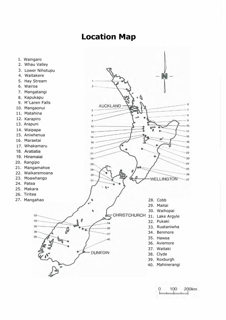
1. Waingaro2. Whau Valley
3. Lower Nihotupu4. Waitakere5. Hay Stream6. Wairoa
7. Mangatangi8. Kapukapu9. M cLaren Falls
10. Mangaonui11. Matahina12. Karapiro13. Arapuni
14. Waipapa15. Aniwhenua16. Maraetai
17. Whakamaru18. Aratiatia19. Hinemaiai20. Rangipo21. Mangamahoe22. Waikaremoana23. Moawhango24. Patea25. Makara26. Tiritea27. Mangahao 28. Cobb
29. Maitai30. Waihopai31. Lake Argyle32. Pukaki
33. Ruataniwha34. Benmore35. Hawea36. Aviemore
37. Waitaki38. Clyde39. Roxburgh40. Mahinerangi
Location Map
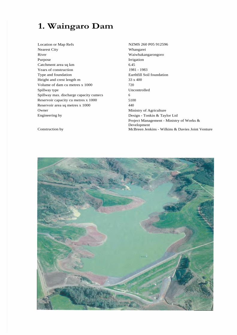
1. Waingaro Dam
Location or Map Refs NZMS 260 P05 912596
Nearest City Whangarei
River Waiwhakangarongoro
Purpose Irrigation
Catchment area sq km 6.45
Years of construction 1981 - 1983
Type and foundation Earthfill Soil foundationHeight and crest length m 33 x 400
Volume of dam cu metres x 1000 720
Spillway type UncontrolledSpillway max. discharge capacity cumecs 6
Reservoir capacity cu metres x 1000 5100
Reservoir area sq metres x 1000 440
Owner Ministry of AgricultureEngineering by Design - Tonkin & Taylor Ltd
Project Management - Ministry of Works &Development
Construction by McBreen Jenkins - Wilkins & Davies Joint Venture
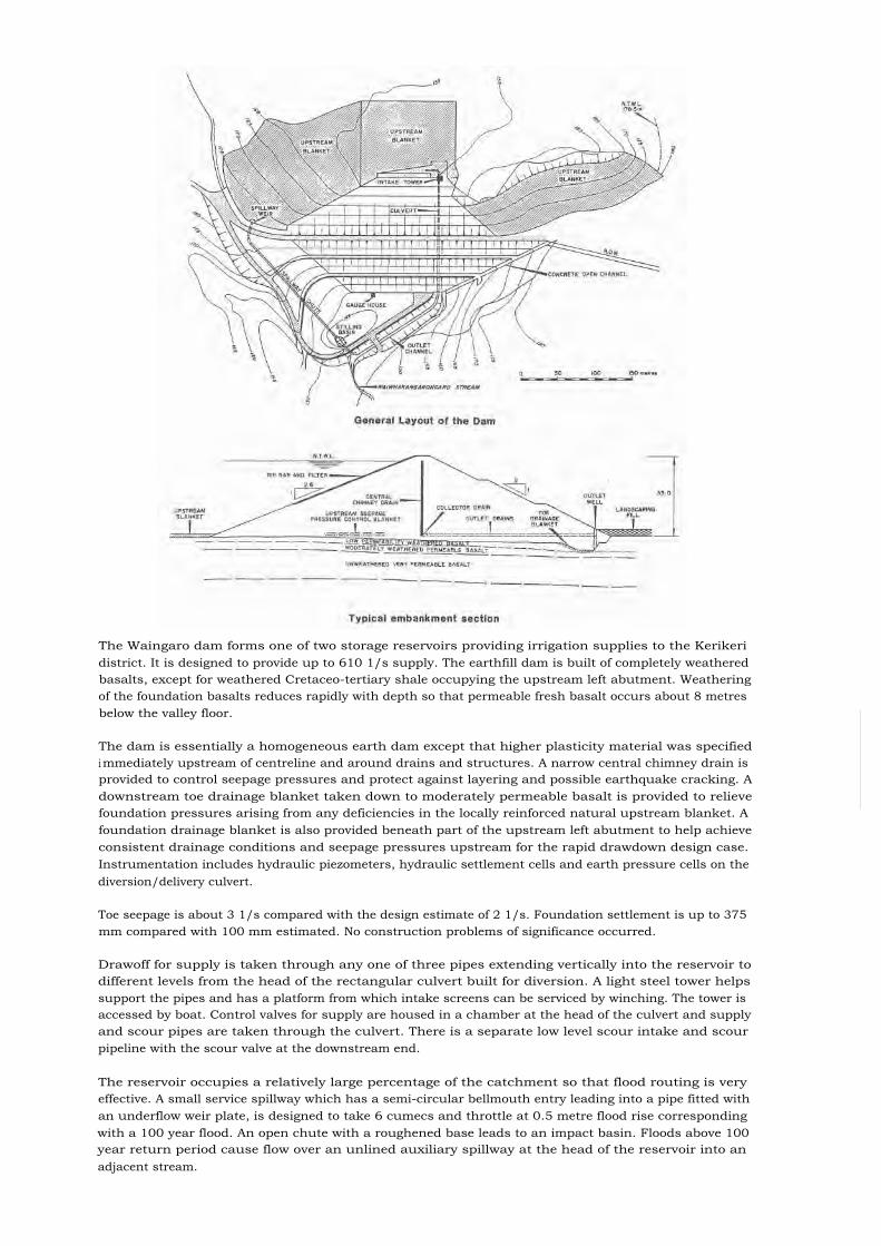
The Waingaro dam forms one of two storage reservoirs providing irrigation supplies to the Kerikeridistrict. It is designed to provide up to 610 1/s supply. The earthfill dam is built of completely weatheredbasalts, except for weathered Cretaceo-tertiary shale occupying the upstream left abutment. Weatheringof the foundation basalts reduces rapidly with depth so that permeable fresh basalt occurs about 8 metresbelow the valley floor.
The dam is essentially a homogeneous earth dam except that higher plasticity material was specifiedi mmediately upstream of centreline and around drains and structures. A narrow central chimney drain isprovided to control seepage pressures and protect against layering and possible earthquake cracking. Adownstream toe drainage blanket taken down to moderately permeable basalt is provided to relievefoundation pressures arising from any deficiencies in the locally reinforced natural upstream blanket. Afoundation drainage blanket is also provided beneath part of the upstream left abutment to help achieveconsistent drainage conditions and seepage pressures upstream for the rapid drawdown design case.Instrumentation includes hydraulic piezometers, hydraulic settlement cells and earth pressure cells on thediversion/delivery culvert.
Toe seepage is about 3 1/s compared with the design estimate of 2 1/s. Foundation settlement is up to 375mm compared with 100 mm estimated. No construction problems of significance occurred.
Drawoff for supply is taken through any one of three pipes extending vertically into the reservoir todifferent levels from the head of the rectangular culvert built for diversion. A light steel tower helpssupport the pipes and has a platform from which intake screens can be serviced by winching. The tower isaccessed by boat. Control valves for supply are housed in a chamber at the head of the culvert and supplyand scour pipes are taken through the culvert. There is a separate low level scour intake and scourpipeline with the scour valve at the downstream end.
The reservoir occupies a relatively large percentage of the catchment so that flood routing is veryeffective. A small service spillway which has a semi-circular bellmouth entry leading into a pipe fitted withan underflow weir plate, is designed to take 6 cumecs and throttle at 0.5 metre flood rise correspondingwith a 100 year flood. An open chute with a roughened base leads to an impact basin. Floods above 100year return period cause flow over an unlined auxiliary spillway at the head of the reservoir into anadjacent stream.
2. Whau Valley Dam
Location or Map Refs NZMS 1 N20 800986Nearest City WhangareiRiver WaiarohiaPurpose Water SupplyCatchment area sq km 7.36Years of construction July 1966 - May 1969Type and foundation Earth type, Soil foundationHeight and crest length m 26 x 230Volume of dam cu metres x 1000 425Spillway type UncontrolledSpillway max. discharge capacity cumecs 170 ( + 25 emergency spillway)Reservoir capacity cu metres x 1000 2045Reservoir area sq metres x 1000 220Owner Whangarei City CouncilEngineering by Tonkin and Taylor LimitedConstruction by Green and McCahill Limited
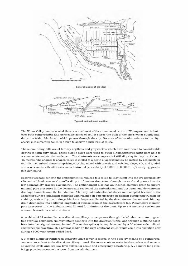
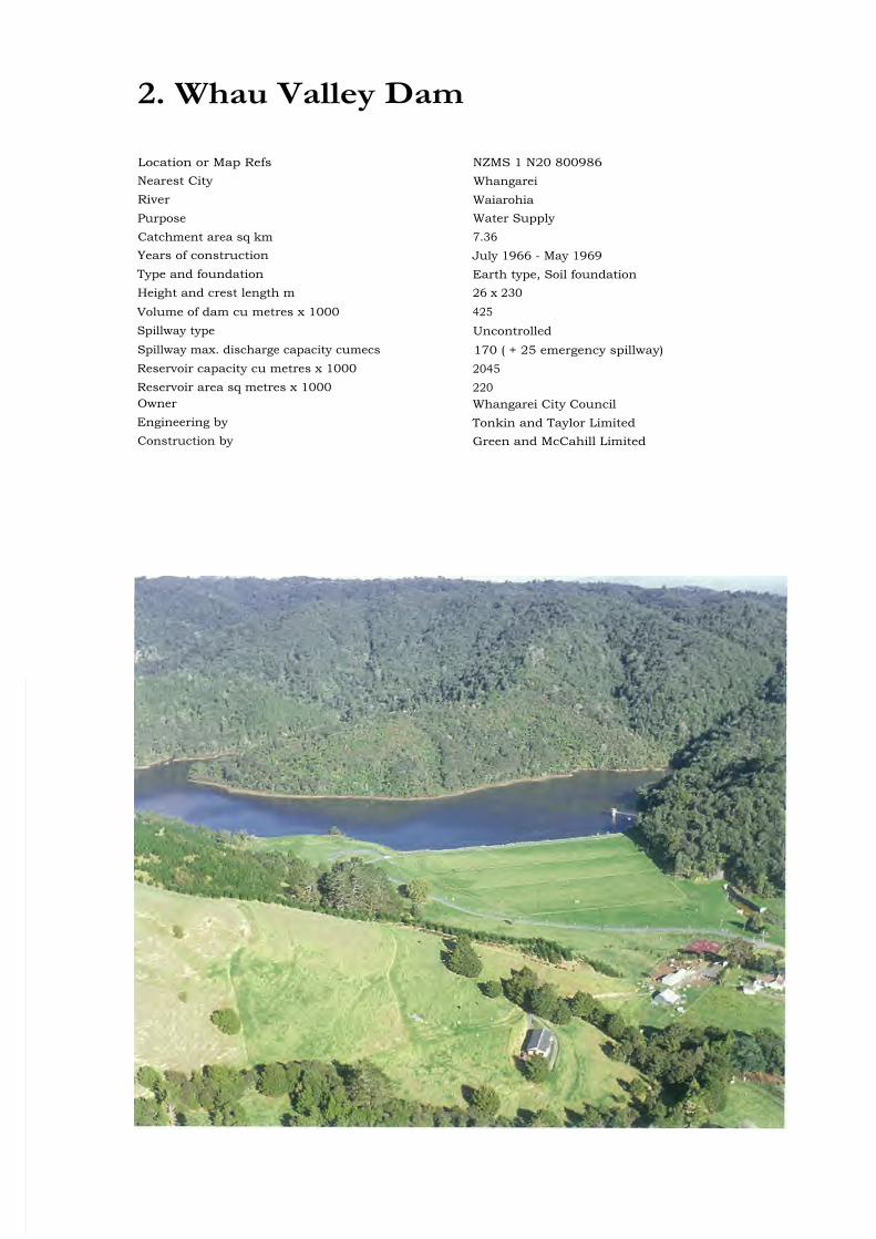
The Whau Valley dam is located three km northwest of the commercial centre of Whangarei and is builtover both compressible and permeable zones of soil. It stores the bulk of the city's water supply anddams the Waiarohia Stream which passes through the city. Because of its location relative to the city,special measures were taken in design to achieve a high level of safety.
The surrounding hills are of tertiary argillites and greywackes which have weathered to considerabledepths to form silty clays. These plastic clays were used to build a homogeneous earth dam able toaccommodate substantial settlement. The abutments are composed of stiff silty clay for depths of about15 metres. The original U-shaped valley is infilled to a depth of approximately 55 metres by sediments infour distinct subsoil zones comprising silty clay mixed with gravels and cobbles, clayey silt, and gradedscoracious sands with silt lenses and a horizontal permeability of 0.0001 to 0.00001 m/s overlying gravelsin a clay matrix.
Reservoir seepage beneath the embankment is reduced to a rolled fill clay cutoff into the low permeabilitysilts and a "plastic concrete" cutoff wall up to 15 metres deep taken through the sand and gravels into thelow permeability gravelly clay matrix. The embankment also has an inclined chimney drain to ensureminimal pore pressures in the downstream section of the embankment and upstream and downstreamdrainage blankets over the foundation. Relatively flat embankment slopes were adopted because of theweak near surface foundation materials with reliance on pore pressure dissipation during construction forstability, assisted by the drainage blankets. Seepage collected by the downstream blanket and chimneydrain discharges into a filtered longitudinal subsoil drain at the downstream toe. Piezometers monitorpore pressures in the embankment fill and foundation of the dam. Up to 1.4 metre of settlementoccurred beneath the central sections.
A combined 4.27 metre diameter diversion-spillway tunnel passes through the left abutment. An ungatedfree overflow bellmouth spillway intake connects into the diversion tunnel and through a stilling basinback into the original stream channel. The service spillway is supplemented by a 30 metre wide unlinedemergency spillway through a natural saddle on the right abutment which would come into operation onlyduring a 5000 year return period flood.
A 3 metre diameter reinforced concrete valve tower is joined at the base by means of a reinforcedconcrete box culvert to the diversion-spillway tunnel. The tower contains water intakes, valves and screensat varying levels and two low level valves for scour and emergency dewatering. A 75 metre long steelbridge provides access to the tower from the left abutment.

3. Lower Nihotupu Dam
Location or Map Refs NZMS 260 R11 541 698Nearest City AucklandRiver Nihotupu StreamPurpose Water Supply
Catchment area sq km 13Years of construction 1945 - 1948Type and foundation Earth, Waitemata series (miocene) sandstonesHeight and crest length m 24.7 x 381Volume of dam cu metres x 1000 359Spillway type Double-sided trough type - uncontrolledSpillway max. discharge capacity cumecs 480Reservoir capacity cu metres x 1000 4805Reservoir area sq metres x 1000 715Owner Auckland Regional AuthorityEngineering by Auckland City CouncilConstruction by Downer & Co.

The Lower Nihotupu dam is located alongside the Huia Road at the mouth of Nihotupu Stream. Theembankment is founded on Waitemata series (Miocene) sandstones and mudstones which underlie theWaitakere andesitic conglomerates.
The embankment is keyed into the country rock by means of a low concrete cut-off wall and by a groutcurtain on centre line. The bank itself comprises a clay-silt core section flanked by increasingly coarseningfill to silty gravels at both faces. The upstream face is finished to a slope of 1 in 3 and is faced with handpacked basalt stonework. The downstream face is sloped 2.5 to 1, bermed and grassed.
Waitemata strata weather readily to a very cohesive residual clay. This material dominated the vicinity ofthe dam and was in surplus supply. Silts and gravels however, were confined to flood plain terracedeposits in the valley floor and were in limited supply. Core design in particular therefore called fordevelopment of clay mixes stabilised with closely husbanded silts and grits.
At the time of its construction the darn created considerable interest as the first controlled rolled-fillstructure in the Dominion. The fill materials available and the vagaries of Auckland weather called forvery close supervision of material selection, moisture control, and compaction techniques, and to this enda fully equipped soil mechanics laboratory was established and used continuously. Construction problemslargely revolved around techniques for working, mixing and drying this cohesive fill to optimum moisturecontent appropriate to compaction with tractor-drawn equipment and sheep-foot rollers. Auckland'swell-spread rainfall gives rise to short working seasons for this type of work, and called for veryconcentrated effort whenever favourable weather eventuated. The bank was completed in 180 workingdays spread over three seasons at an average placing rate of 2,000 cu. metres per placing day.
The spillway at Lower Nihotupu is a double-sided trough type of 480 cumecs capacity located in theeastern abutment. The valve tower adjoins the spillway and seals the original 3.35 metre diameterdiversion tunnel.

4. Waitakere Dam
Location or Map Refs NZMS 260 Q11 466 769Nearest City AucklandRiver WaitakerePurpose Water SupplyCatchment area sq km 8.2Years of construction 1907 - 1910. Raised 4.9 metres 1926 - 1927Type and foundation Mass concreteHeight and crest length m 25.3 x 175Volume of dam cu metres x 1000 25.2Spillway type Broad crested weirReservoir capacity cu metres x 1000 1,850Reservoir area sq metres x 1000 278Owner Auckland Regional AuthorityEngineering by Auckland City CouncilConstruction by Auckland City Council
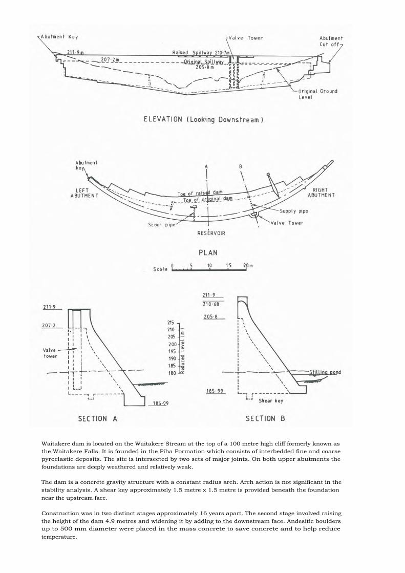
Waitakere dam is located on the Waitakere Stream at the top of a 100 metre high cliff formerly known asthe Waitakere Falls. It is founded in the Piha Formation which consists of interbedded fine and coarsepyroclastic deposits. The site is intersected by two sets of major joints. On both upper abutments thefoundations are deeply weathered and relatively weak.
The dam is a concrete gravity structure with a constant radius arch. Arch action is not significant in thestability analysis. A shear key approximately 1.5 metre x 1.5 metre is provided beneath the foundationnear the upstream face.
Construction was in two distinct stages approximately 16 years apart. The second stage involved raisingthe height of the dam 4.9 metres and widening it by adding to the downstream face. Andesitic bouldersup to 500 mm diameter were placed in the mass concrete to save concrete and to help reducetemperature.

5. Hays Stream Earth Dam
Location or Map Refs NZMS 260 R12 896 567
Nearest City Papakura
River Hays StreamPurpose Water SupplyCatchment area sq km 6.4Years of construction 1966 -1967Type and foundation Earth/rockfill gravity dam on rock/soil foundations
Height and crest length m 25.9 x 71
Volume of dam cu metres x 1000 57Spillway type UncontrolledSpillway max. discharge capacity cumecs 100Reservoir capacity cu metres x 1000 1230Reservoir area sq metres x 1000 141Owner Papakura City CouncilEngineering by Mandeno Chitty and BellConstruction by NZ Roadmakers Ltd

Papakura City Council has been responsible for supplying potable water to its residents since 1922 inwhich year a small concrete dam was constructed in the headwaters of Hays Stream, approximately 4 kmfrom the city boundary. This low-level intake structure provided negligible storage and becameincreasingly inadequate over the succeeding 40 years. The Hays Stream water supply source wassufficiently nearby and plentiful to prompt a decision in 1961 towards constructing a new storage damrather than joining the Auckland City Council (later Auckland Regional Authority) water supply scheme.
Early proposals for 7.6 metre and 15.2 metre concrete arch dams were set aside on economic grounds infavour of an 18.3 metre earth dam using weathered rock and clay core materials available on site. Acontract for a sum of $118,580 was eventually let to NZ Roadmakers Limited for a 24.5 metre high earthdam.
The dam spans a steep and narrow gully, immediately upstream of the old low-level dam and is foundedon weathered rock with its clay core keyed into bedrock. A grout curtain was installed to minimiseseepage under the core. The spillway was formed 200 metres south east of the dam by extending anatural gully into a 270 metre long trapezoidal channel. The 24.3 metre wide spillway weir was designedto carry a 1000 year return period flood.
The contractor elected not to provide a temporary flood bypass flume during dam construction and asevere storm in 1966 overtopped the partially completed dam resulting in the loss of a quantity ofgranular material from the downstream face. Replacement material was won by changing the shape ofthe spillway channel. During construction a design change provided for the dam height to be increased by1.52 metre over the original design. This was accomplished by decreasing the crest width and increasingslightly the batter of the downstream face. The change allowed a significant increase in reservoir storagealthough this was not realised until 11 years later when the spillway crest was raised about 1 metre byconstructing a concrete block wall across the apron.
As constructed the dam lacked any specific measures for the control or collection of seepage. In 1978 astudy was made into seepage through the dam and toe drains were installed in the downstream face forcollection and monitoring of seepage water.
The treatment of Hays Stream water for Papakura City supply has always been a significant problemowing to the high levels of iron and manganese present, and the very high organic and clay loadings. Onlysince facilities were installed for aeration of the dam water in 1980 has the iron and manganese problembecome manageable and very high levels of chemical dosing are constantly required.

6. Wairoa Dam
Location or Map Refs NZMS 260 S12 987 532Nearest City ManakauRiver WairoaPurpose Urban water supply and flood controlCatchment area sq km 13.05Years of construction 1971 - 1975Type and foundation Earth on rock/ soilHeight and crest length m 47 x 213Volume of dam cu metres x 1000 685Spillway type Uncontrolled bellmouthSpillway max. discharge capacity cumecs 122Reservoir capacity cu metres x 1000 12,000Reservoir area sq metres x 1000 1,000Owner Auckland Regional AuthorityEngineering by Auckland Regional AuthorityConstruction by Downer & Co.
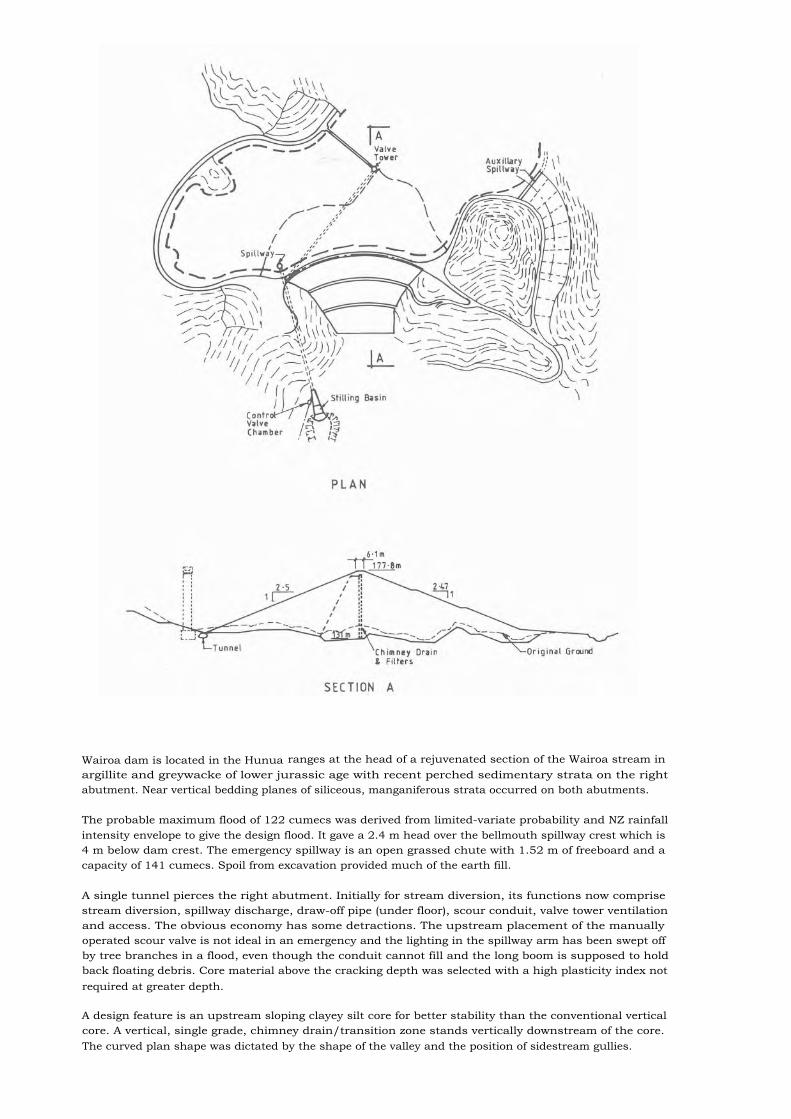
Wairoa dam is located in the Hunua ranges at the head of a rejuvenated section of the Wairoa stream inargillite and greywacke of lower jurassic age with recent perched sedimentary strata on the rightabutment. Near vertical bedding planes of siliceous, manganiferous strata occurred on both abutments.
The probable maximum flood of 122 cumecs was derived from limited-variate probability and NZ rainfallintensity envelope to give the design flood. It gave a 2.4 m head over the bellmouth spillway crest which is4 m below dam crest. The emergency spillway is an open grassed chute with 1.52 m of freeboard and acapacity of 141 cumecs. Spoil from excavation provided much of the earth fill.
A single tunnel pierces the right abutment. Initially for stream diversion, its functions now comprisestream diversion, spillway discharge, draw-off pipe (under floor), scour conduit, valve tower ventilationand access. The obvious economy has some detractions. The upstream placement of the manuallyoperated scour valve is not ideal in an emergency and the lighting in the spillway arm has been swept offby tree branches in a flood, even though the conduit cannot fill and the long boom is supposed to holdback floating debris. Core material above the cracking depth was selected with a high plasticity index notrequired at greater depth.
A design feature is an upstream sloping clayey silt core for better stability than the conventional verticalcore. A vertical, single grade, chimney drain/transition zone stands vertically downstream of the core.The curved plan shape was dictated by the shape of the valley and the position of sidestream gullies.

7. Mangatangi Dam
Location or Map Refs NZMS 260 S12 067 516Nearest City ManakauRiver MangatangiPurpose Urban water supply and flood controlCatchment area sq km 39.17Years of construction 1969 - 1977Type and foundation Earth on rock/soilHeight and crest length m 78 x 332
Volume of dam cu metres x 1000 2,140Spillway type UncontrolledSpillway max. discharge capacity cumecs 510Reservoir capacity cu metres x 1000 37,000Reservoir area sq metres x 1000 1,700Owner Auckland Regional AuthorityEngineering by ARA/Tonkin & TaylorConstruction by Green & McCahill

Argillite and interbedded coarse grained greywacke of the late Jurassic age, in all stages of weatheringfrom clayey silt to unweathered rock in the riverbed, forms the steeply sided dam site in the Hunua -Wharekawa ranges. The poor durability of the argillite rock contrasts its eminent suitability in theweathered form for earth fill. The crystalline greywacke on the other hand made first class riprap andchimney drain but in the weathered form it was wet in situ and being mixed with hard rounded cobbles,was unsuitable for the embankment. Geologically recent greywacke sediments and small pockets of
Taupo volcanic ash were also encountered.
The design flood was the probable maximum derived from limited variate probability and NZ envelope ofmaximum rainfall intensity. It used 3.05 m of the 4.5 m of freeboard available. The emergency spillway isan open grassed chute with an erodible embankment at design flood level. Excavation of the chuteprovided much of the fill for the dam shoulders.
A single tunnel pierces the right abutment. Its functions included river diversion, spillway discharge, scourconduit, valve tower ventilation and emergency assess. The upstream placement of the motor drivenscour valve is an undesirable aspect in view of possible failure under emergency conditions. The 3000 mdraw-off tunnel too has been criticised for emerging at the valve tower base instead of a downstreamposition. The stilling basin features a deflector hood to force a hydraulic jump in order to shorten thestructure. Modern trends suggest a ski jump would have been more suitable and less prone to damage.
An upstream sloping clayey silt core gives better stability than the more unusual vertical core. Highplasticity core material largely of recent sedimentary origin required stockpiling, discing and drying. Thehigh plasticity below the cracking depth has been the subject of some criticism because of its high cost andpotential for differential settlement. Seepage through the abutments and contact zone was kept to verylow figures by means of (a) high plasticity fill against the closely jointed rock in the contact zone and (b)clay blanketing of excavated upstream abutment slopes. A double layer transition chimney drain standsvertically at the downstream side of the core. In combination with extensive downstream shoulder contactdrains it drains safely any seepage through the core and abutments.

8. Kapukapu Detention Dam
Location or Map Refs NZMS 260 T13 484 231Nearest City PaeroaRiver Kapukapu StreamPurpose Flood controlCatchment area sq km 1.94Years of construction 1987 - 1988Type and foundation Compacted earth on weathered Andesite and
Andesite Breccia soilHeight and crest length m 15 x 200Volume of dam cu metres x 1000 60Spillway type UncontrolledSpillway max. discharge capacity cumecs 47 at 1.0 m depthReservoir capacity cu metres x 1000 140Reservoir area sq metres x 1000 42.5Owner Hauraki Catchment BoardEngineering by Hauraki Catchment Board StaffConstruction by D D Fenton & Sons/Hauraki Catchment Board

Plan
The Kapukapu Detention Dam is located in the lower valley 01 this steep catchment of theKapukapu Stream on the Coromandel Range and is immediately downstream of the confluence of theKapukapu and a small tributary. Both streams form a broad ponding area within the bounding ridges.The site largely consists of clays formed from weathered andesite and ash, with some andesitic gravels inthe bed of the valley.
The dam itself is a simple compacted earth embankment. Borrow material came primarily from within theponding area and from the spillway channel. Bank batters are relatively flat to minimise maintenance,while allowing continued use within the present farming situation. The culvert is a standard 1050 mmdiameter RRJRC pipe on a concrete mattress. The flow is restricted to the design four cumecs by anorifice plate at the inlet.
The dam is keyed into the gravels in the floor of the valley, with a cut off trench up to six metres deep.Construction of the dam was undertaken by conventional earthmoving machinery, being excavator anddump truck for the foundation, and motorscrapers for the major earth fill.
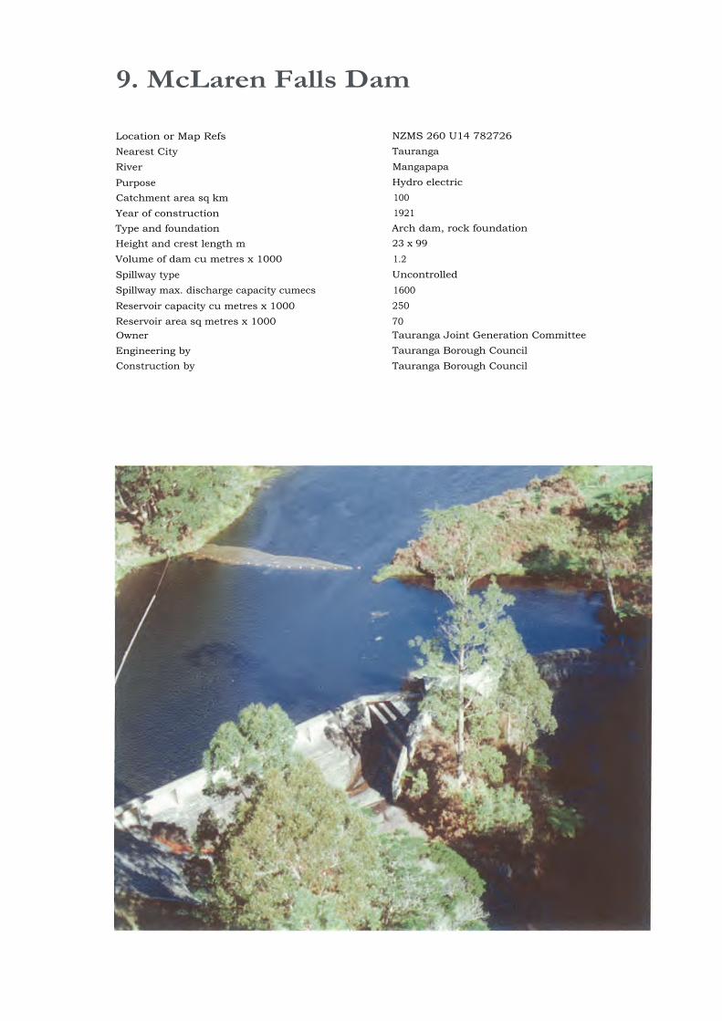
9. McLaren Falls Dam
Location or Map Refs NZMS 260 U14 782726Nearest City TaurangaRiver Mangapapa
Purpose Hydro electricCatchment area sq km 100Year of construction 1921Type and foundation Arch dam, rock foundationHeight and crest length m 23 x 99Volume of dam cu metres x 1000 1.2Spillway type UncontrolledSpillway max. discharge capacity cumecs 1600Reservoir capacity cu metres x 1000 250Reservoir area sq metres x 1000 70Owner Tauranga Joint Generation CommitteeEngineering by Tauranga Borough CouncilConstruction by Tauranga Borough Council

McLaren Falls dam was designed and built by Tauranga Borough Council in 1921 under engineeringdirection of Mr Lloyd Mandeno. This construction was part of an electricity generation scheme, dammingthe Mangapapa River to form a storage reservoir known as Lake McLaren. Additions were made to theseworks in 1978 when the spillway part was raised 2 metres and the dam crest modified. These alterationsincreased storage levels by 2 metres and were part of the diversion of Lake McLaren into a new powerdevelopment.
A notable feature of the original construction is the use of low strength aggregates for concrete.Although only 22 km from Tauranga there was no roading in the area at the time and access to the sitewas very difficult. This prohibited the importing of quality stone so local rhyolite with low compressivestrength was quarried on site and a higher cement content used to provide required concrete strength.This concrete work was cored and tested before additions were made in 1978 and found to have improvedconsiderably with age.
Later additions comprised raising the spillway section until level with the arch dam crest. The dam crestwas reshaped to provide spillover suitability. Both dam and spillway sections now retain water to thesame level and both act as overflow spillways in flood.

10. Mangaonui Dam
Location or Map Refs NZMS 260 U15 777 661Nearest City TaurangaRiver MangaonuiPurpose Hydro ElectricCatchment area sq km 5.2 (Fed by diversion tunnels from adjacent
catchments)Years of construction 1970 - 1972Type and foundation Earth dam rock/soil foundationHeight and crest length m 29 x 134Volume of dam cu metres x 1000 101Spillway type Controlled by a single inflatable rubber dam in
spillway channelSpillway max. discharge capacity cumecs 125Reservoir capacity cu metres x 1000 370Reservoir area sq metres x 1000 78Owner Tauranga Joint Generation CommitteeEngineering by Mandeno Chitty & BellConstruction by Canadian Construction Company
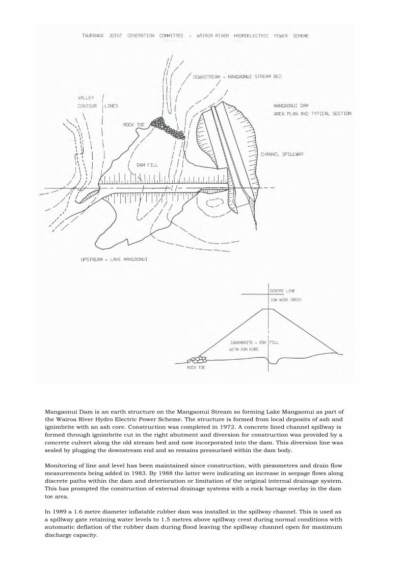
Mangaonui Dam is an earth structure on the Mangaonui Stream so forming Lake Mangaonui as part ofthe Wairoa River Hydro Electric Power Scheme. The structure is formed from local deposits of ash andignimbrite with an ash core. Construction was completed in 1972. A concrete lined channel spillway isformed through ignimbrite cut in the right abutment and diversion for construction was provided by aconcrete culvert along the old stream bed and now incorporated into the dam. This diversion line wassealed by plugging the downstream end and so remains pressurised within the dam body.
Monitoring of line and level has been maintained since construction, with piezometres and drain flowmeasurements being added in 1983. By 1988 the latter were indicating an increase in seepage flows alongdiscrete paths within the dam and deterioration or limitation of the original internal drainage system.This has prompted the construction of external drainage systems with a rock barrage overlay in the damtoe area.
In 1989 a 1.6 metre diameter inflatable rubber dam was installed in the spillway channel. This is used asa spillway gate retaining water levels to 1.5 metres above spillway crest during normal conditions withautomatic deflation of the rubber dam during flood leaving the spillway channel open for maximumdischarge capacity.

11. Matahina Dam
Location or Map Refs NZMS 260 V16 745 011Nearest City RotoruaRiver RangitaikiPurpose Hydro ElectricYears of construction 1961 - 1967Type and foundation Rock shoulder with earth core, compact tertiary
alluvials.Height and crest length m 86 x 345Volume of dam cu metres x 1000 4,200Spillway type Surface chute with ski-jump type bucketSpillway gates 3 radial gates each 12.5 m high, 8.5 m wideSpillway max. discharge capacity cumecs 1980Reservoir capacity cu metres x 1000 33,000Owner Electricity Corporation of NZ LtdEngineering by Civil works - Ministry of Works,
Electrical works - New Zealand ElectricityDepartment
Construction by Civil works - Ministry of Works,Electrical works - New Zealand Electricity
Department

The Matahina Dam has been built at a site where the Rangitaiki River has cut a gorge completelythrough an extensive sheet of volcanic rock (ignimbrite). Dam abutments are columnar jointed hard rockat upper levels but compact gravels, sands, and silty clays of Tertiary age at lower levels. A majortranscurrent fault traverses the rock of the left abutment approximately 500 metres from the dam andsplinter faults from this feature intersect within the dam foundation.
The dam has shells of hard ignimbrite rock and transition zones of the finer and softer grades of the samematerial. The central core of rolled weathered greywacke (saprolite) is of moderate width (0.33 head) andis inclined slightly downstream. It is extending downwards into the foundation sediments by a 6 metredeep cut-off plastic concrete. This cut-off is extended under the rock on the right abutment by anarticulated concrete tongue wall. Further protection against underseepage is provided by a curtain ofdrain wells on the downstream side and extending 30 metres into the foundations. Dam and foundationsare extensively instrumented with piezometers.
Very extensive grouting was required to seal or consolidate the open columnar jointed rock of theabutments. Over 15,000 tonnes of cement was used in curtain grouting with an average consumption of1.28 tonnes per sq metre on the right abutment. Consolidation grouting below structures used a further4,000 tonnes.
The site is equipped with five strong motion accelerographs, three within the dam and two at theabutments. A large array of surface markers on the dam and concrete structures is tied into a widespread geodetic network. This network monitors movement on the transcurrent fault as well as of thedam.
The dam withstood a major earthquake in March 1987. The maximum acceleration experienced at thedam crest was 0.42g horizontally and 0.29g vertically. Major repair works were undertaken in 1988.

12. Karapiro Dam
Location or Map Refs NZMS 206 T15 392 160Nearest City HamiltonRiver WaikatoPurpose Hydro ElectricYears of construction 1940 -1947Type and foundation Arch with gravity abutments, greywacke rockHeight and crest length m 66.8 x 332Volume of dam cu metres x 1000 153Spillway type Surface chute, syphonSpillway gates 4 vertical lift gates each 7.0 metres high, 6.4
metres wideSpillway max. discharge capacity cumecs 747 spillway, 102 syphonsReservoir capacity cu metres x 1000 87,000Reservoir area sq metres x 1000 7,700Owner Electricity Corporation of NZ LtdEngineering by State Hydro Electric DepartmentConstruction by State Hydro Electric Department

Karapiro is the last hydro station down the Waikato River from Taupo. It was planned prior to the1939-45 war but because of the shortage of materials and manpower was not completed until 1947. Thedifficult supply position overseas also led to the policy of New Zealand design and fabrication ofmechanical parts. The exception to this rule was the 50 ton diversion gate which is of UK origin.
The dam was designed as a variable radius arch with a high span to height ratio. The right abutmentgravity section incorporates the power intakes, spillway and syphons. An unusual feature of this block isthat an inspection and drainage gallery in the shape of a quarter circle is located external to the structureon the upstream face.
When the lake was filled, an old hydro station, Horohora built in 1910-13 was drowned. The lake is nowthe site of an international standard rowing course.
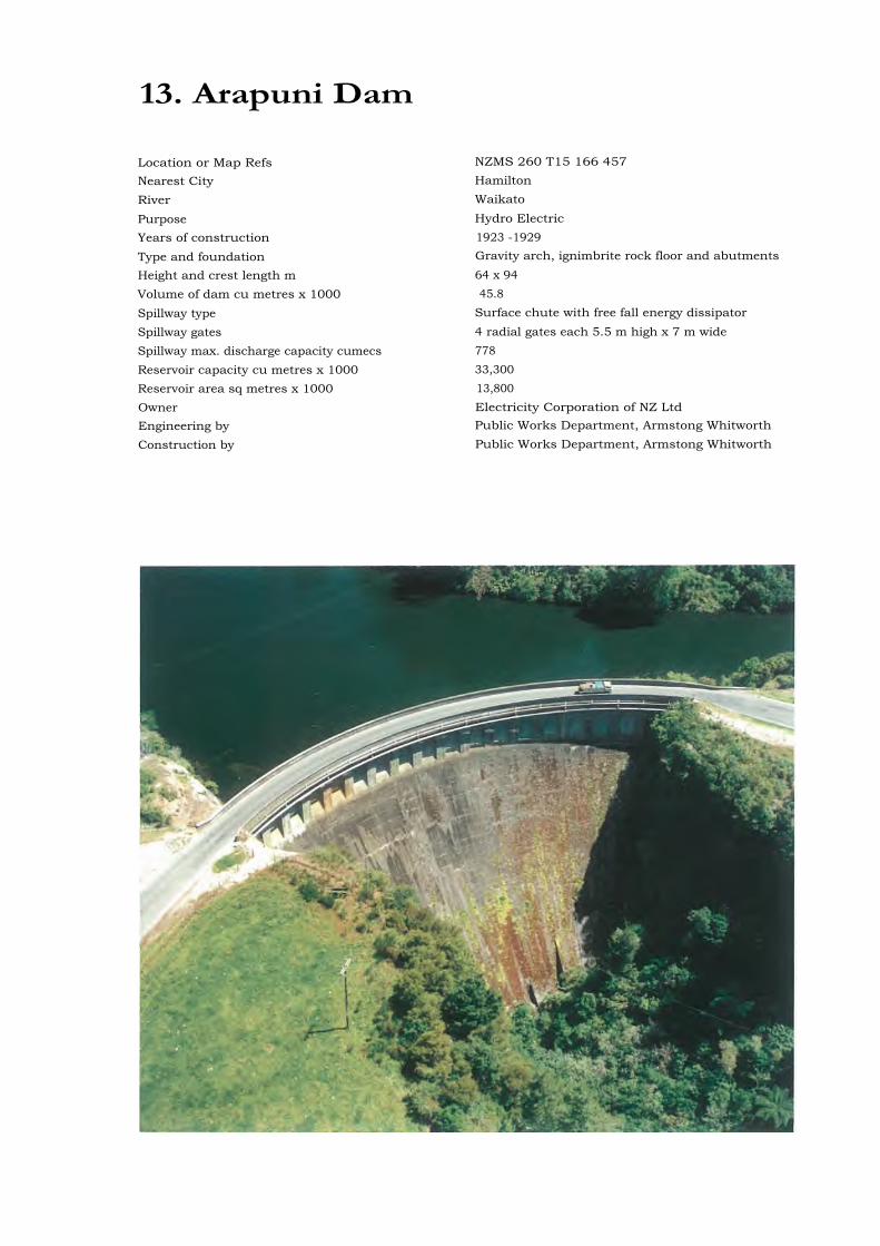
13. Arapuni Dam
Location or Map Refs NZMS 260 T15 166 457
Nearest City Hamilton
River Waikato
Purpose Hydro ElectricYears of construction 1923 -1929
Type and foundation Gravity arch, ignimbrite rock floor and abutments
Height and crest length m 64 x 94Volume of dam cu metres x 1000 45.8
Spillway type Surface chute with free fall energy dissipator
Spillway gates 4 radial gates each 5.5 m high x 7 m wideSpillway max. discharge capacity cumecs 778Reservoir capacity cu metres x 1000 33,300Reservoir area sq metres x 1000 13,800Owner Electricity Corporation of NZ LtdEngineering by Public Works Department, Armstong Whitworth
Construction by Public Works Department, Armstong Whitworth

Arapuni Dam, the first government built hydro station to be operated on the Waikato River, is located ina narrow rock gorge. A site feature is an old, higher level watercourse which leaves the river upstream ofthe dam site and rejoins the river downstream of the gorge.
The site was ideal for the type of development adopted, namely a high dam in the gorge with the headraceand spillway located in the old natural watercourse. In the final design, the power intake was located 1.2km down the tailrace from the dam and the powerhouse in the gorge, enabling a gross head of 53 metresto be developed for power.
The station was first operated in 1929 without a headrace lining and without any surface protection of thesection of the watercourse where several falls previously existed. After approximately one year's operationthere was a forced close down because of the tilting of the rock section between the headrace and theriver gorge brought about by water ingress into the rock jointing system. There was also massive erosionof the old watercourse with the passage of flood discharges over the waterfall length. The headrace waslined and the spillway section of the old channel concreted to enable the station to be reopened in 1932.
A new spillway by-passing the existing headrace was built in 1988-89. Replacement of the existingheadrace lining is planned for 1989-90.
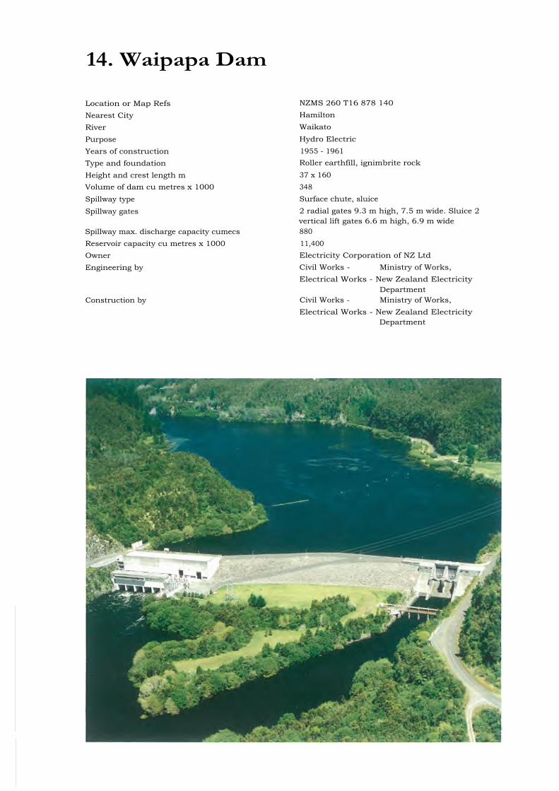
14. Waipapa Dam
Location or Map Refs NZMS 260 T16 878 140
Nearest City Hamilton
River Waikato
Purpose Hydro ElectricYears of construction 1955 - 1961Type and foundation Roller earthfill, ignimbrite rock
Height and crest length m 37 x 160Volume of dam cu metres x 1000 348Spillway type Surface chute, sluice
Spillway gates 2 radial gates 9.3 m high, 7.5 m wide. Sluice 2vertical lift gates 6.6 m high, 6.9 m wide
Spillway max. discharge capacity cumecs 880Reservoir capacity cu metres x 1000 11,400Owner Electricity Corporation of NZ LtdEngineering by Civil Works - Ministry of Works,
Electrical Works - New Zealand ElectricityDepartment
Construction by Civil Works - Ministry of Works,Electrical Works - New Zealand Electricity
Department

Waipapa Dam is one of eight dams in the Waikato River Hydro Power Development Scheme which tookplace over the period 1923 (Arapuni dam) to 1964 (Aratiatia dam). The site lies where the river haseroded almost through the extensive sheets of volcanic rock (ignimbrites) which occur in the centralNorth Island of New Zealand. A remnant of rock, some 10 metres thick remains across the gorge for ashort distance at the dam site. The underlying materials are compact semi-permeable sediments ofTertiary age. The ignimbrite is hard, well fused and with a well developed pattern of columnar joints. No
, major tectonic features exist near the site.
The dam is a rolled fill structure with a wide core of crushed soft ignimbrite. It is extended down to therock remnant beneath the river bed by a rolled fill cut-off placed in open trench. Elsewhere it is foundedon the compact pumiceous alluvials of the river bed and is supported on the downstream side by a wideberm of compacted fill. The total height from crest to bottom of cut-off trench is 37 metres for anoperating head of 15 metres.
Underseepage is controlled by a grout curtain through the rock remnant and into the rock of bothabutments and seepage pressures by drainage. The dam is instrumented with piezometers and hydrostaticsettlement cells.
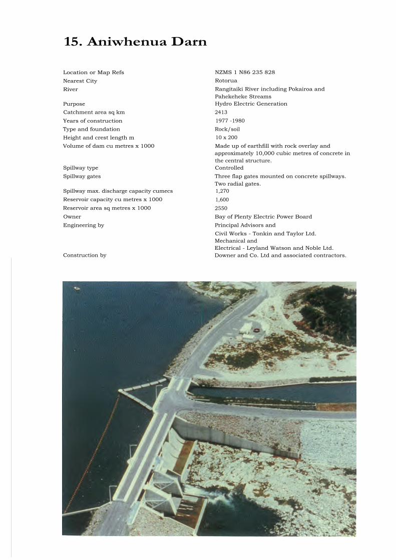
15. Aniwhenua Darn
Location or Map Refs NZMS 1 N86 235 828Nearest City Rotorua
River Rangitaiki River including Pokairoa andPahekeheke Streams
Purpose Hydro Electric GenerationCatchment area sq km 2413Years of construction 1977 -1980Type and foundation Rock/soilHeight and crest length m 10 x 200Volume of dam cu metres x 1000 Made up of earthfill with rock overlay and
approximately 10,000 cubic metres of concrete inthe central structure.
Spillway type ControlledSpillway gates Three flap gates mounted on concrete spillways.
Two radial gates.Spillway max. discharge capacity cumecs 1,270Reservoir capacity cu metres x 1000 1,600Reservoir area sq metres x 1000 2550Owner Bay of Plenty Electric Power BoardEngineering by Principal Advisors and
Civil Works - Tonkin and Taylor Ltd.Mechanical andElectrical - Leyland Watson and Noble Ltd.
Construction by Downer and Co. Ltd and associated contractors.
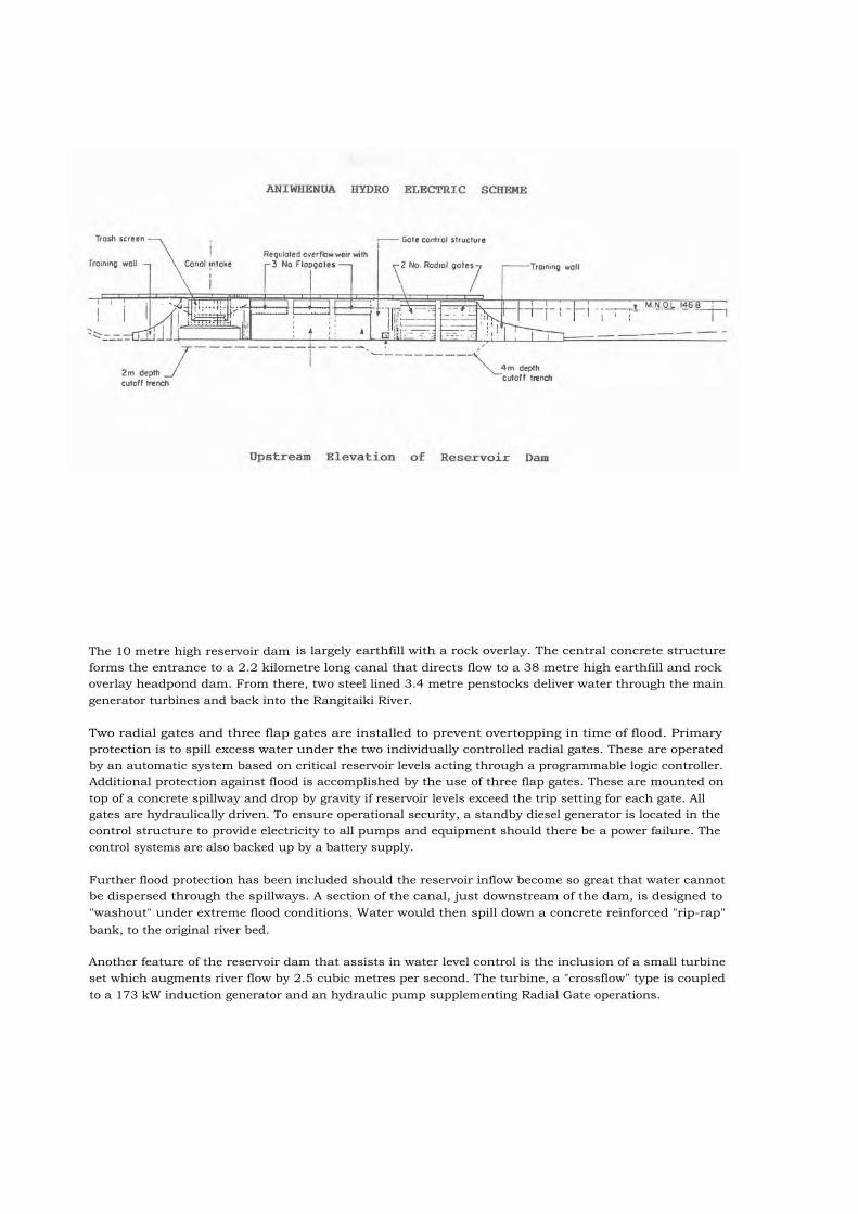
The 10 metre high reservoir dam is largely earthfill with a rock overlay. The central concrete structureforms the entrance to a 2.2 kilometre long canal that directs flow to a 38 metre high earthfill and rockoverlay headpond dam. From there, two steel lined 3.4 metre penstocks deliver water through the maingenerator turbines and back into the Rangitaiki River.
Two radial gates and three flap gates are installed to prevent overtopping in time of flood. Primaryprotection is to spill excess water under the two individually controlled radial gates. These are operatedby an automatic system based on critical reservoir levels acting through a programmable logic controller.Additional protection against flood is accomplished by the use of three flap gates. These are mounted ontop of a concrete spillway and drop by gravity if reservoir levels exceed the trip setting for each gate. Allgates are hydraulically driven. To ensure operational security, a standby diesel generator is located in thecontrol structure to provide electricity to all pumps and equipment should there be a power failure. Thecontrol systems are also backed up by a battery supply.
Further flood protection has been included should the reservoir inflow become so great that water cannotbe dispersed through the spillways. A section of the canal, just downstream of the dam, is designed to"washout" under extreme flood conditions. Water would then spill down a concrete reinforced "rip-rap"bank, to the original river bed.
Another feature of the reservoir dam that assists in water level control is the inclusion of a small turbineset which augments river flow by 2.5 cubic metres per second. The turbine, a "crossflow" type is coupledto a 173 kW induction generator and an hydraulic pump supplementing Radial Gate operations.

16. Maraetai Dam
Location or Map Refs NZMS 260 T16 022 611Nearest City RotoruaRiver WaikatoPurpose Hydro ElectricYears of construction 1947 - 1952Type and foundation Concrete arch, ignimbrite rockHeight and crest length m 87 x 133Volume of dam cu metres x 1000 112.4Spillway type Inclined shaft, horizontal tunnelSpillway gates Three vertical lift gates 10.7 m high, 4.4 m wideSpillway max. discharge capacity cumecs 850Reservoir capacity cu metres x 1000 94,200Reservoir area sq metres x 1000 5000Owner Electricity Corporation of NZ LtdEngineering by Civil Works - Ministry of Works,
Electrical Works - State Hydro-electricDepartment
Construction by Civil Works - Ministry of Works,Electrical Works - State Hydro-electric
Department

Maraetai Dam is one of eight dams making up the Waikato River Hydro Power Development. The site isin a narrow gorge eroded into an extensive sheet of volcanic rock (ignimbrite). The rock is heavilydissected by columnar joints but the site is free of any major tectonic features. The Maraetai Ipowerhouse spans the gorge immediately downstream of the dam while the Maraetai II powerhouse issituated along the left bank of the gorge some 500 metres downstream of the dam. Abutments werestrengthened by consolidation grouting and leakage is controlled by a grout curtain totalling 100,000 sqmetres in area. Seepage forces are controlled by a system of drainage drives and drain holes on thedownstream side of the grout curtain.
The dam is a conventional multi-centre circular arch with a base thickness of 15 metres and a crestthickness of 3 metres. It was designed by the Ministry of Works and Development with assistance fromUSBR. Hydraulic cylinders for operating the deep set intake gates are mounted in the upstream face ofthe dam.
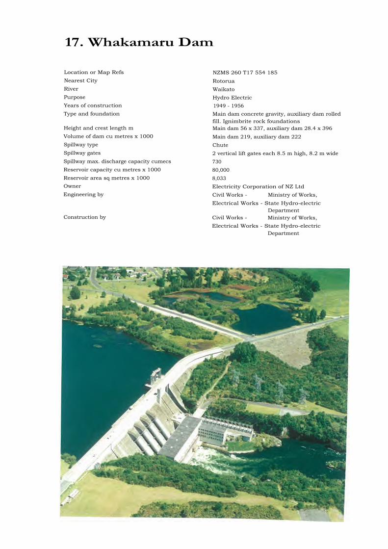
17. Whakamaru Dam
Location or Map Refs NZMS 260 T17 554 185Nearest City RotoruaRiver WaikatoPurpose Hydro ElectricYears of construction 1949 - 1956Type and foundation Main dam concrete gravity, auxiliary dam rolled
fill. Ignimbrite rock foundationsHeight and crest length m Main dam 56 x 337, auxiliary dam 28.4 x 396Volume of dam cu metres x 1000 Main dam 219, auxiliary dam 222Spillway type ChuteSpillway gates 2 vertical lift gates each 8.5 m high, 8.2 m wideSpillway max. discharge capacity cumecs 730Reservoir capacity cu metres x 1000 80,000Reservoir area sq metres x 1000 8,033Owner Electricity Corporation of NZ LtdEngineering by Civil Works - Ministry of Works,
Electrical Works - State Hydro-electricDepartment
Construction by Civil Works - Ministry of Works,Electrical Works - State Hydro-electric
Department

Whakamaru Dam is one of eight dams in the Waikato River Hydro Power Development Scheme. Thevolcanic rocks at the site (ignimbrites) are extensively columnar jointed and have relatively low modulus.Extensive tunnels were driven into the foundations and backfilled with concrete to improve the rockmodulus. Consolidation and curtain grouting were carried out to further improve the rock modulus andto control leakage under the dam and abutments. The site is free of major tectonic features but acontinuous joint runs parallel to the tailrace and spillway on the left bank. This joint is pinned by drivesbackfilled with reinforced concrete.
The main dam has a vertical upstream face and a downstream batter of 0.837:1 to allow for the low massdensity of the concrete (2.18 t/cu.m) and the low modulus of the foundation rock (700 MPa). Theauxiliary dam is a zoned rolled fill in the valley of a tributary stream on the left bank. a rolled fill wingdam and cut-off extends the main dam into the right abutment. Piezometers are installed under bothdams and in the impermeable zones of the auxiliary dam.
Because of the low modulus of the foundation rock the dam is provided with open joints on either side ofthe diversion/spillway block and at the right abutment. These joints provide compliance should significantdifferential deflections occur. The powerhouse is similarly isolated from the dam structure.

18. Aratiatia Dam
Location or Map Refs NZMS 260 U17 922 879Nearest City RotoruaRiver WaikatoPurpose Hydro ElectricYears of construction 1959 - 1964Type and foundation Concrete gravity, rhyolite rockHeight and crest length m Dam 17.8 m high x 16.5 wide, overflow section
5 m high x 120 longVolume of dam cu metres x 1000 5.0Spillway type Chute with supplementary free overflowSpillway gates 2 radial gates each 9.1 m high x 5.5 m wideSpillway max. discharge capacity cumecs 550, overflow dam 250Owner Electricity Corporation of NZ Ltd
Engineering by Civil Works - Ministry of Works,Electrical Works - New Zealand Electricity
DepartmentConstruction by Civil Works - Ministry of Works,
Electrical Works - New Zealand ElectricityDepartment

Aratiatia Dam is the latest of eight dams making up the Waikato River Hydro Power Development. Theproject develops the potential of a natural cascade formed where bands of hard rhyolite rock haveintruded into weak pyroclastic material (volcanic tuffs). The headrace tunnel is driven through very mixedvolcanic materials with both flow banded and brecciated structures. Hydrothermal leaching is frequentand sometimes intense. No major tectonic faulting affects the site.
The dam is a low concrete structure with spillweir crest along the left bank. The spillway structureoccupies the full width of the river bed and the dam continues as a rolled fill embankment and cut-off for100 metres on the right bank. The spillway structure contains two radial gates 5.5 metres wide and 9.1metres high which discharge into a short dentated sill stilling basin with its invert 9 metres below spillwaycrest. From there spill energy is dissipated down the natural rapids in the river bed. The dischargecapacity of the gates is 550 cumecs and is supplemented by free flow over the left bank weir crest at floodlevels.
The Aratiatia Rapids on which the station is built are a scenic attraction and statutory consents requirethat natural flow down the rapids takes place at pre-determined times of day. The spillway gates are indaily use to meet this requirement and their size and the left bank spillweir were chosen to ensure thatthis condition would be met under all circumstances.
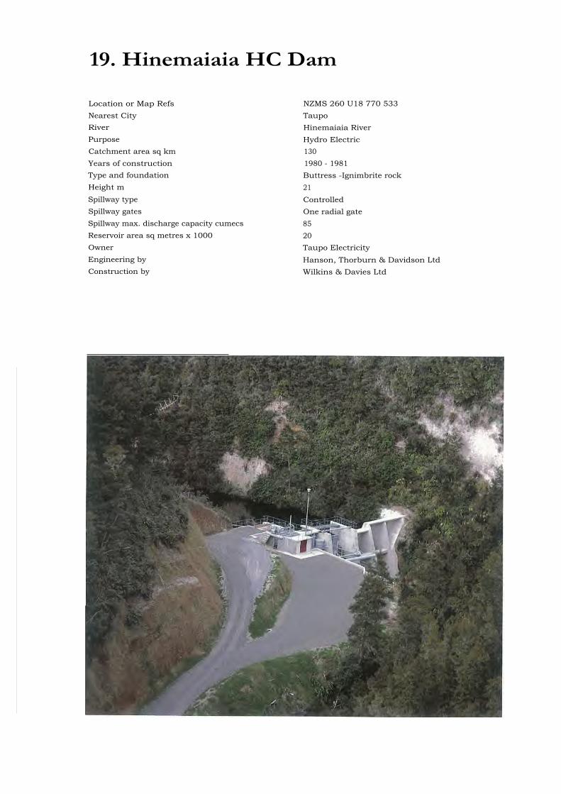
19. Hinemaiaia HC Dam
Location or Map Refs NZMS 260 U18 770 533Nearest City TaupoRiver Hinemaiaia RiverPurpose Hydro ElectricCatchment area sq km 130Years of construction 1980 - 1981Type and foundation Buttress -Ignimbrite rockHeight m 21Spillway type ControlledSpillway gates One radial gateSpillway max. discharge capacity cumecs 85Reservoir area sq metres x 1000 20Owner Taupo ElectricityEngineering by Hanson, Thorburn & Davidson LtdConstruction by Wilkins & Davies Ltd

The HC development is one of three hydro power schemes on the Hinemaiaia River. The HC dam hasbeen built in a very narrow ignimbrite gorge some 27 m deep. The lower section of the dam extendshorizontally between the gorge walls while the upper section has been designed as a buttressed wall.
An ogee spillway has been incorporated into the dam structure to discharge flood waters and the weightcounterbalanced radial gate controlling the impounding waters self adjusts to spill flood waters. The 2 haof water confined in the lake provide negligible storage and the HC Station is operated in tandem with theupstream HA Station.
From the intake gate and screen 457 m of 2.0 m diameter concrete conduit and 84 m of 1.8 m diameterpenstock carry the water to a circular section power station constructed to cope with the high river floodrise. A single penstock leads to the powerstation where it is bifurcated to lead to two Francis turbines ona common horizontal shaft driving a 2850 kW induction generator. The turbines can be operatedindividually or together.
A feature of the dam is the radial gate designed to prevent the level of the lake from rising too high. Atinflows higher than approximately 11 cumecs (the maximum machine flow) the gate will open sufficient topass the excess flow, modulating in response to changes in lake level.

20. Rangipo Dam
Location or Map Refs NZMS 260 T20 314 481Nearest City RotoruaRiver TongariroPurpose Hydro ElectricYears of construction 1975 - 1983
Type and foundation Mass concrete free overflow, coarse andesiteriver gravels
Height and crest length m 23 x 150Volume of dam cu metres x 1000 81Spillway type Free overflow, gated sluiceSpillway gates 3 Sluice gates each 6.0 m high x 6.33 m wideSpillway max. discharge capacity cumecs Spillway 570, sluiceway 990Reservoir capacity cu metres x 1000 456Owner Electricity Corporation of NZ LtdEngineering by Civil Works: - Ministry of Works and
Development,Electrical Works: - New Zealand Electricity
DepartmentConstruction by Civil Works: - Ministry of Works and
Development,Electrical Works: - New Zealand Electricity
Department
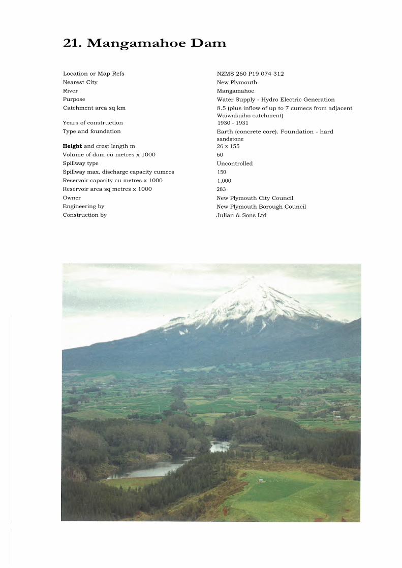
21. Mangamahoe Dam
Location or Map Refs NZMS 260 P19 074 312Nearest City New PlymouthRiver MangamahoePurpose Water Supply - Hydro Electric GenerationCatchment area sq km 8.5 (plus inflow of up to 7 cumecs from adjacent
Waiwakaiho catchment)Years of construction 1930 - 1931Type and foundation Earth (concrete core). Foundation - hard
sandstoneHeight and crest length m 26 x 155Volume of dam cu metres x 1000 60Spillway type UncontrolledSpillway max. discharge capacity cumecs 150Reservoir capacity cu metres x 1000 1,000Reservoir area sq metres x 1000 283Owner New Plymouth City CouncilEngineering by New Plymouth Borough CouncilConstruction by Julian & Sons Ltd
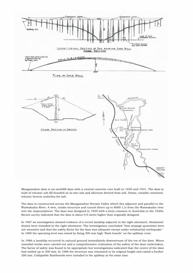
Mangamahoe dam is an earthfill dam with a central concrete core built in 1930 and 1931. The dam isbuilt of volcanic ash fill founded on in-situ ash and alluvium derived from ash. Dense, variable cemented,volcanic breecia underlies the ash.
The dam is constructed across the Mangamahoe Stream Valley which lies adjacent and parallel to theWaiwakaiho River. A weir, intake structure and tunnel divert up to 8000 1/s from the Waiwakaiho riverinto the impoundment. The dam was designed in 1929 with a form common to Australia in the 1920s.Recent survey indicated that the dam is about 0.9 metre higher than originally designed.
In 1967 an investigation showed evidence of a recent landslip adjacent to the right abutment. Horizontaldrains were installed in the right abutment. The investigation concluded "that seepage quantities werenot excessive and that the safety factor for the dam was adequate except under substantial earthquake."In 1980 the operating level was raised by fixing 300 mm high "flash boards" on the spillway crest.
In 1986 a landslip occurred in natural ground immediately downstream of the toe of the dam. Minorremedial works were carried out and a comprehensive evaluation of the safety of the dam undertaken.The factor of safety was found to be appropriate but investigations indicated that the centre of the damhad settled up to 500 mm. In 1988 the structure was reinstated to its original height and raised a further200 mm. Collapsible flashboards were installed to the spillway at the same time.
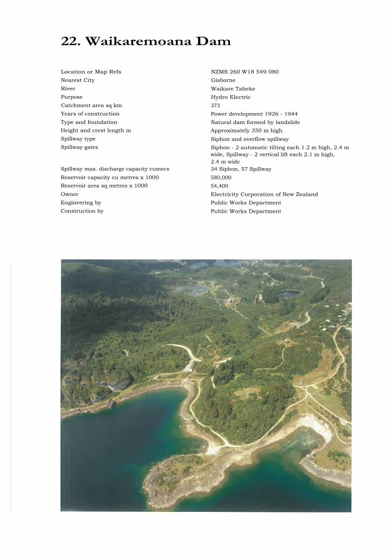
22. Waikaremoana Dam
Location or Map Refs NZMS 260 W18 549 080Nearest City GisborneRiver Waikare TahekePurpose Hydro ElectricCatchment area sq km 373Years of construction Power development 1926 - 1944Type and foundation Natural dam formed by landslideHeight and crest length m Approximately 350 m highSpillway type Siphon and overflow spillwaySpillway gates Siphon - 2 automatic tilting each 1.2 m high, 2.4 m
wide, Spillway - 2 vertical lift each 2.1 m high,2.4 m wide
Spillway max. discharge capacity cumecs 34 Siphon, 57 SpillwayReservoir capacity cu metres x 1000 580,000Reservoir area sq metres x 1000 54,400Owner Electricity Corporation of New ZealandEngineering by Public Works DepartmentConstruction by Public Works Department

Lake Waikaremoana, which is 260 metres maximum depth, was formed by a gigantic slip which blockedthe channel of the Waikare-Taheke river. The slip acts as a rock fill dam approximately 350 metres highfrom crest to toe. The material forming the slip is predominantly sandstone and siltstone derived fromthe original country rock mass.
The fall in the river valley below the dam has been utilised for three Power Station developments withtotal installed generation 124 MW. The total head is 453 metres which is available within the first 11.2km of river valley.
The intake to the upstream development is by tunnels driven through the rock landslip material. The firstsection is a single concrete lined tunnel, 16 metres operating head of 3 metres diameter and 210 metreslong. The tunnel then bifurcates to a steel lined gated section and two tunnels each 2.5 metres diameter,300 metres long. During the driving of these tunnels a number of zones containing water under pressurewere encountered.
Before the hydro development most of the catchment run-off was by leakage through the dam ofapproximately 20 cumecs. During periods of high inflow and consequent lake rise water overflowed over anatural outlet section. An extensive programme of lake sealing using graded materials has reducedleakage to approximately 30% of the former rate. A number of leakage paths through the dam are deepseated. This has limited attempts to locate and seal these leaks.
Checking the long term stability of the landslip is difficult because of its magnitude, difficulty indetermining representative material properties, mapping discontinuities with the mass, determining flowpaths, etc. The regular surveillance includes deformation survey and piezometric and flow measurements.There has been no apparent movement since first measurements were taken.
in 1931 an earthquake of intensity MM7 - MM8 was experienced, only superficial damage resulted. Thelake and surrounding land is a National Park.
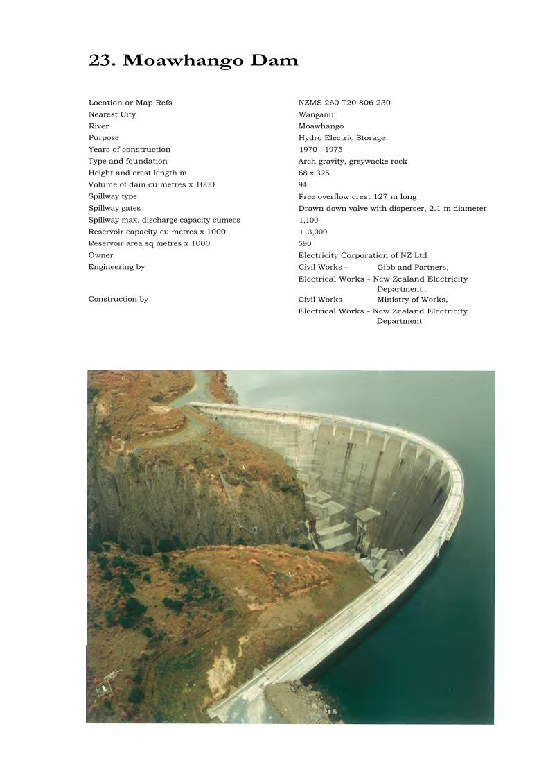
23. Moawhango Dam
Location or Map Refs NZMS 260 T20 806 230Nearest City WanganuiRiver MoawhangoPurpose Hydro Electric StorageYears of construction 1970 - 1975Type and foundation Arch gravity, greywacke rockHeight and crest length m 68 x 325Volume of dam cu metres x 1000 94Spillway type Free overflow crest 127 m longSpillway gates Drawn down valve with disperser, 2.1 m diameterSpillway max. discharge capacity cumecs 1,100Reservoir capacity cu metres x 1000 113,000Reservoir area sq metres x 1000 590Owner Electricity Corporation of NZ LtdEngineering by Civil Works - Gibb and Partners,
Electrical Works - New Zealand ElectricityDepartment .
Construction by Civil Works - Ministry of Works,Electrical Works - New Zealand Electricity
Department
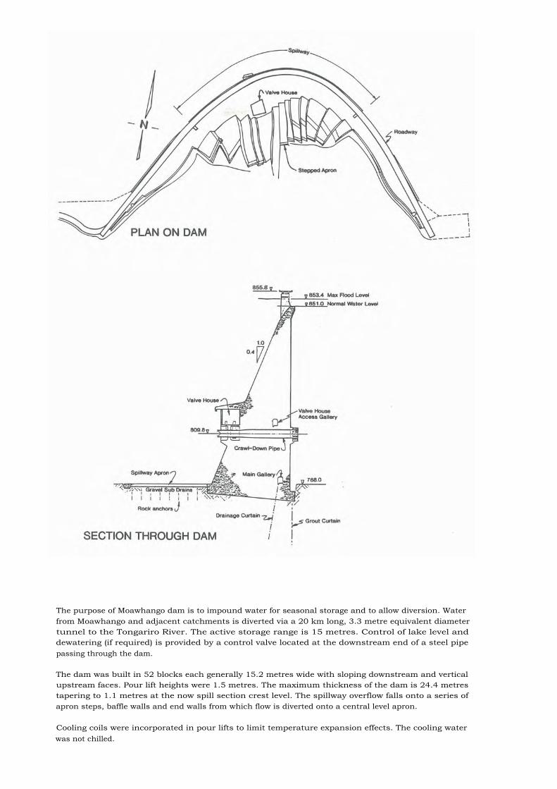
The purpose of Moawhango dam is to impound water for seasonal storage and to allow diversion. Waterfrom Moawhango and adjacent catchments is diverted via a 20 km long, 3.3 metre equivalent diametertunnel to the Tongariro River. The active storage range is 15 metres. Control of lake level anddewatering (if required) is provided by a control valve located at the downstream end of a steel pipepassing through the dam.
The dam was built in 52 blocks each generally 15.2 metres wide with sloping downstream and verticalupstream faces. Pour lift heights were 1.5 metres. The maximum thickness of the dam is 24.4 metrestapering to 1.1 metres at the now spill section crest level. The spillway overflow falls onto a series ofapron steps, baffle walls and end walls from which flow is diverted onto a central level apron.
Cooling coils were incorporated in pour lifts to limit temperature expansion effects. The cooling waterwas not chilled.

24. Patea Dam
Location or Map Refs 16 kms inland from HurleyvilleNZMS 1 N130 126 332
Nearest City Patea townRiver Patea
Purpose Hydro Electric Power GenerationCatchment area sq km 871Years of construction February 1982 to December 1983Type and foundation Compacted earth dam with central chimney drain
and downstream filter blanket placed on sandstonefoundations
Height and crest length m 83 x 190Volume of dam cu metres x 1000 1,200Spillway type Reinforced concrete chute with lower end flip
bucket plus auxiliary emergency and fuse plugspillways.
Spillway gates 2 hydraulically operated radial gatesSpillway max. discharge capacity cumecs Gated spillway 1080, emergency 2800Reservoir capacity cu metres x 1000 144,000Reservoir area sq metres x 1000 6450Owner Egmont Electric Power BoardEngineering by Beca, Carter, Hollings & Ferner LimitedConstruction by Downer and Company Limited

The dam impounding Lake Rotorangi, is founded on sandstone and is a compacted earthfill structuremade from local tertiary sandstone and siltstone materials. This is the first relatively high dam constructedin New Zealand using these materials.
A drainage feature is a central chimney drain constructed of graded aggregates and connected to ahorizontal blanket drain of high capacity in the downstream base of the dam. The upper part of thechimney is of double width and designed to collapse back into any crack which may form. Trench drainsare constructed on the surface of the side slope to avoid long term saturation of the downstreamshoulder.
Upstream and downstream surfaces of the dam are covered with a thick layer of crushed shell rock tocontrol erosion. This same material but in the form of large boulders is placed as rip-rap at the watersurface level.
The safety of the dam is dependant upon precluding over-topping. Flood flows are therefore dischargedin three stages. Annual mean river flow is 28 cumecs and the estimated 100 year flood 1030 cumecs.PMF is estimated at 2800 cumecs. The concrete spillway is designed to safely pass the 100 year flood butif the lake rises by more than 1 metre above nominal full level an auxiliary spillway set on a shell rock sillwill come into operation. Should the lake level continue to rise a fuse-plug spillway will be triggered.

25. Makara No. 1 Dam
Location or Map Refs NZMS 260 V22 411 363
Nearest City Hastings
River Makara Stream, Tukituki River
Purpose Flood ControlCatchment area sq km 13.3Years of construction 1981
Type and foundation Earth on SoilHeight and crest length m 12 x 135
Volume of dam cu metres x 1000 38Spillway type UncontrolledCulvert 2 m diameter cap. 29 cumecsSpillway max. discharge capacity cumecs 132Reservoir capacity cu metres x 1000 835Reservoir area sq metres x 1000 154Owner Hawkes Bay Catchment BoardEngineering by Hawkes Bay Catchment BoardConstruction by Simmons & Stephens and Edwards Bros
(concrete spillway)
Above Completed dam with embankment Below Dam in use immediatelygrassed 1989 following construction 1981

The Upper Makara Catchment Control Scheme consists of a series of dams for flood control purposes ofwhich the dam featured is the largest. The protection is required for the Lower Makara Stream. It hasbeen designed on the basis of containing the discharge up to spillway level of a 5 year return period eventwith the culvert discharging.
The dam is constructed with a dry clay silt blanket of 1 metre thickness across the full width of the basewith the main part of the dam being siltstone. The upstream face with a horizontal 4 metre width hasbeen constructed with a clay silt mix. The foundations are a yellow brown clayey silt overlying grey clayeysilt which was found to be soft in places. Allowance was made for settlement by arching the culvert andraising the centre of the dam.
There were construction difficulties with compaction of the siltstone because of hard lumps needing to bebroken down and problems with the clay silt mix needing to be dried before compaction on the upstreamface. The concrete spillway needed special attention with work starting on a pour before dawn andcontinuing into early morning to avoid the summer heat. The problems were not helped with the distancefrom the ready mix plant.
The spillway on the dam has not yet been in use although the water level has been close on occasions.
26. Tiritea - High Dam
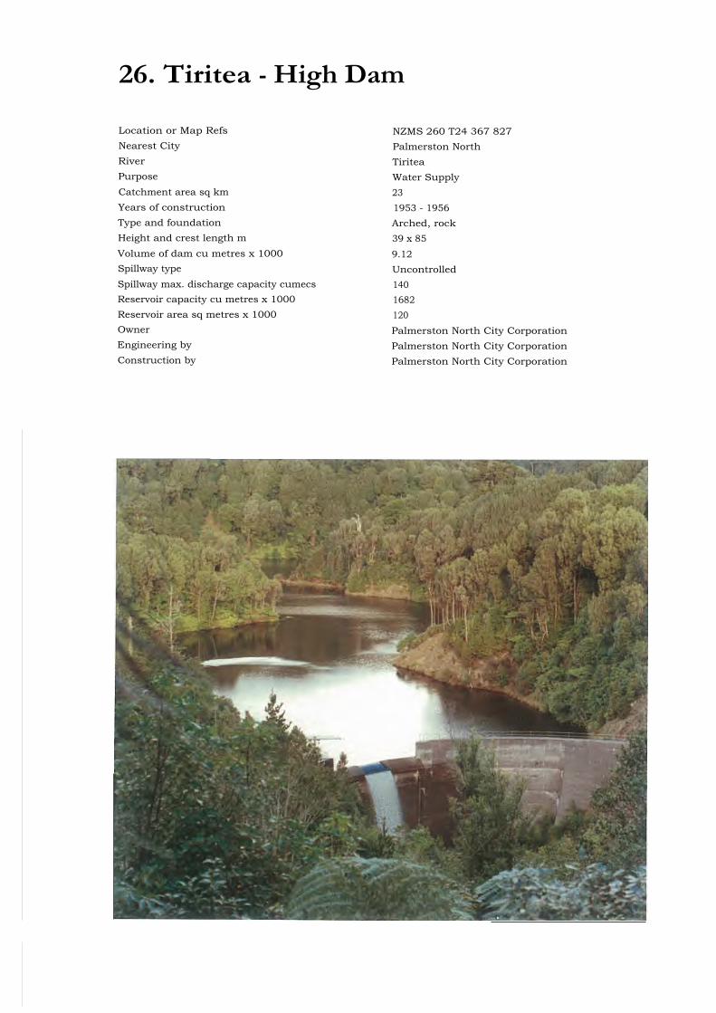
Location or Map Refs NZMS 260 T24 367 827Nearest City Palmerston NorthRiver TiriteaPurpose Water SupplyCatchment area sq km 23Years of construction 1953 - 1956Type and foundation Arched, rockHeight and crest length m 39 x 85Volume of dam cu metres x 1000 9.12Spillway type UncontrolledSpillway max. discharge capacity cumecs 140Reservoir capacity cu metres x 1000 1682Reservoir area sq metres x 1000 120Owner Palmerston North City CorporationEngineering by Palmerston North City CorporationConstruction by Palmerston North City Corporation
Tiritea Dam is the primary source of water to Palmerston North City satisfying on average 72% of thetotal water demand. It was built to overcome water shortages experience in the previous years and islocated in a narrow confined valley at the confluence of the main Tiritea and little Tiritea Streams. Thegeology consists of medium to fine grained greywacke with minor amounts of argillite and some minorpug filled discontinuous fracture planes. The upper left abutment area consists of jointed rock.
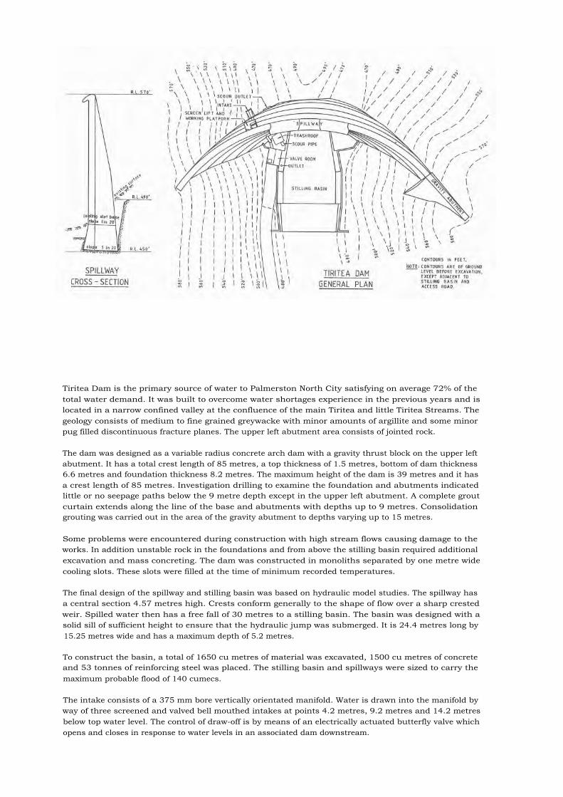
The dam was designed as a variable radius concrete arch dam with a gravity thrust block on the upper leftabutment. It has a total crest length of 85 metres, a top thickness of 1.5 metres, bottom of dam thickness6.6 metres and foundation thickness 8.2 metres. The maximum height of the dam is 39 metres and it hasa crest length of 85 metres. Investigation drilling to examine the foundation and abutments indicatedlittle or no seepage paths below the 9 metre depth except in the upper left abutment. A complete groutcurtain extends along the line of the base and abutments with depths up to 9 metres. Consolidationgrouting was carried out in the area of the gravity abutment to depths varying up to 15 metres.
Some problems were encountered during construction with high stream flows causing damage to theworks. In addition unstable rock in the foundations and from above the stilling basin required additionalexcavation and mass concreting. The dam was constructed in monoliths separated by one metre widecooling slots. These slots were filled at the time of minimum recorded temperatures.
The final design of the spillway and stilling basin was based on hydraulic model studies. The spillway hasa central section 4.57 metres high. Crests conform generally to the shape of flow over a sharp crestedweir. Spilled water then has a free fall of 30 metres to a stilling basin. The basin was designed with asolid sill of sufficient height to ensure that the hydraulic jump was submerged. It is 24.4 metres long by15.25 metres wide and has a maximum depth of 5.2 metres.
To construct the basin, a total of 1650 cu metres of material was excavated, 1500 cu metres of concreteand 53 tonnes of reinforcing steel was placed. The stilling basin and spillways were sized to carry themaximum probable flood of 140 cumecs.
The intake consists of a 375 mm bore vertically orientated manifold. Water is drawn into the manifold byway of three screened and valved bell mouthed intakes at points 4.2 metres, 9.2 metres and 14.2 metresbelow top water level. The control of draw-off is by means of an electrically actuated butterfly valve whichopens and closes in response to water levels in an associated dam downstream.
27. Mangahao (No. 2 Dam)
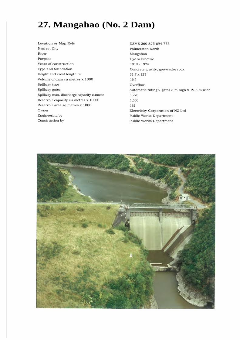
Location or Map Refs NZMS 260 S25 694 775Nearest City Palmerston NorthRiver MangahaoPurpose Hydro ElectricYears of construction 1919 - 1924Type and foundation Concrete gravity, greywacke rockHeight and crest length m 31.7 x 123Volume of dam cu metres x 1000 16.6Spillway type OverflowSpillway gates Automatic tilting 2 gates 3 m high x 19.5 m wideSpillway max. discharge capacity cumecs 1,270Reservoir capacity cu metres x 1000 1,560Reservoir area sq metres x 1000 192Owner Electricity Corporation of NZ LtdEngineering by Public Works DepartmentConstruction by Public Works Department
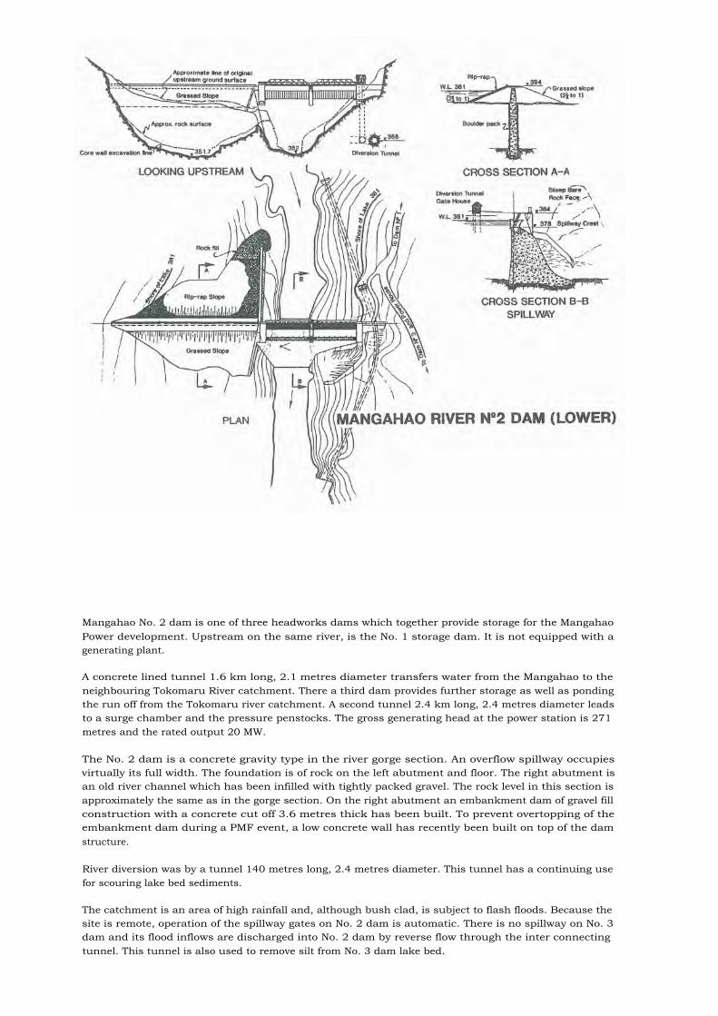
Mangahao No. 2 dam is one of three headworks dams which together provide storage for the MangahaoPower development. Upstream on the same river, is the No. 1 storage dam. It is not equipped with agenerating plant.
A concrete lined tunnel 1.6 km long, 2.1 metres diameter transfers water from the Mangahao to theneighbouring Tokomaru River catchment. There a third dam provides further storage as well as pondingthe run off from the Tokomaru river catchment. A second tunnel 2.4 km long, 2.4 metres diameter leadsto a surge chamber and the pressure penstocks. The gross generating head at the power station is 271metres and the rated output 20 MW.
The No. 2 dam is a concrete gravity type in the river gorge section. An overflow spillway occupiesvirtually its full width. The foundation is of rock on the left abutment and floor. The right abutment isan old river channel which has been infilled with tightly packed gravel. The rock level in this section isapproximately the same as in the gorge section. On the right abutment an embankment dam of gravel fillconstruction with a concrete cut off 3.6 metres thick has been built. To prevent overtopping of theembankment dam during a PMF event, a low concrete wall has recently been built on top of the damstructure.
River diversion was by a tunnel 140 metres long, 2.4 metres diameter. This tunnel has a continuing usefor scouring lake bed sediments.
The catchment is an area of high rainfall and, although bush clad, is subject to flash floods. Because thesite is remote, operation of the spillway gates on No. 2 dam is automatic. There is no spillway on No. 3dam and its flood inflows are discharged into No. 2 dam by reverse flow through the inter connectingtunnel. This tunnel is also used to remove silt from No. 3 dam lake bed.

28. Cobb Dam
Location or Map Refs NZMS 260 M26 397 995Nearest City NelsonRiver CobbPurpose Hydro Electric Power GenerationYears of construction 1949 - 1954Type and foundation Earthfill on talus and moraine foundationsHeight and crest length m 32.7 x 221Volume of dam cu metres x 1000 330Spillway type Inclined chutes discharging into culvertsSpillway gates 4 radial gates 6.1 m high x 5.2 m wideSpillway max. discharge capacity cumecs 950Reservoir capacity cu metres x 1000 28,000Owner Electricity Corporation of NZ LtdEngineering by Civil Works - Ministry of Works
Electrical - State Hydro-electric DepartmentConstruction by Civil Works - Ministry of Works
Electrical - State Hydro-electric Department

The dam is of zoned construction comprising:• The core is well graded gravel with a silt sand binder derived mainly from glacial moraine. The
maximum gravel size is 150 mm, the majority of particles are rounded. The design core section is awide one.
• The upstream shoulder of well graded gravel with a lower percentage of fines than for the corematerial. The source was a fairly stratified outwash fan of alluvial material. The maximum gravelsize is 150 mm.
• The downstream shoulder of well graded gravel of maximum size 300 mm. The source was a talusdeposit of poorly graded angular material.
Other dam sections are an internal drain (washed river gravel), downstream shoulder protection (wellgraded river gravel) and upstream shoulder protection (rip-rap from moranic boulders and quarriedquartzite). The dam materials were compacted by double drum sheepsfoot type rollers towed by heavytractors.
The foundation is predominantly magnesite with a band of serpentine on the right bank. Both rock typesare moderately fractured and are traversed by clay seams, some as thick as 150 mm. There is an apparentfault zone which appears to cross the left abutment obliquely and which was visible in the core trenchafter final excavation.
Overburden at the site varied in thickness from 3-15 metres. It comprised glacial, fluvio-glacial and talusdeposits. The rock foundation was grouted along the core centre line to provide a cut off. The damcentre line is not straight; a deviation in the downstream direction from the approximate centre of thedam to the right abutment utilised an earlier deep investigation excavation.
The diversion cut was located on the approximate dam centre line. It now forms one of the spillwayculvert sections. Part of the culvert is gated to provide a permanent dewatering facility.

29. Maitai Dam
Location or Map Refs NZMS 260 028 409 904Nearest City NelsonRiver Maitai (North Branch)Purpose Water supplyCatchment area sq km 13.5Years of construction 1984 - 1986Type and foundation Earth dam on rock/soil foundationHeight and crest length m 39 x 140Volume of dam cu metres x 1000 372Spillway type Service spillway - ungated ogee shaped crest
Auxiliary spillway - sandfill fuse plugSpillway max. discharge capacity cumecs 280Reservoir capacity cu metres x 1000 4000Reservoir area sq metres x 1000 320Owner Nelson City CouncilEngineering by Tonkin and Taylor Limited in association with
Worseldine and WellsConstruction by Wilkins and Davies Construction Company Limited
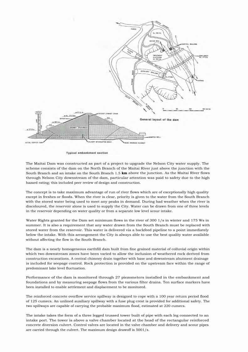
The Maitai Dam was constructed as part of a project to upgrade the Nelson City water supply. Thescheme consists of the dam on the North Branch of the Maitai River just above the junction with theSouth Branch and an intake on the South Branch 1.5 km above the junction. As the Maitai River flowsthrough Nelson City downstream of the dam, particular attention was paid to safety due to the highhazard rating; this included peer review of design and construction.
The concept is to take maximum advantage of run of river flows which are of exceptionally high qualityexcept in freshes or floods. When the river is clear, priority is given to the water from the South Branchwith the stored water being used to meet any peaks in demand. During bad weather when the river isdiscoloured, the reservoir alone is used to supply the City. Water can be drawn from one of three levelsin the reservoir depending on water quality or from a separate low level scour intake.
Water Rights granted for the Dam set minimum flows in the river of 300 1/s in winter and 175 Ws insummer. It is also a requirement that any water drawn from the South Branch must be replaced withstored water from the reservoir. This water is delivered via a backfeed pipeline to a point immediatelybelow the intake. With this arrangement the City is always able to use the best quality water availablewithout affecting the flow in the South Branch.
The dam is a nearly homogeneous earthfill dam built from fine grained material of colluvial origin withinwhich two downstream zones have been varied to allow the inclusion of weathered rock derived fromconstruction excavations. A central chimney drain together with base and downstream abutment drainageis included for seepage control. Rock protection is provided on the upstream face within the range ofpredominant lake level fluctuation.
Performance of the dam is monitored through 27 piezometers installed in the embankment andfoundations and by measuring seepage flows from the various filter drains. Ten surface markers havebeen installed to enable settlement and displacement to be monitored.
The reinforced concrete overflow service spillway is designed to cope with a 100 year return period floodof 125 cumecs. An unlined auxiliary spillway with a fuse plug crest is provided for additional safety. Thetwo spillways are capable of carrying the probable maximum flood, estimated at 220 cumecs.
The intake takes the form of a three legged trussed tower built of pipe with each leg connected to anintake port. The tower is above a valve chamber located at the head of the rectangular reinforcedconcrete diversion culvert. Control valves are located in the valve chamber and delivery and scour pipesare carried through the culvert. The maximum design drawoff is 5001/s.

30. Waihopai Dam
Location or Map Refs NZMS 260 029 575 490Nearest City Blenheim
River WaihopaiPurpose Hydro Electric Power Generation
Catchment area sq km 469
Year of construction 1926
Type and foundation Arch, Rock
Height and crest length m 35 x 56
Volume of dam cu metres x 1000 1.81Spillway type UncontrolledSpillway max. discharge capacity cumecs 700Reservoir capacity cu metres x 1000 zero - see Note (1)Reservoir area sq metres x 1000 zero - see Note (1)Owner Marlborough Electric Power BoardEngineering by Vickerman and LancasterConstruction by W Williamson
NOTE (1) In 1928 the total storage capacity including dead storage was 2420 thousand cu metres, by themid 1940's the reservoir was completely filled with river gravels and since that date the scheme has had nostorage. A syphon is used to keep the intake clear of gravel.
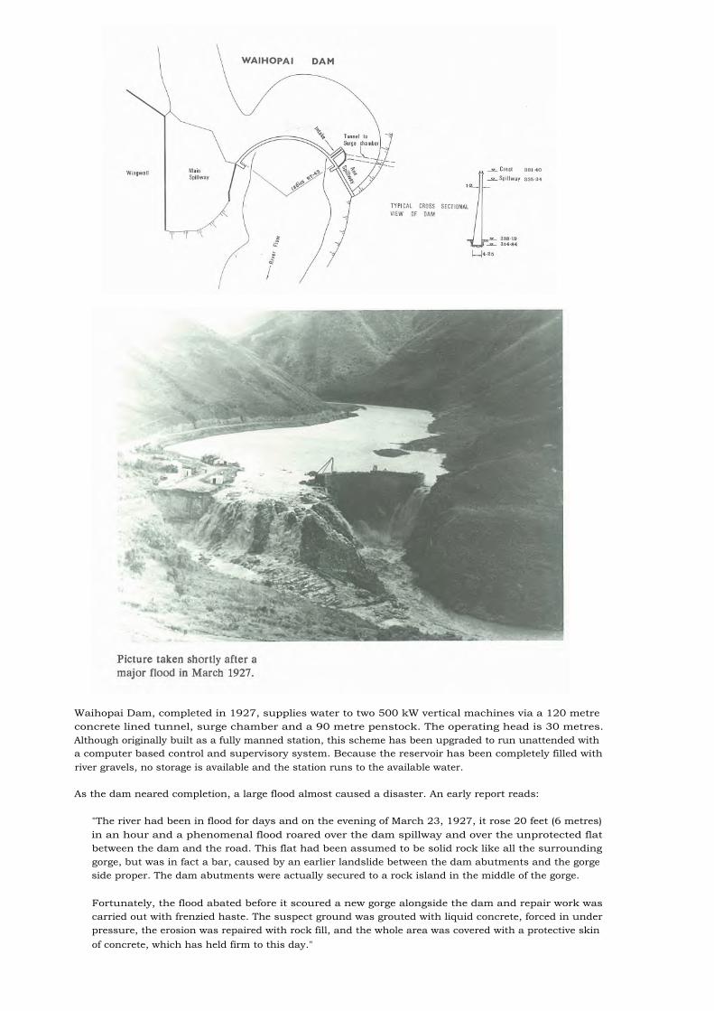
Waihopai Dam, completed in 1927, supplies water to two 500 kW vertical machines via a 120 metreconcrete lined tunnel, surge chamber and a 90 metre penstock. The operating head is 30 metres.Although originally built as a fully manned station, this scheme has been upgraded to run unattended witha computer based control and supervisory system. Because the reservoir has been completely filled withriver gravels, no storage is available and the station runs to the available water.
As the dam neared completion, a large flood almost caused a disaster. An early report reads:
"The river had been in flood for days and on the evening of March 23, 1927, it rose 20 feet (6 metres)in an hour and a phenomenal flood roared over the dam spillway and over the unprotected flatbetween the dam and the road. This flat had been assumed to be solid rock like all the surroundinggorge, but was in fact a bar, caused by an earlier landslide between the dam abutments and the gorgeside proper. The dam abutments were actually secured to a rock island in the middle of the gorge.
Fortunately, the flood abated before it scoured a new gorge alongside the dam and repair work wascarried out with frenzied haste. The suspect ground was grouted with liquid concrete, forced in underpressure, the erosion was repaired with rock fill, and the whole area was covered with a protective skinof concrete, which has held firm to this day."

31. Lake Argyle Dam
Location or Map Refs NZMS 260 N29 269 484Nearest City BlenheimRiver BranchPurpose Hydro generation, Irrigation, RecreationCatchment area sq km 770Years of construction 1982 - 1983Type and foundation Earth, SoilHeight and crest length m 15 x 1470Volume of dam cu metres x 1000 210Spillway type ControlledSpillway gates One, RadialSpillway max. discharge capacity cumecs See Note 1Reservoir capacity cu metres x 1000 1875Reservoir area sq metres x 1000 250Owner Marlborough Electric Power BoardEngineering by Royds Garden LtdConstruction by J McJorrow Ltd
NOTE (1): The Branch River Power Scheme is a diversion scheme, and water for generation is extractedfrom the river by a stream bed intake. The maximum diversion flow into Lake Argyle is 29 cumecs, andthe maximum flood discharge capacity of the intake weir is 2500 m3/sec.

The Lake Argyle Dam on the Branch River impounds water for the Branch power scheme. This schemedraws water from Lake Argyle and has two stations in series with 20 and 40 metres head respectively.The installed flow is 20 cumecs and the combined output is 11 MW. Lake Arglye, formed by the damhas, with no inflow, sufficient water for 8 hours generation at full load. The stations are automatic andrun unattended. A computer based supervisory system controls the generation scheduling and monitorsthe plant performance. The Lake Argyle Dam is also included in this monitoring system and keypiezometers and seepage are monitored on a 24 hour basis. The dam is founded on an alluvial terrace,400 metres upstream of the active Wairau fault. An accelerometer has been installed at the base of thedam which has been set to give an alarm for accelerations exceeding 0.1 g.
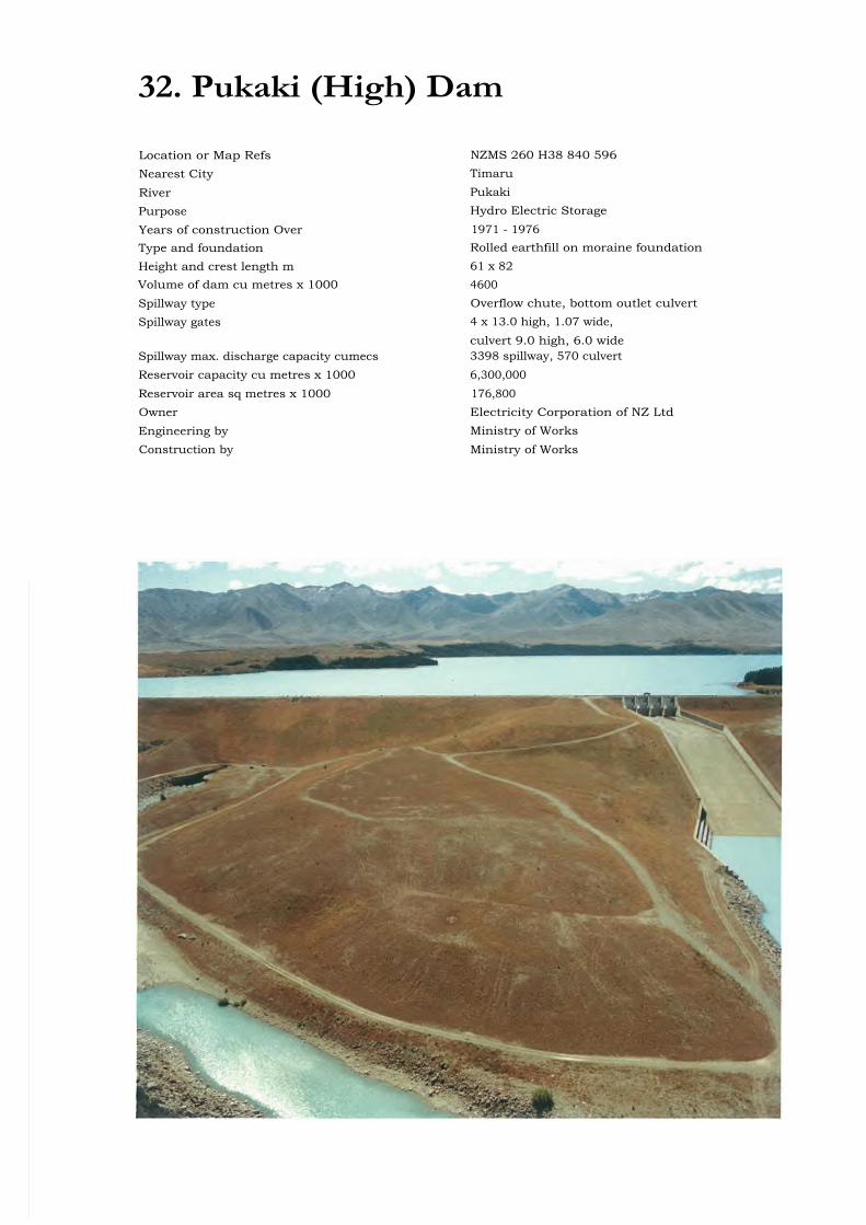
32. Pukaki (High) Dam
Location or Map Refs NZMS 260 H38 840 596Nearest City Timaru
River Pukaki
Purpose Hydro Electric Storage
Years of construction Over 1971 - 1976Type and foundation Rolled earthfill on moraine foundationHeight and crest length m 61 x 82Volume of dam cu metres x 1000 4600Spillway type Overflow chute, bottom outlet culvertSpillway gates 4 x 13.0 high, 1.07 wide,
culvert 9.0 high, 6.0 wideSpillway max. discharge capacity cumecs 3398 spillway, 570 culvertReservoir capacity cu metres x 1000 6,300,000Reservoir area sq metres x 1000 176,800Owner Electricity Corporation of NZ LtdEngineering by Ministry of WorksConstruction by Ministry of Works

The first Pukaki dam was commissioned in 1952 to provide storage for the Waitaki River hydrodevelopment. At that time Waitaki Station was in service and Benmore and other stations wereprojected. With development in the Upper Waitaki it became apparent that increased storage capacityshould be provided in the 1970s in order to achieve a higher utilisation of the available river discharges.
The new (high) dam is some 150 metres downstream of the original structure. The dam raised the levelof Lake Pukaki by a further 37 metres, inundating the low structure and doubling the lake's storagecapacity. The core of the new dam is connected to the core of the low dam to provide a long seepagepath.
Pukaki high dam is founded entirely on gravels, sands and silts of glacial origin, the site being slightlyupstream of the Tekapo terminal moraine loop at the southern end of Lake Pukaki. The deposits can bedivided into distinct geological units comprising two upper units of sand and silt and below them apredominantly gravel unit.
The main dam has upstream and downstream shoulders of outwash gravels, and a central core andupstream blanket of compacted silty gravels won from the terminal moraine. Transition zones ofprocessed material envelop the core and a downstream chimney drain intercepts all seepage flows throughthe structure. Protection against underseepage is provided by an extensive upstream blanket anddownstream relief wells.
Dam instrumentation comprises piezometers, groundwater observation wells, v-notch weirs, culvertsettlement markers and surface deformation markers. Four strong motion accelerators are installed.
The spillway is cut into the left abutment of the dam and a canal inlet structure is situated within aseparate saddle dam, some 300 metres west of the main dam.
The diversion culvert is an elliptical reinforced concrete structure, 10 metres high by 6 metres wide, whichextends for 360 metres adjacent to the right abutment of the dam.

33. Ruataniwha Dam
Location or Map Refs NZMS 260 H38 235 353Nearest City TimaruRiver OhauPurpose Hydro electricYears of construction 1978 - 1981Type and foundation Earthfill, RockHeight and crest length m Main dam 43 x 240 long,
wing dam 8 high x 480 longVolume of dam cu metres x 1000 800Spillway type Free overflow, gated sluiceSpillway gates Three radial 6.0 high, 9.0 wideSpillway max. discharge capacity cumecs 1,740Reservoir capacity cu metres x 1000 50,000Reservoir area sq metres x 1000 3,430Owner Electricity Corporation of NZ LtdEngineering by Ministry of Works and DevelopmentConstruction by Ministry of Works and Development
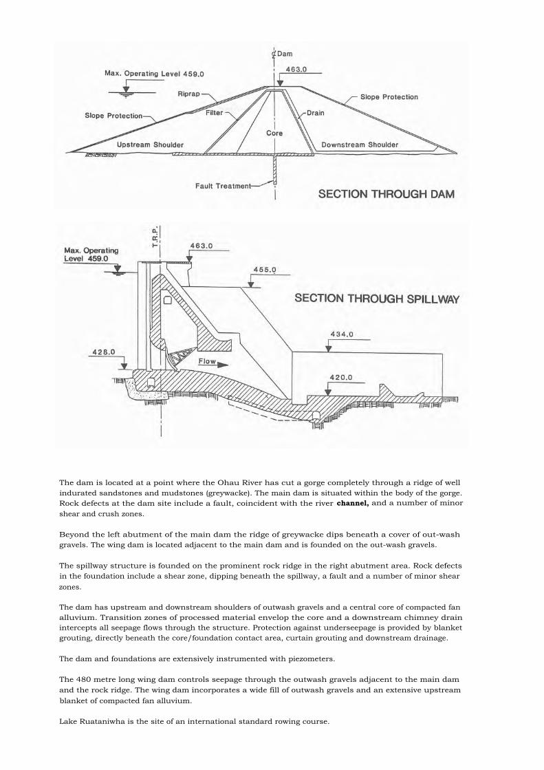
The dam is located at a point where the Ohau River has cut a gorge completely through a ridge of wellindurated sandstones and mudstones (greywacke). The main dam is situated within the body of the gorge.Rock defects at the dam site include a fault, coincident with the river channel, and a number of minorshear and crush zones.
Beyond the left abutment of the main dam the ridge of greywacke dips beneath a cover of out-washgravels. The wing dam is located adjacent to the main dam and is founded on the out-wash gravels.
The spillway structure is founded on the prominent rock ridge in the right abutment area. Rock defectsin the foundation include a shear zone, dipping beneath the spillway, a fault and a number of minor shearzones.
The dam has upstream and downstream shoulders of outwash gravels and a central core of compacted fanalluvium. Transition zones of processed material envelop the core and a downstream chimney drainintercepts all seepage flows through the structure. Protection against underseepage is provided by blanketgrouting, directly beneath the core/foundation contact area, curtain grouting and downstream drainage.
The dam and foundations are extensively instrumented with piezometers.
The 480 metre long wing dam controls seepage through the outwash gravels adjacent to the main damand the rock ridge. The wing dam incorporates a wide fill of outwash gravels and an extensive upstreamblanket of compacted fan alluvium.
Lake Ruataniwha is the site of an international standard rowing course.

34. Benmore Dam
Location or Map Refs NZMS 260 H39 280 164Nearest City TimaruRiver WaitakiPurpose Hydro ElectricCatchment area sq km 7,800Years of construction 1958 -1965Type and foundation Rolled fill dam on rock foundationHeight and crest length m 118 x 957Volume of dam cu metres x 1000 12,500Spillway type Gated overflow and sluice to chute spillwaySpillway gates 4 radial gates 11.9 high x 10.6 wide,
2 sluice gates 7.8 high x 6.1 wideSpillway max. discharge capacity cumecs 3,400Reservoir capacity cu metres x 1000 2,100,000Reservoir area sq metres x 1000 79,000Owner Electricity Corporation of NZ LtdEngineering by Civil Works - Ministry of Works,
Electrical Works - New Zealand ElectricityDepartment
Construction by Civil Works - Ministry of Works,Electrical Works - New Zealand Electricity
Department
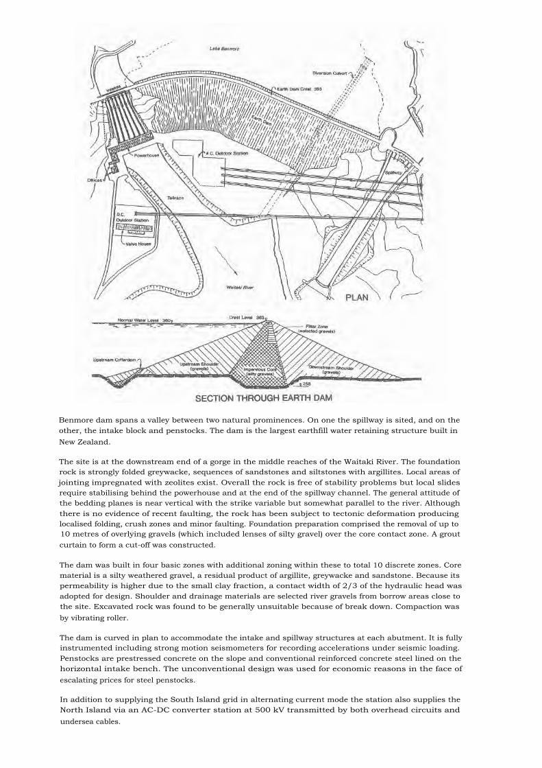
Benmore dam spans a valley between two natural prominences. On one the spillway is sited, and on theother, the intake block and penstocks. The dam is the largest earthfill water retaining structure built inNew Zealand.
The site is at the downstream end of a gorge in the middle reaches of the Waitaki River. The foundationrock is strongly folded greywacke, sequences of sandstones and siltstones with argillites. Local areas ofjointing impregnated with zeolites exist. Overall the rock is free of stability problems but local slidesrequire stabilising behind the powerhouse and at the end of the spillway channel. The general attitude ofthe bedding planes is near vertical with the strike variable but somewhat parallel to the river. Althoughthere is no evidence of recent faulting, the rock has been subject to tectonic deformation producinglocalised folding, crush zones and minor faulting. Foundation preparation comprised the removal of up to10 metres of overlying gravels (which included lenses of silty gravel) over the core contact zone. A groutcurtain to form a cut-off was constructed.
The dam was built in four basic zones with additional zoning within these to total 10 discrete zones. Corematerial is a silty weathered gravel, a residual product of argillite, greywacke and sandstone. Because itspermeability is higher due to the small clay fraction, a contact width of 2/3 of the hydraulic head wasadopted for design. Shoulder and drainage materials are selected river gravels from borrow areas close tothe site. Excavated rock was found to be generally unsuitable because of break down. Compaction wasby vibrating roller.
The dam is curved in plan to accommodate the intake and spillway structures at each abutment. It is fullyinstrumented including strong motion seismometers for recording accelerations under seismic loading.Penstocks are prestressed concrete on the slope and conventional reinforced concrete steel lined on thehorizontal intake bench. The unconventional design was used for economic reasons in the face ofescalating prices for steel penstocks.
In addition to supplying the South Island grid in alternating current mode the station also supplies theNorth Island via an AC-DC converter station at 500 kV transmitted by both overhead circuits andundersea cables.
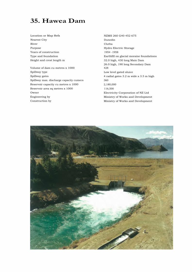
35. Hawea Dam
Location or Map Refs NZMS 260 G40 452 675Nearest City DunedinRiver CluthaPurpose Hydro Electric StorageYears of construction 1954 -1958Type and foundation Earthfill on glacial moraine foundationsHeight and crest length m 32.0 high, 430 long Main Dam
26.0 high, 190 long Secondary DamVolume of dam cu metres x 1000 428Spillway type Low level gated sluiceSpillway gates 4 radial gates 3.2 m wide x 3.5 m highSpillway max. discharge capacity cumecs 360Reservoir capacity cu metres x 1000 2,180,000Reservoir area sq metres x 1000 116,500Owner Electricity Corporation of NZ LtdEngineering by Ministry of Works and DevelopmentConstruction by Ministry of Works and Development
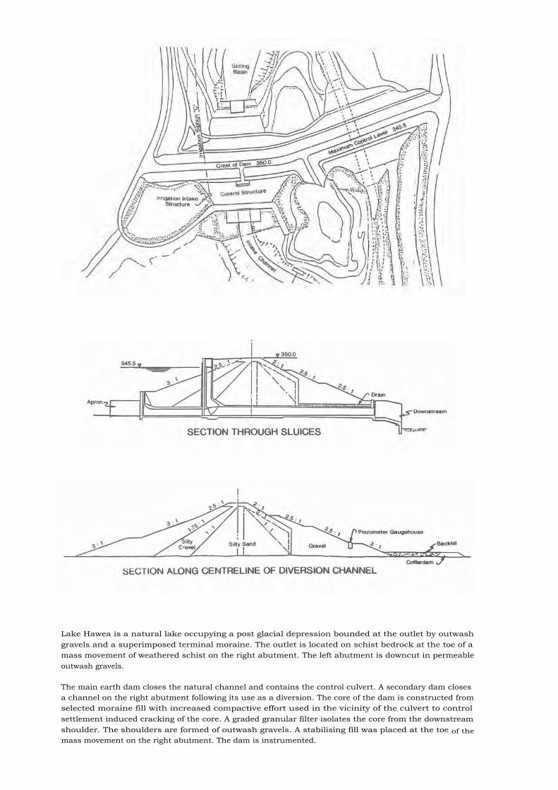
Lake Hawea is a natural lake occupying a post glacial depression bounded at the outlet by outwashgravels and a superimposed terminal moraine. The outlet is located on schist bedrock at the toe of amass movement of weathered schist on the right abutment. The left abutment is downcut in permeableoutwash gravels.
The main earth dam closes the natural channel and contains the control culvert. A secondary dam closesa channel on the right abutment following its use as a diversion. The core of the dam is constructed fromselected moraine fill with increased compactive effort used in the vicinity of the culvert to controlsettlement induced cracking of the core. A graded granular filter isolates the core from the downstreamshoulder. The shoulders are formed of outwash gravels. A stabilising fill was placed at the toe of themass movement on the right abutment. The dam is instrumented.
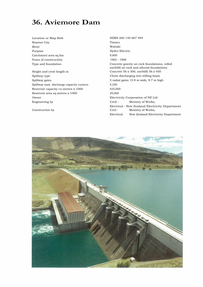
36. Aviemore Dam
Location or Map Refs NZMS 260 140 867 494
Nearest City TimaruRiver WaitakiPurpose Hydro ElectricCatchment area sq km 9,600Years of construction 1962 - 1968Type and foundation Concrete gravity on rock foundations, rolled
earthfill on rock and alluvial foundationsHeight and crest length m Concrete 56 x 300, earthfill 56 x 450Spillway type Chute discharging into stilling basinSpillway gates 5 radial gates 15.9 m wide, 9.7 m highSpillway max. discharge capacity cumecs 4,250Reservoir capacity cu metres x 1000 425,000Reservoir area sq metres x 1000 29,000Owner Electricity Corporation of NZ LtdEngineering by Civil - Ministry of Works,
Electrical - New Zealand Electricity DepartmentConstruction by Civil - Ministry of Works,
Electrical New Zealand Electricity Department

A geological feature, a fault line which crosses the site at an angle to the dam axis, dictated the layout ofthe structures. On the upthrust (left bank) side of the fault, greywacke, which is partially shattered andhas argillite inclusions, lies close to the surface and was covered by a comparatively thin layer of rivergravels. This rock was a suitable foundation for the construction of the concrete dam section (whichincorporates the intakes, powerhouse, spillway and sluices).
On the downthrust (right bank) side of the fault, there is some 200 metres depth of tertiary clays, silts andsteeply dipping coal seams overlaid by river gravels. The earth dam was built on this foundation. Theearth dam is founded on rock for a short length from the earth/concrete dam interface.
The concrete dam was designed as a conventional gravity type structure and was built in 18 metres widebays with keyed waterstopped joints. Diversion was by a left bank tunnel 520 metres long. Dam concretemix design incorporated a low heat modified cement at the rate of 105 kgm/cubic metre. There was noartificial cooling. Drainage and grout curtains were drilled from galleries within the dam.Instrumentation comprised foundation piezometers, drain flow weirs, levelling pins and optical plummets.Regular deformation surveys are carried out.
The earth dam was constructed in 7 zones comprising a wide core of impervious silty clay, a downstreamsand gravel transition and upstream and downstream gravel/rock shoulders. There is a large section graveldrainage zone running the full length of the dam. There are two further zones of rock for upstreamshoulder protection. On the centre-right bank length of the dam the core is founded on a lowpermeability clay/silt. Dam instrumentation includes piezometers in the core and foundation zones,settlement cells and deformation pillars.
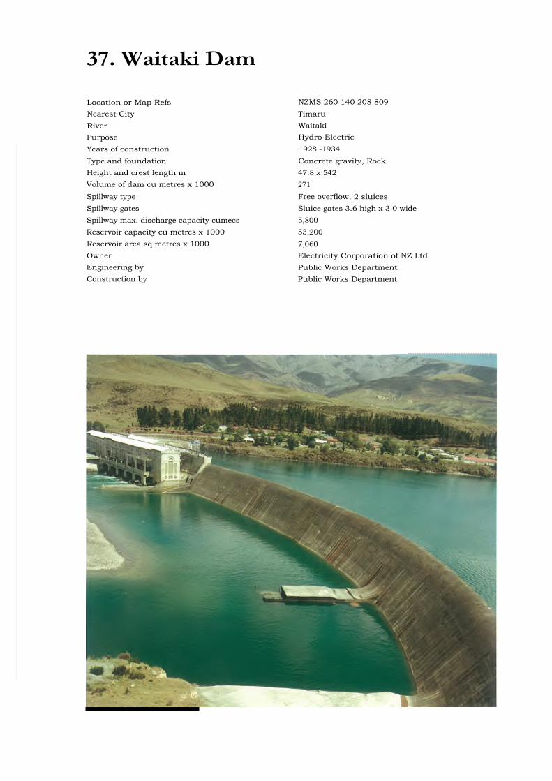
37. Waitaki Dam
Location or Map Refs NZMS 260 140 208 809Nearest City TimaruRiver WaitakiPurpose Hydro ElectricYears of construction 1928 -1934Type and foundation Concrete gravity, RockHeight and crest length m 47.8 x 542Volume of dam cu metres x 1000 271Spillway type Free overflow, 2 sluicesSpillway gates Sluice gates 3.6 high x 3.0 wideSpillway max. discharge capacity cumecs 5,800Reservoir capacity cu metres x 1000 53,200Reservoir area sq metres x 1000 7,060Owner Electricity Corporation of NZ LtdEngineering by Public Works DepartmentConstruction by Public Works Department
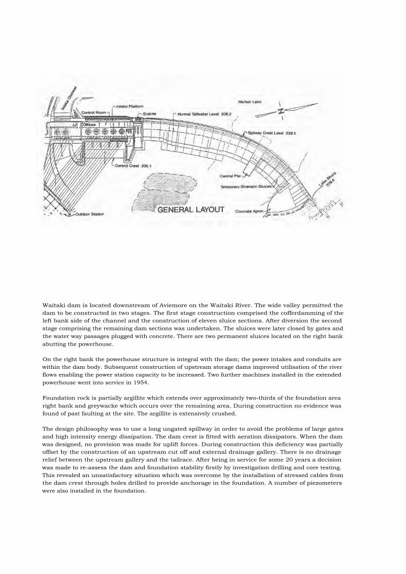
Waitaki dam is located downstream of Aviemore on the Waitaki River. The wide valley permitted thedam to be constructed in two stages. The first stage construction comprised the cofferdamming of theleft bank side of the channel and the construction of eleven sluice sections. After diversion the secondstage comprising the remaining dam sections was undertaken. The sluices were later closed by gates andthe water way passages plugged with concrete. There are two permanent sluices located on the right bankabutting the powerhouse.
On the right bank the powerhouse structure is integral with the dam; the power intakes and conduits arewithin the dam body. Subsequent construction of upstream storage dams improved utilisation of the riverflows enabling the power station capacity to be increased. Two further machines installed in the extendedpowerhouse went into service in 1954.
Foundation rock is partially argillite which extends over approximately two-thirds of the foundation arearight bank and greywacke which occurs over the remaining area. During construction no evidence wasfound of past faulting at the site. The argillite is extensively crushed.
The design philosophy was to use a long ungated spillway in order to avoid the problems of large gatesand high intensity energy dissipation. The dam crest is fitted with aeration dissipators. When the damwas designed, no provision was made for uplift forces. During construction this deficiency was partiallyoffset by the construction of an upstream cut off and external drainage gallery. There is no drainagerelief between the upstream gallery and the tailrace. After being in service for some 20 years a decisionwas made to re-assess the dam and foundation stability firstly by investigation drilling and core testing.This revealed an unsatisfactory situation which was overcome by the installation of stressed cables fromthe dam crest through holes drilled to provide anchorage in the foundation. A number of piezometerswere also installed in the foundation.

38. Clyde Dam
Location or Map Refs NZMS 260 G42 236 948Nearest City DunedinRiver CluthaPurpose Hydro ElectricYears of construction 1980 - 1989Type and foundation Concrete gravity on schist rockHeight and crest length m 102 x 490Volume of dam cu metres x 1000 1,000Spillway type Chute and sluice with stilling basinSpillway gates Radial - spillway 4 gates 14.3 high, 10.0 wide -
Sluice 1 gate 9.0 high, 6.0 wideSpillway max. discharge capacity cumecs Spillway 4,100, sluice 1,400Reservoir capacity cu metres x 1000 350,000Reservoir area sq metres x 1000 25,000Owner Electricity Corporation of NZ LtdEngineering by Civil - Ministry of Works and Development
Electrical - Electricity Division of Ministry ofEnergy
Construction by Civil - Zublin-Williamson Joint Venture Ministryof Works and DevelopmentElectrical - Electricity Division of Ministry ofEnergy

A major feature of the site is a fault in the river channel with gouge or crush zones up to 8 metres wide inplaces. Several other faults of more than 1 metre also cross the damsite.
The schist foundation rock at the damsite contains frequent foliation shears. Two persistent shearsextending from the right abutment towards the centre of the dam were treated by excavating a series ofadits and backfilling them with concrete to act as shear keys. The foundation in other areas has beendeepened to found the dam below shear surfaces.
The concrete dam contains 1 million cu metres of concrete in 28 blocks varying in width from 12.5 metresto 21 metres. Intakes have been included in the diversion dam blocks to allow for future installation oftwo additional generating units within the existing river diversion channel when required. A 1.8 metrediameter irrigation offtake is located on the right abutment. A single row grout curtain was drilled froman upstream gallery in the dam, with drain holes drilled downstream of the grout curtain.
A slip joint has been provided in the dam to allow up to 2 metre movement on the plane of the riverchannel fault passing through the dam foundation. To keep the joint watertight under normal operationand to limit flow in the event of fault displacement, a 100 metre high concrete wedge plug lined withstainless steel plate is located at the upstream face of the dam.
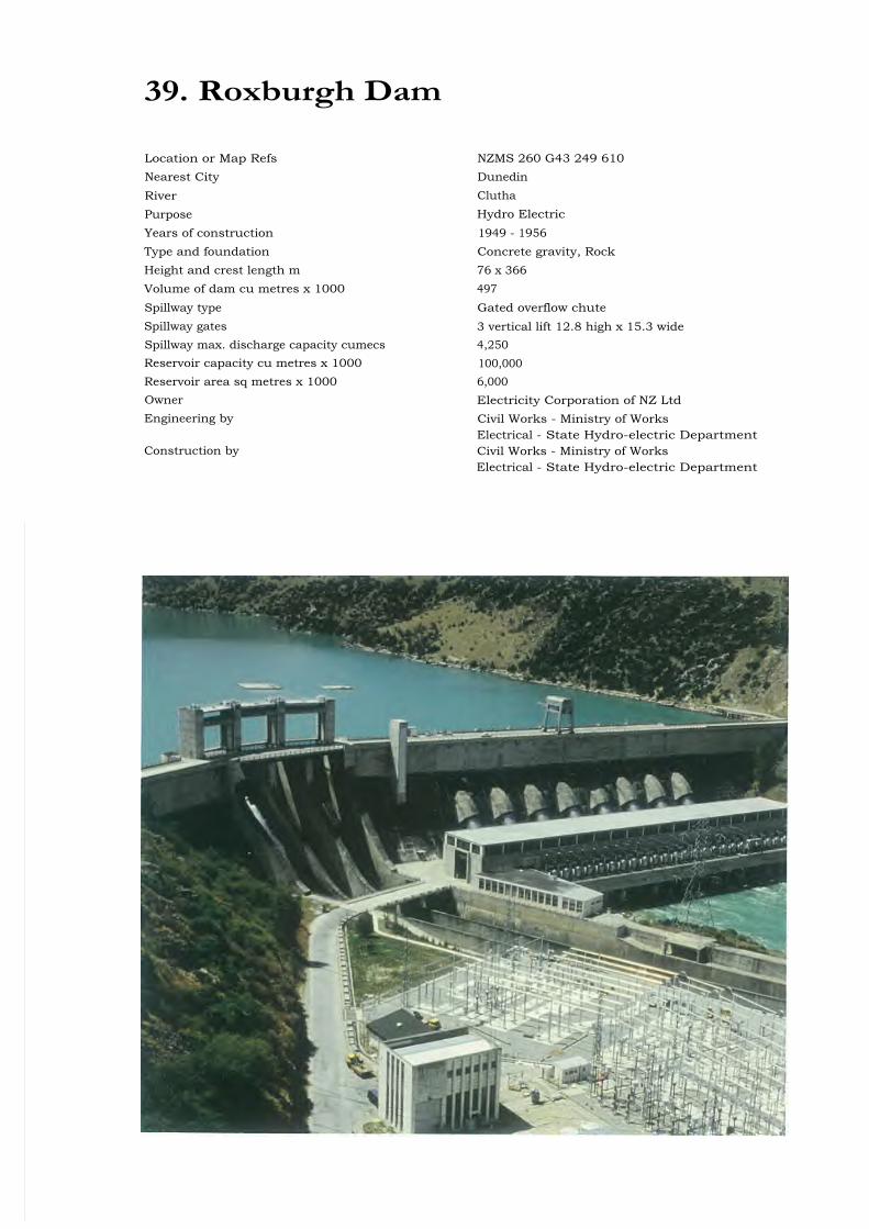
39. Roxburgh Dam
Location or Map Refs NZMS 260 G43 249 610Nearest City DunedinRiver CluthaPurpose Hydro ElectricYears of construction 1949 - 1956Type and foundation Concrete gravity, RockHeight and crest length m 76 x 366Volume of dam cu metres x 1000 497Spillway type Gated overflow chuteSpillway gates 3 vertical lift 12.8 high x 15.3 wideSpillway max. discharge capacity cumecs 4,250Reservoir capacity cu metres x 1000 100,000Reservoir area sq metres x 1000 6,000Owner Electricity Corporation of NZ LtdEngineering by Civil Works - Ministry of Works
Electrical - State Hydro-electric DepartmentConstruction by Civil Works - Ministry of Works
Electrical - State Hydro-electric Department
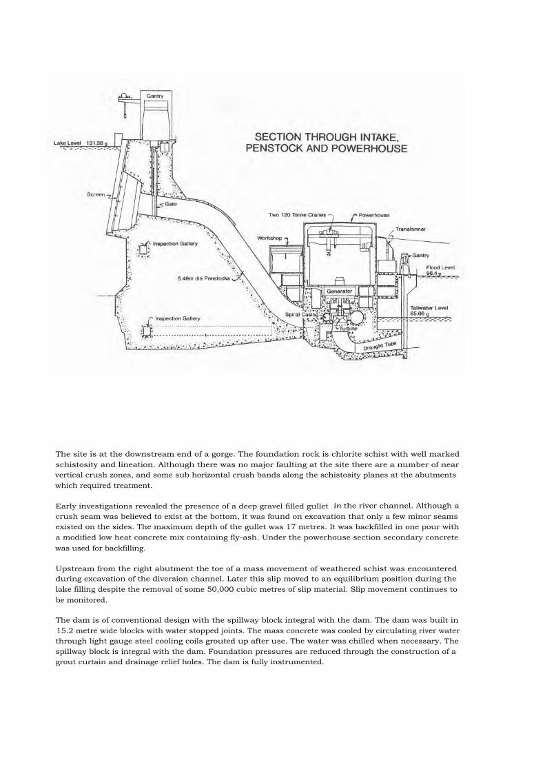
The site is at the downstream end of a gorge. The foundation rock is chlorite schist with well markedschistosity and lineation. Although there was no major faulting at the site there are a number of nearvertical crush zones, and some sub horizontal crush bands along the schistosity planes at the abutmentswhich required treatment.
Early investigations revealed the presence of a deep gravel filled gullet in the river channel. Although acrush seam was believed to exist at the bottom, it was found on excavation that only a few minor seamsexisted on the sides. The maximum depth of the gullet was 17 metres. It was backfilled in one pour witha modified low heat concrete mix containing fly-ash. Under the powerhouse section secondary concretewas used for backfilling.
Upstream from the right abutment the toe of a mass movement of weathered schist was encounteredduring excavation of the diversion channel. Later this slip moved to an equilibrium position during thelake filling despite the removal of some 50,000 cubic metres of slip material. Slip movement continues tobe monitored.
The dam is of conventional design with the spillway block integral with the dam. The dam was built in15.2 metre wide blocks with water stopped joints. The mass concrete was cooled by circulating river waterthrough light gauge steel cooling coils grouted up after use. The water was chilled when necessary. Thespillway block is integral with the dam. Foundation pressures are reduced through the construction of agrout curtain and drainage relief holes. The dam is fully instrumented.
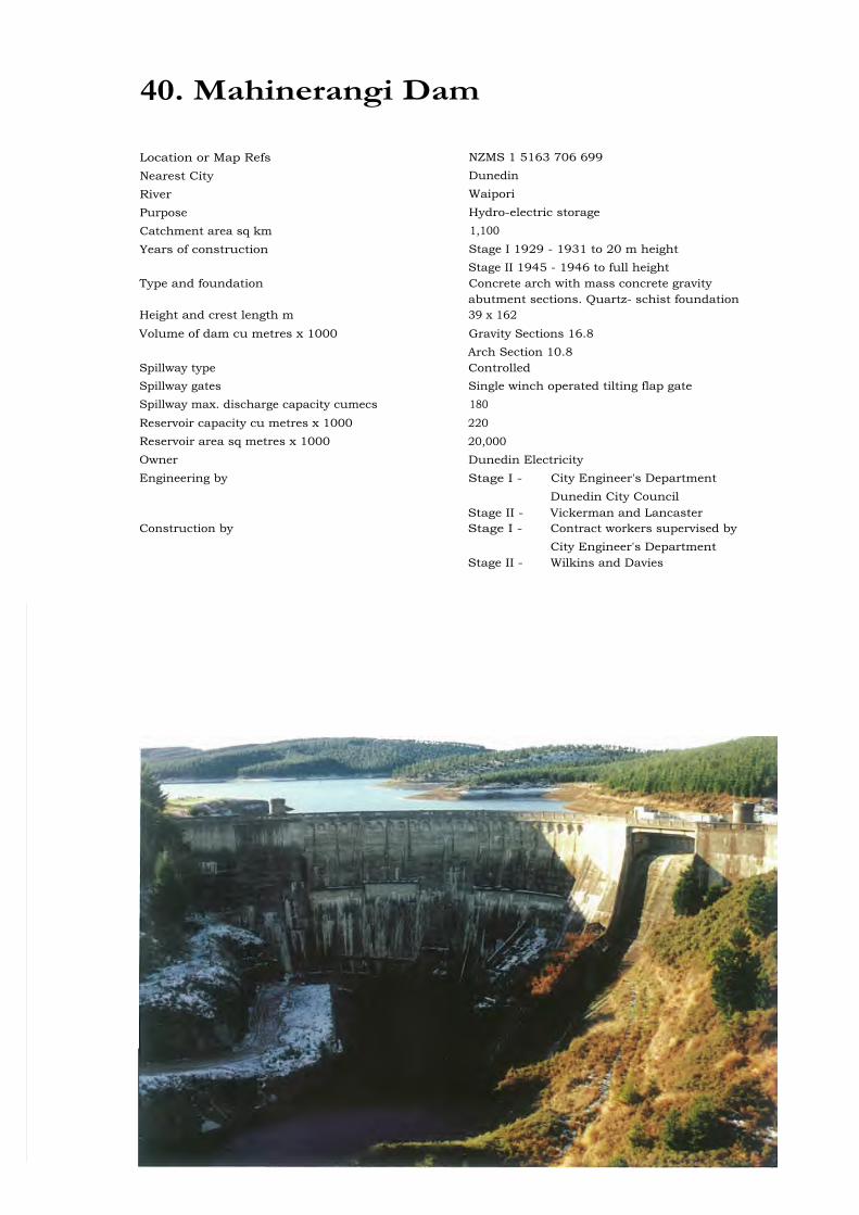
40. Mahinerangi Dam
Location or Map Refs NZMS 1 5163 706 699Nearest City DunedinRiver WaiporiPurpose Hydro-electric storageCatchment area sq km 1,100Years of construction Stage I 1929 - 1931 to 20 m height
Stage II 1945 - 1946 to full heightType and foundation Concrete arch with mass concrete gravity
abutment sections. Quartz- schist foundationHeight and crest length m 39 x 162Volume of dam cu metres x 1000 Gravity Sections 16.8
Arch Section 10.8Spillway type ControlledSpillway gates Single winch operated tilting flap gateSpillway max. discharge capacity cumecs 180Reservoir capacity cu metres x 1000 220Reservoir area sq metres x 1000 20,000Owner Dunedin ElectricityEngineering by Stage I - City Engineer's Department
Dunedin City CouncilStage II - Vickerman and Lancaster
Construction by Stage I - Contract workers supervised byCity Engineer's Department
Stage II - Wilkins and Davies

The site of the Mahinerangi Reservoir is a down-warped basin in an ancient plateau through the risingedge of which the Waipori River escapes into a narrow gorge. The dam itself is founded on Otago schistformation but locally the rock differs from the prevailing quartz-mica schist in the amount of hornblende,epidote and chlorite, green silicate material. Felspar, mica, graphite and some pyrites are also found in therock.
The dam comprises a constant radius arch section approximately 40 metres maximum height, having aradius of 48.8 metres and a central angle of 72°, and is flanked by two gravity sections. In each gravitysection a drainage system is provided to discharge into a small longitudinal gallery approximately 1.50metres high and 0.75 metres wide. Drains formed by thin galvanised iron tubes with loose joints at about1.50 metres centres extend upwards and downwards from the galleries at approximately 2.10 metresintervals. The tubes extending downwards connect with a porous concrete drain which runs longitudinallyalong the base of the dam, into the lower end of each gallery. The radial joints in the arch and thetransverse joints in the gravity abutments were painted with bitumen and were provided with copper waterstops and 0.3 metres x 1.2 metres square faced shear keys. There is a concrete cut-off wall of variousdepths under the full length of the dam. Grout holes spaced at 1.5 metres and staggered in two rowsapproximately 1 metre apart and 6 metres deep were drilled beneath the cut-off wall and grouted.
The arch was designed as a thick cylinder without allowance for cantilever action, elastic deformations,joint opening and temperature effects. The gravity sections were designed on the assumption that thedrainage system would prevent development of any hydraulic uplift or seepage forces. The effect ofearthquake was not considered in the design. The left hand gravity section was designed with a 13.7metre wide spillway, and with an automatic counter weighted tilting flap gate. The counter weightoperating system was subsequently decommissioned and replaced by a manually operated single electricwinch control.
In 1985 the original power station erected at the foot of the dam was demolished and supply conduitthrough the dam to the station plugged.
In 1960 structural stability calculations indicated additional vertical loading was required in the gravityabutments to provide stability for the dam under seismic loading conditions. This was achieved byproviding a total of 20 x 290 tonne cables, spaced to meet the requirement of approximately 6,000 tonnesof prestress required. Cable holes of 100 mm diameter were drilled straight and vertical through the damroadway and carried into bedrock for a sufficient distance to pick up the required rock mass andanchorage length. In association with the anchor stressing new 75 mm diameter pressure relief holes weredrilled to intersect the existing internal galleries.

Glossary of Terms
Andesite : a volcanic rock
Argillite : a sedimentary rock
Basalt : a volcanic rock
Colluvial : material accumulating on a slope from weathering and erosion processes
Cretaceo-tertiary : a geological period 60-70 million years ago
Greywacke : a sedimentary rock
Ignumbrite : a volcanic rock
Jurassic age : geological period 145 to 210 million years ago
Lahar : landslide or mudflow originating from a volcano
Magnesite : a carbonate mineral
Miocene : a geological period 6 to 22 million years ago
Moraine : deposits of rock and soil materials transported and deposited by glacier on
meltwater streams
Piezometer : an instrument for measuring water pressure
Pyroclastic : materials that have been ejected from a volcanic vent
Rhyolite : a volcanic rock
Schist : a metamorphic rock
Serpentine : a mineral
Talus : a collection of fallen rock material which forms at the foot of a steep slope
Tertiary age : a geological period 2 to 65 million years ago