Embed Size (px)
Citation preview
Department
Of
Mechanical
Engineering
Improved Performance of Bio-lubricant
By Nanoparticles Additives
Julius Oluwatayo Abere
April 2017
Thesis submitted for the degree of Doctor of Philosophy
1

2
Abstract
Nanoparticle additives are proposed to improve lubricant performance under boundary
lubrication sliding, through tribofilms formation. Tribofilms consisting of the elements of the
nanoparticles (NPs) could form on the sliding surface providing necessary FM and reduction
in wear volume loss. The key aim of this thesis is to establish a proof-of-concept for the
Polyvit NPs lubricant additives a biolubricant – rapeseed oil. The improvement potentials
may either complement or replace (partially or fully) some existing additives. Lubricants and
their additives are being reviewed for better alternatives regarding toxicity, biodegradability
and environmental issues.
The Polyvit NPs consist of alumina (Al2O3), silica (SiO2) and graphite (C); although the TEM
analysis shows silica only. The NPs were mixed at 0.1 wt. % with raw rapeseed oil and a
fully formulated mineral oil - SAE15W-40. Initial tribotesting suggest possible combination
of the NPs with the AW additive – zinc dialkyldithiophosphate (ZDDP). This was tested
experimentally on both the Plint TE 77 ball-on-flat and the Bruker UMT tribometers. Both
the HFRR and UMT tests are conducted in the boundary lubrication regime at RT and 100oC
respectively. The fully flooded approach is adopted with a contact load of 40 N, while the
starved lubrication approach is adopted for HFRR and UMT tests under a load of 5 N.
Surface chemical analyses on the SEM/EDX show the presence of the elements of the NPs
and ZDDP on sliding wear tracks. Thus, boundary lubrication tribofilm of the NPs form on
the wear track. Also, the presence of ZDDP enhances formation of tribofilm of both the NPs
and ZDDP on the sliding wear track at RT. Addition of the Polyvit NPs and ZDDP reduce
wear at RT for the biolubricant. Also, the mineral oil lubricant can have friction and wear
improvements through the addition of the NPs at low and high temperature boundary
lubrication sliding.
3
Acknowledgements
My sincere gratitude to the Federal Government of Nigeria for sponsorship of the PhD
through the Tertiary Education Trust Fund (TETFund), under TETFund AST & DI, 2012.
Thanks to the Vice-Chancellor and Management of Ekiti State University (EKSU), Ado-
Ekiti, for the Full-Time Study Leave over the period of study. Equally, I appreciate the Dean
of Engineering, the Head of Dept. (Mechanical Engineering) and the staff and students of
Engineering EKSU for understanding, support and help as necessary.
My supervisors – Dr. Tom Slatter and Prof. Roger Lewis – are very supportive; they provided
guidance and foresight throughout the study. Thanks to Phil Metcalfe of Efficiency
Technologies, UK for supply of the Polyvit NPs. Thanks to Millers Oil UK for the ZDDP
additives. The Biolubricant cluster: Adli, Julia, Nopparat and Lawal; thank you. I appreciate
fellow UMT users: Ben, Marcello, Kei and others; thank you. Thanks to Dave Butcher and
other lab staff for help with equipment at the TriboTech, Leonardo and Microprep Labs. Flat
samples and UMT discs are machined and made available by the Mechanical Engineering
Workshop. Thanks, Richard at Lea Lab, for the Vicker’s hardness machine. Everyone along
the learning way is helpful. Thank you.
This PhD story would be incomplete without the good works of brethren in Foursquare
Gospel Church, City of Refuge, Sheffield. Pastor Abi provided leadership while brethren
gracefully supported me and my family. I am very grateful to Ebenezer Oluwabori07 and his
family for unparalleled support. They stood with me throughout the study. Thank you, dear
brethren in the Choir and Prudence Group UK. Brethren, you are highly valuable, important
and amazing (2 Corinthians 15:58 NCV).
Thanks to EKSU, Nigerian and African scholars in Sheffield for the laughs and helps. My family shared with me the pains of absence and travel. They are supportive, especially
during this study and related experience. Special thanks to my darling Mojisola and our sons:
JesulOba, MoyinOluwa, Jesupemi and Oluwaga. I express sincere gratitude and warm
regards to all of Abere and Duyile families, relations and friends; thank you.
4
Contents
Abstract......................................................................................................................................3
Acknowledgements....................................................................................................................4
Contents......................................................................................................................................5
1 Introduction.......................................................................................................................11
1.2 General Background..................................................................................................11
1.3 Statement of the Problem..........................................................................................16
1.4 Aim of the Research..................................................................................................16
1.5 Objectives and Scope of the Work............................................................................16
1.5.1 Objectives of the research..................................................................................17
1.5.2 Scope of Work....................................................................................................17
1.6 Outline of the Dissertation.........................................................................................17
2 Base Oils, Additives and Lubricant Formulation.............................................................19
2.1 Introduction...............................................................................................................19
2.2 Properties of Lubricating oils....................................................................................20
2.2.1 Physical Properties of Lubricants.......................................................................20
2.2.1.1 Viscosity.....................................................................................................21
2.2.1.2 Viscosity Index...........................................................................................23
2.2.1.3 Lubricant Viscosity Classification..............................................................24
2.2.1.4 Density and Specific Gravity......................................................................25
2.2.2 Thermal Properties of Lubricants.......................................................................25
2.2.3 Temperature Characteristics of Lubricants........................................................26
2.2.3.1 Pour Point and Cloud Point........................................................................26
2.2.3.2 Flash Point and Fire Point...........................................................................26
2.2.3.3 Volatility and Evaporation..........................................................................27
2.2.3.4 Oxidation Stability......................................................................................27
5
2.2.3.5 Thermal Stability........................................................................................27
2.2.3.6 Element Content.........................................................................................28
2.2.4 Additive Compatibility and Solubility in Lubricants.........................................28
2.3 Lubricant Base Oils...................................................................................................29
2.4 Biolubricant as Alternative to Mineral (base) Oil.....................................................31
2.5 Engine Lubricant Additives.......................................................................................33
2.5.1 Surface Protection Additives..............................................................................34
2.5.1.1 FMs.............................................................................................................34
2.5.1.2 AW Additives.............................................................................................36
2.5.1.3 Extreme Pressure Additives........................................................................38
2.5.2 Interaction between Additives............................................................................39
2.6 Formulation of Automotive Engine Lubricants........................................................40
2.7 Conclusions...............................................................................................................42
3 Tribology and Tribotesting in Boundary Lubrication Regime.........................................44
3.1 Tribology...................................................................................................................44
3.2 The Surface in Tribology...........................................................................................46
3.2.1 Surface Characterisation....................................................................................47
3.3 Friction......................................................................................................................48
3.4 Boundary Lubrication................................................................................................51
3.4.1 Theory of Boundary Lubrication.......................................................................52
3.4.2 Categories of Boundary Lubrication..................................................................53
3.4.2.1 Low Temperature-Low Load Boundary Lubrication Mechanisms............54
3.4.2.2 Low Temperature-High Load Boundary Lubrication Mechanisms...........54
3.4.2.3 High Temperature-Medium Load Lubrication Mechanisms......................58
3.4.2.4 High Temperature-High Load Lubrication Mechanisms............................59
3.4.3 Mechanisms of Boundary Lubricating films......................................................60
3.4.4 Tribotest Methods in Boundary Lubrication......................................................61
6
3.4.4.1 The Ball-on-flat HFRR Tribometer............................................................62
3.4.4.2 The Pin-on-disc tribometer.........................................................................63
3.5 Wear..........................................................................................................................64
3.5.1 Wear Mechanisms in Sliding.............................................................................65
3.5.1.1 Running-in..................................................................................................67
3.5.1.2 Adhesive Wear............................................................................................67
3.5.1.3 Abrasive Wear............................................................................................68
3.5.1.4 Delamination Wear.....................................................................................69
3.6 Lubrication................................................................................................................69
3.6.1 Lubrication Regimes: Stribeck Curve and Lambda Parameter..........................70
3.7 Boundary Lubrication of the Piston Ring-Cylinder Liner Contact...........................73
3.8 Conclusions...............................................................................................................77
4 NPs Lubricant Additives...................................................................................................79
4.2 Properties of NPs in Tribology..................................................................................79
4.3 Lubrication Mechanisms of NPs in Lubricants.........................................................80
4.4 NPs Additives – Some Earlier Works.......................................................................83
4.4.1 NPs Additives in Mineral Oil.............................................................................84
4.4.2 NPs Additives in Poly alpha olefin (PAO)........................................................86
4.4.3 NPs Additives in Rapeseed Oil..........................................................................88
4.5 NPs Additives and the Polyvit...................................................................................88
4.5.1 Nano-alumina Particles Additives......................................................................88
4.5.2 Silica and Silicate NPs Additives.......................................................................89
4.5.3 Graphite NPs Additives......................................................................................90
4.5.4 Composites of Any Two of Alumina, Silica and Graphite NPs........................91
4.6 The Polyvit NPs Additive..........................................................................................92
4.7 Conclusions...............................................................................................................93
5 Ball-on-flat Test of the Lubricants and NPs under Load, 40 N........................................95
7
5.1 The Ball-on-flat Reciprocating Sliding (HFRR) Tribotest........................................95
5.2 Materials....................................................................................................................96
5.2.1 The ball and flat samples....................................................................................96
5.2.2 The Lubricants: Rapeseed Oil and Mineral Oil.................................................98
5.2.3 The Polyvit NPs.................................................................................................99
5.3 The Ball-on-flat Test Conditions...............................................................................99
5.3.1 Contact Pressure Calculation...........................................................................100
5.3.2 Minimum Film Thickness and Lambda Ratio Analysis..................................103
5.3.2.1 Minimum film thickness...........................................................................103
5.3.2.2 The Lambda Ratio Analysis.....................................................................105
5.3.3 Test Conditions with Load of 40 N..................................................................106
5.3.4 Specimen code, Temperature, Lubricants and Test Program..........................107
5.4 Analytical Tools......................................................................................................108
5.4.1 Characterisation of the NPs..............................................................................108
5.5 Friction Behaviour of the Lubricants......................................................................109
5.6 Wear Behaviour of the Lubricants..........................................................................113
5.7 Effects of Non-homogenous Hardness of Flat Samples on Wear...........................114
5.8 Wear Scar Morphological Examination..................................................................116
5.8.1 Wear Mechanisms on the Flat Sample.............................................................118
5.8.2 Wear Mechanisms on the Ball Sample............................................................120
5.9 SEM/EDX Chemical Analysis of Wear Surface.....................................................122
5.10 Conclusions.............................................................................................................124
6 HFRR Tests with the Lubricants under a Load of 5 N...................................................125
6.1 The Ball-on-flat Test under a Load of 5 N..............................................................125
6.2 Test Materials..........................................................................................................126
6.2.1 The Ball and Flat Samples...............................................................................126
6.2.2 The Lubricants.................................................................................................126
8
6.3 Spectrochemical Analyses of the Lubricants..........................................................127
6.4 Test Methods...........................................................................................................128
6.4.1 General Test Conditions...................................................................................128
6.4.2 Surface Preparation and Cleaning....................................................................129
6.4.3 The Test Procedure..........................................................................................130
6.5 Results from Tribotests under the Load of 5 N.......................................................131
6.5.1 Coefficient of Friction......................................................................................131
6.5.2 Results: WSW (WSW).....................................................................................134
6.5.3 Wear Scar Profile and 3D Image.....................................................................135
6.6 Wear Surface Chemical Analysis............................................................................139
6.7 Conclusions.............................................................................................................143
7 The Pin-on-Disc Unidirectional Sliding Test.................................................................145
7.1 The Pin-on-disc Test................................................................................................145
7.2 Materials and Test Conditions.................................................................................146
7.2.1 The Ball and Disc Samples..............................................................................146
7.2.2 The Lubricants.................................................................................................146
7.2.3 The Pin-on-disc Test Conditions......................................................................147
7.3 Results and Discussion: Pin-on-disc Tribotest........................................................148
7.3.1 Coefficient of Friction......................................................................................148
7.3.2 Wear Rate Analysis..........................................................................................151
7.3.3 Wear Track Morphology: 3D Image and Profile.............................................154
7.4 Conclusions.............................................................................................................157
8 Conclusions, Reflections and Further Work...................................................................158
8.2 Impact of Findings...................................................................................................160
8.2.1 Usefulness in Industry......................................................................................161
8.3 Papers Arising from this Work................................................................................161
9
8.3.1 Tribological characterization of a hybrid NPs additive in a biolubricant under
boundary lubrication.......................................................................................................161
8.4 Critical Reflections on the Work.............................................................................162
8.5 Further Work...........................................................................................................163
References..............................................................................................................................163
10
1 Introduction
The study on tribological performance improvements of lubricants through NPs additives is
introduced in this chapter. The general background explains the health, climatic and
environmental reasons for attention on biolubricants as alternatives to fossil-based lubricants.
Also, NPs are introduced as potential non-toxic lubricant additives for biolubricants. This
chapter concludes with the list of research objectives and scope towards understanding the
performance of a NPs additive in boundary lubrication sliding.
1.2 General Background
The movement of people and goods from one location to another usually engages the use of
vehicles. The internal combustion engine (ICE) powers many ground and sea vehicles as well
as prime movers for stand-alone applications, especially in developing economies. The
combustion of a fuel in the engine produces chemical energy (heat) which is converted to
mechanical energy (motion) through a mechanism. When coupled with a vehicle, the motion
is transmitted for traction. Over the years, vehicles and their engines have continued to
improve in comfort and performance and vehicles have become part of our daily living,
especially cars, vans, buses, and trucks.
As of today, the major fuels used by internal combustion engines are from fossil sources.
This is a challenge due to the emission of gasses and elements harmful to the environment,
especially the greenhouse gas CO2. In order to lower emissions, alternative fuels, like
hydrogen, biodiesel, methanol and biofuels are being developed for existing engines with or
without modifications [1, 2]. Also, the drive towards emissions reduction in transportation
has led to the development of alternative energy sources like electric and solar power. But
due to its versatility and global coverage, the automobile remains the most common and
relatively affordable means of transport. This will be the case for the next couple of decades
at the least.
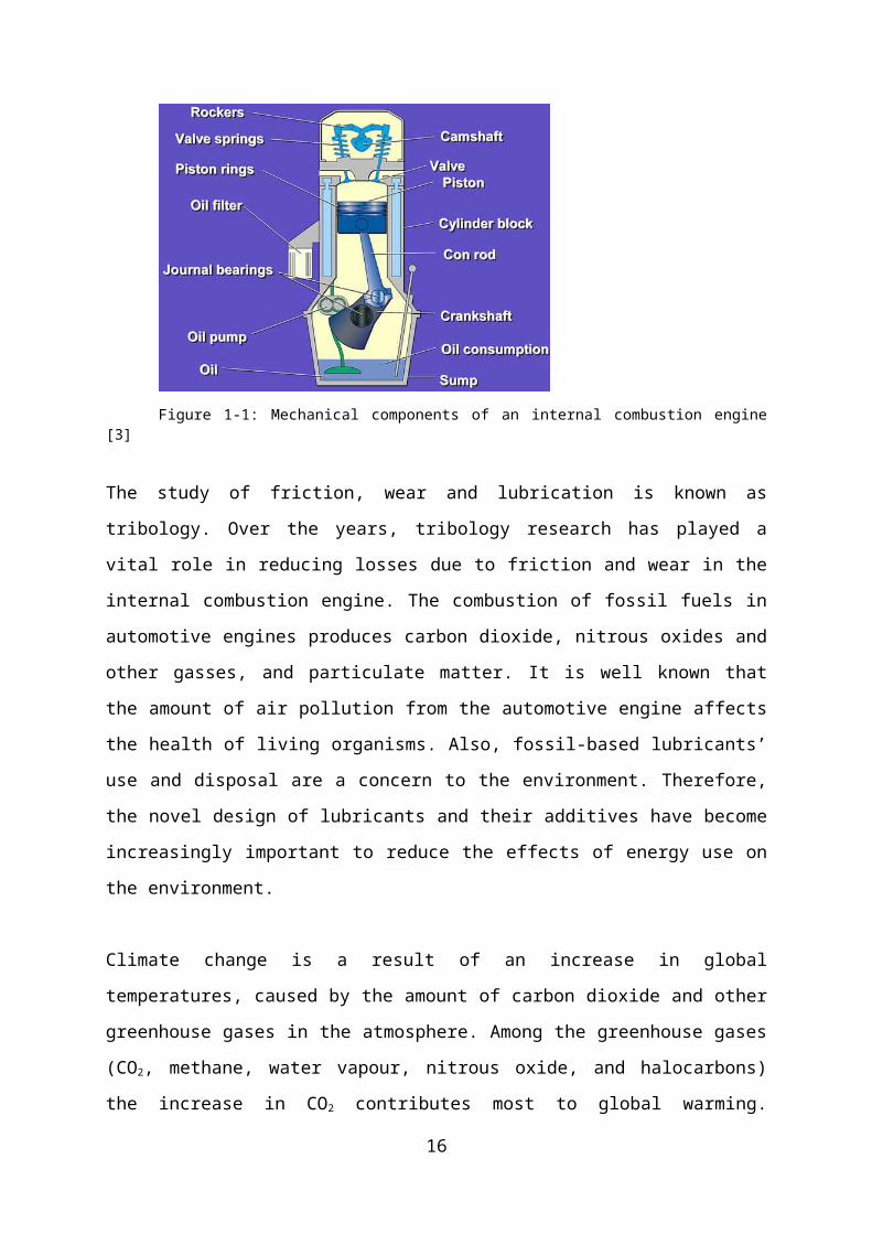
The internal combustion engine remains adaptable to most applications in power demands.
Some internal combustion engine parts (see Figure 1-1) experience relative motion during
operation. This results in the associated problems of friction, wear, and lubrication. It is an
issue that up to 48% of the energy developed in an engine is lost due to friction [3]. Friction
is the force that opposes motion in an interfacial contact under an applied load. The amount
11
of energy expended to overcome friction is (lost) not available for useful work. Wear i.e.
material degradation and/or removal is a consequence of friction and surface asperity contact.
Lubricants are materials that keep a pair of machine components’ surfaces from direct contact
during operation.
Figure 1-1: Mechanical components of an internal combustion engine [3]
The study of friction, wear and lubrication is known as tribology. Over the years, tribology
research has played a vital role in reducing losses due to friction and wear in the internal
combustion engine. The combustion of fossil fuels in automotive engines produces carbon
dioxide, nitrous oxides and other gasses, and particulate matter. It is well known that the
amount of air pollution from the automotive engine affects the health of living organisms.
Also, fossil-based lubricants’ use and disposal are a concern to the environment. Therefore,
the novel design of lubricants and their additives have become increasingly important to
reduce the effects of energy use on the environment.
Climate change is a result of an increase in global temperatures, caused by the amount of
carbon dioxide and other greenhouse gases in the atmosphere. Among the greenhouse gases
(CO2, methane, water vapour, nitrous oxide, and halocarbons) the increase in CO2 contributes
most to global warming. Therefore, emerging national and regional legislations seek to
reduce emissions of CO2, reduce global surface temperature and halt changes in regional
climate [4][5]. Internal combustion engines burn fuels and use lubricants from fossil sources.
Carbon dioxide is a major product of fossil fuel combustion in engines. Thus, CO2
legislations are passed on to original equipment manufacturers (OEMs) who then require
12

tribologists to design acceptable solutions to improve fuel efficiency, fuel economy and
reduce emissions. Over the years, the piston ring-cylinder liner contact is understood [6][7]
[8] to account for up to 50% of automotive engine frictional losses.
When engine friction is reduced, a higher percentage of energy developed from fuel
consumption is available for vehicle propulsion. Lubricant design is one of the solutions
toward engine CO2 emission reduction through reduced frictional losses. The base oil and
additive packages are carefully selected and blended to make a typical fully formulated
engine oil lubricant. Lubricant testing is required to prove lubricating oil’s performance.
These include laboratory, engine and field tests. Engine tests would prove that the
performance of the lubricating oil meets specific performance criteria.
At the 2015 climate change convention [9], an agreement was reached to pursue efforts that
would limit the increase in global average temperature to between 1.5 and 2oC. It is generally
observed that CO2 emission from fossil fuel is the main cause of climate change [5]. Thus,
CO2 emission reduction is considered very important by OEMs. Over the years, energy and
environment legislations require sustainable low emissions performance, low air pollution,
improved fuel economy, and increasing oil drain interval for automotive engine lubricants [3]
[10]. For mineral oil based lubricants, particulate emissions have been observed from their
combustion [11].
Fuels and lubricants from fossil sources are known to have high carcinogenic content, and
petroleum reserves are limited. These, along with the relatively higher cost of alternative
synthetic products, made fuels and lubricants from biological sources attractive. Thus, both
climate change and health effects of fuels and lubricants are essentials. Biolubricants are
natural, renewable, and non-toxic alternatives to mineral oil for lubricant formulation. It is
observed that biolubricants are being adapted for industrial and engine applications due to
environmental concerns [12].
Biolubricants are lubricants that use base oils from natural sources or bio-resources, typically
vegetables, with high biodegradability and low toxicity. The use of base oils like rapeseed oil,
palm oil, soya oil, groundnut oil and others for biolubricant formulation would give the
lubricant desirable properties including good lubricity, high viscosity index, low pour point,
higher flash point and a high level of degradability [13]. These biobased lubricants have
13
certain poor qualities which could be improved through chemical modification. Chemical
modification helps to improve a biolubricant’s sensitivity to hydrolysis, oxidative stability,
and poor low-temperature behaviour.
Also, biolubricants have higher affinity to metal surfaces, this makes them offer better
anticorrosion than mineral oils [12]. The chemical characteristics of biobased oils are
considered low risk to humans and the environment. Their friction and wear reduction
properties would be determined by additives packages. It is established that the additives
influence the toxicity and ash formation characteristics of a lubricant formulation [14].
The conventional additives contain toxic elements including sulphur, ashes, and phosphorus
(SAP). As biolubricant base oils are being considerable alternatives to mineral oil, similarly
non-toxic additives would be required. Environmentally acceptable lubricant additives can
complement biolubricants in lowering the release of carbon oxides, methane, nitrous oxides
and other greenhouse gases. The conventional additives include the AW additive, zinc
diakyldithio-phosphate (ZDDP). The ZDDP has a quality of being able to work with other
additives that offer necessary characteristics to the fully formulated lubricant.
Some other additives in a typical engine lubricant include the FM (i.e. MoS2), viscosity
modifiers, extreme pressure agents (containing S, P or/and Cl), dispersants, detergents,
corrosion inhibitors (containing Cu and Pb), antioxidants and pour point depressants [15].
For friction and wear reduction, NP additives are considered as partial or total replacement to
S and P-containing additives. Also, some combinations of NPs and ZDDP in oil are reported
to reduce friction and wear characteristics of sliding steel pairs [16, 17].
NPs of known solid lubricants, metals, ceramics and polymers are among emerging green
additives for lubricating oils and greases. Some of the known solid lubricants whose
nanoscale particles have been considered in nanolubrication include molybdenum disulphide
(MoS2), and tungsten disulphide (WS2) in various chemical and physical forms. Nanoscale
forms of carbon (C) are equally being studied as graphite, graphite oxide, graphene, graphene
oxide, nano-diamond, nano-onions, nano-horns, nano-rods, nanotubes, etc. Nanomaterials
based on metals and their oxides are among the many prospects for nanolubrication. These
include titania (TiO2), copper (Cu) and copper oxide (CuO), silica (SiO2), alumina (Al2O3),
boron nitride (BN), oxides of zinc, and iron (Fe) and iron oxides (Fe3O4, Fe2O3), etc.
14
NPs (solid phase), of sizes below 100 nm and of various shapes are usually dispersed in the
liquid (continuous phase) [18], thereby forming homogenous and stable colloidal dispersions.
Nanofluids [19], being colloidal solutions, are lubricants, coolants and other fluids used in
engineering systems; that resulted from the addition of NPs. Nanomaterials [20] are different
from traditional bulk materials due to their extremely small size and high specific surface
area. Lubricants and fuels can, therefore, be mixed with nanoscale materials to form colloidal
dispersions. As such, nanolubrication can be viewed as the application of nanomaterials in
mitigating some friction and wear challenges of fluid lubricated systems.
The characterisation, i.e. chemistry, structure, morphology, size, shape of nano-additives and
functionality of nanomaterial-based fuel, lubricant and grease additives [21][22] are areas of
current research. Recent developments of additive packages for automotive and other fluid
lubricated systems have found some merits in utilising metallic, ceramic and polymeric single
or multi-element (hybrid) NPs. These have been observed by many studies to offer FM, anti-
wear and extreme pressure improvements to lubricants in certain tribology situations. Some
nanolubricants, nanofluids and NP-based lubricant concentrates are commercially available.
Several products claim some anti-wear, load carrying capacity and FM benefits compared to
plain or fully formulated conventional mineral oil and bio-based lubricants.
NPs additives are potential green alternatives to sulphur (S) and phosphorus (P) based
additives. As well, NPs additives can function in a synergy [23] with the traditional ZDDP.
Many studies [24-30] have observed that NPs can be additives in bio-based or renewable
lubricants. The emergence and availability of Polyvit hybrid NPs led to a focus on its merits
as an additive in biolubricants. Polyvit may apply as ‘green’ additive in ‘green’ lubricants.
The physical properties of the lubricant are determined by standard methods like those of
ASTM, SAE, API, DIN and others. Some important properties of lubricants are kinematic
and dynamic viscosity, viscosity index, flash point, pour point, density, colour, shear
stability, corrosiveness, elastomer compatibility, water tolerance, homogeneity and
miscibility, ash, element content and foaming characteristics. These physical properties
should comply with the requirements of the OEM. Since lubricant functions to mitigate
tribological problems, it must be tested for friction and wear among others.
15
There are three levels of lubricant testing before being accepted for OEM use in engines.
These are from the simplified bench tests to the more expensive application or engine tests,
and then to very stringent field tests. Bench tests select a geometric configuration that
represents the relative motion that occurs in an actual machinery tribosystem. Some of these
tribological configurations include ball-on-flat reciprocating rig, pin-on-disc unidirectional
sliding, pin-on-cylinder, cylinder-on-cylinder and block-on-ring. The contact situation is
either conformal or non-conformal at the initial stage of a test [31][32]. This study adopts two
laboratory scale bench tests: namely ball-on-flat reciprocating test and pin-on-disc
unidirectional test, for the characterization of the lubricants and NPs additives.
1.3 Statement of the Problem
Environmental concerns make it important to reduce CO2 emission in internal combustion
engines. Lubricants are designed to reduce friction in engine operation and would lower the
fuel consumption levels. The lubricant base oil and additives are ideally to be such that are
non-toxic to humans and the environment. Thus, biolubricants are considered for lubricant
formulation as alternatives to the conventional mineral oil but need additives to perform
similarly. The NP additives systems are alternatives to some toxic additives, or can be used in
combination (e.g. with ZDDP) and need to be assessed.
1.4 Aim of the Research
This work investigates the possibility to employ Polyvit NPs as a non-toxic additive for
biolubricants. Rapeseed oil, without chemical modification, was selected for the study. Fully
formulated engine oil – SAE15W-40 was selected as a reference. The ball-on-flat and pin-on-
disc contact configurations are employed in the investigations. This is to understand the
evolution of friction coefficient, wear volume or wear rate, wear surface morphology and
mechanism, wear surface and tribofilm chemistry and assess the effectiveness of the NPs
additives in a lubricant.
1.5 Objectives and Scope of the Work
In order to provide proof of concept for the Polyvit NPs additives in a biolubricant;
laboratory tests, sliding contact friction analyses and wear surface characterizations were
carried out.
16
1.5.1 Objectives of the research
The objectives of the research were as follows:
1. Select appropriate test methods with enough sensitivity to allow comparison
between lubricant and lubricant-NPs mixture
2. Do tests defined in 1) to tribologically compare lubricant and lubricant-NPs
mixture
3. Use chemical analyses to investigate the characteristics of the NPs and the
lubricants
4. Analyse the friction and wear data from 2) and evidence from 3) to propose the
performance of lubricant and lubricant-NPs mixture in boundary lubrication
sliding.
1.5.2 Scope of Work
NPs additives application in lubricating oils is a very vast area of research, but this study was
limited to the following areas:
1. The automotive engine piston ring-cylinder liner reciprocating sliding contact and
boundary lubrication behaviour of the lubricant and the NPs additives.
2. One type of NPs additives: Polyvit hybrid NPs were used as supplied.
3. One biolubricant – rapeseed oil, was used as purchased in its raw form.
4. Laboratory bench tests were conducted at RT and at 100oC respectively.
5. One standard fully formulated mineral oil based engine oil – SAE15W-40 used as a
reference.
6. The concentration of the Polyvit NPs additives in the lubricants is 0.1 wt. %.
7. The ZDDP was mixed with the rapeseed oil at 1 wt. %.
1.6 Outline of the Dissertation
This dissertation is arranged as follows. Chapter 2 begins with the properties of lubricants
relevant to tribological performance. Following this, lubricant base oils are briefly
introduced, leading to the need for biolubricants as necessary alternatives to mineral base
oils. The engine lubricant additives that impact on friction and wear reduction are briefly
presented. Chapter 3 introduces tribology from the surface characteristics to friction and
boundary lubrication categories and laboratory-scale tribotest methods. This leads to wear
17
mechanisms and lubrication, especially of the piston ring-cylinder liner contact in the
automotive internal combustion engine.
Chapter 4 describes the development of understanding of the use of NPs additives in mineral
base oil, poly alpha olefin (PAO) oil and a biolubricant, rapeseed oil. These lead to the
introduction of the NPs used in the experiments, Polyvit. Chapter 5 then is a presentation of
the experiments on the HFRR to understand the behaviour of the NPs-lubricant mixtures in
boundary lubrication sliding. The analytical tools utilized for NPs and wear surface
characterisation are briefly described. The effect of the hardness variation in the EN-GJL-250
flat sample is briefly discussed.
The tribotests presented in Chapter 5 were reviewed for a lower load and a test of possible
synergy between the NPs and the AW additive, zinc dialkyl dithiophophate (ZDDP). This is
described in Chapter 6 using the high frequency reciprocating rig (HFRR), while the use of
the universal mechanical tester (UMT) is described in Chapter 7. The friction and wear
characteristics of the lubricants and lubricant-NPs mixtures are discussed. The wear surface
analysis explains the wear mechanisms and lubrication phenomena.
Chapter 8 consists of the conclusions of this study, its impact and usefulness to industry.
18
2 Base Oils, Additives and Lubricant Formulation
The physical properties of lubricants are described in the early parts of this chapter.
Following this, the base oil groups and alternative biolubricants are briefly explained.
Thereafter, the lubricant additives which affect tribological performance of the automotive
engine are discussed, with insights into their interactions in a lubricant. The chapter
concludes with the section on formulation of lubricants.
2.1 Introduction
The lubricant is the material used in tribological contacts to separate the peak asperities of
contacting surfaces. Lubricating oils are the most common form of lubricants. Lubricants are
available in semi-solid forms, such as greases. Also, there are solid lubricants for use in
contacts that operate in conditions where lubricating oils or/and greases cannot be effective.
Such contact and operating situations of high temperature and cases where oils and greases
can contaminate the system or surrounding environment require solid lubricants. Graphite,
MoS2, WS2 bulk materials are among well-known solid lubricants. Lubricating oils must be
designed to perform under the operating conditions of temperature, load, pressure, and
environment.
The modern industry use lubricating oils (which is referred to as lubricants in this study) for
prevention of wear between contacting tribological surfaces in machinery or engine.
Lubricants equally serve as heat transfer mediums. Also, in the internal combustion engine, a
lubricant seals the gap between piston compression ring and the cylinder liner wall. Along
with these three functions, lubricants suspend matter and help clean up the internal
combustion engine [33]. Lubricant consists of base oil and selected additives. The additives
are usually selected to provide the properties not present in the base oil. The additives for
mineral oil-based engine lubricants are briefly explained in Section 2.4.
As explained by Mackney and co-workers [34], a lubricant should mitigate the tribological
problems of a machinery or engine sustainably across the range of operating temperature. The
lubricant must be optimally useful over an extended lifetime. Both low and overly high
temperatures affect the performance of a lubricant adversely. Lubricant solidification or
gelation occurs at low temperature and starves the tribo-contact of lubricant. Also, the
19
lubricant film thickness is reduced at high temperatures, where loss of lubricant viscosity and
lubricant film collapse in the tribo-contact can result in excessive wear. The high operating
temperatures enhance oxidation of lubricant. Lubricants need to neutralize contaminants like
soot particles from combustion.
The fundamental requirement of lubricants to control friction and wear relates to their
tribological performance in a system at the operating conditions. Also, there is another aspect
of lubricant degradation over its useful lifetime. The degradation of a lubricant is usually
monitored as an important indicator of its quality over the operational period. A lubricant can
degrade through oxidation because of operation in air and at high temperatures. Lubricant
degradation can lead to thickening, sludge formation, damage and corrosion of the tribo-
surfaces. Along with the quality, the economic and environmental aspects of lubrication are
important. The volume of lubricant used in a system determines the cost of replacement.
Also, lubricant replacement implies the release of waste lubricant to the environment [35].
This is where biodegradability of a lubricant becomes important. This is discussed in the
section on Biolubricants.
2.2 Properties of Lubricating oils
The properties of lubricating oils can be classified into physical, thermal, temperature and
other properties [35]. However, an industry-focussed study by Henderson and May [36]
explains fifteen physical properties of fully formulated automotive engine lubricants namely:
kinematic and dynamic viscosity, shear stability, pour point, cloud point, volatility, foaming
characteristics, element content, ash, density, flash point, colour, corrosiveness, water
tolerance, elastomer compatibility and homogeneity and miscibility. Although these
properties are not measured in this study, they are fundamental properties of lubricants.
2.2.1 Physical Properties of Lubricants
The physical properties of lubricants are used to compare them, determine their area of
application and service life [36]. These properties are viscosity, density and specific gravity.
The viscosity of a lubricant is affected by temperature and pressure. While the viscosity of a
lubricant decreases with increasing temperature, it increases with increasing pressure. The
viscosity index of a lubricant is an expression of its viscosity variation with temperature, at a
constant pressure, usually atmospheric pressure. This is important to automotive engine
20
operation. The influence of pressure on viscosity is rather important in heavily loaded
contacts, like rolling contact bearings and gears [35]. As this study is on the trial of a NPs
additive for automotive engine lubricants at RT and 100oC, the influence of temperature on
the properties will be discussed.
2.2.1.1 Viscosity
The viscosity of a lubricant is a measure of its resistance to flow or shear. The dynamic
viscosity of a lubricant is the measure of its resistance to shear. The measure of a lubricant to
flow through a capillary tube of known geometry and dimensions under gravity determines
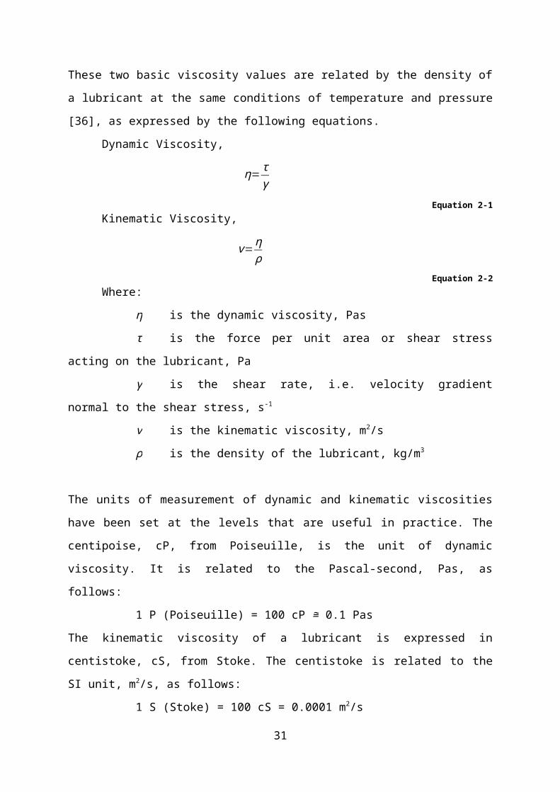
its kinematic viscosity. These two basic viscosity values are related by the density of a
lubricant at the same conditions of temperature and pressure [36], as expressed by the
following equations.
Dynamic Viscosity,
η= τγ
Equation 2-1Kinematic Viscosity,
v= ηρ
Equation 2-2Where:
η is the dynamic viscosity, Pas
τ is the force per unit area or shear stress acting on the lubricant, Pa
γ is the shear rate, i.e. velocity gradient normal to the shear stress, s-1
v is the kinematic viscosity, m2/s
ρ is the density of the lubricant, kg/m3
The units of measurement of dynamic and kinematic viscosities have been set at the levels
that are useful in practice. The centipoise, cP, from Poiseuille, is the unit of dynamic
viscosity. It is related to the Pascal-second, Pas, as follows:
1 P (Poiseuille) = 100 cP ≅ 0.1 Pas
The kinematic viscosity of a lubricant is expressed in centistoke, cS, from Stoke. The
centistoke is related to the SI unit, m2/s, as follows:
1 S (Stoke) = 100 cS = 0.0001 m2/s
21
The ability of a lubricant to separate contacting surfaces in relative motion is related to its
viscosity at the operating temperature and pressure. Under hydrodynamic sliding conditions,
the lubricant film thickness for friction and wear reduction is dependent on lubricant
viscosity. But this is not necessarily the case under boundary lubrication sliding, as the
lubricant additives determine the tribofilm formation and adsorption lubrication mechanisms.
It is pertinent to note that whilst many base oils (basestocks) are Newtonian fluids, the
additives turn fully formulated lubricants to non-Newtonian fluids. Thus, the viscosity of an
automotive lubricant will change with the shear rate, while the temperature remains constant
[36]. This behaviour affects a lubricant’s dynamic and kinematic viscosities.
A lubricant’s viscosity relates with the shear rate, shear stress and temperature. There are
industry specifications for automotive lubricant viscosity determination and classification.
The kinematic viscosities of engine oils are usually specified at 100oC and 40oC.
In automotive engine lubrication, there are measures of viscosity relevant to optimal engine
operation. Cranking viscosity, pumping viscosity, high-temperature high-shear viscosity
(HTHSV), gelation index, viscosity of sooted lubricants and shear stability are considered as
essentials to engine oil performance. These six types of viscosities are briefly explained as
described by Henderson and May [36].
1. Cranking Viscosity refers to the lubricants dynamic viscosity measured in the cold
crank simulator (CCS). It is well known that engine cranking speeds is relevant to its
ability to start, often in cold conditions; therefore, the cranking viscosity is very
important. It is used to determine the winter (W) grade of the SAE J300 engine
lubricant classification. The cold crank simulator is a rotational viscometer that
measures dynamic viscosity at a constant shear stress. In the CCS, dynamic viscosities
are measured at shear rates of 104 – 105 s-1 and temperatures from -35 to -5oC.
2. Pumping Viscosity also has to do with engine start at low temperature. It is a measure
of the lubricant’s ability to flow to the oil pump during low-temperature start of an
engine. The W grade pumping viscosity and yield stress are measured in the mini-
rotary viscometer (MRV) as described in ASTM D4684 and stated in SAE J300.
3. High-Temperature, High-Shear Viscosity (HTHSV) is a measure of dynamic viscosity
of an engine lubricant at high shear rates of over or equal to 106 s-1 at 100 or 150oC.
This is relevant to temperatures and shear rates in the engine journal bearings.
22
4. Gelation Index relates the viscosity to temperature during cooling of the lubricant.
The temperature of maximum gelation index is the gelation index temperature. These
parameters are measured with constant shear rate equipment at a shear rate of 0.2 s -1.
While the temperature range for measurement is -5 to -40oC, the cooling rate can be at
1oC/h (ASTM D5133) or 3oC/h (ASTM D7110).
5. Viscosity of Sooted Lubricants is a variant of the pumping viscosity for engine
lubricants corrupted with black soot fuel combustion products. Soot agglomeration
makes this measurement challenging. The Scanning Brookfield instruments and the
mini-rotary viscometer are used to determine this viscosity value. This viscosity is
determined using ASTM D6895 method at a temperature of 100oC.
6. Shear Stability of a lubricant is its resistance to viscosity loss due to the lubricant flow
through narrow passages at high shear rates. The viscosity loss is termed ‘percent
shear losses. There are standard bench and sequence engine tests designed to
determine engine lubricant shear stability, like ASTM D5275, ASTM D7109 and
ASTM D6278. The tests, usually at 100oC, help to reduce the thermal and oxidative
effects of degrading the polymer molecules of the viscosity index improver (VII)
additive.
These tests related to lubricant viscosity are required by the original equipment manufacturers
(OEMs) in their lubricant selection process. Depending on the intended operating conditions
and environment of the automotive engine, the OEM can subject the lubricant to a range of
viscosity test methods. The piston ring-cylinder liner contact in the engine often operates
from RT to temperatures beyond 100oC, and goes through all the three lubrication regimes.
However, the boundary lubrication sliding condition of peak asperity interaction is critical,
where adsorption lubrication depends on lubricant additives. Under this condition, the six
aforementioned lubricant viscosities are necessary for lubricant flow into the contact, but not
as important as in hydrodynamic or mixed lubrication conditions.
23
2.2.1.2 Viscosity Index
Temperature has a strong influence on lubricant viscosity, and this influence is usually
expressed as the viscosity index. As temperature rises, lubricant viscosity falls rapidly. There
are instances of very sharp decline in lubricant viscosity, like 80% fall in viscosity with a
25oC temperature rise. Lubricant viscosity at operating temperature affects the lubricant film
thickness under hydrodynamic and mixed lubrication regimes [35]. As explained in
Stachowiak and Batchelor [35], the viscosity index compares the kinematic viscosity of the
lubricant to those of two reference lubricants with known sensitivity of viscosity to
temperature. The viscosity index (VI) of a lubricant can be calculated from the equation:
VI= (L−U )(L−H )
× 100
Equation 2-3Where:
U is the kinematic viscosity of the lubricant at 40oC, m2/s
L and H are values that correspond to the lubricant’s kinematic viscosity at
100oC, read from a table (ASTM D2270).
The viscosity index is therefore an inverse measure of the decline of the viscosity of a
lubricant. This can be high, i.e. more than 150, for multigrade and synthetic lubricants; or
low, i.e. up to 100 for mineral oil-based engine lubricants [35]. Some biolubricants are known
to have viscosity index in excess of 200 [37]. Lubricants with high viscosity index are
required for automotive engine lubrication due to the usually high operating temperature. One
of the additives for engine lubricants is the viscosity index improver (VII), used to enhance
the viscosity index of engine lubricants. This minimises the decline in lubricant viscosity with
increasing engine temperature.
2.2.1.3 Lubricant Viscosity Classification
The Society of Automotive Engineers (SAE) has the general classification of automotive
lubricants. Engine lubricants are graded to SAE J300 classifications [35, 38]. The SAE J300
is the standard limit for engine lubricant classification based on rheological terms only. It is
used by engine manufacturers for lubricant viscosity grades for an engine. The lubricant
makers used the SAE J300 standard in formulating, manufacturing and labelling respective
24
lubricants. The SAE viscosity grades for engine lubricants are in two series: those with the
letter ‘W’ and those without the letter ‘W’.
As explained in the SAE J300 document [38], the single viscosity grades with the letter ‘W’
are those determined by maximum low-temperature cranking and pumping viscosities, and a
minimum kinematic viscosity at 100oC. Also, single-grade lubricants without the letter ‘W’
have their viscosities determined by a set of minimum and maximum kinematic viscosities at
100oC, and a minimum high-shear-rate viscosity at 150oC. The SAE J300 defines multigrade
or multiviscosity-grade lubricants by the following two criteria:
1. Maximum low-temperature cranking and pumping viscosities corresponding to
one of the W grades, and
2. Maximum and minimum kinematic viscosities at 100oC and a minimum high-
shear-rate viscosity at 150oC corresponding to one of the non-W grades.
The SAE J300 standard specification is commonly used for commercial available engine
lubricants. The heavy-duty diesel engine lubricant SAE 15W-40 is a multigrade lubricant, as
specified in the SAE J300. The SAE 15W-40 has a minimum high-shear-rate viscosity at
150oC of 3.7 mPas, a maximum low-shear-rate kinematic viscosity at 100oC of a value lower
than 16.3 mm2/s; and a minimum low-shear-rate kinematic viscosity at 100oC of 12.5 mm2/s.
2.2.1.4 Density and Specific Gravity
The density of a lubricant is its mass per unit volume, with the unit, kg/m3. On the other hand,
the specific gravity is the quotient of the mass of an equal volume of lubricant at temperature
t 1, and that of laboratory distilled water at temperaturet 2. The ASTM D1298 is used to
determine the density and specific gravity of lubricants. The specific gravity of lubricant is
usually stated at 15.6oC, and it is dimensionless [35]. Since the density of a lubricant changes
with temperature, the temperature at which a measurement is taken should be stated. Density
is used with other properties to characterize a lubricant. A common instance is its use for the
conversion between kinematic viscosity to dynamic viscosity of lubricants, petroleum
products and other industrial liquids [36].
25
2.2.2 Thermal Properties of Lubricants
The specific heat and thermal conductivity of lubricants are essential thermal properties for
assessment of the thermodynamic effects in lubrication, like cooling and temperature of
lubricated tribological surfaces. Stachowiak and Batchelor [35] explains the two properties
with formulae for their estimation where necessary. Lubricant specific heat varies with
temperature and increases with polarity or hydrogen bonding of molecules. Also, the thermal
conductivity of a lubricant varies linearly with its temperature. As is the case with specific
heat, so it is with the thermal conductivity. It is also affected by hydrogen bonding and
polarity of lubricant molecules.
2.2.3 Temperature Characteristics of Lubricants
The temperature characteristics and the temperature range for specific application of a
lubricant are very important. The operating temperature of an automotive engine is such that
enhances the decomposition of lubricants by oxidation. Also, at low temperatures, lubricants
can solidify. During engine operation, lubricants can form emulsions with water and release
deposits on the tribo-pair surfaces. Therefore, temperature-induced lubricant degradation can
be detrimental to machinery operation. An example is when the acidity level of oxidized
lubricants enhances the chemical corrosion of engine components. A lubricant’s temperature-
related characteristics include: pour point, cloud point, flash point, fire point, volatility and
evaporation, oxidation stability and thermal stability [35]. The automotive industry-focussed
explanation of these properties is given by Henderson and May [36].
2.2.3.1 Pour Point and Cloud Point
The pour point of a lubricant is the temperature 3oC higher than the temperature at which no
movement of the lubricant is observed. The pour point is an indicator of dispensability of a
lubricant at low temperatures. Although it cannot be related to pumpability or engine start-
ability, the pour point is important to the automotive engine exposed to low temperature. The
cloud point is the temperature when wax crystals first begin to form in a lubricant. At this
temperature, wax precipitation is visible in the bottom of a lubricant container. If the cloud
point is higher than the pour point, the lubricant has a wax pour point. Also, lubricant shows
‘viscosity pour point, if the pour point is reached without a cloud point. The cloud point of an
automotive lubricant is usually measure on base oils, and determines whether the base oil is
fit for purpose [35][ 36].
26
2.2.3.2 Flash Point and Fire Point
The flash point of a lubricant is the temperature at which it forms a flammable mixture with
air. Thus, the flammable mixture will ignite in the presence of an ignition source. The flash
point is used in safety and shipping classification of a material. Also, it can be adopted to
determine if a relatively non-volatile lubricant is contaminated with a flammable material. On
the other hand, the fire point of a lubricant is the temperature at which enough vapour is
produced for continuous burning after ignition. The fire point is also used for safety purposes.
Both the flash point and fire point of lubricants increase with increasing molecular weight
[35] [36].
2.2.3.3 Volatility and Evaporation
Lubricants become more viscous at elevated temperatures and tend to dry out. Volatile
additives in a lubricant can be lost by evaporation, leading to increase in viscosity. This
coupled with frictional heating would further increase the temperature and evaporation of
lubricant. Therefore, volatility relates directly with evaporation losses [35]. Engine OEMs
consider lubricant volatility important because of oil consumption, engine deposits and air
pollution effects [36].
2.2.3.4 Oxidation Stability
The oxidation stability of a lubricant is its resistance to molecular breakdown or
rearrangement at high temperatures in atmospheric air. Lubricant oxidation influences the life
of a lubricant. Lubricants oxidize on exposure to air and this increase with increase in
temperature. Other factors affecting oxidation include lubricant refinement, and operating
conditions. Oxidation stability is improved through refining. But lubricant improved
oxidation stability comes at a high cost and poor boundary lubrication characteristics.
Therefore, lubricant selection is a compromise depending on the desired performance of the
lubricant. Additives can be used to control lubricant oxidation. Lubricant oxidation produce
acidic compounds that increase the corrosiveness of the lubricant, deposit of insoluble
materials on the tribo-pair surfaces and reduction of the flow of oil in an engine. These make
oxidation stability very important. Once a lubricant is degraded through oxidation, a
replacement is required. This leads to higher operating costs. In the automotive engine
operation, lubricant replacement becomes more frequent [35].
27
2.2.3.5 Thermal Stability
The thermal stability of a lubricant is its ability to maintain its molecular structure at elevated
temperatures in the absence of oxygen. A thermally unstable lubricant breaks down at
elevated temperature without oxygen. This contrasts with oxidation where molecular
breakdown occurs in the presence of oxygen. While thermal stability can be improved by oil
refining, it cannot be improved with lubricant additives. Lubricant additives usually have a
thermal stability lower than that of base oils. Generally, thermal degradation of lubricants
occurs at temperatures higher than that of oxidation. Therefore, the maximum temperature at
which a lubricant can be used is subject to its oxidation stability [35].
2.2.3.6 Element Content
Lubricants and their additives are chemical substances. The chemical elements contained in a
lubricant and its additives are therefore essential part of investigation of lubricant quality. The
primary elements of interest in fresh lubricants are barium, calcium, magnesium, phosphorus
and zinc. Some lubricants formulations contain boron, sodium potassium and molybdenum.
The analytical spectroscopy tools, like SEM/EDX, XPS, etc. can measure boron, phosphorus
and sulphur. Sulphur and phosphorus have lower measurement accuracy than other elements.
For instance, the detergents used in a lubricant formulation would be observed as Ba, Ca and
Mg in the EDX spectra; while Na and K may be contaminants. The elements of used
lubricants help to understand their fitness for purpose. For used lubricants, the concentrations
of elements like Fe, Sn, Pb, Cu and other wear metals help in understanding the lubricant life.
2.2.4 Additive Compatibility and Solubility in Lubricants
The compatibility issues of additives in lubricant are important in lubricant selection for
operating condition and materials of a tribo-couple. The additives in a lubricant should not
give visible or measurable evidence of reaction with one another, like a change in physical
appearance (colour) or smell. Compatible additives are such that their individual properties
are supportive in a lubricant’s performance. Compatibility also has to do with the lubricant
and materials of the surfaces in a tribological contact, and between one lubricant and another
in a combined usage.
28
For example, mineral oils produce carburization when used with red hot steels; while
rapeseed oil does not. On the other hand, solubility implies that lubricant additives remain
dissolved over the temperature range of engine operation. Whether a lubricant is stored or in
service its additives should not agglomerate or separate. For example, sulphur is insoluble in
lubricant under atmospheric conditions and it separates in-service and during storage. But at
higher temperature and pressure, sulphur can be used as an additive [35].
2.3 Lubricant Base Oils
Mineral base oils are lubrication grade oils produced from refining crude oil. Base oils
produced through chemical synthesis are referred to as synthetic base oils. In recent years,
due to environmental concerns, lubricants are being developed from bio-based oils. Most
mineral base oils used to formulate engine lubricants are from paraffinic petroleum oils. This
is because the automotive engines require lubricants with a high viscosity index and good
oxidation stability. Base oils should fulfil certain criteria including low temperature fluidity,
volatility, oxidation stability, carbon residue, flash point and cloud point.
If several base oils meet the required criteria, then that with the lowest cost may be selected.
In lubricant formulation, the viscosity and viscosity index of the base oils are essential
parameters. It is the viscosity of the base oil that would ensure hydrodynamic lubrication. It
must be high enough for lubrication film formation, but not too high to increase friction
losses in the oil. The viscosity index is important for lubricants used in systems that operate
over a wide temperature range, like in the automotive engine [39].
Conventional engine oils are those well-known formulations based on mineral oils derived
from petroleum or fossil sources. For conventional lubricants, the base oil has evolved over
the centuries. Ancient records (1400 BC) show beef and mutton fat (tallow) used to lubricate
chariot axles. Thus, before the availability of petroleum-based oils (1852), animal fats were
the earlier lubricants. The performances of the early petroleum-based oils were lower than the
animal-based oils. The base oil industry learnt over time, especially with the coming of the
automobile. Since the 1920s, lubricant manufacturers have been processing base oils for
better performance.
29
The early categorization of base oils by the Society of Automotive Engineers in 1923 was
based on viscosity: light, medium and heavy. Some of the methods employed to improve base
oil performance over the past decades include: clay treating, acid treating, SO2 treating,
solvent refining, hydro-treating, hydrocracking, catalytic dewaxing and hydro-isomerization
[40]. Table 2-1 shows the American Petroleum Institute classification of base oils in Groups I
– VI, according to their chemistry. This is widely used in the lubricant industry.
Table 2-1: Lubricant base oil groups [41][42]
Base oil group
Base oil nature Sulphur (wt %)
Saturates (wt %)
Viscosity Index (VI)
Group I Solvent dewaxed HVI oils
>0.03 and/or <90 80-120
Group II Hydrogenated or hydrocracked oils
≤0.03 and/or ≥90 80-120
Group III VHVI oils ≤0.03 and/or ≥90 ≥120Group IV Polyalphaolefins (PAOs)Group V All base oils not included in Groups I-IV or VI Group VI All poly (internal olefins)
Mineral base oil can be selected from either Group I or II, while synthetic base oil belongs to
Group III. Group I base oils are those processed by solvent refining, which removes
aromatics and improves the lubricating quality of the oil. They contain less than 90%
saturates more than 0.03 wt% sulphur and have a viscosity index between 80 and 120. Group
II base oils are made using the hydro isomerization process, and are almost water-white in
colour. On performance, their purity implies that the base oil and the additives in the fully
formulated lubricant can have both long shelve and useful lives. These base oils contain at
least 90% saturates, up to 0.03 wt% sulphur and have similar range of viscosity indices like
those in Group I.
Group III base oils have at least 90% saturates and up to 0.03 wt% sulphur, but with viscosity
index not less than 120. A viscosity index of over 120 is taken as very high, thus these oils
are referred to as very high viscosity index (VHVI) oils. Base oils in Group III are synthetic
and regarded as dry, because of low sulphur and fully saturated non-polar hydrocarbon
molecules. Polyalphaolefin (PAO) is fully synthetic and classified into Group IV.
Polyinternal olefin (PIO) is fully synthetic base oil in its own category - Group VI. All other
30
base oils not included in Groups I-IV and VI and classified in Group V. Base oils from bio-
resources fall into Group V.
2.4 Biolubricant as Alternative to Mineral (base) Oil
Biolubricants consist of oils from natural biological and agricultural sources. The
characteristics that make these Group V base oils potential alternatives to mineral base oils
are rapid biodegradability, low eco-toxicity and being from renewable sources. Biolubricant
composition would have one bio-based natural oil or bio-based synthetic oil. The bio-based
oils are selected from the following: natural or synthetic vegetable oil, natural or synthetic
animal oil, genetically modified (GM) vegetable oil, natural or synthetic tree oil, and
mixtures thereof [85]. Mineral oil-based lubricants are used for automotive and industrial
applications in large quantities. They are polluting by water and soil contamination and also
by CO2 emissions.
Another factor for finding alternatives to mineral oil lubricants is the high cost of disposal.
Most rapidly biodegradable lubricants use saturated and unsaturated ester base oils. Some
biolubricants are triglycerides (e.g. rapeseed oil and sunflower oil); esters of modified
vegetable oils, semi-saturated, trans-esterified ester oils with natural fatty acids. Rapeseed oil,
palm oil, soybean oil and other natural oils and fats are known to exhibit low coefficient of
friction; good wear protection, higher flash points and higher viscosity indices; compared to
those of mineral oils. But their application is limited by high thermal oxidation, hydrolytic
stress and poor cold-flow properties. Through chemical or genetic modification and
additivities, these limitations can be improved [85]. Quinchia [43] observed that a certain
pout point depressant additive improves the low-temperature properties of rapeseed,
sunflower, castor, soybean oils.
The use of biolubricants is, among other factors, due to their availability in parts of the world
with relatively expensive and short supply of mineral oil. Also, biolubricants are free of
sulphur-containing compounds and chemicals harmful to human skin and health. It has been
31
observed that additives used for mineral oil may not be effective in biolubricants. Thus,
biolubricants may require specially developed additives. Some biolubricants have been
adopted due to their ability to meet relevant environmental requirements. Some of these oils
are rapeseed oil in Europe and soya-based lubricants in the United States. Also, castor oil-
based lubricant is used in total loss applications like, two-stroke engine and chain bar
lubrication [44]. These environment, health and safety issues encourage biolubricants use.
Lubricant disposal is a problem where biodegradability becomes relevant. Mineral oil-based
lubricants are not totally biodegradable (not more than 40%), thus making waste oil pollution
of the water system an issue. Biolubricants are a type of environmentally friendly and rapidly
(up to 100%) biodegradable lubricants. Biolubricants can be adopted for loss-lubrication
applications, such as those where leakages to the soil and waterways occur. As the drive
toward biodegradable lubricant continues, it has been observed that vegetable oils are the
most biodegradable base oils, followed by animal fats and esters.
Vegetable oils biodegradation is classified as being ultimate. This is because a vegetable oil
would be totally converted (100% biodegraded) by microorganisms and produce CO2, CH4,
H2O, mineral salts and biomass. Base oil biodegradability is classified through the
Organization for Economic Co-operation and Development (OECD) testing. In a typical
biodegradability test, while mineral oil exhibits 15-35%, vegetable oil has 70-100% primary
degradability. Biodegradability guidelines are as follows [85]:
i. Primary biodegradation: The chemical structure of oil is altered by
microorganisms, resulting in the change of some measurable properties of that
substance.
ii. Ultimate biodegradation: The level of aerobic degradation obtained when the test
oil is totally converted by microorganisms. The products include CO2, CH4, H2O,
etc.
iii. Readily biodegradable: This implies that at least 60% of the test oil carbon has
been converted to CO2 in 28 days. Less than 5% of the base oils used in
formulating conventional lubricants are readily biodegradable.
iv. Inherently biodegradable: This is a classification of oils with some evidence of
biodegradation in any test of biodegradability. The standard OECD testing is
mostly adopted.
32
Automotive engine lubricants are being improved for better emissions, durability of the
engine and fuel economy. In order for biolubricants to be adopted as crankcase lubricant, it
should meet a number of standard performance requirements [85]. Some of the standard
performance requirements where biolubricants are attractive include low volatility, high
viscosity index and boundary lubrication adsorption properties of their polar ester groups.
Also, regarding the cleansing function of engine lubricants, biolubricants can solubilize polar
contaminants.
The environment is a major factor for the preference of biolubricants over mineral oil-based
lubricants. Some area where biolubricant use is influenced by environmental factors are total
loss lubrication, military, off-road, mining, marine and fishing equipment, agricultural
tractors and hydraulic systems, railroads, dredging and forestry systems. The poor cold-flow
behaviour and low thermo-oxidative stability of biolubricants can be improved through either
or both of genetic and chemical modifications [45]. The prevailing trend with biolubricants
based on vegetable oil is that their high oleic acid concentrations improve friction and wear
performance. This is through densely packed monolayers formed on the surface of metals,
especially ferrous metals, in a tribological contact [46].
The fatty acid composition of a biolubricant determines its application. Biolubricants like
Rapeseed oil, have physicochemical properties which depend on the carbon chain distribution
and modification. These properties make biolubricants useful in many industrial applications,
thereby becoming alternatives to petroleum products. Biolubricants in their unmodified form
can be adopted for total loss lubrication systems and as circulation oils in oil-refreshing
systems for lubrication of four-stroke engines. In this case the lubricant is consumed with the
fuel and there is no waste lubricant to dispose.
The ester groups in rapeseed oil have high affinity towards metal surfaces to form protective
films on contacting surfaces. [13]. Rapeseed oil is a base oil (75 vol.%) for automotive engine
biolubricant formulation. As a vegetable oil, rapeseed is effective as a boundary lubricant.
This is because of the reaction of the highly polar fatty acids which reacts with metal surfaces
to form protective hydrocarbon layers. The fatty acids from biobased oils have been used in
formulating high-performance lubricants [85].
33
2.5 Engine Lubricant Additives
The additives are chemicals that give the lubricant its tribological behaviour and performance
for an internal combustion engine. Lubricant additives are usually added in small quantities to
the base oil to impact on its lubricating ability and durability. The functions of lubricant
additives are to improve the friction and wear behaviour of a lubricant, especially for
adsorption on the contacting surfaces. Also, additives improve the extreme-pressure
lubrication characteristics of the lubricant. Other qualities of a lubricant that are improved by
additives are oxidation resistance, corrosion and contamination control, reduction in pour
point, and inhibition of foaming. Viscosity index improvers are a class of additives that keep
lubricant viscosity from falling excessively with increasing temperature [35]. The additives
for the mineral oil-based engine lubricants are briefly discussed in the following subsections.
Lubricant additives are categorized into three groups as performance additives, oil protection
additives and surface protection additives. Out of these three, the surface protection additives
such as FMs, AW and extreme pressure additives are more relevant to tribological
performance than others. The performance additives include viscosity modifiers, pour point
depressants, seal swell agents and antifoams. The oil protection additives are antioxidants for
reduction of base oil degradation. The additives are usually prepared in carrier base oil for
improved handling and lubricant formulation [47].
2.5.1 Surface Protection Additives
The chemicals used to improve wear and friction properties of lubricants are the most
important additives [35]. This class of lubricant additives consists of the FMs, AW agents,
extreme pressure agents, dispersants, detergents, and rust and corrosion inhibitors. Surface
protective additives work by combining a hydrocarbon tail with a polar head group. The polar
head group contains one or more of these elements N, O, P, and S atoms. While the
hydrocarbon tail is soluble in the oil phase, the polar head group gets attracted to metal
surfaces or other polar materials like soot particles, oxidized oil sludge, and other deposits.
The careful combinations of different polar heads with different hydrocarbon tails make FM,
AW, and extreme pressure behaviours possible [45].
34
2.5.1.1 Friction Modifiers (FMs)
The automotive engine has many components being lubricated by the same lubricant. There
must be a balance between the lubricant performances or behaviour requirements at different
tribo-contacts in the engine which operate in different lubrication regimes. In a lubricated
system, while viscous drag occurs within the lubricant, relative motion occurs between the
contacting surfaces. Low-viscosity lubricants can reduce viscous drag, but the viscosity must
be low to the extent of not being able to support hydrodynamic lubrication of the main, big
and little-end bearings. Highly loaded contacts like piston ring-cylinder liner, piston skirt-
cylinder liner and cam-follower; operate in the mixed and boundary lubrication regimes.
These severe contacts require FMs to reduce friction [45].
FMs are in two groups that work in different ways. These are organic FMs and organo-
molybdenum FMs. Organic FMs are straight-chain hydrocarbons of approximately 18 carbon
atoms. They have polar head groups that can be an amine, amide, carboxylic acid, ester,
phosphoric phosphonic acid. As is common to surface protective additives, the polar head
group attaches to metal surface by boundary lubrication or absorption mechanisms [35]. The
surface protection mechanisms of organic FMs can be schematically represented as shown in
Figure 2-1. The adsorption mechanisms of physisorption and chemisorption are explained
under boundary lubrication mechanisms in Section 3.4.2.2. Multilayers of adsorbed polar
head groups form a strong film on the contacting surfaces. This tribofilm is responsible for
reduced coefficient of friction in the tribo-contact. Once attached to the metal surface,
organic FMs work immediately [45].
Figure 2-2: Surface protection mechanisms of organic FM. (Adapted from [45])
35
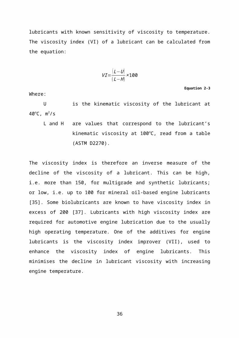
Figure 2-3: Mechanism of FM of Mo-type additives [45]
However, the organo-molybdenum or Mo-type FMs work in a different way. Mo-containing
additives depend on the frictional energy in the contact to convert Mo-containing species into
MoS2. MoS2 has a lamellar structure which allows its layers to slide past each other easily.
This results in a reduced friction in the tribo-contact, as shown in Figure 2-2. Due to the
requirement of a chemical reaction, Mo-type FMs need high loads and temperatures.
Although either of the two types of FMs can enhance the performance of lubricants regarding
high contact pressure, they are limited to a level, above which they become ineffective [45]
[48].
2.5.1.2 Antiwear (AW) Additives
Engine operations at higher temperatures above the effective operation range of FMs require
AW additives. There are several types of AW additives, but engine lubricant formulations
commonly adopt zinc dialkyldithiophosphate (ZDDP). Other AW additives include
tricresylphosphate and phosphate esters used in gas turbine lubricants [35]. Also boron-
containing detergents and dispersants and borate esters provide AW properties and can
behave like ZDDP in lubricant [45].
AW additives are added to base oil in concentrations of 1 to 3 wt.% [35]. In tribo-contact
with high contact pressure, AW additives undergo chemisorption reactions with the metal
surface. These reactions result in formation of polyphosphates surface protective layer. The
contact temperature is a factor for initiation, propagation and possible destruction of the
chemisorbed tribofilms. When the contact temperature, combining lubricant and frictional
heating together, exceeds 250oC the tribofilms can break down [45].
36
Figure 2-4: Mechanism of formation of Zn, S and P-based tribofilms [45]
ZDDP is the AW additive present in most automotive engine lubricants. Spikes [49]
explained the history, development, chemical structure and tribofilm formation process of the
ZDDP. However, Mackney [45] proposed the general mechanisms of operation of AW
additives as depicted in Figure 2-3. The processes A –D are itemised as follows:
A. Surface cleaning: Breaking-in and mild wear at the early stage of sliding remove
metallic oxides from the tribo-pair surfaces, thereby exposing bear metals to the
lubricant and the surrounding environment.
B. Chemisorption of the AW additives elements onto the surface.
C. Chemical reaction of the additives chemical elements with the surface material
elements to produce a pad-like protective layer.
The conditions for these reactions to occur include high frictional heating and
contact temperature due to high contact pressure or applied load.
D. Growth of the reaction layer and layer-on-layer compaction to form thicker AW
film or tribofilm.
ZDDP and other AW additives are known to function as shown in Figure 2-3. ZDDP is
known to reduce the problem of valve train wear and oil degradation in automotive engines,
but it is a major source of sulphur and phosphorus in lubricants. The environmental pollution
problems of sulphur and phosphorus meant that alternatives are being sought for ZDDP [35].
37
ZDDP is an AW additive for control of two-body wear in critical automotive engine
components [50], like the piston ring-cylinder liner contact and the valvetrain.
The tribological behaviour of lubricated metal surfaces is influenced by the action of AW
additives. This transient lubricating action is also affected by mechanical mixing of additives
with the metallic surface materials. In a study by Dienwiebel and Pohlmann [51], the AW
additive ZDDP is observed to provide two forms of wear protection mechanisms under
different tribological conditions. Firstly, when the stress is high, ZDDP forms AW films that
reduce material removal (wear) for a short period of time. Secondly, when the stress is
moderate or low, the ZDDP influences the mechanical and chemical characteristics of the
contacting surfaces. This is through mixing with the materials at the tribo-pair interface and
modifying the shear stress. The friction coefficient is thereby reduced. Also, the films and
interfacial modification support reduced wear on a long-term basis.
2.5.1.3 Extreme Pressure Additives
The surface-active additives categorized as ‘extreme pressure’ behave in a similar way as
AW additives. The extreme pressure additives prevent seizing under high contact pressure or
high temperature or both conditions. In tribological situations like heavy or shock loading and
extended operational life of lubricant, extreme pressure additives can protect contacting
surfaces in engines more than AW additives [45].
Figure 2-5: Extreme pressure additives mechanisms [45]
38
Such very severe boundary lubrication conditions occur in heavily loaded gears. The
chemical compounds used for extreme pressure boundary lubrication additives contain at
least one of these elements: sulphur, phosphorus, antimony, iodine or chlorine. The
commonly used chemicals in lubricants are those using sulphur as the reactive species. While
AW additives prevent wear, extreme pressure additives control wear [45].
The basic process of wear control is like the four-step operation of AW additives, as shown in
Figure 2-3. However, the fourth step is different as the iron sulphides reaction products at the
asperities penetrate the surface (Figure 2-4 (a)). These sulphides are easily sheared as relative
motion progresses and the iron sulphide (or iron salt) is removed from the metallic
component (Figure 2-4 (b)).
The process of removing metallic sulphides is controlled to avoid localized welding and
tearing of contacting surfaces. Thus, instead of adhesive or scuffing wear, the contacting
surfaces are made smoother as shown schematically in Figure 2-4 (c). The reaction of
extreme pressure additives with the tribo-pair surface is affected by additive concentration. If
this is too high then excessive corrosive wear can occur. Also, if the additive concentration is
too low, the contacting surfaces may not be fully protected [35][ 45].
2.5.2 Interaction between Additives
The chemical composition, structure and performance of lubricating oil additives can be
enhanced or reduced through their interaction. The interaction of some AW and extreme
pressure additives with other additives can lead to ineffective lubrication. One example is
when fatty acids reduce the lubricating performance of ZDDP. Another scenario is when one
or more chemical element(s) of an additive is replaced by another element from another
additive, thereby altering the expected tribofilm chemistry, and lubrication mechanism [52].
One of such scenario is the replacement of zinc by lead in internal combustion engine
lubricants running on leaded petrol. In this case, ZDDP becomes PbDDP with lower AW
performance [52]. The combination of the films of FM laid on the relatively thicker AW
films of ZDDP can lead to reductions in both friction and wear simultaneously [46].
39
In cases where the tribological behaviours of the NPs alone in a lubricant are studied,
surfactants, detergents and other additives are not added. This would allow for the
understanding of the NPs’ lubrication performance, without the influence of another chemical
substance. For instance, in the study of TiO2 NPs in base oils [53], both surfactants and
dispersant agents were not employed. In this case, a uniformly distributed lubricant-NPs
mixture was achieved through mixing by mechanical stirrer and shaking with bearing ball in
a glass bottle. However, it was necessary to re-homogenize the mixture before being used in
the tribological test.
2.6 Formulation of Automotive Engine Lubricants
Engine oils are the class of lubricants for internal combustion engines running on fuels like
diesel, gasoline and other automotive fuel packages. Light duty engine oils are those used in
passenger cars, while heavy duty oils are used in larger vehicles, for example with engine
sizes from 2 to 16 litres [54].
There are four substances that make up an automotive lubricant, namely: base oil, additives,
viscosity index improver and pour-point depressant. Biolubricant base stocks are different
from mineral oil basestocks in that the latter consists of non-polar hydrocarbons, whereas the
former has polar ester functional groups. There are no set of additives specifically
manufactured for biolubricant formulation. So, the available additives for mineral oil-based
formulations can be adopted for biolubricants in automotive engine lubrication. One way to
do this is by blending a biolubricant with about 10-30 % mineral oil to lower the polarity.
Thus, the conventional additives could be solubilized in the blend in the required amounts of
between 10 and 14 % [51].
Additives add and/or improve the desired characteristics to the lubricant which the base oil
cannot provide. This is because base oils have poor AW film formation ability across the
conditions of engine operations, especially temperature changes. Additives are materials
prepared for the improvement of one or more of AW, antifriction, chemical and physical
40
properties of base oils. Lubricant additives enhance performance and extend the useful life of
the equipment. Engine oil formulations make use of several additives which work together.
As explained by Bart [51], engine lubricant additives can be placed in three categories,
namely surface protection or surface active additives, performance-enhancing additives and
lubricant protection additives. These are shown in Figure 2-5. The functions of the surface
active additives are to reduce the coefficient of friction and wear in the engine tribo-pairs.
These are the most relevant set of additives to tribological performance.
Surface active additives include AW agents like ZDDPs and ethyl stearate; FMs like fatty
acid esters and organomolybdenum compounds; extreme pressure agents like MoS2; rust
inhibitors, corrosion inhibitors, detergents, dispersants and tackiness agents. Performance-
enhancing additives include viscosity-index improvers for improvement of the viscosity-
temperature relation of the lubricant. Polymer materials are common viscosity index
improvers. Other performance-enhancing additives are pour-point depressants, emulsifiers,
demulsifiers, deposit control additives and thickeners. Lubricant protective additives are
those that improve the ability of the lubricant to withstand the engine operating conditions.
These are antioxidants, like phenolics and aromatic amines; foam inhibitors, antileak agents
and biocides [51].
Figure 2-6: Materials in engine lubricant formulation (Adopted from [51])
Many factors influence the choice of oil additives such as: operating temperature, load,
mating materials and surfaces, fuels in the engine combustion system, etc. Also, selected
41
additives should improve engine efficiency, minimise toxicity and avoid degradation of
lubricant on the shelf and while in use. The additive package should form either a stable
solution (or suspension) with the base oil, to avoid additive drop-out (aggregation) over the
lubricant useful life.
Cost and permissible concentration in lubricant limit the introduction of additives to base oil.
Due to relative thickening of oil by additives and the resulting reduction in fuel economy,
lubricants with minimum effective additives are preferred [55]. Lubricant formulations are
usually proprietary information. The performance of a formulated lubricant depends on its
chemical, physical and film forming properties. As explained by Bart [51], biolubricant base
stocks should meet these five criteria: solubility with additives, good low-temperature
properties, biodegradable, good lubricity and high flash point.
2.7 Conclusions
The properties of lubricating oils (or lubricants) such as viscosity, viscosity index and
classification of lubricants on viscosity basis have been discussed as physical properties. The
density of a lubricant is observed to be the conversion parameter between the dynamic and
kinematic viscosities of a lubricant. The specific heat and thermal conductivity were
discussed as thermal properties of lubricants. The lubricant property sections concluded with
the temperature characteristics such as pour point, cloud point, flash point, fire point,
volatility, oxidation stability, thermal stability and chemical element content.
The lubricant additives are to be carefully selected so as to be compatible with the base oil.
Lubricant base oil Groups I-VI was discussed with attention on mineral oil being the group
mostly utilized for automotive engine lubricant formulations. The recent attention towards
biolubricants is observed to be because of their health and environmental benefits compared
to carcinogenic fossil-based mineral oil and toxic additives. The engine lubricant additives
are in three categories such as surface protection, performance and oil protection additives.
However, tribo-contact surface protection additives are those most relevant to tribological
performances. These surface protection additives were discussed as FMs, AW additives and
extreme pressure additives.
42
The interaction between additives in a lubricant are such as should guide the lubricant base
oil and additives selection. Fully formulated lubricants consist of the base oil and the
additives (or additive package). In fully formulated lubricants, both the base oil and the
additives should minimise friction and wear across the temperature range of engine operation.
The lubricant temperature characteristics should allow for flow at low temperatures, and safe
handling, shelving and transport.
Also, in the face of stringent environmental legislations, lubricants are required to be
biodegradable and the additives non-toxic. This is where biolubricants and non-toxic NPs
additives have potentials. Biolubricant formulation would utilize existing conventional
additives because no additives have been specifically prepared for them yet.
So also are emerging additives that often tested in a combinatorial form with conventional
additives. As the knowledge of emerging additives improves, perhaps some may be used
specifically for biolubricant formulation. The tribology of the automotive contact of interest
in this study: the piston ring-cylinder liner contact is briefly described in the next chapter.
43
3 Tribology and Tribotesting in Boundary Lubrication Regime
In this chapter, the basics of tribology and tribotesting in boundary lubrication regime are
presented. Also, the characterisation of surfaces is briefly explained. The three constituent
parts of tribology: friction, wear and lubrication are briefly described. This leads to the
Stribeck curve and the Lambda parameter for categorisation of lubrication regimes. The
boundary lubrication mechanisms are described regarding the piston ring-cylinder liner
contact in the automotive engine.
3.1 Tribology
Tribology encompasses the scientific and technological understanding of materials, machine
elements and rigid bodies for optimal design and operation of dynamic interfaces in
engineering systems [56]. Conventionally speaking, tribology encompasses (but not limited
to) the understanding, description, modelling and optimal control of several material and
system properties. Material properties relevant to tribology include hardness, surface
characteristics, ductility, and others. Friction and wear are the major tribological system
properties often studied. Lubrication is widely known as the means of mitigating both friction
and wear in surfaces under relative motion.
Tribology is the inter-relational study of friction, wear and lubrication. Tribological study has
over the years included more areas like; surface engineering, coating technology, contact
mechanics, corrosion, material and surface characterization, oil analysis, failure analysis, etc.
44
The inter-disciplinary nature of tribology has led to study areas like tribo-chemistry, tribo-
corrosion, tribo-physics, bio-tribology, micro-tribology, nano-tribology, etc. Therefore,
tribology research exists in a wide range of industries involved in motion. Examples include;
sports, medicine, oil and gas, transportation, power generation and virtually all manufacturing
technologies.
Environment-friendly or green tribology is “the science and technology of the tribological
aspects of ecological balance and of environmental and biological impacts” [57]. Recent
understanding of climate change, health, pollution and environmental issues of fossil-based
fuels and lubricants has influenced current research directions. Legislation related to
automotive system manufacture makes research into bio-based or green energy alternatives
imperative. It has been reported that virtually all current petroleum fuels and lubricants have
some degree of on-going research toward sustainable alternatives [58]. Naturally occurring
oils seem to be the focus in this search, just as it was before the advent of the petroleum era.
Relative motion usually involves pairs of rigid bodies forming dynamic interfaces. Machinery
pairs can be a mix of hard and softer materials, similar and/or dissimilar materials, or variety
of simple and/or complex combinations. As rigid bodies or machine elements experience
varying operational conditions, they simultaneously undergo wear, friction and expense of
energy to overcome it. Other forms of geometric, material and chemical degradations occur
like corrosion, fretting, erosion, fatigue, etc. As technology evolves, new contacts are
designed with the need to keep interfaces separated. Lubricants are the materials usually
incorporated between tribo-pairs for lower friction and reduced wear.
The lubricant can exist across the three phases – solid, liquid and gas. Friction reduction is
one of the ways to lower the energy consumption of any machinery and with a lubricant
separating the peak asperities of contacting surfaces, wear will be minimised. Functionally
speaking, lubricants help in making both energy and material savings. Automotive lubricants
are understood to impact on energy conservation and acceptable environmental management.
For durability and marketable performance [59], lubricant properties, lubrication mechanisms
and understanding of service factors will complement engine components, materials and
lubricant design processes.
45
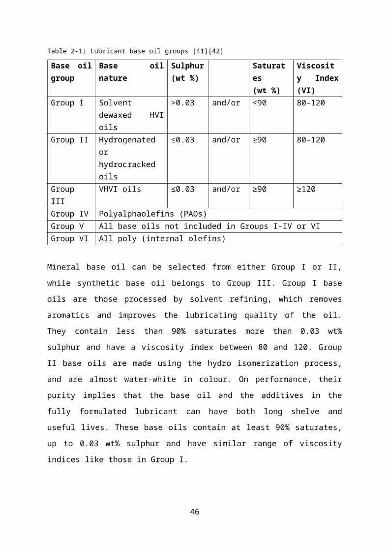
In addition to friction and wear reduction, a lubricant should be able to remove heat and
contaminants from tribo-contacts. Also, lubricants can clean and protect contacting surfaces
from corrosion. Additionally, internal combustion engine oils should be able to neutralize
acids formed during combustion. Thus, the lubricant protects against corrosion. It is essential
that a lubricant transports protective chemicals to the contacts where they are needed, and
transport wear particles away from where they are generated. Engine oil should remain
effective under all driving conditions, short-trip and cold-start conditions. Under high load
and high temperature, fluid film lubrication, lubricant additives should be able to interact
with sliding surfaces to form AW films. Lubricant degradation depletes the AW and other
additives, necessitating engine oil drain and change [3].
The application of a lubricant and its operating conditions will influence its performance
characteristics. Usually additives are the major enhancer of lubricant performance. The basic
state of a lubricant is known as the base oil and additives to this base oil provide the
properties required in a lubricant operation for desired effectiveness. Lubricant additives can
be placed in three groups [60] as performance, oil protection and surface protection additives.
The AW, extreme pressure and fiction modifier additives are important to tribology. Other
necessary engine oil additives [61] include: antioxidants, viscosity index improvers,
dispersants, detergents, antirust agents, corrosion inhibitors, demulsifiers, pour-point
depressants and antifoam agents.
3.2 The Surface in Tribology
The surfaces of tribo-pairs need to be examined to understand their lubrication behaviour,
wear mechanisms and other surface features related to performance. As explained by
Hamrock [62], form error, waviness and roughness exist on surfaces. For lubricated surfaces,
roughness is an essential parameter. Surfaces are influenced by their manufacturing
processes, and can be; inhomogeneous or homogeneous, deterministic or random and
isotropic or anisotropic. Contacting and non-contacting methods have been developed for
measurement and analysis of surface profiles.
The measured roughness profiles depend on the orientation of surface features, stylus trace
direction, and the profile filter [63]. In tribology testing, it is usual practice to profile and
examine surfaces before and after tests. This is because the wear of materials is usually
46

evidenced by wear scar morphology, surface film chemistry and related surface features.
Also, the wear scar or wear track width and geometry are used for wear volume analysis.
The two most widely used surface roughness parameters are the centre-line average (CLA)
value, Ra, and the root mean square (RMS) value, Rq. The CLA and RMS are expressed as
follows:
Ra = 1L∫0
L
|z|dx
Equation 3-4
Rq = √ 1L∫0
L
z2 dx
Equation 3-5
47
Where:
L is the sampling length, and
Z is the height of surface above mean
The RMS roughness parameter is known to help distinguish between a relatively gently
undulating surface and one with a spikier profile [64]. The squared term gives greater
significance to surface variations some way from the mean. Many other statistical parameters
are employed to describe surfaces, like kurtosis, skewness, etc. as necessary. As observed by
Sedlacek and co-workers [65], one cannot express a straight forward relationship between
surface roughness and tribological behaviour. This is because the Ra of different surfaces is
not exactly same. Surface preparation of the flat specimen is an issue for consideration.
The two members of a tribo-pair should be prepared with attention paid to their surface
roughness, topography and texture. Specimen preparation methods and processes are known
to have notable effects on the friction and wear behaviour of tribo-pairs under dry and
lubricated conditions [65]. Some researchers [66-68] using the ball-on-flat tribology test
configuration; express the need to consider the direction of grooves (lay) on the flat
specimen’s surface. This is because the reciprocating slider direction – parallel or
perpendicular – to ‘lay’ can change the lubrication regime. This could erroneously give lower
coefficients of friction. A way to minimise this error is to use the same flat piece, placed at
the same orientation, for repeated tests under similar conditions.
3.2.1 Surface Characterisation
The evidence of wear is usually observed on the mating surfaces. These could be viewed with
the naked eye in cases of macro-level wear. A profilometer can be used to measure the
surface roughness of a test sample before and after tribotest. Surface profiles can give the
wear depth, the wear track width, and material (volume) transfer for wear volume analysis. In
relatively simple contacts with minimal wear, the optical microscope may be appropriate; but
in more complex conditions where tribofilms are formed on mating surfaces, high level
microscopes are necessary. A Scanning Electron Microscope (SEM) combined with Energy
Dispersive X-ray Spectroscopy (EDX or EDS) can be employed to obtain both the surface
morphology and surface chemical analysis. The wear track surface tribofilm chemical
analysis would reveal the engine lubricant additive elements, with protective properties.
48
As explained by Stachowiak and co-workers [69], surface micrography after tribotesting
provides vital information on wear and friction processes. Both interacting surfaces and wear
particles need to be examined for appropriate explanations. Microscopy examinations of wear
tracks help to determine wear mechanisms which brought about surface features like
tribofilms formation, material transfers, reaction products, grooves, pits and so on. They
observed that all wear processes change the mating surfaces; from surface topography to the
chemistry of the surface and sub-surface zones. Tribofilm formation on wear track surface is
important in lubrication studies. The tribofilm chemistry can help researchers to determine
whether the films are from reactions between the lubricant and worn material, the lubricant
additives, or atmospheric gases and water.
Microscopes are employed to characterize the topography, microstructure and chemical
elemental analysis of tribological surfaces. The optical microscope serves to provide some
initial information about the wear track. Measurements of the wear track width can be done
on the optical microscope. But the information from the optical microscope is usually not
sufficient to explain a wear phenomenon. So, the SEM has become very useful to reveal
details of the wear mechanisms. Many techniques have been developed to help reveal
different features of the wear surface and subsurface. Some of these techniques are:
Transmission Electron Microscopy (TEM), Atomic Force Microscopy (AFM), Scanning
Tunnelling Microscopy (STM), etc. They are often combined for wear surface examination
and chemical analysis.
3.3 Friction
Friction is a tribological system property that occurs between two bodies which are both in
contact and relative motion at the same time. Friction studies cover external: static, sliding
and rolling; and internal or viscous friction within a fluid. Tribological components
experience friction in dry, boundary and lubricated phenomena. Wherever two bodies are in
rubbing contact, the frictional force is the force resisting the tangential motion of one body
relative to another. The coefficient of friction, COF or µ, is the ratio of frictional force to
normal load. The coefficient of friction expresses the severity of friction [70]. The simplistic
representation of two machine components in tribological contact is shown in Figure 3-1. The
Coefficient of friction is expressed as:
49
μ= Frictional forceNormal force
Equation 3-6
Figure 3-7: Simple representation of two machine components in tribological contact
Friction is usually overcome by the expense of energy within a tribological system. The aim
in tribology is to minimise the frictional force with respect to optimal energy saving in a
system. As explained by Stachowiak [52], friction studies has evolved from the four
empirical laws of Leonardo da Vinci and Amontons. The laws express the relationship
between the tangential friction force and the normal force or load. The laws also establish the
independence of the friction force from both the apparent contact area and the sliding speed.
These laws hold for moderately loaded sliding contacts at moderate velocities.
The mechanisms responsible for the cause and development of friction and energy loss
depend on the contact conditions. For instance, viscous shearing within the lubricating film is
the cause of the friction force in full-film lubricated contacts. In boundary lubricated contacts
the interactions between asperities of opposing solid surfaces cause the friction force. This is
because the surfaces of machine parts or solid bodies are not completely smooth [70].
Another contributing factor is the presence of wear debris or contaminants between the
contacting surfaces.
Boundary lubricated contacts have asperities interactions including adhesive bonding, elastic
and plastic deformations. Elastic and plastic deformations are dominant in boundary
lubrication sliding. These deformation mechanisms and surface adhesion are prevented by
tribofilms formed by lubricant additives. With boundary lubricants, moderate levels of
50
coefficients of friction are possible. Wear damages include ploughing or grooving, micro
cutting and micro fracture.
The adhesion theory (Bowden and Tabor) shows that the adhesive high friction force,
especially in dry contacts, causes high coefficients of friction. This can result in scuffing and
frictional seizure. Also, the adhesive component of friction can be high in boundary
lubricated sliding, depending on the effectiveness of the lubricant additives and the operating
conditions. When the coefficient of friction is low, wear damage can be through material or
film transfers. The ploughing term is added to the adhesion component of friction to account
for plastic deformations [35].
Two forms of plastic deformation affect the frictional force and coefficient of friction,
namely: wedge formation and ploughing. Wedge formation drives a wave of plastically
deformed material over the contacting surfaces. The ploughing component of plastic
deformation pushes material up to the edges of a wear track or friction zone. The coefficient
of friction of a tribological interfacial system depends on its operating parameters including
normal load, temperature and sliding speed and mode [52].
For instance, the reciprocating bi-directional sliding (mode) is different from the
unidirectional sliding situation. As such, there is no exact direct variation between friction
force and normal load. Also, the properties of the rough contacting surfaces affect the
evolution of friction. As friction brings about wear of surfaces in contact, the geometry and
alignment of assemblies are altered. This friction and wear induced geometric alterations
generate vibrations of the tribological system. The excessive vibrations result in noise
emission which is harmful and should be minimised [52]. Thus, friction mitigation processes
lead to reductions in noise of a system.
51
3.4 Boundary Lubrication
Boundary lubrication is a regime of lubrication where the lubricating mechanisms are
independent of the bulk material properties of the lubricating oil. In this condition, the
frictional force is controlled by the lubricity or oiliness of the tribofilms. Tribofilms are thin
films initiated and promoted by the interfacial relative motion of a tribo-pair with the supply
of a boundary lubricant. Fully formulated lubricating oils have chemical or polymeric
materials added in small quantities, for desirable performance under boundary lubricated
sliding.
These additives are designed to form surface protecting films (tribofilms) under tribological
action. The tribofilms’ formation and ability to separate contacting sliding surfaces depend on
the molecular structure of the lubricant; and the adherence of the molecules to the metal
surface. The surface roughness of the tribo-pair is an important factor in the effectiveness of
tribofilms lubricating action. Tribo-pair surfaces are usually with low average surface
roughness. The molecular lengths of oils are in the order of 0.0025 µm, which is about 1 % of
typical surface asperity heights.
As explained by Williams [70], thin layers of a lubricant resulted in low friction behaviour.
Boundary lubrication additives are such that their molecules readily absorb and form layers
with strong forces on metal surfaces. Some of these are organic alcohols, amines or fatty
acids having long chain molecules with active polar end groups. The boundary lubricant
should have strong bond with the metal surface. There are physical and chemical sources of
these bonds. The electrostatic forces between the molecules and the metal surface provide the
possible physical bond.
The chemistry of the lubricant interacting with that of the metal surface could initiate and
promote tribofilms. While the physical mechanisms can be reversible totally, the mechanisms
based on lubricant and surface chemical reactions leads to some permanent surface
modification. Both the physical and chemical tribofilms formation mechanisms are affected
by surface reactivity and test temperature. The additive concentration is another factor that
should be sufficient for optimal performance, but not influence the bulk properties of the oil.
52
The oil or lubricant behaves as a conveyor for boundary lubricating additives. The operating
temperature should be below that where either the additives or its tribofilm decomposes for
effective boundary lubrication [70].
The need to design lubricant additives for high temperature operations led to the use of the
AW additives, zinc dialkyldithiophosphate, ZDDP. This chemical contains zinc, phosphorus
and sulphur. It forms polymeric and viscous tribofilms of thickness in the range 0.05-0.5 µm,
thicker than those of lubricating oils. This is close to the range of average surface roughness
of automotive engine tribo-pairs. Thus, ZDDP could protect surfaces from seizure, excessive
wear and augment the lubrication mechanisms under hydrodynamic and mixed lubrication
regimes. The surface chemical evidence of the tribofilms is measured by electrical contact
resistance and SEM/EDS surface chemical analysis [70].
3.4.1 Theory of Boundary Lubrication
Boundary and extreme-pressure regimes of lubrication often coexist in tribological situations
where hydrodynamic, mixed and elasto-hydrodynamic lubrication are ineffective. In this
case, the occurring lubrication mechanisms include adsorption, sacrificial films, amorphous
layers etc. on the contacting surfaces. These interacting mechanisms ensure that the
machinery is kept in operation. Tribologists continue to develop the understanding of
boundary lubrication mechanisms because of their practical importance in automotive
contacts such as piston ring-cylinder liner, and steel gears. Also, metal-working tools employ
at least one of these mechanisms for prevention of seizure, severe wear and high coefficients
of friction [52].
The additives in the lubricant control the boundary lubrication mechanisms. The cost of the
additives is usually very low compared to that of the machinery being lubricated. Therefore,
the additives can be sacrificed for large tribological benefits. The additives form protective
layers that reduce coefficients of friction and wear loss. The lubricating mechanisms are
related to the load capacity and interfacial frictional temperature. The principle of boundary
lubrication is explained, based on coefficient of friction [52]. The coefficient of friction, COF
or µ, is defined as the ratio of the frictional force ‘F’ and the normal load ‘W’ applied to the
surface.
53
µ = FW
Equation 3-7
Interfacial contacts occur at asperities peaks which are somewhat dry. Therefore, the true
total contact area is sum of the individual contact areas between the asperities.
If the adhesion component of friction is the main friction mechanism between the asperities,
and that other effects like ploughing are low; then the frictional force is:
F = At τ Equation 3-8
Where:
F is the frictional force, N
At is the true contact area, m2
τ is the effective shear stress of the material, Pa
The applied load can be expressed in terms of contact area, i.e.:
W = At P y Equation 3-9
Where:
Py is the plastic flow stress of the material (related to the indentation
hardness), Pa.
P y ≈ 3σ y Where σ y is the yield strength of the material, Pa.
Substituting for ‘F’ and ‘W’ into Equation 3-3 yield:
μ= τP y
Equation 3-10
This model explains the boundary lubrication, such that: materials of low shear strength and
high hardness are required to obtain low coefficient of friction. These conditions are
practically incompatible. The formation of a surface layer with low shear strength on hard
solid substrates in a tribological contact can yield low coefficients of friction [52].
54
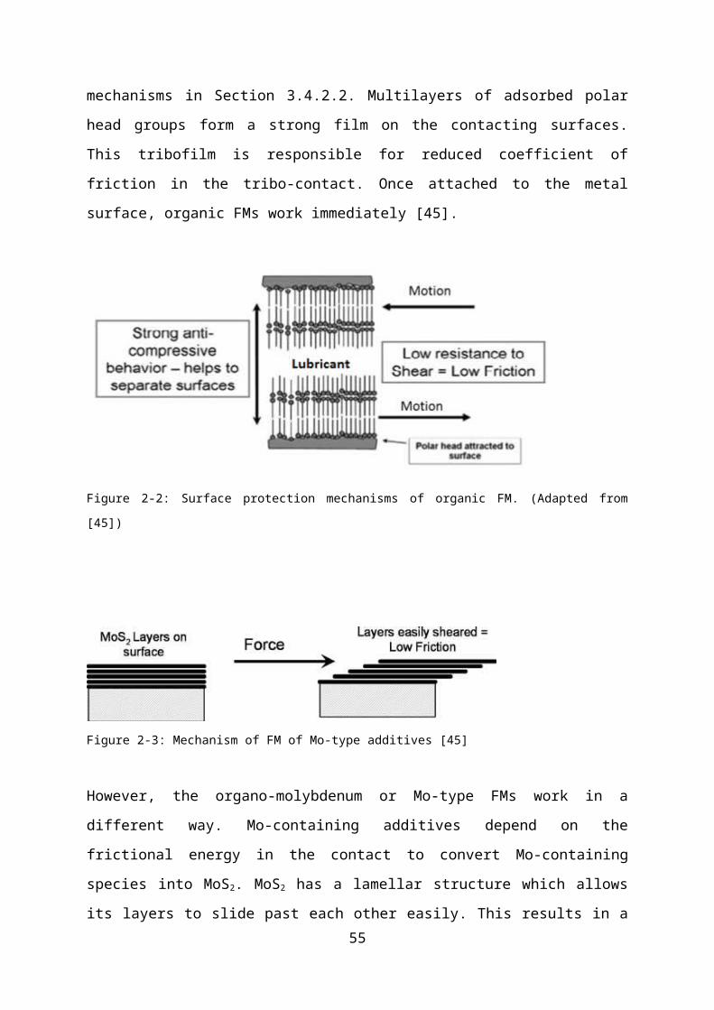
3.4.2 Categories of Boundary Lubrication
The interrelationship between the applied load and operating temperature is used to classify
the mechanisms of friction and wear reduction under boundary lubrication sliding conditions.
While the contact surface temperature can be either low, up to 150oC, or high, in excess of
150oC; the applied load or contact pressure can be low, medium or high [52]. The lubrication
mechanisms are explained in the following categories:
1. Low temperature-low load lubrication mechanisms
2. Low temperature-high load lubrication mechanisms
3. High temperature-medium load lubrication mechanisms
4. High temperature-high load lubrication mechanisms
These categories are briefly explained in the following sub-sections.
3.4.2.1 Low Temperature-Low Load Boundary Lubrication Mechanisms
When a tribo-pair operates at high sliding speeds and loads, hydrodynamic lubrication is
maintained in the contact. But, with decreasing sliding speed, the hydrodynamic film
thickness reduces till the opposing asperities interact. This is further explained by the
Stribeck curve. However, in certain contact conditions at low speed, tribo-pair surfaces can
be separated by thin layer of lubricant. The linear and polar molecules of the lubricant form a
protective thin film for lubricating the sliding contact [35].
The opposite ends of polar molecules are known to form pairs through strong van der Waals
forces. These pairs are bonded on the contacting surfaces as a viscous layer. The adsorbed
layer of lubricant remains aligned with the surfaces and lubricates the sliding interface. Either
the contact pressure (or load) and temperature affect these adsorbed layer, and could break
down when the limits are exceeded. These mechanisms of boundary lubrication are limited to
contact conditions of low temperature up to 50oC and low contact pressure up to 2 MPa [35].
3.4.2.2 Low Temperature-High Load Boundary Lubrication Mechanisms
The mechanism of boundary lubrication in sliding contacts with contact pressures up to 1
GPa, and at surface temperatures between 100 and 150oC is very important to the automotive
industry. This is generally called ‘adsorption lubrication’. In this lubrication mechanism, a
low-shear-strength layer is formed by the adsorption of the lubricant and additives on the
wear track. As expressed in Equation 3-6, Section 3.4.1, adsorption lubrication reduces the
55
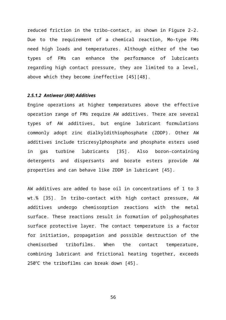
effective shear stress ‘τ’ at the interface without affecting the plastic flow stress ‘Py’ of the
substrate; thereby reducing the coefficient of friction of the sliding contact.
COF, μ= τP y
Equation 3-11
The shear stress reduction occurs through the planes of weakness in the low-shear-strength
layer, parallel to the plane of sliding. The adsorbed layers based on polar organic lubricants
form on metallic surfaces. Fatty acids and alcohols form polar molecules on metallic
surfaces. There is a long history of these molecules as ‘oiliness additives’. The adsorbed
layers of organic polar molecules enhance friction reduction [35].
The lubrication mechanism of the adsorbate is influenced by its polarity. Polar molecules are
asymmetrical with different chemical affinity at either end. For example, “one end of a
molecule which is the carboxyl group of a fatty acid, ‘-COOH’, is strongly attracted to the
surface of the metal, while the other end which is an alkyl group, -CH3’, is repellent to
almost any other substance”. Organic compounds like alcohols and amines have useful
amount of polarity, but the fatty acids are very effective polar lubricants or additives [35].
Absorption lubrication is in two categories, namely: physisorption and chemisorption.
Physisorption or physical adsorption is the classical form, whereby the attachment or
detachment of adsorbate molecules has reversible changes on the metallic surface or the
adsorbate. In this mechanism, van der Waals or dispersion forces bond the substrate to the
adsorbate. This reduces the coefficient of friction at ambient temperatures [35].
At higher temperatures, different materials exhibit transitions from low-to-high coefficients
of friction. The interaction between physisorption and chemisorption is known to also affect
this transition temperature. This is because materials have different reactivity to induce
chemisorption, which can co-exist with physisorption, or replace the low-shear-strength
layers. Chemisorption or chemical adsorption is rather irreversible or partially irreversible.
This form of lubrication involves chemical bonding between the adsorbate and the substrate
[35].
56
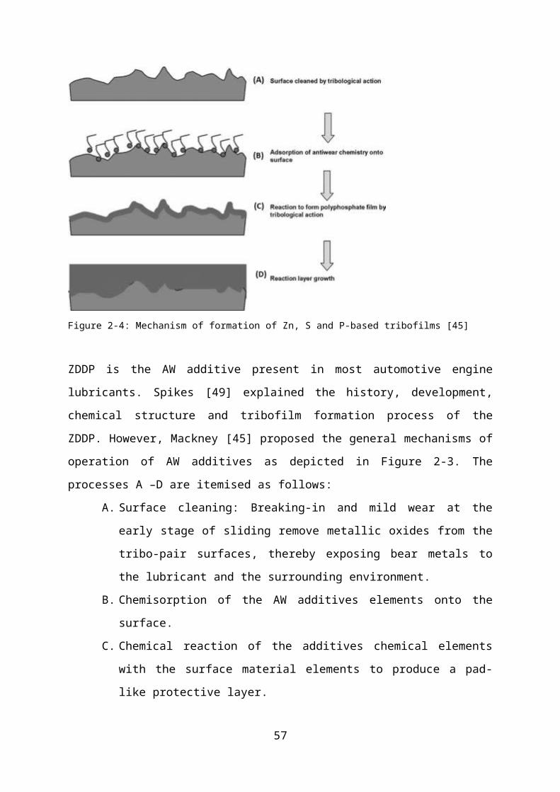
The reactivity of the substrate material influences the strength of chemical bonding between
the adsorbate and the substrate. Ferrous metals are reactive, making chemisorption to have
practical usefulness. Metals have the tendency to form strong bonding with adsorbate through
electron exchange. One of the differences between physisorption and chemisorption is that
chemisorbed films do not get washed away by strong solvents [35]. Laboratory solvents
remove physisorbed films while chemisorbed films can be retained for characterisation.
Some factors affecting the effectiveness of absorption lubrication mechanisms include: the
molecular structure of the lubricant, the presence of oxygen and water, the sliding conditions,
mixed lubrication and scuffing, metallurgical effects and the interaction between surfactants
and the lubricant. These factors are explained by Stachowiak and Batchelor [35] and are
briefly described as follows:
1. Molecular Structure of the Lubricant and Adsorption Lubrication
The molecular structure, shape, size, weight and polarity of the adsorbing lubricant
molecules are very relevant to effectiveness of the lubrication mechanism. It is
known that polar molecules with acidic end group have affinity for metallic surface.
The shape of the molecules must be such as can form closely packed monolayers;
this implies that only linear molecules are suitable for adsorption lubrication. The
chain lengths of fatty acids also have a critical minimum required for effective
lubrication. This minimum chain length is 9; and fatty acids with less than 9 chains
are considered useless for lubrication [35].
2. The Presence of Oxygen and Water
The presence of oxygen is in the form of oxides on metallic surfaces in air. The
oxide films are later hydrated (water). Under mild wear conditions, the oxide films
survive sliding damage and a substrate for adsorbates is developed. When this oxide
films are removed by severe wear, adsorption lubrication can fail. Adsorption
lubrication is weakened by asperity contacts that remove both the adsorbed layers
and oxide film, and expose the surface of the metal. The area of bare metallic
surfaces increase and seizure or severe wear can occur due to adhesion [35].
3. The Dynamic Nature of Adsorption under Sliding Conditions
The dynamic effects on adsorption lubrication relates with the temperature of the
sliding contact and the sliding speed or the rate of repetitive asperity frictional
57
contacts. The concentration of surfactants or adsorbing agents, such as fatty acids,
also influences the friction reduction process. Under sliding conditions, adsorption
lubrication effectiveness is limited by the condition of the adsorbate film, re-
adsorption and a critical minimum concentration of fatty acids. The adsorbed film
survives better at high sliding speeds due to short pulses of frictional heat [35].
4. Mixed Lubrication and Scuffing
In laboratory tribotesting, the initial contact pressure and conditions usually ensures
boundary lubrication sliding. But, sometime into the operation of the tribometer, the
contact pressure is altered, and a mixed regime of lubrication sets in. The
effectiveness of boundary adsorption lubrication is affected by the setting in of
mixed lubrication and can lead to scuffing and eventual seizure. When mixed
lubrication is effective, asperity collisions are prevented. These reduce the
incidence of severe wear and scuffing [35].
But, ineffective mixed lubrication destroys the adsorbed film, and lead to failure.
As postulated by Blok, scuffing sets in at a critical temperature around 150oC on the
sliding surfaces. The test temperature, steady state frictional heating and transition
friction temperature make up the temperature of a sliding surface. The sliding speed
and contact pressure (load) affect the transition temperature. The adsorbate film is
damaged more than the film repair process at temperatures above the critical
transition temperature [35].
This is where adsorption lubrication fails and both friction and wear increase. This
sliding condition is present in gear contacts due to high contact pressure. The
critical temperature and the onset of scuffing are influenced by sliding speed,
contact pressure, loading history, running-in, contamination, surface roughness and
wear particles. These are to be controlled to reduce the occurrence of scuffing [35].
5. Metallurgical Effects
Boundary lubrication (adsorption) performance of lubricants can be affected by the
metallurgy and microstructure of the materials of the tribo-pair. Either or both
properties influence the attainment of low coefficient of friction under similar
lubricated sliding conditions. The reactivity of materials has been observed to be a
58
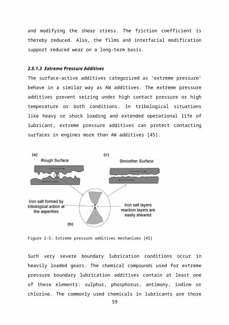
factor in their tribological performances. A material with high reactivity would
more rapidly form oxide films, repair worn spots and re-adsorb surfactant films
under reciprocating sliding contact situation [35].
For ferrous materials, austenitic steel is less reactive than martensitic steel due to
the greater lattice strain of the latter. Steel reactivity also affects oil additive
performance. The phase and alloy concentration of steels are proposed as the
controlling factors in their performance in lubricated sliding. Also, the scuffing load
of ferrous metals is influenced by their microstructure. It is suggested that scuffing
protection for steels cannot be guaranteed with surface hardening. This is because
the induced martensitic phase reduces the ferrite component known for highest
scuffing loads [35].
6. Interaction between Surfactants and Carrier Fluid
Base oils are the carrier fluids for surfactants and additives. Base oils affect the
boundary adsorption lubrication mechanism. Depending on the base oil selected,
the heat of adoption can be high or low. This is related to the friction transition
temperature that affects the formation, destruction and repair of adsorbate films for
lubrication purposes. Bio-based base oils (fatty acids) are amenable to adsorption
lubrication more than mineral oil, due to their polar molecules relatively higher
affinity to metallic surfaces compared with that of mineral oil [35].
3.4.2.3 High Temperature-Medium Load Lubrication Mechanisms
Temperature is a major factor in the lubrication of the piston ring-cylinder liner contact and
in high-speed gears. The two basic high temperature lubrication mechanisms are ‘chain
matching and formation of thick films of soapy or amorphous materials’. The first
mechanism: chain matching describes the improvement of lubricant properties which makes
the chain lengths of the solute fatty acids and those of the solvent hydrocarbon in an oil-based
lubricant equal [35].
Chain matching mechanisms enhance improvements in the scuffing load resistance of
lubricants. This is through the formation of a surface protective thin layer on the contacting
metallic surfaces. The additives may support the bonding of this layer to the surfaces. The
59
protective thin film formation depends on the lubricant additives, and can be effective at
contact pressures higher than 1 GPa, and at temperatures higher than 100oC. In cases where
the chain lengths do not match, a protective thin surface layer cannot form on the contacting
surfaces [35].
The formation of thick films of soapy or amorphous material is the second mechanism. This
is a mechanism dependent on the chemical reaction of lubricant additives with the metallic
surfaces of the sliding tribo-pair. The layer of reaction products can co-exist with the thin
layer formed by the chain matching mechanism. This is an aspect of additives interaction
with metallic tribo-pair surfaces which can affect lubricant film thicknesses, friction and
wear. The thickness of this film is in the range of 100-1,000 nm. The reaction between a fatty
acid and metallic surface leads to the formation of a soapy surface layer within the sliding
contact, more viscous than the lubricant. This viscous layer functions by the hydrodynamic
lubrication mechanisms [35].
The presence of a viscous layer in the tribological interface can be determined by the
electrical contact resistance measurement method. The formation of amorphous layers in
boundary lubrication sliding can be explained by the observation that grinding occurs
simultaneous. Due to this, any object within the contact zone is further reduced in size and
changed in shape. Brittle materials are more likely to shear during this grinding process.
Also, products of additives reactions with the surfaces are subjected to the same grinding
process during sliding. These products of grinding become particles of very small dimensions
that can support load bearing and act as a lubricant. The AW additive zinc
dialkyldithiophosphate (ZDDP) does form amorphous layers in ferrous tribo-pairs [35].
3.4.2.4 High Temperature-High Load Lubrication Mechanisms
In this category of boundary lubrication mechanisms, both high temperature and high load
occur, and lubrication is through sacrificial films. This lubrication mechanism is referred to
as Extreme-Pressure (EP) lubrication. The high load is coupled with sliding speed high
enough for high transient friction temperatures. The high friction temperatures cause
desorption of adsorption films. When the adsorption films are destroyed, sacrificial films
provide the lubrication mechanisms that prevent seizure or scuffing. As explained by
Stachowiak and Batchelor [35], the EP lubrication mechanism through sacrificial films is
influenced by rapid formation of the sacrificial films by a reactive EP additive.
60
Also, the lubrication mechanism is affected by time and the temperature of formation of the
reaction films. During sliding, the oxide films on the asperity peaks are removed by high load
or contact stress. This exposes the bear metals on the contacting surfaces. It is known that
oxide-free metallic surfaces are extremely reactive. The presence of lubricant additives with
sulphur, chlorine or phosphorous enhance the formation of sulphides, chlorides, phosphides
or phosphate films on the metal’s nascent surface. These sacrificial films reduce adhesion
between opposing asperities. The asperities covered by the films are able to relatively slide
with minimum wear, although the inevitable shearing destroys the film material. The ability
of lubricant additives to form sacrificial films repeatedly by reaction with metallic surfaces is
very essential for EP lubrication. The four-ball test is used to determine seizure load
characteristics of a lubricant [35].
3.4.3 Mechanisms of Boundary Lubricating films
The four categories explained in Section 3.4.2 often depend on the formation of boundary
lubricating films. Machinery contacts operating under high load or contact pressure and low
speed conditions require boundary lubrication mechanisms. Highly loaded contacts are found
in bearings, gears, cam and tappet interfaces, piston ring and cylinder liner interfaces, pumps
and transmissions among others. Under boundary lubrication sliding contact conditions, there
are asperity interactions. The frictional heat and metallic reactive surfaces enhance chemical
reactions, including oxidation of the lubricant and the contacting surfaces. The lubricant also
degrades and polymerization occurs, among other reactions [71].
The boundary lubrication films function through several mechanisms as explained by Hsu
and Gates [71]. These include sacrificial layer, low-shear interfacial layer, FM, shear
resistance and load bearing solids. Lubricant base oils are hydrocarbons and equally undergo
several chemical reactions like oxidation, thermal decomposition and polymerization. Since
hydrocarbons oxidize through the free radical mechanism, iron, like other metals,
decomposes hydrocarbons. The boundary lubrication films adsorbed to the metallic surfaces
in contact are formed when hydrocarbons react with oxygen. These chemical reactions
produce polar species like carboxylic acids. The polar species can adsorb to the metal surface,
react with the metal and form metal complexes [72].
61
The chemical reactions induced by relative motion in a loaded contact are studied in
Tribochemistry. The chemical reactions in the boundary lubricated contact follow the
pathway that produce hard, durable, load carrying components, as well as soft polymeric
components. The components of the boundary lubrication film can be formed by
decomposition, reactions between the lubricant additives, base oil and the contacting surface
elements. As temperature is related to frictional transition and adsorption film formation, the
operating temperature in the contact enables the beneficial reactions or otherwise [71].
The appropriate temperature makes the rate of the beneficial reaction products formation to
be more than the rate of desorption or film removal by rubbing. These special chemical
reactions in the sliding contact may be reinforced by wear debris. It is possible to have a self-
repair mechanism under boundary lubricated sliding. This depends on the contact conditions,
the active chemical elements and the environment surrounding the contact area [71].
3.4.4 Tribotest Methods in Boundary Lubrication
Tribotesting can be done in many ways. The configuration one selects would be such that
imitates the machinery or tribosystem contact being investigated. Some tribotest contact
configurations are ball-on-disc with slide and roll combination as used in a minitraction
machine (MTM) tribometer [73], flat-on-flat reciprocating sliding, ball-on-ring, ball-on-flat
reciprocating sliding, pin-on-disc, etc. The factors that affect the results of a tribotest include
the tribo-pair material and surface properties, the tribosystem and its environment.
It is reasonable to consider the cost of testing, test time and control of test conditions. There
are various levels of tribotesting with related degree of realism. Tribotesting can be classified
into tribocouple test, semi-tribocouple test and model test, with decreasing degree of realism
and cost respectively. Tribotest can be open, where the sliding track is renewed continuously,
or closed where the same track is followed continuously by the moving components’ surface
on the fixed component. Also, tribological contact can be conformal or non-conformal as
shown in Figure 3-2. Non-conformal geometries often increase in contact area during testing
with increasing wear, like the case with a ball-on-flat test.
62
Figure 3-8: Tribological contacts (a) Non-conformal and (b) Conformal.
There is frequent need to characterize new materials, lubricants or additives. The constraints
of cost and time necessitate simplification of the tribotest. Tribotest with tribocouple involve
the real components, while semi-tribocouple tests are such that only one of the contacting
surfaces represents the actual component. However, in model tests, the tribo-pair are
simulated [74]. For instance, the piston ring-cylinder liner contact is simulated by a ball-on-
flat reciprocating sliding contact condition.
The behaviours of lubricants and tribo-pairs in the boundary lubrication regime are
investigated with the use of appropriate tribometers. The selection of a tribometer depends on
the tribo-pair geometry and contact conditions. Some common industrial tribometers are the
Shell four-ball machine, the Falex pin-and-vee-block machine, and the Timken extreme
pressure tribometers. These three are designed for industrial applications. The behaviour of
materials under a heavy load and the boundary lubrication regime can be studied using
reciprocating rigs or pin-on-disc tribometer [70, 75].
Boundary lubricated contacts are often partially lubricated or with starved lubrication. In
flooded lubrication conditions, the high contact pressure is such that would ensure that sliding
occurs in the boundary lubrication regime. Laboratory level tribotesting is usually simplified
to a relative motion that best represents the contact situation in real life operation of engines
or machinery. Laboratory-scale lubricant characterisation is common with the ball-on-flat and
pin-on-disc tribometers. These two basic tribometers are well-developed and available. These
two are briefly explained in the following sub-sections.
63
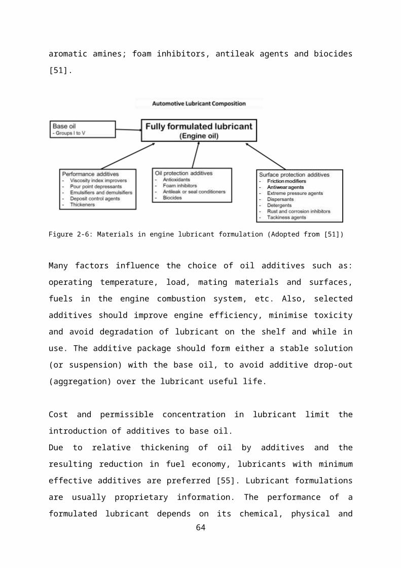
3.4.4.1 The Ball-on-flat HFRR Tribometer
This tribometer is designed to study reciprocating sliding. The high frequency reciprocating
rig HFRR is designed to test lubricant under high frequency sliding conditions. With the
HFRR, the friction and wear being measured reach steady state conditions rapidly, after the
initial transient period of instability. The samples can be manufactured from any material. A
schematic diagram of the ball-on-flat contact is shown in Figure 3-3. There are many
commercially available tribometers with modules for ball-on-flat reciprocating sliding.
Figure 3-9: The ball-on-flat contact
One of the two contact bodies can be reciprocated while the other is held stationary. There is
usually a load system to apply the desired load. The reciprocating ball-on-flat configuration is
adaptable for the piston ring-cylinder liner lubricant testing. The piston ring can be adapted as
the ball, while the cylinder liner is adapted as the flat sample [76]. The Phoenix TE 77 and
the Bruker UMT tribometers have a module for ball-on-flat reciprocating tribotesting. The
tribometers are usually connected to data acquisition systems for monitoring and recording
the evolving friction and wear data for analysis.
3.4.4.2 The Pin-on-disc tribometer
This is a tribometer that is widely used for lubricant characterization in the boundary
lubrication regime. Instead of reciprocating sliding as in the HFRR, it is used to study
lubricant behaviours under unidirectional sliding. The disc rotates while the pin is pressed
against it. The dimensions of the disc and pin depend on the type of tests conducted and the
tribometer. For example, the oil bath of the Bruker UMT tribometer limits the maximum
64
allowable disc diameter. Also, the ball sizes are subject to the diameter of the available ball
holder. The loading system should be such that can give consistent experimental data.
Tribometers are usually connected with data acquisition systems. The Bruker UMT
tribometer has a module for pin-on-disc tribotesting.
3.5 Wear
Wear is usually present in a tribological system along with friction. Wear has been known to
be progressive material degradation subsequent upon the incidence of friction [70]. Wear is
usually evidenced by changes in appearance, geometry, mass or volume of the materials in a
tribological contact. Material degradation in tribological contacts can be by removal or
fracture-induced separation, chemical action or by temperature-activated plastic deformation
at the contact area. In a tribosystem, wear mechanisms are altered by changes in surface
properties, dynamics of the contact, frictional heating, chemical film formation and wear
debris [77].
Wear has economic, material and environmental consequences among others. The costs of
replacement parts and machine downtime are among the economic consequences of wear.
The loss of usefulness of machine parts due to geometrical and surface profile inadequacies
impact on materials and manufacturing costs. The ecosystem bears all the brunt of wear in
that disused machine parts are dumped. Also, in the case of lubricant change, there exists the
possibility of pollution of the water system. Current recycling facilities work to reduce the
impact of wear on environment, although at a cost. Environmentally friendly lubricants are
being developed to reduce waste oil impact on the ecosystem [78].
Wear is a system problem and is more complicated than material property like hardness or
strength. Wear loss depends on the properties of two materials in contact, system loading,
surface properties and the type of motion. Wear can be taken as a system for proper analysis.
There are both, input and output parameters. The input parameters are the type of motion,
contact pressure (dependent on the normal load, contact geometry and surface
characteristics), velocity etc. The outputs from the system are the loss (or gain) parameters
65
which describe the friction and wear behaviour, and the use outputs of system behaviour like
the amount of motion. Thus, the wear behaviour depends on the elements of the system,
properties of materials and surfaces and the interrelationships between the constituent
components of the system [78][79].
The wear rate for a tribological contact is the volume lost from the wearing surface per unit
sliding distance; expressed as m3/m or m2.
The wear rate, w= wear volume ,m3
sliding distance ,m
Wear is classified as either mild or severe. This is not based on any value of the wear rate, but
on general observation of wear transition from mild to severe with increasing load, speed or
temperature. The Archard wear equation provides the basic relationship to explain wear. It
states that the wear rate w is directly proportional to the load W on the contact, but inversely
proportional to the surface hardness H of the softer material in the tribo-pair [70].
The Archard wear equation:
The wear rate, w=K × WH
Equation 3-12Where:
K is the wear coefficient
H is the hardness of the uppermost layer of the softer material in the tribo-pair
W is the applied normal load, N.
The dimensional wear coefficient k which is the ratio K / H is useful in practical situations. It
is usually quoted in mm3 N-1 m-1. This is the wear volume (mm3) per unit sliding distance (m)
per unit normal load (N).
As explained by Williams [70], the broad pattern indicating the interrelationship between
changes in service conditions and material wear behaviour is usually described with wear
mechanisms maps. The mechanisms of wear for rough surfaces are seizure, melt wear,
oxidation-dominated wear, mechanical wear processes such as running-in, adhesive wear,
abrasive wear and delamination wear; fatigue wear in rolling contacts, fretting wear,
corrosive wear, and erosive wear. The mechanical wear mechanisms namely running-in,
adhesive wear, abrasive wear and delamination wear will be explained briefly. This is
66

because, these mechanisms are those common to steel-steel tribo-contacts sliding at velocities
less than 0.1 ms-1. The tribotests in this study belong to this category.
3.5.1 Wear Mechanisms in Sliding
The mechanical wear mechanisms namely running-in, adhesive wear, abrasive wear and
delamination wear will be explained briefly. Tribotest in this study is between steel-steel
sliding contacts at speeds less than 0.1 ms-1. In this case, surface heating is negligible, and
friction tends to deform the contact surfaces, shearing it in the sliding direction. These actions
lead to material removal as wear particles. The wear behaviour follows the Archard wear
equation [70].
In relative motion under load, the forces acting at the interface tend to damage the topmost
surface layers of contacting parts. This results in surface degradation and material loss with
time. As explained by [56], sliding contacts of metallic tribo-couples experience adhesive
wear characterised by high wear rates and large unstable friction coefficient. Strong adhesion
usually occurs when similar materials are combined.
At the early stages of sliding, metallic thin oxide films are removed and this expose bear
metals to direct interfacial contact. Under normal load and relative motion, plastic
deformation between contacting (peak) asperities lead to establishment of true contact. Peak
asperity contact under load and relative motion over time leads to asperity interlocking,
welding, ploughing and shearing [80]. Thus, wear debris are released into the contact. These
may either promote 3-body abrasion or self-heal the contacting surfaces depending on the
situation. Figure 3-4 shows some damage mechanisms that occur in a sliding contact.
67
Figure 3-10: Illustration of the different damage processes activated by a sliding contact [81]
Wear of materials in tribo-contact is known to be influenced by many factors as well as both
material properties and surface characteristics. The lubricant and lubrication system and
temperature will affect wear. Also, the hardness of contacting materials and the contact
pressure affect wear. The severity of wear can range from polishing to delamination and
further increase to scuffing, ploughing, seizure and micromachining. The mechanisms of
wear are revealed by surface examination and microscopy.
3.5.1.1 Running-in
Tribological pairs in the automotive engine are usually mass produced and assembled
together during production or eventual overhaul. At the time of coupling a tribo-pair, the
freshly machined, ground and polished surfaces of the components have asperities that are
conical in shape. It is known that spherical asperities have better load bearing abilities than
conical-shaped ones. The process of initial light load operation of the tribo-pair which helps
to change the conical-shaped asperities to spherical shape is called running-in. During
running-in, the mating tribo-pair surfaces tend to conform, improve in topography and
become more compatible regarding friction [70].
The wear rate is usually high and the wear particles need to be removed by the lubricant from
the sliding contact. Severe wear is usually noticed during the running-in process, as the
processes of adhesive and abrasive wear operates simultaneously. The wear situation turns
from severe to mild wear at the completion of running-in [70]. Running-in occurs in virgin
68
tribo-pairs as sliding begins. In laboratory tribotest, this usually shows as the initial transient
instability in the frictional force data. As sliding progresses the mechanical wear mechanisms,
such as adhesive, abrasive and delamination wear become more prominent depending on the
contact situation.
3.5.1.2 Adhesive Wear
The peak asperities of contacting tribo-pair surfaces usually adhere together due to the
applied load and form junctions. These junctions are then sheared as sliding begins, making
the asperities tips to pluck off from the softer surface and adhere to the harder surface. This is
the model of adhesive wear. As sliding continues, the tips can become detached and be
released to the contact area as wear debris. Lubricants are expected to clean the contact area
of such wear debris, usually into the lubricant (oil) sump of the automotive engine [70].
Two severe damage processes can occur based on the adhesive wear mechanisms, namely
galling and scuffing. Galling is the tearing of macro-scale portion of the contacting surface.
This can be a challenge in sliding situations where the tribo-pair are from similar materials
(e.g. ferrous alloys). Poor lubrication, temperature or high speed can also contribute to
galling. On the other hand, scuffing occurs at the onset of adhesive wear in lubricated contact
when the lubricant film breaks down and can no more separate the tribo-pair surfaces [70].
Adhesive wear mechanisms can be modelled by the Archard wear equation, repeated in
Equation 3-10; but every junction does not contribute to the wear volume. Thus, the wear
coefficient K in Equation 3-10 represents the probability of generating a wear particle.
w=K × WH
Equation 3-13
Thus, the numerical value of K is usually less than 1, although this is not sufficient for some
practical cases. The evidence of adhesive wear would be wear particles with irregular shape
and dimensions that are appropriate to the contact surfaces. The examination of wear particles
give a clue to the mechanisms of their production, but their state may have changed from
when first detached. Wear particles can be further deformed plastically by rolling within the
contacting surfaces and changed by oxidation [70].
69
3.5.1.3 Abrasive Wear
Abrasive wear mechanisms result in damage to tribo-pair surfaces due to either hard
asperities or hard particles trapped within the contact area. There are two types of abrasive
wear, namely 3-body abrasion and 2-body abrasion. The 3-body abrasive wear depends on
hard particles within the contact area; while the 2-body abrasive wear occurs by the action of
a harder surface on a relatively softer surface. The evidence of abrasive wear is a surface with
long parallel grooves, from light scratches to severe gouging. Abrasive wear can be described
by a form of the Archard wear equation as shown in Equation 3-11, where the volumetric
wear loss is proportional to the sliding distance and the intensity of loading. Thus, abrasive
wear resistance is directly proportional to the hardness of the surface of the softer material in
a tribo-pair [70].
The volumetric wear loss, w=K × WH
Equation 3-14
Abrasive wear models assume that deformations occur in the softer surface in a sliding
contact, while the wear of the harder surface is considered negligible. Abrasive wear
involves the indentation of hard asperities into a softer material counterface. The indentation
turns to mild rubbing or severe ploughing due to sliding motion. As described by [70], if the
attack angle of the indenter is more than some critical value, then the wear mode can turn
from rubbing or ploughing to micromachining. Also, the simplified model of abrasive wear
based on the Archard equation propose that rougher surfaces of the softer member of a tribo-
pair would produce larger amount of wear debris. In abrasive wear, some of the materials
removed from the softer surface are detached as debris, while some remain and form
ploughed ridges at the edges of the grooves.
3.5.1.4 Delamination Wear
Delamination wear is a loss of surface material by some other mechanisms different from
adhesion and abrasion, after the initial running-in process. For steel surfaces, delamination
occurs at situations where frictional heating is low, such as sliding at speeds lower than 0.1
m/s. Running-in makes the tribo-pair surface asperities become smoother and more
conformal. After running-in, the frictional force shears the surface layer along the sliding
direction. In this situation, material is lost as thin flakes or platelets [70].
70
Repeated loading, like those in the reciprocating piston ring-cylinder liner contact, has a great
effect on the severity of delamination wear. During sliding, the harder asperities induce
plastic deformation of the softer surface. The deformations accumulate and develop to form
crack at the subsurface near voids or impurities in the bulk material. Delamination begins
with crack nucleation, then propagation to join neighbouring cracks. The connected cracks
then shear to the surface as repeated loading continues, where long and thin wear debris are
removed from the surface. This wear mechanism can also be modelled by the Archard
equation, by assuming the near-surface material contains voids, inclusions or impurities. It is
also assumed that the voids and impurities enhance crack initiation that is the starting point of
delamination [70].
3.6 Lubrication
Lubrication is the process of separation of machine components’ tribological interfaces for
friction and wear reduction and optimal operation of the machinery. The lubricant goes
between two contacting solid bodies in motion to reduce friction and wear. Lubrication can
be dry or wet in a tribological system. Tribological interfaces operating in dry air and at
elevated temperatures require special lubrication mechanisms. Solid lubricants, like graphite,
MoS2, WS2, TiO2, nitrides of boron etc. are used in dry contacts as necessitated by
operational requirements and temperature.
The tribological contact situation and mechanisms of friction and wear in some dry contacts
can allow for adoption of self-lubrication methods [82]. Nanomaterials based on one or more
of the solid lubricants are currently being considered as additives in liquid lubricants. They
are being incorporated in conventional and bio-based liquid lubricants. The lubricating merits
of the parent material are being harnessed, at the nano-scale level, for lubrication purposes.
3.6.1 Lubrication Regimes: Stribeck Curve and Lambda Parameter
Generally, fluid lubricated systems employ liquid lubricants to hydraulically separate the
surfaces in a tribo-pair to reduce friction and wear. In cases where the contacting surfaces are
completely separated by a film of lubricant, it is referred to as hydrodynamic lubrication.
Here, the film of lubricant is built within the contact zone through motion. When the
contacting surfaces are not completely covered by the lubricant film, there occur asperities
71
interactions. This is the mixed lubrication regime, also called elasto-hydrodynamic
lubrication regime. Further reduction in the lubricant film available in the contact zone leads
to a dominance of asperity contact. The means of surface separation would be through
physically or chemically absorbed boundary lubricant film. This is the boundary lubrication
regime [42].
Fluid lubricated systems are conventionally characterised by the Stribeck curve shown in
Figure 3-5 as explained by Woydt [83]. The Stribeck curve is a plot of the coefficient of
friction against the Hersey number. The Hersey number is a dimensionless number expressed
as the product of viscosity, η and the rotational speed, N, RPM, divided by the average
pressure, P, N/m2. The average pressure, P = load/projected area.
Hersey Number=η . NP
Equation 3-15
Although this does not account for the influence of additives in the lubricant, especially NPs,
it is still an acceptable basis for lubrication analysis. The three categories of fluid lubrication
or friction regimes, based on the Stribeck curve [83] are:
(i) Boundary lubrication (BL),
(ii) Mixed lubrication (ML),
(iii) Fluid, full film or hydrodynamic lubrication (HL).
The Stribeck curve stemmed from carefully conducted, wide ranging series of experiments on
journal bearings. The graphs clearly showed the minimum value of friction (coefficient) now
known as the transition between full fluid-film lubrication and some solid asperity
interactions. Functionally speaking, based on the Stribeck curve, the coefficient of friction
depends on the dimensionless product of sliding speed and viscosity divided by the contact
pressure.
72

Figure 3-11: Characterisation of friction regimes according to the Stribeck curve in conformal contacts [83]
Figure 3-12: Classification of lubrication regimes based on lambda parameter in non-conformal contacts [84]
The Lambda parameter, λ, shown in the Stribeck curve (Figure 3-5) is further explained in
Figure 3-6 by Kalin [84]. The lambda parameter is used to determine the lubrication regimes.
This demonstrates the relative magnitude of friction coefficient, and the ability of a lubricant
to separate the contacting surfaces. The lambda parameter was designed to determine the
effect of the contact conditions on the lifetime of a tribo-pair. Thus, a more precise
classification also includes λ ≥ 4 for fully elasto-hydrodynamic lubrication (EHL), with no
effects on wear.
The mixed-lubrication regime is also divided up, from 1 to 1.5; and from 1.5 to 3. These
indicate the different influences of friction on wear. The lubricant presence or otherwise,
impacts the wear behaviour of a lubricated system. As well, surface roughness impacts highly
on lubrication of surfaces if lubricant film thickness is of the same order as the roughness
[85]. The relationship between the dimensionless film parameter, λ, and the minimum film
thickness, ho, is expressed as:
73
Lambda, λ = ho
√RqA2 +RqB
2
Figure 3-10Where, ho minimum fluid film thickness
RqA RMS surface roughness of body ‘A’
RqB RMS surface roughness of body ‘B’
Typically, the four lubrication regimes [86], based on lambda are identified and described as
follows;
(i) Hydrodynamic lubrication: 5 < λ < 100
(ii) Elasto-hydrodynamic lubrication: 3 < λ < 10
(iii) Partial or mixed lubrication: 1 < λ < 5
(iv) Boundary lubrication: λ < 1
Full separation between asperities in the contact zone would avoid direct metal-to-metal
contact. Lubricant film thickness should be above the critical ho, for needed separation of
interfacial peak asperities. The Lambda values are rough estimates, and running-in is known
to affect the film parameter. Lambda increases with running-in, as the combined surface
roughness will decrease. With running-in, the peaks of the asperities become more spherical
(from conical), and flattens.
Automotive engine lubricants should provide adequate lubrication performance in all the
regimes of lubrication. This is because some engine components undergo all the regimes of
lubrication during operation. Metal-metal contact can take place at low speeds and high
loads, especially with low viscosity lubricants. This is the case with the piston ring-cylinder
liner sliding in the mixed or boundary lubrication regime. In this condition, surface contact
occurs and chemical films or reaction products are essential for surface protection [3].
3.7 Boundary Lubrication of the Piston Ring-Cylinder Liner Contact
The effectiveness of lubricants in engine operations under boundary lubrication conditions is
very important. This becomes more essential with increasing demand for improvements in
energy or fuel efficiency and the availability of new materials and additive packages. In a
lubricated automotive engine contact, there are operational situations like cold start and top
74
dead centre position, when the average lubricant film thickness becomes lower than the
average relative surface roughness. During such an instance, surface contact and surface
chemical films should support the applied load (see Figure 3-7). Due to lubricant starvation, it
would seem as though the contact is dry [87].
Surface asperities’ interactions would produce abrasion, adhesion, deformation, fatigue and
other forms of wear. The presence of small amounts of the lubricant provides a supply of its
molecules that react chemically with the contacting surface asperities. This reaction is often
enhanced by frictional heating in the sliding contact. Thus, a tribofilm would be formed on
the contacting surfaces, which may either be beneficial or not. The tribofilm formation that
supports load bearing or sharing by the asperities in a sliding contact constitutes the
boundary lubrication regime [87].
Figure 3-13: Boundary and other lubrication regimes in relation to contact severity, load bearing mechanisms
and coefficient of friction [87].
Boundary lubrication (BL) occurs in the operation of the piston ring-cylinder liner contact, at
the most heavily loaded tribo-contacts especially at ‘near top ring reversals’ or similar, due to
compression and combustion [88, 89]. The performance of automotive contacts is most
critical at moments when sliding surfaces experience peak asperity contacts. It has been
75
observed [3] that different automotive contacts and components require different lubrication
regimes for optimal performance. The piston ring-cylinder liner contact is about the most
complicated tribological contact; due to large variations of load, speed, temperature and
lubricant availability.
This contact experiences transitions between the boundary, mixed and hydrodynamic
lubrication regimes during a single stroke; and displays highest friction coefficient at the top
and bottom dead centres (TDC and BDC). It is observed that asperity-asperity interactions
are predominant at these points [76], i.e. at the crank angles of 0 and 180o, as shown in
Figure 3-8. Thus, the boundary lubrication regime with the incidence of peak asperity
contacts is the most critical in the ring-liner tribo-contact.
Figure 3-14: Lubrication regimes during an expansion stroke [76]
Friction and wear improvements in the BL regime may rub off positively on other lubrication
regimes. For instance, in a piston ring-cylinder liner tribotest of one fully formulated engine
oil mixed with 0.25 wt% Al2O3, the COF reduction is in the range of 48-50% for the BL
regime; while it is 33-44% and 9-13% for the mixed and hydrodynamic lubrication regimes,
respectively [90].
76
(a) Piston assembly (b) Piston ring operation
Figure 3-15: Piston rings and their functions in an internal combustion engine [3]
The piston assembly is critical in transforming the energy generated by fuel combustion into
kinetic energy. As explained by [3], the piston assembly (see Figure 3-9) consists of the
machine elements that form the piston ring-cylinder liner contact in the engine. These include
a series of rings which function firstly to maintain an effective gas seal between the
combustion chamber and the crankcase. Secondly, piston rings transfer heat from the piston
into the cylinder wall, and into the coolant. Thirdly, piston rings minimise oil inflow into the
combustion chamber from the crankcase.
This entry of lubricant into the combustion chamber is a large contributor to engine oil
consumption. The burning of oil and fuel mixtures leads to exhaust of harmful emissions. The
schematic representation of an internal combustion engine piston assembly is shown in
Figure 3-9 (a). The piston has an upper region with grooves for holding the rings and the
region below the ring pack called the piston skirt. The piston skirt transmits the transverse
loads on the piston to the cylinder wall. The ring pack consists of three rings: two
compression rings and one oil-control ring [3].
As shown in Figure 3-9 (b), the top (1st) compression ring is the major gas seal and has the
highest load and temperature during engine operation. It is the ring closest to the combustion
chamber. The firing pressure acts on this ring until it engages the cylinder wall. Also, gas
pressure during compression stroke, keeps the ring in contact with the cylinder wall
maintaining an effective combustion chamber seal. It usually has a barrel-faced profile with a
wear resistant coating [3].
77
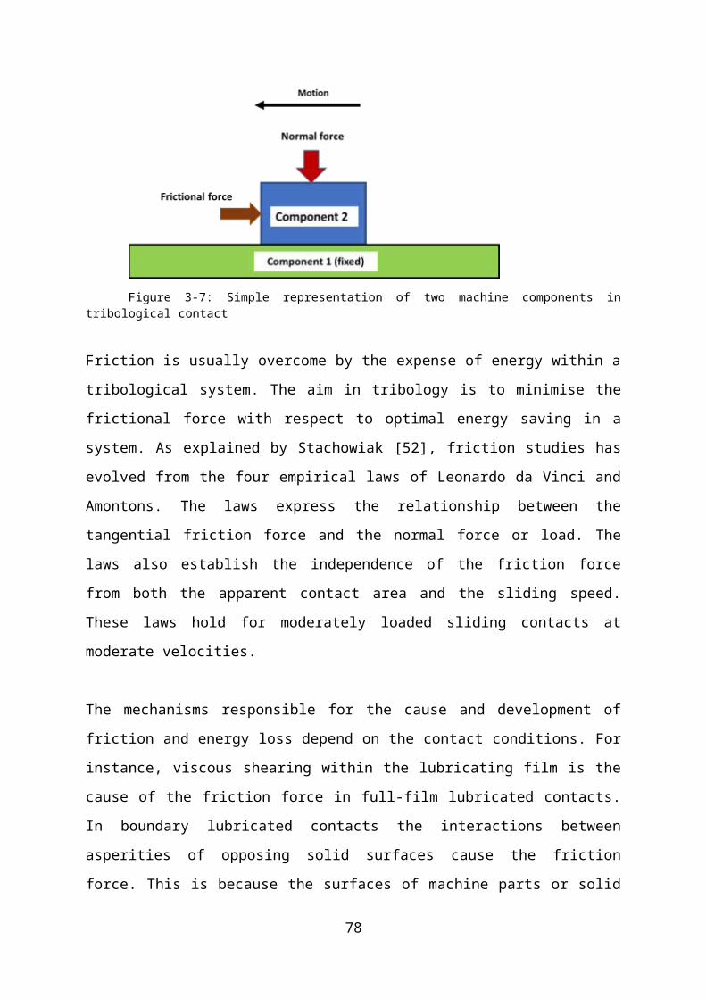
The second piston compression ring is often called the scrapper ring. It is designed to reduce
the flow of oil to the combustion chamber, and act as a secondary gas seal. It has a taper-
faced scrapping profile, for scrapping surplus oil from the cylinder walls. The bottom ring has
two running faces or lands and a spring element for radial load. It serves to minimise oil entry
from the crankcase into the combustion chamber. The piston ring experience large variations
of load, speed, temperature and lubricant availability [3].
The materials and surface finish of piston rings and cylinders are important to the friction and
wear behaviours of their sliding interface. Steel is used for the top compression rings and the
rails of multi-piece oil control rings. This is due to high strength and fatigue properties. Some
of the wear resistant coatings are chromium plating, flame sprayed molybdenum, and plasma
sprayed molybdenum, metal matrix composites, cermet and ceramics [3].
Cylinder liners are manufactured from grey cast iron, either plain or with alloy elements
added. Surface finishing techniques apply to the piston assembly with the aim to improve oil
retention, minimise scuffing and promote ring profile formation during running-in. Cylinder
bores or liners surface finishing techniques include: honing with ceramic stones, diamond
hones, rubber tools and cork tools. The steel piston rings could have their oil wettability
enhanced by etching, grit blasting and lapping [3].
The lubricant tribotesting in this study adopted two tribometers, the ball-on-flat HFRR and
the pin-on-disc module on the Bruker UMT. The ball and pin samples are of AISI 52100 steel
materials; while the flat and disc samples are machined from EN-GL-250 grey cast iron. The
piston ring-cylinder liner engine contact is represented by the reciprocating ball-on-flat
tribotest configuration. This is bi-directional as is the situation in the automotive engine.
However, the pin-on-disc tribotest configuration is unidirectional for general friction and
wear characterisation of lubricant and additives.
3.8 Conclusions
Tribology and its basic constituents have been discussed briefly in this chapter. The
observations of friction and wear behaviours and lubrication performance of materials would
readily be evidenced on the contacting surfaces. This makes the surface very important in
78
tribological studies, from basic surface profile before and after tribotesting; to wear surface
characterisation with high level microscopes.
Friction was briefly explained and the goal of tribology is to minimise the coefficient of
friction in the automotive engine contact of interest. This would minimise the expense of
energy, which could lead to fuel savings. The theories of friction dovetailed to those of wear.
This is because wear is usually a direct consequence of friction. The loss of material occurs
over time of engine operation, leading to geometrical inaccuracies, vibration, noise and
emission of combustion products. Wear mechanisms such as running-in, adhesive wear,
abrasive wear and delamination wear were described as those interacting in a boundary
lubricated sliding contact.
The boundary lubrication regime occurs in the piston ring-cylinder liner contact when
asperity peaks come into contact during engine operation. The theory and categories of
boundary lubrication were briefly explained. One of the main lubrication mechanisms in
boundary lubrication sliding conditions is tribofilm formation. This is mainly through the
action of the lubricant and additives on the metallic contacting surfaces. The tribofilm
formation processes are affected by temperature, contact pressure and chemical reactions at
the tribological interface. The lubricant additives are major contributors to tribofilm
formation in boundary lubrication sliding, especially of ferrous metallic pairs.
Tribotesting in the boundary lubrication sliding conditions in this study adopted the HFRR
and the UMT pin-on-disc tribometers. These were briefly described. Their details are
presented in the methods sections. Lubrication is meant to mitigate friction and its
consequence, wear. The Stribeck curve gives the categorisation of lubrication regimes. Also,
the Lambda parameter is used to assure that tribological system runs at the required
lubrication regime. These were described in relation to the piston ring-cylinder liner contact
which could experience all the regimes of lubrication in a single stroke of operation.
The first compression ring is the most critical in engine operation. It experiences the most
severe forms of contact pressure, friction and wear. Thus, minimising friction and wear in
this contact would lead to significant energy or fuel savings and material savings. The next
chapter is a review of some NPs additives with potentials for friction and wear reduction in
79
automotive contacts. They are usually utilized alone or in combination with conventional
additives.
4 Nanoparticles Lubricant Additives
80
Nanoparticles are emerging lubricant additives with friction and wear reduction potentials.
This chapter introduces NPs and their properties relevant to fluid lubrication. Some earlier
work regarding their additions to mineral oil, paraffinic oil, poly alpha olefin and rapeseed oil
are briefly described. The Polyvit NPs system is then introduced as a potential additive for
biolubricants.
4.2 Properties of Nanoparticles in Tribology
Developments in the processing of various inorganic materials (e.g. aluminium oxides,
silicon carbides, graphite) have led to particles with at least one dimension between 1 × 10 -9
m and 1 × 10⁻⁷ m, known as NPs, becoming relatively commonplace in science and
engineering. The effective 100 nm limit exists because many of the defining characteristics of
NPs change when particles are greater than this size. NPs can exist in spherical, rod, plate-
like and other shapes. They have a larger surface area to volume ratio than their bulk (larger-
sized) material leading to the surface properties dominating the bulk properties.
When NPs are mixed with liquids, colloids are formed. Colloids should be stable during their
use in machinery for lubrication purposes. It has been observed that the mechanical properties
of NPs can affect the tribological behaviour of lubricants with NPs additives. For example,
the hardness of NPs, compared to that of the lubricated sliding contact interfaces, would
influence the behaviour of NPs. When the contact pressure is high, the NPs may deform or
indent into the surface. Also, NPs could be used as abrasives in the nanopolish of highly
smooth surfaces [91].
The hardness and elastic modulus of NPs are different from those of their bulk materials,
depending on size. The spherical NPs of gold (Au), silver (Ag) and Silicon (Si) are reported
to exhibit such size-dependent behaviours. Both hardness and elastic modulus increase with
decreasing particle size [91], as shown in Table 4-1. Generally, a metal oxide has higher
hardness than its pure metal, for example, large size or NPs of silica (SiO2) have higher
hardness than that of silicon.
Table 4-2: Size-dependent Hardness and Elastic Moduli of Gold, Silver and Silicon. Adapted from [91].
Material Diameter, nm
Hardness, GPa Elastic modulus, GPa
NPs Bulk, HV NPs Bulk
81

Gold (Au) 22 1.72 0.216 100 79Silver (Ag) 13 3.12 0.251 103 83Silicon (Si) 5-40 20-50 12 600 150
The factors responsible for NPs’ higher hardness when compared to their bulk materials
include: dislocations inside the particle, changes in the lattice strain and bond energies with
respect to the compressive stress. These factors make crystalline metallic NPs resist high
pressures. Along with hardness of NPs, adhesion and friction are factors affecting their
lubrication and colloidal stabilization characteristics among others. The adhesion between
NPs in aqueous media is influenced by the van der Walls force and more effects beyond
continuum theories [91].
The friction force at the nanoscale is different from established friction laws for contacts of
macroscale solid bodies. Also, the nanoscale friction varies directly as the true contact area
and not necessarily proportional to the applied load [91]. The shape and size in relation to the
surface roughness of the sliding interface are also observed by Reeves [92] to influence the
tribological behaviour of NPs. All these factors clearly have roles in the mechanisms of
lubrication by NPs additives.
4.3 Lubrication Mechanisms of Nanoparticles in Lubricants
NPs that can be used as additives in lubricating oil include carbon and its derivatives,
sulphides, nanocomposites, metals, metal oxides, and rare earth materials. The lubrication of
metallic tribo-pairs with NPs additives in lubricants is dependent on several characteristics of
the NPs.
As explained by Dai [93], the key characteristics include the particle size, shape and the
chemical composition of NPs. The NPs characteristic size of less than 100 nm allows them
easy entry into the tribo-pair interface for lubrication. This entry or the feeding effect makes
smaller NPs penetrate tribo-pair interface better than larger ones. Also, the high surface-to-
volume ratio of NPs enhances chemical reactions with their surrounding environment, which
supports reduction in the coefficient of friction. Thus, size, shape and aspect ratio influence
friction reduction and AW performance in a similar manner.
82
The effects of chemical compositions of NPs and their interaction with lubricating oil and
tribo-pair surfaces have also been studied by Dai and co-workers [93]. Molecular structures
(sheet, tube, onion) dominate the tribological behaviour of carbon-based NPs. Also,
tribofilms formation on metallic surfaces play important roles in the tribological performance
of sulphides like MoS2, WS2, rare earth compounds etc. However, the tribological
performance of nanocomposites, like SiO2, is enhanced by the change of their surface
properties from hydrophilic to lipophilic. Three lubricating mechanisms of NPs in lubricant
are proposed as follows: firstly, metallic and metallic oxides NPs can form adsorption films
on tribo-pair surfaces; secondly, NPs can roll between two sliding surfaces; and thirdly, NPs
can fill wear track and undergo sintering by frictional heat and pressure.
Generally, rolling, sliding and tribofilm formation are the main mechanisms of NPs in
lubricant. Tribo-pairs lubricated by NPs in lubricant experience one or more of these modes
for friction and wear reduction. As explained by Dan [91], the rolling mode is influenced by
the interplay between the shape, size, hardness, elastic modulus and concentration of the NPs
in the lubricant. The preservation of the spherical shape observed with high lubrication
performance by Dai [93] depends on the size and hardness of the NPs.
However, the sliding mode occurs in NPs which are not spherical and with low adhesion to
the mating surfaces. Sliding is supported by agglomeration of NPs in the contact area, contact
pressure, tribo-pair materials hardness and interaction forces between NPs. In the sliding
mode, tribofilms formation can be due to delamination of NPs under very high contact
pressure. Dan [91] suggested that when contact pressure is about 1 GPa, the tribo-pair
operates in the boundary lubrication regime. In this contact condition, mechanically sheared
NPs can form as third bodies and adhere on the mating surfaces, separating them from
interference.
Lee [94] proposed the four possible lubrication mechanisms shown in Figure 4-1 for NPs
namely: rolling, protecting, mending (or healing) and polishing. In agreement with these
mechanisms, Battez [95] and Dai [91] observed that the friction modification and tribofilm
formation of NPs can be as results of third body and tribo-sintering mechanisms. Tribo-
sintering can be expressed as the coalescence of in asperity valleys and fusion of NPs to form
83
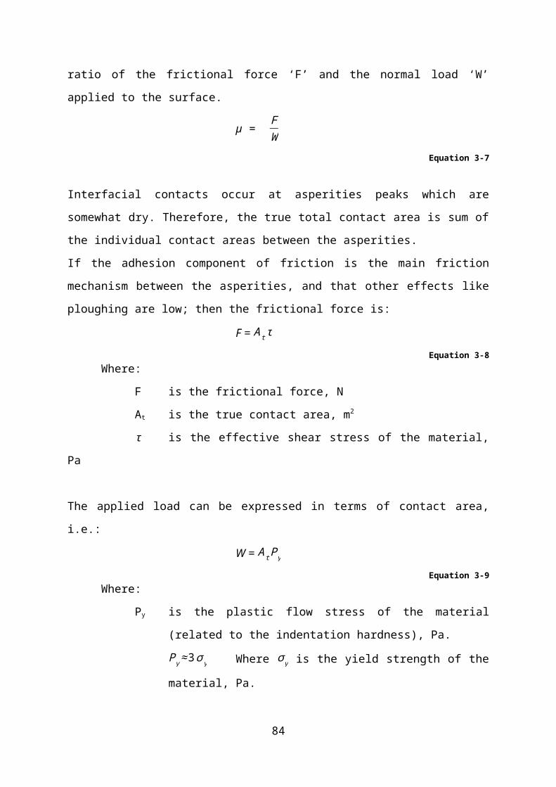
films or layers during relative motion in loaded interfaces. Sintering occurs at elevated
temperatures with NPs fused into denser materials [96].
Relative sliding under high contact pressure usually experience flash temperature rises as
asperities peak interact. As explained by Kato and Komai [97], sliding contact temperature
rise above RT is sufficient to support tribo-sintering. As shown in Figure 4-1 (b) and (c),
particle size should allow for entry into asperity valleys. Although in the works of Kato and
Komai, NPs were supplied dry to dry contacts, lubricated contacts could also have supply of
NPs as lubricant additives. The lubricant would serve as the means of transporting the NPs to
the tribo-pair interfacial contact.
Figure 4-16: Possible lubrication mechanisms NPs in a lubricant [94]
Luo [98] reported that NPs in oil form self-laminating protective films on tribo-surfaces,
turning sliding to rolling friction as shown in Figure 4-1 (a). Some carbon-based NPs, as
platelets, tubes and fibres can improve lubricating performance of lubricants. Eswariah [99]
observed the that the nanoscale modified graphene platelets (MGPs) act as nanobearings
between tribo-couples. Also, carbon nanotubes (CNTs) and carbon nanofibers (CNFs) could
fill the micro-gap of tribo-contacts, thereby forming self-assembly of lubricating thin films.
These are the mending or healing and protective effects shown in Figure 4-1 (b) and (c)
respectively.
NPs of self-lubricating materials like MoS2, WS2, BN, graphite etc. have been reported to
exhibit similar solid lubricant properties of their larger scale equivalents [27]. As well, there
exists the issue of optimal concentration of NPs dispersed in oil. As reported by Jiao [100],
although Al2O3/SiO2 hybrid NPs reduce the coefficient of friction (COF) due to the slide-to-
84
roll effect at optimal concentration, this turns to polishing (see Figure 4-1 (d)), when particle
concentration becomes too high. As observed by Dan [91] high concentration of NPs in
lubricant can increase COF, abrasive wear and heavy aggregations. In essence, NPs can
either be employed for tribo-film formation or as surface modification tool for lubricated
machine surfaces [94].
The interactions between factors like the size, shape, and other features of the NPs supplied
to the tribo-contact is essential. These factors relate fairly with surface profile parameters; Ra,
Rq, and the combined surface roughness. Reeves [92] observed that NPs additives lubrication
performance is influenced by particle size, particle shape and the tribo-couple’s combined
surface roughness. The smaller the NP size the more spherical the shape.
When the surface roughness is made of the same order as the NP size, the performance is
highly enhanced. For instance, in a copper-aluminium pin-on-disk test under ambient
conditions [92], the 5 wt. % 70 nm NPs in canola oil and flat surface roughness of 0.27 µm
enhanced the formation of boundary lubricating films that lowered friction and wear. This is
because unlike larger sized particles, the small spherical particles coalesced in the asperity
valleys for tribofilm formation.
However, the surface roughness has low effects on the oil-ZDDP-NPs mixture lubricating
performance. Aldana [101] observed that base oil mixed with zinc dialkyldithiophosphate
(ZDDP) and WS2 NPs, size 50-130 nm, and tested in a steel-steel reciprocating pin-on-flat
tribometer have the same value of COF, lower wear trend. Also, tribofilm formation were
obtained with both smooth [16] (Ra = 0.06 µm) and rough [101] (Ra = 0.3 µm) surfaces.
Kogovsek [102] also observed that surface roughness has low effects on friction. He observed
that within the surface roughness range: 0.006 ≤ Ra ≤ 0.040 µm: NPs size, shape and structure
control the tribological behaviour of contacts.
4.4 Nanoparticle Additives – Some Earlier Works
NPs can be employed to improve lubrication and performance characteristics of tribo-systems
where fluids separate the surfaces. These include lubricants and fuels. Fuel injection systems
– pumps, nozzles, etc. may exhibit improved tribology performance with NPs. Nanomaterial
fuel application seems as a ‘green’ field awaiting exploration. For example, doping diesel
85
with alumina NPs have been reported [103] to offer ‘substantial enhancement in the brake
thermal efficiency and a marginal reduction in harmful pollutants - NOx, CO and smoke’
compared to conventional diesel.
The piston ring-cylinder liner contact could experience boundary, mixed and hydrodynamic
lubrication regimes during a single stroke. But the boundary lubrication regime seems most
critical with the incidence of asperities contact during sliding at room and high temperatures.
The earlier studies on lubricant-NPs tribology in the boundary lubrication regime are
considered more relevant to this study than others. Some NPs’ lubricant and fuel additivities
as observed by researchers are presented as follows.
4.4.1 Nanoscale Additives in Mineral Oil
Many researchers have investigated the use of NPs additives in mineral oil in automotive
engine lubrication. Some were at the laboratory level while some were field tests in real life
internal combustion engines. The tribological properties of modified graphene platelets
(MGP) NPs in mineral oil were investigated in a four-ball tribometer [104]. At the optimal
conc of 0.075 wt%, both the wear rate and COF are lower for the oil with MGP than those
without MGP. The SEM and EDS analyses of the rubbing surfaces confirmed the presence of
a continuous protective films formed by the carbon (C) element in the graphene (MGP)
[104]. This is an indication that the carbon element from the graphene MGP) formed a layer
on the rubbing surfaces for COF and wear reductions. The mechanism of lubrication is
tribofilm formation and this occurs at a low concentration of the NPs.
A nanofluid of ZnO NPs in light paraffinic oil was tested for tribological characteristics. The
average particle size of the ZnO NPs is in the range of 40 to 100 nm. An optimal
ultrasonication time of 30 min was observed to correspond with the highest COF reduction by
20.37%. An optimal ZnO NPs concentration of 2 wt.% was observed with the lowest COF
and wear volume loss. The initial Ra of the test surfaces of 25 nm gave the best COF
reduction, compared to that from test surfaces with Ra of 100 nm and 250 nm respectively.
Also, the wear track widths were larger with the NPs additives, compared to samples tested
without NPs additives [105].
The surface chemical analysis showed that Zn deposition on the wear track was higher
without a surfactant, compared to when surfactant was used. It was observed that the ZnO
86
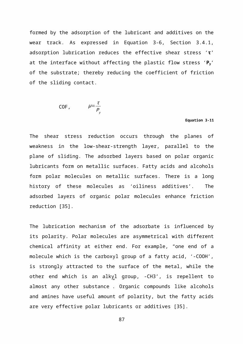
NPs supported COF reduction in the tribo-pair at low velocity sliding. This advantage
becomes lost as the sliding speed increased beyond 500 mm/s. Also, at low loads of 5 and 10
N, lower wear volume loss occurred, compared to higher loads of 20 and 30 N, respectively.
The study proposed the lubricating action mechanisms of the ZnO NPs as being more of
nano-ball bearings between the sliding tribo-pairs, than tribofilms formation on the contacting
surfaces [105].
The use of surfactants does not improve the lubricating performance of ZnO NPs in paraffinic
lubricant. Also, the normal load on the tribo-pair should be low, about 5 or 10 N for low wear
volume loss and ability to view the element deposit on the wear surface. The surface
roughness of the disc should be relatively low, about 0.025 μm as this impact positively on
the tribological performance of the tribo-pair. The rolling effect, also referred to as the nano-
ball bearings lubricating mechanism is explained by Gulzar [106] as illustrated in Figure 4-2.
As in the work of Gara [105], the NP-based nano-ball bearings could be viewed on the wear
surface and their chemistry analysed.
Figure 4-17: Schematic of the ball-bearing lubricating mechanism by NPs in a lubricant [106]
Peng [107] observed the effects of SiO2 NPs in paraffin lubricant using a ball-on-ring
tribometer. Large-size particles over 1-2 µm would agglomerate more than smaller-sized
NPs. The optimal additive concentration for SiO2 in a lubricant is proposed to be between
0.05 and 0.5 wt.%. The SiO2 NPs could either enter the asperity valleys or form thin
tribofilms on the rubbing surfaces. This is evidenced by the SEM/EDS spectrum showing the
presence of Si element on the wear scar. The boundary lubricating films support load and
separates the sliding surfaces leading to lower wear and COF respectively.
87
The spherical shape of the NPs allow for transition from sliding to rolling friction at the tribo-
pair interface. Thus, ball-bearing and surface polishing by SiO2 NPs are the dominant friction
and wear reduction mechanisms. While the ball-bearing mechanism could reduce COF and
wear, the polishing mechanisms would increase wear. The polishing mechanisms is usually
associated with higher than optimal concentration of NPs [100].
4.4.2 Nanoparticle Additives in Poly alpha olefin
NPs of some materials could be useful as green additives to lubricants; these include MoS2,
WS2 NPs in various forms, sizes and shapes. Some workers have reported tribological
performance improvements when NPs are added to the synthetic lubricating oil, poly alpha
olefin [88, 102, 108-114].
Rosentsveig and co-workers [111] mixed inorganic fullerene-like MoS2 (IF-MoS2) NPs with
poly alpha olefin (PAO) oil of two viscosities within the range encountered in engine
lubrication. They observed that the size and crystalline order of the IF-MoS2 NPs affect its
tribological performance. Using the reciprocating ball-on-flat and steel-steel tribo-couple at
RT only, they observed that the contact pressure does not affect the COF reduction
characteristics of the NPs. The addition of 1 wt% IF-MoS2 lowered the COF compared with
pure PAO oil, under boundary lubrication sliding conditions.
As earlier observed, IF-MoS2 NPs [111] exhibit lubricating mechanisms similar to those of
silica NPs. Spherical-shaped and smaller-sized NPs enter into valleys on the rubbing surfaces
and form fused layers (tribo-sintering). The tribofilms formed by tribo-sintering contribute to
COF reduction. However, larger NPs which could not enter the contact area would gradually
exfoliate. They then form molecular sheets that become transferred onto the asperities of the
surfaces as third bodies.
In the work of Kalin [110], a ball-on-disc tribometer was used for the characterisation of the
tribological behaviour of MoS2 multi-wall nanotubes (MNWNTs) additives in PAO. The
nanotubes have a range of 100-500 nm in diameter. The MNWNTs were mixed with PAO at
a large concentration of 5 wt% to make their effects easily noticeable. The oil-NPs
suspension was mixed with ultrasound and re-agitated for 1 hr before tribotesting. The oil
was tested in a steel-steel ball-on-disc tribometer. An initial Hertzian contact pressure of 700
88
MPa was used with a velocity of 0.0005 m/s. The addition of MoS2 multi-wall nanotubes
reduced the COF from 0.16 for PAO only to 0.07 for PAO with the nanotubes.
Figure 4-18: Model showing NP entry into the valleys on the contacting surfaces. Valleys on the surface
(profile) act as reservoirs and help to preserve the NPs within the contact [110].
Figure 4-19: Illustration of two types of MoS2 protective tribofilms: (a) thin film, based on individual nanosheet
that exfoliates; and (b) thick film, composed of aggregates separating interfacial contact [110]. (Sliding direction
is perpendicular to the plane of the image)
The SEM/EDX analyses showed the presence of the elements of the nanotubes, Mo and S, on
the wear scar. Thus, the formation of tribofilm is important to friction and wears loss
reduction. One of the mechanisms of lubrication by the nanotubes is schematically illustrated
in Figure 4-3, where nanotubes fill up the valleys of the surface asperities and cause an
increase in the real contact area. Also, the valleys could act as microscopic reservoirs for the
nanotubes or NPs. Smaller sizes are better than larger sizes NPs for these mechanisms.
Another possible lubrication mechanism is the exfoliation of the nanotubes to form load
supporting layers on the contacting surfaces [110], as shown in Figure 4-4.
The nanotubes exfoliate under shear stress, deform, compact, smear on the contacting
surfaces and tear apart for further exfoliation. The slide-to-roll mechanism is not likely to
occur in the boundary lubrication regime with the nanotubes additives. This is due to their
deformability, broad size distribution and structural defects. Also, the tribofilms on the wear
surface are preserved by lightly rinsing the disc sample in high-purity benzene with
89
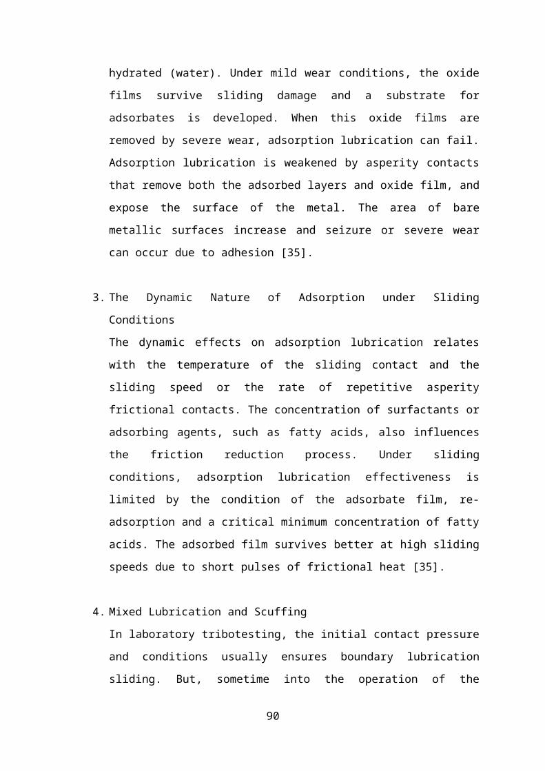
ultrasound for a short time, 10 s [110]. Thus, the low contact pressure preserved the wear
surface from heavy damage and careful rinsing removed lubricant from the wear surface
while preserving the tribofilms.
4.4.3 Nanoparticle Additives in Rapeseed Oil
NPs of CuO has been observed to have potentials as AW additives in a chemically modified
rapeseed oil tested in HFRR under boundary lubrication conditions [13].
The CuO NPs used has a size range of 40-70 nm with spherical shape, such that at 0.5 wt. %,
the COF reduces by 27% compared with lubricant without the NPs. As usual with NPs, the
slide-to-roll mechanism is observed with the CuO NPs.
Also, the CuO NPs fill deep cavities, voids and cracks to form tribofilms. These are the
mending, renovation or self-healing mechanisms. However, higher concentration of NPs in
the lubricant causes more solid-solid contact, thus increasing wear. The flat sample lubricated
with the lubricant-NPs mixture have lesser grooves, pits, cavities and material transfer
compared to those with the bare lubricant. So, under boundary lubricated sliding, CuO NPs
have potentials as AW additives in the chemically modified rapeseed oil [13].
4.5 Nanoparticle Additives and the Polyvit
Polyvit (as supplied by industry) is a hybrid NPs system with three constituents, namely:.
Hybrids are known to present optimal combination of desired performance characteristics of
more than one material. Some studies have been reported on the use of alumina, silica and
graphite NPs as lubricant additives. Nanomaterials of each of them have been observed to
offer tribological merits. Also, some synergies have been suggested between hybrids of any
two of these three. This study is the first to consider the Polyvit as additives in a biolubricant.
The performance advantages of each of alumina (Al2O3), silica (SiO2) and graphite (from
Carbon, C); and different hybrids of any two are briefly presented. Most of these earlier
studies are on ferrous metals in the tribo-contact. These give some guides and insights to
likely outcomes of this study.
4.5.1 Nano-alumina Particles Additives
Alumna NPs alone and in combination with other NPs have been investigated with potentials
for tribological improvements in lubricants and fuels [98, 115-121]. Mahbubul and co-
90
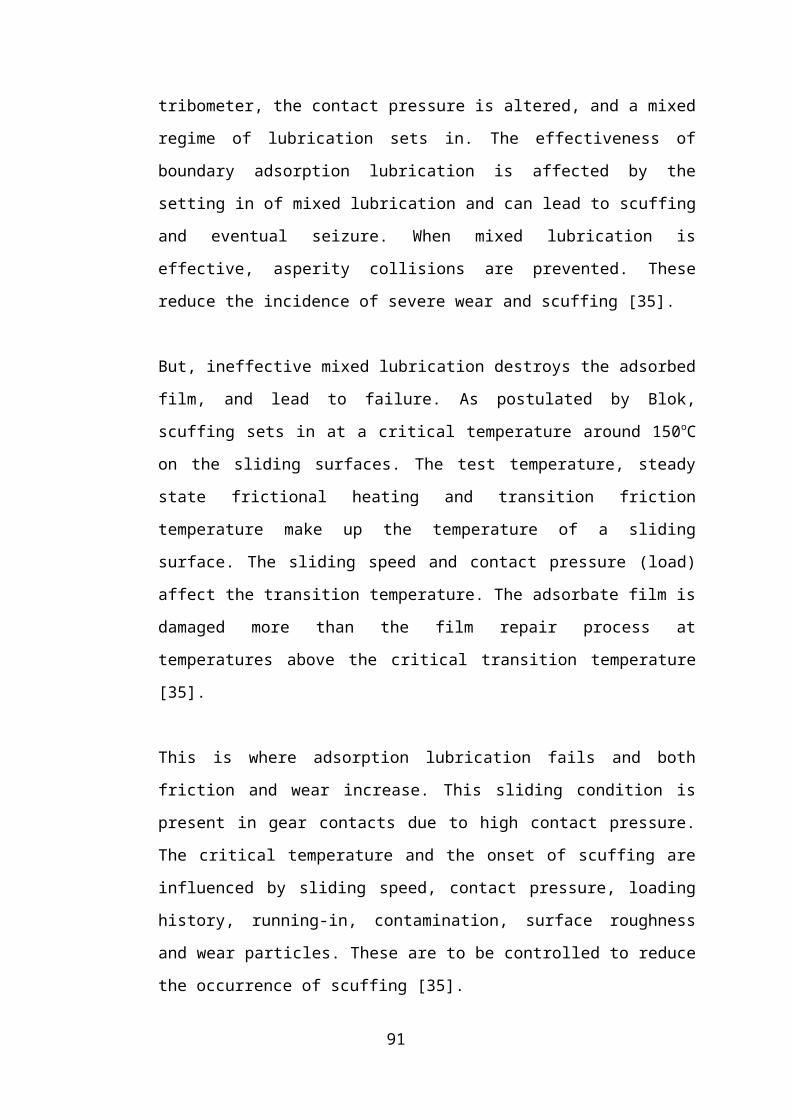
workers [122] observed that alumina (Al2O3) NP has the following qualities: easy dispersal in
most fluids, inexpensive, easy to manufacture in large scale, spherical shape in most cases
and aspect ratio of about one (The aspect ratio of a particle is the proportion of its width to
height). Ultra-sonication for about 60 minutes is reported as necessary to ensure proper
dispersal of alumina in water; this can affect the colloid viscosity.
In a pin-on-disk tribo-testing [119] of nano-alumina particles (particle size, 20 nm) mixed
with an engine lubricant (SAE20W-40), the workers used a magnetic stirrer and 30 minutes
ultra-sonication. It was observed that agglomeration of NPs occur, 36 hrs after ultra-
sonication. This makes colloid re-homogenization necessary after 24 hrs. Friction and wear
reduction by colloids is better than that of mineral oil, under both fully flooded and starved
lubrication conditions. An optimal nano-alumina concentration of 0.5 wt. % resulted in 49.1
% reduction in COF, and 20.1 % wear depth reduction under fully flooded lubrication
condition. The starved lubricant supply is observed to give lower tribological improvements
compared to the flooded lubricant supply test condition. Nano-alumina particles being
spherical in shape, act as nano-bearings between sliding contacts. Also, at high concentration
it could polish the surfaces and increase the surface hardness.
However, in the four-ball and thrust-ring tribo-tests, an optimal concentration of 0.1 wt. % is
proposed for the nano-alumina particles. The NPs with a mean diameter of 78 nm were well-
dispersed in a lubricant. At the optimal concentration, the COF reduction was 17.61 % and
23.92 % for four-ball and thrust-ring tests respectively. Also, the wear scar diameter was
reduced by 41.75 % in the four-ball test. The alumina NPs are observed as spherical and can
form self-laminating surface-protecting films which turn sliding friction to rolling friction
[98]. The COF in rolling is usually lower than in sliding motion.
4.5.2 Silica and Silicate Nanoparticle Additives
NPs of silica (SiO2) have been reported to support improvements in tribological performance
of some sliding interfaces [123-129]. Using a plain bearing test-rig, nano-SiO2 particles of
average diameter 5-15 nm, mixed with a lubricant was tested. At the optimal mixing ratio of
0.5 wt. %, the nano-silica particles can act as nanoscale rollers and effect slide-to-roll
transition. Also, the NPs are sheared during sliding, fill the wear surface grooves to repair and
polish the surface. This reduces friction-induced heating. However, above the optimal mixing
ratio, 3-body abrasion and weight loss increases [125, 126].
91
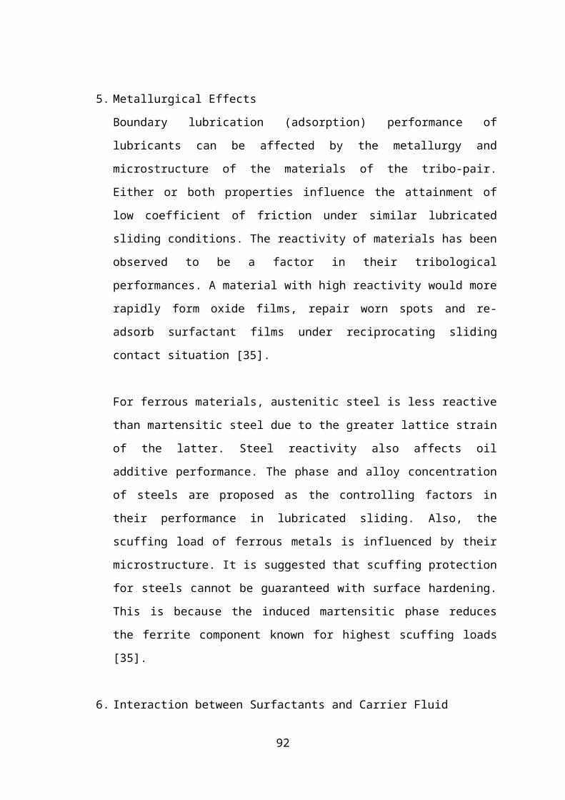
Figure 4-20: Lubrication mechanisms of SiO2 NPs in oil [112]
The lubrication mechanisms of silica NPs is schematically presented in Figure 4-5, adopted
from Sui [112]. In another study, a real-time field test on the cylinder liner of a locomotive
engine [129] a silicate powder additives of sizes 1 µm by 20-40 nm was added to a lubricant.
The silicate contains Al, Si, and O. After running the engine for 260,000 km under
lubrication with the oil-silicate mixture, it was observed that the silicate particles repaired the
pits and cracks on the worn surfaces.
4.5.3 Graphite Nanoparticle Additives
Graphite (Carbon, C) is a traditional solid lubricant. Its nanomaterial derivatives are potential
green additives in both oil and grease lubricants. Graphite, graphite oxide, graphene oxide
and graphene have similar basic chemistry. The disk-on-disk tribo-tests on graphite
nanolubricants proposed that graphite NPs act as ball-bearings within the sliding contact. The
0.5 vol. % mixture has optimal performance indicators such as: lowest friction coefficient
range on the Stribeck curve, lowest rise in temperature with increasing load and lowest AFM
3D surface roughness, Ra [118].
Graphite NPs as additives in vegetable based oil have been tested in a pin-on-disk tribometer
at RT. The graphite NPs used have two different particle sizes: 35 nm and 80 nm. The
vegetable oil and its mixtures with the NPs were tested at RT only. The COF results show the
highest friction reduction for the 0.25 vol. % oil-nano-graphite mix of the 35 nm particle size,
92
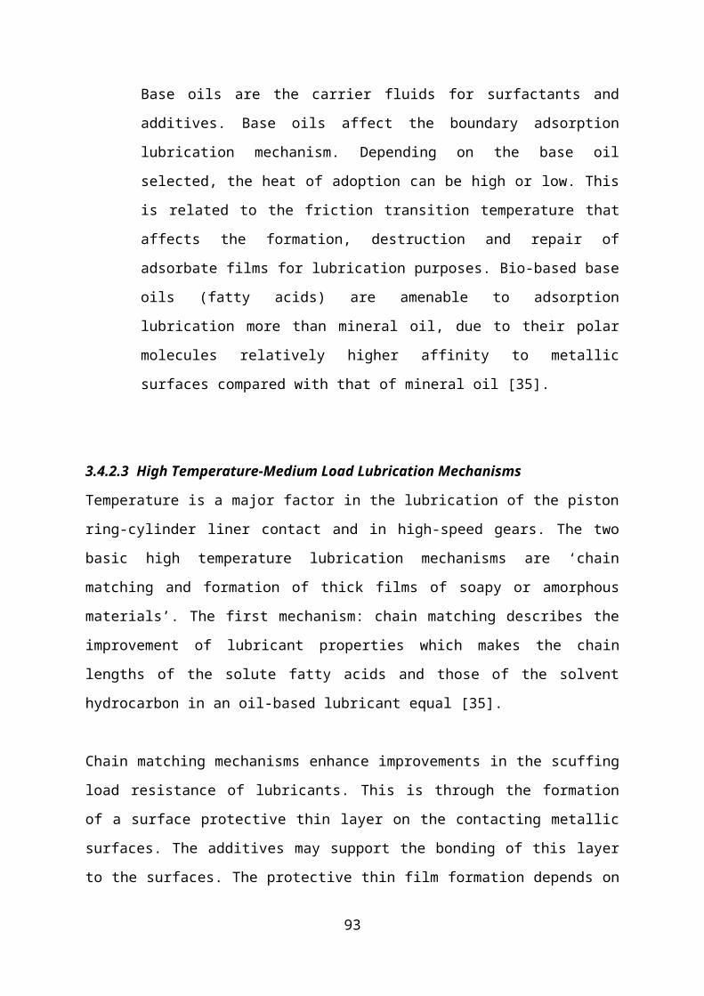
compared to the pure oil and the 0.25 vol. % mixtures with the 80 nm size graphite NPs.
Also, the wear loss is lowest for the 35 nm sized nano-graphite at 0.25 vol. %. The FE-SEM
and EDS images and chemical analyses show the presence of graphite (C) on the wear track.
These explain formation of the tribofilms responsible for lowering friction coefficient,
frictional heat and wear in the sliding contact [130].
4.5.4 Composites of Any Two of Alumina, Silica and Graphite Nanoparticles
Nanoparticles of the alumina/silica composite have been investigated by four-ball and thrust-
ring tests. The composite has a particle size of about 70 nm. The oil-nanomaterial mixes of
0.05, 0.1, 0.5 and 1 wt. % were tested at 75oC. The 0.5 wt. % mixture performed optimally
with 50% reduction in friction coefficient; better than those of alumina (22%) and silica
(25%) respectively. The near-spherical shapes of the NPs make them act as nano-bearings
within the contact. The nano-bearings change sliding to rolling friction. Lower NPs
concentrations reduce the available quantity of nano-bearing particles in the sliding contact,
leading to increased friction and wear. As well, above the optimal concentration, friction and
wear is aggravated [100].
The pin-on-disc tribotesting of composite powders of silica and graphene oxide as additives
in ethylene glycol at only 0.125 wt. % showed 38 % reduction in COF and 31 % reduction in
disc wear. An optimal silica/graphene oxide composition ratio of 90/10 on weight basis is
suggested. With modifications, the spherical shape of the silica NPs (540 nm) and high
specific area of composites enhanced their dispersion in the lubricant. This equally enhances
the integration of their lamellar in tribofilm formation and the usual NP bearing i.e. slide-to-
roll mechanisms [131]. The spherical shape of the silica/graphene oxide NPs enhances their
lubrication effectiveness like the case with silica NPs [126]. At the low speed and high load
known for boundary lubrication, the silica-graphene oxide NPs reduce the friction coefficient
of the base oil in the steel-steel tribo-contact. The COF over time reduces from the range
0.16-0.18 to around 0.10-0.11 in the sliding contact [131].
93
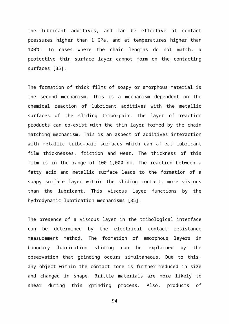
4.6 The Polyvit Nanoparticle Additive
Polyvit is a hybrid NPs system of three materials namely alumina, silica and plasma-treated
graphite. As explained by its manufacturer [145], the polymer silica (SiO2) in the Polyvit
mixture is in amorphous form. The NPs’ mean size is in the range of 7-15 nm. One of its
lubrication mechanisms is to build an elastic 3-dimensional ball-shaped net structure on the
wear track or friction zone. The ball-shaped nanoscale SiO2 structures as shown in Figure 4-6,
interconnect with lubricant molecules to form a net or tribofilm on the wear track.
The Polyvit NPs are observed to agglomerate in lubricant. It interacts with the lubricant. The
oil molecules fix into the inner surface of the polymer SiO2 units and form silica gel. During
the operation of the tribo-pair, the silica gel would sediment on the wear track. The frictional
energy allows the building up of oil-bearing chains of molecules.
Figure 4-21: The nanoscale ball-shaped structure of SiO2
It is this chains or net that turn sliding friction into a lower rolling friction. This is proposed
as the mechanism by which the Polyvit NPs separate tribo-pair sliding surfaces from direct
contact [145]. Thus, the Polyvit NPs can perform as a boundary lubrication additive, where
friction and wear are reduced by adsorbed tribofilms on the contacting surfaces [35]. The
micrograph of the Polyvit NPs as presented by Efficiency Technologies [145] is shown in
Figure 4-7.
94
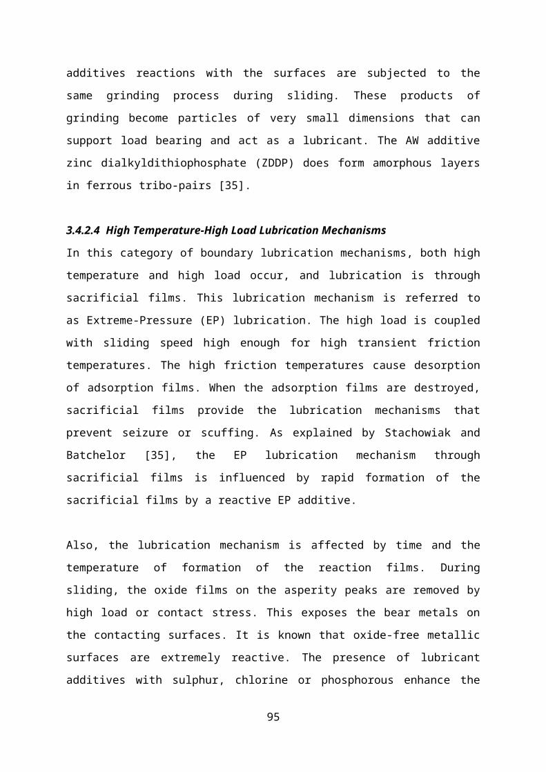
Figure 4-22: The micrograph of Polyvit NPs (from Efficiency Technologies [145])
The Polyvit has been observed to reduce friction and wear when mixed with mineral oil-
based lubricants at very low concentrations, less than 0.1 wt. %. It can behave in a similar
manner as other NPs in lubricated contacts, but its behaviour under boundary lubrication
conditions is yet unclear. Polyvit has a good miscibility with conventional lubricants and
additives. It also has some good residual effects on the tribological contacting surfaces after
lubricant change [145]. This is the first study of Polyvit NPs as additives in a biolubricant.
Also, the behaviour of the NPs in a biolubricant under boundary lubrication conditions would
be investigated.
4.7 Conclusions
The properties of NPs relevant to tribology and lubrication mechanisms of NPs have been
explained with some examples from literature. The size, shape and chemistry of the NPs
supplied to a contact through the lubricant are essential to tribological performance. Also, the
roughness of the surface, contact pressure and temperature are factors which influence the
occurring lubrication mechanisms. Four lubrication mechanisms were described such as
rolling effect, mending mechanism, protective film and polishing effect respectively.
95
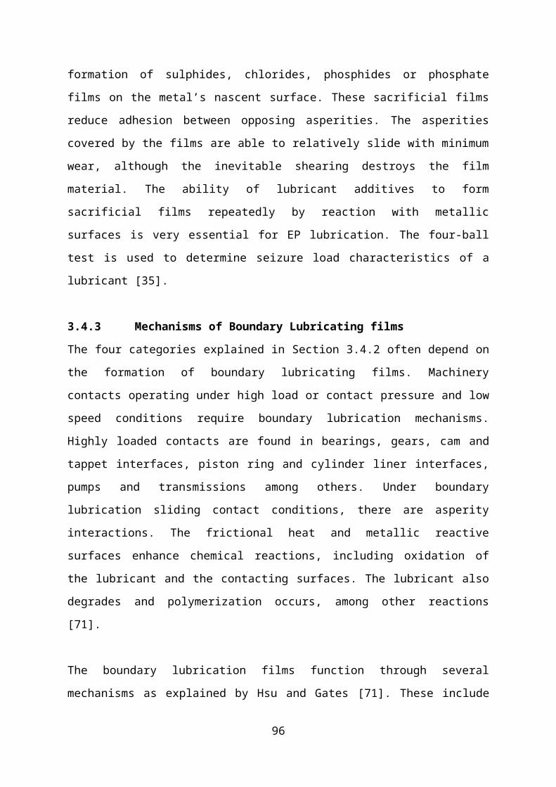
The NPs addition to mineral oil, paraffinic oil, poly alpha olefin and rapeseed oil
(biolubricant) were reviewed, leading to understanding of the mechanisms of lubrication by
NPs additives. The optimal concentration of the NPs in lubricant is usually low, between 0.05
to 2 wt. %. NPs were observed to behave as AW additives in boundary lubrication sliding
conditions. They reduce the coefficient of friction in some cases and behave otherwise in
some cases. So also is the co-existence of various forms of wear on the contacting surfaces.
The common boundary lubrication mechanism with the NPs additives has been tribofilm
formation. This is usually evidenced by presence of the constituent elements of a NP on the
wear surface.
The Polyvit NPs additive was introduced as a hybrid of alumina, silica and graphite. Some
applications of alumina, silica and graphite NPs separately and in combinatorial form are
reviewed. Although, low concentrations of NPs are proposed to be good enough for
lubricating tribofilm formation, yet there is an optimal concentration for each NPs additive.
In many applications of the NPs of silica, for example, the optimal concentration is 0.1 wt. %.
The lubrication mechanism of the Polyvit NPs was explained as being through formation of
tribofilms of silica on the contacting surfaces. This gives an idea of things to expect in the
tribotests for characterisation of the lubricant-NPs mixture. The next chapter presents the
HFRR tribotest in boundary lubrication conditions under a load of 40 N.
96
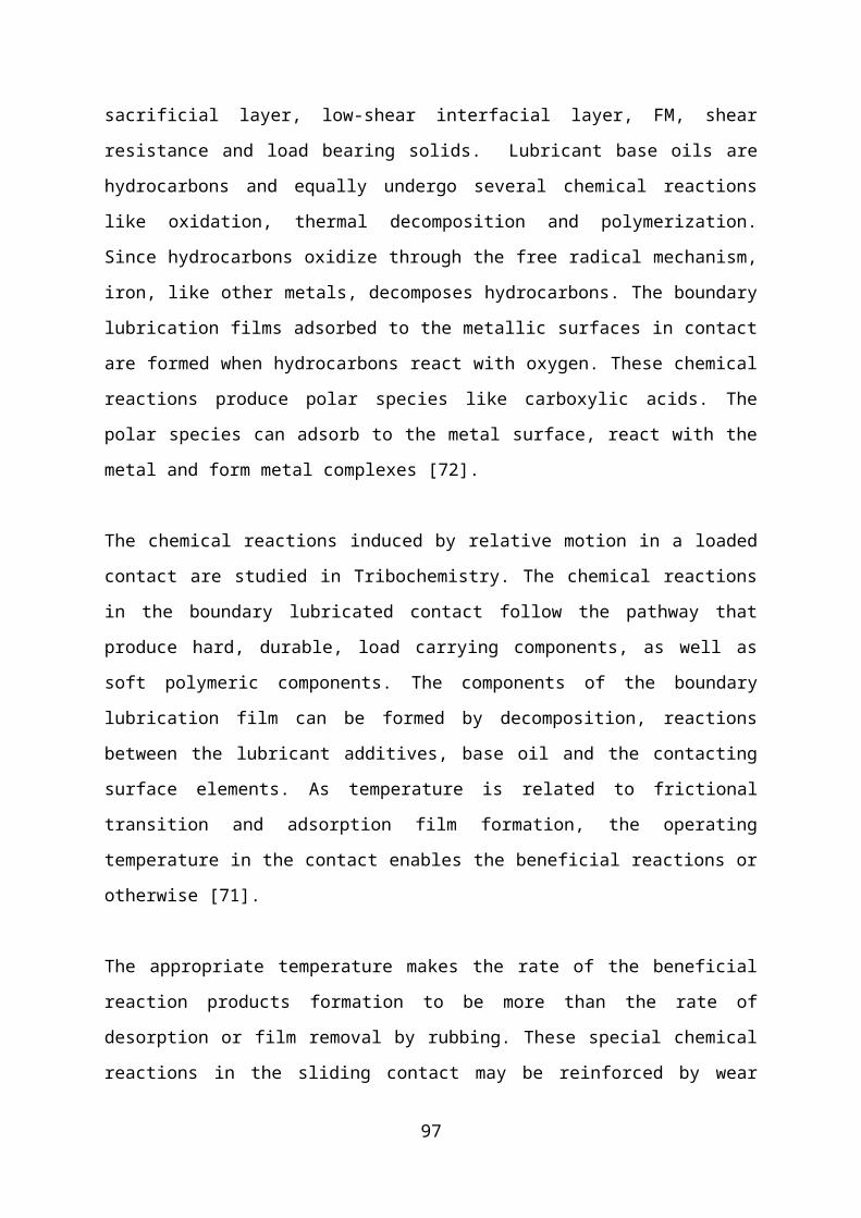
5 Ball-on-flat Test of the Lubricants and NPs under Load, 40 N
This chapter consists of the first series of tribotesting. The materials and test conditions are
presented, along with calculations of the Hertzian contact pressure and the Lambda
parameter. The use of some analytical tools in the study is briefly described. The WSW and
coefficient of friction data are used to explain the tribological behaviours of the Polyvit NPs
additives in a lubricant. The hardness of the flat sample effects on its friction and wear
behaviours is explained as a result of the high normal load of 40 N. The wear mechanisms on
the flat and ball samples are analysed with SEM/EDX showing that tribofilms are difficult to
form on the wear surface at such a high load.
5.1 The Ball-on-flat Reciprocating Sliding (HFRR) Tribotest
The high frequency reciprocating rig (HFRR) is good for comparative tests that are controlled
and can have a variety of lubrication regimes in their motion. The reciprocating motion of the
piston ring-cylinder liner can be simulated with the HFRR as proposed by ASTM [132]. The
lubricant and NPs mixtures, temperature and their influences on the evolution of friction and
wear mechanisms are major parameters of interest. The Plint TE 77/8287 (Phoenix Tribology
Ltd) high frequency reciprocating rig (HFRR), shown in Figure 5-1, was utilized for this
investigation.
A schematic of the ball-on-flat (plate) contact is shown in Figure 5-2. The HFRR creates a bi-
directional sliding motion between samples, while a loading mechanism applies a selected
load on the test samples. The flat sample, screwed to base of the oil bath, is immersed in oil
during tests. The upper sample is a spherical ball, with a linearly reciprocating motion.
Frictional force is recorded through a load cell. The friction force data is acquired with the
use of the NI LabVIEW Data Acquisition (DAQ) system. A variable speed motor generates
the reciprocating of the ball sample holder arm movement using the scotch yoke mechanism.
During the test, a computer (PC) displays the like friction force over the duration of the
experiment.
97
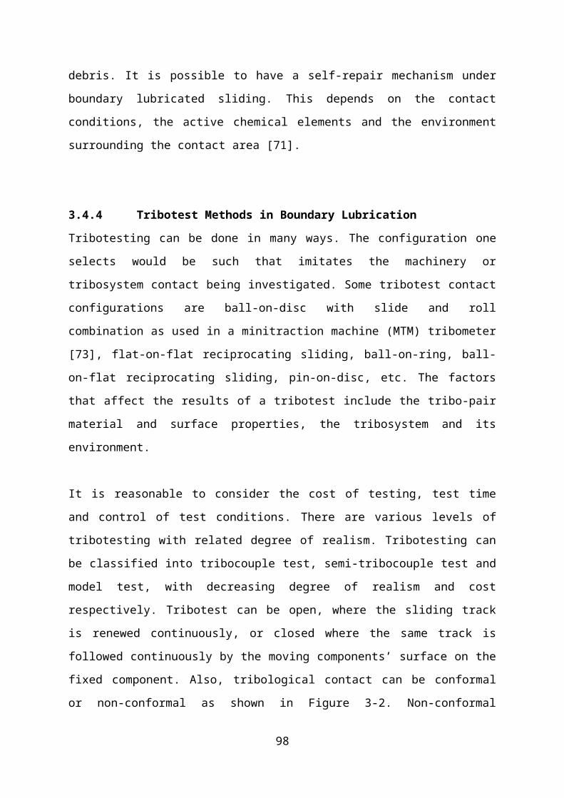
Figure 5-23: Annotated image of the Phoenix Plint TE 77 HFRR tribometer
Figure 5-24: Schematic of the ball-on-flat contact
5.2 Materials
The materials used for this investigation are the ball and flat samples for the tribological ball-
on-flat non-conformal contact. Also the lubricants are a biolubricant – rapeseed oil and a
typical mineral oil-based engine lubricant. These materials are briefly described.
5.2.1 The ball and flat samples
The ball test samples are made from chrome steel material, AISI52100. It has relatively
higher hardness compared to cast iron. The hardness range of between 700 and 900 Hv is
98
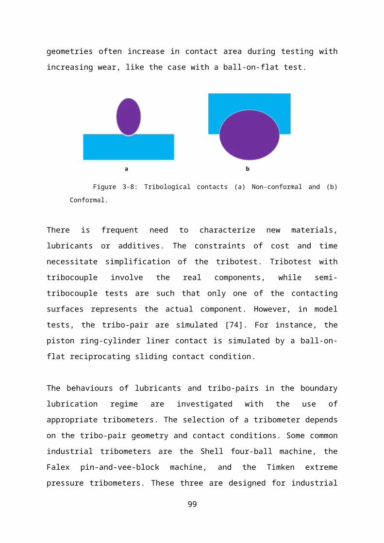
common for AISI52100, while for the EN-GJL-250 grey cast iron (GCI) it ranges between
224 and 271 Hv. The material and manufacturing (or procurement) specifications of the test
samples are shown in Table 5-1. As-supplied chrome ball from Phoenix Tribology Ltd, as
shown in Figure 5-3 (a); within a rigid holder.
The holder is designed to fit into the upper reciprocating arm of the HFRR. The ball has a
diameter of 6 mm and a mirror-finish surface. No further surface finish was done on it before
tests. Figure 5-3 (b) shows the flat sample machined from EN-GJL-250 material. The EN-
GJL-250 is one of the most widely used ferrous materials for manufacture of automotive
engine cylinder liners.
Figure 5-25: Pictorial view of (a) ball with rigid holder and (b) flat friction coupon. All dimensions in mm.
Table 5-3: Material properties of the ball and flat samples
Property Ball Sample Flat SampleName AISI 52100 EN-GJL-250Manufacture As-supplied Machined, Ground and PolishedSurface roughness Mirror-finish 0.09 ≤ Ra≤ 0.30 μmTest position and motion Upper and reciprocating Lower and stationaryDimensions, mm Radius, 3 L x B x H = 66 x 25 x 4Young’s modulus, GPa 210 92.3Hardness (range), Hv 700-900 224-271 Tensile strength, MPa 2240 250Poisson’s ratio 0.3 0.211
This is understandably due to its lower cost compared to other Fe-based automotive materials
and an array of desired operational advantages. These qualities include [133]: thermal
conductivity, vibration damping, wear resistance and mechanical property. The machined flat
99
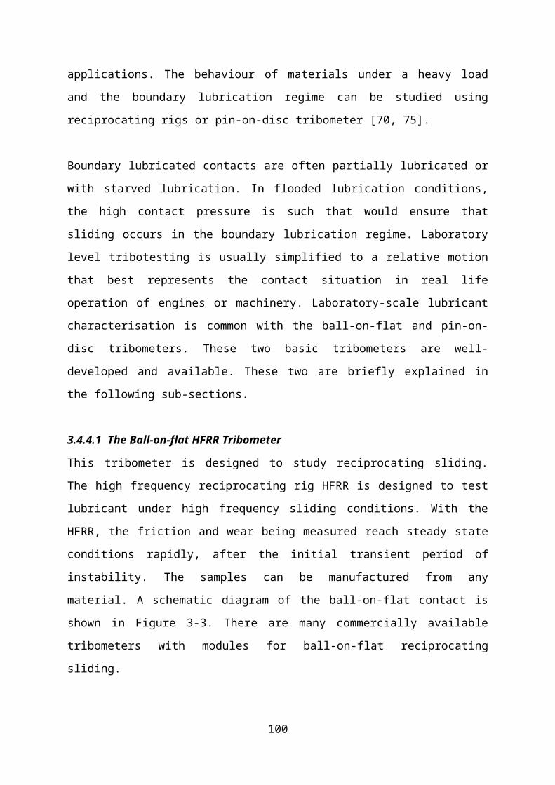
samples were ground and polished to an average surface roughness, Ra less than 0.30μm.
Grinding and polishing reduce machining effects on the surface such as flaws, l6ay and
texture.
5.2.2 The Lubricants: Rapeseed Oil and Mineral Oil
The lubricants used are rapeseed oil as a biolubricant and mineral oil. The rapeseed oil is
selected due to its availability in the UK. Also, the plain biolubricant is tested without any
other additive to show the lubricating mechanisms of the NPs.
Typical mid-market fully formulated engine oil is selected as control for this investigation. Its
properties as presented by the manufacturer are shown in Table 5-2. Rapeseed oil is
commercially abundant and has been proposed as alternative base oil for automotive
crankcase lubricant [85]. Typical lubrication properties of unmodified rapeseed oil as
presented by [134] and [135] are as shown in Table 5-3. The extra virgin cold pressed
rapeseed oil was selected and procured for this investigation.
Table 5-4: Properties of mineral oil
Properties Method Shell Helix HX5Viscosity Grade 15W-40Kinematic Viscosity @ 40oC, cSt IP 71 105.4Kinematic Viscosity @ 100oC, cSt IP71 13.9Viscosity Index IP 226 132Density @ 15oC, g/cm3 IP 365 0.885Flash Point (PMCC), oC IP 34 220Pour Point, oC IP 15 -30
Table 5-5: Properties of rapeseed oil
Properties Standard Rapeseed oilViscosity @ 100 oC (cSt) ASTM D445 7.9 [135]Viscosity @ 40 oC (cSt) ASTM D445 35.1 [135]Pour point (oC) ASTM D97 -19.1Flash point (oC) ASTM D92 320Viscosity index ASTM D2270 207 [135] Specific gravity @ 15oC ASTM D287 0.85Oxirane content (%) AOCS cd 9-57 0Biodegradability (%) CEC-L-33-A93 >95Rotary bomb oxidation time (min) ASTM D2272 16Iodine value AOCS cd 1-25 120
100
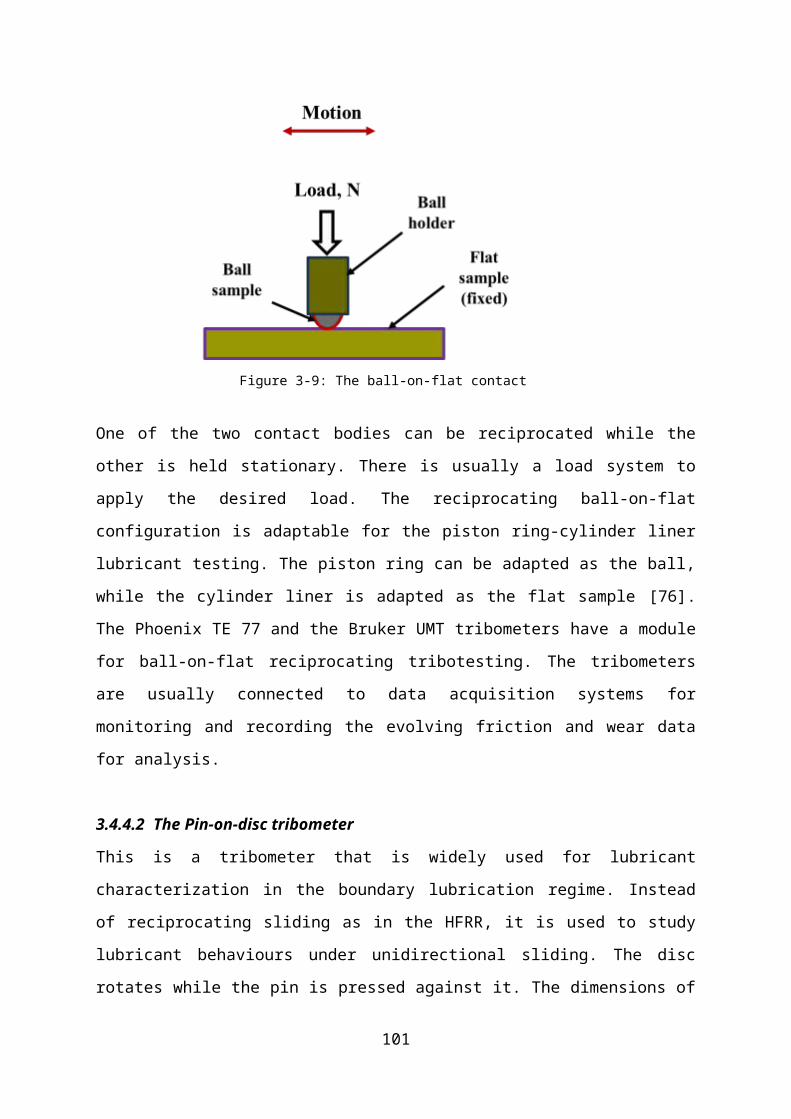
5.2.3 The Polyvit Nanoparticles
The Polyvit (Alumina-silica-graphite hybrid) NPs were supplied by Efficiency Technologies,
U.K. It has a whitish appearance and is powdery in form. The properties of the NPs as
presented by the manufacturer are as shown in the Table 5-4. The Polyvit NPs additives were
added to both lubricants in the same concentration of 0.1 wt. %. As the study is to understand
the behaviour of the Polyvit NPs in oil, surfactants and other lubricant additives were not
added to the NPs in the biolubricant. Although the fully formulated lubricant used as control
contains the whole range of conventional additives, yet the effects of the NPs would still be
apparent.
Table 5-6: Properties of the Polyvit NPs
AppearanceName (Source) Polyvit powder (Efficiency Technologies, U.K.)Quantity (supplied) 1.26 gForm Amorphous (powder)Colour WhiteSmell Odourless Physical and chemical propertiesSize 9 nm pH at 20oC 3.6-4.5 (40 g/l) (Suspension in 10W40 oil)Melting point About 1700oCDensity at 20oC Approximately 2.2 g/cm3 Tapped Density About 50 g/lMethod DIN/ISO 787/11
5.3 The Ball-on-flat Test Conditions
The ball samples were used for tests as received. The general conditions for the linearly
reciprocating ball-on-flat sliding wear tests are stated in Table 5-7. The flat sample material is
softer than chrome steel (ball sample). In agreement with the Archard wear law, it is assumed
that the wear of the harder ball sample is insignificant compared to that of the softer flat
sample. Using the optical microscope and weight change analysis after experimental tests, no
significant changes were observed on the ball sample. The load of 40 N was selected as
sufficient to give a significant wear scar on the flat sample. This was determined after
101
experimental tests. The equations used for the calculation of the maximum contact pressure
(3.98 GPa) are shown in section 5.3.1
5.3.1 Contact Pressure Calculation
The nominal contact pressure is the sum of the piston ring elastic pressure and cylinder gas
pressure acting on the back side of the piston ring and pressing it against the walls of the
cylinder liner [76].The ball-on-flat contact can be used to represent the piston ring-cylinder
liner contact. This is similar to the contact between a sphere and a plane surface, shown in
Figure 5-4 as described by Stachowiak [56]. The radii of curvature of a plane surface are
infinite and symmetry applies to the two bodies in contact.
Figure 5-26: Ball-on-flat contact
The contact parameters and relationships are stated below:
I. The reduced radius of curvature, R ’ in meters:
1R '=
1Rball
+ 1∞
+ 1Rball
+ 1∞
= 2Rball
Equation 5-16
Where:
Rball is the radius of ball in the ball-on-flat contact, in meters (m).
The ball radius is 6 mm or 6E-3 m
II. The reduced Young’s modulus, E ’
1E'=
12(1−v A
2
EA+
1−vB2
EB)
Equation 5-17Where:
102
vA and vB are the Poisson’s ratios of the contacting bodies ‘A’ and ‘B’ respectively;
EA and EB are the Young’s moduli of the contacting bodies ‘A’ and ‘B’ respectively (Pa).
The Poisson’s ratio for steel, vsteel is 0.3 and its Young’s modulus, E steel is 2.1 x 10¹¹ Pa.
The Poisson’s ratio [89] for grey cast iron (GCI), vGCI is 0.211 and its Young’s modulus,
E I GCI is 92.30 GPa.
III. The radius of the contact area, a, is given by:
a=¿ Equation 5-18
Where:
a is the radius of the contact area, m;
W is the normal load, N;
R ’ is the reduced radius of curvature, m;
E ’ is the reduced Young’s modulus, Pa.
IV. The maximum, Pmax and average, Paverage contact pressures, in MPa, are expressed as follows:
Pmax=3W
2π a2
Equation 5-19
Paverage=W
π a2
Equation 5-20
V. The maximum deflection, δ, is given by the expression:
δ=1.0397 ¿Equation 5-21
VI. Maximum shear stress
τ max=13
Pmax
Equation 5-22
103
VII. Depth at which maximum shear stress occurs
z=0.638 aEquation 5-23
The material properties and parameters used in contact pressure calculations are as presented
in the Table 5-5.
Using the parameters in Table 5-5, and a normal load of 40 N, the initial maximum contact
pressure is calculated as 3.98 x 10⁹ N/mm2 or 3.98 GPa. The contact area is 6.930 x 10⁻⁵ m2.
The MS Excel analysis is shown in Fig. 18. The selected load of 40 N is highlighted with the
resulting maximum contact pressure. However, the requisite EHL film thickness and Lambda
ratio analyses are presented in Section 5.3.2.2.
Table 5-7: Material properties of the ball and flat tribo-pair.
S/N
Property / Parameter Value Dimension
1 Young’s modulus for steel (ball) 2.1 x 10¹¹ Pa2 Poisson’s ratio of steel 0.33 Young’s modulus for GCI (flat) 9.23 x 10¹⁰ Pa4 Poisson’s ratio of GCI 0.2115 Radius of chrome steel ball 3 x 10⁻³ m
104
1 2 3 4 5 6 7 8 9 9a 10 11 12 13 14 16 17 18
Ball
radi
us
Flat
radi
us
Cont
act L
oad
Poiss
on's
Ratio
, Bal
l.
Poiss
on's
Ratio
, Fla
t.
Youn
g's M
odul
us, B
all.
Youn
g's M
odul
us, F
lat.
Redu
ced
Radi
us
1/E'
Redu
ced
Youn
g's M
odul
us
Cont
act a
rea
Max
imum
con
tact
pre
ssur
e
Aver
age
cont
act p
ress
ure
Max
imum
Defl
ectio
n
Max
imum
She
ar S
tres
s
Dept
h at
whi
ch M
axim
um S
hear
Str
ess o
ccur
s
Symbol R1 R2 W v 1 v 2 E1 E2 R' E' R'/E* a Po p avg δ τ zUnits m m N N/m2 N/m2 m N/m2 m2 N/m2 N/m2 m Pa m
Test 1 3.00E-03 5 0.3 0.211 2.05E+11 9.23E+10 1.50E-03 7.40E-12 1.35E+11 1.11E-14 3.46494E-05 1.99E+09 1.3E+09 1.01E-06 6.63E+08 2.21063E-050
Test 2 3.00E-03 30 0.3 0.211 2.05E+11 9.23E+10 1.50E-03 7.40E-12 1.35E+11 1.11E-14 6.29622E-05 3.61E+09 2.4E+09 3.33E-06 1.20E+09 4.01699E-051 3.00E-03 10 0.3 0.211 2.05E+11 9.23E+10 1.50E-03 7.40E-12 1.35E+11 1.11E-14 4.36555E-05 2.51E+09 1.7E+09 1.6E-06 8.35E+08 2.78522E-052 3.00E-03 20 0.3 0.211 2.05E+11 9.23E+10 1.50E-03 7.40E-12 1.35E+11 1.11E-14 5.50025E-05 3.16E+09 2.1E+09 2.54E-06 1.05E+09 3.50916E-053 3.00E-03 30 0.3 0.211 2.05E+11 9.23E+10 1.50E-03 7.40E-12 1.35E+11 1.11E-14 6.29622E-05 3.61E+09 2.4E+09 3.33E-06 1.20E+09 4.01699E-054 3.00E-03 40 0.3 0.211 2.05E+11 9.23E+10 1.50E-03 7.40E-12 1.35E+11 1.11E-14 6.92988E-05 3.98E+09 2.7E+09 4.03E-06 1.33E+09 4.42126E-055 3.00E-03 50 0.3 0.211 2.05E+11 9.23E+10 1.50E-03 7.40E-12 1.35E+11 1.11E-14 7.46499E-05 4.28E+09 2.9E+09 4.68E-06 1.43E+09 4.76266E-056 3.00E-03 60 0.3 0.211 2.05E+11 9.23E+10 1.50E-03 7.40E-12 1.35E+11 1.11E-14 7.93273E-05 4.55E+09 3E+09 5.28E-06 1.52E+09 5.06108E-057 3.00E-03 70 0.3 0.211 2.05E+11 9.23E+10 1.50E-03 7.40E-12 1.35E+11 1.11E-14 8.351E-05 4.79E+09 3.2E+09 5.86E-06 1.60E+09 5.32794E-05
Calculation of Contact Parameters: Ball-on-Flat TriboTests
Figure 5-27: Calculation of maximum contact pressure for the ball-on-flat contact. Highlighted is the selected
load of 40 N and maximum contact pressure of 3.98 GPa.
5.3.2 Minimum Film Thickness and Lambda Ratio Analysis
In order to be sure that the tests at least start running in the boundary lubrication condition,
the lambda ratio was calculated as shown in this section. The calculated Lambda values show
that the test runs in the boundary lubrication regime. It is usually observed that lubricated
tribotest begins under the calculated contact pressure, referred to as the initial or maximum
contact pressure. In the HFRR, the normal load corresponding to the desired contact pressure
would be used.
The contact of piston rings and cylinder liner is conformal, as the piston ring forms an
annular inner ring inside the cylinder liner. The ball-on-flat configuration is non-conformal.
The ball-on-flat however represents the point contact between the elemental section of the
piston ring and the cylinder liner surface. The reciprocating motion of the piston in the
cylinder also is fairly well simulated by the HFRR. It is essential to know that the test runs in
boundary lubrication regime. This is evidenced by the minimum film thickness and Lambda
value calculations within the appropriate operational ranges.
5.3.2.1 Minimum film thickness
The calculation of the EHL minimum film thickness is based on Equation 5-9 [136]:
105
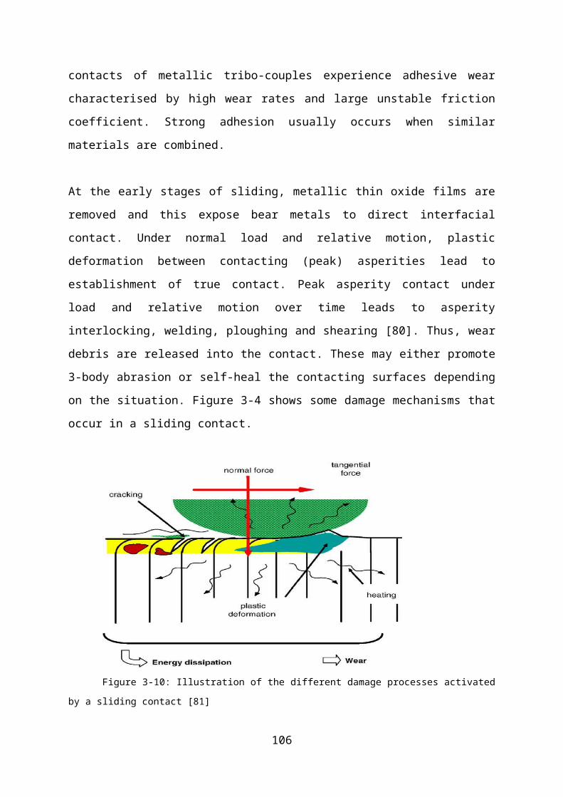
h0
R ' = 3.63 ¿
Equation 5-24
Where:
h0 is the minimum film thickness, m;
U is the entrainment surface velocity, m/s, i.e. U =(U A+U B)
2
Where the subscripts ‘A’ and ‘B’ refer to the velocities of bodies ‘A’ and ‘B’
respectively;
η0 is the viscosity at atmospheric pressure of the lubricant, Pas;
E' is the reduced Young’s modulus, Pa;
R' is the reduced radius of curvature in the direction of rolling, i.e.
R'= 1(Rax+Rbx )
meters, m;
α is the pressure-viscosity coefficient, m2/N;
W is the contact load, N;
k is the ellipticity parameter defined as: k=ab , where ‘a’ is the semi-axis of the
contact ellipse in the transverse direction, and ‘b’ is the semi-axis in the
direction of motion. Both ‘a’ and ‘b’ are in meters, m.
For point contact, k=1.
The Equation 5-9 is applicable for k values from 0.1 upwards. This equation can be used for
many material combinations including steel-steel tribo-pair, up to maximum pressures of 3 –
4 GPa. Using the contact configuration of ball-on-flat and the contact parameters, at a load of
40 N, the calculated initial maximum contact pressure is 3.98 GPa.
The pressure-viscosity relationship, α , is a function of the molecular structure of the lubricant
and its physical characteristics such as molecular interlocking, molecular packing and
rigidity, and viscosity-temperature characteristics. It can be calculated using the equation:
α=( 0.6+0.965 log10 η10) x 10−8
Equation 5-25
106
Where:
α is the pressure-viscosity coefficient, m2/N or Pa-1.
η0 is the lubricant viscosity under atmospheric pressure, cP,
The kinematic viscosity of lubricants can be converted to absolute or dynamic viscosity by
using the Equation 5-11:
Dynamic viscosity ,Pas=Kinematic viscosity , cSt x Density ,g /¿cm3x10-3
Equation 5-26
However, the pressure-viscosity of a lubricant decreases with increasing temperature. This
can be estimated by using different methods explained by Biresaw and Bantchev [137].
5.3.2.2 The Lambda Ratio Analysis
Using the EHL film thickness analysis, the minimum film thickness at 40oC were calculated
based on Equation 5-9. The estimates of the pressure-viscosity coefficients for mineral oil
and rapeseed oil were adopted from literature. The Lambda parameter for each of the
lubricants is calculated based on the Equation 5-12:
λ=h0
√ (RqA2 +RqB
2 )
Equation 5-27
The Lambda values are significantly less than 1. These show that the tests begin to run in the
boundary lubrication regime. Table 5-6 shows the typical values of minimum film thickness
and lambda values at 40oC for the selected lubricants. The viscosity of the lubricant is known
to reduce with increasing temperature under constant pressure. Therefore, both the minimum
film thickness and Lambda parameters would decrease with temperature increase and become
lower than they are at 40oC. Thus, since the tests run in boundary regime at 40oC, they would
run further in the boundary lubrication regime at higher temperatures.
107
Table 5-8: Calculated minimum film thickness and Lambda values under Load, 40 N at 40oC.
Lubricant Minimum film thickness, nm Lambda, λMineral oil 8.298 0.0184Rapeseed oil 3.083 0.0068
Parameter values in Table 5-6 are based on the maximum Ra of 0.3 and 0.2 µm for flat and
ball samples respectively. The pressure-viscosity coefficient at 40oC for mineral oil [138] is
14.4934 GPa−1 and that for rapeseed oil [137] is 9.35 GPa−1. The calculation of the values of
the minimum film thickness and lambda ratio is shown in Figure 5-6. The tribotest runs in the
boundary lubrication regime. Thus, boundary lubrication properties of the lubricant are the
major friction and wear mitigation possibilities.
Minimum Film Thickness and Lambda Ratio Analysis
Lubricant Temperature, T 40 °CLoad, w 40 NBall Radius 3 mmSliding speed 0.13 m/sModulus of elasticity of Ball Specimen 210 GpaModulus of elasticity of Flat Specimen 92.3 GPaPoisson ration of Ball Specimen 0.3 Ra Rq
Poisson ration of Flat Specimen 0.211 Flat 0.3 0.375 mmEffective Radius in x direction, Rx 0.0015 m Ball 0.2 0.25 mmMean surface velocity, u 0.065 m/sEffective Modulus of Elasticity, E' 1.3619E+11 Pa RMS roughness 0.450693909Dimensionless Load Parameter, W 0.00013054 Rq = 1.25 RaElipticity Parameter, k 1.0339 Since, Rx = Ryr.m.s roughness, s* 1.2502E-06 m
Lubricant
Kinematic Viscosity at 40°C (cSt)
Density at 15°C (g/cm3)
Density at 40°C (g/cm3)
Dynamic viscosity at 40 C (Pa.s)
Pressure Viscosity-coefficient (Pa-1)
Dimensionless Material Parameter, G
Dimensionless Speed Parameter, U
Dimensionless Minimum Film Thickness, Hmin
Minimum Film Thickness, hmin (m) Lambda Ratio
Mineral Oil 105.4 0.885 0.8714 0.091845115 1.44934E-08 1973.880001 2.92233E-11 5.53215E-06 8.2982E-09 0.0184121Rapeseed oil 35.1 0.85 0.83693 0.029376376 9.35E-09 1273.389294 9.34697E-12 2.05579E-06 3.0837E-09 0.00684208
𝒉𝟎𝑹′ = 𝟑.𝟔𝟑( 𝑼𝜼𝟎𝑬′ 𝑹′)𝟎.𝟔𝟖 (𝜶𝑬′)𝟎.𝟒𝟗 ( 𝑾𝑬′𝑹′𝟐)−𝟎.𝟎𝟕𝟑 (𝟏 − 𝒆−𝟎.𝟔𝟖𝒌)
8.29822E-09
3.08368E-09
01E-092E-093E-094E-095E-096E-097E-098E-099E-09
Mineral Oil Rapeseed oil
Minimum Film Thickness, m0.018412103
0.006842076
0
0.005
0.01
0.015
0.02
Mineral Oil Rapeseed oil
Lambda Ratio
𝒉𝟎𝑹′ = 𝟑.𝟔𝟑( 𝑼𝜼𝟎𝑬′ 𝑹′)𝟎.𝟔𝟖 (𝜶𝑬′)𝟎.𝟒𝟗 ( 𝑾𝑬′𝑹′𝟐)−𝟎.𝟎𝟕𝟑 (𝟏 − 𝒆−𝟎.𝟔𝟖𝒌)
8.29822E-09
3.08368E-09
01E-092E-093E-094E-095E-096E-097E-098E-099E-09
Mineral Oil Rapeseed oil
Minimum Film Thickness, m0.018412103
0.006842076
0
0.005
0.01
0.015
0.02
Mineral Oil Rapeseed oil
Lambda Ratio
Figure 5-28: Minimum film thickness and Lambda ratio analyses
108
5.3.3 Test Conditions with Load of 40 N
The mean sliding speed is set at a relatively low value (0.13 m/s) to simulate the low speed
high load tribo-contact situation at the start of automobile engines. At this stage, the
lubricating oil availability at the sliding interface is rather low. The lubrication mechanisms
in the contact depend on very thin lubricant films or/and tribofilms formed by the lubricant
and its additives interaction with the contacting sliding surface materials. Thus, the lubricant
and additives’ ability to support the operational load is paramount in this situation.
The test duration of 60 minutes is selected as sufficient for the sliding wear situation to
stabilize, to possibly form a tribofilm and produce a significant wear scar for comparative
analysis. The stroke length of 15 mm is an acceptable representation of the piston ring
displacement in relation to the stationary cylinder liner. The values of test parameters are
shown in Table 5-7.
Table 5-9: Plint TE77 Ball-on-flat experimental condition
Test conditions Parameter ValueTest duration 60 minutesNormal load, W 40 NMaximum contact pressure 3.98 GPaStroke length 15 mmMotor speed 262 rpm (Set to100 on Plint TE77)Sliding speed 0.13 m/s Temperature of lubricant RT (about 20), & 100oC.Lubricants Rapeseed oil (RO) and mineral oil (MO)NPs concentration 0.1 wt. %Ball (upper test piece) Chrome steel AISI 52100. 700 – 900 HvFlat (lower test piece) GCI BS1452 Grade250. 224 – 271 Hv
5.3.4 Specimen code, Temperature, Lubricants and Test Program
Tests were conducted using the selected lubricants and lubricant-NPs mixtures respectively at
RT and 100oC. The NPs concentration in the lubricants is 0.1 wt. %, which is 180.6 mg in
170 g or 200 ml of rapeseed oil and 183 mg in 177 g or 200 ml of the engine lubricant (MO).
Table 5-8 shows the composition of the lubricants. The RT ranges from 18 to 22oC during the
tests. The test program, Table 5-9, shows the flat sample code, lubricant and test temperature
respectively.
109
Table 5-10: Lubricant composition for the tribotest
Lubricant CompositionRO Rapeseed oilRO+NPs Rapeseed oil + 0.1 wt. % NPs MO Mineral oil MO+NPs Mineral oil + 0.1 wt.% NPs
Table 5-11: Test program and flat sample code
Flat Sample Code Lubricant Temperature, oCA3 RO and NPs 100A4 MO and NPs 100A5 RO 100A6 MO 100A7 MO RTA8 MO and NPs RTA10 RO RTA11 RO and NPs RT
5.4 Analytical Tools
The transmission electron microscopy (TEM) observations of the Polyvit NPs were
performed on FEI Tecnai T20 (FEI, the Netherlands) with EDAX system, operating at 200
kV. NPs were deposited on copper coated grid for characterisation. A small amount of NP
powder was added to ethanol and dispersed ultrasonically for 3 minutes. A copper grid was
dipped through the NPs-ethanol mixture. The copper grid with NPs was allowed to dry in
ambient air and preserved for TEM analysis.
The scanning electron microscopy (SEM) observations of the wear scar were carried out on a
Philips XL30s FEG operating at 20 kV acceleration voltage and equipped with EDX.
The wear scar surfaces were characterized for morphology and elemental analysis. The
preservation of the tribofilm evidence is important. This is why the wear scar is gently rinsed
[16, 17] or ultrasounded for a short time in organic solvents [110]. Heptane and petroleum
ether are some of the solvents usually used to remove lubricating oil stains from the wear
surface before analysis. In this study, pure heptane was used for removal of lubricant from
the test samples. The ultrasound treatment in heptane was limited to 60 seconds, after the
tribotest.
110
The Zeiss Optical Microscope Axio Imager A1m was used to obtain the micrographs of the
wear scars. The flat sample surface roughness and WSW were measured with a stylus surface
profilometer with Surftest SV-602 software. The surfaces of the tribo-pair are analysed for
evidence of wear and surface damage in order to explain the wear mechanisms in the contact.
The Vicker’s hardness measurement machine was employed for the determination of the flat
sample hardness. The Contour GT Microscope was used for the 3D image and surface profile
of the wear scars on the flat samples and the discs.
5.4.1 Characterisation of the NPs
The TEM image in Figure 5-6 (a) shows the spherical shape and size of the NPs. Although
the NPs look closely packed together in the TEM image, this does not imply agglomeration in
a fluid. The strong agitation by ultrasound is considered good enough to disperse the NPs in a
lubricant [102]. The re-agitation shortly before tribotest ensures proper NPs’ dispersion in
lubricant. The chemical elemental analysis reveals some elements present in the NPs. The
elements in the chemical composition of the NPs: silicon (Si) and oxygen (O) are shown
Figure 5-6 (b) while other elements such as Al and C are not. The film of NPs was deposited
on copper grid; this is the reason for copper (Cu) on the EDX spectra.
Figure 5-29: The TEM image of the NPs (a) and its EDX elemental analysis (b).
111
5.5 Friction Behaviour of the Lubricants
The evolution of friction in the ball-on-flat tribo-tests gives a view of the impact of NPs on
the lubricants and the lubrication process. At room and elevated temperatures, NPs’ friction
reduction effects are more prominent with fully formulated mineral oil than with rapeseed oil.
The conventional lubricant additives seem to support the friction reduction effects of NPs. As
shown in Figure 5-7, at RT, mineral oil shows higher coefficient of friction (COF) than
rapeseed oil. This may be due to the lubricity of biobased oils [139]. NPs tend to lower COF
when mixed with both oils at RT. This friction reduction improves with time for mineral oil.
However, the mineral oil tends to maintain a stable COF over time.
The elevated temperature friction behaviour of the lubricants and NPs is shown in Figure 5-8.
At 100oC the mineral oil-NPs mixture shows lower COF compared to mineral oil, and this
tends to be stable over time. This may indicate possible synergic action of the NPs with
ZDDP and conventional FM and AW additives. Although rapeseed oil exhibits lower COF
compared with rapeseed oil-NPs mixture, both rapeseed oil and rapeseed oil-NPs mixture
would require ZDDP for friction reduction at room and elevated temperatures.
Figure 5-30: The evolution of friction for the tribo-contact and lubricants at RT
112
Figure 5-31: The evolution of friction for the tribo-contact and lubricants at 100oC
Figure 5-32: The mean COF values for the tribo-contact and lubricants
Legends
MO_RT Mineral oil at RT
MO + NPs_RT Mineral oil and NPs mixture at RT
RO_RT Rapeseed oil at RT
RO + NPs_RT Rapeseed oil and NPs mixture at RT
MO_100 Mineral oil at 100oC
MO + NPs_100 Mineral oil and NPs mixture at 100oC
113
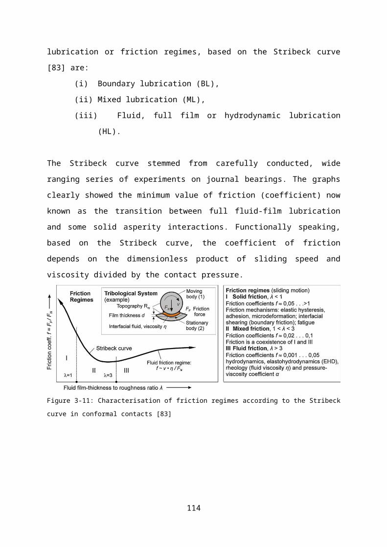
RO_100 Rapeseed oil at 100oC
RO + NPs_100 Rapeseed oil and NPs mixture at 100oC
The bar chart of Figure 5-9 shows the mean COF values for the sliding contact lubricated by
the lubricants. The error bars show the standard deviation, indicating the experimental spread
from the mean. The reduction in COF could be due to NPs lubricating mechanisms among
other boundary lubrication mechanisms. One of the NPs lubricating mechanisms is the nano-
bearing effects, which change sliding friction to rolling friction. This may be a reason for the
slight reduction in COF with NPs in mineral oil at both RT and 100oC.
As for rapeseed oil, the NPs seem to increase COF at elevated temperatures while they reduce
friction at RT. Based on the mean COF, the NPs lower friction in mineral oil at RT by 9.5 %,
and at 100oC by 1.4 %. For rapeseed oil, NPs reduce friction by 4.5 % at RT and increase
friction by 4.4 % at 100oC in the sliding contact.
The AW additive – ZDDP is present in the mineral oil and not so in rapeseed oil. It seems
NPs could work in synergy with ZDDP. Such a synergy has been reported between ZDDP
and WS2 NPs [16]; and also between ZDDP and MoS2 NPs [17]. The low temperature,
friction reduction benefits of NPs could remain during elevated temperature operation. As
shown in Figure 5-7, with NPs in mineral oil at RT, the COF reduces after the initial rise and
continues to reduce as sliding progresses. In addition, for NPs in mineral oil at 100oC shown
in Figure 5-8, the reduction in COF is stable with time.
The evolution of friction in the ball-on-flat tribo-tests gives a view of the impact of NPs
additivities on lubricants and the lubrication mechanism.. At 0.1 wt.% concentration, based
on calculated mean COF shown in Figure 5-9, the NPs slightly lowered friction in mineral oil
at RT by about 2 % and at 100oC by about 1 %. For rapeseed oil, the NPs seem to increase
friction by about 5.5 % at RT and increase by 6.4% at 100oC. The mean COF is shown with
error bar which is the standard error of the mean. This gives a measure of the uncertainty of
the estimated mean.
Friction coefficients when above 0.1 are in the boundary lubrication (BL) regime, while those
below 0.1 indicates a transition between BL and mixed lubrication (ML) regimes. From the
Stribeck curve in Figure 3-5, the mixed lubrication regime is characterised by COF values
114
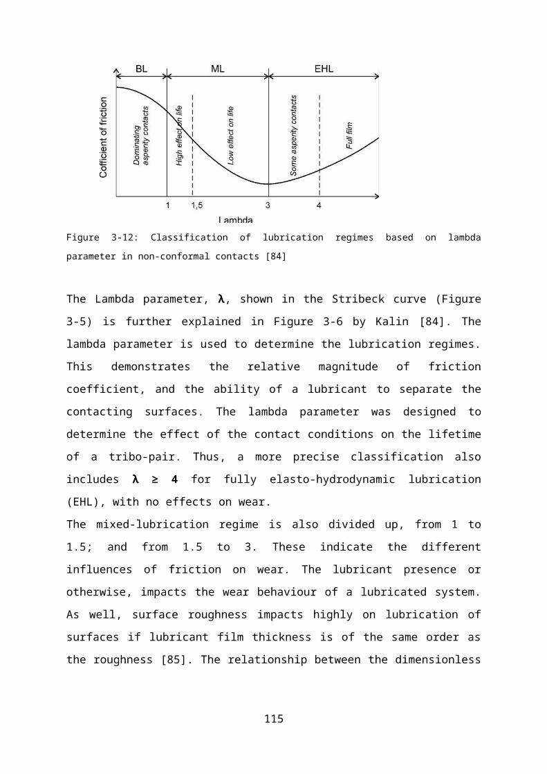
between 0.02 and 0.1, while BL shows COF ranging from 0.05 and 1. Thus, the tests can be
said to exhibit a mixture of boundary and mixed lubrication regimes.
One of the NPs’ lubricating mechanisms is the nano-bearing effect which changes sliding
friction to rolling friction. This may be a reason for the slight reduction in friction coefficients
with NPs in mineral oil. As for rapeseed oil, the NPs seem to increase friction coefficients at
both room and elevated temperatures. Many studies seem to focus on the action and
mechanisms of NPs to reduce friction coefficient in sliding contacts.
Although, the aim is to mitigate friction and wear issues in sliding situations where peak
asperities contact are possible, the lubrication regimes need to be clarified. Some studies as
well discussed NPs lubricating mechanisms in the elastohydrodynamic (EHL) regime. In this
study, the sliding contact operates under both boundary and mixed lubrication regimes. The
lambda calculation used the EHL formulae. The selections of load and contact pressure are
such as to give the lambda value for boundary lubrication regime. But the test results show
sliding under the two lubrication regimes, but looking more like BL.
5.6 Wear Behaviour of the Lubricants
The wear behaviour of the ball-on-flat tribo-couple was analysed based on the wear scar
width (WSW) on the flat sample. The mass loss and volume loss are used in gravimetric and
volumetric wear analyses respectively. The wear volume is usually based on the wear scar
length and width and depth, but there are some difficulties in accurate measurement of these
parameters. The mass loss in some cases is so low as to seem insignificant, especially with
mineral oil. So, to keep the error as low as possible, the WSW is adopted as a fair value to
indicate the extent of wear on the flat samples.
The average WSW, standard deviation and standard error are as shown in Table 5-10. These
were analysed and presented in the bar chart of Figure 5-10. The standard errors are shown as
error bars on the bar chart and show the uncertainty of the estimated mean WSW. The
variations of the hardness of the flat samples affect the wear behaviour. This is explained in
Section 5.7. The indentation (Vickers) hardness of the flat sample around the wear scar was
measured with a Vickers hardness machine. The WSW analysis was thereafter modified for
115
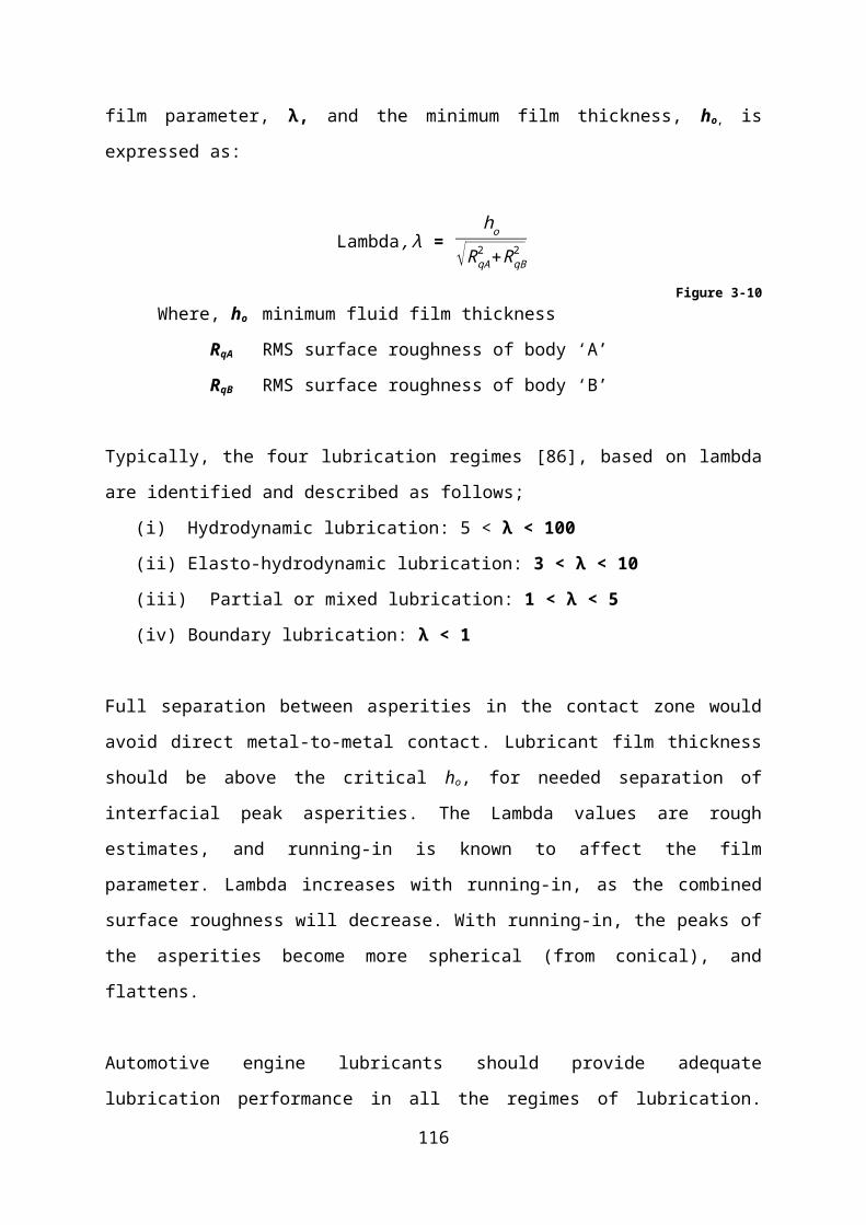
flat sample hardness within a limit of ± 20 HV. The WSW for test samples within this range
of material hardness is used to compare the lubricant behaviour in the tribo-contacts.
In general terms, mineral oil and mineral oil with NPs additives give lower WSW compared
to rapeseed oil and rapeseed oil with the NPs. This is true at both RT and 100 oC. NPs tend to
reduce wear at both temperatures, except when used in rapeseed oil at 100oC. Based on the
WSW shown in Figure 5-10, the Polyvit NPs reduce wear by about 12.5% when added to
mineral oil at 100oC.
Wear increased slightly when NPs were used in rapeseed oil at 100oC. Alves and co-workers
[140] observed similar wear behaviour with epoxidized soybean and sunflower oils mixed
with CuO and ZnO NPs. Ball-on-disk HFRR tests at 50oC showed poor AW ability for each
oil. They [140] proposed that this may be due to the influence of the chemical nature of the
biolubricants on film formation. At RT (Figure 5-10), the NPs reduce wear in mineral oil by
about 37.4% and in rapeseed oil, the NPs additives reduce wear by about 7.5%.
Table 5-12: Flat sample WSW (WSW)
S/N
Specimen Lube Mix T, oC Mean WSW, mm Std. Dev. Std. Error
1 A3_RO_NPs_100 RO + NPs 100 2.5060 0.2272 0.11362 A5_RO_100 RO 100 2.4518 0.1746 0.08733 A4_MO_NPs_100 MO + NPs 100 0.5383 0.0419 0.02094 A6_MO_100 MO 100 0.6150 0.1144 0.05725 A7_MO_RT MO RT 1.4593 0.3012 0.00966 A8_MO_NPs_RT MO + NPs RT 0.9127 0.4007 0.16367 A10_RO_RT RO RT 1.7565 0.0304 0.02158 A11_RO_NPs_RT RO + NPs RT 1.1883 0.0304 0.2166
116
Figure 5-33: Mean WSW (WSW) of the flat sample of the tribo-contact
5.7 Effects of Non-homogenous Hardness of Flat Samples on Wear
The non-homogeneity of the EN-GJL-250 flat sample material hardness affects its wear
behaviour. After observations of a significant scatter in WSW data, from tests carried out in
similar tribology conditions, it became needful to verify the hardness of each flat sample.
This could explain the influence of material surface hardness on WSW, according to the
Archard wear equation. Also, the existence of a wide range of hardness of the EN-GJL-250
flat sample material is proven with the wide range of hardness values on the same sample.
The Vicker’s hardness test was carried out with an indentation load of 20 kgf. The test
returned values which relate with the Archard wear equation [141], that wear volume (usually
based on WSW, wear scar diameter or mass loss) varies as the inverse of the hardness of the
softer of two solid bodies in interfacial sliding. As observed, regions of lower WSW (WSW)
are those with higher hardness; while regions of higher WSW have lower hardness. Typical
hardness (HV) values for the two sides of the same flat sample are shown in Figure 5-11.
These are between 200 and 290 Hv, for the two sides of samples A10 and A11 respectively.
In agreement with the Archard wear equation, the region (side) with lower hardness shows
higher wear, while those with higher hardness show lower wear as shown Figure 5-12.
117
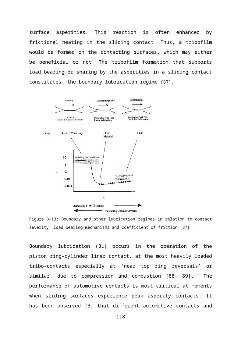
Figure 5-34: Variation of hardness of flat samples A10 and A11 respectively
Figure 5-35: Wear variation with hardness of the two sides of flat samples (a) A10 and (b) A11.
The non-homogeneity of the EN-GJL-250 material hardness is even clearer with the flat
sample A7 shown in Figure 5-13. The hardness variations introduce some challenges in
explaining the evolving wear scenario. Vicker’s hardness tests, with indentations around wear
scars help to further understand how the flat sample wear is dependent on hardness. The
effects of NPs additives in oil seem very small. However, the variation in hardness of the flat
sample across the surface and around the wear scar is a thing of concern. This may affect the
lubricating mechanisms of the lubricant.
118
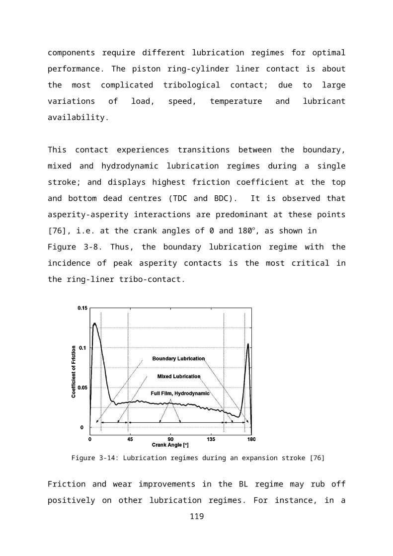
Figure 5-36: Hardness of the two sides of a flat sample, A7 (a) and the corresponding WSW (b).
Although most studies have assumed homogeneous hardness of contact samples, this is not
the case in this investigation. Another likely reason is the very high normal load of 40 N, with
a Hertzian contact pressure more than 3 GPa. The high load made the wear situation very
severe for the materials and lubricant combination used. This situation was reviewed in the
subsequent HFRR tests.
5.8 Wear Scar Morphological Examination
Naked eye analysis of wear scars show features that can be used to infer the mechanisms
involved in the wear related surface plastic deformation and degradation processes.
Generally, scuffing, ploughing and micromachining are wear mechanisms observed on the
flat samples. The flat samples subjected to tests at elevated temperature have deeper worn-out
grooves, compared to those of tests at RT. Metal-metal contact occurs in the boundary
lubrication sliding situation. Thus, visible wear scars are on all flat samples. The high
concentration of wear particles darkened the colour of the oil (in oil bath), compared to the
initial light colour of lubricants.
It was observed that rapeseed oil and rapeseed oil with the NPs additives at RT and 100oC
generated a larger amount of wear particles, compared to mineral oil and mineral oil with the
NPs. This can be due to the actions of FM and AW additives present in the fully formulated
mineral oil. The material damage is observed to be cumulative over the running time of each
test. The flat sample material is softer than the ball material. Thus, a significantly larger wear
is expected on the flat samples.
119
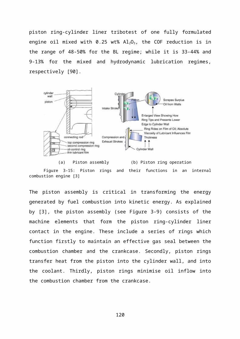
The wear scar characterisation was carried out with the use of the optical microscope (OM)
ZEISS Axio Imager .A1m. The micrographs of wear scars were taken around the middle of
the wear scar, along the sliding direction, consistently for the flat samples. The mid-way
position along the sliding path was expected to show a stable state of the major wear pattern.
The two ends (reciprocating motion) which experience repeated reversals, show an unstable
wear scar morphology.
Grooves are seen on most wear scars. The Extended Focus Acquisition mode was used to
acquire images on the microscope. At best fit, the images of the hollow scars were collected.
The less significant wear of the ball is also analysed with the OM. Typical unworn surface
images of the ball and flat samples are as shown in Figure 5-14. The micrographs of the wear
scars on both ball and flat samples explain the subsisting wear mechanisms in the contact.
They also show that NPs lower wear more at RT than at 100oC.
Figure 5-37: Typical images (x20) of the unworn surface of (a) ball and (b) flat samples
5.8.1 Wear Mechanisms on the Flat Sample
The wear surface images of the flat samples explain the associated wear mechanisms in the
sliding contact. For rapeseed oil and rapeseed oil with the NPs additives at 100oC; the major
wear mechanism is abrasion as shown in Figure 5-15. There are several wear mechanisms,
like adhesive welding-ploughing-shearing process, cyclic fatigue and micromachining in the
contact. This is shown on the wear surface. The WSW is slightly longer for rapeseed oil with
NPs additives, as shown in Figure 5-10, signifying possible abrasion along with other surface
damage mechanisms.
120
(b)(a)

Figure 5-38: Typical optical micrographs (x20) of wear scars on flat sample lubricated with:
(a) Rapeseed oil and (b) Rapeseed oil with the NPs at 100oC
The micrographs shown in Figure 5-16 show that NPs reduce wear in mineral oil at elevated
temperature. More abrasive wear was found on the contact lubricated with mineral oil than on
that lubricated with mineral oil and NPs additives. The slide-to-roll NPs lubricating
mechanism may contribute to the reduction in the mean WSW for mineral oil-NPs mixture as
shown in Figure 5-10.
Figure 5-39: Optical micrographs (x20) of wear scars on flat sample lubricated with:
(a) Mineral oil and (b) Mineral oil with NPs additives at 100oC
Scratch lines indicate abrasive wear on the flat samples lubricated with rapeseed oil and
rapeseed with NPs additives as shown in Figure 5-19. The abrasive lines are observed to be
fewer on the flat sample of the contact lubricated with rapeseed oil and the NPs additives.
The NPs in rapeseed oil constitute third body load support or/and nano-bearing mechanisms
in the tribo-contact. The nano-bearing mechanisms change sliding to rolling within the
contact, thereby reducing both the COF and wear. This partly explains the 32.4 % reduction
in mean WSW for the contact lubricated with rapeseed oil and NPs compared with that of
rapeseed oil only.
121
Adhesive wear
Grooving and abrasion
(b)(a)
Motion
Abrasion
(b)(a)
Abrasive lines
Figure 5-40: Optical micrographs (x20) of wear scars on flat friction coupon after tests with:
(a) Rapeseed oil and (b) Rapeseed oil with NPs at RT
The contact lubricated with mineral oil and NPs additives at RT show lower wear than that of
mineral oil only as shown in Figure 5-18. The NPs reduce wear in the tribo-contact by up to
37.4 % (WSW) compared to mineral oil only. NPs can fill the asperity valleys and form
tribofilm to support load. More than one NP lubricating mechanism could co-exist in the
contact.
Figure 5-41: Optical micrographs (x20) of wear scars on flat friction coupon, after tests with:
(a) Mineral oil and (b) Mineral oil with NPs additives at RT
5.8.2 Wear Mechanisms on the Ball Sample
Although the major wear mechanisms are expected to be observed on the flat sample, the ball
also shows surface damage. The optical micrograph of ball after test with a lubricant is
therefore necessary. As usual, the harder material in the tribo-pair would experience material
transfer, while the softer experience surface material removal. Some ploughed and transferred
materials from the softer would bond to the harder sample. These images show some
differences in the surfaces of balls with respect to lubricant.
122
AbrasionAbrasion
(b)(a)
Adhesive wearAdhesive wear
(b)(a)
The ball in the tribo-pair lubricated with rapeseed oil has some material transfer layer, as
shown in Figure 5-19. The material removed from the flat sample, are transferred to the ball.
However with rapeseed oil-NPs mixture, the layer spalls off and seem as third bodies, thereby
promoting abrasion. This partly explains the slightly higher mean WSW with rapeseed oil-
NPs mixture.
Figure 5-42: Typical optical micrographs (x10) of balls with lubricant: (a) Rapeseed oil and
(b) Rapeseed oil-NPs mix at 100oC
Figure 5-43: Typical optical micrographs (x10) of ball with lubricant: (a) mineral oil and
(b) Mineral oil-NPs mix at 100oC
At 100oC, mineral oil with the NPs additives reduces wear slightly compared with mineral oil
only (Figure 5-10). This equally shows on the corresponding ball specimen. Two-body
abrasion is dominant in rapeseed oil at RT shown in Figure 5-21(a). The abrasion in mineral
oil lubricated contact reduced to some kind of polishing with mineral oil and NPs. But, the
NPs additives in rapeseed oil reduce abrasive wear as shown in Figure 5-21(b), in agreement
with the lower WSW (see Figure 5-10).
123
Motion
Third-body
abrasives
Material transfer layer(b)(a)
Mild abrasion Burnishing
(b)(a)
Figure 5-44: Typical optical micrographs (x10) of ball with lubricant: (a) rapeseed oil and
(b) Rapeseed oil-NPs mix at RT
Figure 5-45: Typical optical micrographs (x10) of ball with (a) Mineral oil and
(b) Mineral oil-NPs mix at RT
Some NPs can fill the worn patches and reduce wear as explained by Lee [94]. At RT, the
NPs additives in mineral oil reduce the COF slightly, while wear reduction is significant in
the tribo-contact at 37.4 %. Therefore, the NPs can improve the tribological performance of a
lubricant in synergy with existing additives; similar to the findings of Aldana [16] and
Tomala [17]. This suggests that NPs can improve the performance of fully formulated engine
lubricants.
124
Lower AbrasionAbrasive lines
(b)(a)
Material
transfer
Material
transfer
(b)(a)

5.9 SEM/EDX Chemical Analysis of Wear Surface
The SEM/EDX analysis on the flat samples in the contact lubricated with rapeseed oil-NPs
mixture at 100oC, compared with that of the unworn surface is shown in Figure 5-23. These
revealed that the NPs do not form a tribofilm on the wear surface under the very high normal
load of 40 N. In both cases, the spectra of the wear surface and the unworn surface have
similar elemental chemistry. The presence of silica is not shown because oxygen, O is not
present on the -wear surface along with silicon, Si in Figure 5-23(a). This implies that under
the sliding conditions, NPs in a biolubricant like rapeseed oil would not form tribofilms on
the contacting surfaces.
Figure 5-46: Wear surface (a) and unworn surface (b) of the flat sample lubricated with rapeseed oil and the NPs
additives (RO + NPs) at 100oC, under a load of 40 N
125

Figure 5-47: Wear surface (a) and unworn surface (b) of the flat sample lubricated by mineral oil and the NPs
additives (MO + NPs) at 100oC and 40 N load
However, the case is a bit different for mineral oil mixture with the NPs. Traces of elements
of the NPs and lubricant additives like ZDDP are revealed on the wear surface, as shown in
Figure 5-24 (a), while such are not present on the unworn surface. This shows the synergy
between the NPs and the ZDDP in the fully formulated engine lubricant. The Polyvit is
presented as miscible with mineral oil based lubricants [145], but the lubricating mechanisms
of the NPs in biolubricants is not yet understood.
The aforementioned observations suggest a trial with lower normal load and contact pressure
of not more than 1 GPa. This would be within the usual range of load and contact pressure for
similar tribotests. Also, the conventional AW additive, ZDDP would be mixed with the
biolubricant along with the NPs to find if a synergy exists between ZDDP and the NPs
additives. The next tribotests use the suggested lubricant-additives mixtures. Both the HFRR
and the Universal Testing Machine (UMT) pin-on-disc tribometers were utilized for
characterisation of the lubricants under a load of 5 N.
126
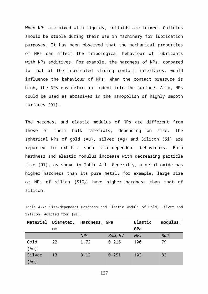
5.10 Conclusions
The HFRR tribotest in boundary lubrication conditions under a normal load of 40 N has been
described. The lubricants consist of a biolubricant (rapeseed oil) and a mineral oil lubricant
mixed with 0.1 wt. % of the NPs additives respectively. According to calculations of the
minimum film thickness and Lambda ratio, the test was conducted in the boundary
lubrication regime. This is a representation of the most severe lubrication challenge often
encountered by the piston ring-cylinder liner contact. The tests were held at RT and the high
temperature of 100oC, as close imitation of engine operating temperatures.
The TEM characterisation of the NPs shows the presence of the elements Si and O, which
implies that the NPs have a significant amount of SiO2. The friction behaviour of the NPs in
the lubricants was analysed, showing that the COF reduction by NPs is larger at RT than at
high temperature. The NPs was observed to increase COF by 4.5 % at high temperature
sliding when mixed with the biolubricant, but slightly reduce COF by 1.7 % when mixed
with mineral oil lubricant. Each of these COF reductions is with reference to the selected
plain lubricants.
The wear behaviour analysis is based on the WSW. While at RT the NPs reduced wear fairly
well (37.4 %) in mineral oil, it showed 7.5% reduction in the biolubricant. However, in high
temperature boundary lubrication sliding conditions, the NPs in the biolubricant caused an
increase in the WSW. When added to the mineral oil lubricant, a little wear reduction was
recorded. The wear mechanisms in the sliding contact include adhesive and abrasive wear
and material transfer.
Despite the excessively high normal load and severe wear damage to the surface, traces of the
elements of the AW ZDDP and the NPs are present on the wear surface of the flat sample
lubricated by mineral oil-NPs mixture. This suggested a synergy between the NPs and ZDDP
additives. Therefore, the addition of ZDDP to the biolubricant was proposed and tests
conducted in the subsequent experiments.
127
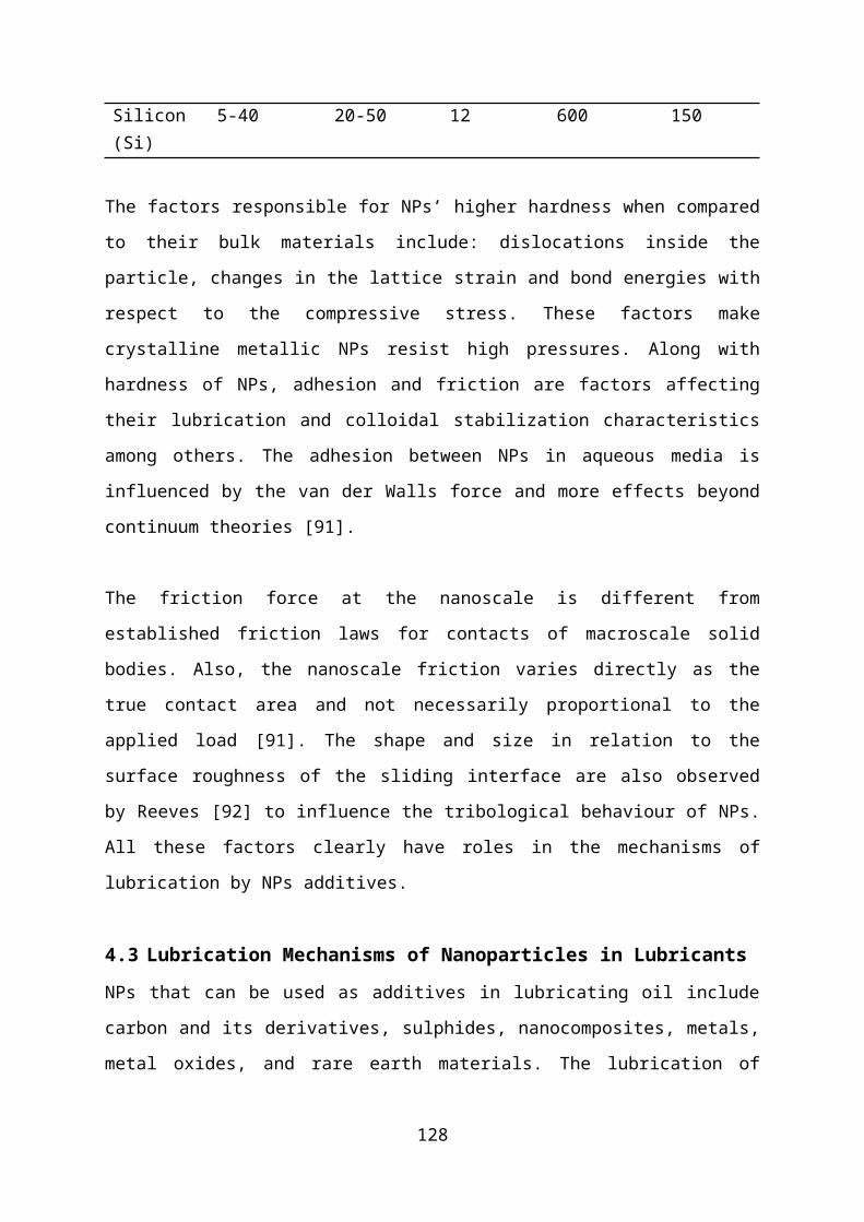
6 HFRR Tests with the Lubricants under a Load of 5 N
This chapter presents the HFRR tests under a load of 5 N. The lubricants were characterised
through the COF of the contact and flat sample WSW analyses. The wear scar profile and 3D
images are presented. The SEM/EDX is used to explain the occurrence of the elements of the
additives on the flat sample wear surface and the tribofilm lubricating mechanisms.
6.1 The Ball-on-flat Test under a Load of 5 N
The normal load of 40 N was rather too high in the earlier ball-on-flat tests leading to
excessive wear. The resulting high plastic deformation generated large amount of wear
particles. Thus, the expected boundary lubricating tribofilms were removed as deep cuts were
found on the flat sample. This made the surface chemical analysis rather difficult. The deep
cut made by the ball sample into the subsurface and bulk material of the flat sample around
contact area altered the sliding situation. It is therefore considered necessary to reduce the
normal load to 5 N resulting in an initial Hertzian maximum contact pressure of not more
than 1 GPa.
The ball-on-flat test on the Plint TE77 HFRR is repeated with some refinements and better
surface preparation to enhance the boundary lubrication adsorption process. The load of 5 N,
lower than 40 N, would keep the tribofilm, if any, from being removed during sliding. The
wear surface cleaning process is also reviewed regarding the cleaning agents employed.
SEM/EDX spectrochemical analysis would be used to detect the occurrence of either or both
of the NPs and ZDDP additive elements on the wear surface. The ZDDP is the AW agent in
fully formulated engine lubricant.
Some studies on the interaction of the well-known lubricant additive ZDDP with MoS 2 NPs
[17], and with WS2 NPs [16] have been reported. ZDDP is therefore considered for testing
with the NPs to understand their collaborative lubricating action. This stemmed from
128
observations in the earlier HFRR ball-on-flat tests at 40 N where the presence of the NPs in
the fully formulated mineral oil reduced both the COF and wear. The COF was lowered by
9.5% under RT sliding, and by 1.4% in sliding at 100oC as shown in Figure 5-9. Also, Figure
5-10 showed that the presence of the NPs in the mineral oil reduces the WSW by 12.5% and
37.4% at 100oC and RT respectively.
The procedure for the test under a load of 5 N is essentially similar to those of the earlier tests
under a load of 40 N. The adjustments made are in the areas of lubricant-additive mixtures,
which now include the ZDDP in rapeseed. Also, heptane is used for oil removal after test
with ultrasound for 60 s, to preserve the wear surface chemistry.
6.2 Test Materials
The ball sample, flat sample and the lubricants are briefly described for tribotest in boundary
lubrication regime under a load of 5 N, with lower speed and lower stroke compared to those
of earlier test under a load of 40 N.
6.2.1 The Ball and Flat Samples
The ball samples were used for tests as-received. The flat sample material is softer than
chrome steel ball. The description of the ball and the flat samples are as presented earlier in
Section 5.2.1 for the HFRR tests under a load of 40 N.
6.2.2 The Lubricants
Tests were conducted on lubricated contact with a fully formulated mineral oil (SAE
15W40), rapeseed oil and ZDDP, rapeseed oil-NPs and rapeseed oil, ZDDP and NPs
mixtures, respectively. The ZDDP concentration in the lubricants is 1 wt.%, while NPs are at
0.1 wt.%. Tests were carried out at RT (RT). The lubricant sample code and their respective
lubricant-additives composition are presented in the Table 6-1.
Table 6-13: The composition of the lubricants
Sample CompositionROO Rapeseed oil onlyRNP Rapeseed oil + 0.1 wt.% NPs RZD Rapeseed oil + 1 wt.% ZDDPRZN Rapeseed oil + 1 wt.% ZDDP + 0.1 wt.% NPs MOO Mineral oil or Fully formulated engine oil
129
MNP Mineral oil + 0.1 wt.% NPs
The AW ZDDP additive was supplied by Millers Oils UK. The ZDDP is a viscous liquid
material with amber colour. Some relevant properties as available on its safety data sheet are
flash point of 167oC, relative density of 1.2, and viscosity of 407.6 mm2/s at 40oC and 13.5
mm2/s at 100oC. The 1 wt.% addition to rapeseed oil is calculated to be 1.5 ml in 200 ml of
rapeseed oil. Also, the 0.1 wt.% of the NPs is 180.6 mg in 200 ml of rapeseed oil or 183 mg
in mineral oil lubricant. The properties of the NPs, rapeseed oil and the mineral oil engine
lubricant are as shown in Tables 5-2, 5-3 and 5-4 respectively.
6.3 Spectrochemical Analyses of the Lubricants
The elemental chemistry of the lubricant shown in Table 6-1 was determined. The tests were
carried out at The Oil Lab Ltd. Lancashire, UK. The lubricants were re-agitated by ultrasound
for 30 minutes before being packaged and sent for spectrochemical analysis. A volume of 50
ml of each lubricant was made available to the laboratory in their customised analysis bottle.
The results are shown in Table 6-2.
Table 6-14: Chemical composition of the lubricants
Elements (ppm) ROO RNP RZD RZN MOO MNPIron 0 0 0 0 1 2Aluminium 0 0 0 0 3 4Molybdenum 0 1 0 0 167 131Copper 0 0 0 0 0 1Lead 0 0 1 1 0 0Silicon 3 258 5 330 3 110Sodium 2 1 1 1 6Boron 0 0 0 0 43 36Calcium 6 28 7 6 2825 2917Phosphorous 14 21 1227 1259 695 675Zinc 12 7 1380 1429 781 757Magnesium 0 0 0 0 32 9
The metallic element present in the NPs is mainly silicon. Elements in the rapeseed oil and
NPs mixture are shown in the second column (from the left) in Table 6-3. In the mixture of
the rapeseed oil and NPs (RNP), silicon is 258 parts per million (ppm). The three mixtures
with NPs show the presence of silicon as a common factor. Silicon counts for 330 ppm in the
130
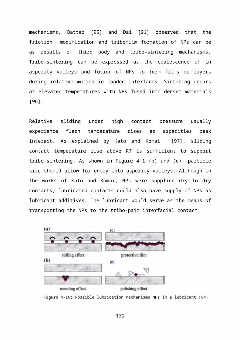
mixture of rapeseed oil, NPs and ZDDP, while it stands at 110 ppm in the mixture of mineral
oil and NPs.
The mixture of rapeseed oil and ZDDP shows insignificant amount of silicon, but the
presence of phosphorous and zinc in 1227 and 1380 ppm, respectively. Compared with
phosphorous and zinc contents in mineral oil, the ZDDP contents in its mixtures with
rapeseed oil are higher. The phosphorous and zinc content from the ZDDP in rapeseed oil
mixtures are about double (ppm) of that in the mineral oil. The fully formulated mineral oil
contains many conventional additives as shown by the presence of molybdenum (167 ppm),
boron (43 ppm), calcium (2825 ppm), phosphorus (695 ppm), zinc (781 ppm) and magnesium
(32 ppm).
6.4 Test Methods
6.4.1 General Test Conditions
The experimental conditions for the linearly reciprocating ball-on-flat sliding wear test are
stated in Table 6-3. The test duration is 2 hrs. The contact pressure calculated for 5 N load
using the equations in Section 5.3.1 is 789 MPa, or 0.8 GPa as used in similar studies on
lubricant-NPs lubricating mechanisms [16, 110, 142]. The linear sliding speed is 0.02 m/s
with a short stroke length of 2.42 mm selected to ensure sliding in boundary lubrication
regime.
The test is conducted in a test cell where the HFRR tribometer is installed with a fairly stable
RT of about 20oC. Tests at RT would show evidence of NPs tribofilm on wear surface and
possible advantages for engine cold start. The 100oC tests utilize the heating system and
controls on the HFRR tribometer. As in the earlier test, the NI LabView DAQ system is
utilized to collect and display the friction force measurements.
6.4.2 Surface Preparation and Cleaning
The Surface preparation processes of grinding and polishing were carried out on the flat
samples for lower average roughness, Ra. Some abrasive papers and polishing clothes were
used on a grinder/polisher to obtain a mirror finish surface. This would facilitate the
monitoring of tribofilm formation by ZDDP and the NPs in the contact. Typical flat sample
131
Ra of 0.035 – 0.090 µm is reported with good wear surface tribofilm formation [16, 143]. The
flat samples were polished in several grinding and polishing steps, cleaned with acetone and
isopropanol and dried with a metallurgical dryer.
Table 6-15: HFRR ball-on-flat experimental conditions
Test conditions Parameter ValueTest duration 2 hrs Normal load 5 NContact pressure 798 MPaStroke length 2.42 mmMotor speed 40 rpm (Set to 32 on Plint TE77).Linear sliding speed 0.02 m/s Motor frequency 5 HzTemperature RT, 20 ± 2oC (RT) Ball (upper test piece) AISI52100Flat (lower test piece) EN-GJL-250Total distance travelled 151 mTotal number of cycles 34000
The surface Ra of flat samples is in the range 0.03 – 0.10 µm. In the process of surface
preparation, it was observed that the flat sample should be washed with isopropanol
immediately after washing with water. Trying to dry sample after washing with water
allowed for corrosion to set in. But, warm drying after washing with isopropanol kept the
surface from corrosion or rust. Also, care should be taken while using the polishing wheel.
Low hand loading is better as this keeps the sample available for easy pick up. Higher
loading makes sample adhere more to the polishing cloth, and such could hurt the fingers or
throw off the sample. Some samples were damaged during polishing due to this error.
6.4.3 The Test Procedure
The test program is as shown in Table 6-4 below, for the lubricants at RT. However, for
characterisation of wear surface features especially for rapeseed oil mixtures with the
additives, selected tests were conducted at the higher temperature of 100oC. The wear scar
morphology and wear surface chemistry are the reasons for these selected tests. The flat
samples are labelled for clarity alongside their respective ball samples. The need for re-
agitation of lubricant-NPs mixtures is quite common in related studies [16]. Therefore, the
132
lubricant-additive dispersion was re-agitated with ultrasound for 15 minutes before being
used in the tribo-contact. This ensures proper dispersion of the NPs in the lubricant. Fisher
FB11020 ultrasound equipment with high frequency, 35 kHz was utilized.
The same ultrasound equipment was used for cleaning of the ball and flat samples for 20
minutes each in two solvents, acetone and isopropanol, making up 40 minutes of cleaning.
Basic laboratory rules for handling samples with protective gloves and others were observed
during the tests. After the tests the samples were cleaned with heptane and ultrasound for 60
seconds. The drop-feed lubricant supply technique was adopted and 3 ml pipette was utilized
to supply sufficient lubricant to the contact before the initiation of sliding motion. This is
representative of the starved lubrication conditions during combustion at the top dead centre
(TDC) [8].
The Lambda (λ) value for the tribo-contact was calculated using the equations in Section
5.3.2. This calculated values in Table 6-5 show that the test begins to run at the boundary
lubrication regime, i.e. λ < 1.
Table 6-16: Test program, flat sample and lubricant
Flat sample code LubricantC1 DryC2 MOOC3 MNPC10 ROOC5 RNPC6 RZDC8 RZN
Table 6-17: The minimum film thickness and Lambda ratio under the load of 5 N at 40oC
Lubricant Minimum film thickness, nm Lambda, λMineral oil 8.245 0.0187Rapeseed oil 3.131 0.0070
133
6.5 Results from Tribotests under the Load of 5 N
6.5.1 Coefficient of Friction
The mean COF is shown in the bar chart of Figure 6-1, while the friction evolution over time
in the HFRR test under the load of 5 N is shown in Figure 6-2. The addition of the NPs to the
fully formulated engine lubricant reduced the COF of the contact from an average of 0.17 to
0.15. This is similar to earlier observations in the test under a load of 40 N. The Polyvit NPs,
like WS2 and MoS2 NPs showed synergy with conventional additives in the engine lubricant
at RT. This is an advantage for engine cold start.
However, for rapeseed oil the NPs reduce COF compared with bare rapeseed oil. The NPs
and ZDDP together in rapeseed oil do not reduce COF compared with bare rapeseed oil and
mixture with each of ZDDP and the NPs respectively. Thus, with respect to COF at RT
sliding conditions, a synergy may not exist between the NPs and ZDDP in rapeseed oil or
biolubricant.
134
Figure 6-48: Coefficient of friction for the lubricants at RT under load 5 N
135
Figure 6-49: The evolution of friction for the lubricants at RT under a normal load of 5 N
136
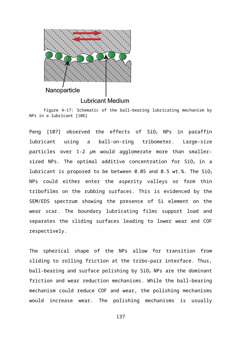
6.5.2 Results: WSW (WSW)
The optical microscope was utilized to obtain images of the wear scar on the flat sample. The
image is analysed and the WSW measured in three sections across, i.e. perpendicular to the
wear scar. The surface profilometer, used for larger WSW on flat samples under a load of 40
N, could not be used in this case because the wear scar is relatively small. The average of six
values of WSW from the OM image are analysed and presented in the bar chart of Figure 6-3
below. The NPs in rapeseed oil increase wear more than rapeseed oil only as lubricant for the
sliding contact. But the additions of ZDDP along with the NPs in rapeseed oil significantly
reduce wear. Thus, there is a synergy observed between the AW additive ZDDP and the NPs
in a biolubricant, to reduce wear under RT boundary lubrication sliding.
Figure 6-50: WSW on the flat sample in the ball-on-flat test at RT
The ZDDP additive in the biolubricant reduces wear more than the NPs additives. This shows
the well-known AW mechanism of the ZDDP at RT. The NPs addition to mineral oil has a
low impact on wear reduction. But the understanding of possible synergy between the NPs
and ZDDP for AW purposes is made clear, especially at RT.
137
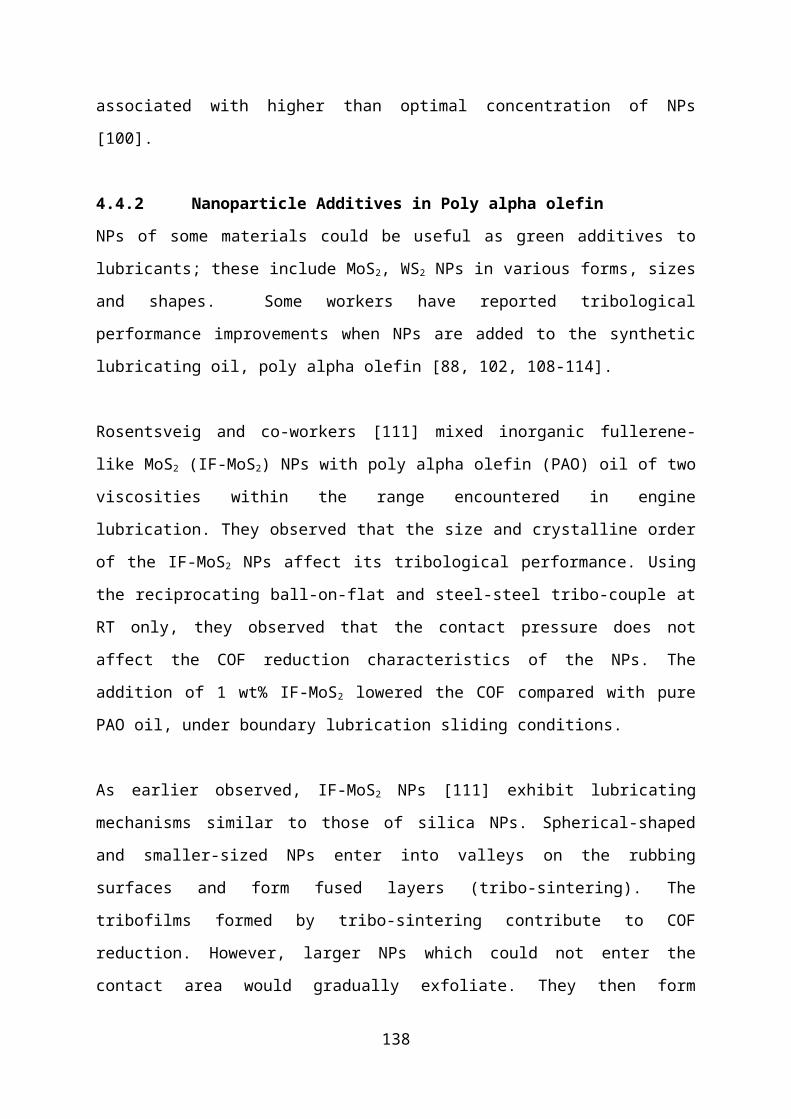
6.5.3 Wear Scar Profile and 3D Image
The profiles of the wear scar and their 3D images are taken with the Contour GT confocal
microscope. These data help to explain the wear situation and behaviour of the additives in
the lubricants, under boundary lubrication sliding and a load of 5 N, at RT. The behaviour of
the additives in the biolubricant (Rapeseed oil) can be inferred from the characteristic 3D
image and profile of the wear scar on the flat sample lubricated by each of the lubricants as
shown in Figure 6-4 below. The NPs alone in the lubricant exhibited the largest WSW,
followed by the rapeseed oil without any additive. This agrees with the WSW data shown in
the bar chart of Figure 6-3. Gara [105] observed a similar trend with ZnO NPs in lubricant
compared with lubricant without the NPs.
However, wear surface profile of the flat lubricated with rapeseed oil mixed with the ZDDP
(RZD), is similar to that of rapeseed oil mixed with both the ZDDP and NPs (RZN). See
Figure 6-4 (b) and (c). Thus, the synergy between the ZDDP and NPs cannot be observed
from here but from Figure 6-3, where it is shown as being significant, under RT boundary
lubrication sliding conditions. The NPs added to mineral oil can be observed to reduce wear
slightly as shown in Figure 6-5, under boundary lubrication sliding conditions at RT.
138
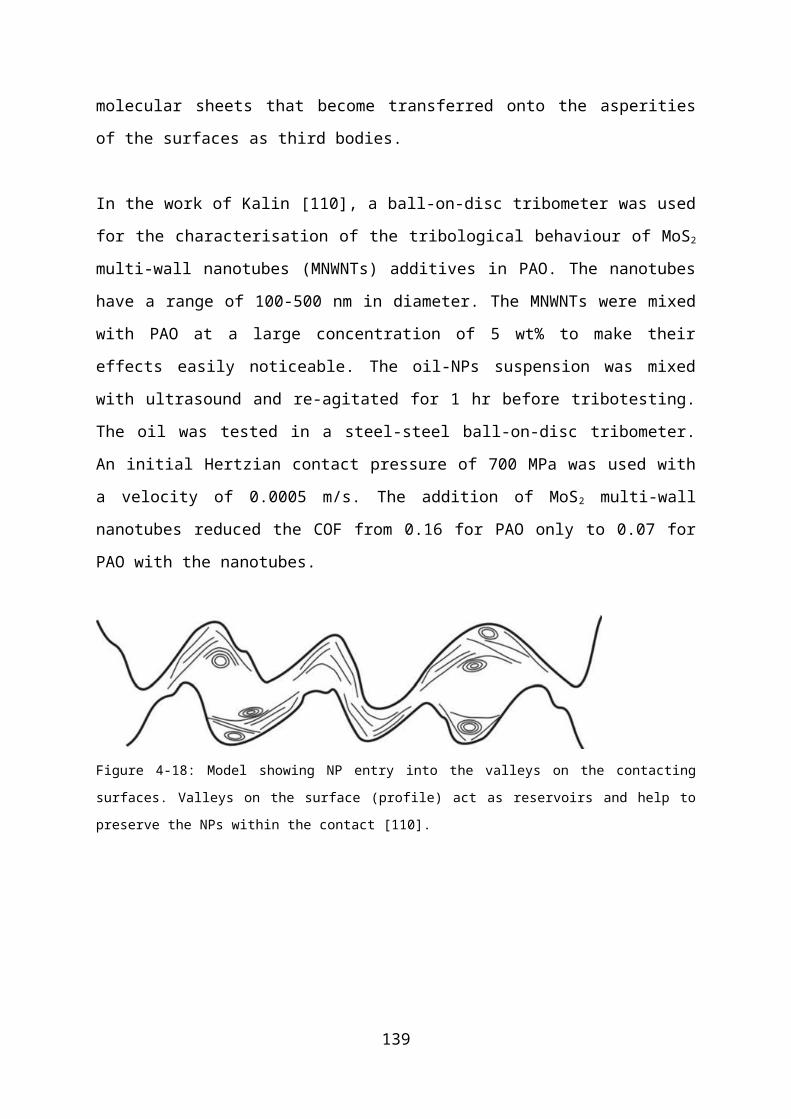
Figure 6-51: Wear surface image and profile on the flat sample lubricated with: (a) Rapeseed oil only, (b)
Rapeseed oil with the ZDDP and NPs, (c) Rapeseed oil and the ZDDP, and (d) Rapeseed oil and the NPs
additives; under 5 N load and boundary lubrication sliding conditions at RT.
139
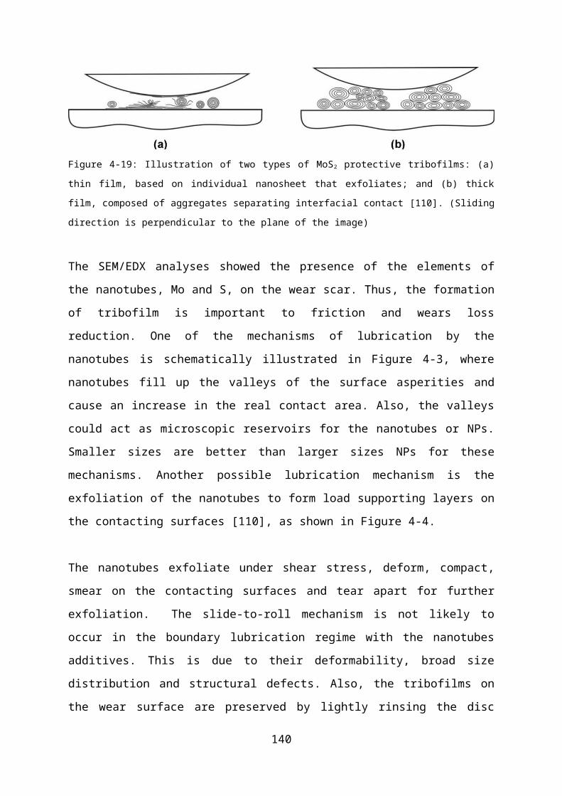
Figure 6-52: Wear scar image and profile on the flat sample lubricated with: (a) Mineral oil only, and (b)
Mineral oil and the NPs additives; under 5 N load and boundary lubrication sliding conditions at RT.
Some selected tribotests were conducted at 100oC to understand the behaviour of the
additives in biolubricant at a higher temperature. The lubricants selected for the 100oC
tribotest are: rapeseed oil with NPs (RNP), rapeseed oil with the ZDDP (RZD) and rapeseed
oil with both ZDDP and NPs additives (RZN). The HFRR tests at 100oC were done to be able
to understand whether the additives form tribofilms on the wear surface at the higher
temperature compared with what was obtained at RT.
The wear surface profiles of the flat sample lubricated by the three selected lubricants are
shown in Figure 6-6 below. The NPs in the biolubricant give a wider wear scar than the
ZDDP alone and ZDDP with the NPs additives at high temperature sliding. Also, there seems
not to be an advantage in adding the NPs and ZDDP to the biolubricant at high temperature
sliding. Thus, the ZDDP alone in the biolubricant is preferred for AW purposes in high
temperature boundary lubrication sliding conditions. However, from Figure 6-6, the duo of
ZDDP and the NPs have shown a lower WSW and depth profile compared with those of the
NPs alone in the biolubricant.
140
Figure 6-53: Wear scar image and profile on the flat sample lubricated with: (a) Rapeseed oil and NPs, (b)
Rapeseed oil and ZDDP, and (c) Rapeseed oil with ZDDP and NPs additives; tests were carried out under 5 N
load and boundary lubrication sliding conditions at 100oC.
141
6.6 Wear Surface Chemical Analysis
The cleaning of the wear contact after test was devised to preserve the evidence of tribofilm
formation. Instead of ultrasonic cleaning in acetone and isopropanol for a period of 10
minutes respectively, heptane is employed for 1 minute only. Heptane is more effective in
removal of oil traces from the surface of ferrous materials. This is to preserve the tribofilms
on wear surface for chemical analysis through the SEM/EDX.
The chemical analysis of the wear track is carried out to show the presence or otherwise of
the elements of the NPs and ZDDP on the wear surface of the flat sample. This would infer
the presence of a tribofilm composed of these additives in the contact. Tribochemistry play
a major role in understanding the boundary lubrication. The tribofilm can be formed on the
wear track through any one or more of these processes: tribo-sintering, chemical action,
adhesion, adsorption or any other NP lubrication mechanism.
In the SEM/EDX elemental analysis, silica can be evidenced on the wear surface by the
presence of the silicon (Si) and oxygen (O). The presence of Si only does not mean the
presence of silica. The C content shown in Figure 6-7(a) may be from the chemistry of the
rapeseed oil, because biolubricants are known to have long chain fatty acids with C=H
bonds and R–COOH groups that has affinity for metallic surface. But the ZDDP does not
form a tribofilm on ferrous material surface under RT sliding. This is shown in Figure 6-7(c)
by the absence of the elements of the ZDDP – Zn, S and P respectively on the wear surface.
The abrasive lines on the wear surface on the flat sample lubricated with rapeseed oil and the
NPs is evidence of abrasive wear action of the NPs on the contact as shown in Figure 6-7(b).
But the wear track of the flat sample lubricated with rapeseed oil, ZDDP and the NPs
mixture has the evidence of formation of the tribofilms made of both the NPs – Si and O, as
well as the ZDDP – Zn, S, and P. This agrees with observations of similar synergy between
ZDDP and NPs additives [16, 17, 142].
142
Figure 6-54: Wear surface morphology and chemistry for tests at RT with the lubricants: (a) Rapeseed oil only
(b) Rapeseed oil with the NPs additives, (c) Rapeseed oil with ZDDP and (d) Rapeseed oil with both ZDDP and
the NPs additives.
143
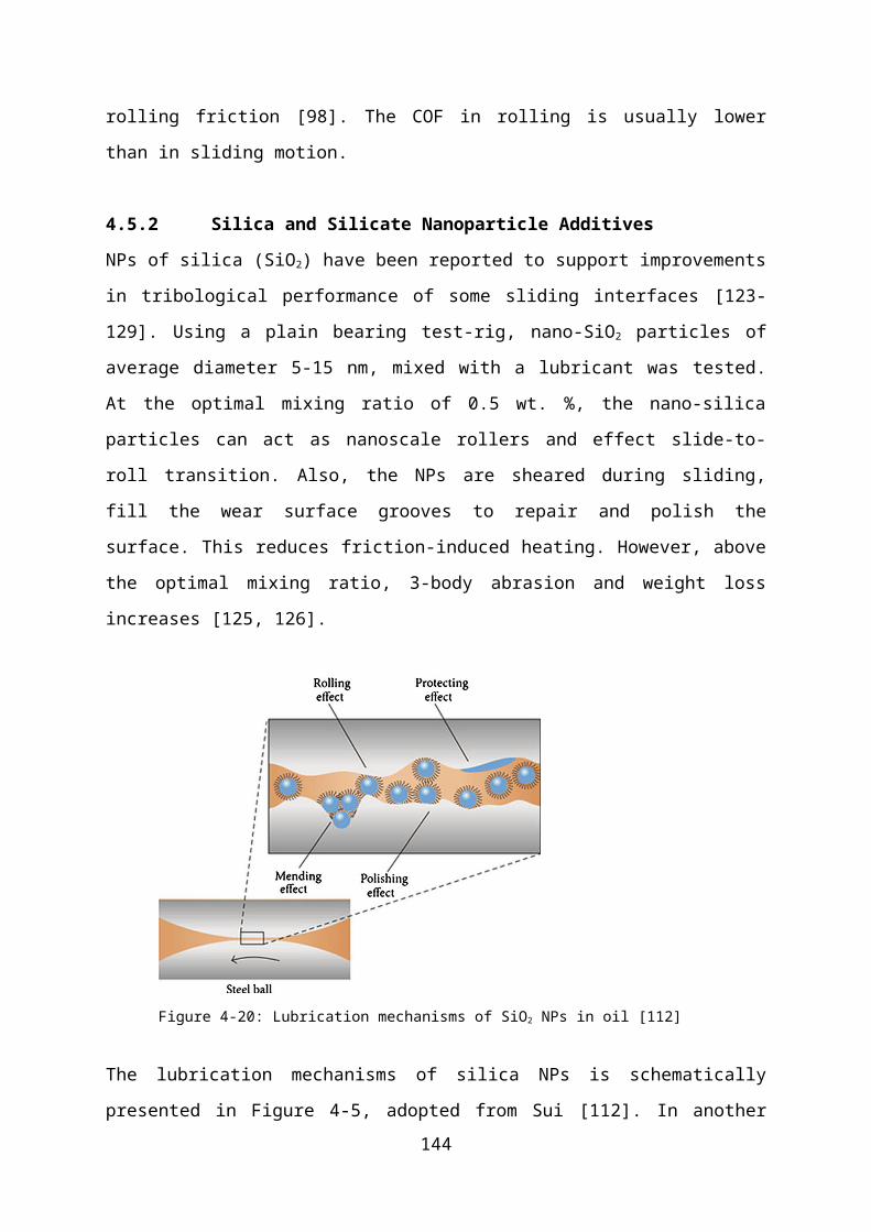
The wear surface lubricated with mineral oil and the NPs additives has the elements, Si and O
from the NPs present on the wear surface along with the elements, P, S and Zn from the
ZDDP usually present in fully formulated engine lubricant, SAE 15W40. This is shown in
Figure 6-8 (b). The surface lubricated with mineral oil only has the elements, P, S, and Zn
from the ZDDP as shown in Figure 6-8 (a).
Figure 6-55: Wear surface morphology and chemistry for tests at RT with the lubricants: (a) Mineral oil, (b)
Mineral oil and the NPs additives.
Silica is not on the wear surface lubricated by mineral oil only, because of the absence of O,
although Si is present. This Si could be a contaminant in the SEM. It is possible for the NPs
to work in a synergy with the conventional additive package, especially the ZDDP. Similar
synergy has been observed between conventional additives and NPs [142]. Both the NPs
and conventional additives can form boundary tribofilms together in a sliding tribo-contact,
but the friction and wear reduction advantages do not look very significant.
The selected tribotests at 100oC investigate possible tribofilm formation at a higher
temperature by NPs, ZDDP and both additives in the biolubricant. The wear surface
144
morphology and chemistry studies are for the tests with rapeseed oil and the NPs, rapeseed
oil and ZDDP and rapeseed oil and both ZDDP and the NPs as shown in Figure 6-9. The
wear surface exhibits a mix of wear mechanisms from mild adhesive wear on the surface
lubricated with rapeseed oil and ZDDP mixture (Figure 6-9(b) to severe ploughing and
material removal from the surface lubricated with rapeseed oil and the NPs mixture (Figure
6-9(a)).
Figure 6-56: Wear surface morphology and chemistry for tests at 100oC with the lubricants: (a) Rapeseed oil and
NPs, (b) Rapeseed and ZDDP, and (c) Rapeseed oil and both ZDDP and the NPs additives.
145
Delamination wear is present on the wear surface lubricated with rapeseed oil, ZDDP and the
NPs mixture, while abrasion can be observed on that of rapeseed oil and the NPs mixture.
This suggests that the NPs behave as abrasives and generate a deeper and wider wear scar as
can be seen on the 3D image in Figure 6-6(a) compared with (b) and (c). From the 3D image,
the wear depth and width on the flat sample are largest for rapeseed oil and NPs mixture at
high temperature sliding.
On the formation of tribofilms, the SEM/EDX spectra in Figure 6-9(a-c) show the elements
which are present on the wear surface lubricated by each lubricant. At high temperature,
boundary lubrication adsorption films are the lubrication mechanisms for wear reduction. The
elements of the NPs, Si and O can be observed on the wear surface lubricated with the
rapeseed oil and NPs mixture, Figure 6-9(a). The same scenario plays out for rapeseed oil-
ZDDP mixture and rapeseed oil-ZDDP-NPs mixture as shown in Figures 6-9(b) and (c)
respectively.
The wear surface lubricated with the rapeseed oil and ZDDP mixture has the elements of the
ZDDP: P, S and Zn, Figure 6-9(b). Also, the surface lubricated with the rapeseed oil, ZDDP
and the NPs mixture has the elements Si and O from the NPs as well as P, S and Zn from the
ZDDP, Figure 6-9(c). Although, it is not clear where the Si and O on the rapeseed oil and
ZDDP spectrum (Figure 6-9(b)) came from, but it can be suggested that the additives ZDDP
and the NPs can form tribofilm in boundary lubrication sliding at high temperature, when
added to a biolubricant.
6.7 Conclusions
The HFRR tribotest with the lubricant-NPs-ZDDP mixtures at room and high temperatures
were conducted under a load of 5 N in boundary lubrication sliding conditions. The
spectrochemical analyses of the lubricants show the elements of their additives. These were
also observed on wear surfaces with boundary lubrication tribofilms. The low load kept the
wear damage lower and allowed for tribofilm to be evidenced where available. The NPs
alone in the biolubricant and also in the mineral oil lubricant are suggested to reduce the COF
of the sliding contact under boundary lubrication sliding conditions.
146
However, the synergy proposed for the NPs and ZDDP AW additives is obvious when added
to the biolubricant. The rapeseed oil-ZDDP-NPs (RZN) lubricant exhibits the lowest WSW at
RT. This suggests that, as in other lubricant formulations, the ZDDP could work together
with the NPs in a biolubricant formulation. The 3D image and profile of the wear scar explain
the wear development more, such that the depth and width of the wear scars can be
compared. In support of the AW of the NPs-ZDDP synergy, the combination has the lowest
WSW and depth among the four biolubricant-based fluids. This, confirms a synergy between
the NPs and ZDDP for wear reduction in boundary lubrication sliding at RT which can result
in engine cold start advantages.
However, the NPs’ addition to the biolubricant that gave the lowest COF, in contrast, behaves
worst regarding WSW. This is a case of low COF and high wear co-existing in the same
tribological condition. But for the mineral oil lubricant, the NPs reduce both COF and wear,
although the COF reduction is more significant.
The wear surface analysis was used to understand the presence or absence of tribofilms on
the wear surface of the flat sample. The tests at room and high temperatures gave interesting
results. The following conclusions could be drawn:
The AW additive, ZDDP alone in biolubricant would not form tribofilms on the wear
surface in RT sliding;
The NPs alone in biolubricant exhibit abrasive wear. Although the elements of the
NPs are present on the wear surface, there is still severe wear;
The AW synergy between the NPs and ZDDP additives is confirmed by the presence
of the elements of both additives on the wear surface. This led to good wear
reduction, but COF increase. This scenario can be further investigated;
The NPs addition to mineral oil lubricant reduces both COF and wear. This affirms
similar observations with HFRR tests under a load of 40 N. One can propose that the
NPs addition to mineral oil could improve the tribological performance of the contact
at room and high temperatures.
At high temperature, the two additives: NPs and ZDDP; either singly or in
combinatorial mode, could form tribofilms on the wear surface.
147
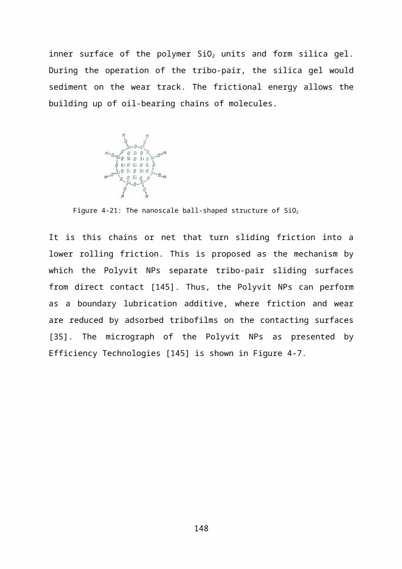
7 The Pin-on-Disc Unidirectional Sliding Test
This chapter consists of the pin-on-disc test for characterisation of the lubricants, to further
understand the effects of the Polyvit NPs on friction and wear. The ball and disc samples are
briefly described, while the lubricants are also described for the test on the Bruker UMT. The
tribological performances of the additives under unidirectional boundary lubricated sliding
are explained by the COF and wear rate analyses. The 3D images and wear track profile is
used to describe the wear situation.
7.1 The Pin-on-disc Test
The experiments were performed at RT on a Bruker UMT tribometer. The rotary module
provides the unidirectional sliding motion of the disc which is fixed in the oil bath, while the
ball sample is held stationary. The picture of the test set up is shown in Figure 7-1. The
standard procedure for the pin-on-disc tribotest, ASTM G99-05 (Reapproved 2010) was
adopted for the characterisation of the lubricants.
The reason for using this type of testing was to observe the impact of the sliding mode on the
tribological performance of the lubricants. The pin-on-disc UMT test was carried out in the
boundary lubrication regime as were the earlier HFRR tests. The normal load was 5 N as for
the unidirectional sliding test on the Bruker Universal Testing Machine (UMT). The wear
rate is based on the wear track width and sliding distance over a 3 hour test period. The wear
surface features and chemistry is analysed with the Contour 3D and SEM/EDX microscopes.
148
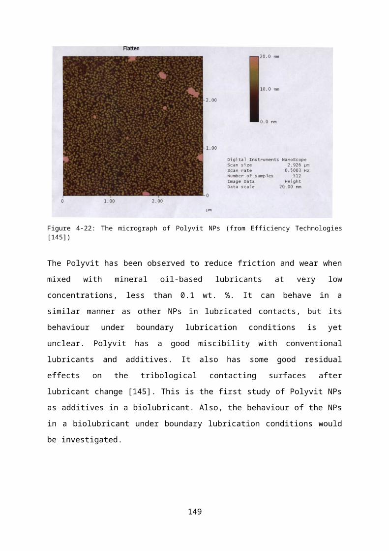
Figure 7-57: The UMT pin-on-disc tribotest set-up
7.2 Materials and Test Conditions
7.2.1 The Ball and Disc Samples
The G10 AISI 52100 balls with a diameter of 6 mm and Ra of 0.025μm were procured from
Atlas Ball and Bearing Co. Ltd. UK. They were used as-supplied, being able to fit into the
upper stationary ball-holder on the UMT and behave as a spherical pin.
The EN-GJL-250 discs of diameter, 70 mm and thickness, 6.35 mm were machined. The
surface was ground and polished to Ra ranging between 0.02 and 0.09μm and Rq ranging
between 0.03 and 0.08μm.
7.2.2 The Lubricants
The biolubricant – rapeseed oil – was mixed with the two lubricant additives, ZDDP and the
Polyvit NPs. While the ZDDP concentration in lubricant is 1 wt.%, the NPs concentration is
0.1 wt.%. The ZDDP (zinc dialkyl dithiophosphates) AW additive is supplied by Millers
149
Oils, UK, while the Polyvit NPs are from Efficiency Technologies, UK. The TEM/EDX
chemical analysis of the NPs is discussed in Section 5.4. Table 7-1 shows the physical and
chemical properties of ZDDP. The compositions of the lubricants are as shown in Table 7-2
below. The composition of the lubricants used in the test is shown in Table 7-2, similar to
those of the previous test on the HFRR, under a load of 5 N.
Table 7-18: Physical and chemical properties of the ZDDP
AppearancePhysical state LiquidForm Viscous liquidColour AmberOdour Characteristic of sulphur-containing
compoundsFlash point 167oC (Pensky-Martens Closed Cup)Vapour pressure 0.0069 bar (25oC)Relative density 1.2 (15.6oC)Partition coefficient (n-octanol/water) 0.56 (Measured)Auto ignition temperature 264oCDecomposition temperature 222oCViscosity 13.5 mm2/s (100oC); 407.6 mm2/s (40oC)Pour point -3oC
Table 7-19: Lubricant composition for the UMT pin-on-disc tribotest
Lubricant CompositionROO Rapeseed oil onlyRNP Rapeseed oil + 0.1 wt.% NPsRZD Rapeseed oil + 1 wt.% ZDDPRZN Rapeseed oil + 1 wt.% ZDDP + 0.1 wt.% NPsMOO Mineral oil onlyMNP Mineral oil + 0.1 wt.% NPs
7.2.3 The Pin-on-disc Test Conditions
The general test conditions for the pin-on-disc test are shown in Table 7-3. The test duration
is 3 hrs at a very slow speed to ensure boundary lubrication sliding conditions. The load of 5
N, with the Hertzian contact pressure calculated as 798 MPa is considered good enough as
used earlier in the HFRR. The consistency also allows for fair comparative analysis.
150
Table 7-20: General test conditions for the pin-on-disc test
Test conditions for the UMT pin-on-disc tribotestParameter ValueTest duration 3 hrs Normal load 5 NContact pressure 798 MPaSpeed 0.003 m/s Temperature RT, 20 ± 2oC (RT) Ball (upper test piece) AISI52100, Dia. 6 mmDisc (lower test piece) EN-GJL-250, Dia. 70 mm
7.3 Results and Discussion: Pin-on-disc Tribotest
The coefficient of friction, COF of the contact and wear rate of the disc are analysed from test
data. These provide the basis for discussion of the tribological behaviour of the lubricants,
especially the additives being studied.
7.3.1 Coefficient of Friction
The COF versus sliding time plots for the rapeseed oil-based lubricants are shown in
Figure 7-2. As it is common with biolubricants, the fatty acid constituent has affinity for
metallic surfaces in a tribo-pair. This explains why rapeseed oil only has the lowest COF over
time of sliding at RT. Compared to other lubricant compositions based on rapeseed oil, the
plain rapeseed oil gives the best COF.
151
Figure 7-58: Typical COF versus time curve for: (a) Rapeseed oil and NPs (RNP), (b) Rapeseed oil and ZDDP
(RZD), (c) Rapeseed oil, ZDDP and NPs (RZN), (d) Rapeseed oil only (ROO) and (e) the four lubricants
compared
152
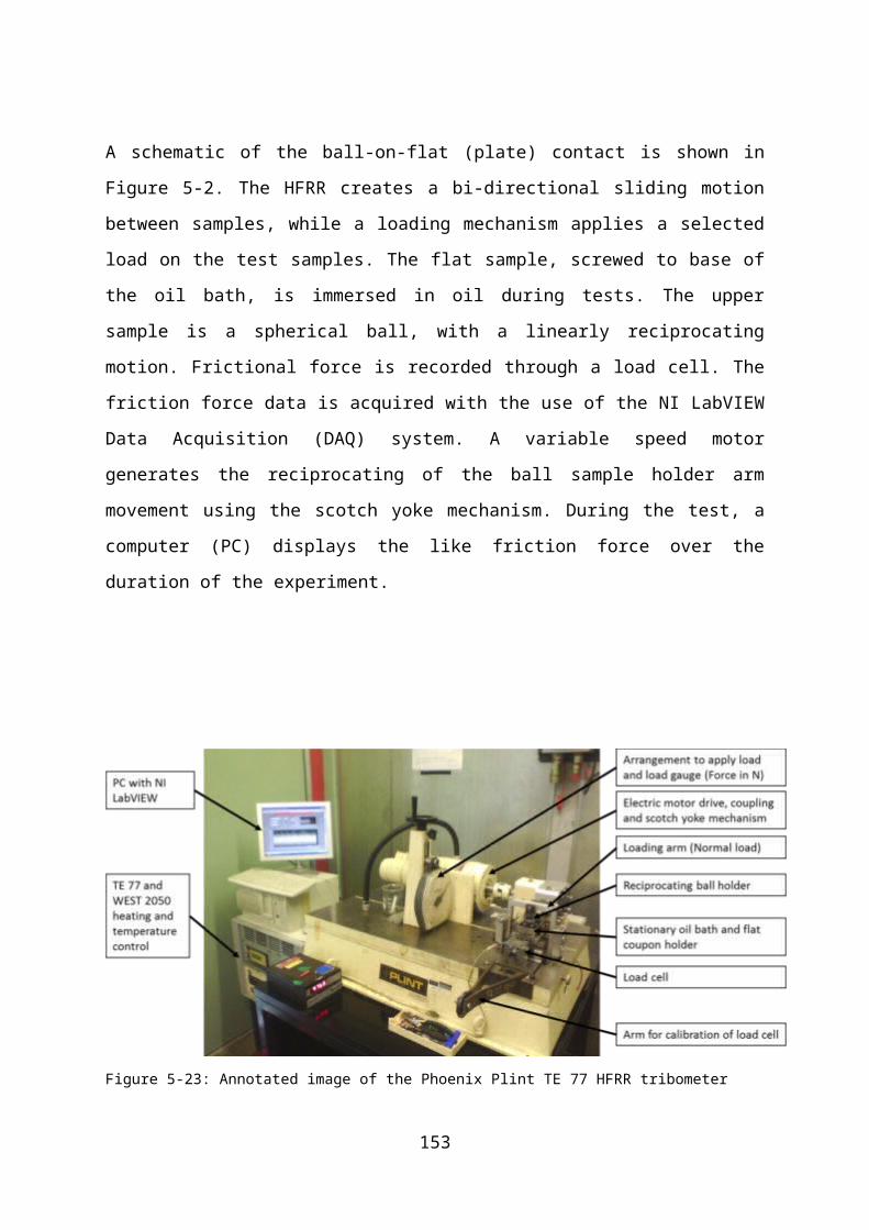
Figure 7-59: COF versus time curve for the lubricants (a) Mineral oil only and (b) Mineral oil with the NPs
additives; (c) the combination of (a) and (b).
The effect of the NPs on COF is shown in Figure 7-3. In the unidirectional sliding conditions,
the lubricant-NPs mixtures do not behave better than the plain lubricants in the tribo-contact.
This is opposed to the observations in the HFRR test in which the NPs exhibit friction
reduction compared to mineral oil only. The bar chart of Figure 7-4 shows an 8.34 %
increase in COF due to addition of the NPs to the mineral oil engine lubricant.
153
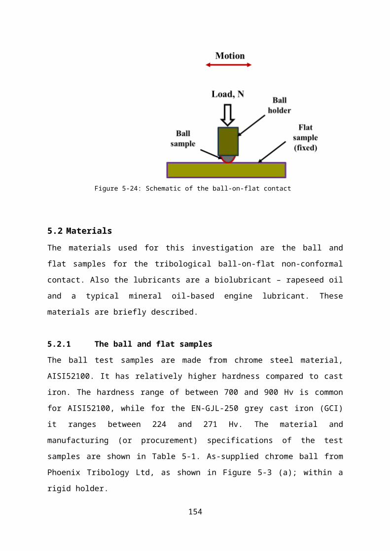
Figure 7-60: Coefficient of friction for the lubricants in the pin-on-disc test
All the additives in rapeseed oil enhance increments in COF as shown in Figure 7-4. The
ZDDP increased COF by 7.20 % compared to rapeseed oil only. The NPs increased the COF
by a similar margin, while the two additives used together tend to lower the severity of COF
increase. The two lubricant additives working together increased COF by 5.04 % compared
to rapeseed oil only.
7.3.2 Wear Rate Analysis
The ASTM G99-05 (2010) proposed the equations for calculating the disk wear volume with
no significant pin wear. The spherical pin (stationary ball) is made from a harder material,
AISI 52100 steel compared with the EN-GJL-250 grey cast iron. In agreement with the
Archard wear law, wear is more significant on the softer surface than on the harder surface in
a sliding tribo-contact. So, the pin is assumed to have little or no wear for wear rate analysis.
The sliding wear volume loss would be more significant on the disc surface than on the ball
surface. Thus the wear volume loss equation for no significant pin wear situation is
considered appropriate.
The wear track width on the ball is difficult to measure with the optical microscope. This is
due to the shining mirror-finish surface of the ball. Also, the reflective surface of the disk
restricts imaging to low magnifications on the microscope, up to 10x limit. The Contour GT
microscope was used for wear surface 3D image and profile on the disc. The equation for
154
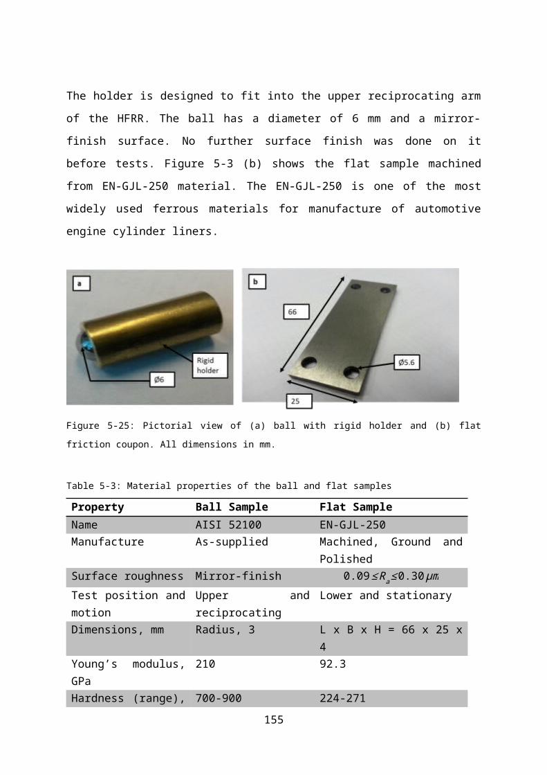
calculating disc wear volume loss, assuming no significant pin wear as given by the ASTM
G99-05 is:
Disc volume loss ,mm3 ¿ π (wear track radius , mm)¿¿
Equation 7-28
This is an approximate geometric relation that is correct to 1% for (wear track width/ball
radius) < 0.3, and is correct to 5% for (wear track width/ball radius) < 0.8.
The calculated (wear track width/ball radius) ratio is in the range of 0.080 to 0.269, less than
0.3 as required for the use of Equation 7-1. Wear track width measurements on each disc
were taken from three locations on an optical micrograph of the wear track as shown in
Figure 7-5, and the mean reported.
Figure 7-61: Typical optical micrograph used for wear track width and wear rate calculations. Lubricants: (a)
Rapeseed oil only. (b) Rapeseed oil and ZDDP, (c) Rapeseed oil and NPs, (d) Rapeseed oil, ZDDP and NPs, (e)
Mineral oil only and (f) Mineral oil and NPs
The optical micrographs of the EN-GJL-250 grey cast iron flat samples in Figure 7-5 can be
used to explain the variation in hardness of the material. This is largely influenced by the
microstructure. The finer the microstructure, the harder the material. Thus, the sample in
Figure 7-5 (b) can be observed as interdentritic graphite plates while that in Figure 7-5 (d)
shows pearlitic graphite plates. It is necessary to select flat samples of similar microstructure.
155

This would minimise the variation in hardness and tribological properties. The mechanical
and tribological properties of grey cast iron depend on the microstructure [144][145].
The mean wear track width is used to calculate the wear volume loss, based on Equation 7-1.
The wear rate is calculated as the ratio of the wear volume loss and the sliding distance. The
wear rate or specific wear rate is a measure of the amount of material loss over the sliding
distance.
Wear rate= Wear volume , m3
Sliding distance , mEquation 7-29
The sliding speed is 3 mm/s or 0.003 m/s, and the duration of test is 3 hours or 180 minutes.
As the sliding speed is converted to RPM appropriately for each sliding radius of the disc, the
linear speed remains the same for all the tests. Thus, the sliding distance is calculated:
Slidingdistance=Slidingspeed × Durationof test
Slidingdistance=0.003 ×180 × 60=32.4 meters
The average WSW is used to calculate the wear rate based on the standard formulae. The
wear rate values are shown in Table 7-4.
Table 7-21: Wear rate of the UMT disc
Lubricant Wear Track Width, mm
Wear Volume, mm3
Wear Rate, m3/m
Rapeseed oil only 0.2630 1.2623 38.96017Rapeseed oil and ZDDP 0.2477 1.1887 36.68872Rapeseed oil and NPs 0.2500 1.1999 37.03438Rapeseed oil, ZDDP and the NPs 0.2487 0.8680 26.79044Mineral oil only 0.5240 2.7437 84.68079Mineral oil and the NPs 0.8073 3.8749 119.5964
The disc wear rate for contact lubricated by each of the lubricants is shown in Figure 7-6. The
wear volume loss over sliding distance for the two additives in rapeseed oil is the lowest.
This shows that the AW behaviour of the additives could be collaborative and advantageous
to metallic tribo-pairs as is the case with the automotive engine. The plain rapeseed oil that
156
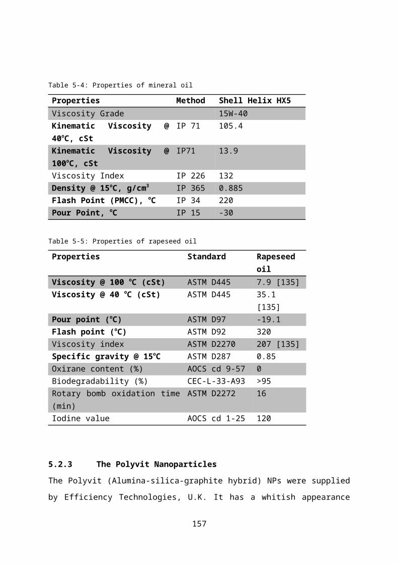
display the best COF reduction as shown in the COF bar charts of Figure 7-4 now behave
worst in terms of AW characteristics.
Therefore, at RT unidirectional sliding, the fatty acid in a biolubricant does not have AW
property. The ZDDP and the NPs appear to have similar friction and wear behaviours in
metallic contacts under boundary lubrication sliding at RT. Also, for unidirectional sliding,
the NPs have poor friction and wear performance in mineral oil lubricant based on the COF
shown in Figure 7-4 and wear rate shown in Figure 7-6.
Figure 7-62: Disc wear rate for the pin-on-disc tribotest under a load of 5 N
7.3.3 Wear Track Morphology: 3D Image and Profile
The 3D image and profile across the wear track is show in Figure 7-7 for the disc lubricated
with mineral oil (MOO) and with mineral oil and the NPs additives mixture (MNP). Abrasive
lines are in larger number on the disc lubricated with MNP than that of MOO. Also, the
WSW across the wear track for MNP is 0.104, more than 0.076 for MOO. Thus, abrasive
wear can be observed to impact much surface damage to the disc lubricated with MNP. But,
for that with MOO, plastic deformation can be by severe adhesive wear or ploughing and
material removal and/or transfer to the pin surface.
157
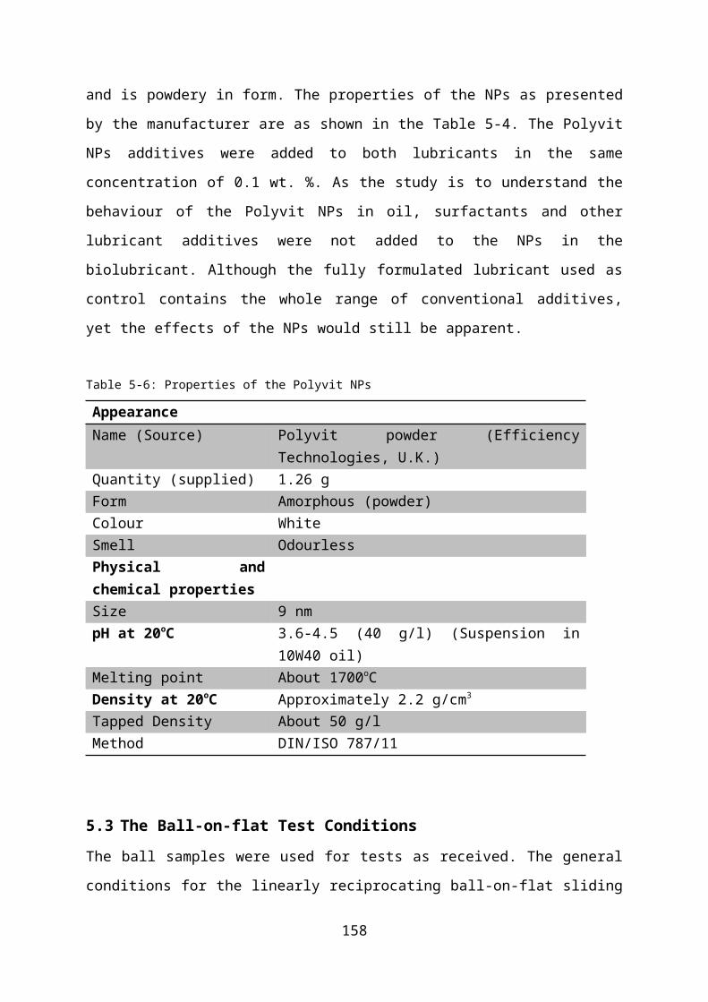
Also, the movement of materials to the edges of the wear track can be seen on the MOO
profile. The disc surfaces from contacts lubricated with the rapeseed oil-based lubricants
exhibit lower wear, both abrasive and ploughing, compared to those lubricated with mineral
oil. This observation agrees with the bar charts of the wear rate in Figure 7-6. As shown in
Figure 7-8, fair mixtures of abrasive and adhesive wear occur on the wear surfaces – from
mild for rapeseed oil-ZDDP mixture (c) to severe as in rapeseed oil mixture with both
additives (b).
Figure 7-63: UMT disc sample wear track images and surface profiles for contacts lubricated with (a) Mineral
oil only and (b) Mineral oil with the NPs; under similar boundary lubrication conditions.
It is observed that the wear track width does not consider the depth of cut or material removal
into the subsurface of the disc. This explains the differences between the 3D image and
profiles in Figure 7-8 and the wear rate bar charts of Figure 7-6 for the rapeseed oil-based
lubricants. The unidirectional test show the synergy between the NPs and ZDDP in wear
reduction. The biolubricant-ZDDP-NPs mixture exhibit the lowest wear rate compared to
biolubricant-ZDDP, biolubricant-NPs and the plain biolubricant. This agrees with the HFRR
WSW results in Figure 6-3. So, it can be proposed that the NPs could work in synergy with
ZDDP under low load, low speed boundary lubrication sliding at RT.
158
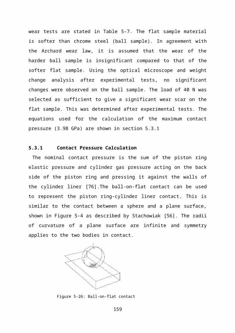
Figure 7-64: UMT disc sample wear track images and surface profiles on the flat sample lubricated with: (a)
Rapeseed oil only, (b) Rapeseed oil with ZDDP and NPs, (c) Rapeseed oil with ZDDP and (d) Rapeseed oil
with the NPs additives; under similar boundary lubrication conditions.
The biolubricant has shown a possibility of compatibility with either the NPs alone, or in
combination with the AW ZDDP. It is observed that the AW mechanisms of the ZDDP may
not have been hampered but rather enhanced by the NPs. Thus, biolubricant formulations can
utilize both additives together for wear reduction, more than when either is used alone.
159
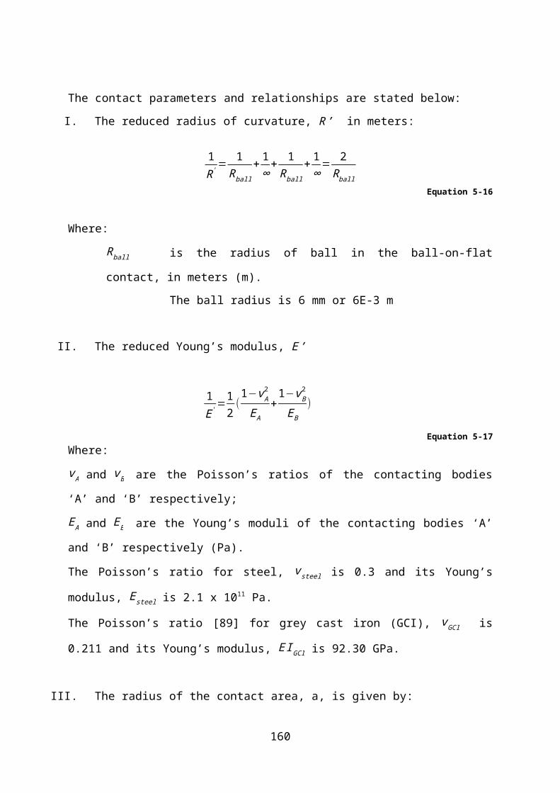
7.4 Conclusions
The Bruker UMT unidirectional tests gave results that are useful alone or in some cases can
complement the HFRR results. The behaviour of the additives in combination and alone in
boundary lubrication sliding conditions show that the plain lubricants perform better than
when the additives are added. This is for RT operation. However, the synergy proposed
between the NPs and ZDDP is observed to lead to COF lower than those of each of the two
additives alone in the biolubricant.
The wear rate results show similarities to the WSW analysis of the HFRR test under a load of
5 N. The two additives, the NPs and ZDDP, exhibit combined wear reduction mechanisms,
and give the lowest wear rate in the UMT tests. Therefore, the NPs and ZDDP additives can
have combinatorial wear reduction mechanisms. They are compatible with one another and
with the biolubricant for wear reduction in tribological contacts, such as the piston ring-
cylinder liner contact in the automotive engine.
160
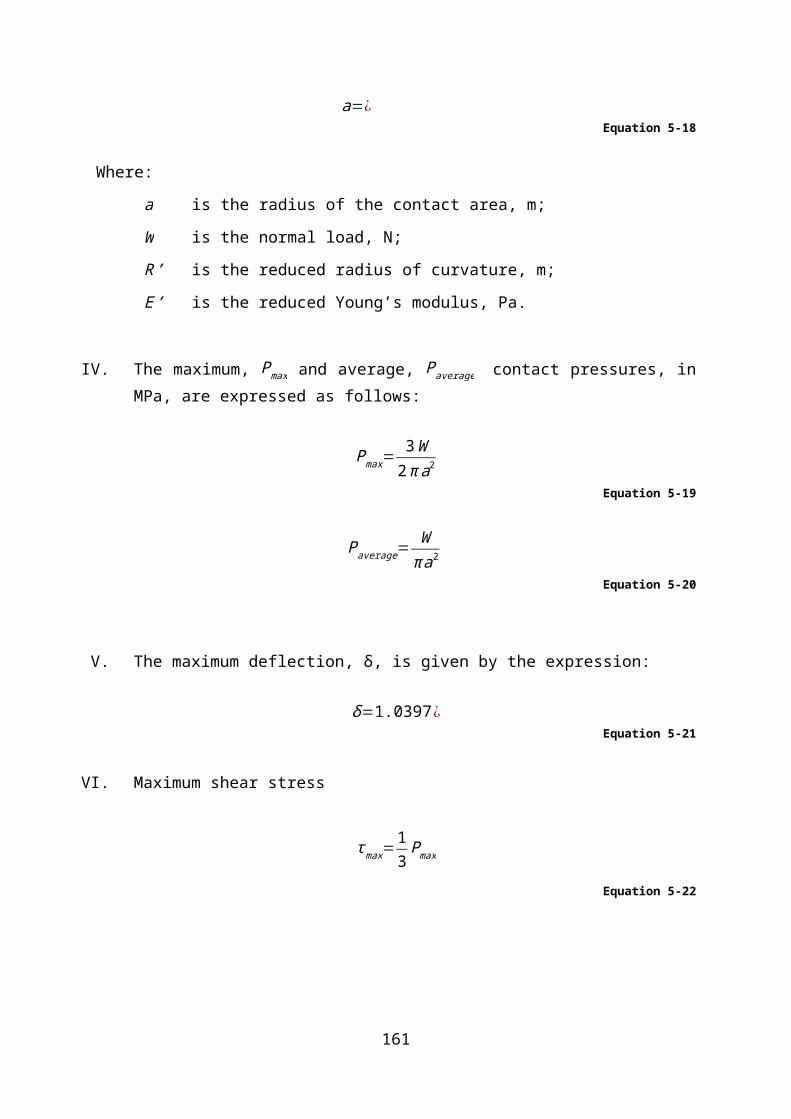
8 Conclusions, Reflections and Further Work
The potentials of NPs as lubricant additives were investigated. Performance characteristics of
the oil with NPs additives can support the next generation lubricant formulation. NPs may
compliment fully formulated oils, for longer oil-drain intervals and thereby save some
volume of oil from being added to the pollution pool. Also, the NPs can support biolubricants
for use in situations where biodegradability, toxicity and the environment are critical.
The Polyvit is a green lubricant additive. The benefits of Polyvit in lubrication of automotive
contacts will be further understood with use of other tribometers. NPs remain an additive
being explored for fluid lubricated systems. If NPs performance in the boundary lubrication
regime is satisfactory, then NPs may support low speed, high load and low temperature
contact situations in engines. These situations are often present in early (cold) engine starts.
NPs could work in synergy with existing additive packages. Boundary lubrication is about the
most challenging situation, where the metal-metal contact depends on tribofilms for lower
COF and wear reduction. The ball-on-flat test results have enabled some evidential
understanding of the Polyvit NPs addition to a biolubricant and fully formulated engine oil.
The Polyvit NPs show potential as a green lubricant additive.
The HFRR represents the reciprocating piston ring on stationary cylinder liner contact in the
automotive engine. The HFRR test under a normal load of 40 N was a learning curve taken in
the process of doing lubricant characterisation. As observed in the early parts of the study, 40
N (a contact pressure of over 3 GPa) is excessive and results in deep cuts into the flat sample.
A review of the normal load down to 5 N enable the analysis of the boundary lubrication
mechanisms under the SEM/EDX.
The Bruker UMT pin-on-disc unidirectional test showed the marked difference in COF and
wear parameters when the sliding contact’s motion changes. This implies that the behaviour
of a tribological contact should be compared under similar contact configuration and sliding
motion. Nonetheless, the results from one motion may agree or disagree with those from
another type of motion. The friction and wear behaviour of the lubricants also change
161
significantly with temperature. It is necessary to test the lubricants at the RT and a high
temperature of 100oC to imitate real-life engine operating conditions.
As observed from the tests, from the HFRR test under 40 N, the NPs reduce COF when
added to both the rapeseed oil (referred to as biolubricant) and the fully formulated mineral
oil lubricant at RT sliding conditions. But, while the NPs reduce the WSW when added to the
mineral oil, this advantage is not clearly seen with the biolubricant. Also, the COF evolution
over time is more stable when the NPs were added to the engine lubricant than that of the
plain mineral oil, under high temperature sliding conditions.
However, the biolubricant does not perform better with the NPs additives in high temperature
sliding. This is an indication of the need for conventional FM and AW additives for high
temperature engine operation in the biolubricant. When the normal load was reduced to 5 N,
the NPs reduce COF in the mineral oil lubricant and also in the biolubricant at RT. It is good
to note that the NPs reduce COF more that the plain biolubricant, as well as the biolubricant-
ZDDP and the biolubricant-ZDDP-NPs mixtures.
Although, the ZDDP-NPs synergy did not give a COF advantage, yet it shows the lowest
WSW, compared to the plain biolubricant, biolubricant-ZDDP and biolubricant-NPs
mixtures. But under a normal load of 5 N, the NPs in mineral oil slightly reduce the WSW.
The ZDDP in the biolubricant behaves as a good AW in agreement with literature. The 3D
images and profiles show that the biolubricant-ZDDP mixture reduces both the width and
depth of the wear scar, more than biolubricant-NPs and biolubricant-ZDDP-NPs mixtures.
The wear surface chemical analysis of the HFRR flat sample of test under a normal load of 5
N shows the evidence of the adsorption film or tribofilm. The tribofilm is one of the
mechanisms for COF and wear reduction in boundary lubrication sliding. The proposed
synergy between the NPs and ZDDP is shown in wear reduction, during sliding under a load
of 5 N. The elements of the NPs and ZDDP are present on the wear surface. This indicates
that the two additives can work together, when mixed with a biolubricant, for wear reduction
under RT sliding conditions but not so in COF reduction. A similar scenario plays out with
the NPs in mineral oil lubricant. So, the NPs alone or along with the ZDDP could reduce
wear in boundary lubrication sliding at RT.
162
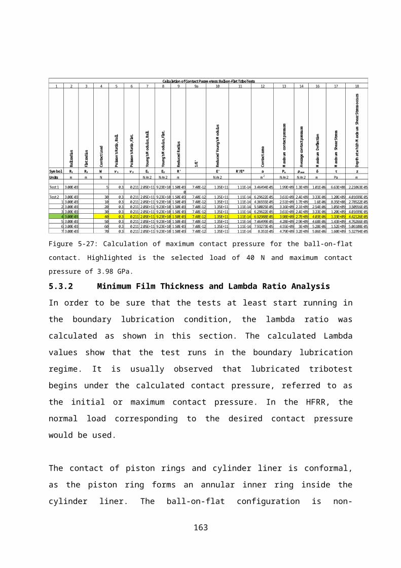
Interestingly, the ZDDP does not form tribofilm at RT but does so at high temperature
sliding. The elements of the ZDDP are evident on the wear surface of the flat sample
lubricated with the biolubricant-ZDDP mixture under boundary lubricated sliding at high
temperature. The 3D image and profile of the wear scar supports the proposal that ZDDP
alone can be the AW additive in a biolubricant for boundary lubricated sliding at high
temperature conditions. Albeit, the NPs-ZDDP combination lowers wear more than the NPs
alone. This is corroborated by the situation with mineral oil-NPs behaviour at high
temperature sliding under 40 N.
The study selected two tribometers – the HFRR and the UMT – for lubricant-NPs-ZDDP
characterisation. This was done at RT and 100oC. The wear surfaces were analysed in the
SEM/EDX for chemical evidence of tribofilms formation which is a mechanism for COF and
wear reduction in boundary lubrication sliding. The evidence of tribofilms and wear
reduction are corroborated with the 3D images and profiles of the respective wear scar. These
have further enhanced the understanding of the mechanisms of wear reduction with NPs
additives. The AW synergy between the NPs and ZDDP is supported in some sliding
conditions, but not so in some others. This requires further investigation. It is expected of a
lubricant to be able to fulfil its functions optimally across the engine operating temperatures.
The NPs additive in the biolubricant is proposed to be sufficient to reduce the COF compared
to plain biolubricant, biolubricant-ZDDP and biolubricant-ZDDP-NPs under boundary
lubrication sliding in RT. This is from the HFRR tests, but the UMT pin-on-disc
unidirectional sliding test present an opposite situation. The plain biolubricant appear to
perform better than the other biolubricant-based formulations. This is fairly repeated with the
mineral oil lubricant having a lower COF than the mineral oil-NPs mixture.
8.2 Impact of Findings
The understanding of the tribology of biolubricant-NPs mixture as well as the synergy
between a NPs additive and the AW additive ZDDP is a contribution towards better
appreciation of emerging NPs in lubrication. The laboratory scale study has prepared the
basis for further higher level tests as the automotive lubricant industry requires.
163
8.2.1 Usefulness in Industry
The NPs alone and along with ZDDP can be utilized in biolubricant formulation for RT
advantages, like low wear during engine cold start.
8.3 Papers Arising from this Work
Tribological characterization of a hybrid NPs additive in a biolubricant under
boundary lubrication
The tribological performance of a hybrid NPs system in a biolubricant, at RT and 100oC,
under boundary lubrication is investigated. The spherical NPs (mean size, 9 nm) were mixed
at 0.1 wt. % with a biolubricant and a fully formulated mineral oil. The NPs dispersed well in
the lubricants when mixed with ultrasound for 60 minutes. The fully flooded high frequency
reciprocating ball-on-flat tribotests represent the automotive piston ring-cylinder liner
contact. The tribo-couple is made of AISI 52100 steel balls and EN-GL-250 grey cast iron
flats. In addition, the initial Hertzian maximum contact pressure is 3.98 GPa, ensured that
the λ-value is in the boundary lubrication regime. NPs addition to mineral oil lowered the
measured friction coefficient in the contact at RT by 9.5 %, and at 100oC by 1.4 %. When
added to the biolubricant, NPs reduce friction at RT by 4.5 %, and increase friction by 4.4 %
at 100oC. Based on WSW, the NPs added to mineral oil reduce wear by 12.5% and 46 % at
100oC and RT respectively. In addition, with the biolubricant, NPs reduce wear by 7.5 % at
ambience, while increasing wear by 2.2 % at 100oC. The optical micrographs show that
plastic deformation, wear particles formation and material degradation within the contact are
due to abrasion, adhesion, material transfer, ploughing, micro-cutting.
Journal details: This paper will be published soon.
At least one more journal paper would come out of the study.
164
8.4 Critical Reflections on the Work
This study set out to ascertain if the Polyvit NPs additives in a biolubricant could form
boundary lubrication adsorption films or tribofilms on sliding metallic surfaces. Also, the
suggestion of the possible synergy between the NPs and the AW additive, ZDDP was tested.
Some additions to knowledge are as follows:
The Polyvit NPs at 0.1 wt. % in the biolubricant exhibit higher wear than the ZDDP
additive, but the two additives combined together exhibit better wear characteristics
then either alone.
This advantage is marginal in some respects in this study, but more refinements can
bring out this advantage clearer to a point for industry consideration.
The biolubricant market requires environmentally friendly additives, and the Polyvit
has potentials as a non-toxic lubricant additive.
The conventional additives as available in fully formulated engine lubricant can also
have improved AW performance through the Polyvit NPs additives. The results of
addition of NPs to the engine lubricant show some improvement in COF and wear
reduction in the HFRR tests, but not so in the UMT unidirectional test.
The study in RT and 100oC relate fairly well with the conditions of cold start and
operating temperature of the automotive engine. Although, cut-out sections of the
piston ring-cylinder liner contact are not used, the tribometers and contact
configurations adopted are such as are used to characterize lubricants under boundary
lubrication sliding conditions.
The learning process has its fair share of challenges. Here are some transferable skills
developed in the course of the study, especially in the tribology labs:
The process of understanding the tribology situations, challenges and solutions is of
immense benefits to my future activities, such as teaching tribology in University.
One example is the selection of appropriate load and Hertzian contact pressure for the
tribotest.
The wear evolution must be easy to follow with evidence. After the first set of
experiments, I had to review down the applied load, from 40 to 5 N in order not to
destroy the tribofilm of the NPs additives on the sliding contact surfaces.
165
Tribological investigation is on the surface of contacting machine parts. But very high
load and contact pressure, can lead to high wear and damage below the surface into
the subsurface of the flat (softer) sample. High-level microscopes like the SEM/EDX
and Contour GT were utilized to analyse the surface.
8.5 Further Works
The temperature, contact pressure and other factors influencing NPs tribofilm formation,
growth or removal and resilience are important areas for future research.
Engine test bed and field tests would help to establish further the understanding of NPs
additives in both biolubricant and mineral oil-based engine lubricants. The use of other
tribometers can also improve the understanding of NPs’ lubrication mechanisms. More tests
at other temperatures can be very helpful to understanding the evolution of COF and wear
during engine operation.
The proposed AW synergy between the NPs and ZDDP need to be verified for COF and wear
advantages regarding low and high temperatures. The situation observed in this study where
the two additives exhibit high COF and low wear simultaneously at RT sliding require further
research. At high temperatures, the COF and wear behaviour can change.
References
1. Salvi, B.L., K.A. Subramanian, and N.L. Panwar, Alternative fuels for transportation vehicles: A technical review. Renewable and Sustainable Energy Reviews, 2013. 25: p. 404-419.
2. Sangeeta, et al., Alternative fuels: An overview of current trends and scope for future. Renewable and Sustainable Energy Reviews, 2014. 32: p. 697-712.
3. Tung, S.C. and M.L. McMillan, Automotive tribology overview of current advances and challenges for the future. Tribology International, 2004. 37(7): p. 517-536.
4. Climate change evidence and causes. National Academy of Sciences and The Royal Society. 2014. Accessed: Dec. 2016.
166
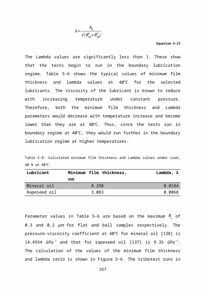
5. James, H. and S. Makiko, Regional climate change and national responsibilities. Environmental Research Letters, 2016. 11(3): p. 034009.
6. Heywood, John B. (1988), Internal Combustion Engine Fundamentals, McGraw-Hill Inc., New York, P. 730.
7. Tung, Simon C, & McMillan, Michael L. (2004). Automotive tribology overview of current advances and challenges for the future. Tribology International, 37(7), 517-536.
8. Johansson, S., et al., Experimental friction evaluation of cylinder liner/piston ring contact. Wear, 2011. 271(3–4): p. 625-633.
9. Schellnhuber, H.J., S. Rahmstorf, and R. Winkelmann, Why the right climate target was agreed in Paris. Nature Clim. Change, 2016. 6(7): p. 649-653.
10. Mackney D. et al. Automotive lubricants. In: Totten GE. and Tung SC. Eds. Automotive lubricants and testing. ASTM MNL 62. 2012. ASTMi. P.36.
11. Miller, A.L., et al., Role of Lubrication Oil in Particulate Emissions from a Hydrogen-Powered Internal Combustion Engine. Environmental Science & Technology, 2007. 41(19): p. 6828-6835.
12. Salimon, J., N. Salih, and E. Yousif, Biolubricants: Raw materials, chemical modifications and environmental benefits. European Journal of Lipid Science and Technology, 2010. 112(5): p. 519-530.
13. Arumugam, S. and G. Sriram, Synthesis and characterization of rapeseed oil bio-lubricant dispersed with nano copper oxide: Its effect on wear and frictional behavior of piston ring–cylinder liner combination. Proceedings of the Institution of Mechanical Engineers, Part J: Journal of Engineering Tribology, 2014. 228(11): p. 1308-1318.
14. Woydt, M., No/Low SAP and Alternative Engine Oil Development and Testing. 2007.
15. Mackney D. et al. Automotive lubricants. In: Totten GE. and Tung SC. Eds. Automotive lubricants and testing. ASTM MNL 62. 2012. ASTMi.
16. Aldana, P., et al., Action Mechanism of WS2 Nanoparticles with ZDDP Additive in Boundary Lubrication Regime. Tribology Letters, 2014. 56(2): p. 249-258.
17. Tomala, A., et al., Interaction Between Selected MoS2 Nanoparticles and ZDDP Tribofilms. Tribology Letters, 2015. 59(1): p. 1-18.
18. Martin, J.M. and N. Ohmae, eds. Nanolubricants. 2008, John Wiley & Sons Ltd.19. Wong, K.V. and O. De Leon, Applications of Nanofluids: Current and Future.
Advances in Mechanical Engineering, 2010. 2010.20. De-Xing Peng, Cheng-Hsien Chen, Yuan Kang, Yeon-Pun Chang, Shi-Yan Chang,
(2010) "Size effects of SiO2 nanoparticles as oil additives on tribology of lubricant", Industrial Lubrication and Tribology, Vol. 62 Iss: 2, pp.111 - 120.
21. Mansot, J., Bercion, Y., Romana, L., & Martin. (2009). Nanolubrication. Brazilian Journal of Physics, 39(1A), 186-197.
22. Stefanov, M. N., Enyashin, A., Seifert, G., & Heine, T. (2008). Nanolubrication: How do MoS 2 -based nanostructures lubricate? Journal of Physical Chemistry C, 112(46), 17764-17767.
23. Aldana, P. (2014). Action mechanism of WS2 nanoparticles with ZDDP additive in boundary lubrication regime. Tribology Letters, 56(2), 249-258.
24. Arumugam, S. and G. Sriram, Preliminary Study of Nano- and Microscale TiO2 Additives on Tribological Behavior of Chemically Modified Rapeseed Oil. Tribology Transactions, 2013. 56(5): p. 797-805.
167
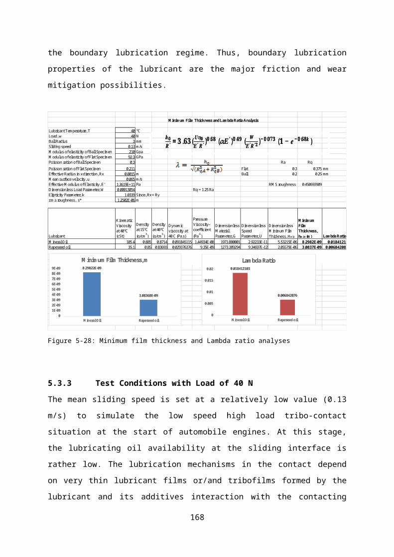
25. Gu, K., B. Chen, and Y. Chen, Preparation and tribological properties of lanthanum-doped TiO2 nanoparticles in rapeseed oil. Journal of Rare Earths, 2013. 31(6): p. 589-594.
26. Maliar, T., et al., Tribological behaviour of mineral and rapeseed oils containing iron particles. Industrial Lubrication and Tribology, 2015. 67(4): p. 308-314.
27. Reeves, C., et al., The Size Effect of Boron Nitride Particles on the Tribological Performance of Biolubricants for Energy Conservation and Sustainability. Tribology Letters, 2013. 51(3): p. 437-452.
28. Xu, Z., et al., Morphological Influence of Molybdenum Disulfide on the Tribological Properties of Rapeseed Oil. Tribology Letters, 2013. 49(3): p. 513-524.
29. Yan, J., et al., The tribological performance and tribochemical analysis of novel borate esters as lubricant additives in rapeseed oil. Tribology International, 2014. 71(0): p. 149-157.
30. Zhao, C., et al., The Tribological Properties of Zinc Borate Ultrafine Powder as a Lubricant Additive in Sunflower Oil. Tribology Transactions, 2014: p. 425-434.
31. Totten, George E, & Tung, Simon. (2012). Automotive lubricants and testing (Automotive lubricants and testing handbook Automotive lubricants and testing).
32. Williams, J. (2005). Engineering Tribology.33. Barnes, A.M., K.D. Bartle, and V.R.A. Thibon, A review of zinc
dialkyldithiophosphates (ZDDPS): characterisation and role in the lubricating oil. Tribology International, 2001. 34(6): p. 389-395.
34. Mackney D. et al. Automotive lubricants. In: Totten GE. and Tung SC. Eds. Automotive lubricants and testing. ASTM MNL 62. 2012. ASTM International
35. Stachowiak, G.W., Engineering tribology [electronic resource]. Fourth edition. ed, ed. A.W. Batchelor and A.W. Batchelor. 2014: Oxford : Elsevier/Butterworth-Heinemann, 2014.
36. Henderson, K.O. and may, C.J. Lubricant properties and characterisation. In: Automotive lubricants and testing. Eds: Totten, G.E. and S. Tung (2012) SAE and ASTM International
37. Biolubricants : science and technology, ed. J.C.J. Bart, E. Gucciardi, and S. Cavalloro. 2013, Cambridge, UK
Philadelphia, PA: Cambridge, UKPhiladelphia, PA : Woodhead Publishing, 2013.38. Engine Oil Viscosity Classification. 2009, SAE International.39. Pillon, L. Z. (2011). Surface activity of petroleum derived lubricants, CRC Press.
40. Gschwender, L J. et al. 2001. Liquid lubricants and lubrication. In: Modern Tribology Handbook. Ed: B Barat. CRC
41. Bart, J., Gucciardi, Emanuele, & Cavalloro, Stefano. (2013). Biolubricants : Science and technology (Woodhead Publishing series in energy, no. 46). Cambridge, UK ; Philadelphia, PA: Woodhead Publishing.
42. Totten, G.E. and S. Tung, Automotive Lubricants and Testing Automotive Lubricants and Testing, ed. G.E. Totten and S. Tung. 2012: SAE and ASTM International, 2012.
43. Quinchia, L.A., et al., Low-temperature flow behaviour of vegetable oil-based lubricants. Industrial Crops and Products, 2012. 37(1): p. 383-388.
168
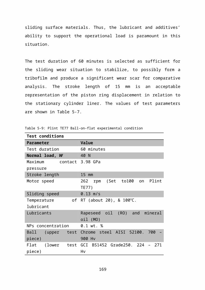
44. Crawford, J., A. Psaila and S.T. Orszulik (2010). Miscellaneous Additives and Vegetable Oils. In: Chemistry and Technology of Lubricants. Eds: R.M. Mortier, M.F. Fox and S.T. Orszulik. Springer Verlag (Online resource).
45. Salimon, J., N. Salih, and E. Yousif, Industrial development and applications of plant oils and their biobased oleochemicals. Arabian Journal of Chemistry, 2012. 5(2): p. 135-145.
46. Reeves, C.J., et al., The influence of fatty acids on tribological and thermal properties of natural oils as sustainable biolubricants. Tribology International, 2015. 90: p. 123-134.
47. Mackney, D. et al. (2012) "Automotive Lubricants". In Automotive Lubricants and Testing, Eds. G.E. Totten and S.C. Tung. ASTMi, West Conshohocken, PA.
48. Bovington, C.H. (2010). Friction, Wear and the Role of Additives in Controlling Them. In: Chemistry and Technology of Lubricants. Eds: R.M. Mortier, M.F. Fox and S.T. Orszulik. Springer Verlag (Online resource).
49. Spikes, H., The History and Mechanisms of ZDDP. Tribology Letters, 2004. 17(3): p. 469-489.
50. Mortier, R.M., M.F. Fox, and S.T. Orszulik, Chemistry and technology of lubricants. 2010: Springer Verlag.
51. Dienwiebel, M. and K. Pöhlmann, Nanoscale Evolution of Sliding Metal Surfaces During Running-in. Tribology Letters, 2007. 27(3): p. 255-260.
52. Stachowiak, G.W., Engineering tribology. Fourth edition. ed, ed. A.W. Batchelor and A.W. Batchelor. 2014: Oxford : Elsevier/Butterworth-Heinemann, 2014.
53. Ingole, S., et al., Tribological behavior of nano TiO2 as an additive in base oil. Wear, 2013. 301(1–2): p. 776-785.
54. Mackney, D. et al. (2012) "Automotive Lubricants". In Automotive Lubricants and Testing, Eds. G.E. Totten and S.C. Tung, ASTMi, West Conshohocken, PA.
55. Bart, Jan C.J., et al. Biolubricants Science and Technology. 2013, Woodhead Publishing. Chapt. 7. Pp. 351-395.
56. Batchelor, A.W. and G.W. Stachowiak, Engineering tribology. 2005: Butterworth Heinemann.
57. Prof. P. Jost. Fifth World Tribology Conference, Kyoto, Japan. September 2009.58. Bart, J. (2013). Biolubricants : Science and technology. Cambridge, UK ;
Philadelphia, PA: Woodhead Publishing.59. Kapoor, A. et al.(2001), Automotive Tribology, in Modern Tribology Handbook,
Bushan, B. (Ed.). Vol.2. CRC Press. Boca Raton. P. 1225.60. Mackney, D. et al. (2012) "Automotive Lubricants". In Automotive Lubricants and
Testing, Eds. G.E. Totten and S.C. Tung. ASTMi, West Conshohocken, PA. P. 23. 61. yamaguchi, E.S. et al. (2012). "Problems and Opportunities regarding the
Lubrication of Modern Automotive Engines" In Automotive Lubrication and Testing, Eds. G.E. Totten and S.C. Tung, ASTMi, West Conshohocken, PA. P. 200.
62. Hamrock, B. (1994). Fundamentals of fluid film lubrication (McGraw-Hill series in mechanical engineering). New York ; London: McGraw-Hill.
63. Gohar, R., & Rahnejat, Homer. (2008). Fundamentals of tribology. London: Imperial College Press.
64. Williams, J. (2005). Engineering Tribology.65. Sedlaček, M., B. Podgornik, and J. Vižintin, Influence of surface preparation on
roughness parameters, friction and wear. Wear, 2009. 266(3–4): p. 482-487.66. Mofidi, M., E. Kassfeldt, and B. Prakash, Tribological behaviour of an elastomer
aged in different oils. Tribology International, 2008. 41(9–10): p. 860-866.
169
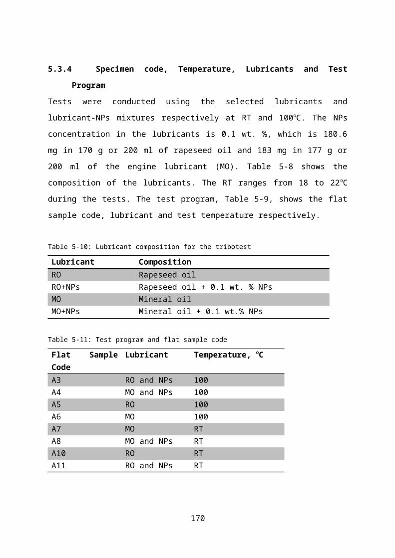
67. Pettersson, U. and S. Jacobson, Influence of surface texture on boundary lubricated sliding contacts. Tribology International, 2003. 36(11): p. 857-864.
68. Yamaguchi, K., et al., Effect of surface roughness on friction behaviour of steel under boundary lubrication. Proceedings of the Institution of Mechanical Engineers, Part J: Journal of Engineering Tribology, 2014.
69. Stachowiak, G.W., Experimental methods in tribology [electronic resource], ed. A.W. Batchelor, G.B. Stachowiak, and A.W. Batchelor. 2004, AmsterdamLondon: Amsterdam London : Elsevier, 2004.
70. Williams, J., Engineering Tribology. 2005: Cambridge : Cambridge University Press, 2005.
71. Hsu, S.M. and R.S. Gates, Boundary lubricating films: formation and lubrication mechanism. Tribology International, 2005. 38(3): p. 305-312.
72. Hsu, S.M., E.E. Klaus, and H.S. Cheng, A mechano-chemical descriptive model for wear under mixed lubrication conditions. Wear, 1988. 128(3): p. 307-323.
73. Fujita, H. and H.A. Spikes, The formation of zinc dithiophosphate antiwear films. Proceedings of the Institution of Mechanical Engineers, Part J: Journal of Engineering Tribology, 2004. 218(4): p. 265-278.
74. Axen, N, Hogmark, S, Jacobson, S. (2001). Friction and wear measurement techniques. Chapt. 13. Modern tribology handbook. CRC Press. London.
75. Stachowiak, G.W., A.W. Batchelor, and G.B. Stachowiak, Experimental Methods in Tribology: Tribology and Interface Engineering 44.
76. Bolander, N.W., et al., Lubrication regime transitions at the piston ring-cylinder liner interface. Proceedings of the Institution of Mechanical Engineers, Part J: Journal of Engineering Tribology, 2005. 219(1): p. 19-31.
77. Kato, K. and Adachi, K. (2001). Wear mechanisms. In: Modern tribology handbook, CRC Press, London.
78. https://tribos.wordpress.com/2016/10/27/systems-approach-to-wear-problems/
79. Bayer, R.G., Wear analysis for engineers. 2002, New York: New York : HNB Publishing, 2002.
80. Bowden, F., Moore, A., & Tabor, D. (1943). The Ploughing and Adhesion of Sliding Metals. Journal of Applied Physics., 14(2), 80.
81. Fouvry, S., et al., Palliatives in fretting: A dynamical approach. Tribology International, 2006. 39(10): p. 1005-1015.
82. Pearson, S.R., et al., The effect of temperature on wear and friction of a high strength steel in fretting. Wear, 2013. 303(1–2): p. 622-631.
83. Woydt, M. and R. Wäsche, The history of the Stribeck curve and ball bearing steels: The role of Adolf Martens. Wear, 2010. 268(11–12): p. 1542-1546.
84. Kalin, M., I. Velkavrh, and J. Vižintin, The Stribeck curve and lubrication design for non-fully wetted surfaces. Wear, 2009. 267(5–8): p. 1232-1240.
85. Hamrock, B. (1994). Fundamentals of fluid film lubrication (McGraw-Hill series in mechanical engineering). New York ; London: McGraw-Hill.
86. Hamrock, B., Schmid, Steven R, & Jacobson, Bo O. (2004). Fundamentals of fluid film lubrication (2nd ed., Mechanical engineering (Marcel Dekker, Inc.) ; 169). New York: Marcel Dekker.
87. Hsu SM, and Gates RS. Boundary lubrication and boundary lubricating films. CRC Handbook of modern tribology. Chapter 12, 2001.
170
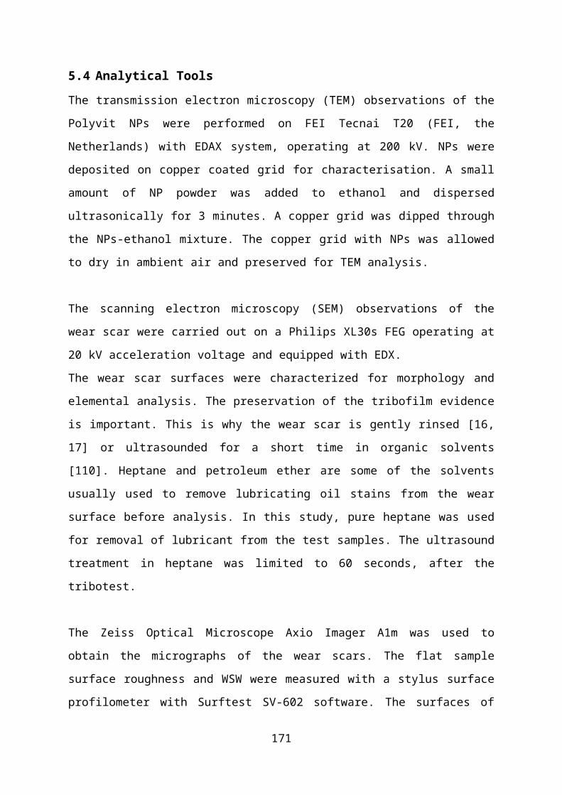
88. Kalin, M., J. Kogovšek, and M. Remškar, Nanoparticles as novel lubricating additives in a green, physically based lubrication technology for DLC coatings. Wear, 2013. 303(1–2): p. 480-485.
89. Morris, N., et al., Tribology of piston compression ring conjunction under transient thermal mixed regime of lubrication. Tribology International, 2013. 59(0): p. 248-258.
90. Ali, M.K.A., et al., Improving the tribological characteristics of piston ring assembly in automotive engines using Al2O3 and TiO2 nanomaterials as nano-lubricant additives. Tribology International, 2016. 103: p. 540-554.
91. Dan, G., X. Guoxin, and L. Jianbin, Mechanical properties of nanoparticles: basics and applications. Journal of Physics D: Applied Physics, 2014. 47(1): p. 013001.
92. Reeves, C.J., et al., The influence of surface roughness and particulate size on the tribological performance of bio-based multi-functional hybrid lubricants. Tribology International, 2015. 88: p. 40-55.
93. Dai, W., et al., Roles of nanoparticles in oil lubrication. Tribology International, 2016. 102: p. 88-98.
94. Lee, K., et al., Understanding the Role of Nanoparticles in Nano-oil Lubrication. Tribology Letters, 2009. 35(2): p. 127-131.
95. Hernández Battez, A., et al., Friction reduction properties of a CuO nanolubricant used as lubricant for a NiCrBSi coating. Wear, 2010. 268(1–2): p. 325-328.
96. Callister, W., & Rethwisch, David G. (2007). Materials science and engineering : An introduction (7th ed. / with special contributions by David G. Rethwisch. ed.). New York: John Wiley.
97. Kato, H. and K. Komai, Tribofilm formation and mild wear by tribo-sintering of nanometer-sized oxide particles on rubbing steel surfaces. Wear, 2007. 262(1–2): p. 36-41.
98. Luo, T., et al., Tribological properties of Al2O3 nanoparticles as lubricating oil additives. Ceramics International, 2014. 40(5): p. 7143-7149.
99. Varrla Eswaraiah, Venkataraman Sankaranarayanan, and Sundara Ramaprabhu, (2011) “Graphene-Based Engine Oil Nanofluids for Tribological Applications”, ACS Applied Materials & Interfaces, Vol. 3, Pp. 4221–4227.
100. Jiao, D., et al., The tribology properties of alumina/silica composite nanoparticles as lubricant additives. Applied Surface Science, 2011. 257(13): p. 5720-5725.
101. Aldana, P.U., et al., WS2 nanoparticles anti-wear and friction reducing properties on rough surfaces in the presence of ZDDP additive. Tribology International, 2016. 102: p. 213-221.
102. Kogovšek, J., et al., Influence of surface roughness and running-in on the lubrication of steel surfaces with oil containing MoS2 nanotubes in all lubrication regimes. Tribology International, 2013. 61: p. 40-47.
103. Sadhik Basha, J., "An Experimental Analysis of a Diesel Engine Using Alumina Nanoparticles Blended Diesel Fuel," SAE Technical Paper 2014-01-1391, 2014, doi:10.4271/2014-01-1391.
104. Lin, J., L. Wang, and G. Chen, Modification of Graphene Platelets and their Tribological Properties as a Lubricant Additive. Tribology Letters, 2011. 41(1): p. 209-215.
105. Gara, L. and Q. Zou, Friction and Wear Characteristics of Oil-Based ZnO Nanofluids. Tribology Transactions, 2013. 56(2): p. 236-244.
106. Gulzar, M., et al., Tribological performance of nanoparticles as lubricating oil additives. Journal of Nanoparticle Research, 2016. 18(8): p. 223.
171
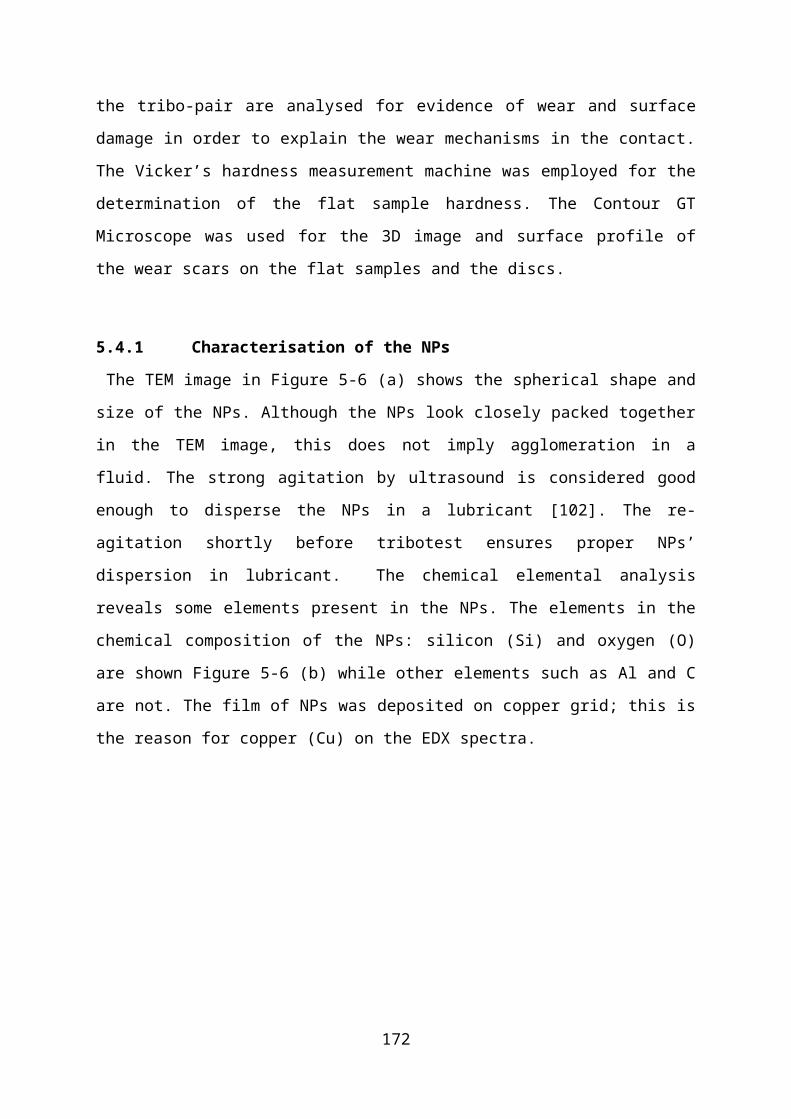
107. Peng, D.X., et al., Size effects of SiO2 nanoparticles as oil additives on tribology of lubricant. Industrial Lubrication and Tribology, 2010. 62(2): p. 111-120.
108. Demas, N., et al., Tribological Effects of BN and MoS2 Nanoparticles Added to Polyalphaolefin Oil in Piston Skirt/Cylinder Liner Tests. Tribology Letters, 2012. 47(1): p. 91-102.
109. Joly-Pottuz, L., et al., Ultralow-friction and wear properties of IF-WS2 under boundary lubrication. Tribology Letters, 2005. 18(4): p. 477-485.
110. Kalin, M., J. Kogovšek, and M. Remškar, Mechanisms and improvements in the friction and wear behavior using MoS2 nanotubes as potential oil additives. Wear, 2012. 280–281: p. 36-45.
111. Rosentsveig, R., et al., Fullerene-like MoS2 Nanoparticles and Their Tribological Behavior. Tribology Letters, 2009. 36(2): p. 175-182.
112. Sui, T., et al., Effect of particle size and ligand on the tribological properties of amino functionalized hairy silica nanoparticles as an additive to polyalphaolefin. J. Nanomaterials, 2015. 16(1): p. 427-427.
113. Yadgarov, L., et al., Tribological studies of rhenium doped fullerene-like MoS2 nanoparticles in boundary, mixed and elasto-hydrodynamic lubrication conditions. Wear, 2013. 297(1–2): p. 1103-1110.
114. Zhang, M., et al., Performance and anti-wear mechanism of CaCO3 nanoparticles as a green additive in poly-alpha-olefin. Tribology International, 2009. 42(7): p. 1029-1039.
115. Agarwal, D.K., A. Vaidyanathan, and S. Sunil Kumar, Synthesis and characterization of kerosene–alumina nanofluids. Applied Thermal Engineering, 2013. 60(1–2): p. 275-284.
116. Huang, H.D., et al., An investigation on tribological properties of graphite nanosheets as oil additive. Wear, 2006. 261(2): p. 140-144.
117. Kedzierski, M.A., Viscosity and density of aluminum oxide nanolubricant. International Journal of Refrigeration, 2013. 36(4): p. 1333-1340.
118. Lee, C.-G., et al., A study on the tribological characteristics of graphite nano lubricants. International Journal of Precision Engineering and Manufacturing, 2009. 10(1): p. 85-90.
119. Mohan, N., et al., Tribological Properties of Automotive Lubricant SAE 20W-40 Containing Nano-Al2O3 particles. 2014, SAE International.
120. Peña-Parás, L., et al., Effect of CuO and Al2O3 nanoparticle additives on the tribological behavior of fully formulated oils. Wear, 2015. 332–333: p. 1256-1261.
121. Thakre, A.A. and A. Thakur, Study of behaviour of aluminium oxide nanoparticles suspended in SAE20W40 oil under extreme pressure lubrication. Industrial Lubrication and Tribology, 2015. 67(4): p. 328-335.
122. Mahbubul, I.M., et al., Effect of Ultrasonication Duration on Colloidal Structure and Viscosity of Alumina–Water Nanofluid. Industrial & Engineering Chemistry Research, 2014. 53(16): p. 6677-6684.
123. López, T.D.-F., et al., Engineered silica nanoparticles as additives in lubricant oils. Science and Technology of Advanced Materials, 2015. 16(5): p. 055005.
124. Peng, D.X., et al., Tribological properties of diamond and SiO2 nanoparticles added in paraffin. Tribology International, 2009. 42(6): p. 911-917.
125. Sia, S. and A.D. Sarhan, Morphology investigation of worn bearing surfaces using SiO2 nanolubrication system. The International Journal of Advanced Manufacturing Technology, 2014. 70(5-8): p. 1063-1071.
172
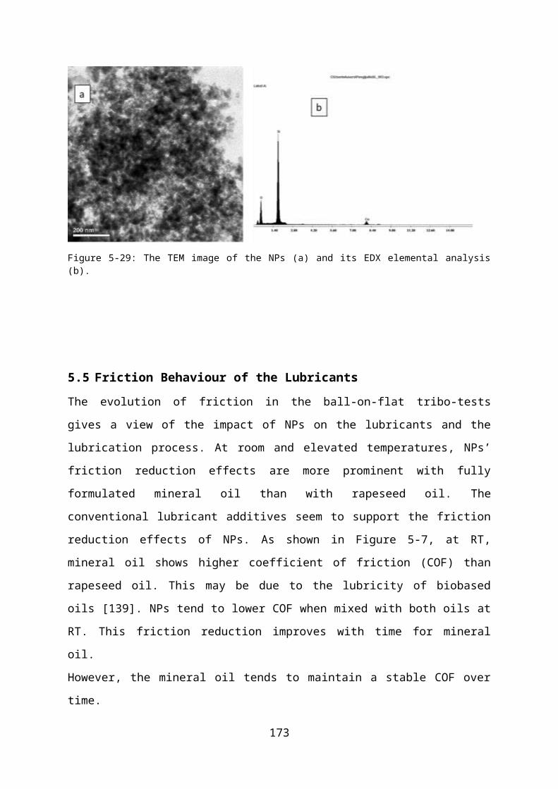
126. Sia, S.Y., E. Bassyony, and A.D. Sarhan, Development of SiO2 nanolubrication system to be used in sliding bearings. The International Journal of Advanced Manufacturing Technology, 2014. 71(5-8): p. 1277-1284.
127. Sui, T., et al., Bifunctional hairy silica nanoparticles as high-performance additives for lubricant. Scientific Reports, 2016. 6: p. 22696.
128. Teresa Díaz-Faes, L., et al., Engineered silica nanoparticles as additives in lubricant oils. Science and Technology of Advanced Materials, 2015. 16(5): p. 055005.
129. Yue, W., et al., Study of the Regenerated Layer on the Worn Surface of a Cylinder Liner Lubricated by a Novel Silicate Additive in Lubricating Oil. Tribology Transactions, 2010. 53(2): p. 288-295.
130. Su, Y., L. Gong, and D. Chen, An investigation on tribological properties and lubrication mechanism of graphite nanoparticles as vegetable based oil additive. J. Nanomaterials, 2015. 16(1): p. 203-203.
131. Singh, V.K., et al., Lubricating properties of silica/graphene oxide composite powders. Carbon, 2014. 79(0): p. 227-235.
132. ASTM International, ASTM G133-05(2010), Standard test method for linearly reciprocating ball-on-flat sliding wear.
133. Balachandran, G., et al., Mechanical and wear behavior of alloyed gray cast iron in the quenched and tempered and austempered conditions. Materials & Design, 2011. 32(7): p. 4042-4049.
134. Arumugam, S., G. Sriram, and R. Ellappan, Bio-lubricant-biodiesel combination of rapeseed oil: An experimental investigation on engine oil tribology, performance, and emissions of variable compression engine. Energy, 2014. 72(0): p. 618-627.
135. Gryglewicz, S., M. Muszyński, and J. Nowicki, Enzymatic synthesis of rapeseed oil-based lubricants. Industrial Crops and Products, 2013. 45(0): p. 25-29.
136. Stachowiak, G., & Batchelor, A. W. (2014). Engineering tribology (4th ed.).137. Biresaw, G. and G. Bantchev, Pressure Viscosity Coefficient of Vegetable Oils.
Tribology Letters, 2013. 49(3): p. 501-512.138. Khonsari, M., & Booser, E. Richard. (2007). Applied tribology : Bearing design and
lubrication. (2nd ed. / Michael M. Khonsari and Earl Richard Booser. ed.). Chichester: John Wiley.
139. Rudnick, L.R., ed. Synthetics, Mineral Oils, and Bio-Based Lubricants: Chemistry and Technology, Second Edition. 2013, CRC Press Inc.
140. Alves, S.M., et al., Tribological behavior of vegetable oil-based lubricants with nanoparticles of oxides in boundary lubrication conditions. Tribology International, 2013. 65(0): p. 28-36.
141. Bhushan, B. (2001). Modern tribology handbook. Boca Raton, Fla. ; London: CRC Press.
142. Tomala, A., et al., Interactions between MoS2 nanotubes and conventional additives in model oils. Tribology International, 2017. 110: p. 140-150.
143. Keller, J., et al., Influence of chemical composition and microstructure of gray cast iron on wear of heavy duty diesel engines cylinder liners. Wear, 2007. 263(7–12): p. 1158-1164.
144. Desai Gowda, H., Mukunda, S., & Herbert, P. (2014). Correlation of Tribological Properties with Microstructure and Mechanical Properties of Graphite Cast Irons Centrifugally Cast for Engine Liner. Transactions of the Indian Institute of Metals, 67(5), 731-740.
173
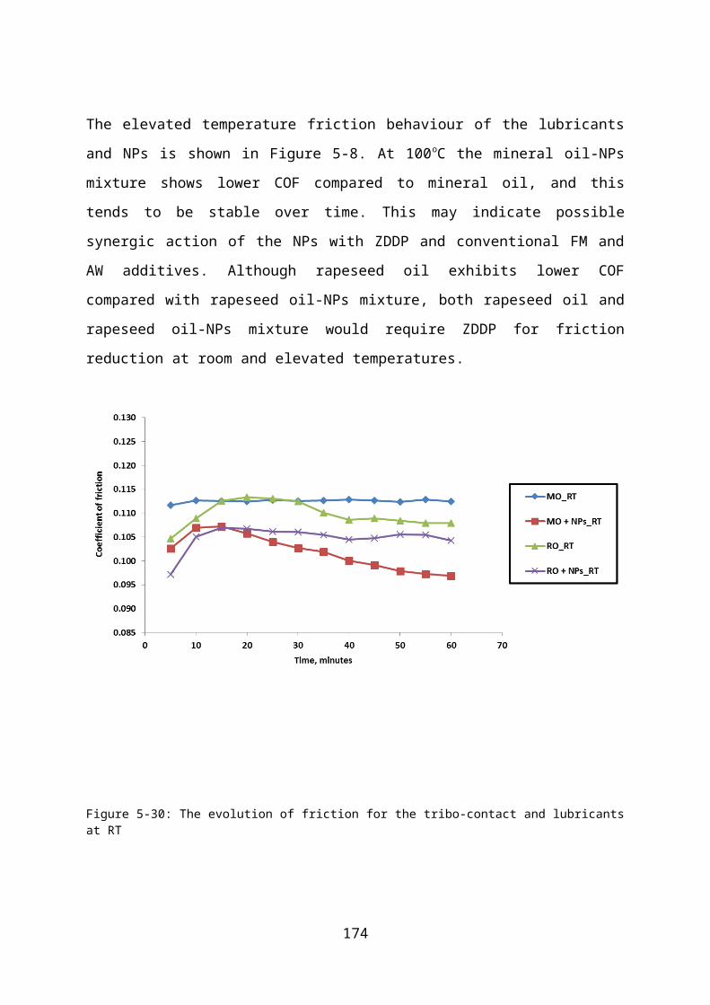
145. Collini, Nicoletto, & Konečná. (2008). Microstructure and mechanical properties of pearlitic gray cast iron. Materials Science & Engineering A, 488(1), 529-539.
174