Embed Size (px)
Citation preview

Materiel Test Procedure 2-4-0' ,"•12 May 1969 Yuma Proving Ground /
U.S. ARMY TEST AND EVALUATION COMMAND o i/ -ENVIRONMENTAL TEST PROCEDURE -
DESERT ENVIRONMENTAL TESTINg OF WHEELED AND TRACKED VEHICS
I 1I. OBJECTIVE
The purpose of this Materiel Test Procedure is to determine theoperating, maintenance, and durability characteristics of wheeled andtracked vehicles when operating in various types of desert terrain.,,
S 2. BACKGROUND
Each major item conceived and developed, and produced for the Armymust be capable of performing under various envi-onments of the world includingthe varying desert conditions (hot-dry during daytime and temperature dropsat nighttime), which may have a significant effect on the performance character-istics of the test item. Many items of materiel do not meet the criteria foradequate performance in the desert environment. These criteria are concernedwith operating, maintenance, durability and reliability characteristics of thetest item and the effects of desert environmental conditions on the physicalcharacteristics of the test item.
3. REQUIRED EQUIPMENT
a. Combat equipment and supplies for combat vehicles.b. Photographic facilities including cameras and film.c. High density payloads (actual or simulated) for transport vehicles.d. Test vehicles maintenance package and Technical Manuals.e. Maintenance facilities as required.f. Applicable laboratory facilities as required.g. Calibrated engine tachometer and recording equipment.h. Calibrated fuel pressuire gage.i. Thermocouples, pressure gages and recording equipment as required.J. Knock sensing instrumentation as required for pressure sensing
and vibration sensing.k. Oscilloscope and oscilloscope camera and film.1. Specification fuels of known octane rating as follows:
a) Combat gasoline MIL-G-3056, Type 1, Ref N.b) Referee grade gasoline MIL-G-46015, Grade 1, Ref AD.c) Automotive gasoline Federal Spec, VV-G-76, Class A, Ref D.
m. Primary reference fuels (iso-octane and n-heptane) in steps of
2.5 octane ratings between 60 and 100 octane.n. Severity reference fuels (iso-octane, n-heptane, and di-isobutylene)
in st,.ps of 2.5 octane (research method) between 75 and 100 octane.o. A series of full-boiling-range reference fuels in steps of one
or two octane numbers (research method) between 86 and 105 octane prepared Iromntest gasoline established as standards by Coordinatinrg Research Council Inc.,(CRC).
(CRC) To 70 RoProducoe bvNATIONAL TECHNICALS'INFORMATION SERVICE
.. , , .-. $ -10- Vad, 22151

4TP 2-4-00112 May 1969 )
p. Power-absorption trailer or dynamometcr for controlling load andspeed of test vehicle.
q. Specific road courses as described in each test.r. A flow-tested carburetor if available.s. Soak shelters as required,t. Fuel blending facilities capable of sturing, cooling, blending,
and analyzing specification fuels and high and low vapor fuel samples.
NOTE: The above facilities normally provided by the chemicalunit of the test support branch should have analyticalcapabilities to determine fuel Reid vapor pressure (RVP),distillation curves, and vapor-liquid (V/L) ratio atspecific temperatures.
u. Fuel sampling equipment, incliding sample containers, siphonapparatus for collecting samples by water displacement, and means ofrefrigerating samples and bottles.
v. Means of transporting fuels and fuel samples (55 gallon drums,etc.)
w. Meteorological station capable of obtainiing
a) Temperatureb) Windspeed and directionc) Relative humidityd) Barometric pressuree) Solar radiation
x. Referee grades of lubricants as required.y. Vehicle similar to vehicle under test (pilot vehicle).z. Personnel dust protection equipment, such as dust masks and
goggles.aa. Facilities and equipment for collecting, drying, weighing, and
measuring dust eccumulations and samples.ab. Instrumentation, such as a piezoelectric transducer sensor, to
measure air flow restriction across the air cleaner, when required.
4. REFERENCES
A. MTP 9-4-001, Desert Environmental Test of Construction, Support,and Service Equipment.
B. MTP 10-4-001, Desert Environmental Test of General Supplies andEquipment
C. USATECOM Pamphlet 700-700, USATECOM Materiel Test ProceduresD. MTP 2-2-500, Vehicle CharacteristicsE. MTP 2-2-501, Amphibious Vehicle CharacteristicsF. MTP 2-2-502, Inspections (Automotive)G. MTP 2-2-505, Preliminary OperationH. MTP 2-2-508, Safety Evaluation (Automotive)
-2-

MTP 2-4-001
12 May 1969.'/
I. A•C Regulation 385-12, Verification of Safety of Materielfrom Development through Testing and Supply to Disposition.
J. AR 705-15, Operation of Materiel under Extreme Conditionsof Environment.
K. MTP 2-2-503, Maintenance.L. MIP 2-2-701, Fuels and Lubricants.M. Aberdeen Proving Ground Standard Procedure for the Automotive
Engineering Laboratory Division, Procedures for Determiningt Lhe Octane Requirement of Military Engines.
N. Military Specification MIL-G-3056, Gasoline, Automotive, Combat0. Federal Specification VV-G-76, Gasoline, AutomotiveP. MTP 2-2-603, Vehicle Fuel Consumption.
Q. MTP 2-2-607, Engine and Power Train Cooling Systems (Vehicle)R. MTP 2-2-608, Braking.S. MTP 2-2-604, Drawbar Pull.T. Military Specification MIL-A-62048, Air Cleaners, Automotive:
Heavy-Duty, Dry-Type (for Internal-Combustion Engines).U. MTP 2-2-704, Tires.V. MTP 2-2-619, Off-Road Vehicle Mobility TestW. MTP 2-2-506, Durability Testing of Wheeled Vehicles
X. MTP 2-2-507, Durability Testing of Tracked VehiclesY. Test Capabilities at Yuma Proving Ground, Yuma Proving Ground,
USATECOM, AD no. 824116.Z. MTP 2-2-615, Security from Detection (Vehicles).
AA. MTP 2-2-803, Human Factors Engineering (Vehicles).AB. MTP 2-2-508, Safety Evaluation (Automotive).AC. Technical Report EP-53, A Study of Desert Surface Conditions,
Quartermaster Research and Development Center, Natick,Massachusetts.
AD. Military Specification MIL-G-46015, Gasoline, Automotive,Combat, Referee Grade
AE. Brooks, Wahner E., Discussion of Desert Terrain: U. S. ArmyYuma Proving Ground Technical Memorandum RO-I-67, May 1967,p. 2-5.
AF. Ramaley, Francis, MSS, World Deserts: Limits and EnvironmentalCharacteristics, Draft of Special Report No. 57, EnvironmentalProtection Branch, Office of the Quartermaster General, 15April 1952.
SAG. Bradehl, A. R., and E. P. Kiefer, A Classification System for. --- Unprepared Landing Areas, Planning Research Corp., Los Angeles,
California, PRC-R-42, January 1956 (AD No. 115-606). Van Lopik, J. R., and C. R. Kolb, Handbook, A technique for
Preparing Desert Terrain Analogs, Technical Report No. 3-506,tC U. S. Army Engineer Waterways Experiment Station, Vicksburg,SMiss., May 1959. The coding, explained in detail in "Handbook".
Ai. Monkhouse, F. J., Principles of Physical Geography., 5th Ed.,Univ. of London Press., LTD., London EC21; U.K. 1962, pp. 2 28- 2 2 9 .
MT lIL Wd/GrIPOKNM
-3-

nrp 7-4-00112 May 1969 4:
AJ. Clements, Thomas D., and others; A Study of Desert SurfaceConditions: U. S. Army Quartermasters Research and EngineeringConmand, Technical Report EP-53, April 1957, pp 99-102
AK. Kesseli, J.E. and C. 3. Beaty, Desert Flood Conditions in theWhite Mountains of California and ;evada;. U. S. Army QuartermasterResearch and Engineering Command, Technical Report EP-108, p 5-13
AL. Frost, Robert E., and others; Terrain Study of the Yuma TestStation Area. Arizona: Purdue University Engineering Experiment
Station, LaFayette, Indiana, March 1955 (AD No. 626-500), p 47-48;72-84.
AM. Clements, op. cit., p. 91-95AN. Frost, op, cit. p. 49-50; 85-93AO. Flissenbach, Erick, 1. "Relation of Surface Angle Distribution
to Particle Size Distribution on Alluvial Fans (Ariz)". Jour. Sed.Petrology, v. 22, No. 1, p. 25-28, March 1952. 2. "Geoloy. ofAlluvial Fans in Semi-arid Regions": Geol. Soc. America Bull,v. 65, No. 2, p. 175-189, February 1954
AP. Bull, William B., 1. Geomorphology of Alluvial Fans in FresnoCounty, California, U. S. Geol. Survey Prof, Paper 352-E, 1964.2. Alluvial Fans and Near-Surface Subsidence in Western FresnoCounty. California; U. S. Geol. Survey Prof. Paper 437-A, 1964.
AQ. Kesseli, op. cit. pa. 8-10AR. Schuman, S. A. and R. F. Hadley, "Arroyos and the Semi-Arid CyvEle
of Erosion, AM. Jour. Sci., v. 255, p. 161-174, 1957.AS. Blackwelder, Elict, "Desert Plains"; Jour. Geology, v. 39;
1931, p. 133-140AT. Clements, op, cit., p. 14-57AU. BLgnold, R. A., The Physics of Blown Sand and Desert Dunes,
Methren and Co., Ltd., London, E.C. 4, u. k., 2nd Ed., 1954
AV. Kolb, C.R., and W.K. Dornbusch, Jr., I. Analogs of Yuima Terrain
in the Middle East Desert (2 Vol), U. S. Army Engineer Waterways
Experiment Station, Vicksburg, Miss., Tech Report No. 3-630,Rpt No. 4 (Ad No. 487475, 6), June 1966. 2. Analogs of Yuma
Terrain in the Northweat African Desert (2 VOL), U. S. Army
Engineer Waterways Experiment Station, Vicksburg. Miss.,
Technical Report No. 3-630, Report No. 6, June 1965
AW. Ibid. Other reports in the U. S. Army Engineer Waterways Experi-
ment Station, Technical Report No. 3-360 Series include ReportNo. 1, Analogs of Yuma Terrair in the Northeast African D, _ert,
March 1959: Report No. 3, The Mexican Desert, April 1959; and
Report No. 5, ... the Southwest United States Desert, June 1964
5. SCOPE
5.1 SUMMARY
This WTP describes the foloving tý'sts to be performed on wheeled
and tracked vehicles daring desert environmental tests',
-4-

!IMTP 2-4-00112 May 1969
a. Performance Tests - A study to determine how the vehicleperforms under desert ewiromnental conditions consisting of the following:
1) Octane Requirements Tests - An evaluation of the miuimumoctane rating the test vehicles gasoline can be without
causing knock.2) Fuel Vapor Handling Capability - An evaluation of the test
vehicles resistance to vapor locking and other types ofpoor engiae performance associated with preirature vapor-
ization of fuel in the fuel system. "
3) Compatibility with Specification Grades of Fuels andLubricants - An evaluation of the effect of deserýenvironmental conditions on the test vehicle specified fuelslubricants, hydraulic fluids and related materials.
4) Fuel Consumption Tests - An evaluation of vehicle fuelconsumption under desert environmental conditions.
5) Engine Cooling System Tests - An evaluation of coolingcapabilities of the vehicle engine desert environmentalconditions.
6) Braking Adequacy - An evaluation of the braking capabilitiesof the vehicle under desert environmental conditions.
7) Drawbar Pull Tests - A test to determine the tractive effortof the vehicle under desert environmental conditions.
8) Air Cleaner Adequacy Tests - A test to determine the adequacyof the air cleaner to remove damaging dustparticle,, fromcombustion air of the vehicle engine,
b. Mobility Tests - A study to determine the effects of desertterrain upon the test vehicles mobility consisting of the following:
1) Sadu Mobility Tests - A test to determine sand traversingcapabilicy of the test vehicle.
2) Desert Cross - Country Mobility Tests - A test to determinethe vehicles ability to traverse the various types of desertterrain for a specified number of miles.
3) Durability Test - A test to determine the vehicle abilityto traverse all types of terrain and road conditions fora specified number of miles.
c. Exposure and Storage Tests - A test to determine the deteriorationeffects of the desert onvironment on the test vehicle.
d. Maintenance Tests - A test to determine the maintenance require-ments of the test vehicle under desert environmental conditions.
e. Security from Detection - A test to determine the test vehiclessusceptibility to detection under conditions encountered in various parts ofthe desert.
f. Human Engineering - A test to determine the compatibility of manand the vehicle under desert conditions.
g. Safety - A test to determine if the desert envirornental conditionshave any effects on vehicle safety.
-5-

'{P 2-4-uGi
12 -,ay t9b9
5.2 1 M1ATIOITIS
"T�i *rc 'tdur,! is limited ro the field testing under desertenvirof•rlzn.al corditiorts, of wheeled and tracked vehicles except those items,intended for ehelterece eL-vironments, warehouse lift trucks, construction and
rail equipstent.
These procedures are not intended to test velicle components such
as collective protection systems and tank stabilization systems which aretested in other Desert Envirowrer-tal Materiel Test Procedures.
6. PROCEDURLS
6.1 PREPARATION FOR TEST
6.1.1 Initial Inspection
3. Visually it.spect the test items upon receipt at the test site
in accordance with WfP 2-2-502.b. Repair or replace paits to remedy all significant deficiencies
found and record such deficiencies.c. Photograph all deficiencies.
6.1.2 Preliminary Operation
All test vehicles which have aot been operated previously shall be
subjected tc the procedures described in MTP 2-2-505.
6.1.3 Vethicle Mechanical Inspection Tests
Subject the test vehicle to the initial inspection procedures
as descritbea in MTP 2-2-502 ensuring that lubricants which are appropriatefor operation in the desert hot-dry environment replace the vehicles existinglubricauts.
b.l.4 Vehicle Characteristics
a. Prior to test determine the vehicle characteristics in accordance
with MTP 2-2-500.b. Compare each test item with all previously published descriptions
and record any differences.
6,1.5 Testing
The project engineer shall schedule the tests required by the
approved test plan so that as many types of data will be recorded onc time
as can be obtained with the personnel, facilities, and equipment available
and without interference with the objectives of the test.
-6-

II mTP •-4-001
12 May 1969
6.1.6 Safety
The project engineer shall ensure the following:
a. Reasonable protection for test personnel against sunstroke,heat exhaustion, and sunburn.
b. Indoctrination of test personnel on local hazards and suggestedprecautions by local safety personnel.
6.1.7 Operating Mode
The project engineer shall ensure the following:
a. That all test procedures are performed with the test itemoperated in the normal operating mode.
b. Discourage all efforts to abbreviate prescribed operations orto discard inconvenient combat supplies, payload, or vehicle equipment.
b.1.8 Maintenance
The project engineer shall ensure that the test item's maintenancepackage and sufficient quantities of the prescribed maintenance supplies areavailable at thc test site to enable testing to proceed.
"j 6.1.9 Performance Tests
6.1.9.1 Octane Requirements
Ensure that the following hab b :en accomplished Drier to conductingthe octane requirements tests
a. The test vehicle .nd engine have been proven to be in goodmezhanical condition.
b. The test vehicle engine has accumulated combustion chamber depositsduring a minimum of 30 hours of operation.
c. Ignition timing is set at the level specified by the manufacturerfor all spee( between maximum-torque and governed speed.
d. The governor has beer rendered inoperative at the governeespeed to allow for antiknock tests at the governed speeds.
e. A flow tested carburetor which meets the nanufacturers specifi-F cations has beer, installed.
NOTE: If a flow-tested carburetor is not available, the air fuel
ratios of the installed cari-aretor shall be choceled at thelow speed and high speed end& of the speed rang=,
f. The follcwing instrumentation shall be installed prior to test:
-7-

>ITP 2-4-00112 May 1969
I) A calibrated tachometer to measure engine speed.2) A fuel pressure gage at the caLaretor fuel inlet at
approximately the same level as the fuel line connection.3) Thermocouples to measure and record the following temperatures:
a) for anair-cooled engine:
(1) Carburetor inlet air.M2) All spark plug gaskets.(3) Two positions in the cooling air stream ahead of
each bank of cylinders.(4) Engine oil sump.
b) For a liquid cooled engine:
(1) Carburetor inlet air(2) Oil sump(3) Coolant leaving the engine
4) Detonation sensors, when required, to measure engine knock.
NOTE: Engine knock may be detected by pressure or vibration sensinginstruments.
g. Pressure-sensing instruments (piezoelectric transducers) mountedon modified ýpark plugs are the preferred form of sensor. The sudden increase A'.
of combustion chamber pressure which characterizes engine knock can usuallybe distinguished from the gradual incrEase of pressure which characterizesnormal combustion.
h. Sperry magnetostriction detonation sensors, or equivalentvibration detection devices, are sometimes used for knock detection, particu-larly on ar-couled engines. The greater rigidity and mass of liquid-cooledengines usually limit the usefulness of these sensors with such engines.
1) For pressure-type sensors: spark plugs modified for themounting of piezoelectric transducers.
2) For vibration-type sensors:
a) For air-cooled engines: mounted on each cylinderperpendicular to the top of the piston and as faras possible from the spark plugs.
b) For liquid-cooled engines: mounted along the cyliiderheads perpendicuiar to the tops of the piston and zsfar as possible from the spark plugs.
NOT: The exact number of sensors will depend on the length ofthe cylinder head, but generally one pickup will be installedfor each +wo cylinders.
I MTP 2-4-001
2 12 M-) 1969
-i. Install an auxiliary fuel system to introduce test fuels from5-gallon containers. The vehicle fuel tank su-,ply shall be disconnectedduring the octane requirements tests.
NOTE: 1. The auxiliary system shall be planned with care toavoid changing fuel transfer pressures.
2. Fuel systems using fuel injection pumps shall be modifiedto reroute bypass fuel so as to prevent mixing of testfuels.
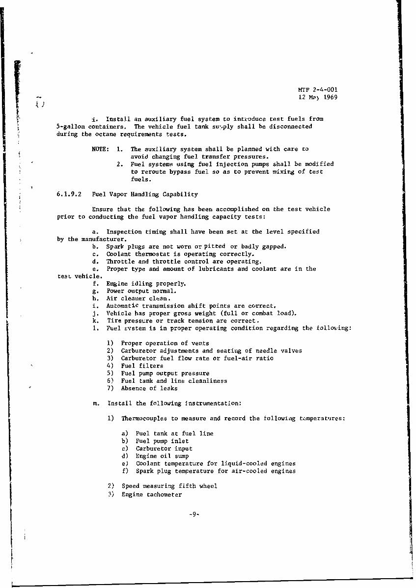
6.1.9.2 Fuel Vapor Handling Capability
S~Ensure that the following has been accomplished on the test vehicle
prior to conducting the fuel vapor handling capacity tests:
a. Inspection timing shall have been set at the level specifiedby the manufacturer.
b. Spark plugs are not worn or pitted or badly gapped.c. Coolant thermostat is operating correctly.d. Throttle and throttle control are operating.e. Proper type and amount of lubricants and coolant are in the
teSL vehicle.f. Engine idling properly.g. Power output normal.h. Air cleaner clean.
i. Automatic transmission shift points are correct,j. Vehicle has proper gross weight (full or combat load).k. Tire pressure or track tension are correct.1. Fuel Evstem is in proper operating condition regarding the follouing:
1) Proper operation of vents2) Carburetor adjustments and seating of needle valves3) Carburetor fuel flow rate or fuel-air ratio4) Fuel filters5) Fuel pump output pressure6) Fuel tank and line cleanliness7) Absence of leaks
m. Install the following instrumentation:
1) Thermocouples to measure and record the following tcmperatures:
a) Fuel tank at fuel lineb) Fuel pump inletc) Carburetor input
d) Engine oil sumpe) Coolant temperature for liquid-cooled enginesf) Spark plug temperature for air-cooled engines
2) Speed measuring fifth wheel
3) Engine tachometer
-9-
I

MTP 2-4-00112 May 1969
t.
4) Suitable timing devices5) Oscillograph for acceleration data6) Transducers to measure and record the fellowing pressures:
a) Fuel pressure in the fuel tank at the fuel lineb) Fuel pressure at the carburetor inlet
n. Record the ollowing meteorological data during tests:
1) Ambient temperature2) Relative humidity3) Barometric pressure (absolute)4) Wind speed and direction5) Solar radiation
0. Prior to test determine the test vehicles fuel vapor handlingcapacity using the following procedures.
NOTE: In those instances where the test vehicle's designed temperaturefor a given Reid vapor pressure (Rvp) is not available duriz~gtesting, use the equivalent Rvp, for the test items's criticalvapor-liquid ratio, as determined from Figure las follows:
1) Assume a test vehicle is designed to operate at ambienttemperatures up to 125*F on a fuel produced under aspecification allowing a maximum volatility of 9-psi-Rvp.
2) Assume also that the ambient temperature forecast for thedesert field test of vapor handling capacity is 110*F,cr 150 F less than the design maximum temperature.
3) As.ume that the critical vapor-liquid ratio limiting theperformance of most vehicles is about 20:1 (or V/L = 20).
4) Assume that the fuel system temperatures will vary onedegree for each degree of change of ambient temperature.
5) In Figure 1, locate the temperature at which a 9-psi-Rvpfuel wiUl show a vapor-liquid ratio of 20, i.e., at 1360 F.Subtrct 15' from that temperature, and find the point on theV/L = 20 curve which corresponds to the lower temperature(121"F).
6) From Figure 1, a blend which will have a volatility comparableto the specification fuels st 15*F cooler temperaturesmust have a V/L = 20 temperature of 121*F and an Rvp ofapproximately 11 psi.
6.1.9.3 Compatibility with Specification Grades of Fuels and Lubricants
Preparation for test shall be performed as described iiL iMrP 2-2-701.
6.1.9.4 Fuel Consumption
Preparation for test shall be performed as described in MTP 2-2-603.
-10-

MTP 2-4-00112 May 1969
14
13
12
CO 1 0 10 10 10I4 5 6 7
FaRr11 It
-II-p
9
7
6
100 110 120 130 140 150 160 170
FUEL TEMPERATURE (DEG F)
Figure 1. Relationships of Reid Vapor Pressure (Rvp) to Vapor-LiquidRatio (V/L) and Temperature for a Typical Series of Test FutelBlends
-11-

MP 2-4-00112 May 1969
6.1.9.5 Cooling
Preparation for test shall be performed as described in HTP 2-2-607.
6.1.9.6 Braking
Preparation for test shall be performed as described in MTP 2-2-608.
6.1.9.7 Drawbar Pull
Preparation for test shall be performed as described in MTP 2-2-604.
6.1.9.8 Air Cleaner Adequacy
Ensure that the following has been performed prior to conductingair cleaner adequacy tests.
a. Verify that all interior surfaces of the test item, and thefilter element, are clean. If the filter element is of the replaceable type,install a new element.
b. Install and calibrate instrumentation to measure air pressuredifferentials across the air cleaner.
c. Plan the installation carefully in accordance with MIL-A-62048to avoid modifying the performance of the vehicle.
d. Calibrate the instrumentation under maximum air demand conditions,i.e., under as nearly full-throttle maximum engine speed conditions or at highspeed stall conditions in the case of vehicles with torque-converter trans-missions.
e. Install a counter to register engine revolutions.
6.1.9.9 Tire and Track Testing
Preparation for test shall be conducted as described in MTP 2-2-704.
6.1.10 Mobility Tests
6.1.10.1 Sand Mobility
Preparation for test shall be conducted as described in MTP 2-2-619.
6.1.10.2 Desert Cross Country Mobility
Ensure that the following has been performed prior to conductingcesert cross country mobility tests:
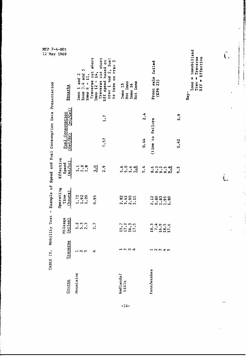
a. Map out a test course across natural terrain at the desert provingground or other desert test area that shall include the approximate mileage acrosseach type of terrain as shown in Table I, and Table II as appropriate to thetype of vehicle to be tested.
-12-

__ MTP 2-4-00112 May 1969
41 00 0 00 0cc4 coC OD Ccnf 00co -
wJd 00C 0 0
co410 0 00 0nr 1 C4 .t cl C*t- c)
E-4 .-
410r-4 4Ja 0
.- 4- lý4
E-4 C:I- 00 I1 00 i~'ca 1 4 ( I a 4'J 140 ca 0
.4.-144 4
u 04- I3 r
.r4
I-'A
4-13-
WT? 2-4-00112 May 1969
01
14 a 0 cw >
.0 a.0 :31A
C'40 >~ 0 .
0.- u -u .0 "a 14~10.-c 01I0 01x~ an .~ ~ >
0. ~ C~ 1.-4 010 01 ý4 E 4 &-4 twz1- 4 > >10>J " 00,4m0 000 000 00 caJ m cA j 0r2 1 $4"-d$U4O $4 0 0 600
C: B1 ~ E- H -444Ji i-z -4~v 1-go
$4
0 4
00
00 [Z m- ~ -
V10
0 Q.-14 c I ý . a: 01 a; ý
4401
x 0
r.. 0 01 CI 1 ý rýr ý""4
-0
($4
49 '.4 C1 W 1 C
0.~r 10w
0 0 a c
A-14

MTP 2-4-001* 12 May 1969
NOTE: Figure 2 illustrates the desert terrain types considered.AppendixA describes these terrain types in terms of physio-
graphy and typical surface conditions.
b. Instrument the test vehicle with an external odometer not attachedto the vehicle's wheels.
6.1.10.3 Durabilt•, rests
Prepaiacion for durability tests shall be conducted as describedin 6.1.10.1 and Table 1:1.
6,1.11 Exposure and Stozage Tests
6.1. 12 Desert Exposure and Storage
Preparation for desert exposure and storage shall be conducted asdescribed in paragraph 6.1.3 and criteria of Table IV.
6.1.12.1 Security from Detection
Preparation for security from detection shall be conducted asdescribed in MTP 2-2-615.
6.1.13 Human Engineering
Preparation for human engineering tests shall be conducted asdescribed in MTP 2-2-803.
6.2 TEST CONDUCT
6.2.1 Performance Tests
6.2.1.1 Octane Requirements
Determine the test vehicle's octane requirements, under variousoperating cGnditions as follows:
a. Road-Load Acceleration
1) Warm up the engine, using a specification fuel, by operatingat high speed with full throttle, until temperature stabili-zation is achieved, and record the following:
a) Specification fuel usedb) Fuel octanec) Fuel pressured) Stabilization temperature at all instrumented points
-15-

MTP~ 2-4-00112 May 1%99
J LD
IIL
A 22
'iI It
cra 0i ~2
0 _ 1 I 0,i2
I go
3~* 02
021>i E- 4
II~ o
%~\~ "I, -
Ib
\N
&'''~

MTP 2-4-00112 May 1969
0 v 0
410 -E0"" 3'.
. I. 5c olo o. 'o v
0.4 00 0. 4
Uo 6w *d CI ep 31443C
wto i @0 te, 11
C14- 4
C4 4 e 11
ze. 0- Q0
Ile 0 0 4' '* .u e 4'g.o 0 0
eC0 0 0 0 0 4 0An 0 &M 0 In04 ell Cd 04 C
1. S. 0
49 I0~ 0 0 0 0
as 0
-. ~C v1. C d 4'
40 X
0 w o0U 0 0 - C C* . 0 0 0 0 0. V ,)L
-0 Cl 0

IMTP 2-4-00112 May U169
Z. c 0 S0-
x ol 00.
c20%- 40 0
Zn-.
2 c fta- ato ~ - -. - 4.. /4 . (.
g
10 v
uI 0. 0 AI n
C44 CI(4 CN
u :1. 0 0 0. 0 -
.5.C~ 00 0 0 0 0 0 0
0 C02 0 0 0 0 0 0 .,)
u. - . 1 0 r.c cso X14x 4 -l C4 en
di
* .54
. 4. 4A 4 '4
*i 0 04A
--. ad
0 >4 .. 4 > c4 'av
-V MJ x COa aC.0 4rv :30 0m - n:
0 . - 0. N 1 0 0 24

MrrP 2-4-C-31
12 May 1969
I -4V4 C4 0%
.4
*1 IE-4Ma ca to
-. 41
0 to 0 0 0
4V 0 - j 4 -
14
UI 48 0 -,4 -4 W U *ol .0 00 00
w 440 6 4 04i 44 0 041w 0 e r. -
>00x1 I,-A9 C c o 4-
0o -0 a s --4 w. ~0.oo 0 0 _ 0 caca4e ý
I~~~4 &44A44J'.J. 00 'U
p0 0~ -- > w~ 0 w 00 0
go C: 0 u 00 p0 4 0 0 0 a U0 c0 0 0 cc rz 0 0 E0 C0 04 w41~ -QA4 414 o 0 4). 41 4.4e 0. Ho~ 0 Go.- g. u VU -4 -4oCo t' ) 'U 14 W4 wX~ 4)- 000C 0tw) 0 10. 00c c $ M-i C -1. -4I4" 44 0 4)wM 40 4 1) - -w c
u .0 .00
,4U.. toU 0 0 '4-40 to410. 0 co O -,q U . e$4 (A0ý n10..'U 0o 41 $ 041!) 1 0-. Civ 0 m c $41 $4)0 p 4 -IL
0. p o .
14'- 0 0$ r L) : A(CI -, 0w :j 0.>'I'U 0
'-190 >.

MTP 2-4-00112 May 1969
C *'Uf
4J L) En t L' Ian' in0 V C4 CJC.I " " -4 " '4. cn r,.4 a 40 4 0 It cJ ^4j GogU4 4. 6.. 0,I 14 as4
-4* 02 z))'.)U . 0
a,.- -4 oJI
" "4 U1 U 0 0
03 02 4j0 4--1 u -J0 4J 02 2 00 $4 bo C000 w-00 r000 w 00 $4 . I.
X~~~ ~ q) 0 GJU @OU OJ )01 0 2
41 $4 0 w $4 w $W4z$4J " 004 0 a,$J 00,43 " oo 0 U
$4- 1.' $41. w.4.$ -- aa, aM- 9:2a 'U02 C:W *U0 =- -4 C:-4
4) V U),0 a 0aV02 0 0) V 030--I.o1 w0-' toU 4)( ) a 4 H"
"4 m44 W T00
o1 1'4 u2 0mU4 w 0, ) a,0
04 u bo$ 0 be 000 U a,414V4 0 r 0 00 004 -444 V -4
0 9 r-4 :3 4 (D~~ -4 > -002 w $4 0(U 02 '-4 (L '-4 'a 0- 0) b 0 () (AuX m020> $40 M0.~ 42 CO-44) 9 0 UJ
C)) 0 0) 010 4J -4 00 $4 0.0U> *.4 m0 cc02 0002( r 0 CO 0O2O-4 m. X 0 $4
.0 v w C w 020U02 .0 0 .f O40 M $4 m2 W -r4 u"-.4 M024 U0-4 0) () x U 0 a2 U: u w ca 400 a) 1 C 0 U41 I 020 u 02)-o4 a, 4. 4) 00 co p
2 -ý4 $4X -r4 0 x -A .- a 14o 02c $40w -4 0 kH0 X020 $4 0) 14OOX U '-2 *4) ý:5 0owZ44 1-. -fU'. . 0~' -4 b Xb .0.1 0) N:U ~ 0 02 4-o 0 *6 0 00 '-0r200 -L U0'a'.C. 02-ý4 P00 '.' 020202a
C: 0200.2 4J -4 b00r -r40 r. " -14 0-4'-4:0 W- 4H~J4) C: "q C C-4. (o .) " 20 0 -14 UN- -4S-4i x
02002"4 0%202 02 -A ~ -x w ~ ' !d 0),- N S- A J )H 0$42 V>.02 0,o2 00.0c202 C 4 w $40(2$4 0 w$v 4 *r4 w
E-0 pca(L ) 1 ccc0) 4 c0UZ.- HC) 0~ H0 4 - 0 pH 0. p
H 0 -4
0 -- W0 -4 02 -
02 :3 4J U0 U0r I 4 ~ $40 02 U P1 W2 -1- '-0'
-402 W 0)0: 0 0. m0 0 2O- '-4 .0 4 C.0U 02 c U mU 1 0 10 '-40 CO 02i.,4 C: -A- ' 02' a H V r " 0 4' (0 M0 600CLcJ 4 4J-Q0'U 4J0' '0* 021 U2 0202c . a0 0 m22J m 4- r2 M J A C020 0 Co -.- Q) 4JC/ 4-1 00 CL MQ02c 0.00 a)JO ca 4-"0)$4 aUc 0 ) I ,to r $4P 1)4 pa 02a I.,0u0p 024. .- 4 ) 10' U1>
30 0H 14 r-f H$ p ca 0 w p cu 0 -4 *r4 C 00w
-20-

AV, MTP 2-4-00112 May 1969
041' 0
$4.
$4 '.4
0 -,4,$4 0 4JI
0 0 0 0-4$C0c 0 0o 4J
LW 44 -H W -020 1- 0 00
m- H0 .1 0
041
ý4 $0 u0
44 0 V00 40
U$4 M4. 0 N 0 - '.
Cr 0 4-' Uw 1- 4 0 'U0 . 0) 0 -4
00r-4 $4 V
0 0 w4 cu'-4 0)4 00
O~ a. 0 Wi'o0 0 4 0- 0 Ur'09 X w 0 r.0-4.4
U 0 0) f 0 0 r z ,$4 N w $4 '= u- w
H4 'U 0U 0H , W O P 4 H
-4U E-r w- U $. 14 4J"" ~ W ' 0004. w
U.0 00,i. 10 ww iUN s24 U 0 U04COC/3G' U.40G.' -. 4
-21
MTP 2-4-00112 May 1969
NOTE: Suspend the acceleration test if any air-cooled engine sparkplug gasket thermocouple registers an excessive temperature.
A temperature above 525*F shall be considered excessiveunless the engine manufacturer has established another limit.
2) Connect the detonation sensors, if applicable, to theirrecording equipment and verify their operability. Recordthe rating and location of detonation.
NOTE: 1. Suspend the acceleration test if the detonation ratingis seveze.
2. Detonation (knock) is rated as having "0", "A", "B"or "C" intensity, as follows:
a) "(" knock is the absence of any detectable detonation.b) "A" knock is a barely detected detonation.c) "B" knock is a distinct detonation producing os-
cilloscope pulse amplitudes no greater than pulsesproduced by valve closures.
d) "C" knock is a severe detoxaýion producing pulseshaving amplitudes greater than those produced byvalve compressors.
3) Select a gear ratio which will allow an engine accelerationrate as specified in the test plan. The acceleration rate
should fall between 30 rpm/sec and 60 rpm/sec depending onthe vehicle under test. If no gear ratio is capable of anysuitable manner Lo obtain the required acceleration. Recordthe method used to obtain the required acceleration, theacceleration rate, and, when applicable, the loading method.
4) Record the following meteorological data:
a) Wet bulb temperatureb) Dry bulb temperature
c) Barometric pressure (absolute)
5) Accelerate the test vehicle with wide open throttle fromminimum practical speed to maximum rated speed And record
the following:
NOTE: Ease off on the throttle, if necessary, to prevent severeor prolonged knocking. An air-cooled engine cannot tolerateknocking for more thdn 30 seconds without severe damage.
a) Fuel pressure
b) Stabilization temperature at all instrumented pointsc) Engine speed at which knock is detectedd) Engine speed at which knock disappearse) Engine speed at each occurrence of knockingf) Severity of each occurrence of knocking
-22-

K,? 2-4-001is 12 May 1969
6) Rapidly decelerate the test vehicle by braking.7) Repeat steps 5 and 6.8) Repeat step 7.9) At the completion of step 8, perform the following:
a) Switch to the highest octane rated primaryreference fuel.
b) Scavenge the fuel system by running the engine outof fuel twice.
NOTE: If a quick-disconnect hose is used, the hose may bedisconnected until fuel pressure falls to zero, thenreconnected, thus scavenging the fuel lines withoutstopping the engine. With a fuel-injected engine, thepressure cannot be allowed to drop; instead, run the enginethree or four times as long as would be required to run asimilar carbureted engine out of fuel.
c) Record the following:
()Test fuel used(2) Fuel octane
10) Repeat steps 4 through 8.11) At the completion of step 10, repeat steps 9 and 10 using
the highest rated severity reference fuel.12) Repeat steps 9 and 10 using the primary reference fuel
of step 9 having the second highest octane rating.13) Repeat step 12 using the severity reference fuel of step
11 having the second highest octane rating.14) Repeat steps 12 and 13 using decreasing octane rated
gasoline until severe knock develops.
b. Road-Load Deceleration:
1) Warm ,, the engine, using a specification fuel, by operatingat high speed with full throttle, using a loading device(dynamometer) to limit road speed to a safe figure, untiltemperature stabilization is achieved, and record thefollowing:
a) Specification fuel usedb) Fuel octanec) Fuel pressured) Stabilization temperature at all instrumented points
2) Connect the detonation sensors to their recording equipmentand verify heir operability.
-23-

MTP 2-4-00112 May 1969
3) Select a gear ratio in which the loading device (dynamometer)will decelerate the test vehicle as specified in the testplan. The deceleration rate should fall between 30 rpm/secand 60 rpm/sec, depending upon the vehicle under test, whenoperated at full throttle.
4) Record the following meteorological data:
a) Wet bulb temperatureb) Dry bulb temperaturec) Barometric pressure (absolute)
5) Decelerate the test vehicle from maximum rated speed tominimum rated speed, at full throttle, and record thefollowing:
a) Fuel pressureb) Engine temperature
NOTE: Suspend the deceleration test if any air-cooled enginespark plug gasket thermocouples register an excessive temperatureUnless otherwise stipulated by the engine manufacturer,a temperature of 5250 F. shall be considered excessive.
c) Engine speed at which knock is detectedd) Engine speed at which knock disappearse) Engine speed at each occurrence of knockingf) Severity of each occurrence of knocking
NOTE: Suspend the deceleration test if the detonation ratingis severe, or if the spark plug thermocouples of anair-cooled engine register an excessive temperature.
6) Stabilize the engine temperature by operating Lhe vehicleat fuel rated engine speed.
7) Repeat steps 5 and 6.8) Repeat step 7.9) At the completion of step 8, perform the following:
a) Switch to the highest octane rated second specificationfuel.
b) Scaven3e the fuel system by running the engine out offuel twice or as indicated in the NOTE of paragraph6.2.1.1.a.9.
c) Record the following:
(1) Test fuel used(2) Fuel octane
10) Repeat steps 4 through 8.11) At the completion of step 10, repeat steps 9 and 10 using
the highesL rated severity reference fuel.
-24-

MTP 2-4-001
12 May 1969
12) Repeat steps 9 and 10 using the specification fuel of step 9S~having the second engines octane rating.
13) Repeat step 12 using the specification fuel of step 11 havingthe second highest octane rating.
14) Repeat steps 12 and 13 using decreasing octane rated gasolineuntil severe knock develops.
c. Full Load, Full Throttle:
1) Warm up the engine, using a specification fuel, by operatingat high speed with full th•rottle until temperature stabili-zation is achieved and record the following:
a) Test fuel usedb) Fuel octanec) Fuel pressured) Stabilization temperature at all instrumented points
2) Connect the detonation sensors to their recording equipmentand verify their operability.
3) Attach a loading device (dynamometer) to the test vehicle andselect a gear ratio, appropriate to the characteristics ofthe loading device, which will hold the vehicle road speedto a minimum.
4) Operate the vehicle at full throttle under load until thetemperature stabilizes, and record the following:
a) Engine rpmb) Stabilized temperatures at all instrumented pointsc) Fuel pressured) Severity of knock at each cylinder, if possible
NOTE: Suspend the full load, full throttle test under thefollowing conditions.
(1) The detonation rating is severe.(2) Engine temperatures become excessive. Air-cooled
engine temperatures are considered excessive when thespark plug gasket temperature reaches 525 0 F or asstipulated by the engine manufacturer. Licuid-cooledengine temperatures shall be considered excessive asdirected in the test plan or specified by the enginemanufacturer.
5) Repeat step 4 using engine speeds in decreasing increments of200 rpm/sec down to minimum practical speed.
6) At the completion of step 5, perform the following:
a) Switch to the highest octane rated primary reference fuel.b) Scavenge the fuel system by running the engine out of fuel
Lwice or as indicated in the NOTE of paragraph 6.2.1.1.2, 9.
-25-

MTP 2-4-00112 May 1969
c) Record the following:
(1) Test fuel used(2) Fuel octane
7) Repeat steps 4 and 5.8) At the completion of step 7, repeat steps 6 and 7 using
the highest rated severity reference fuel.9) Repeat step 7 using the specification fuel of step b
having the second highest octane rating.10) Repeat step 9 using the specification fuel of step 8
having the second highest octane rating.11) Repeat steps 9 and 10 using decreasing octane rated
gasoline until severe knock or excessive temperaturesdevelop.
6.2.1.2 Fuel Vapor Handling Capability
Determine the test vehicles fuel vapor handling capability undervarious operating conditions as follows:
a. Full Load Test:
NOTE: This full-throttle, full-load test is most suitable formedium and heavy tactical vehicles and all combat vehicles.
1) Attach a field dynamometer to the test vehicle.2) Drain the fuel tank and fill it to 80% capacity with
the test fuel.
NOTE: For gasoline-powered test items, use a test fuel blendedto simulate, at the forecast ambient temperature, thevolatility at design temperature of the most volatilespecification fuel. For other than gasoline-fueledvehicles, use specification fuel of the highest volatility;i.e., lowest temperature for V/L = 20.
3) Collect a tank sample of this fuel just prior to beginningtesting and label the sample "SAMPLE 1". Refrigerate thesample for subsequent analysis.
4) Perform a warm-up cycle as follows:
a) Select a gear range that will provide maximum heatrejection and a road speed of less than 15 mph undermaximum rated load applied by the dynamometer. Recordthe gear range and speed obtained.
b) Operate the test vehicle on a level paved course atfull throttle under full load until all temperatures
-26-

I
I •MTP 2-4-00112 May 1969
are stabilized or the vehicle has been operated for
a maximum of 30 minutes. Record the temperature andpressure of all instrumented points.
c) Drive the test vehicle into a "soak" shelter.d) Idle the test vehicle for two minutes and shut down
the motor.e) Collect a fuel sample, "Sample 2", from the fuel tank
when the gasoline reaches maximtum temperature or thevehicle motor has been shut down for 15 minutes, which-ever is longer. Record the temperatures of all instru-mented points and shut-down time.
5) Perfotm a drawbar cycle as follows:
a) Restart the engine and record the following:
(1) Time required to restart the engine(2) Number of attempts required to start the engine
b) Accelerate the vehicle, in the gear range of step 4a,with no drawbar load, to the speed of step 4a.
c) Apply the drawbar load and record the drawbar pull.d) Operate the test vehicle under load until the temperatures
stabilize, or a maximun of 20 minutes, whichever isshorter.
e) Stop the test vehicle in the "soak" shelter and idlethe engine untIl the fuel system temperatures reachmaximum or for 10 minutes, whichever is shorter.Record the idling time and temperature and pressureof the instrumented points.
f) Collect a fuel sample from the fuel tank and label it""SAMPLE 3".
6) Repeat stepE 4 and 5 alternately, taking consecutivelynumbered fuel samples, until the severest cycle is deter-mined. Rate severity of cycles by degree and frequency ofsymptoms of premature vaporization of fuel.
Symptoms, to be rated, in order of decreasing importance, are:
a) Stalling or complete inability to start.b) Overheating.c) Reduced drawbar pull. of 25% or more.d) Misfixing.e) Difficult starting requiring more than ha]f the maximum
containers cranking time.f) Bucking or surging.g) Rough idling.h) Black exhaust smoke.
7) Repeat the severest cycle until one of the following has beenachieved:
-27-

lTP 2-4-00112 May 1969
a) Complete vapor lock is encounteredb) A minimum of 4 cycles have been completedc) Test fuel is consumed
b. Cross-Country Test:
NOTE: 1. This near-full-throttle test is intended for high-mobility vehicles; not intended for continuous, full-load service. It shall be performed in desert terrainappropriate to the intended mission of the vehicle,such as level sand, dry washes, or a desert cross-country course.
2. Test the vehicle with a towed load when appropriate.
1) Drain the fuel tank and fill it to 80% capacity with testfuel as described in the NOTE of paragraph 6.2.1.2.a,2.
2) Collect a sample of the test fuel immediately before begin-ning testing, label it "SAMPLE 1", and refrigerate it forsubsequent analysis.
3) Perform a warm up cycle as follows:
a) Select a gear range, which will provide maximum speedover the chosen terrain. Record the gear range andtype of terrain.
b) Operate the vehicle at normal speed for 40 minutes,then stop in the "soak" shelter. Record the vehiclespeed.
c) Idle the vehicle for two minutes.d) Shut down the vehicle until the fuel system temperatures
reach a maximum, or for 15 minutes, whichever is longer.Record the temperature and pressure of the instrumentedpoints and shut down time.
4) Perform a full-throttle cycle as follows:
a) Restart the engine and record the following:
(1) Time required to restart the engine(2) Number of attempts required to start the engine
b) Accelerate the test vehicle at fuil-throttle to maximumsafe speed, and operate it at maximLm safe speed for40 minutes. Record the maximum safe speed.
c) Stop the test vehicle in the "soak" shelter and idlethe engine until the fuel system temperatures reachmaximum or for 10 minutes, whichever is shorter. Re-cord the temperature and pressure of the instrumentedpoints, and the idle time.
-28-

MTP 2-4-001
12 May 1969
d) Collect a fuel sample from the fuel tank and labelit ~'SA!iPLE 2".
5) Repeat steps 3 and 4 alternately, taking consecutivelynumbered fuel samples, until the severest cycle, as ratedin paragraph 6.2.1.2, aob, is determined.
6) Repeat the severest cycle until a complete vapor lockhas been achieved, or a minimnit of four cycles havebeen completed.
NOTE: Fuel shall be added only to obtain the requirementsof step 6.
c. Highway Tests:
NOTE: This test is intended for vehicles designed for highwayuce or for tactical trucks. It is performed on steepdesert highways such as the Daylight Pass or Oatman-Topcockcourses established for tests based at the USATECOM permanentdesert test facility, Yuma Proving Ground.
1) Operate the test item for a minimum of 1 hour, with itsrated towed load, if appropriate. Record the length ofoperation and presence of load.
2) Drain the fuel tank and fill it to normal fuel level asdescribed in the NOTE of paragraph 6.2.1.2.a,
NOTE: Deliver the test fuel in sealed 55-gallon drums andshelter them to keep its temperature below ambientair temperatures.
3) Collect a sample of the test fuel immediately beforebeginning testing, label it "SAMPLE 1", and refrigerateit for subsequent analysis.
4) Perform a warm-up cycle as follows:
a) Operate the test vehicle for a minimum of 10 miles
in gear ranges that provide the best speed on gradesand best acceleration. Recora the gear range usedfor each percent of grade.
b) Stop the vehicle in a "soak" shelter at the foot of
the severest 5 miles of uphill grede and idle theengine for two minutes.
c) Shut down the vehicle until the fuel system temperaturesare a maximum or for 15 minutes, whichever is first.Record the temperature and pressure of the instrumentedpoints and the shut down time.
d) Collect a fuel sample from the fuel tank and label it."SAMPLE 2".
-29-

MTP 2-4-00112 May 1969
5) Repeat steps 4 and 5 alternately, taxing consecutivelynumbered fujel samples, until the severest cycle, as ratedin paragraph 6.2.1.2 a,b is determined.
6) Repeat the severest cycle until the fuel supply is consumed.
NOTE: Add fuel to the fuel tank only when the tank is nearlyempty.
d. Acceleration Test:
MOT : 1. This road-load test is modeled on the autoamotive industrystandard test of fuel vapor handling capability esta-blished by the Coordinat.ag Research Council, Inc.,(CRC). This procedure is recommended for measuring themaximum gasoline vola-ility tolerated by a vehicle and isparticularly suitable for use with tactical and commercialtype vehicles.
2. The test is performed on a dynamometer course or otherlevel paved desert course provided with a 'so3k" shelter.
1) Drain the fuel tank and fill it to 20% capacity with aspecification fuel having a volatility of 6 through 14 Rvp.
2) Determine a baseline for measuring acceleration, under ambientconditions as follows:
a) Using the fuel blend of step I: .
(1) Determine the vehicle's acceleration to obtain theaverage speed the test vehicle is capable of reachingin five seconds.
(2) Record the follcwing:
(a) Acceleration rate(b) Vehicle speed(c) Vehicle inspection
(3) Repeat steps 1 and 2 for the following speeds:
(a) 25% of rated vehicle speed(b) 507. of rated vehicle speed.(cl 75% of rated vehicle speed(d) 100% cf rated vehicle speed
b) Repeat step a with the vehicle going in the oppositedirection.
-30-

XTP 2-4-00112 May 1969
S3) Warm up the test vehicle by operating it for 20 minutes
at its maximum sustained road speed, using the fuel blendof step I. At the completion of the 20 minutes, stop thevehicle in the "soak" shelter.
4) Perform an idle-soak cycle as foilows:
a) Idle the engine for 10 minutes in the "soak" shelterb) Accelerate the vehicle at part throttle to the 5
second average speed of step 2a.l. Record the timerequired to reach speed.
c) Accelerate the vehicle at full throttle to 10C7°
of its rated speed apd record the time requiredto reach its rated speed.
5) Perform a hot-soak cycle as follows:
a) Stop the vehicle in the "soak shelter"b) Idle the engine for 1 minute, and then shut it offc) Leave the engine off for 10 minutesd) Restart the engine, and record the following:
(1) Time required to start the engina(2) Number of attempts required to start the engine
e) Accelerate the vehicle at part throttle to the 5second average speed of step 2.a.l. Record the timerequired to reach speed.
f) Accelerate the vehicle at full throttle to 1007% of itsrated speed and record the time required to reach itsrated speed.
6) Repeat steps 4 and 5 alternately until the severest cyclecan be determined as judged by the criteria listed inparagraph 6.2.1.2 a,b.
7) RepeaL the severest cycle, until complete vapor -ock occursor until acceleration times increase by 50%.
8) Repeat steps 4 through 7 with test fuels having Rvp's of7 through 14 psi in steps of I psi.
6.2.1.3 Compatibility with Specification Grades of Fuels and Lubricants
The compatibility of the specified fuels, lubricants, hydraulicfluids, or related materials, under desert environments, shall be determinedas described in the applicable sections of MTP 2-2-701.
6.2.1.4 Fuel Consumption
Vehicle fuel consumption under desert conditions shall be determinedas described in MTP 2-2-603 and include the following on a daily basis:
a. Type of fuel usedb. Engine operating hoursc. Mileage traversedd. Ambient temperatures
-31-

MTP 2-4-00112 May 1969 V6.2.1.5 Engine Cooling System Adequacy
The engine cooling abiiity of the test vehicle, operating under full
load, road load, and the effects of controlled differential steering on
the engine cooling system shall be determined as desccibed in the applicable
sections of MTP 2-2-607.
6.2.1.6 Braking Adequacy
The braking ability shall be determined as described in MITP 2-2-608.
6.2.1.7 Drawbax Pull Test
The test vehicle tractive effort shall be determined as describedin MTP 2-2-604.
6.2.1L8 Air Cleaner Adequacy
Determine the adequacy of the test Vehicles air cleaner under varicusoperating conditions as follows:
a. Operate the pilot vehicla and test vehicles(s) over the dust
course maintaining a normal convoy between the lead (pilot) vehicle and test
vehicle(s).
NOTE: Speed and operating mode of the convoy shall be selectedas appropriate to the intended mission of the test vehicle.
b. Record the initial restriction across the air cleaner.c. Operate the vehicle(s) on the dust course until one of the
following occurs:
1) Air cleaner restriction increases to the figur2 at which
servicing is recommended by the manufacturer's instructionsor technical manuals.
d. Record the following:
) Engine revolutions
2) Average vehicle speed3) Kelative humidity4) Ambient wind speed5) Final restrictions across the air cleaner
6) Reason for test termination7) Mileage traveled8) Operating time
e. Service the air cleaner as directed by the technical manuals or
manufacturer's instructions and obtain a sample of the dust for laboratoryana lys ic.
-32-

I4TP 2-4-00112 May 1969
f. Record the time required for servicing.g. Repeat steps a through f with the test vehicle(s) operating oneither the cross-country or gravel course, whichever is more appropriate to
the intended use of the vehicle.h. Repeat steps a through g without a rlot vehicle or convoy.i. Using the mileage values obtained for the dust and cross-country/
gravel courses with and without a convoy, lay out a test course that will allowthe vehicle(s), with and without a convoy, co travel 2/3 of the tire on thedust course and 1/3 of the time on the gravel or cross-country course, whicheveris appropriate. Record the mileages:
j. Record the test vehicle(s) restriction across the filter.k. Operate the vehicles with a pilot vehicle, in convoy, until the
conditions of step c are met, and perform the following:
NOTE: Operations shall be suspended when wind speed exceeds 15 mph.
1) Collect samples of dust from the air stream just ahead of thetest vehicle(s) air intake over each of the courses foranalysis of dust concentration, and record the following:
a) Direction of vehicle travelb) Wind speed and direction
2) Record the following:
a) Total mileage traveled:
(1) Dust course(2) Gravel/cross-country course
b) Engine revolutionsc) Average vehicle speedd) Relative humiditye) Ambient wind speedf) Final restrictions across the air cleanerg) Reason for cycle terminationh) Operating time
3) Service the air cleaner as directed by the technical manualsor manufacturer's instructions and obtain a sample of the dustfor laboratory analysis.
1. Repeat step k without a convoy.m. Repeat steps k and 1, alterrately, until a minimum of four complete
cycles (four in convoy, four without convoy) have been completed, making adjust-ments in mileage, as required, to all for 2/3 of the mileage traveled to be onthe dusc course, and 1/3 to be on the gravel or cross-country course, as appro-priate.
n. At the completion of testing, perform the following:
"-33-

iMTP 2ý4-00112 Mdy 1969
1) Clean the air filter element and inspect it for the following:
a) Signs of wear, deterioration, or damage.b) Signs of abrasion caused b; high-velocity aad
particles.c) Embrittlement or separation of materials due to
heat and desiccation.d) Ruptures or separations caused by repeated removal,
cleaning, and replacerent of the filter element.
6.2.1.9 Tire and Track Testing
Tires and tracks designed for specific vehicles shall be tested,
with that vehicle, under desert conditions, as described in MTP 2-2-7%.
6.2.2 Mobility Tests
6.2.2.1 Sand Mobility
The ability of the test vehicl^ to operate over sand shall bedetermined as described in MTP 2-2-619.
6.2.2.2 Desert Cross-Country Mobility
Desert cross-country mobility tests shall be conducted as follows:
a. Operate the test vehicle over its selected course for thenumber of miles prescribed for its group in Table I and rable II. The requiredmiles should be driven over each type of terrain which is passable by the testitem within the following limitations:
1) Certain types of terrain will be essentially impassableby certain vehicles within a given group.
2) When the test item is unable to make reasonable progressin difficult terrain, the test over the terrain may besuspended on expiration of the number of operating hoursshown in Table I or Table II at the discretion of thetest project engineer.
NOTE: The objective of practical tests precludes arbitraryjudgments about mobility in particular areas beforereasonable efforts actually are made to negotiate such
terrain.
b. Record the following:
1) Mileage covered, and operating time required for eachterrain,
-34-

MTP 2-4-00112 May 1969
io
2) Time spent in towing, when required.3) Operator/organization servicing and repairs and time to
perform them.
NOTE: Do not include time spent waiting for assistance, equipment,or supplies in towing and/or service/repair time.
4) Fuel consumption, for each type of terrain, as describedin MTP 2-2-603.
5) Reason for suspension of test prior to achieving fullmileage, when applicable.
c. Wheeled Vehicle Tests:
1) Group I Vehicles - Group I vehicles, identified in Table IIIshall be tested in accordance with paragraphs 6.2.2.3 aand 6.2.2.3 b and Table V.
2) Group II Vehicles - Group i1 vehicles, identified in Table III,shall be tested in accordance with paragraphs 6.2.2.3 a and6.2.2.3 b, Table V, and the following special procedures.
a) Dump bodies:
(1) Raise and lower dump bodies the equivalent ofat least once for every ten miles, with completedumping and reloading at the completion of testing.When practicable, this test should be made on actualjobs requiring dump truck service.
(2) Record the ability of the dump bodies to operatesatisfactorily.
b) Crane and wrecker trucks:
(1) Operate crane and wrecker trucks with all
accessory equipment properly stowed.(2) Evaluate the ability ot the crane and wrecker to
assist in performing maintenance, supply and re-covery operations by the following methods:
(a) Perform lifting operations, simulated oractual, for two hours after each eight hours ofroad operation.
(b) Perform one simulated or actual recovery aftereach 25 miles of operation.
(c) Operate the crane at full load using all ac-cessorips and with the veicle repositionedat least four times during each pcriod oflifting operation.
-35-
L

MTP 2-4-00112 May 1969 '
'1 -0 00 0 to 13 c 0 a'4
In 5 4n C-1
0 0 0 I lL 4
U 0- 0 "0 CU
0
00 0. 0n
NI
1. 0 0 Il
U4 0) - 0
oc
P4 C 4N.
454
I.Q
0. '.-36-

MTP 2-4-00112 May 1969
(d) The crane and winch shall be operatedsimultaneously once during each recovery,if practical.
c) Ambulances, tankers, and cargo vans:
(1) Ambulances shall be loaded and unloaded once
during each 8-hour shift.(2) Tankers shall be loaded and unloaded once for
each 40 test miles. A container shall beavailable to store the unloaded fluid.
(3) Cargo van bodies shall be loaded and unloadedeach 100 miles of test operation.
NOTE: Unloading and reloading vehicle bodies and tanks is a timeconsuming and expensive operation. Limited funds or short-time test schedules necessitate keeping these operations toa minimum.
(4) Pumps and other mounted equipment shall be operatedas test conditions require. During extended periodswhen there shall be Do normal requirement to operatethese components, they shall be operated sufficientlyto determine operability and the absence of leaks and,musual noises.
6.2.2.3 Durability Test
Durability testing the vehicles shall be determined as follows:
a. Operat, the test vehicle over its selected course. Reasonableand practical speeds for the particular course conditions shall be maintained.Preventive maintenance shall be performed as prescribed in the applicableinstruction manuals. In addition, vehicles, their accessories and kits shallbe inspected at least once during each eight hours of operation for deficiencies,damage or unusual wear.
b. Record the following for each vehicle tested:
1) Vehicle mileage as measured by the odometer.2) Engine hours (total running time).3) Engine hours (idling time and operating time).4) Fuel consumption as described in MTP 2-2-603.5) Component failures,6) Vehicle performance deficiencies.7) Parts Mortality.
8) Required component adjustments.9) Ambient conditions and surface conditions affecting.
performance of the test vehicle.10) Maintenance time required, and man-hours of labor required
at each echeloa of maintenance.
-37-

.WP 2-4-00112 May 1969
NOTE: The desert cross-country mileages prescribed in Tables IIIand V, are identical to those shown in Table I and 11 fordesert cross-country mobility testing. The desert roadmileages are proportioned to desert cross-country mileagesas intermediate-climate ro.3d mileages are to cross-countrymileages of MTP 2-2-506, and MTP 2-2-507, as by themultiplying factor of Tables IV and V. The difference inmileage is intended to reflect the relative scarcity of roadsin the world's desert regions, the good trafficability ofregions abounding in desert flats, and the probabilitythat vehicles used in desert military operations will tendto be driven largely over unimproved natural surfaces.
11) Groups III through V vehicles - Croups III threugil Vvehicles identified in Table III shall be tested inaccordance with paragraphs 6.2.2.3 a and 6.2.2.3 b, andTable 1II
12) Group VI vehicles - Group VI vehicles, identified inTable III shall be tested in accordance with paragraphs6.2.2.3 a and 6.2.2.3 b, Table III and the followingspecial procedures.
13) Groups VII and VIII Vehicles - Groups VII and VIIIvehicles, identified in Table III shall be tested inaccordance with paragraphs 6.2.2.3 a and 6.2.2.3 b.
a) Measure the capacity of pumps at the start and Lconclusion of testing.
b) Operate all mounted equipment, ladders, etc., todetermine adequacy of vehicle operation.
c. Tracked Vehicle Tests
1) Groups I through V vehicles - Groups I through V vehiclesshall be tested in accordance with paragraphs 6.2.2.3 a,and 6.2.2.3 b, and Table III.
2) Accessory and Vehicular kits shall be tested in accordancewith Table III and the following shall be recorded.
a) Item under testb) Vehicle mileagec) Hours of operationd) Component failurese) Lubricant used, when requiredf) Parts mortalityg) Required component adjustments, when applicableh) Performance deficiencyi) Conditions affecting accessory or kit performance
-38-

HTP 2-4-001
12 May 1969
TABLE VI. Checklist for Desert Human Engineering
Evaluation i~f Vehicle Design
Human Factor Possible Condition
Heat Stress Any symptoms of incioient heat stroke?Any symptoms of incipient heat exhaustion?
Any occasions wt.en heat-induced fatigue delayedor curtailed operations?Rate heat encountered in operation of the testitem as compared with a similar standardvehicle:
Cooler, hotter, much hotter?Comfortable, uncomfortable, severe,intolerable? What standard vehicle?
Burning Temperatures Any encounters with painfully hot parts?What parts? Specify. C) isify as frequentlyused controls, occasionally used controlsor handholds, normally accessible parts, orinfrequently touched parts.Any burns suffered:
First, second, or third degree?
Ventilation Does air in vehicle become uncomfortablydusty, bad enough to require dust mask orgoggles? Do objectionable fumes get intovehicle - exhaust fumes, other fumes?Do fumes irritate eyes, respiratory tract,skin?
WARNING: Fumes from pet' oleum-fueled enginescontain carbon monoxide, a colorless,odorless gas which has cumulativetoxic effects and is lethal in highconcentrations. Operation shall besuspended if exhaust fumes areregularly present in noticeablequantities.
Noise Does noise interfere with vocal communication?Any painful or uncomfortable noise levels?Any after effects from noise?Any need for ear plugs, etc?
Visibility Any visibility problems in operation of thetest item?Any difficulty reading gages, indicators,instruction plates?Any problems due to contrasting brightness
levels, glare, reflections?
-39-

MTP 2-4-00112 May 1969
(Checklist continued)
Does airborae dust interfere withvisibility?Do dust accumulations affect vision?Does hot-climate operating mode altervisibility in any respect?
6.2.2.4 Security from Detection
Determine the test vehicle's security from detection as describedin HTP 2-2-615.
6.2.2.5 Maintenance
Determine the test vehicle's maintenance as described inXTP 2-2-503.
NOTE: All necessary deviations from the preestablishedprocedures shall be noted for inclusion in the test report.
6.2.2.6 Human Engineering
Determine the test vehicle's human engineering aspects asdescribed in MTP 2-2-803.
6.2.2.7 Safety
Determine the vehicle safety test as described in Uii 2-2-508.
Ii
-AO-
Sw L

SI rP 2-4-00112 May 1969
6.3 TEST DATA
6.3.1 Initial Inspection
Record the following for each vehicle tested
a. All deficiencies encounteredb. All items repaired or replacedc. All photographs taken
6.3.1.1 Preliminary Operation
Data shall be collected and recorded as descrihed in HrP 2-2-505.
[ 6.3.1.2 Vehicle Mechanical Inspection Tests
Data shall be collected and recorded as described in KTP 2-2-502.
- 6.3.1.3 Vehicle Characteristics
Data shall be collected and recorded as described in MTP 2-2-500 and?!rP 2-2-501.
6-3.z Performance Tests
6.3.2.1 Octane Requirements
Record the following for each vehicle tested
a. Road-Load Acceleration Tests:
1) Warm up:
a) Specification fuel usedb) Fuel octanec) Fuel pressure in psid) Stabilization temperature, in OF
(1) For air-cooled engines;
(a) Carburetor inlet air,(b) Each spark plug gasket (identify each gasket),(c) Each position in the cooling air ,ystem
(indicate. location).(d) Engine oil sump,
(2) For liquid-cooled engines:
(a) Carburetor inlet air(b) Oil sump(c) Coolant leaving the engine
-41-

HTP 2-4-00112 Hay 1969
e) Knock detection sensor used. If) Rating (A, B, etc.) and Locacion of each detonation sensor
1) Meteorological data:
a) Wet bulb temperature, in OF'o) Dry bulb temperature, in OFc) Absolute barometric pressure, in psi
2) Acceleration runs
a) Gasoline used (specification fuel, primary referencefuel, etc.).
b) Octane rating.c) Gear ratio.d) Run number.e) Fuel pressure, in psi.f) Stabilization temperature, in OF.
(I) Air-cooled engine:
(a) Carburetor inlet air.(b) Each sparkplug gasket (identify each gasket)
(c) Each position in the cooling air system(d) Engine oil sump
(2) For linuid-cooled engines:
(a) Carburetor inlet air(b) Oil sump
(c) Coolant leaving the engine
g) Engine speed, in rpm, at which, when applicable:
(1) Knock is detected
(2) Knock disappears
h) Engine speed, in rpm, and severity of knock (A, B, C) for eacheach occurrence of knocking (reference 6.2.1.1, Note 2a
through d).
b. Road-load Deceleration Tests:
1) For warm-up:
a) Specification fuel used (combat gasoline, MIL-G-3056)b) Fuel octane (100)c) Fuel pressure, in psi
d) Stabilization temperature, in 0F
-42-
[I
LI
MTP 2-4-00112 May 1969
e) Rating (A, B, etc.) and location of each detonation sensor
2) For meteorology data:
a) Wet bulb temperature, in OFb) Dry bulb temperature, in °Fc) Absolute barometric pressure, in psi
3) ror each deceleration run:
a) Gasoline used (primary reference fuel, severity,reference fuel, etc).
b) Octane rating,_c) Gear ratio (3rd, 2nd, etc.).d) Run number (1, 2, or 3)e) Fuel pressure, in psiýf) Stabilization temperature, in OF.
(1) For an air-cooled e-gi-e:
(a) Carburetor inlet air.(b) Each sparkplug gasket (identify each gasket).(c) Each position in the cooling air system.
(indicate location).(d) Engine oil sump.
(2) For a liquid-cooled engine:
(a) Carburetor inlet air(b) Oil sump(c) Coolant leaving the engine
g) Engine speed, in rpm, at which, when applicable:
(1) Knock is detected(2) Knock disappears
h) Engine speed, in rpm, and severity (A, B, C) for eachoccurrence of knocking.
c. For full-load, full-throttle tests:
1) For warm-up:
a) Specificaticn fuel usedb) Fuel octanec) Fuel pressure, in psid) Stabilization temperature, in OF
(1) For air-cooled engines:
-43-

MT? 2-4-00112 May 1969
(a) Carburetor inlet air.
(b) Each sparkplug gasket (identify each gasket).(c) Each position in the cooling air system
(indicate location).(d) Engine oil sump.
(2) For liquid-cooled engines:
(a) Carburetor inlet air J(b) Oil sump(c) Coolant leaving the engine
6.5.2.2 Fuel Vapor Handling Capacity
a. Record the following meteorological data during each test:
1) Ambient tempe.rature, in OF2) Relative humihity, in %3) Absolute barometric pressure, in psi4) Wind speed (in mph) and direction (E, W, etc.)5) Solar radiation, in BTU/ft 2 hr
b. Record the following for the full load test:
1) Test fuel used (combat gasoline, automotive gasoline)2) Fuel Reid vapor pressure rating (6, 8, 10, etc)
3) Gear ratio used (2nd, 3rd, etc.)4) Cycle number (1, 3, 5, etc.)5) Severity rating (overheating, misfiring, etc.)6) For each warm-up position of the total cycle:
a) Warm up
(1) Vehicle speed obtained, in mph
(2) Engine speed obtained, in rpm(3) Stabilized temperature, in OF, at:
(a) Fuel tank (at fuel line)(b) Fuel pump inlet(c) Carburetor inlet(d) Engine oil sump(e) Coolant temperature (for liquid-cooled engines)(f) Sparkplug temperature (for air-cooled engines',
(4) Fuel pressu-e, in psi, at:
(a) Fuel tank (at fuel line)(b) Carburetor inlet
b) Post idling:(1) Shutdown time, in minutes
-44-

MTP 2-4-00112 May 1969
(2) Maximum fuel temperature achieved (at fuel line)(3) Temperatures, in *F, at:
(a) Fuel pump inlet(b) Carburetor inlet(c) Engine oil sump(d) Coolant temperature (for liquid-cooled engines)(e) Sparkplug temperature (for air-cooled engines)
7) For each drawbar pull portion of the total cycle:
-A) Time required to start engine, in minrutesb) Number of starting attemptsc) For drawbar pull:
(1) Drawbar load, in pounds(2) Operating time, in minutes(3) Temperature, in *F, at:
(a) Fuel tank (at fuel line)(b) Fuel pump inletWc Carburetor inlet(d) Engine oil sump(e) Coolant temperature (for liqu'd-cooled engines)(f) Sparkplug temperatures (for air-cooled engines)
(4) Fuel pressure, in psi, at:
(a) Fuel tank ( at fuel line)(b) Carburetor inlet
d) For idling time:
(1) Idling time, in minutes(2) Temperature, in *F, at:
(a) Fuel tank (at fuel line)(b) Fuel pump inlet(c) Carburetor inlet(d) Engine oil sump(e) Coolant temperature (for liquid-cooled engines)(f) Sparkplug temperature (for air-cooled engines)
8) For each fuel sample chemical analysis:
a) Sample number (1, 3, 5, etc.).b) Temperature, in 'F, at which each fuel sample shows
vapor-liquid ratios of:
(1) 10
(2) 20(3) 30
-45-

MTP 2-4-00112 May 1969
9) Reason for suspending test (complete vapor lock, cut offuel, etc.)
c. Record the following for each vehicle tested on the cross-country
tests:
1) Test fuel used (combat gasoline, automotive gasoline)
2) Fuel Reid vapor pressure rating
3) Gear ratio used4) Cycle number5) Type of terrain6) Severity rating (black smoke, overheating, etc.)
7) For each warm-up portion of the total cycle:
a) Warm dp:
(1) Vehicle speed obtained, in mph
(2) Engine speed obtained, in rpm
b) Post idling:
(1) Shutdown time, in minutes,(2) Tempera~.ures, in *F, at:
(a) Fuel tank (at fuel line) AM
(b) Fuel pump inlet(c) Carburetor inlet
(d) Engine oil sump(e) Coolant temperature (for liquid-cooled engines)
(f) Sparkplug temperature (for air-cooled engines)
(3) Fuel pressure, in psi, at:
(o) Fuel tank (at fuel line)(bW Carbu'etor inlet
8) For full-throttle portion of the total cycle:
a) Time required to restai-t engine, in minutes
b) Number o- attewepts requtred to start engine
c) Maximum vahicle speed obtained, in mph
d) Idling:
(1) Iding time, in minutes(2) Temperatu'cs, in "k, at:
(a) Fuel tank (at fuel line)(b) Fu-l Pump inlet(c) Carburetor inlet
-46-

MTP 2-4-601
12 May 1969
(d) Engine oil sump"(e) Coolant temperature (for liquid-cooled engines)(f) Sparkplug temperature (for air-cooled engines)
(3) Fuel pressure, in psi, at:
(a) Fuel tank (at fuel line)(b) Carburetor inlet
9) For each fuel sample chemical analysis:
a) Sample numberb) Temperature, in °F, at which each fuel sample shows
vapor-liquid ratios of:
(1) 10(2) 20(3) 30
10) Reason for terminating the test (complete vapor lock,complete 4 cycles).
d. Record the following for each vehicle tested on the highwaycourse:
1) Test fuel used (combat gasoline, automotive gasoline)2) Fuel Reid vapor pressure rating3) Cycle number4) Severity rating (rough idling, bucking or surging, etc)5) For each warm-up portion of the total cycle:
a) Gear range (2nd, 3rd, etc.) for each percent of gradeb) Shutdown time, it, minutes
c) Temperatures, in *F, at:
(1) Fuel tank (at fuel line)(2) Fuel pump inlet(3) Carburetor inlet(4) Engine oil sump(5) Coolant temperature (for liquid-cooled engines)(6) Sparkplug temperature (for air-cooled engines)
d) Fuel pressures, in psi, at:
(1) Fuel tank (at fuel liae)
(2) Carburetor inlet
-47-

MrP 2-4-00112 May 1969
6) For each uphill portion of the total cycle:
a) Time required to restart the engine, in minutes.b) Number of attempts required to restart the engine
(1, 3, 5, etc.).c) Maximum speed obtained, in mph.d) Idling time, in minutes.e) Temperatures, in *F, at:
(1) Fuel tank (at fuel line)(2) Fuel pump inlet(3) Carburetor inlet(4) Engine oil sump(5) Coolant temperature (for liquid-cooled engines)(6) Sparkplug temperature (for air-cooled engines)
f) Fuel pressure, in psi, at:
(1) Fuel tank (at fuel line)(2) Carburetor inlet
7) For each fuel sample chemical analysis:
a) Sample number (1, 3, 5, etc.)b) Tem~erature, in *F, at which each fuel sample
shows vapor-liquid ratios of:
(1) 10(2) 20(3) 30
e. Record the following for each vehicle subject to theacceleration test:
1) For baseline measurements:
a) Specification fuel used (combat gasoline, automotivegasoline).
b) Octane raLing ( 95, 100, etc.).c) Speed requirements (average, 25%, rate, 75% rated, etc.).d) Acceleration rate, in miles/sed2 .e) Vehicle direction.
2) For each total cycle:
a) Fuel Rvp ratingb) Cycle numberc) Severity rating (rough, iiling, black smoke, etc.)d) For the idle-soak portion of the total cycle:
-48-
4
IU
i_MTP 2-4-00112 May 1969
(1) Obtained speed (5 sec average, 10(/. rated)(2) Time required to obtain the speed, in seconds
e) For the hot-soak portion of the total cycle:
(1) Time required to restart engine, in minutes(2) Number of attempts required to restart engine
3) Reason for terminating test (complete vapor lock, accelera-tion deterioration).
6.3.2.3 Compatibility with Specification Grades of Fuels and Lubricants
Data shall be collected and recorded as described in the applicablesections of MTP 2-2-701.
6.3.2.4 Fuel Consumption
Record the following for each vehicle tested:
a. Data collected as described in MTP 2-2-603b. Fuel usedc. Engine operating hoursd. Mileage traversede. Ambient temperature, in *F
6.3.2.5 Engine Cooling System Adequacy
Data shall be collected and recorded as described in the applicablesections of MTP 2-2-607.
6.3.2.6 Braking Adequacy
Record the following for each vehicle tested:
a. Data collected as described in the applicable sections ofMTP 2-2-608.
b. Evidence of deficiencies.
6.3.2.7 Drawbar Pull Test
Data shall be collected and recorded as described in the applicablesections of MTP 2-2-607. In addition, when possible, compare the data obtainedunder desert conditions with that obtained in intermediate (moderate) climates.
NOTE: Difference between desert and moderate environmental conditionsrun approximately .0% for vehicles powered by gasolineengines, somewhat greater for turbine engines, and somewhatless for diesel engines.
-49-
I

MTP 2-4-00112 May 1969
6.3.2.4 Air Cleaner Adequacy
Record the following for each vehicle tested:
a. For pre-cycle testing:
1) Test course (dust, gravel, etc.).2) Method of test (convoy, alone).3) Initial air -leaner restriction, in psi.4) Engine revolutions.5) Average vehicle speed, in mph.
6) Relative humidity, in percent.7) Ambient wind speed, in mph.8) Final restrictions across the air cleaner, in psi.9) Reason for test termination (service requirements,
impaired performance).10) Mileage traveled.11) Operating time.
b. For Cycle testing:
1) Method of test (convoy, alone)2) Cycle number (1, 3, 5, etc.)3) Course mileage:
'p
a) Dust.b) Gravel/cross-country
4) Initial air cleaner restriction, in psi5) For each dust sample:
a) Sample number.b) Direction of vehicle (east, north, etc.).c) Wind velocity, in mph.d) Wind direction, (from east, south, etc.).e) Dust density, in milligrams of dust per cubic feet
of air.
6) Total mileage traveled:
a) Dust courseb) Gravel/cross-country course
7) Engine revolutions8) Average vehicle spved, in mph9) Relative hum-dity, in percent
10) Ambiant wind speed, in mph
I1) Final restrictions across the air cleaner, in psi
-50-

MTP 2-4-001
12 May 1969
12) Reason for cycle termination (service, impaired operation)13) Operating time
c. For Post-Test:
1) Signs of wear, deterioration, or damage.2) Signs of sand caused abrasion.3) Embrittlement or separation due to heat.4) Ruptures or separation caused by removing cleaning and
replacing.5) Indication of leaks.6) Maximum particle size.
6.3.2.9 Tire and Track Testing
Record the following, as applicable:
a. Tire data collected and recordei as described in the applicablesections of MTFP 2-2-704.
b. Track data collected and recorded as described in the applicablesections of MTP 2-2-507.
6.3.2.10 Mobility Tests
6.3.2.11 Sand Mobility
Data shall be collected and recorded as described in the applicablesections of MTP 2-2-619.
6.3.2.12 Desert Cross-Country
"Record the following fo- each vehicle tested:
a. Course traversedb. For each type of terrain:
1) Mileage traversed,2) Time required, in hours,3) Time spent towing, in minutes, when required,4) Repairs required.5) Time required to perform repairs, in hours.6) Fuel consumption, for each type of terrain, collected
as described in MTP 2-2-603.7) Zleason for suspending test prior to achieving full mileage.
6.3.2.13 Durability
a. For whee:led vehicLed
1) Record the following for each vehicle testrd,
-51-
M'rP 2-4-00112 May 1969
a) Vehicle mileage.
c)Egn or iln ieb) Engine hours (total running time).
d) Fuel consumption collected as described in IfiP 2-2-603.e) Component failures.f) Vehicle performance deficiencies.g) Parts mortality.h) Required component adjustments.i) Ambient conditions and surface conditions affecting
the vehicles performance.j) Maintenance time collected as described in paragraph 6.3.4.k) Man-hours, for each echelon of maintenance, collected
as described in paragraph 6.3.4.
2) Record the following for Group II vehicles only;
a) Dump body ability to:
(1) Raise(2) Lower(3) Function under load
b) Crane and wrecker ability to operate
(1) After eight hours of road opreration(2) After 25 miles of road operation(3) Simultaneously with the winch
c) Ambulance, tanker, and cargo van:
(1) Adequacy of loading and access facilities:
(a) Ambulance once every eight-hour shift(b) Tanikers once each 40 test miles(c) Cargo van once each 100 cest miles
d) Reliability and serviceability of:
(1) Pumps(2) Other mounted equipmentI
3) Record the following for Group IV vehicles only:
a) Pump capacity, in gallons per hour:
(1) Start of ;;csting(2) Conclusion of testing
b) Operability of other equipment
-
-52-
II

HTP .2-4-00112 May 1969
"b. Tracked vehicles:
1) Record the following for Groups I through V:
a) Vehicle mileage.b) 'Engine hours (total r ining time).c) Engine hours (idling tirre).d) Fuel consumption collected as described in MTP 2-2-603.e) Engine oil used, in quarts.f) Gear lubricant used, in pints.g) Coolant used, in pints, if applicable.h) Component failures.i) Vehicle performance deficiencies.
Sj) Parts mortality.Qk) required component adjustments.1) Ambient conditions and surface conditions affecting
the vehicles performance.
6.3.3 Exposure and Storage Tests
Record the following:
a. For periodic inspection:
1) Data collected as described in the Periodic Inspectionsection of MTP 2-2-502.
2) Average temperature, in OF3) Average wind speed, in mph4) Average wind direction5) Average humidity, in percent.6) Average solar radiation, in Btu/ft 2 hr.7) Average ozone concentration.
b. Data collected as described in the Final Inspection section ofMTP 2-2-502.
c. All elidence of material deterioration as determin-d by visualinspection.
d. All parts replaced or repaired.
6.3.4 Maintenance
Data shall be collected and recorded as described in the applicablesections of MTP 2-2-503.
6.3.5 Security from Detection
Data shall be collected and recorded as described in che applicablesections of MTP 2-2-615.
-53-

MTP 2-4-00112 May 1969
6.3.6 Human Engineering
a. Data shall be collected and recorded as described in MTP 2-2-803b. Retain the questionnaires filled out:
1) After 1/3 of testing had been accomplished2) At the completion of testing
6.3.7 Safety
Data shall be collected and recorded as described in the applicableprocedures of MTP 2-2-508
6.4 DATA REDUCTION AND PRESENTATION
6.4.1 Performance Teats
6.4.1.1 Octane Requirements
Engine octane requirement data is best presented by graphs on which
the points at which B knock becomes C knock (the B-C points) are plotted againstengine speed and the octane ratings of the test fuel blends. These points willform curves whose peaks represent the minimum engine octane requirements underthe given set of conditions. Aural observations are not fated for severity.Instead, engine speeds at which knock appears (and, if possible, disappears)are plotted against test blend octane ratings.
A complete graph of each of the test phases described above willshow one curve for each of the series of reference fuels. A short straightline will show performance on specification fuel. A third curve should beplotted to show the motor-method octane ratings of the severity referencefuel blends.
If a comparable report of previous intermediate-climate engineoctane requirements tests of the vehicle is available, it may be helpful toplot those results on the same graphs for ready comparison; the displace-ment of the curves may be presumed to represent effects of the desert environ-ment insofar as other factors are constant.
The test report shall summarize all recorded data and should describeany unusuel operating characteristics encountered. Analysis of the data shallinclude (a) relationship of the engine octane requirement to the allowablerange of octane numbers of the specification fdel, (b) secondary effects ofminimal fucl octane number (e.g., o-erheating, loss of performance, erraticengine operation), and (c) suggestions for improvements (e.g., alteringspark advance curve, altering fuel-air ratio, design changes to decreasetemperature of carburetor intake air).
6.4.1.2 Fuel Vapor Handling Capacity
The following presentation shall be made-
-54-

MTP 2-4-00112 May 1969
a. Methods used for blenling, handling, sampling, and analyzingthe test fuels shall be fully described.
b. Curves depicting the temperature at which the various fuelsamples obtain V/L values of 10, 20, and 30 shall be prepared.
c. A graphical representation of the Rvp and distillation curvesof the samples shall be prepared.
d. Performance of the test item plotted against the test fuel
volatility or fuel system temperatures and pressures.e. Observations concerning critical operating conditions and
critical points of the fuel system at which premature vaporization occurs,and recommendations for improving the fuel vapor handling capabilities ofthe test item.
6.4.1.3 Compatibility with Specification Grades of Fuels and Lubricants
Data shall be evaluated and presented as described in IMTP 2-2-701.
6.4.1.4 Fuel Consumption
Data shall be evaluated and presented as described in MTP 2-2-603.
6.4.1.5 Engine Cooling System Adequacy
Data shall be evaluated and presented as described in K£P 2-2-607.
6.4.1.6 Braking Adequacy
Data shall be evaluated and presented as described in MTP 2-2-608.
6.4.1.7 Drawbar Pull Test
Data shall be evaluated and presented as described in MTP 2-2-604.
6.4.1.8' Air Cleaner Adequacy
The test report shall contain the following:
a. Estimated operating hours between servicings in an atmosphereof zero visibility (25 mg of dust per cubic foot of air) based on the totaldata collected.
b. Estimated operating hours between servicings in the standarddust concentration for:
1) Cycles run with a leading vehicle2) Cycles run without a leading vehicle
This difference shall be presented as a measure of the extent to which thetest vehicle is affected by another vehicles dust rather than its own.
c. Decreased filtration capability with repeated servicings whichwill be indicated by:
-55-
-4

IMTP 2-4-00112 May 1969
1) A decreased air volume or2) Decreased dust entrampment
For successive cycles:
d. Maximum size of dust particles passed by the air cleaner.
e. Condition of the entire air cleaner installation at thecompletion of the test.
6.4.2 Mobility Tests
6.4.2.1 Sand Mobility
Data shall be evaluated and presented as described in MTP 2-2-619.
6.4.2.2 Desert Cross-Country Mobility
Compute the average speed of the test vehicle over the different
types of terrain. This average speed is a quantitative measurement of desertcross-country mobility of the vehicle and shall be used to compare the cross-country mobility of different vehicles.
6.4.2.3 Durability Test
6.4.2.3.1 Wheeled and Tracked Vehicles
a. All data shall be summarized to reveal significant deficienciesand ovecail fuel and lubricant consumption.
b. Charts and graphs shall be prepared to show operations versusmaintenance time, component failures, parts mortality, etc.
6.4.2.3 Accessories and Kits
a. Data shall be sunmmarized to reveal significant deficiencies.b. Charts and graphs shall be prepared to show operation ;ersus
maintenance time, component failures, parts mortality, etc.
6.4.3 Exposure and Storage Tests
Deteriorated materials shall be analyzed to yield numerical measure-
ments of qualities from which extrapolations can be made to predict the progressof deterioration and the probable service life of the part. When compared withthe design life of the test vehicle, desert mortality rates and maintenancefactors for the affected part should be estimated realistically and presentedin graphical form as indic-ted in Figure 3. If these estimates differ signi-ficantly f:om experience with the test item in other climates, recommendationsshould be made for design changEs to impcove resistance of the test iterw todesert environmental factors.
6.4.4 Maintenance
-56-

MTP 2-4-00112 May 1969
6.4.-) Security -n!-.d Detection
Data shall be evaluated and presented as described in MTP 2-2-503.
6.4.6 Human EngineerigZ
a. Data shall be evaluaLed and presented as described in MTP 2-2-803.b. The results of the questionnaire shall be summarized and, as
required, recom--!endations shall be presented fcr design changes to eliminatethose factors which hinder normal operation and curtail the test personneloperating ability.
6.4.7 Safety
Data shall be evaluated and presented as described in MTP 2-2-508.
-57-

KTr 2-4-00112 May 1969
Mi Spec Quality for New part
100/
090 Measured Quality After Desert Exposure
"80 (3 Samples)
70
60
50 Min Acceptable
Quality 740 ___ Age of , _ _ •
Vehicle
30 After DesertTest Design
20 -, Life of\ Vehicle
to Predicted
Avge Service
01 Life0 _ _ _ _ _ _ _
.b 2'0 3 5 60
EXPOSURE (MONTHS)
Figure 3. Plotted Prediction of Service Life--Example
t (-58-

MTP 2-4-001o 12 May 1969
APPENDIX A
DESERT TERRAIN FACTORS IN MOBILITY TESTING
1. BACKGROUND
1.1 THE WORLD's DESERTS
Definitions of the word "desert" vary considerably. For thepurpose of desert operation, however, the following definition includes themain elements of the many definitions in existence:
"A desert is a region with an arid climate, in which the potentialevaporation rate exceeds the precipitation rate. The arid climateresults over a long period of time in the scanty vegetation whichis characteristic of such a climate. The lack of vegetation cover,in turn, results in soils with a low organic content, contributesdirectly to the distinctive shaping of the topography."
Deserts can be classified &n many different ways. Most of theclassification systems are based on either climatic, terrain, or vegetationfactors. Due to the variation of classification systems, and differenceof definitions, it is difficult to map the boundaries of the world's deserts.Ramaley studied this problem, and plotted-the boundaries indtcated by thevarious authorities agreed were desert, and a "Transition" area, whereonly one or more authorities indicated deserts exist.
Army testing in the desert is based on the "extreme hot-dry" climatespecified in AR 705-15. The relationship between the areas thus defined, andRamaley's desert areas (including the "transition" area) is shown in Figure A-1and A-l.a.
Regardless of the definition of a desert, all authorities agreethat deserts account for more than 15 percent of the world's land surface.
As this percentage contains some of the world's most strategic areas, it isvital that Army materiel can operate effectively in deserts. Terrain factorsare a major determinant to vehicle operation in any area, and particularly soin deserts.
2. TERRAIN CLASSIFICATION SYSTEMS
There are three basic terrain classification systems. The firstof these systems is based on physical geography. Used primarily for large artasit utilizes general description such as "mountains" or "desert plains". Mostof the terrain information in the world is expressed in terms of thisclassification.
The second system is based on geomorphology. More definitive thanthe physical geographic system, this system includes in the description thecausative agent or the relation of the subject to its surroundings. Examplesof this system are "alluvial fans" and "fault block mountains".
A-1
I. . . . . . . . . . . . . . . . . . .

HTP 2-4-001
12 May 1969
The third system is based on physiographic associations. Amultitude of factors, such as weathering agents, vegetation, soil types, andclimatic are considered in mutual relationship. Examples of input to thissystem are the studies of the Corps of Engineers' Waterways ExperimentStation, cited below. This system is the most preferable for quantitativedescription~of test parameters, but is extremely demanding in data, analysis,presentation, and application. It does have the advantage of permittingmeaningful integration of similarly developed classification systems forother environmental factors.
The material in this appendix will be developed in terms of thesecond, or geomorphic, system. Much of the data, however, will be derivedfrom physiographic association studies. Where possible, the two systems willbe correlated.
2. DESERT TYPES
All deserts possess to one degree or another certain basic terraintypes. The predominance of any one type will change as the area progressesto a more mature stage (see Figure A-2). Consequently, if these stages wereevaluated on a gross approach, certain factors would not be considered.
3. DESERT COMPONENTS
An exhaustive listing of desert components would cover many pages.Fortunately, these components can be gathered under certain broad headings.These summaries include mountains, badlands and hills, fans and washes, desertflats and plains, and sand dunes and fields. (Each heading is discussed inmore detail below. For the reader who is interested in quantitative descrip-tions, and possible further breakdown, the physiographic association classifica-tion used by the Corps of Engineers' Waterways Experiment Station, Vicksburg,Mississippi (WES) is included).
The WES landscape classification is based on a four digit code.These four digits may describe either a component (micro-) or a gross(macro-) landscape (Figure A-3). The first digit describes the characteristicplan-profile (Figure A-4),. The second, third, and fourth digits describeslope occurrence, characteristic slope and characteristic relief, respectively(Table A-l).
A-2
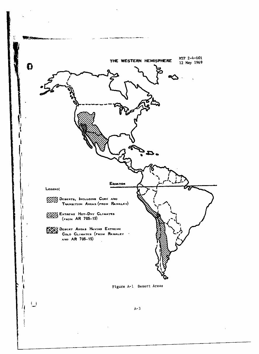
THE WESTERN HEMISPHERE IAT -- 0
¶117
DEsERTS, INCLUDING CORE AND
TRANSITION AREAS (FROM RAMALEY)
EXTREME HOT-DRY CLIMATEts
(FROM AR 705-15)
I ~ DESERT AREAS HAVING EXTREMECOD CLIMATES (FROM RAMALEY
AND AR 705-15')
II
Figure A-I Desert Areas
A- 3

-WrP 2-4-00112 May 1969
THE EASTERN HEMISPHERE
%I
4comb4
Figure A-l.a Desert Areas
A-4

MTP 2-4-001
3 12 May 1969
FAU1lT BASED FoLo BASED
Topaw.NYTopogta pmity
I ~wU
0 >i
'A-
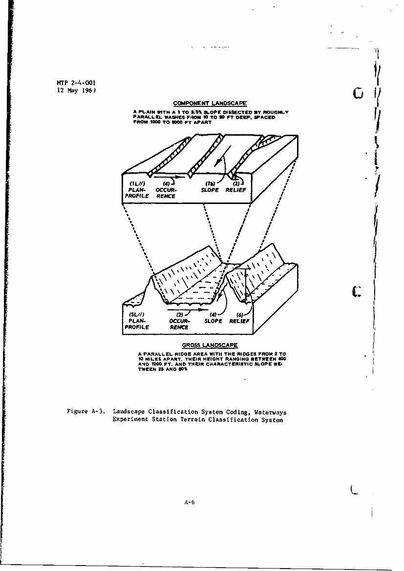
,i
MTP 2-4-00112 May 1969)•"
COMPONENT LANDSCAPE
A PLAIN WITH A I TO &I% SLOPE DISSECTED BY ROUGHLYPARALLEL WASHES FRIOM 10 TO 10 FT DEEP, SPACEDFROM U00 TO 9000 FT APART
(21 '1(IL//) ( 2)1 - (4)
PLAN- OCCUR- SLOPE RELIEF I
PROFILE RENCE
e
V MIE APAR .THI EGTRNIN BEWE,0
I LAN0 oWW uFT .ADTERCAATRSI SLOPE
TWEEN 25 AND 90%
Figure A-3. Landscape Classification System Coding, WaterwaysEx~perimnent Station Terrain Classification System
A-6

MTP 2-4-001S•.-)12 May 969
CHARACTERISTIC PLAN-PROFILE
The characteristics plan-profile is the most commonly found plan-profile within ." region. It may be either gross or restrictive. A gross plan-.1 profile is one that can be subdivided into two restrictive component plan-profiles each exhibiting relief of a lower order than the gross plan-profile.Random sampling with circles 35 miles in diameter is bsed in determining thegross profile. Random sampli.ig with circles I mile in diameter is used todetermine the restrictive plan-proZile. Local relief of less than 10 feet isnot considered. PLEGEND_
-Highs are - Non-linear Linear and Non-linear Linear andand Random Random and Parallel Parallel
Schematic
__________ Profile 0 0
<40% of area 3 ..... / 3L'I
>60% of area p 4 i 41, 4,/ 4L ,,.4 ininr
40-60% of area 0 M EL MW=19
<40% of area a 6..6L - 6"
No pronounced Thighs or lows . -u_
REPRESENTATIVE PLAN- PROFILE
Each of the following block diag-ams illustrates a landscaperepresent:ative of a specific plan-profile type. It should be emphasizedthat, within the defined l~mits of each type, a wide variety of landscapeconfigurations re possible.
I a 3 4
1 6 6Figure A-4 CHA1ACTERISTIC PLAN-PROFILE CODINGS
A-7

MTP 2-4-00112 May 1969 0
4 no 1
00
""-4to 000O
.IN.
,,- QU ! * aI sX JI
,- -*4 010 -'I
00
o o, o.I , 33 , ,,
W O!
.4 O 4.0 U I I X.'t I 3IU%0
ca 131
.4X
14
to Q
0 00-
a• 41 0'
u -4
0,,,-.4 3 I 3
w *- 0 0 11 1
9 9 "
- 0 0c4 N * X I I I
xN D S I XI I I
4~ 0)4
"0 r4ý - C14 glassL %
44 i