Embed Size (px)
Citation preview

ROTARY TILLERSO P E R A T O R ’ S M A N U A L
Cod. F07010182 / Rev. 01 (2006-01)
RT 1170
RT 1080 E
RT 1280
RT 1207
RT 1208
RT 1270
RT 1180

Technical specificationTechnical specification ................................. 4Technical specification - Hitch ...................... 6
Safety signsSafety-Alert simbol ....................................... 7Identification machine .................................. 7Machine safety labels .................................. 7
Machine safety labels and positionsMachine safety labels and positions ............ 8
Preparing the vehiclePreparing the tractor .................................... 10Park vehicle safety ....................................... 10Stay clear of rotating drivelines .................... 10
InstallingInstalling tiller on tractor ............................... 10PTO shaft ..................................................... 12PTO shaft with clutch ................................... 13Quick Coupler (optional) .............................. 14Park vehicle safety ....................................... 14Stay clear of rotating drivelines .................... 14
RemovingRemoving tiller ............................................. 15Removing tiller with Quick Coupler .............. 15
OperatingOperate safely.............................................. 16Wear appropriate clothing ............................ 17Stay clear of rotating drivelines .................... 17Raising parking stand .................................. 17Lowering parking stand ................................ 17Levelling attachments (side-to-side) ............ 17Levelling tiller (front-to-rear) ......................... 18Adjusting skid shoes .................................... 18Adjusting levelling board .............................. 18Change speed.............................................. 19Tilling tips ..................................................... 20
TABLE OF CONTENTS
During tilling ................................................. 20Replacement parts ....................................... 20
Service Machine SafelyPractice safe maintenance........................... 21Wear appropriate clothing ............................ 21Stay clear of rotating drivelines .................... 21
Service lubricationService lubrication........................................ 22Every 8 work hours ...................................... 22Every 50 work hours .................................... 22Every 400 work hours .................................. 22Every 1000 work hours ................................ 22Greasing and lubricant points ...................... 23Lubricants .................................................... 23Screw tighteening torques ........................... 23
ServiceChain stretcher............................................. 24Service intervals........................................... 24Replacing tines ............................................ 24Tines ............................................................ 24
TroubleshootingUsing troubleshooting chart ......................... 25
Storing machineStoring tiller .................................................. 26Removing tiller from storage ........................ 26
Assembly / Spare partsRT 1170-1080 E-1270-1180-1280-1207-1208 27Lift hook assembly procedur ........................ 29Installing driveline on tiller ............................ 29Spare parts .................................................. 29
WarrantyWarranty ...................................................... 30Warranty for replacement parts ................... 31

TO THE DEALER:Assembly and proper installation of this product is the responsibility of the Frontier dealer. Read manualinstruction and safety rules. Make sure all items on the Dealer’s Pre-Delivery Check List in the Operator’sManual are completed before releasing equipment to the owner.
The dealer must complete the Warranty Registration, located on the Frontier website. Warranty claimswill be denied if the Warranty Registration has not been completed.
TO THE OWNER:Read this manual before operating your frontier equipment. The information presented will prepare youto do a better and a safer job. Keep this manual handy for ready reference. Require all operators to readthis manual carefully and become acquainted with all the adjustment and operating procedures beforeattempting to operate. Replacement manuals can be obtained from your selling dealer.
The equipment you have purchased has been carefully enginereed and manufactured to providedependable and satisfactory use. Like all mechanical products, it will require cleaning and upkeep.Lubricate the unit as specified. Observe all safety information in this manual and safety decals on theequipment.
For service, your authorized Frontier dealer has trained mechanics, genuine Frontier service parts, andthe necessary tools and equipment to handle all your needs.
Use only genuine Frontier service parts.Substitute parts will void the warranty and may not meet standardsrequired for safe and satisfactory operation. Record the model number and serial number of your equipmentin the spaces provided:
Model: Date of Purchase
Serial Number: (see Safety Decal section for location)
This Safety-Alert Simbol indicates a hazard and meansATTENTION! BECOME ALERT! YOUR SAFETY IS INVOLVED!
Indicates an imminently hazardous situation that, if not avoided,will result in death or serious injury.
Indicates a potentially hazardous situation that, if not avoided, couldresult in death or serious injury, and includes hazards that areexposed when guards are removed.
Indicates a potentially hazardous situation that, if not avoided, mayresult in minor or moderate injury.
Indicates that a failure to observe can cause damage to equipment.
Indicates helpful information.
Provide this information to your dealer to obtain correct repair parts.
Throghout this manual, the term IMPORTANT is used to indicate that failure to observe can causedamage to equipment. The terms CAUTION, WARNING and DANGER are used in conjunction with theSafety-Alert Symbol, (a triangle with an esclamation mark), to indicate the degree of hazard for items ofpersonal safety.
WARNING
CAUTION
IMPORTANT
NOTE
DANGER
Cod. F07010182 / Rev. 01 (2006-01)
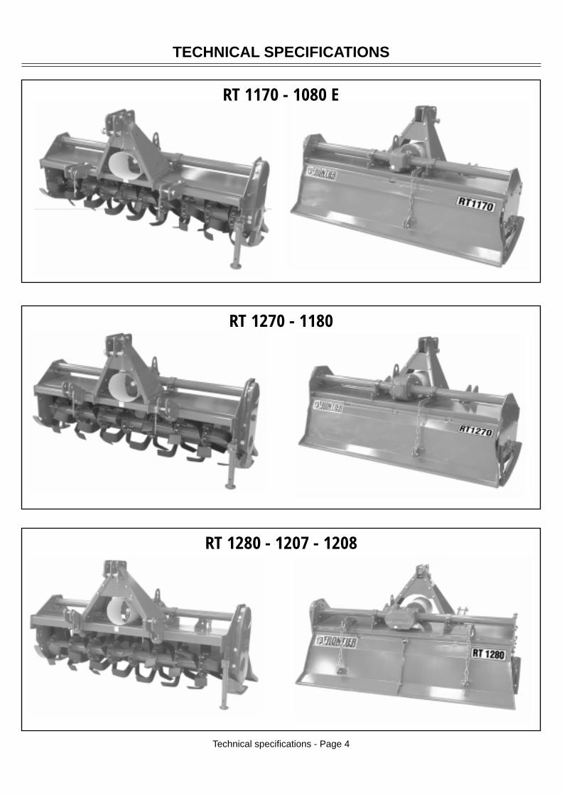
RT 1280 - 1207 - 1208
TECHNICAL SPECIFICATIONS
Technical specifications - Page 4
RT 1170 - 1080 E
RT 1270 - 1180

Model Work/width Tractor HP Tractor HP Weight Side PTO Speeds Input Hitch Tines Rotor Rotorinches min max lbs. Drive shaft gear box speed STD blades flanges
Chain Slip Cat. “II”RT 1170 73 45 60 761 ASA Clutch Single 540 Quick “C” 6 9
100 couplerChain Slip Cat. “II”
RT 1080 E 81 50 60 810 ASA Clutch Single 540 Quick “C” 6 10100 coupler
TECHNICAL SPECIFICATIONS
Technical specifications - Page 5
Model Work/width Tractor HP Tractor HP Weight Side PTO Speeds Input Hitch Tines Rotor Rotorinches min max lbs. Drive shaft gear box speed STD blades flanges
Slip Cat. “II”RT 1270 73 30-70 80 968 Gear Clutch Single 540 Quick “L” 6 7
couplerSlip Cat. “II”
RT 1180 83 30-70 80 1056 Gear Clutch Single 540 Quick “C” 6 8coupler
Model Work/width Tractor HP Tractor HP Weight Side PTO Speeds Input Hitch Tines Rotor Rotorinches min max lbs. Drive shaft gear box speed STD blades flanges
Cat. ”II”RT 1280 83 30-70 80 1397 Gear Slip Multi 540 Quick “L” 6 8
Clutch couplerCat. ”II”
RT 1207 93 40-80 100 1496 Gear Slip Multi 540 Quick “L” 6 9Clutch coupler
Cat. ”II”RT 1208 103 40-80 100 1584 Gear Slip Multi 540 Quick “L” 6 10
Clutch coupler
RT 1170 - 1080 E
RT 1280 - 1207 - 1208
RT 1270 - 1180

TECHNICAL SPECIFICATIONS - HITCH
RT 1170 - 1080 E: Cat. «II» Standard and Quick Coupler
Technical specifications - Hitch - Page 6
Cat. «II» Standard bushings Ø = 28 (inch 1.1)Cat. «II» Quick Coupler bushings Ø = 36,5 (inch 1.44)
RT 1270 - 1180: Cat. «II» Standard and Quick Coupler
RT 1280 - 1207 - 1208: Cat. «II» Standard and Quick Coupler
=
=
mm 823 - inch 32,4 cat. 2 Ø
Ø
=
=
mm 823 - inch 32,4 cat. 2
mm 823 - inch 32,4 cat. 2
=
=
Cat. II Std pin Ø mm 25 (inch 0.984)
Cat. II Quick Coupler pin Ø mm 32 (inch 1.26)
Without bushings: Cat. «II» Standard
With bushings: Cat. «II» Quick Coupler
Cat. II Std pin Ø mm 25 (inch 0.984)
Cat. II Quick Coupler pin Ø mm 32 (inch 1.26)
Without bushings: Cat. «II» StandardWith bushings: Cat. «II» Quick Coupler
Cat. II Std pin Ø mm 25 (inch 0.984)
Cat. II Quick Coupler pin Ø mm 32 (inch 1.26)

SAFETY SIGNS
Safety Signs - Page 7
Safety-alert symbolRead and recognize safety information.Be alert to the potential for personal injury when you see this safety-alert symbol.
On your machine safety labels, the words DANGER, WARNING, and CAUTION are used with safety-alert symbol.DANGER identifies the most serious hazards. In this manual, the word CAUTION and this symbol callattention to safety messages.
Identification machineIdentification plate machine
Machine safety labels
1) WARNING: AVOID INJURY FROM ROTATING KNIVES:• Keep hands, feet and clothing away.
2) WARNING: AVOID INJURY FROM PTO:• Keep all shields in place. Keep hands, feet and clothing away.• Operate only with 540 RPM.
3) CAUTION: AVOID INJURY• Read Operator’s Manual• Ballast power unit per operator’s manual• Know location and function of controls• Keep all shields in place• Stay clear of power driven parts• Never carry riders• Keep people and pets a safe distance away from machineBEFORE DISMOUNTING OR SERVICING• Shut off engine and remove key• Lock brake for park• Lower or block up machine
4) DANGER: ROTATING DRIVELINE - CONTACT CAN CAUSE DEATH - KEEP AWAY! - DO NOTOPERATE WITHOUT:• All driveline, tractor and equipment shields in place• Drivelines securely attached at both ends• Drivelines shields that turn freely on driveline.
5) DANGER: SHIELD MISSING DO NOT OPERATEPicture Note: Separate telescoping driveshaft members to locate safety label. Label attached to outer profiletube.

1
3
2
54
MACHINE SAFETY LABELS AND POSITIONS
Safety Signs - Page 8
4
5
RT 1170 - 1080 E
RT 1280 - 1207 - 1208
RT 1270 - 1180
32
1
1
32
1
1
32
1
1

MACHINE SAFETY LABELS AND POSITIONS
MAXKg...
6
GREASE
7
OIL
LEVEL
8
OIL
9
OIL
10
540MAX
11
RT 1170 - 1080 E
RT 1270 - 1180
6) Coupling point for lifting (indicating the maximun capacity)7) Greasing point8) Oil level plug9) Oil drain plug
10) Oil fill plug11) Number of revolutions of power takeoff12) Warning, slow machine13) Red strip (only for model: 1207 and 1208)14) Amber strip (only for model: 1207 and 1208)
Safety Signs - Page 9
12
7
10
8
9
6
11
7
8
9
10
12
11
10
8
9
6
7
8
9
10
12
11
10
8
9
6
12
10
8
9
13
14
1234567890123456789012345123456789012345678901234512345678901234567890123451234567890123456789012345123456789012345678901234512345678901234567890123451234567890123456789012345
12345678901234561234567890123456123456789012345612345678901234561234567890123456
14
1413
13

Preparing the tractor
CAUTION: Avoid injury. Proper ballastings is required for safe operation of your tiller
IMPORTANT: Refer to the tractor operator manual for proper ballasting information and tire inflation
• A 540 rpm PTO• Refer to the tractor operator manual for correct ballasting and tire pressure, depending on installed
equipment.
PREPARING THE VEHICLE
Preparing the vehicle - Page 10
A
Park vehicle safety• Stop vehicle on a lever surface, not on a slope.• Disengage PTO.• Engage the park brake.• STOP the engine.• Remove the key.• Before you leave the operator’s seat, wait for engine
and all moving parts to STOP.
Stay clear of rotating drivelinesEntanglement in rotating driveline can cause seriousinjury or death:
• Wear close fitting clothing.• STOP the engine and be sure PTO driveline is stopped
before getting near it.
Installing tiller on tactor1. Back tractor into position and align draft links (A) with
draft link brackets on tiller using tractor rockshaftcontrol.
CAUTION: Before you work around hitch:• STOP engine.• LOCK park brake.• FIRMLY block tiller on horizontal surface.
Locate driller pin in holes (B).RT 1170 - 1080 E model:
2. Insert bushings (D) in each draft links than fasteneach draft link to draft link brackets with drilled pinsand quiklock pins (C).
For cat. «II» Standard bushings Ø = 28 (inch 1.102)For cat. «II» Quick Coupler bushings Ø = 36,5 (inch 1.437)
CB
A
D

Locate driller pin in top lift brackets holes (B).
RT 1270-1180 model (Cat. «II» Std.):2. Fasten each draft link (A) to draft link brackets with
drilled pins and quiklock pins (C).
Locate driller pin in lower lift brackets holes (E).
RT 1270-1180 model (Cat. «II» Quick Coupler):2. Insert bushings (D) in each draft links (A) than fasten
each draft link to draft link brackets with drilled pinsand quiklock pins (C).
Locate driller pin in holes (B).RT 1280-1207-1208 model (Cat. «II» Std.):
2. Fasten each draft link (A) to draft link brackets withdrilled pins and quiklock pins (C).
RT 1280-1207-1208 model (Cat. «II» QuickCoupler):
2. Insert bushings (D) in each draft links (A) than fasteneach draft link to draft link brackets with drilled pinsand quiklock pins (C).
Locate driller pin in top holes (D)RT 1280-1207-1208 model (Cat. «II» Std.):
3. Install center link (F) on tiller and fasten with drilledpin and quiklock pin (E).
Locate driller pin in top holes (G)RT 1280-1207-1208 model (Cat. «II» QuickCoupler):
3. Install center link (F) on tiller and fasten with drilledpin and quiklock pin (E).
INSTALLING
Installing - Page 11
F
C
A
C
B
A
G
E
D
B
E
D
D
A
B
INSTALLING
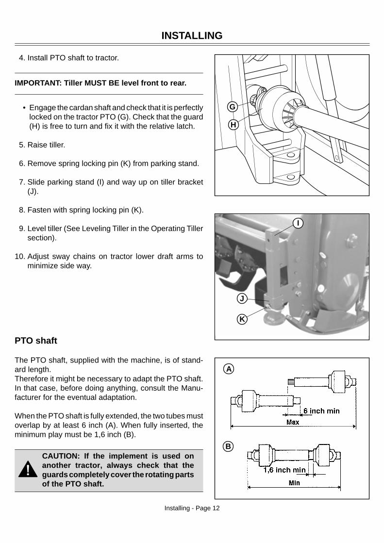
4. Install PTO shaft to tractor.
IMPORTANT: Tiller MUST BE level front to rear.
• Engage the cardan shaft and check that it is perfectlylocked on the tractor PTO (G). Check that the guard(H) is free to turn and fix it with the relative latch.
5. Raise tiller.
6. Remove spring locking pin (K) from parking stand.
7. Slide parking stand (I) and way up on tiller bracket(J).
8. Fasten with spring locking pin (K).
9. Level tiller (See Leveling Tiller in the Operating Tillersection).
10. Adjust sway chains on tractor lower draft arms tominimize side way.
PTO shaft
The PTO shaft, supplied with the machine, is of stand-ard length.Therefore it might be necessary to adapt the PTO shaft.In that case, before doing anything, consult the Manu-facturer for the eventual adaptation.
When the PTO shaft is fully extended, the two tubes mustoverlap by at least 6 inch (A). When fully inserted, theminimum play must be 1,6 inch (B).
CAUTION: If the implement is used onanother tractor, always check that theguards completely cover the rotating partsof the PTO shaft.
Installing - Page 12
H
K
J
I
G

D
PTO shaft with clutchThe PTO shaft can be equipped with safety clutch toprotect the transmission components of the machinefrom stress and/or excessive overloads.
The tilt of the PTO shaft must not exceed 10 degrees.
The clutch is already pre-adjusted for average stress. If itslips too easily (and overheats), it will be necessary toevenly tighten all the nuts (D) that retain the springs.The clutch disks must be changed if the clutch still slipsafter all the nuts have been tightened.If the clutch does not slip, evenly unscrew all the springfixing nuts (D). Unscrew one turn at a time and check theclutch after having worked about 300 meters. Repeat theoperation if necessary, remembering to unscrew one turnat a time. If the clutch maintains a temperature of about40-50 (104-122 °F) degrees during work, this means thatit has been correctly regulated.
IMPORTANT: Never fully tighten the nuts. This wouldvoid the function of the springs and, subsequently, ofthe clutch, thus damaging the transmission compo-nents.
NOTE: This inspection must be performed at thebeginning of each new season.
INSTALLING
Installing - Page 13

Installing - Page 14
A
C
B
C
INSTALLING
E
Quick Coupler (optional)
1) Install hitch Quick Coupler (A) on the tractor (seetractor operator manual).
2) Stop vehicle on a level surface, not on a slope, thenmoving back to the tractor until the Quick Coupler(A) is range with the (B) and (C) hitch points.
3) Raise the Quick Coupler (A) and make sure that tiller’shitch is in the right position (E).
CAUTION: Before you work around hitch:• STOP engine.• LOCK park brake.• FIRMLY block tiller on horizontal surface.
Park vehicle safely• Stop vehicle on a level surface, not on a slope.• Disengage PTO.• Engage the park brake.• STOP the engine.• Remove the key.• Before you leave the operator’s seat, wait for engine and all moving parts to STOP.
Stay clear of rotating drivelinesEntanglement in rotating driveline can cause serious injury or death:• Wear close fitting clothing.• STOP the engine and be sure PTO driveline is stopped before getting near it.
D
D
REMOVING
Removing - Page 15
A
C
B
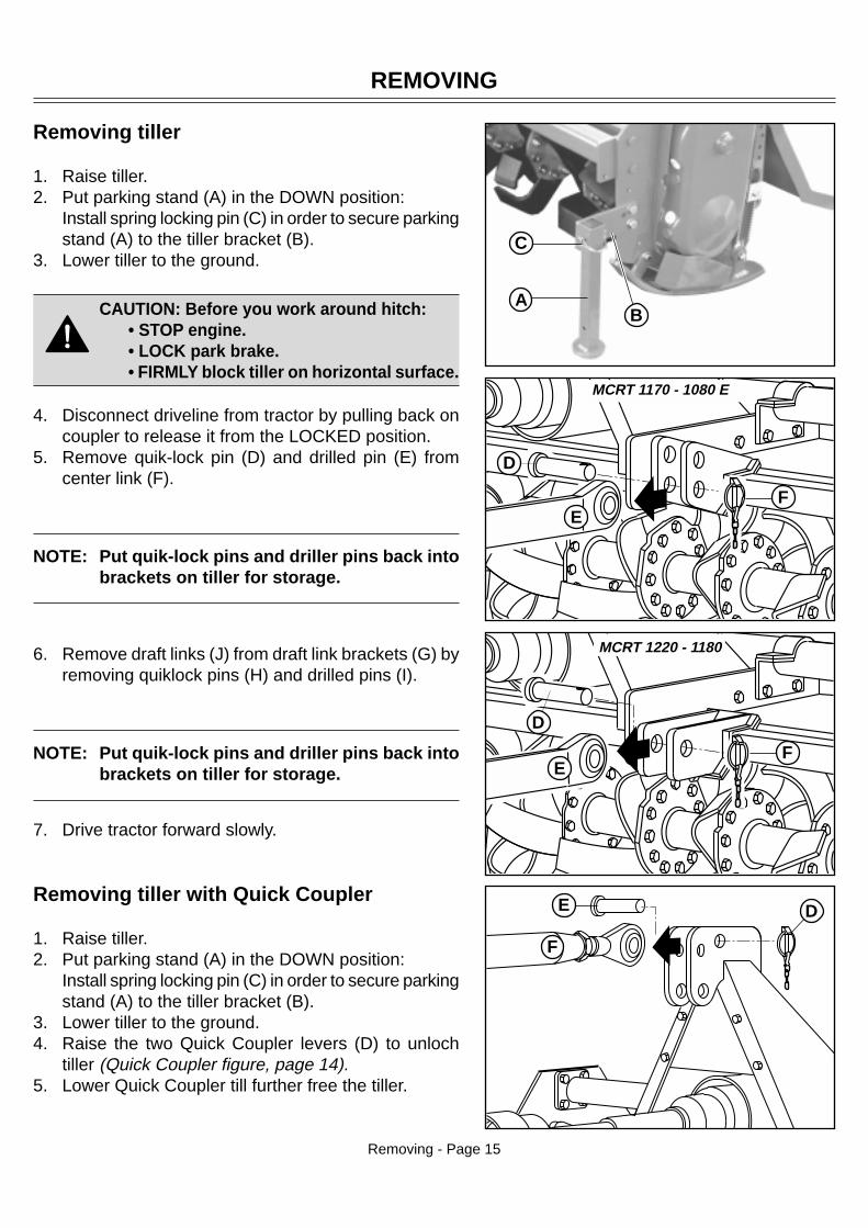
Removing tiller
1. Raise tiller.2. Put parking stand (A) in the DOWN position:
Install spring locking pin (C) in order to secure parkingstand (A) to the tiller bracket (B).
3. Lower tiller to the ground.
CAUTION: Before you work around hitch:• STOP engine.• LOCK park brake.• FIRMLY block tiller on horizontal surface.
4. Disconnect driveline from tractor by pulling back oncoupler to release it from the LOCKED position.
5. Remove quik-lock pin (D) and drilled pin (E) fromcenter link (F).
NOTE: Put quik-lock pins and driller pins back intobrackets on tiller for storage.
6. Remove draft links (J) from draft link brackets (G) byremoving quiklock pins (H) and drilled pins (I).
NOTE: Put quik-lock pins and driller pins back intobrackets on tiller for storage.
7. Drive tractor forward slowly.
Removing tiller with Quick Coupler
1. Raise tiller.2. Put parking stand (A) in the DOWN position:
Install spring locking pin (C) in order to secure parkingstand (A) to the tiller bracket (B).
3. Lower tiller to the ground.4. Raise the two Quick Coupler levers (D) to unloch
tiller (Quick Coupler figure, page 14).5. Lower Quick Coupler till further free the tiller.
E
FE
F
D
MCRT 1170 - 1080 E
MCRT 1220 - 1180
D
FE
D

123456789012345678901234567890123456789012345678901234567890123456789012345678901234567890123456789012345678901234567890123456789012345678901234567890123456789012345678901234567890123456789012345678901234567890123456789012345678901234567890123456789012345678901234567890123456789012345678901234567890123456789012345678901234567890123456789012345678901234567890123456789012345678901234567890123456789012345678901234567890123456789012345678901234567890123456789012345678901234567890123456789012345678901234567890123456789012345678901234567890123456789012345678901234567890123456789012345678901234567890123456789012345678901234567890123456789012345678901234567890123456789012345678901234567890123456789012345678901234567890123456789012345678901234567890123456789012345678901234567890
OPERATING
Operating - Page 16
• Clear work area of objects that you do not want tilledinto the ground or that might damage the tiller. Con-sider the tilling area and set up a safe tilling pattern.Do not till under condition in which traction or stabilityis doubtful. Keep people and pets out of the work area.Stop machine if anyone enters the area.
• If you hit an object, stop the machine and inspect it.Make repairs before you operate. Keep machine prop-erly maintained and in good working order.
• DO NOT leave machine unattended when it is run-ning.
• Only operate during daylight or with good artificial light.• DO NOT let anyone, ESPECIALLY CHILDREN, ride
on machine or vehicle. Riders are subject to injury suchas being thrown off. Riders may also obstruct theoperator’s view, resulting in the machine being oper-ated in an unsafe manner.
• DO NOT let children or an untrained person operatemachine.
• DO NOT wear radio or music headphones while oper-ating the machine. Safe operation requires your fullattention.
• DO NOT operate the tractor and tiller when you aretired or ill.
Operate safely• Protect your hands when you inspect or unplug the tiller. You may need gloves or tools, such as a
screwdriver or scraper. Be sure hardware is tight. Repair or replace damaged, badly worn, or missingparts. Be sure guards and shields are in good condition and fastened in place. Make any necessaryadjustments before you operate.
It is absolutely forbidden to stand between the tractor and the implement when maneuveringthe lift control from the outside.

Raising parking stand1. Remove spring locking pin (C).2. Slide parking stand (A) and way up on tiller bracket
(B).3. Fasten with spring locking pin (C).
Lowering parking stand1. Remove spring locking pin (C).2. Slide parking stand (A) and put down on tiller bracket (B).3. Install spring locking pin in order to secure parking
stand to the tiller bracket.4. Fasten with spring locking pin (C).
Leveling attachments (side-to-side)1. Start the engine. Raise the tiller.2. Stop the engine. Lock the park brake.
CAUTION: DO NOT work under a raisedtiller unless it is safely supported.
OPERATING
Operating - Page 17
C
B
A
A
C
B
CAUTION: Before you work around hitch:• STOP engine.• LOCK park brake.• FIRMLY block tiller on horizontal surface.
Wear appropriate clothing• Wear close fitting clothing and safely equipment appropriate for the job.• Loud noise can cause impairment or loss of hearing, wear a suitable protective device such as earplugs.
Stay clear of rotating drivelinesEntanglement in rotating driveline can cause serious injury or death:• Wear close fitting clothing• Stop the engine and be sure PTO drivelines is stopped before getting near it.

OPERATING
Operating - Page 18
Leveling tiller (front-to-rear)1.Start the engine.2.Lower the tiller to 25 mm (1 in.) off the ground.3.Stop the engine.4.Make sure the top of the tiller is LEVEL, or PARALLEL
with the ground, front-to-rear.5.Adjust level, if necessary. To adjust level:
a. Start the engine.b. Lower the tiller to the ground.c. Stop the engine.d. Loosen jam nut (A).
• Shorten the center link (B) to lower the front of thetiller.
• Lengthen the center link (B) to raise the front ofthe tiller.
e. Tighten jam nut.
CAUTION: Before you work around hitch:• STOP engine.• LOCK park brake.• FIRMLY block tiller on horizontal surface.
Adjusting skid shoes
Before adjusting skid shoes lift tiller, place tiller on top oftwo wooden blocks underneath tiller rotor (see figure).
1. Raise tiller.2. Place wooden blocks.3. Lower tiller on wooden blocks.4. Loosen pivot bolt (A) and (D).5. Loosen adjusting bolt (B) and lock nut.6. Adjust skid shoe (C) to desired position.7. Tighten bolts (A), (B) and (D).
NOTE: Adjust both skid shoes to same depth.
6. Repeat above steps for the other skid shoe.
Adjusting leveling board
1. Install chain (A) in bracket (B).2. Lower leveling board to top of ground (C):
• Tilled soil (D) will be fine and level.• Tractor speed will determine size of clods (E).
A D
C
B
A
B
B
A

Change speed
Rotary harrows are equipped with a gearshift with onepair of gears. A variety of rotation speeds of the rotorcan be obtained so that the needs of the operator canbe better met.It is very useful for land which is uneven in that it makesrotary hoeing easy and at the same time allows the trac-tor to be maintained at a constant speed.To change tiller speed you must:1) Unscrew its bolds and remove the rear cover of the
gearbox.
CAUTION: Watch out: oil will come out.
2) It is advisable to bend the rotary cultivator forwards.3) Pull the gears off their shafts and invert the position
of their seats.
The name-plate on the cover gives the number of teethof the gear pair originally installed by the Manufacturer,furthermore, as on page 4 of this handbook, there arethe speeds pertainig to the pairs of gears monuted onpurchase, plus of the spare pairs.Each rotary cultivator with gear change has a label whichindicates the gear couple mounted as first equipment.The label is attached to the third-point.
OPERATING
Operating - Page 19
B
C
E
DE
C
CAUTION: Before you work around hitch:• STOP engine.• LOCK park brake.• FIRMLY block tiller on horizontal surface.
3. Raise leveling board (C):• Tilled soil (D) will be coarse and rough.• Tractor speed will determine size of clods (E).

CAUTION: Be very careful and ensure to use the right gears, since some gear pairs can-not be inverted, and gears from different pairs cannot be interchanged. Strictly complywhith the pairs of gears indicated, in the chart on page 4.
Optimum tilling depends on two factors:1) Forward speed of the tractor.2) Rotation speed of the blade-carrying rotor.The faster the rotor rotates, the more chopped up the soil will be.
Operating - Page 20
Tilling tipsBefore You till:• Pick up rocks and foreign objects.• Mow tall weeds and grass to keep them from wrapping around tines or tine shaft.• Check tines. Loose, bent, broken, or missing tines reduce operating efficiency. If necessary, replace
tines.Test the soil by squeezing it in your hand. If soil forms a ball, it is too wet to till. If soil does not compresseasily or falls apart, it is ready to till.DO NOT till when soil is wet. Wet soil will stick to the tines and tine shaft. Wet soil will also dry out andbecome hard, making it hard to work with during the growing season.
During tilling
CAUTION: Never lower tiller into the ground while the tractor is turning.
• DO NOT back up or make sharp turn with tiller in ground.• Move PTO switch lever to ON when tiller is out of the ground. Move tractor forward and lower tiller into
the ground.• When you till hard ground or sod, till at a shallow depth on first pass. Increase depth on each pass.• When tilling on a hillside:
- Work up the the slope, if possible.- If lateral work cannot be avoided, work from the top to the bottom in order to limit any terracing effect.
Replacement partsSee Service Dealer for original parts.PART NUMBERS MAY CHANGE, use part numbers listed at the end of this manual when you order. If anumber changes, your dealer will have the latest number.
WHEN YOU ORDER PARTS, your Frontier Equipment dealer needs your machine serial number. This isthe number you have recorded in the INTRODUCTION section in the front of this manual.
OPERATING

SERVICE MACHINE SAFELY
Service Machine Safely - Page 21
Practice safe maintenance• Understand service procedure before doing work. Keep area clean and dry.
• Never lubricate, service, or adjust machine while it is moving. Keep safety devices in place and inworking condition. Keep hardware tight.
• To prevent from getting caught, keep hands, feet, clothing, jewelry, and long hair away from any movingparts.
• Before servicing machine, lower it to the ground. Disengage all power and stop the vehicle engine. Lockvehicle park brake and remove the key.
• Securely support any machine elements that must be raised for maintenance.• Keep all parts in good condition and properly installed. Fix damage immediately. Replace worn or broken
parts. Remove any buildup of grease, oil, or debris.• Unauthorized modifications to the machine may impair its function and safety.
Wear appropriate clothing
• Wear close fitting clothing and safely equipment appropriate for the job.• Loud noise can cause impairment or loss of earing, wear a suitable protective device such as earplugs.• Do not wear radio or music headphones while servicing the machine. Safe servicing requires your full
attention.
Stay clear of rotating drivelines
Entanglement in rotating driveline can cause serious injury or death:• Stop the engine and be sure PTO drivelines is stopped before getting near it.
Service lubrication
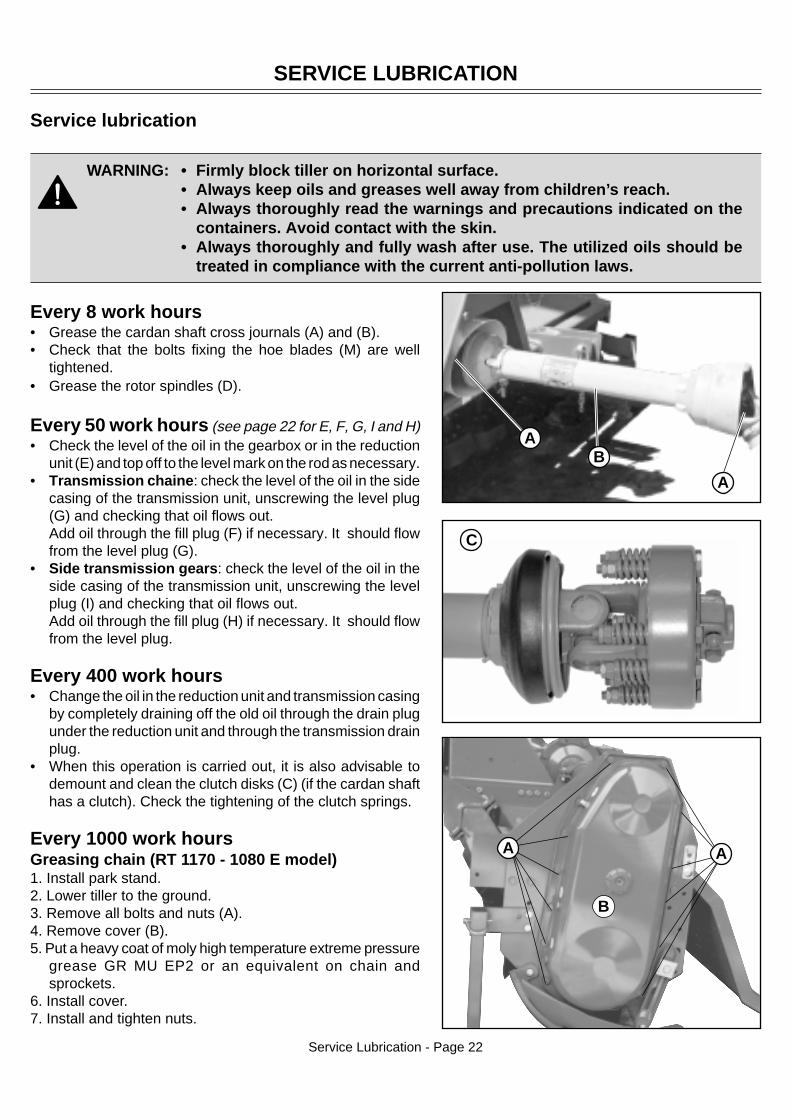
WARNING: • Firmly block tiller on horizontal surface.• Always keep oils and greases well away from children’s reach.• Always thoroughly read the warnings and precautions indicated on the
containers. Avoid contact with the skin.• Always thoroughly and fully wash after use. The utilized oils should be
treated in compliance with the current anti-pollution laws.
AB
A
Every 8 work hours• Grease the cardan shaft cross journals (A) and (B).• Check that the bolts fixing the hoe blades (M) are well
tightened.• Grease the rotor spindles (D).
Every 50 work hours (see page 22 for E, F, G, I and H)• Check the level of the oil in the gearbox or in the reduction
unit (E) and top off to the level mark on the rod as necessary.• Transmission chaine: check the level of the oil in the side
casing of the transmission unit, unscrewing the level plug(G) and checking that oil flows out.Add oil through the fill plug (F) if necessary. It should flowfrom the level plug (G).
• Side transmission gears: check the level of the oil in theside casing of the transmission unit, unscrewing the levelplug (I) and checking that oil flows out.Add oil through the fill plug (H) if necessary. It should flowfrom the level plug.
Every 400 work hours• Change the oil in the reduction unit and transmission casing
by completely draining off the old oil through the drain plugunder the reduction unit and through the transmission drainplug.
• When this operation is carried out, it is also advisable todemount and clean the clutch disks (C) (if the cardan shafthas a clutch). Check the tightening of the clutch springs.
Every 1000 work hoursGreasing chain (RT 1170 - 1080 E model)1. Install park stand.2. Lower tiller to the ground.3. Remove all bolts and nuts (A).4. Remove cover (B).5. Put a heavy coat of moly high temperature extreme pressure
grease GR MU EP2 or an equivalent on chain andsprockets.
6. Install cover.7. Install and tighten nuts.
C
SERVICE LUBRICATION
Service Lubrication - Page 22
B
A A

SERVICE LUBRICATION
Service Lubrication - Page 23
D
➤
Greasing and lubricant points
D) Rotor spindle lubricatorE) Reduction unit oil plugF) Transmission oil fill plugG) Transmission oil drain plugH) Transmission oil fill plugI) Transmission oil level plugL) Transmission oil drain plugM) Hoe blades fixing bolts
Lubricants• It is advisable to use SAE 85W/140 OIL or equivalent for the reduction unit (or gear box) and side
transmission.• It is advisable to use GR MU EP 2 GREASE or equivalent for all greasing points.
M
E
I
H
L
F
G
Chain transmissionGear transmission
1170 1270 - 1180OIL QUANTITY: lt (US gal.)
1080 E 1280 - 1207 - 1208
Reduction unit oil (E) 1 (0.26) 1,5 (0.39)
Transmission oil fill chain (F) 1,4 (0.36) -
Transmission oil fill gears (H) - 2 (0.53)
Fine pitch screws CLASS
6.6 8.8 10.9 12.9
M8 x 1 15 (11) 26 (19) 36 (26.5) 44 (32.5)
M10 x 1.25 30 (22) 52 (38) 74 (54) 88 (65)
M12 x 1.25 51 (37.5) 91 (67) 127 (94) 153 (113)
M14 x 1.5 81 (60) 143 (105) 201 (148) 241 (178)
M16 x 1.5 120 (88) 214 (158) 301 (222) 361 (266)
M18 x 1.5 173 (127) 308 (227) 433 (319) 520 (384)
M20 x 1.5 242 (178) 431 (318) 606 (447) 727 (536)
M22 x 1.5 321 (237) 571 (421) 803 (592) 964 (711)
M24 x 2 411 (303) 731 (539) 1028 (758) 1234 (910)
M27 x 2 601 (443) 1070 (790) 1504 (1110) 1806 (1333)
M30 x 2 832 (614) 1480 (1090) 2081 (1535) 2498 (1843)
Bolts tightening torques - settings given in Nm (lb-ft)

Chain stretcher (RT 1170 - 1080 E model)A special mechanical chain stretcher regulates the tension of the drive chain (A). If there is too much play,then you must loosen lock nut (B) and tighten screw (C) as much as necessary. Then retighten lok nut whichlocks the adjustment screw into place.
Service intervalsEvery 50 working hours:• Tighten mast brackets bolts.• Tighten skid shoe bolts.
Replacing tines
CAUTION: To prevent injuri: Wear heavy gloves when replacing tines.
To get the best performance from your tiller:• Replace badly bent, worn, or broken tines immediatly.• Replace worn or broken hardware (see your Frontier dealer for correct hardware).• MAKE SURE to replace tines on ONE spindle at time to keep spiral tine pattern.• Tine cutting edge MUST BE facing forward in direction of tine rotation.
CAUTION: Make sure you block tiller before doing any service on the tiller.• STOP engine. • LOCK park brake. • FIRMLY block tiller on horizontal surface.
Tines can be changed with the tiller mounted on tractor. Make sure you block the tiller before doing anyservice on the tiller.
SERVICE
Service - Page 24
B
C
A
Front
Rear
A
B
TinesBefore replacing tines make sure the tiller is firmlyblocked.The tines with which the rotary tiller is equipped can worksoils of normal conformation. Check the degree of wearand condition of the tines each day. If the blades shouldaccidentally bend (or break) during work, they must beimmediately replaced.First - Identify tines:Remember to mount the new tine in exactly the sameposition as the old one (A). If several tines must bereplaced, it is advisable to remove and assemble one tineat a time in order to prevent positioning errors.The tillers are normally equipped with 4 blades per flange.Second - Install New Tines:1. Raise tiller with a safe lifting device.1. Put safety stands or blocks under tiller.3. Stand facing rear of tiller and study placement of tines.4. Remove four bolts, lock washers, and nuts (C).
C

TROUBLESHOOTING
Using troubleshooting chart
If you are experiencing a problem that is not listed in this chart, see your Frontier dealer for service.When you have checked all the possible causes listed and you are still experiencing the problem, seeyour Frontier dealer.
IF CHECKEXCESSIVE TINE WEAR Replace loose or bent tine.
Replace tine when worn to a point.TILLER BUMPING ON GROUND Obstacles entangled in tines.
Blades incorrectly mounted with no tine spiral effect.Tines fitted with blunt edge leading.Broken tines.
INSUFFICIENT DEPTH OBTAINED Adjust depth control skids.Insufficient power - use lower tractor speed.Chain cover on hard soil - further passes required.Blades rolling over ground - use lower tractor speed.Adjust depth control on tractor.
TILLED SOIL TOO FINE Raise leveling board.Use a faster tractor ground speed.
TILLED SOIL TOO COARSE Lower leveling board.Use lower tractor speed.Wait until soil is drier.
TINES BALLING UP WITH SOIL Raise leveling board.Decrease tractor speed.Ground too sticky for working.
CUTTING TOO DEEP ON ONE SIDE Tiller not level:• Level tiller.• Adjust depth control skid.
NOT OVERLAPPING Drive closer to last run.Start in center and go around clockwise (tilled soil to the right of the operator.)
NOTE: Make sure to replace tines on ONE spindle at a time to keep spiral tine pattern.
5. Remove left-hand tine (A) and right-hand tine (B).6. Install new tines and fasten with bolts, lock washers, and nuts (removed above).
NOTE: Two bolts go in from each side. Refer to sketch at right.
7. Tighten bolts.
CAUTION: The heads of the bolts fixing the hoe blades in place must be on the side of thehoe blades themselves, while the nut with relative washer must be on the flange side (B).Tighten bolts to 91 Nm.
Troubleshooting - Page 25

STORING MACHINE
Storing Machine - Page 26
Storing tiller
CAUTION: Before you work around hitch:• STOP engine.• LOCK park brake.• FIRMLY block tiller on horizontal surface.
1. Put parking stand in the DOWN position (See Lowering Parking Stand in the Operating Tiller section).
2. Disconnect tiller from tractor (See Removing section).
3. Clean tiller and inside of driveline shield.
4. Repair or replace badly worn or damaged parts.
5. Tighten hardware.
6. Lubricate tiller.
7. Grease chain (See Greasing Chain in the Service - Lubrication section).
8. Store tiller in a dry place on a hard level surface with the parking stand in the LOWERED position.
9. If you store tiller outside, put a waterproof cover on it.
Removing tiller from storage1. Install tiller on the tractor.

RT 1170 - 1270 - 1180 - 1180 E - 1280 - 1207 - 1208
CAUTION: FIRMLY block tiller on horizontal surface.
Installing mast braces (PHASE 1)
1) Install spacer (D), bolt (E) and nut (C) on mast braces (I, M).Do not tighten bolts and nuts at this time.
2) Install front and rear plates (B, H) with bolts and nuts (A, F, L, G) on mast braces.Do not tighten bolts and nuts at this time.
Installing parking stand (PHASE 2, operating 1)
3) Put parking stand (N) and fasten bolts (O) and nuts (P).Tighten lock nuts to the requested tightening torque.
Installing draft link brakets (PHASE 2, operating 2)
NOTE: big holes on brackets should be on bottom (see figure)
4) Put each link brackets (U) and (T) on tool bar and fasten bolts and nuts (V, Z).Do not tighten bolts and nuts at this time.
5) Measure distance between draft, link brackets (U). For the correct measurement of the brackets, cen-tered with gearbox, see the table.
6) Tighten lock bolts (V) and nuts (Z) to secure draft link brackets to tool bar.• Fine Pitch screws: M16 x 1.5• Class: 8.8• Screw tightening torques: 214 Nm (158 lb-ft).
Installing mast braces on tiller (PHASE 2, operating 3)
7) Install mast assembly on tiller frame and tighten. Bolts (R) and nuts (S) to the the requested tighteningtorque.• Fine Pitch screws: M12 x 1.25• Class: 8.8• Bolts tightening torques: 91 Nm (67 lb-ft).
8) Tighten all bolts and nuts (A, L, F and G).9) Tighten bolt and nut (E and C) to the requested tightening torque (in Nm): 214.
ASSEMBLY
Assembly - Page 27

PHASE 1
PHASE 2
C
B
AL
M
F
G
H
I
D E
Q
S
V
U
O
N
P
R
OPERATION 2
OPERATION 3
Assembly - Page 28
ASSEMBLY
Z
T
OPERATION 1

• Means of dispatch. If this item is not indicated, the Manufacturer, while dedicating particular care to thisservice, shall not be held responsible for delays in delivery caused by cases of force majeure.Transport expenses shall always be at the consignee’s charge. The goods travel at the purchaser’s riskand peril even when sold ex destination.
NOTE: The terms right or left indicated in the descriptions refer to the implement when viewed fromthe rear side.
Lift hook assembly procedurfor model RT 1270 - 1180 only1. Remove bolts (A)
2. Untighten bolt (B)
3. Rotate lift hook on vertical position (C)
4. Tighten bolt (A) and bolt (B) to 52 Nm (38 lb-ft) tight-
ening torque.
Installing driveline on tiller
NOTE: Shield removed for clarity ONLY. ALWAYSkeep shield in place.
1. Pull coupler back and slide driveline on driveshaft untilcoupler LOCKS in place.
NOTE: You should hear a clicking sound whendriveline is properly installed.
Spare partsSpare parts should be ordered from your Dealer andshould always include the following indications:
• Type, model and serial number of the machine.These data are punched on the data plate with whichevery implement is equipped.
• Code number of the required spare part. This will befound in the spare parts catalogue.
• Description of the part and required quantity.
• Table number.
ASSEMBLY / SPARE PARTS
Assembly - Page 29
➤
B
C
A

WARRANTY
Warranty - Page 30
MASCHIO S.p.A. warrants this product to be free from defect in material and workmanship. Except as otherwise set forth below, theduration of this Warranty shall be for TWELVE (12) MONTHS COMMENCING ON THE DATE OF DELIVERY OF THE PROD-UCT TO THE ORIGINAL PURCHASER.
Under no circumstances wilI this Warranty apply in the event that the product, in the good faith opinion of MASCHIO, has beensubjected to improper operation, improper maintenance, misuse, or an accident. This Warranty does not apply in the event that theproduct has been materially modified or repaired by someone other than MASCHIO, a MASCHIO authorized dealer or distributor,and/or a MASCHIO authorized service center. This Warranty does not cover normal wear or tear, or normal maintenance items. ThisWarranty also does not cover repairs made with parts other than those obtainable through MASCHIO.
This Warranty is extended solely to the original purchaser of the product. Should the original purchaser sell or otherwise transfer thisproduct to a third party, this Warranty does not transfer to the third party purchaser in any way. There are no third party beneficiariesof this Warranty.
MASCHIO makes no warranty, express or implied, with respect to engines, batteries, tires or other parts or accessories not manufac-tured by MASCHIO. Warranties for these items, if any, are provided separately by their respective manufacturers.
MASCHIO’ obligation under this Warranty is limited to, at MASCHIO’ option, the repair or replacement, free of charge, of theproduct if MASCHIO, in its sole discretion, deems it to be defective or in noncompliance with this Warranty. The product must bereturned to MASCHIO S.p.A. with proof of purchase within thirty (30) days after such defect or noncompliance is discoveredor should have been discovered, routed through the dealer and distributor from whom the purchase was made, transportationcharges prepaid. MASCHIO shall complete such repair or replacement within a reasonable time after MASCHIO receives theproduct.THERE ARE NO OTHER REMEDIES UNDER THIS WARRANTY. THE REMEDY OF REPAIR OR REPLACEMENT IS THESOLE AND EXCLUSIVE REMEDY UNDER THIS WARRANTY.
THERE ARE NO WARRANTIES WHICH EXTEND BEYOND THE DESCRIPTION ON THE FACE OF THIS WARRANTY.MASCHIO S.p.A. MAKES NO OTHER WARRANTY, EXPRESS OR IMPLIED, AND MASCHIO SPECIFICALLY DISCLAIMSANY IMPLIED WARRANTY OF MERCHANTABILITY AND/OR ANY IMPLIED WARRANTY OF FITNESS FOR A PARTICU-LAR PURPOSE.
MASCHIO S.p.A. shall not be liable for any incidental or consequential losses, damages or expenses, arising directly or indi-rectly from the product, whether such claim is based upon breach of contract, breach of warranty, negligence, strict liability intort or any other legal theory. Without limiting the generality of the foregoing, MASCHIO specifically disclaims any damagesrelating to (i) lost profits, business, revenues or goodwill; (ii) loss of crops; (iii) loss because of delay in harvesting; (iv) any expenseor loss incurred for labor, supplies, substitute machinery or rental; or (v) any other type of damage to property or economic loss.
This Warranty is subject to any existing conditions of supply which may directly affect MASCHIO’ ability to obtain materials ormanufacture replacement parts.
No agent, representative, dealer, distributor, serviceperson, salesperson, or employee of any company, including without limitation,MASCHIO S.p.A., its authorized dealers, distributors, and service centers, is authorized to alter, modity, or enlarge this Warranty.
This Warranty is effective only if the warranty registration is returned within ten (10) days.
For warranty services contact your selling dealer.
WARRANTY

MASCHIO S.p.A. warrants this product to be free from defect in material and workmanship for a period of ninety (90) days from thedate of delivery of the product to the original purchaser.
Under no circumstances will this Warranty apply in the event that the product, in the good faith opinion of MASCHIO, has beensubjected to improper operation, improper maintenance, misuse, or an accident. This Warranty does not cover normal wear or tear, ornormal maintenance items.
This Warranty is extended solely to the original purchaser of the product. Should the original purchaser sell or otherwise transfer thisproduct to a third party, this Warranty does not transfer to the third party purchaser in any way. There are no third party beneficiariesof this Warranty.
MASCHIO’ obligation under this Warranty is limited to, at MASCHIO’ option, the repair or replacement, free of charge, of theproduct if MASCHIO, in its sole discretion, deems it to be defective or in noncompliance with this Warranty. The product must bereturned to MASCHIO with proof of purchase within thirty (30) days after such defect or noncompliance is discovered orshould have been discovered, routed through the dealer and distributor from whom the purchase was made, transportationcharges prepaid. MASCHIO shall complete such repair or replacement within a reasonable time after MASCHIO receives theproduct. THERE ARE NO OTHER REMEDIES UNDER THIS WARRANTY THE REMEDY OF REPAIR OR REPLACEMENT ISTHE SOLE AND EXCLUSIVE REMEDY UNDER THIS WARRANTY
THERE ARE NO WARRANTIES WHICH EXTEND BEYOND THE DESCRIPTION ON THE FACE OF THIS WARRANTY.MASCHIO MAKES NO OTHER WARRANTY, EXPRESS OR IMPLIED, AND MASCHIO SPECIFICALLY DISCLAIMS ANYIMPLIED WARRANTY OF MERCHANTABILITY AND/OR ANY IMPLIED WARRANTY OF FITNESS FOR A PARTICULARPURPOSE.
MASCHIO shall not be liable for any incidental or consequential losses, damages or expenses, arising directly or indirectlyfrom the product, whether such claim is based upon breach of contract, breach of warranty, negligence, strict liability in tortor any other legal theory. Without limiting the generality of the foregoing, MASCHIO specifically disclaims any damages relatingto (i) lost profits, business, revenues or goodwill; (ii) loss of crops; (iii) loss because of delay in harvesting; (iv) any expense or lossincurred for labor, supplies, substitute machinery or rental; or (v) any other type of damage to property or economic loss.
This Warranty is subject to any existing conditions of supply which may directly affect MASCHIO’ ability to obtain materials ormanufacture replacement parts.
No agent, representative, dealer, distributor, service person, salesperson, or employee of any company, including without limitation,MASCHIO, its authorized dealers, distributors, and service centers, is authorized to alter, modify, or enlarge this Warranty.
For warranty services contact your selling dealer.
Warranty - Page 31
WARRANTY
WARRANTY FOR REPLACEMENT PARTS


![RT Series (Jp) [更新済み] · Reserved RT88 RT : (RT 77 RT awss,'77 5-1 RT -9 - VETTA AVG/CAD DST 727-9, 12 uuuu, RT 55177188 PHH,- nnn O z z RT 3315517718B RT 33155177188 uuu](https://img.pdfslide.net/doc/110x75/6089c1737224f10636172146/rt-series-jp-reserved-rt88-rt-rt-77-rt-awss77-5-1-rt-9-.jpg)