Embed Size (px)
Citation preview
www.daemar.com
o-rings
DMRTM
For over 38 years Daemar® Inc. has remained focused on partnering with our customers to deliver fluid sealing solutions that meet their business challenges. Whether the application is a new design or a maintenance requirement, Daemar’s global partnerships offer you one of the most complete sources of supply for O-Rings. To ensure that Daemar® consistently meets or exceeds customer requirements, Daemar® is ISO-9001:2008 registered and most suppliers have either TS16949-2000, QS-9000 or ISO-9001:2008 quality registrations.
Daemar® has developed all of the capabilities required to support your lean manufacturing initiatives – providing JIT
delivery, vendor managed inventories and computer systems integration. Supported by the Daemar® regional warehousing network you experience fast, courteous service throughout the world. All of Daemar’s locations are fully stocked and staffed with experienced and knowledgeable sales and service professionals. We trust that you will find this catalogue a valuable resource for selecting the appropriate O-Rings for your sealing applications. For further selection assistance, pricing and product availability please contact the Daemar® location nearest you.
1-1www.daemar.com
DMR
Quality - ISO 9002 Certification. . . . . . . . . . . . . . . . . . . . . . . . . . . . . . . . . . . . . . . . . . . . . . . . . . . . . . . . . . . . . . . . . . . . . . . . . . . . . . . . . . . . . . . . . . . . 2
Introduction . . . . . . . . . . . . . . . . . . . . . . . . . . . . . . . . . . . . . . . . . . . . . . . . . . . . . . . . . . . . . . . . . . . . . . . . . . . . . . . . . . . . . . . . . . . . . . . . . . . . . . . . . . . . 3
Comparison of Properties Chart. . . . . . . . . . . . . . . . . . . . . . . . . . . . . . . . . . . . . . . . . . . . . . . . . . . . . . . . . . . . . . . . . . . . . . . . . . . . . . . . . . . . . . . . . . . 4
Temperature & Durometer Charts . . . . . . . . . . . . . . . . . . . . . . . . . . . . . . . . . . . . . . . . . . . . . . . . . . . . . . . . . . . . . . . . . . . . . . . . . . . . . . . . . . . . . . . . . 5
Standard Materials & Specifications . . . . . . . . . . . . . . . . . . . . . . . . . . . . . . . . . . . . . . . . . . . . . . . . . . . . . . . . . . . . . . . . . . . . . . . . . . . . . . . . . . . . .6-8
Kalrez® . . . . . . . . . . . . . . . . . . . . . . . . . . . . . . . . . . . . . . . . . . . . . . . . . . . . . . . . . . . . . . . . . . . . . . . . . . . . . . . . . . . . . . . . . . . . . . . . . . . . . . . . . . . . . .9-13
Metal Detectable O-Rings. . . . . . . . . . . . . . . . . . . . . . . . . . . . . . . . . . . . . . . . . . . . . . . . . . . . . . . . . . . . . . . . . . . . . . . . . . . . . . . . . . . . . . . . . . . . . . . 14
Fluid Compatibility. . . . . . . . . . . . . . . . . . . . . . . . . . . . . . . . . . . . . . . . . . . . . . . . . . . . . . . . . . . . . . . . . . . . . . . . . . . . . . . . . . . . . . . . . . . . . . . . . . . .15-22
Design Notes . . . . . . . . . . . . . . . . . . . . . . . . . . . . . . . . . . . . . . . . . . . . . . . . . . . . . . . . . . . . . . . . . . . . . . . . . . . . . . . . . . . . . . . . . . . . . . . . . . . . . . . .23-24
O-Ring Sizes by AS568 Dash Numbers . . . . . . . . . . . . . . . . . . . . . . . . . . . . . . . . . . . . . . . . . . . . . . . . . . . . . . . . . . . . . . . . . . . . . . . . . . . . . . . . . .25-34
O-Ring Sizes - Metric . . . . . . . . . . . . . . . . . . . . . . . . . . . . . . . . . . . . . . . . . . . . . . . . . . . . . . . . . . . . . . . . . . . . . . . . . . . . . . . . . . . . . . . . . . . . . . . . .35-39
Back-Up Rings. . . . . . . . . . . . . . . . . . . . . . . . . . . . . . . . . . . . . . . . . . . . . . . . . . . . . . . . . . . . . . . . . . . . . . . . . . . . . . . . . . . . . . . . . . . . . . . . . . . . . . .40-46
Quad®- Rings . . . . . . . . . . . . . . . . . . . . . . . . . . . . . . . . . . . . . . . . . . . . . . . . . . . . . . . . . . . . . . . . . . . . . . . . . . . . . . . . . . . . . . . . . . . . . . . . . . . . . . . .47-49
Metallic O-Rings . . . . . . . . . . . . . . . . . . . . . . . . . . . . . . . . . . . . . . . . . . . . . . . . . . . . . . . . . . . . . . . . . . . . . . . . . . . . . . . . . . . . . . . . . . . . . . . . . . . . .50-54
O-Ring Kits . . . . . . . . . . . . . . . . . . . . . . . . . . . . . . . . . . . . . . . . . . . . . . . . . . . . . . . . . . . . . . . . . . . . . . . . . . . . . . . . . . . . . . . . . . . . . . . . . . . . . . . . . . . . 55
Storage and Shelf Life of Elastomer Compounds . . . . . . . . . . . . . . . . . . . . . . . . . . . . . . . . . . . . . . . . . . . . . . . . . . . . . . . . . . . . . . . . . . . . . . . . . . . 56
Identifying O-Ring Failure . . . . . . . . . . . . . . . . . . . . . . . . . . . . . . . . . . . . . . . . . . . . . . . . . . . . . . . . . . . . . . . . . . . . . . . . . . . . . . . . . . . . . . . . . . . . .57-60
ConTEnTs
1-2 www.daemar.com
DMR QualiTy
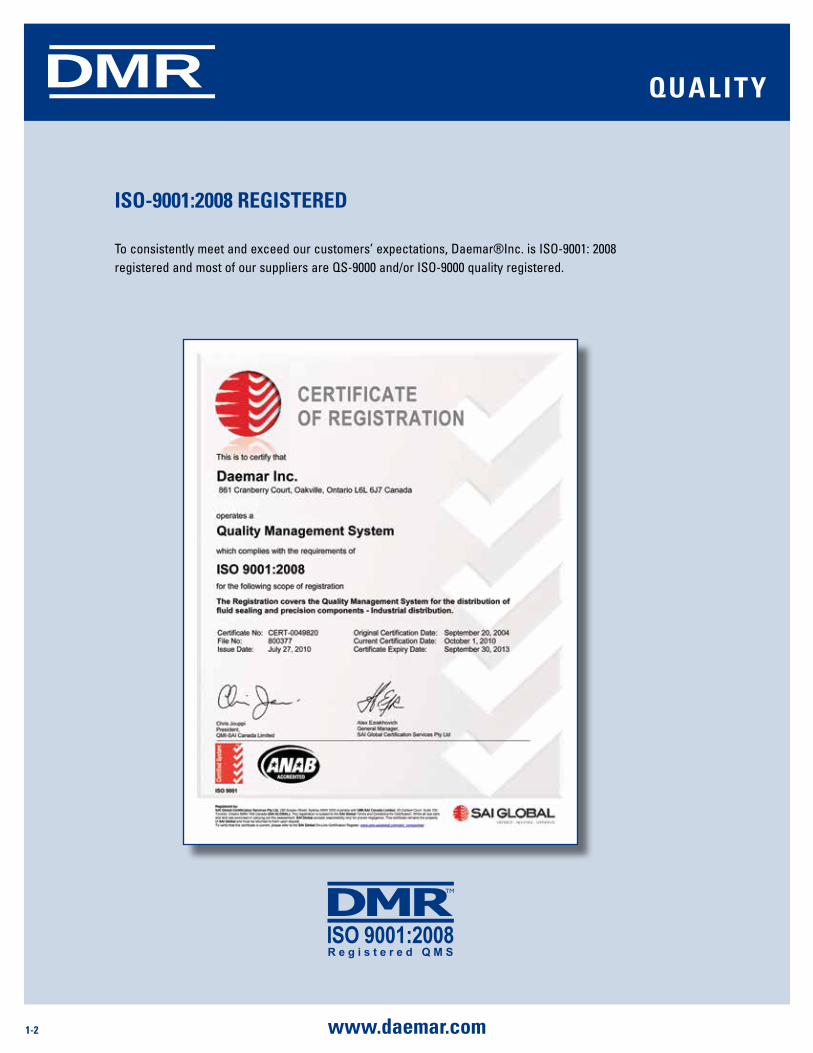
iso-9001:2008 rEgisTErEd
To consistently meet and exceed our customers’ expectations, Daemar®Inc. is ISO-9001: 2008 registered and most of our suppliers are QS-9000 and/or ISO-9000 quality registered.
1-3www.daemar.com
DMR inTroduCTion
o-ringsThe O-ring is the most widely used seal in industry today. It is simple in concept, easy to install, can be used as a double-acting seal, can seal pressures to over 5,000psi in static and dynamic applications and, best of all, is very economical.
While simple in concept, it can be very sophisticated in its applications. This catalogue is intended to give just a brief overview of O-ring design and selection. When information beyond the scope of this catalogue is required, please visit our website or contact a Daemar technical service representative.
How to specify an o-ring
O-rings are specified by calling out (1) the O-ring size (inside diameter and cross section), (2) the compound and (3) the hardness.
identifying the correct size:
O-rings are available in 349 standard inch sizes as set up by the Aerospace Standard 568 published by the society of Automotive Engineers. These sizes are designated by dash numbers as shown in the sizing tables on pages 23 to 31. For O-ring sizes other than these standard AS sizes, specify the actual dimensions desired for the inside diameter (I.D.) and the cross section (W). Measurements can be made with calipers or with one of several o-ring measurement tools (sizing chart, measurement cone). Our standard metric o-ring sizes are listed on pages 33 to 37 and standard Boss sizes on page 32.
selecting a compound:
i) Check compatibility with the fluid media to be sealed (see tables pages 13 to 20)
ii) Identify the operating temperature range required (see material specifications on pages 6 to 8)
iii) Identify other general properties that are required for the application, check these properties against the performance of various compounds in the comparison of properties table on page 4.
determining Hardness:
Now that a base compound has been selected the next step is to determine the durometer (hardness) that is needed for the application. The Durometer chart (page 5) identifies the correct level of hardness for the corresponding fluid pressure and maximum extrusion gap.
1-4 www.daemar.com
DMR
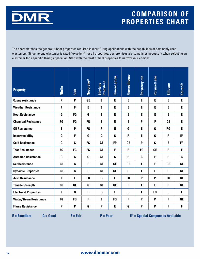
The chart matches the general rubber properties required in most O-ring applications with the capabilities of commonly used elastomers. Since no one elastomer is rated “excellent” for all properties, compromises are sometimes necessary when selecting an elastomer for a specific O-ring application. Start with the most critical properties to narrow your choices.
E = Excellent g = good F = Fair P = Poor E* = special Compounds available
Property
nitr
ile
sBr
neo
pren
e®
Ethy
lene
Pr
opyl
ene
Fluo
roca
rbon
Fluo
rosi
licon
e
Poly
arcr
ylat
e
Poly
uret
hane
silic
one
Kalr
ez®
ozone resistance P P gE E E E E E E E
Weather resistance F F E E E E E E E E
Heat resistance g Fg g E E E E E E E
Chemical resistance Fg Fg Fg E E E P F gE E
oil resistance E P Fg P E g E g Pg E
impermeability g F g g g P E g P E*
Cold resistance g g Fg gE FP gE P g E FP
Tear resistance Fg Fg Fg gE F P Fg gE P F
abrasion resistance g g g gE g P g E P g
set resistance gE g F gE gE gE F F gE gE
dynamic Properties gE g F gE gE P F E P gE
acid resistance F F Fg g E Fg P P Fg gE
Tensile strength gE gE g gE gE F F E P gE
Electrical Properties F g F g F E F Fg E F
Water/steam resistance Fg Fg F E Fg F P P F gE
Flame resistance P P g P E g P P F F
ComParison oF ProPErTiEs CHarT
1-5www.daemar.com
DMR
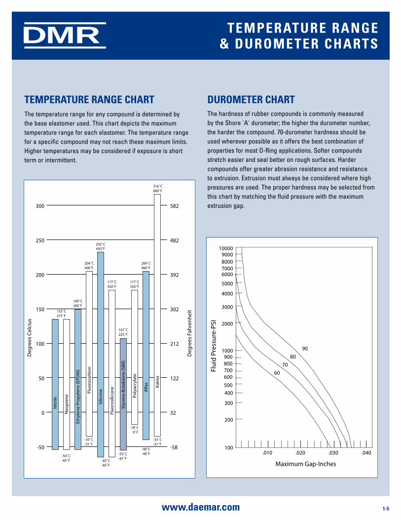
TEmPEraTurE rangE CHarTThe temperature range for any compound is determined by the base elastomer used. This chart depicts the maximum temperature range for each elastomer. The temperature range for a specific compound may not reach these maximum limits. Higher temperatures may be considered if exposure is short term or intermittent.
Deg
rees
Cel
ciu
s
Deg
rees
Fah
ren
hei
t
-50 -58
0 32
50 122
100 212
150 302
200 392
250 482
300 582
Nit
rile
Neo
pre
ne
Eth
ylen
e Pr
op
ylen
e (E
PD
M)
Flu
oro
carb
on
Silic
on
e
Flu
oro
silic
on
e
Styr
ene-
Bu
tab
ien
e (S
BR
)
Poly
acry
late
Afl
as Kal
rez
316˚C600˚F
-35˚C-31˚F
204˚C400˚F
-40˚C-40˚F
177˚C350˚F
-18˚C 0˚F
107˚C225˚F
-55˚C-67˚F
177˚C350˚F
232˚C450˚F
-65˚C-85˚F
204˚C400˚F
149˚C300˚F
135˚C275˚F
-54˚C-65˚F
-35˚C-31˚F
100
200
300
400
600700800900
1000
2000
3000
4000
5000
6000700080009000
10000
500
.010 .020 .030 .040
Flu
id P
ress
ure
-PSI
Maximum Gap-Inches
60
70
80
90
The hardness of rubber compounds is commonly measured by the Shore 'A' durometer; the higher the durometer number, the harder the compound. 70-durometer hardness should be used wherever possible as it offers the best combination of properties for most O-Ring applications. Softer compounds stretch easier and seal better on rough surfaces. Harder compounds offer greater abrasion resistance and resistance to extrusion. Extrusion must always be considered where high pressures are used. The proper hardness may be selected from this chart by matching the fluid pressure with the maximum extrusion gap.
duromETEr CHarT
TEmPEraTurE rangE & duromETEr CHarTs
1-6 www.daemar.com
DMR
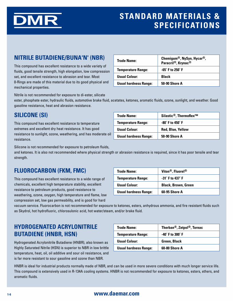
niTrilE BuTadiEnE/Buna'n' (nBr)This compound has excellent resistance to a wide variety of fluids, good tensile strength, high elongation, low compression set, and excellent resistance to abrasion and tear. Most 0-Rings are made of this material due to its good physical and mechanical properties.
Nitrile is not recommended for exposure to di-ester, silicate ester, phosphate ester, hydraulic fluids, automotive brake fluid, acetates, ketones, aromatic fluids, ozone, sunlight, and weather. Good gasoline resistance, heat and abrasion resistance.
Trade name:Chemigum®, nysyn, Hycar®, Paracril®, Krynac®
Temperature range: -65˚ F to 250˚ F
usual Colour: Black
usual hardness range: 50-90 shore a
FluoroCarBon (FKm, FmC)This compound has excellent resistance to a wide range of chemicals, excellent high temperature stability, excellent resistance to petroleum products, good resistance to weathering, ozone, oxygen, high temperature and flame, low compression set, low gas permeability, and is good for hard vacuum service. Fluorocarbon is not recommended for exposure to ketones, esters, anhydrous ammonia, and fire resistant fluids such as Skydrol, hot hydrofluoric, chlorosulonic acid, hot water/steam, and/or brake fluid.
Trade name: Viton®, Fluorel®
Temperature range: -31˚ F to 437˚ F
usual Colour: Black, Brown, green
usual hardness range: 60-95 shore a
sTandard maTErials & sPECiFiCaTions
siliConE (si)This compound has excellent resistance to temperature extremes and excellent dry heat resistance. It has good resistance to sunlight, ozone, weathering, and has moderate oil resistance.
Silicone is not recommended for exposure to petroleum fluids, and ketones. It is also not recommended where physical strength or abrasion resistance is required, since it has poor tensile and tear strength.
Trade name: silastic®, Thermoflex™
Temperature range: -80˚ F to 450˚ F
usual Colour: red, Blue, yellow
usual hardness range: 50-90 shore a
HydrogEnaTEd aCryloniTrilE BuTadiEnE (HnBr, Hsn)Hydrogenated Acrylonitrile Butadiene (HNBR), also known as Highly Saturated Nitrile (HSN) is superior to NBR in low brittle temperature, heat, oil, oil additive and sour oil resistance, and is far more resistant to sour gasoline and ozone than NBR.
HNBR is ideal for industrial products normally made of NBR, and can be used in more severe conditions with much longer service life. This compound is extensively used in R-134A cooling systems. HNBR is not recommended for exposure to ketones, esters, ethers, and aromatic fluids.
Trade name: Therban®, Zetpol®, Tornac
Temperature range: -40˚ F to 300˚ F
usual Colour: green, Black
usual hardness range: 60-80 shore a
1-7www.daemar.com
DMR sTandard maTErials & sPECiFiCaTions
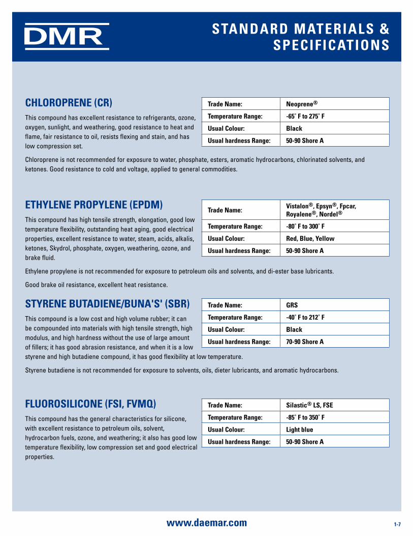
CHloroPrEnE (Cr)This compound has excellent resistance to refrigerants, ozone, oxygen, sunlight, and weathering, good resistance to heat and flame, fair resistance to oil, resists flexing and stain, and has low compression set.
Chloroprene is not recommended for exposure to water, phosphate, esters, aromatic hydrocarbons, chlorinated solvents, and ketones. Good resistance to cold and voltage, applied to general commodities.
Trade name: neoprene®
Temperature range: -65˚ F to 275˚ F
usual Colour: Black
usual hardness range: 50-90 shore a
ETHylEnE ProPylEnE (EPdm)This compound has high tensile strength, elongation, good low temperature flexibility, outstanding heat aging, good electrical properties, excellent resistance to water, steam, acids, alkalis, ketones, Skydrol, phosphate, oxygen, weathering, ozone, and brake fluid.
Ethylene propylene is not recommended for exposure to petroleum oils and solvents, and di-ester base lubricants.
Good brake oil resistance, excellent heat resistance.
Trade name:Vistalon®, Epsyn®, Fpcar, royalene®, nordel®
Temperature range: -80˚ F to 300˚ F
usual Colour: red, Blue, yellow
usual hardness range: 50-90 shore a
sTyrEnE BuTadiEnE/Buna's' (sBr)This compound is a low cost and high volume rubber; it can be compounded into materials with high tensile strength, high modulus, and high hardness without the use of large amount of fillers; it has good abrasion resistance, and when it is a low styrene and high butadiene compound, it has good flexibility at low temperature.
Styrene butadiene is not recommended for exposure to solvents, oils, dieter lubricants, and aromatic hydrocarbons.
Trade name: grs
Temperature range: -40˚ F to 212˚ F
usual Colour: Black
usual hardness range: 70-90 shore a
FluorosiliConE (Fsi, FVmQ)This compound has the general characteristics for silicone, with excellent resistance to petroleum oils, solvent, hydrocarbon fuels, ozone, and weathering; it also has good low temperature flexibility, low compression set and good electrical properties.
Trade name: silastic® ls, FsE
Temperature range: -85˚ F to 350˚ F
usual Colour: light blue
usual hardness range: 50-90 shore a
1-8 www.daemar.com
DMR
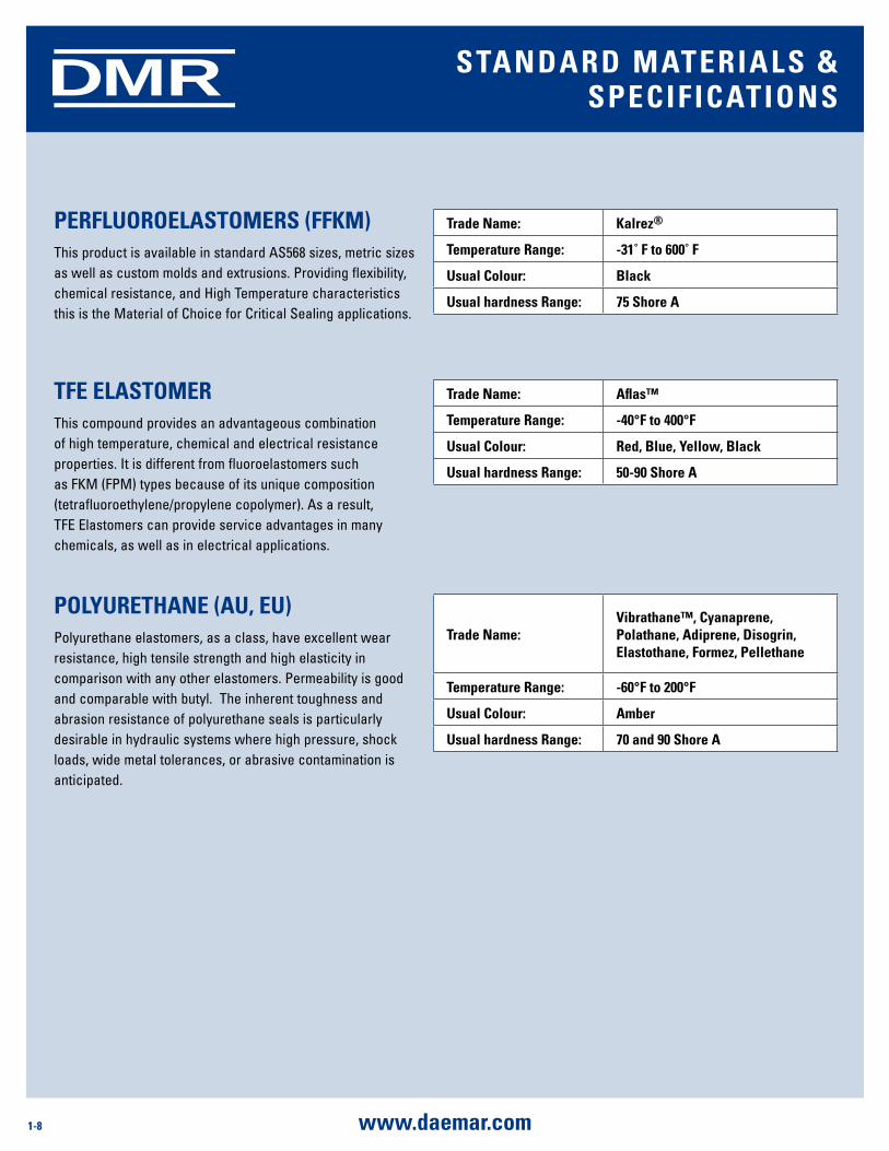
PErFluoroElasTomErs (FFKm)This product is available in standard AS568 sizes, metric sizes as well as custom molds and extrusions. Providing flexibility, chemical resistance, and High Temperature characteristics this is the Material of Choice for Critical Sealing applications.
TFE ElasTomErThis compound provides an advantageous combination of high temperature, chemical and electrical resistance properties. It is different from fluoroelastomers such as FKM (FPM) types because of its unique composition (tetrafluoroethylene/propylene copolymer). As a result, TFE Elastomers can provide service advantages in many chemicals, as well as in electrical applications.
sTandard maTErials & sPECiFiCaTions
Trade name: Kalrez®
Temperature range: -31˚ F to 600˚ F
usual Colour: Black
usual hardness range: 75 shore a
Trade name: aflas™
Temperature range: -40°F to 400°F
usual Colour: red, Blue, yellow, Black
usual hardness range: 50-90 shore a
PolyurETHanE (au, Eu)Polyurethane elastomers, as a class, have excellent wear resistance, high tensile strength and high elasticity in comparison with any other elastomers. Permeability is good and comparable with butyl. The inherent toughness and abrasion resistance of polyurethane seals is particularly desirable in hydraulic systems where high pressure, shock loads, wide metal tolerances, or abrasive contamination is anticipated.
Trade name:Vibrathane™, Cyanaprene, Polathane, adiprene, disogrin, Elastothane, Formez, Pellethane
Temperature range: -60°F to 200°F
usual Colour: amber
usual hardness range: 70 and 90 shore a
1-9www.daemar.com
DMR
THE sEal To TrusT For TougH sEaling aPPliCaTionsFor demanding sealing applications when customers require the very best, Kalrez® parts manufactured only by DuPont Performance Elastomers, are the elastomer seals of choice. Supplied in standard O-rings or custom shapes, Kalrez® resists over 1,800 different chemicals while offering the high temperature stability of PTFE (327°C). Advanced properties help maintain seal integrity, reduce maintenance and operating costs and improve safety. Kalrez® parts provide reliable, long-term service with a wide range of aggressive industrial and electronic grade chemicals. It is used in highly aggressive chemical processing, semiconductor wafer processing, pharmaceutical, oil and gas recovery, aerospace and petroleum applications. Production facilities for Kalrez® are ISO 9000 and AS 9100 registered.
indusTriEsFor over 25 years, Kalrez® perfluoroelastomer parts have been providing the ultimate in sealing performance in the harshest processing environments. Some of the industries and applications in which Kalrez® parts provide superior performance include:
Chemical Processing - In pumps, valves, reactors, flange joints and other equipment, Kalrez® parts—whether O-rings, custom shapes or valve stem packing systems—are proving their value year in and year out as the best choice for long-term, reliable service.
semiconductor - The success of Kalrez® has been field-proven in the manufacture of semiconductors, where processing steps can involve extremes of both thermal and chemical exposure.
Food and Pharmaceuticals - Food and Pharmaceutical applications require the ultimate in cleanliness and Kalrez® parts provide that along with excellent sealing performance in a wide range of aggressive media over a broad range of temperatures. The introduction of FDA-compliant Kalrez® compounds offers a new standard of sealing solutions with full traceability, low contamination from extractables and excellent seal life.
aerospace - High-performance Kalrez® parts provide reliable and long-lasting sealing performance for the military, commercial and general aviation industry. They are used as oil seals in gas turbine engines and air delivery systems.
oil and gas - Kalrez® parts stand up to severe down-hole conditions—from high pressures and temperatures, to aggressive sour gas and corrosive fluids.
Whether you are in the chemical processing industry, oil and gas, wafer processing or thousands of other demanding applications, Kalrez® seals can extend your mean time between failures and reduce your risk of seal failure.
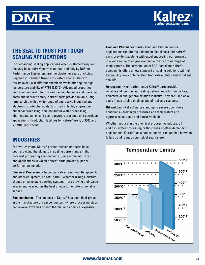
Temperature Limits
600°F
500°F
400°F
300°F
200°F
100°F
300°C
250°C
200°C
150°C
100°C
50°C
Fluoroelastomer
KALREZ ®
Silicone
Fluorosilicone
1-10 www.daemar.com
DMR
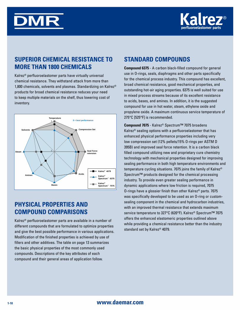
PHysiCal ProPErTiEs and ComPound ComParisonsKalrez® perfluoroelastomer parts are available in a number of different compounds that are formulated to optimize properties and give the best possible performance in various applications. Modification of the finished properties is achieved by use of fillers and other additives. The table on page 13 summarizes the basic physical properties of the most commonly used compounds. Descriptions of the key attributes of each compound and their general areas of application follow.
sTandard ComPoundsCompound 6375 - A carbon black-filled compound for general use in O-rings, seals, diaphragms and other parts specifically for the chemical process industry. This compound has excellent, broad chemical resistance, good mechanical properties, and outstanding hot-air aging properties. 6375 is well suited for use in mixed process streams because of its excellent resistance to acids, bases, and amines. In addition, it is the suggested compound for use in hot water, steam, ethylene oxide and propylene oxide. A maximum continuous service temperature of 275°C [525°F] is recommended.
Compound 7075 - Kalrez® Spectrum™ 7075 broadens Kalrez® sealing options with a perfluoroelastomer that has enhanced physical performance properties including very low compression set (12% pellets/15% O-rings per ASTM D 395B) and improved seal force retention. It is a carbon black filled compound utilizing new and proprietary cure chemistry technology with mechanical properties designed for improving sealing performance in both high temperature environments and temperature cycling situations. 7075 joins the family of Kalrez® Spectrum™ products designed for the chemical processing industry. To provide even greater sealing performance in dynamic applications where low friction is required, 7075 O-rings have a glossier finish than other Kalrez® parts. 7075 was specifically developed to be used as an O-ring or custom-sealing component in the chemical and hydrocarbon industries, with an improved thermal resistance that extends maximum service temperature to 327°C (620°F). Kalrez® Spectrum™ 7075 offers the enhanced elastomeric properties outlined above while providing a chemical resistance better than the industry standard set by Kalrez® 4079.
suPErior CHEmiCal rEsisTanCE To morE THan 1800 CHEmiCalsKalrez® perfluoroelastomer parts have virtually universal chemical resistance. They withstand attack from more than 1,800 chemicals, solvents and plasmas. Standardizing on Kalrez® products for broad chemical resistance reduces your need to keep multiple materials on the shelf, thus lowering cost of inventory.
Temperature5
0
Compression Set
Seal Forceretension
Acids
Bases
Amines
Steam
Solvents
5 = best performance
Kalrez® 4079
Kalrez®
Spectrum™ 6375
Kalrez®
Spectrum™ 7075
1-11www.daemar.com
DMR
Compound 3018 - A carbon black-filled compound similar to Compound 1050LF, except for higher hardness/modulus. This compound is good in hot water/steam and offers the best high pressure extrusion resistance. Generally used in oil field and process industry applications where these properties coupled with good amine and general chemical resistance are required. A maximum service temperature of 288°C [550°F] is recommended.
Compound 2037 - A non-black-filled compound that is well suited for selected applications in the semiconductor and other markets that demand high purity elastomers. Compound 2037 has excellent chemical resistance exhibiting low swell in organic acids, inorganic acids, esters, ketones, and aldehydes. It also offers good mechanical properties. A maximum service temperature of 218°C [425°F] is recommended.
Compound 6380 - Specifically developed to extend service lifetime in chemical and hydrocarbon processes involving hot, aggressive amines, strong acids and oxidizing media. Offering excellent overall chemical resistance and mechanical properties for static and dynamic sealing applications in harsh cheimcal plant processes at temperatures up to 225C. Compound 6380 exhibited very low swell after 672 hours exposure to ethylene diamine, ethanolamine and ammonium hydroxide, compared to alternative perfluoroelastomer parts commonly specified for such environments. Manufactured in an easily identifiable cream colour.
Compound 9100 - An amber translucent compond targeted specifically for deposition process applications, i.e., HDPCVD, PECVD, SACVD, Metal CVD, ALD, etc. It also exhibits excellent performance in “select” etching and ashing/stripping process applications. Specifically designed fro low erosion and ultra-low particle generation in harsh plasma environments. It offers outstanding thermal stability, very low outgassing as well as excellent elastic recovery and mechanical strength properties and is well suited for both static and dynamic sealing applications. A maximum continuous service temperature of 300C is suggested. Ultrapure post-cleaning and packaging is standard for all parts made from compound 9100.
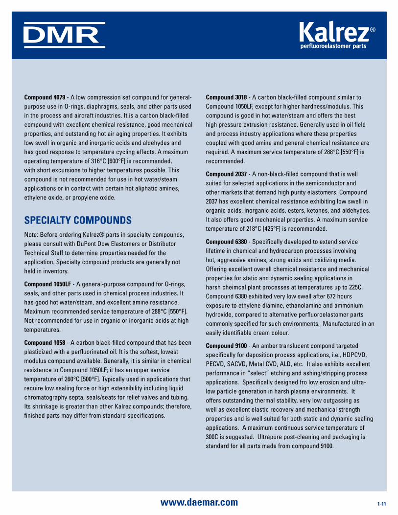
Compound 4079 - A low compression set compound for general-purpose use in O-rings, diaphragms, seals, and other parts used in the process and aircraft industries. It is a carbon black-filled compound with excellent chemical resistance, good mechanical properties, and outstanding hot air aging properties. It exhibits low swell in organic and inorganic acids and aldehydes and has good response to temperature cycling effects. A maximum operating temperature of 316°C [600°F] is recommended, with short excursions to higher temperatures possible. This compound is not recommended for use in hot water/steam applications or in contact with certain hot aliphatic amines, ethylene oxide, or propylene oxide.
sPECialTy ComPoundsNote: Before ordering Kalrez® parts in specialty compounds, please consult with DuPont Dow Elastomers or Distributor Technical Staff to determine properties needed for the application. Specialty compound products are generally not held in inventory.
Compound 1050lF - A general-purpose compound for O-rings, seals, and other parts used in chemical process industries. It has good hot water/steam, and excellent amine resistance. Maximum recommended service temperature of 288°C [550°F]. Not recommended for use in organic or inorganic acids at high temperatures.
Compound 1058 - A carbon black-filled compound that has been plasticized with a perfluorinated oil. It is the softest, lowest modulus compound available. Generally, it is similar in chemical resistance to Compound 1050LF; it has an upper service temperature of 260°C [500°F]. Typically used in applications that require low sealing force or high extensibility including liquid chromatography septa, seals/seats for relief valves and tubing. Its shrinkage is greater than other Kalrez compounds; therefore, finished parts may differ from standard specifications.
1-12 www.daemar.com
DMR
CHEmiCal rEsisTanCEBecause Kalrez® has outstanding chemical resistance, it withstands nearly all classes of chemicals. With this combination of high thermal stability and excellent chemical resistance, the Kalrez® perfluoroelastomer parts rating may be conservative, as actual field experience and the example above have demonstrated.
In comparing the chemical and fluid resistance of Kalrez® perfluoroelastomers to that of Teflon® fluoropolymer resins, certain differences should be kept in mind:
• Kalrez®isanamorphouslow-modulusrubberwhereasTeflon® is a crystalline high-modulus plastic. In fluid environments where high permeation occurs, Kalrez® will probably swell to a greater extent than Teflon®, even though the polymer is not chemically attacked. Environments in
which this is most noticeable are fully halogenated solvents, Freon®, and Freon® alternatives. Service ability of Kalrez® in these environments will be dependent upon the specifics of the application.
• Aswithallelastomers,itisnecessarytocompoundKalrez® perfluoroelastomers with fillers and curatives to gain desired mechanical properties for functionality. In a limited number of environments, even though the polymer is stable, the fillers and curative systems may interact with the chemicals. However, because the level of fillers in Kalrez® perfluoroelastomers is much lower than in most other elastomers, such filler interactions are generally negligible with Kalrez® parts. Where such interactions can occur, such as in highly oxidative environments, service performance is dependent on the conditions of the application and may be affected by compound choice.
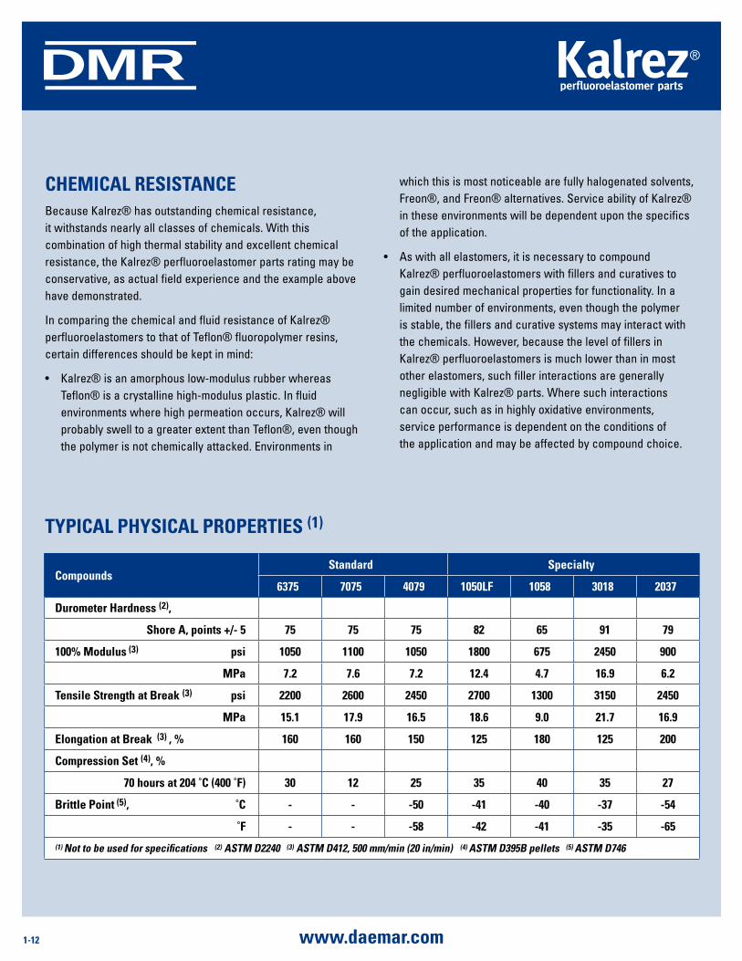
Compoundsstandard specialty
6375 7075 4079 1050lF 1058 3018 2037
durometer Hardness (2),
shore a, points +/- 5 75 75 75 82 65 91 79
100% modulus (3) psi 1050 1100 1050 1800 675 2450 900
mPa 7.2 7.6 7.2 12.4 4.7 16.9 6.2
Tensile strength at Break (3) psi 2200 2600 2450 2700 1300 3150 2450
mPa 15.1 17.9 16.5 18.6 9.0 21.7 16.9
Elongation at Break (3) , % 160 160 150 125 180 125 200
Compression set (4), %
70 hours at 204 ˚C (400 ˚F) 30 12 25 35 40 35 27
Brittle Point (5), ˚C - - -50 -41 -40 -37 -54
˚F - - -58 -42 -41 -35 -65
(1) not to be used for specifications (2) asTm d2240 (3) asTm d412, 500 mm/min (20 in/min) (4) asTm d395B pellets (5) asTm d746
TyPiCal PHysiCal ProPErTiEs (1)
1-13www.daemar.com
DMR
Because each application is unique, it is recommended that users of Kalrez® perfluoroelastomer parts always conduct their own evaluations to determine the suitability of Kalrez® for their application. Because of laboratory constraints and differences in field applications, the results shown in this technical information may be based on conditions that may not necessarily reflect actual operating environments for a specific application. Additionally, many elastomeric materials may show excellent chemical resistance to pure reagents in relatively short-term laboratory tests. However, they may fail in actual service because of chemical attack by additives and/or impurities. Kalrez® perfluoro-elastomer parts, with their near-universal chemical resistance, provide an extra degree of safety against these unknown corrosive influences. Case histories are available from Daemar detailing proven performance of Kalrez® parts in over 100 specific chemical applications. Information on test performance in a limited number of specific chemicals is also available through your authorized Kalrez® distributor.
CauTionKalrez® perfluoroelastomer parts, like all fluorinated products, should not be exposed to molten or gaseous alkali metals, such as sodium and potassium, because a highly exothermic reaction may occur. At elevated temperatures above 100°C (212°F), service life may be significantly reduced in fluids containing high concentrations of some diamines, nitric acid, and basic phenols. Kalrez® parts should always be tested for suitability.
1-14 www.daemar.com
DMR mETal dETECTaBlE o-rings
Food and PHarmaCEuTiCal indus-Try sEalsAs a result of excessive use, shearing and damage can occur to equipment causing undetectable product contamination. Metal detectables can eliminate product recall, lower product loss and decrease the risk of elastomers consumed in finished product.
System Protection with Metal Detectable O-Rings
A common problem with component and filler parts is excessive wear and tear. When rubber breaks off a moving part it can migrate through your system and into your product. Searching for and locating fragmented rubber parts is a costly, time consuming and inconclusive process requiring expensive x-ray equipment, manual observation and an extensive maintenance program. Not locating a worn and lost rubber piece can have an even costlier outcome. By manufacturing a standard elastomer with a metal impregnated compound, displaced rubber material can now be located by an in-line metal detector. This alarm enables your system to instantly reject contaminated product.
Benefits of metal detectable o-rings include:
• Easilydetectlostelastomericfragments.• Preventproductrecall.• Lowerproductloss.• Stopdistributionofcontaminatedproduct.• ForuseinstandardOEMequipment.• Designedformicrobial,high-temperatureandmechanical
applications.• Availableinhygienicseals,screens,sheets,extrusions,valve stems and filler boots.
Typical applications:
• Food• Beverage• Pharmaceutical
detectable o-ring materials:
• Buna• EPDM• FKM• Silicone• Tuf-Steel™
meets industry standards:
• Elastomers meet Title 21 CFR 177.2600• Tuf-Steel meets Title 21 CFR 177.1550• Meets USDA Hazard Analysis and Critical Control points.• Detectable metal additive meets the latest revision of the
Food Chemicals Codex *• Animal Derived Ingredient Free†
* The Food Chemicals Codex Project is an activity of the food and nutrition board of the Institute of Medicine and is supported by the U.S. Food and Drug Administration.
™ Tuf-Steel and ADI Free are trademarks of Rubber Fab Technologies Group.
† Buna is not an ADI Free elastomer
Please Contact a Daemar Customer Service Repersentative for all your inquiries. Or visit our website www.daemar.com.
1-15www.daemar.com
DMR
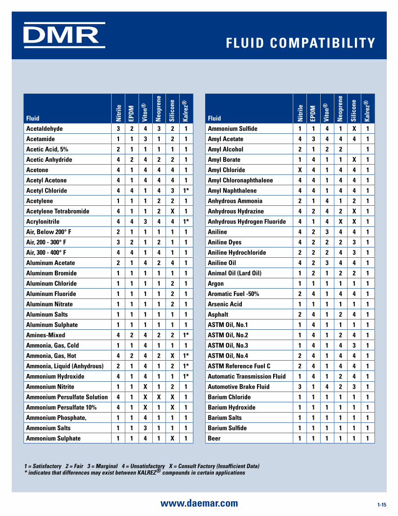
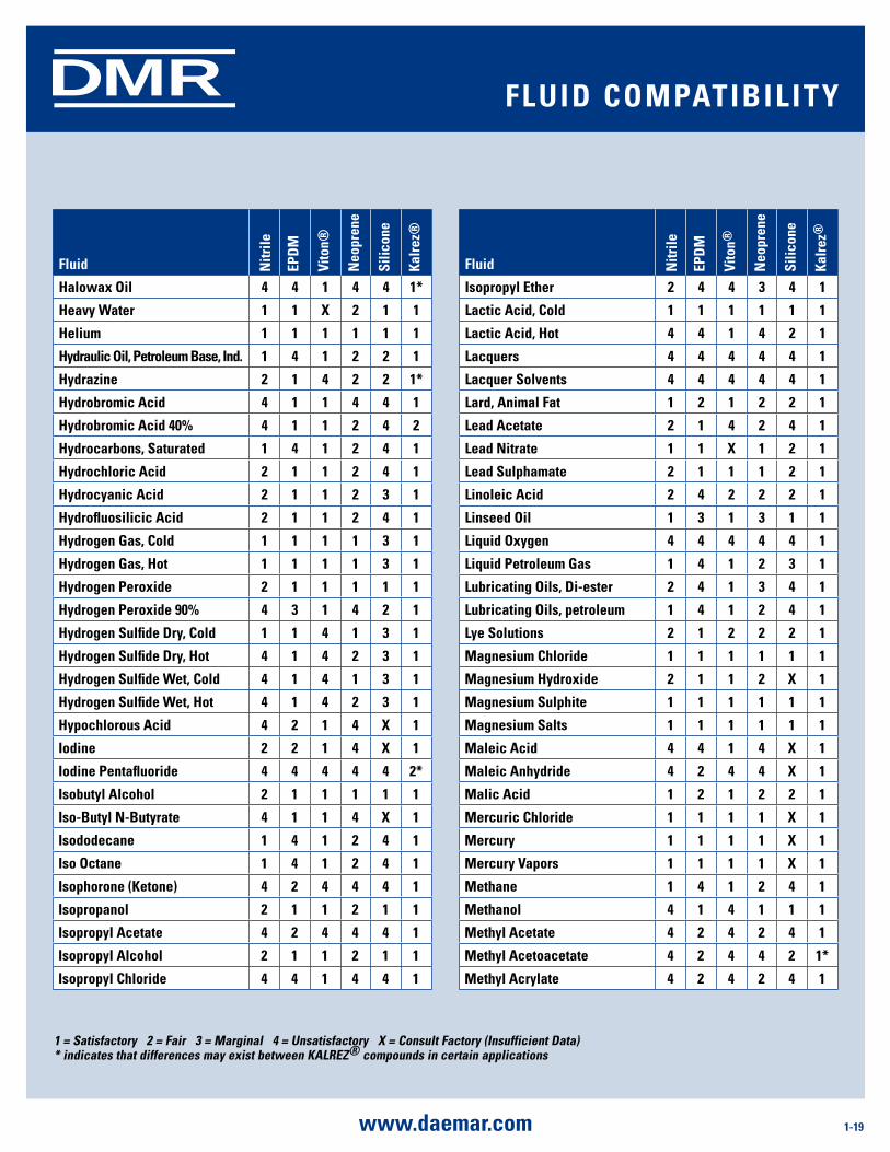
1 = satisfactory 2 = Fair 3 = marginal 4 = unsatisfactory X = Consult Factory (insufficient data)* indicates that differences may exist between KalrEZ® compounds in certain applications
Fluid nitr
ile
EPd
m
Vito
n®
neo
pren
e
silic
one
Kalr
ez®
acetaldehyde 3 2 4 3 2 1
acetamide 1 1 3 1 2 1
acetic acid, 5% 2 1 1 1 1 1
acetic anhydride 4 2 4 2 2 1
acetone 4 1 4 4 4 1
acetyl acetone 4 1 4 4 4 1
acetyl Chloride 4 4 1 4 3 1*
acetylene 1 1 1 2 2 1
acetylene Tetrabromide 4 1 1 2 X 1
acrylonitrile 4 4 3 4 4 1*
air, Below 200° F 2 1 1 1 1 1
air, 200 - 300° F 3 2 1 2 1 1
air, 300 - 400° F 4 4 1 4 1 1
aluminum acetate 2 1 4 2 4 1
aluminum Bromide 1 1 1 1 1 1
aluminum Chloride 1 1 1 1 2 1
aluminum Fluoride 1 1 1 1 2 1
aluminum nitrate 1 1 1 1 2 1
aluminum salts 1 1 1 1 1 1
aluminum sulphate 1 1 1 1 1 1
amines-mixed 4 2 4 2 2 1*
ammonia, gas, Cold 1 1 4 1 1 1
ammonia, gas, Hot 4 2 4 2 X 1*
ammonia, liquid (anhydrous) 2 1 4 1 2 1*
ammonium Hydroxide 4 1 4 1 1 1*
ammonium nitrite 1 1 X 1 2 1
ammonium Persulfate solution 4 1 X X X 1
ammonium Persulfate 10% 4 1 X 1 X 1
ammonium Phosphate, 1 1 4 1 1 1
ammonium salts 1 1 3 1 1 1
ammonium sulphate 1 1 4 1 X 1
Fluid nitr
ile
EPd
m
Vito
n®
neo
pren
e
s ilic
one
Kalr
ez®
ammonium sulfide 1 1 4 1 X 1
amyl acetate 4 3 4 4 4 1
amyl alcohol 2 1 2 2 1
amyl Borate 1 4 1 1 X 1
amyl Chloride X 4 1 4 4 1
amyl Chloronaphthalene 4 4 1 4 4 1
amyl naphthalene 4 4 1 4 4 1
anhydrous ammonia 2 1 4 1 2 1
anhydrous Hydrazine 4 2 4 2 X 1
anhydrous Hydrogen Fluoride 4 1 4 X X 1
aniline 4 2 3 4 4 1
aniline dyes 4 2 2 2 3 1
aniline Hydrochloride 2 2 2 4 3 1
aniline oil 4 2 3 4 4 1
animal oil (lard oil) 1 2 1 2 2 1
argon 1 1 1 1 1 1
aromatic Fuel -50% 2 4 1 4 4 1
arsenic acid 1 1 1 1 1 1
asphalt 2 4 1 2 4 1
asTm oil, no.1 1 4 1 1 1 1
asTm oil, no.2 1 4 1 2 4 1
asTm oil, no.3 1 4 1 4 3 1
asTm oil, no.4 2 4 1 4 4 1
asTm reference Fuel C 2 4 1 4 4 1
automatic Transmission Fluid 1 4 1 2 4 1
automotive Brake Fluid 3 1 4 2 3 1
Barium Chloride 1 1 1 1 1 1
Barium Hydroxide 1 1 1 1 1 1
Barium salts 1 1 1 1 1 1
Barium sulfide 1 1 1 1 1 1
Beer 1 1 1 1 1 1
Fluid ComPaTiBiliTy
1-16 www.daemar.com
DMR
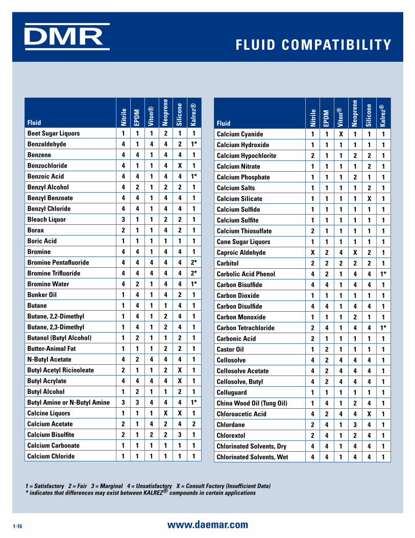
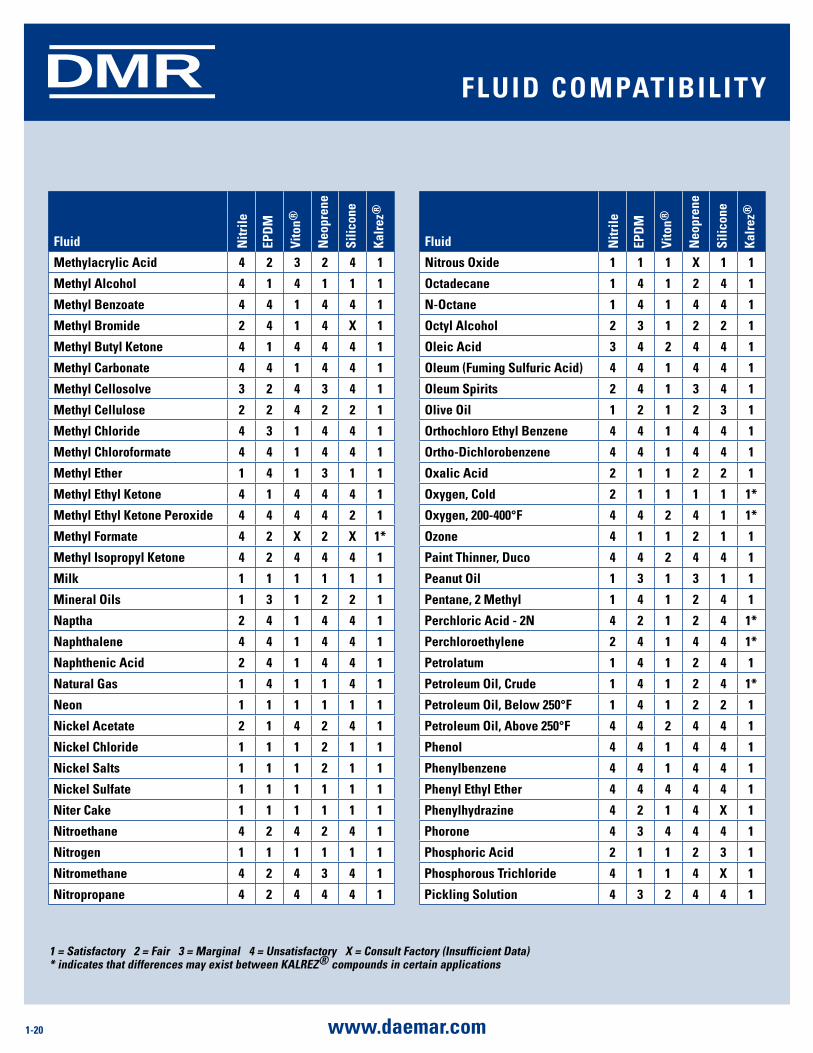
1 = satisfactory 2 = Fair 3 = marginal 4 = unsatisfactory X = Consult Factory (insufficient data)* indicates that differences may exist between KalrEZ® compounds in certain applications
Fluid nitr
ile
EPd
m
Vito
n®
neo
pren
e
silic
one
Kalr
ez®
Beet sugar liquors 1 1 1 2 1 1
Benzaldehyde 4 1 4 4 2 1*
Benzene 4 4 1 4 4 1
Benzochloride 4 1 1 4 X 1
Benzoic acid 4 4 1 4 4 1*
Benzyl alcohol 4 2 1 2 2 1
Benzyl Benzoate 4 4 1 4 4 1
Benzyl Chloride 4 4 1 4 4 1
Bleach liquor 3 1 1 2 2 1
Borax 2 1 1 4 2 1
Boric acid 1 1 1 1 1 1
Bromine 4 4 1 4 4 1
Bromine Pentafluoride 4 4 4 4 4 2*
Bromine Trifluoride 4 4 4 4 4 2*
Bromine Water 4 2 1 4 4 1*
Bunker oil 1 4 1 4 2 1
Butane 1 4 1 1 4 1
Butane, 2,2-dimethyl 1 4 1 2 4 1
Butane, 2,3-dimethyl 1 4 1 2 4 1
Butanol (Butyl alcohol) 1 2 1 1 2 1
Butter-animal Fat 1 1 1 2 2 1
n-Butyl acetate 4 2 4 4 4 1
Butyl acetyl ricinoleate 2 1 1 2 X 1
Butyl acrylate 4 4 4 4 X 1
Butyl alcohol 1 2 1 1 2 1
Butyl amine or n-Butyl amine 3 3 4 4 4 1*
Calcine liquors 1 1 1 X X 1
Calcium acetate 2 1 4 2 4 2
Calcium Bisulfite 2 1 2 2 3 1
Calcium Carbonate 1 1 1 1 1 1
Calcium Chloride 1 1 1 1 1 1
Fluid nitr
ile
EPd
m
Vito
n®
neo
pren
e
s ilic
one
Kalr
ez®
Calcium Cyanide 1 1 X 1 1 1
Calcium Hydroxide 1 1 1 1 1 1
Calcium Hypochlorite 2 1 1 2 2 1
Calcium nitrate 1 1 1 1 2 1
Calcium Phosphate 1 1 1 2 1 1
Calcium salts 1 1 1 1 2 1
Calcium silicate 1 1 1 1 X 1
Calcium sulfide 1 1 1 1 1 1
Calcium sulfite 1 1 1 1 1 1
Calcium Thiosulfate 2 1 1 1 1 1
Cane sugar liquors 1 1 1 1 1 1
Caproic aldehyde X 2 4 X 2 1
Carbitol 2 2 2 2 2 1
Carbolic acid Phenol 4 2 1 4 4 1*
Carbon Bisulfide 4 4 1 4 4 1
Carbon dioxide 1 1 1 1 1 1
Carbon disulfide 4 4 1 4 4 1
Carbon monoxide 1 1 1 2 1 1
Carbon Tetrachloride 2 4 1 4 4 1*
Carbonic acid 2 1 1 1 1 1
Castor oil 1 2 1 1 1 1
Cellosolve 4 2 4 4 4 1
Cellosolve acetate 4 2 4 4 4 1
Cellosolve, Butyl 4 2 4 4 4 1
Celluguard 1 1 1 1 1 1
China Wood oil (Tung oil) 1 4 1 2 4 1
Chloroacetic acid 4 2 4 4 X 1
Chlordane 2 4 1 3 4 1
Chlorextol 2 4 1 2 4 1
Chlorinated solvents, dry 4 4 1 4 4 1
Chlorinated solvents, Wet 4 4 1 4 4 1
Fluid ComPaTiBiliTy
1-17www.daemar.com
DMR
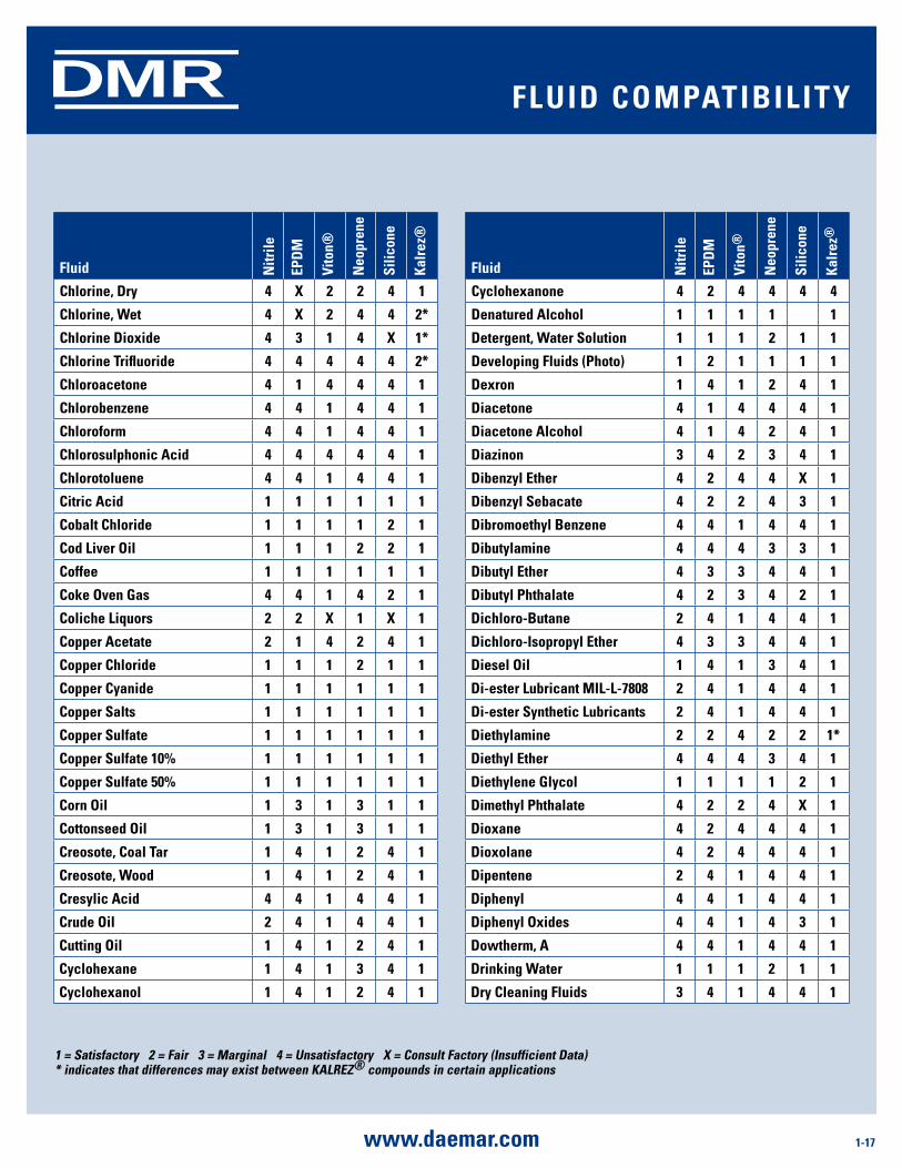
1 = satisfactory 2 = Fair 3 = marginal 4 = unsatisfactory X = Consult Factory (insufficient data)* indicates that differences may exist between KalrEZ® compounds in certain applications
Fluid nitr
ile
EPd
m
Vito
n®
neo
pren
e
silic
one
Kalr
ez®
Chlorine, dry 4 X 2 2 4 1
Chlorine, Wet 4 X 2 4 4 2*
Chlorine dioxide 4 3 1 4 X 1*
Chlorine Trifluoride 4 4 4 4 4 2*
Chloroacetone 4 1 4 4 4 1
Chlorobenzene 4 4 1 4 4 1
Chloroform 4 4 1 4 4 1
Chlorosulphonic acid 4 4 4 4 4 1
Chlorotoluene 4 4 1 4 4 1
Citric acid 1 1 1 1 1 1
Cobalt Chloride 1 1 1 1 2 1
Cod liver oil 1 1 1 2 2 1
Coffee 1 1 1 1 1 1
Coke oven gas 4 4 1 4 2 1
Coliche liquors 2 2 X 1 X 1
Copper acetate 2 1 4 2 4 1
Copper Chloride 1 1 1 2 1 1
Copper Cyanide 1 1 1 1 1 1
Copper salts 1 1 1 1 1 1
Copper sulfate 1 1 1 1 1 1
Copper sulfate 10% 1 1 1 1 1 1
Copper sulfate 50% 1 1 1 1 1 1
Corn oil 1 3 1 3 1 1
Cottonseed oil 1 3 1 3 1 1
Creosote, Coal Tar 1 4 1 2 4 1
Creosote, Wood 1 4 1 2 4 1
Cresylic acid 4 4 1 4 4 1
Crude oil 2 4 1 4 4 1
Cutting oil 1 4 1 2 4 1
Cyclohexane 1 4 1 3 4 1
Cyclohexanol 1 4 1 2 4 1
Fluid nitr
ile
EPd
m
Vito
n®
neo
pren
e
s ilic
one
Kalr
ez®
Cyclohexanone 4 2 4 4 4 4
denatured alcohol 1 1 1 1 1
detergent, Water solution 1 1 1 2 1 1
developing Fluids (Photo) 1 2 1 1 1 1
dexron 1 4 1 2 4 1
diacetone 4 1 4 4 4 1
diacetone alcohol 4 1 4 2 4 1
diazinon 3 4 2 3 4 1
dibenzyl Ether 4 2 4 4 X 1
dibenzyl sebacate 4 2 2 4 3 1
dibromoethyl Benzene 4 4 1 4 4 1
dibutylamine 4 4 4 3 3 1
dibutyl Ether 4 3 3 4 4 1
dibutyl Phthalate 4 2 3 4 2 1
dichloro-Butane 2 4 1 4 4 1
dichloro-isopropyl Ether 4 3 3 4 4 1
diesel oil 1 4 1 3 4 1
di-ester lubricant mil-l-7808 2 4 1 4 4 1
di-ester synthetic lubricants 2 4 1 4 4 1
diethylamine 2 2 4 2 2 1*
diethyl Ether 4 4 4 3 4 1
diethylene glycol 1 1 1 1 2 1
dimethyl Phthalate 4 2 2 4 X 1
dioxane 4 2 4 4 4 1
dioxolane 4 2 4 4 4 1
dipentene 2 4 1 4 4 1
diphenyl 4 4 1 4 4 1
diphenyl oxides 4 4 1 4 3 1
dowtherm, a 4 4 1 4 4 1
drinking Water 1 1 1 2 1 1
dry Cleaning Fluids 3 4 1 4 4 1
Fluid ComPaTiBiliTy
1-18 www.daemar.com
DMR
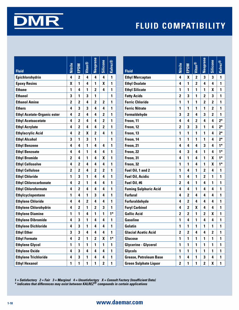
1 = satisfactory 2 = Fair 3 = marginal 4 = unsatisfactory X = Consult Factory (insufficient data)* indicates that differences may exist between KalrEZ® compounds in certain applications
Fluid nitr
ile
EPd
m
Vito
n®
neo
pren
e
silic
one
Kalr
ez®
Ethyl mercaptan 4 X 2 3 3 1
Ethyl oxalate 4 1 2 4 4 1
Ethyl silicate 1 1 1 1 X 1
Fatty acids 2 3 1 2 3 1
Ferric Chloride 1 1 1 2 2 1
Ferric nitrate 1 1 1 1 2 1
Formaldehyde 3 2 4 3 2 1
Freon, 11 4 4 2 4 4 2*
Freon, 12 2 3 3 1 4 2*
Freon, 13 1 1 1 1 4 2*
Freon, 14 1 1 1 1 4 2*
Freon, 21 4 4 4 3 4 1*
Freon, 22 4 3 4 1 4 1*
Freon, 31 4 1 4 1 X 1*
Freon, 32 1 1 4 1 X 1*
Fuel oil, 1 and 2 1 4 1 2 4 1
Fuel oil, acidic 1 4 1 2 1 1
Fuel oil, #6 2 4 1 4 1 1
Fuming sulphuric acid 4 4 1 4 4 1
Furfural 4 2 4 4 4 1
Furfuraldehyde 4 2 4 4 4 1
Furyl Carbinol 4 2 X 4 4 1
gallic acid 2 2 1 2 X 1
gasoline 1 4 1 4 4 1
gelatin 1 1 1 1 1 1
glacial acetic acid 2 2 4 4 2 1
glucose 1 1 1 1 1 1
glycerine - glycerol 1 1 1 1 1 1
glycols 1 1 1 1 1 1
grease, Petroleum Base 1 4 1 3 4 1
green sulphate liquor 2 1 1 2 X 1
Fluid nitr
ile
EPd
m
Vito
n®
neo
pren
e
silic
one
Kalr
ez®
Epichlorohydrin 4 2 4 4 4 1
Epoxy resins X 1 4 1 X 1
Ethane 1 4 1 2 4 1
Ethanol 3 1 3 1 1
Ethanol amine 2 2 4 2 2 1
Ethers 4 3 3 4 4 1
Ethyl acetate-organic ester 4 2 4 4 2 1
Ethyl acetoacetate 4 2 4 4 2 1
Ethyl acrylate 4 2 4 4 2 1
Ethylacrylic acid 4 2 X 2 4 1
Ethyl alcohol 3 1 3 1 1
Ethyl Benzene 4 4 1 4 4 1
Ethyl Benzoate 4 4 1 4 4 1
Ethyl Bromide 2 4 1 4 X 1
Ethyl Cellosolve 4 2 4 4 4 1
Ethyl Cellulose 2 2 4 2 2 1
Ethyl Chloride 1 3 1 4 4 1
Ethyl Chlorocarbonate 4 2 1 4 4 1
Ethyl Chloroformate 4 2 4 4 4 1
Ethylcyclopentane 1 4 1 3 4 1
Ethylene Chloride 4 4 2 4 4 1
Ethylene Chlorohydrin 4 2 1 2 3 1
Ethylene diamine 1 1 4 1 1 1*
Ethylene dibromide 4 3 1 4 4 1
Ethylene dichloride 4 3 1 4 4 1
Ethyl Ether 3 3 4 4 4 1
Ethyl Formate 4 2 1 2 X 1*
Ethylene glycol 1 1 1 1 1 1
Ethylene oxide 4 3 4 4 4 1
Ethylene Trichloride 4 3 1 4 4 1
Ethyl Hexanol 1 1 1 1 2 1
Fluid ComPaTiBiliTy
1-19www.daemar.com
DMR
1 = satisfactory 2 = Fair 3 = marginal 4 = unsatisfactory X = Consult Factory (insufficient data)* indicates that differences may exist between KalrEZ® compounds in certain applications
Fluid nitr
ile
EPd
m
Vito
n®
neo
pren
e
s ilic
one
Kalr
ez®
isopropyl Ether 2 4 4 3 4 1
lactic acid, Cold 1 1 1 1 1 1
lactic acid, Hot 4 4 1 4 2 1
lacquers 4 4 4 4 4 1
lacquer solvents 4 4 4 4 4 1
lard, animal Fat 1 2 1 2 2 1
lead acetate 2 1 4 2 4 1
lead nitrate 1 1 X 1 2 1
lead sulphamate 2 1 1 1 2 1
linoleic acid 2 4 2 2 2 1
linseed oil 1 3 1 3 1 1
liquid oxygen 4 4 4 4 4 1
liquid Petroleum gas 1 4 1 2 3 1
lubricating oils, di-ester 2 4 1 3 4 1
lubricating oils, petroleum 1 4 1 2 4 1
lye solutions 2 1 2 2 2 1
magnesium Chloride 1 1 1 1 1 1
magnesium Hydroxide 2 1 1 2 X 1
magnesium sulphite 1 1 1 1 1 1
magnesium salts 1 1 1 1 1 1
maleic acid 4 4 1 4 X 1
maleic anhydride 4 2 4 4 X 1
malic acid 1 2 1 2 2 1
mercuric Chloride 1 1 1 1 X 1
mercury 1 1 1 1 X 1
mercury Vapors 1 1 1 1 X 1
methane 1 4 1 2 4 1
methanol 4 1 4 1 1 1
methyl acetate 4 2 4 2 4 1
methyl acetoacetate 4 2 4 4 2 1*
methyl acrylate 4 2 4 2 4 1
Fluid nitr
ile
EPd
m
Vito
n®
neo
pren
e
silic
one
Kalr
ez®
Halowax oil 4 4 1 4 4 1*
Heavy Water 1 1 X 2 1 1
Helium 1 1 1 1 1 1
Hydraulic oil, Petroleum Base, ind. 1 4 1 2 2 1
Hydrazine 2 1 4 2 2 1*
Hydrobromic acid 4 1 1 4 4 1
Hydrobromic acid 40% 4 1 1 2 4 2
Hydrocarbons, saturated 1 4 1 2 4 1
Hydrochloric acid 2 1 1 2 4 1
Hydrocyanic acid 2 1 1 2 3 1
Hydrofluosilicic acid 2 1 1 2 4 1
Hydrogen gas, Cold 1 1 1 1 3 1
Hydrogen gas, Hot 1 1 1 1 3 1
Hydrogen Peroxide 2 1 1 1 1 1
Hydrogen Peroxide 90% 4 3 1 4 2 1
Hydrogen sulfide dry, Cold 1 1 4 1 3 1
Hydrogen sulfide dry, Hot 4 1 4 2 3 1
Hydrogen sulfide Wet, Cold 4 1 4 1 3 1
Hydrogen sulfide Wet, Hot 4 1 4 2 3 1
Hypochlorous acid 4 2 1 4 X 1
iodine 2 2 1 4 X 1
iodine Pentafluoride 4 4 4 4 4 2*
isobutyl alcohol 2 1 1 1 1 1
iso-Butyl n-Butyrate 4 1 1 4 X 1
isododecane 1 4 1 2 4 1
iso octane 1 4 1 2 4 1
isophorone (Ketone) 4 2 4 4 4 1
isopropanol 2 1 1 2 1 1
isopropyl acetate 4 2 4 4 4 1
isopropyl alcohol 2 1 1 2 1 1
isopropyl Chloride 4 4 1 4 4 1
Fluid ComPaTiBiliTy
1-20 www.daemar.com
DMR
1 = satisfactory 2 = Fair 3 = marginal 4 = unsatisfactory X = Consult Factory (insufficient data)* indicates that differences may exist between KalrEZ® compounds in certain applications
Fluid nitr
ile
EPd
m
Vito
n®
neo
pren
e
s ilic
one
Kalr
ez®
nitrous oxide 1 1 1 X 1 1
octadecane 1 4 1 2 4 1
n-octane 1 4 1 4 4 1
octyl alcohol 2 3 1 2 2 1
oleic acid 3 4 2 4 4 1
oleum (Fuming sulfuric acid) 4 4 1 4 4 1
oleum spirits 2 4 1 3 4 1
olive oil 1 2 1 2 3 1
orthochloro Ethyl Benzene 4 4 1 4 4 1
ortho-dichlorobenzene 4 4 1 4 4 1
oxalic acid 2 1 1 2 2 1
oxygen, Cold 2 1 1 1 1 1*
oxygen, 200-400°F 4 4 2 4 1 1*
ozone 4 1 1 2 1 1
Paint Thinner, duco 4 4 2 4 4 1
Peanut oil 1 3 1 3 1 1
Pentane, 2 methyl 1 4 1 2 4 1
Perchloric acid - 2n 4 2 1 2 4 1*
Perchloroethylene 2 4 1 4 4 1*
Petrolatum 1 4 1 2 4 1
Petroleum oil, Crude 1 4 1 2 4 1*
Petroleum oil, Below 250°F 1 4 1 2 2 1
Petroleum oil, above 250°F 4 4 2 4 4 1
Phenol 4 4 1 4 4 1
Phenylbenzene 4 4 1 4 4 1
Phenyl Ethyl Ether 4 4 4 4 4 1
Phenylhydrazine 4 2 1 4 X 1
Phorone 4 3 4 4 4 1
Phosphoric acid 2 1 1 2 3 1
Phosphorous Trichloride 4 1 1 4 X 1
Pickling solution 4 3 2 4 4 1
Fluid nitr
ile
EPd
m
Vito
n®
neo
pren
e
silic
one
Kalr
ez®
methylacrylic acid 4 2 3 2 4 1
methyl alcohol 4 1 4 1 1 1
methyl Benzoate 4 4 1 4 4 1
methyl Bromide 2 4 1 4 X 1
methyl Butyl Ketone 4 1 4 4 4 1
methyl Carbonate 4 4 1 4 4 1
methyl Cellosolve 3 2 4 3 4 1
methyl Cellulose 2 2 4 2 2 1
methyl Chloride 4 3 1 4 4 1
methyl Chloroformate 4 4 1 4 4 1
methyl Ether 1 4 1 3 1 1
methyl Ethyl Ketone 4 1 4 4 4 1
methyl Ethyl Ketone Peroxide 4 4 4 4 2 1
methyl Formate 4 2 X 2 X 1*
methyl isopropyl Ketone 4 2 4 4 4 1
milk 1 1 1 1 1 1
mineral oils 1 3 1 2 2 1
naptha 2 4 1 4 4 1
naphthalene 4 4 1 4 4 1
naphthenic acid 2 4 1 4 4 1
natural gas 1 4 1 1 4 1
neon 1 1 1 1 1 1
nickel acetate 2 1 4 2 4 1
nickel Chloride 1 1 1 2 1 1
nickel salts 1 1 1 2 1 1
nickel sulfate 1 1 1 1 1 1
niter Cake 1 1 1 1 1 1
nitroethane 4 2 4 2 4 1
nitrogen 1 1 1 1 1 1
nitromethane 4 2 4 3 4 1
nitropropane 4 2 4 4 4 1
Fluid ComPaTiBiliTy
1-21www.daemar.com
DMR
1 = satisfactory 2 = Fair 3 = marginal 4 = unsatisfactory X = Consult Factory (insufficient data)* indicates that differences may exist between KalrEZ® compounds in certain applications
Fluid nitr
ile
EPd
m
Vito
n®
neo
pren
e
silic
one
Kalr
ez®
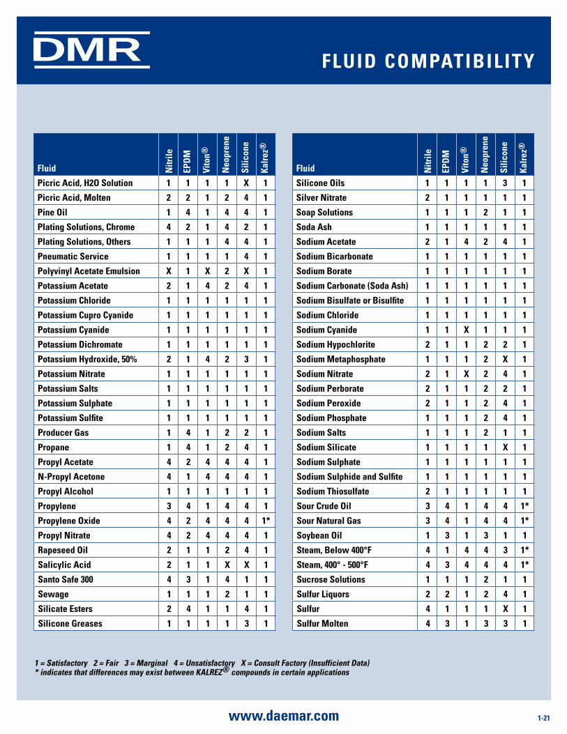
silicone oils 1 1 1 1 3 1
silver nitrate 2 1 1 1 1 1
soap solutions 1 1 1 2 1 1
soda ash 1 1 1 1 1 1
sodium acetate 2 1 4 2 4 1
sodium Bicarbonate 1 1 1 1 1 1
sodium Borate 1 1 1 1 1 1
sodium Carbonate (soda ash) 1 1 1 1 1 1
sodium Bisulfate or Bisulfite 1 1 1 1 1 1
sodium Chloride 1 1 1 1 1 1
sodium Cyanide 1 1 X 1 1 1
sodium Hypochlorite 2 1 1 2 2 1
sodium metaphosphate 1 1 1 2 X 1
sodium nitrate 2 1 X 2 4 1
sodium Perborate 2 1 1 2 2 1
sodium Peroxide 2 1 1 2 4 1
sodium Phosphate 1 1 1 2 4 1
sodium salts 1 1 1 2 1 1
sodium silicate 1 1 1 1 X 1
sodium sulphate 1 1 1 1 1 1
sodium sulphide and sulfite 1 1 1 1 1 1
sodium Thiosulfate 2 1 1 1 1 1
sour Crude oil 3 4 1 4 4 1*
sour natural gas 3 4 1 4 4 1*
soybean oil 1 3 1 3 1 1
steam, Below 400°F 4 1 4 4 3 1*
steam, 400° - 500°F 4 3 4 4 4 1*
sucrose solutions 1 1 1 2 1 1
sulfur liquors 2 2 1 2 4 1
sulfur 4 1 1 1 X 1
sulfur molten 4 3 1 3 3 1
Fluid nitr
ile
EPd
m
Vito
n®
neo
pren
e
silic
one
Kalr
ez®
Picric acid, H2o solution 1 1 1 1 X 1
Picric acid, molten 2 2 1 2 4 1
Pine oil 1 4 1 4 4 1
Plating solutions, Chrome 4 2 1 4 2 1
Plating solutions, others 1 1 1 4 4 1
Pneumatic service 1 1 1 1 4 1
Polyvinyl acetate Emulsion X 1 X 2 X 1
Potassium acetate 2 1 4 2 4 1
Potassium Chloride 1 1 1 1 1 1
Potassium Cupro Cyanide 1 1 1 1 1 1
Potassium Cyanide 1 1 1 1 1 1
Potassium dichromate 1 1 1 1 1 1
Potassium Hydroxide, 50% 2 1 4 2 3 1
Potassium nitrate 1 1 1 1 1 1
Potassium salts 1 1 1 1 1 1
Potassium sulphate 1 1 1 1 1 1
Potassium sulfite 1 1 1 1 1 1
Producer gas 1 4 1 2 2 1
Propane 1 4 1 2 4 1
Propyl acetate 4 2 4 4 4 1
n-Propyl acetone 4 1 4 4 4 1
Propyl alcohol 1 1 1 1 1 1
Propylene 3 4 1 4 4 1
Propylene oxide 4 2 4 4 4 1*
Propyl nitrate 4 2 4 4 4 1
rapeseed oil 2 1 1 2 4 1
salicylic acid 2 1 1 X X 1
santo safe 300 4 3 1 4 1 1
sewage 1 1 1 2 1 1
silicate Esters 2 4 1 1 4 1
silicone greases 1 1 1 1 3 1
Fluid ComPaTiBiliTy
1-22 www.daemar.com
DMR
Fluid nitr
ile
EPd
m
Vito
n®
neo
pren
e
silic
one
Kalr
ez®
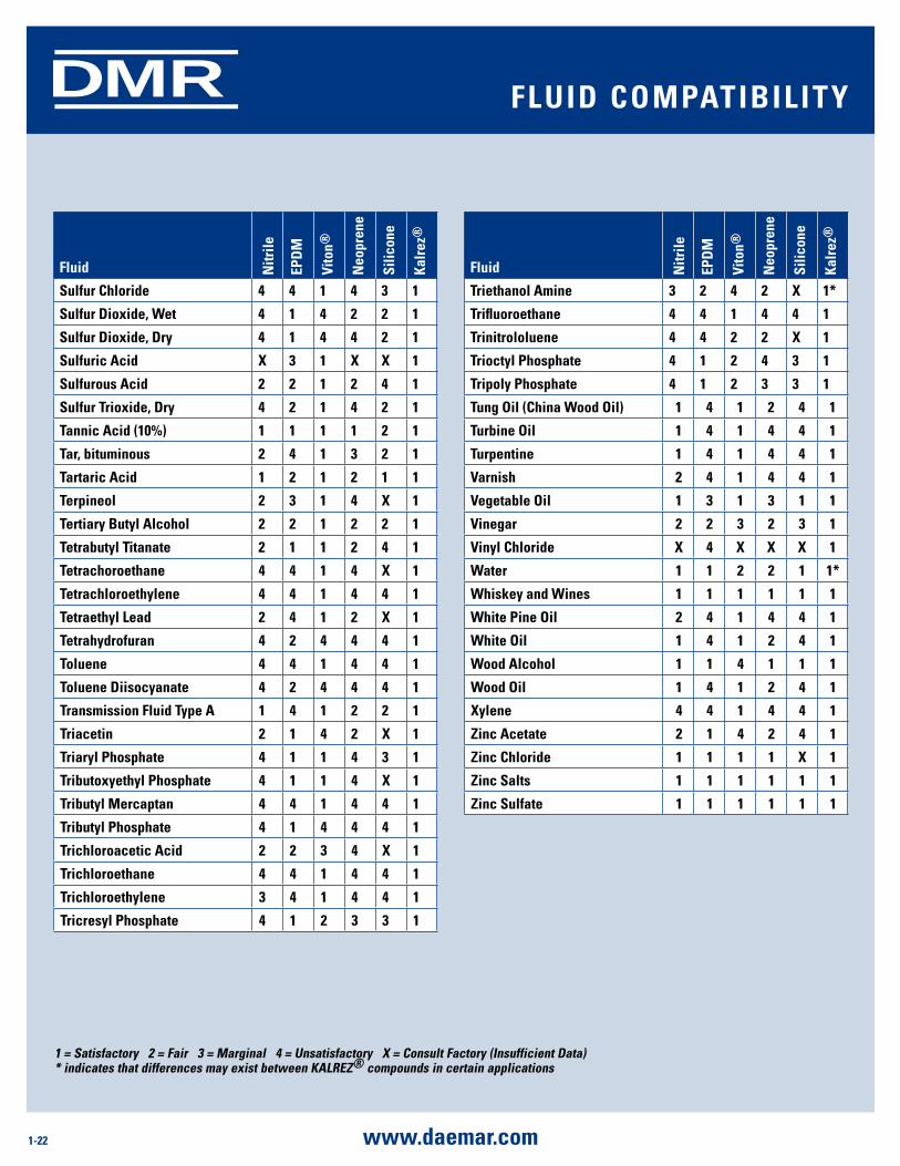
sulfur Chloride 4 4 1 4 3 1
sulfur dioxide, Wet 4 1 4 2 2 1
sulfur dioxide, dry 4 1 4 4 2 1
sulfuric acid X 3 1 X X 1
sulfurous acid 2 2 1 2 4 1
sulfur Trioxide, dry 4 2 1 4 2 1
Tannic acid (10%) 1 1 1 1 2 1
Tar, bituminous 2 4 1 3 2 1
Tartaric acid 1 2 1 2 1 1
Terpineol 2 3 1 4 X 1
Tertiary Butyl alcohol 2 2 1 2 2 1
Tetrabutyl Titanate 2 1 1 2 4 1
Tetrachoroethane 4 4 1 4 X 1
Tetrachloroethylene 4 4 1 4 4 1
Tetraethyl lead 2 4 1 2 X 1
Tetrahydrofuran 4 2 4 4 4 1
Toluene 4 4 1 4 4 1
Toluene diisocyanate 4 2 4 4 4 1
Transmission Fluid Type a 1 4 1 2 2 1
Triacetin 2 1 4 2 X 1
Triaryl Phosphate 4 1 1 4 3 1
Tributoxyethyl Phosphate 4 1 1 4 X 1
Tributyl mercaptan 4 4 1 4 4 1
Tributyl Phosphate 4 1 4 4 4 1
Trichloroacetic acid 2 2 3 4 X 1
Trichloroethane 4 4 1 4 4 1
Trichloroethylene 3 4 1 4 4 1
Tricresyl Phosphate 4 1 2 3 3 1
Fluid nitr
ile
EPd
m
Vito
n®
neo
pren
e
silic
one
Kalr
ez®
Triethanol amine 3 2 4 2 X 1*
Trifluoroethane 4 4 1 4 4 1
Trinitrololuene 4 4 2 2 X 1
Trioctyl Phosphate 4 1 2 4 3 1
Tripoly Phosphate 4 1 2 3 3 1
Tung oil (China Wood oil) 1 4 1 2 4 1
Turbine oil 1 4 1 4 4 1
Turpentine 1 4 1 4 4 1
Varnish 2 4 1 4 4 1
Vegetable oil 1 3 1 3 1 1
Vinegar 2 2 3 2 3 1
Vinyl Chloride X 4 X X X 1
Water 1 1 2 2 1 1*
Whiskey and Wines 1 1 1 1 1 1
White Pine oil 2 4 1 4 4 1
White oil 1 4 1 2 4 1
Wood alcohol 1 1 4 1 1 1
Wood oil 1 4 1 2 4 1
Xylene 4 4 1 4 4 1
Zinc acetate 2 1 4 2 4 1
Zinc Chloride 1 1 1 1 X 1
Zinc salts 1 1 1 1 1 1
Zinc sulfate 1 1 1 1 1 1
1 = satisfactory 2 = Fair 3 = marginal 4 = unsatisfactory X = Consult Factory (insufficient data)* indicates that differences may exist between KalrEZ® compounds in certain applications
Fluid ComPaTiBiliTy
1-23www.daemar.com
DMR
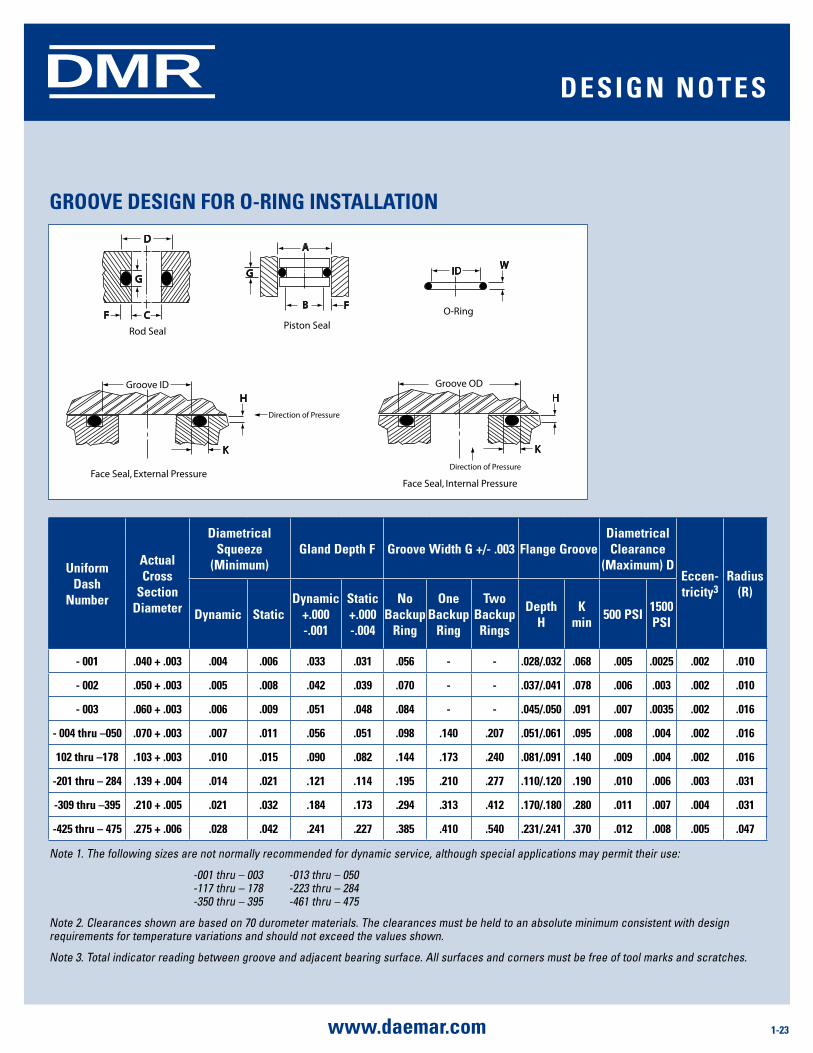
grooVE dEsign For o-ring insTallaTion
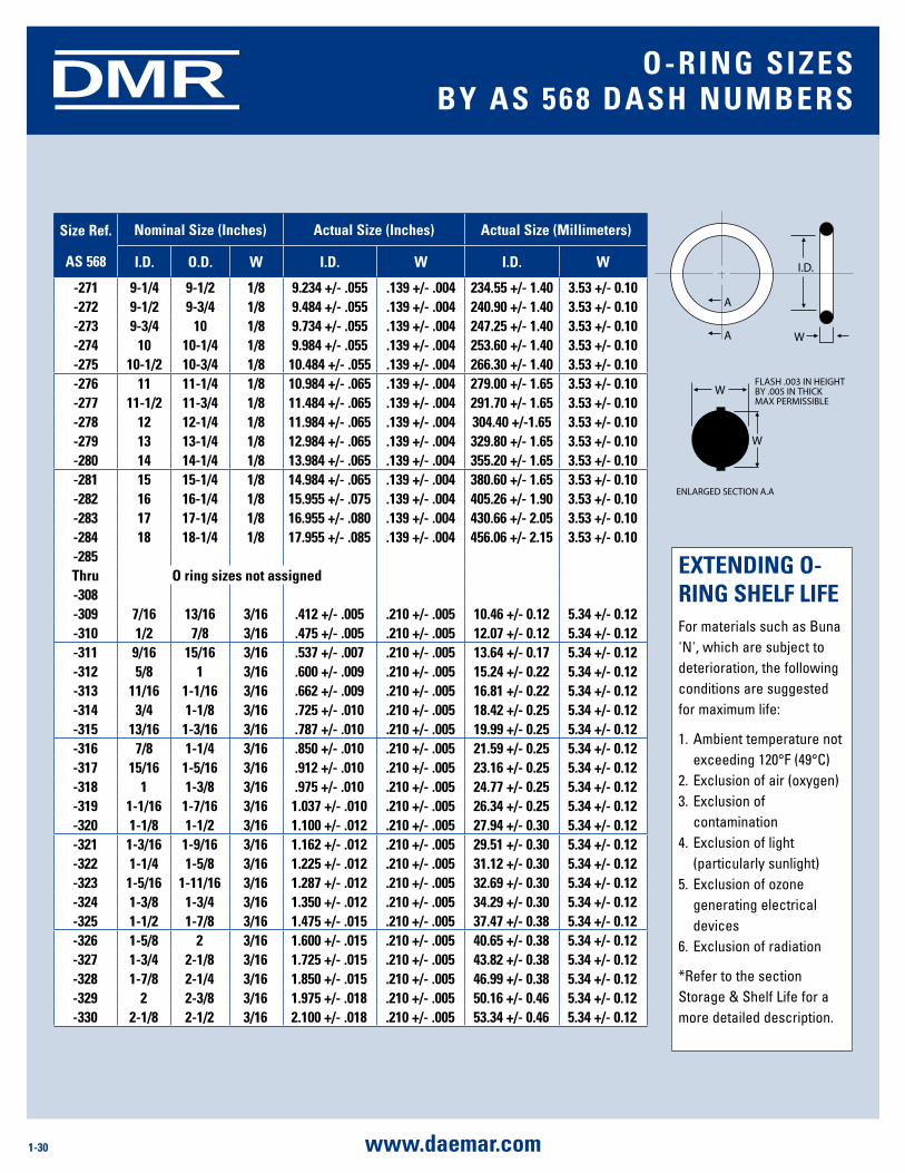
Note 1. The following sizes are not normally recommended for dynamic service, although special applications may permit their use:
-001 thru – 003 -013 thru – 050 -117 thru – 178 -223 thru – 284 -350 thru – 395 -461 thru – 475
Note 2. Clearances shown are based on 70 durometer materials. The clearances must be held to an absolute minimum consistent with design requirements for temperature variations and should not exceed the values shown.
Note 3. Total indicator reading between groove and adjacent bearing surface. All surfaces and corners must be free of tool marks and scratches.
D
G
CF
Rod Seal
B F
K
A
G
Groove IDH
Face Seal, External Pressure
Direction of Pressure
IDW
O-Ring
Piston Seal
K
Groove OD
H
Face Seal, Internal Pressure
Direction of Pressure
uniform dash
number
actual Cross
section diameter
diametrical squeeze
(minimum)gland depth F groove Width g +/- .003 Flange groove
diametrical Clearance
(maximum) dEccen- tricity3
radius (r)
dynamic staticdynamic
+.000 -.001
static +.000 -.004
no Backup
ring
one Backup
ring
Two Backup rings
depth H
K min
500 Psi1500 Psi
- 001 .040 + .003 .004 .006 .033 .031 .056 - - .028/.032 .068 .005 .0025 .002 .010
- 002 .050 + .003 .005 .008 .042 .039 .070 - - .037/.041 .078 .006 .003 .002 .010
- 003 .060 + .003 .006 .009 .051 .048 .084 - - .045/.050 .091 .007 .0035 .002 .016
- 004 thru –050 .070 + .003 .007 .011 .056 .051 .098 .140 .207 .051/.061 .095 .008 .004 .002 .016
102 thru –178 .103 + .003 .010 .015 .090 .082 .144 .173 .240 .081/.091 .140 .009 .004 .002 .016
-201 thru – 284 .139 + .004 .014 .021 .121 .114 .195 .210 .277 .110/.120 .190 .010 .006 .003 .031
-309 thru –395 .210 + .005 .021 .032 .184 .173 .294 .313 .412 .170/.180 .280 .011 .007 .004 .031
-425 thru – 475 .275 + .006 .028 .042 .241 .227 .385 .410 .540 .231/.241 .370 .012 .008 .005 .047
dEsign noTEs
1-24 www.daemar.com
DMR
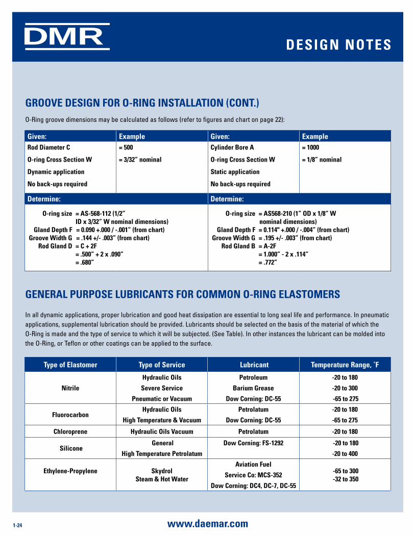
gEnEral PurPosE luBriCanTs For Common o-ring ElasTomErs
O-Ring groove dimensions may be calculated as follows (refer to figures and chart on page 22):
given: Example given: Examplerod diameter C = 500 Cylinder Bore a = 1000
o-ring Cross section W = 3/32” nominal o-ring Cross section W = 1/8” nominal
dynamic application static application
no back-ups required no back-ups required
determine: determine:
o-ring size = as-568-112 (1/2” id x 3/32” W nominal dimensions) gland depth F = 0.090 +.000 / -.001” (from chart) groove Width g = .144 +/- .003” (from chart) rod gland d = C + 2F = .500” + 2 x .090” = .680”
o-ring size = as568-210 (1” od x 1/8” W nominal dimensions) gland depth F = 0.114" +.000 / -.004” (from chart) groove Width g = .195 +/- .003” (from chart) rod gland B = a-2F = 1.000” - 2 x .114” = .772”
In all dynamic applications, proper lubrication and good heat dissipation are essential to long seal life and performance. In pneumatic applications, supplemental lubrication should be provided. Lubricants should be selected on the basis of the material of which the O-Ring is made and the type of service to which it will be subjected. (See Table). In other instances the lubricant can be molded into the O-Ring, or Teflon or other coatings can be applied to the surface.
grooVE dEsign For o-ring insTallaTion (ConT.)
Type of Elastomer Type of service lubricant Temperature range, ˚F
nitrile
Hydraulic oils Petroleum -20 to 180
severe service Barium grease -20 to 300
Pneumatic or Vacuum dow Corning: dC-55 -65 to 275
FluorocarbonHydraulic oils Petrolatum -20 to 180
High Temperature & Vacuum dow Corning: dC-55 -65 to 275
Chloroprene Hydraulic oils Vacuum Petrolatum -20 to 180
silicone general dow Corning: Fs-1292 -20 to 180
High Temperature Petrolatum -20 to 400
Ethylene-Propylene
skydrolsteam & Hot Water
aviation Fuel -65 to 300 -32 to 350
service Co: mCs-352
dow Corning: dC4, dC-7, dC-55
dEsign noTEs
1-25www.daemar.com
DMR
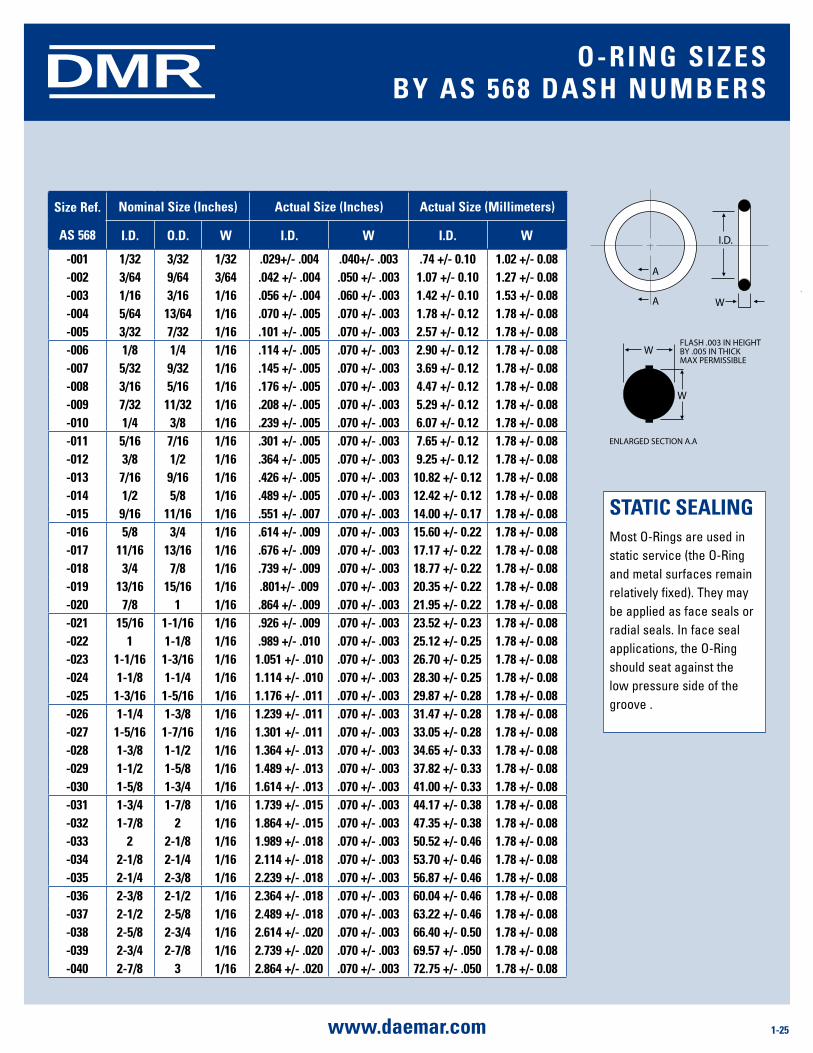
size ref.
as 568
nominal size (inches) actual size (inches) actual size (millimeters)
i.d. o.d. W i.d. W i.d. W
-001 1/32 3/32 1/32 .029+/- .004 .040+/- .003 .74 +/- 0.10 1.02 +/- 0.08-002 3/64 9/64 3/64 .042 +/- .004 .050 +/- .003 1.07 +/- 0.10 1.27 +/- 0.08-003 1/16 3/16 1/16 .056 +/- .004 .060 +/- .003 1.42 +/- 0.10 1.53 +/- 0.08-004 5/64 13/64 1/16 .070 +/- .005 .070 +/- .003 1.78 +/- 0.12 1.78 +/- 0.08-005 3/32 7/32 1/16 .101 +/- .005 .070 +/- .003 2.57 +/- 0.12 1.78 +/- 0.08-006 1/8 1/4 1/16 .114 +/- .005 .070 +/- .003 2.90 +/- 0.12 1.78 +/- 0.08-007 5/32 9/32 1/16 .145 +/- .005 .070 +/- .003 3.69 +/- 0.12 1.78 +/- 0.08-008 3/16 5/16 1/16 .176 +/- .005 .070 +/- .003 4.47 +/- 0.12 1.78 +/- 0.08-009 7/32 11/32 1/16 .208 +/- .005 .070 +/- .003 5.29 +/- 0.12 1.78 +/- 0.08-010 1/4 3/8 1/16 .239 +/- .005 .070 +/- .003 6.07 +/- 0.12 1.78 +/- 0.08-011 5/16 7/16 1/16 .301 +/- .005 .070 +/- .003 7.65 +/- 0.12 1.78 +/- 0.08-012 3/8 1/2 1/16 .364 +/- .005 .070 +/- .003 9.25 +/- 0.12 1.78 +/- 0.08-013 7/16 9/16 1/16 .426 +/- .005 .070 +/- .003 10.82 +/- 0.12 1.78 +/- 0.08-014 1/2 5/8 1/16 .489 +/- .005 .070 +/- .003 12.42 +/- 0.12 1.78 +/- 0.08-015 9/16 11/16 1/16 .551 +/- .007 .070 +/- .003 14.00 +/- 0.17 1.78 +/- 0.08-016 5/8 3/4 1/16 .614 +/- .009 .070 +/- .003 15.60 +/- 0.22 1.78 +/- 0.08-017 11/16 13/16 1/16 .676 +/- .009 .070 +/- .003 17.17 +/- 0.22 1.78 +/- 0.08-018 3/4 7/8 1/16 .739 +/- .009 .070 +/- .003 18.77 +/- 0.22 1.78 +/- 0.08-019 13/16 15/16 1/16 .801+/- .009 .070 +/- .003 20.35 +/- 0.22 1.78 +/- 0.08-020 7/8 1 1/16 .864 +/- .009 .070 +/- .003 21.95 +/- 0.22 1.78 +/- 0.08-021 15/16 1-1/16 1/16 .926 +/- .009 .070 +/- .003 23.52 +/- 0.23 1.78 +/- 0.08-022 1 1-1/8 1/16 .989 +/- .010 .070 +/- .003 25.12 +/- 0.25 1.78 +/- 0.08-023 1-1/16 1-3/16 1/16 1.051 +/- .010 .070 +/- .003 26.70 +/- 0.25 1.78 +/- 0.08-024 1-1/8 1-1/4 1/16 1.114 +/- .010 .070 +/- .003 28.30 +/- 0.25 1.78 +/- 0.08-025 1-3/16 1-5/16 1/16 1.176 +/- .011 .070 +/- .003 29.87 +/- 0.28 1.78 +/- 0.08-026 1-1/4 1-3/8 1/16 1.239 +/- .011 .070 +/- .003 31.47 +/- 0.28 1.78 +/- 0.08-027 1-5/16 1-7/16 1/16 1.301 +/- .011 .070 +/- .003 33.05 +/- 0.28 1.78 +/- 0.08-028 1-3/8 1-1/2 1/16 1.364 +/- .013 .070 +/- .003 34.65 +/- 0.33 1.78 +/- 0.08-029 1-1/2 1-5/8 1/16 1.489 +/- .013 .070 +/- .003 37.82 +/- 0.33 1.78 +/- 0.08-030 1-5/8 1-3/4 1/16 1.614 +/- .013 .070 +/- .003 41.00 +/- 0.33 1.78 +/- 0.08-031 1-3/4 1-7/8 1/16 1.739 +/- .015 .070 +/- .003 44.17 +/- 0.38 1.78 +/- 0.08-032 1-7/8 2 1/16 1.864 +/- .015 .070 +/- .003 47.35 +/- 0.38 1.78 +/- 0.08-033 2 2-1/8 1/16 1.989 +/- .018 .070 +/- .003 50.52 +/- 0.46 1.78 +/- 0.08-034 2-1/8 2-1/4 1/16 2.114 +/- .018 .070 +/- .003 53.70 +/- 0.46 1.78 +/- 0.08-035 2-1/4 2-3/8 1/16 2.239 +/- .018 .070 +/- .003 56.87 +/- 0.46 1.78 +/- 0.08-036 2-3/8 2-1/2 1/16 2.364 +/- .018 .070 +/- .003 60.04 +/- 0.46 1.78 +/- 0.08-037 2-1/2 2-5/8 1/16 2.489 +/- .018 .070 +/- .003 63.22 +/- 0.46 1.78 +/- 0.08-038 2-5/8 2-3/4 1/16 2.614 +/- .020 .070 +/- .003 66.40 +/- 0.50 1.78 +/- 0.08-039 2-3/4 2-7/8 1/16 2.739 +/- .020 .070 +/- .003 69.57 +/- .050 1.78 +/- 0.08-040 2-7/8 3 1/16 2.864 +/- .020 .070 +/- .003 72.75 +/- .050 1.78 +/- 0.08
A
A W
W
W
I.D.
FLASH .003 IN HEIGHTBY .005 IN THICK MAX PERMISSIBLE
ENLARGED SECTION A.A
sTaTiC sEalingMost O-Rings are used in static service (the O-Ring and metal surfaces remain relatively fixed). They may be applied as face seals or radial seals. In face seal applications, the O-Ring should seat against the low pressure side of the groove .
o-ring siZEsBy as 568 dasH numBErs
1-26 www.daemar.com
DMR
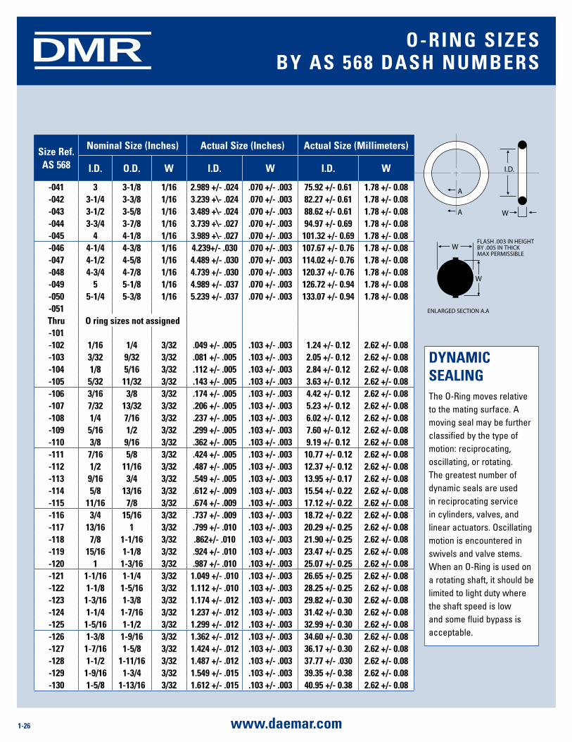
size ref. as 568
nominal size (inches) actual size (inches) actual size (millimeters)
i.d. o.d. W i.d. W i.d. W
-041 3 3-1/8 1/16 2.989 +/- .024 .070 +/- .003 75.92 +/- 0.61 1.78 +/- 0.08-042 3-1/4 3-3/8 1/16 3.239 +\- .024 .070 +/- .003 82.27 +/- 0.61 1.78 +/- 0.08-043 3-1/2 3-5/8 1/16 3.489 +\- .024 .070 +/- .003 88.62 +/- 0.61 1.78 +/- 0.08-044 3-3/4 3-7/8 1/16 3.739 +\- .027 .070 +/- .003 94.97 +/- 0.69 1.78 +/- 0.08-045 4 4-1/8 1/16 3.989 +\- .027 .070 +/- .003 101.32 +/- 0.69 1.78 +/- 0.08-046 4-1/4 4-3/8 1/16 4.239+/- .030 .070 +/- .003 107.67 +/- 0.76 1.78 +/- 0.08-047 4-1/2 4-5/8 1/16 4.489 +/- .030 .070 +/- .003 114.02 +/- 0.76 1.78 +/- 0.08-048 4-3/4 4-7/8 1/16 4.739 +/- .030 .070 +/- .003 120.37 +/- 0.76 1.78 +/- 0.08-049 5 5-1/8 1/16 4.989 +/- .037 .070 +/- .003 126.72 +/- 0.94 1.78 +/- 0.08-050 5-1/4 5-3/8 1/16 5.239 +/- .037 .070 +/- .003 133.07 +/- 0.94 1.78 +/- 0.08-051Thru o ring sizes not assigned-101-102 1/16 1/4 3/32 .049 +/- .005 .103 +/- .003 1.24 +/- 0.12 2.62 +/- 0.08-103 3/32 9/32 3/32 .081 +/- .005 .103 +/- .003 2.05 +/- 0.12 2.62 +/- 0.08-104 1/8 5/16 3/32 .112 +/- .005 .103 +/- .003 2.84 +/- 0.12 2.62 +/- 0.08-105 5/32 11/32 3/32 .143 +/- .005 .103 +/- .003 3.63 +/- 0.12 2.62 +/- 0.08-106 3/16 3/8 3/32 .174 +/- .005 .103 +/- .003 4.42 +/- 0.12 2.62 +/- 0.08-107 7/32 13/32 3/32 .206 +/- .005 .103 +/- .003 5.23 +/- 0.12 2.62 +/- 0.08-108 1/4 7/16 3/32 .237 +/- .005 .103 +/- .003 6.02 +/- 0.12 2.62 +/- 0.08-109 5/16 1/2 3/32 .299 +/- .005 .103 +/- .003 7.60 +/- 0.12 2.62 +/- 0.08-110 3/8 9/16 3/32 .362 +/- .005 .103 +/- .003 9.19 +/- 0.12 2.62 +/- 0.08-111 7/16 5/8 3/32 .424 +/- .005 .103 +/- .003 10.77 +/- 0.12 2.62 +/- 0.08-112 1/2 11/16 3/32 .487 +/- .005 .103 +/- .003 12.37 +/- 0.12 2.62 +/- 0.08-113 9/16 3/4 3/32 .549 +/- .005 .103 +/- .003 13.95 +/- 0.17 2.62 +/- 0.08-114 5/8 13/16 3/32 .612 +/- .009 .103 +/- .003 15.54 +/- 0.22 2.62 +/- 0.08-115 11/16 7/8 3/32 .674 +/- .009 .103 +/- .003 17.12 +/- 0.22 2.62 +/- 0.08-116 3/4 15/16 3/32 .737 +/- .009 .103 +/- .003 18.72 +/- 0.22 2.62 +/- 0.08-117 13/16 1 3/32 .799 +/- .010 .103 +/- .003 20.29 +/- 0.25 2.62 +/- 0.08-118 7/8 1-1/16 3/32 .862+/- .010 .103 +/- .003 21.90 +/- 0.25 2.62 +/- 0.08-119 15/16 1-1/8 3/32 .924 +/- .010 .103 +/- .003 23.47 +/- 0.25 2.62 +/- 0.08-120 1 1-3/16 3/32 .987 +/- .010 .103 +/- .003 25.07 +/- 0.25 2.62 +/- 0.08-121 1-1/16 1-1/4 3/32 1.049 +/- .010 .103 +/- .003 26.65 +/- 0.25 2.62 +/- 0.08-122 1-1/8 1-5/16 3/32 1.112 +/- .010 .103 +/- .003 28.25 +/- 0.25 2.62 +/- 0.08-123 1-3/16 1-3/8 3/32 1.174 +/- .012 .103 +/- .003 29.82 +/- 0.30 2.62 +/- 0.08-124 1-1/4 1-7/16 3/32 1.237 +/- .012 .103 +/- .003 31.42 +/- 0.30 2.62 +/- 0.08-125 1-5/16 1-1/2 3/32 1.299 +/- .012 .103 +/- .003 32.99 +/- 0.30 2.62 +/- 0.08-126 1-3/8 1-9/16 3/32 1.362 +/- .012 .103 +/- .003 34.60 +/- 0.30 2.62 +/- 0.08-127 1-7/16 1-5/8 3/32 1.424 +/- .012 .103 +/- .003 36.17 +/- 0.30 2.62 +/- 0.08-128 1-1/2 1-11/16 3/32 1.487 +/- .012 .103 +/- .003 37.77 +/- .030 2.62 +/- 0.08-129 1-9/16 1-3/4 3/32 1.549 +/- .015 .103 +/- .003 39.35 +/- 0.38 2.62 +/- 0.08-130 1-5/8 1-13/16 3/32 1.612 +/- .015 .103 +/- .003 40.95 +/- 0.38 2.62 +/- 0.08
dynamiC sEalingThe O-Ring moves relative to the mating surface. A moving seal may be further classified by the type of motion: reciprocating, oscillating, or rotating. The greatest number of dynamic seals are used in reciprocating service in cylinders, valves, and linear actuators. Oscillating motion is encountered in swivels and valve stems. When an O-Ring is used on a rotating shaft, it should be limited to light duty where the shaft speed is low and some fluid bypass is acceptable.
o-ring siZEsBy as 568 dasH numBErs
A
A W
W
W
I.D.
FLASH .003 IN HEIGHTBY .005 IN THICK MAX PERMISSIBLE
ENLARGED SECTION A.A
1-27www.daemar.com
DMR
size ref. as 568
nominal size (inches) actual size (inches) actual size (millimeters)
i.d. o.d. W i.d. W i.d. W
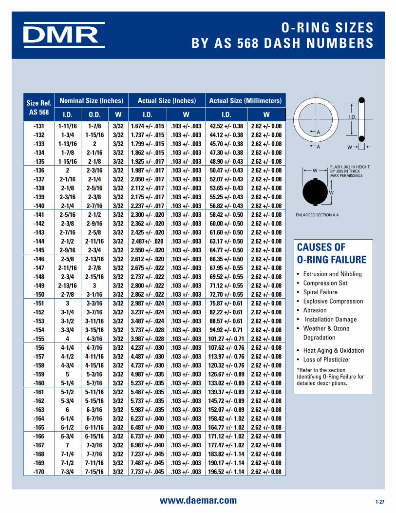
-131 1-11/16 1-7/8 3/32 1.674 +/- .015 .103 +/- .003 42.52 +/- 0.38 2.62 +/- 0.08-132 1-3/4 1-15/16 3/32 1.737 +/- .015 .103 +/- .003 44.12 +/- 0.38 2.62 +/- 0.08-133 1-13/16 2 3/32 1.799 +/- .015 .103 +/- .003 45.70 +/- 0.38 2.62 +/- 0.08-134 1-7/8 2-1/16 3/32 1.862 +/- .015 .103 +/- .003 47.30 +/- 0.38 2.62 +/- 0.08-135 1-15/16 2-1/8 3/32 1.925 +/- .017 .103 +/- .003 48.90 +/- 0.43 2.62 +/- 0.08-136 2 2-3/16 3/32 1.987 +/- .017 .103 +/- .003 50.47 +/- 0.43 2.62 +/- 0.08-137 2-1/16 2-1/4 3/32 2.050 +/- .017 .103 +/- .003 52.07 +/- 0.43 2.62 +/- 0.08-138 2-1/8 2-5/16 3/32 2.112 +/- .017 .103 +/- .003 53.65 +/- 0.43 2.62 +/- 0.08-139 2-3/16 2-3/8 3/32 2.175 +/- .017 .103 +/- .003 55.25 +/- 0.43 2.62 +/- 0.08-140 2-1/4 2-7/16 3/32 2.237 +/- .017 .103 +/- .003 56.82 +/- 0.43 2.62 +/- 0.08-141 2-5/16 2-1/2 3/32 2.300 +/- .020 .103 +/- .003 58.42 +/- 0.50 2.62 +/- 0.08-142 2-3/8 2-9/16 3/32 2.362 +/- .020 .103 +/- .003 60.00 +/- 0.50 2.62 +/- 0.08-143 2-7/16 2-5/8 3/32 2.425 +/- .020 .103 +/- .003 61.60 +/- 0.50 2.62 +/- 0.08-144 2-1/2 2-11/16 3/32 2.487+/- .020 .103 +/- .003 63.17 +/- 0.50 2.62 +/- 0.08-145 2-9/16 2-3/4 3/32 2.550 +/- .020 .103 +/- .003 64.77 +/- 0.50 2.62 +/- 0.08-146 2-5/8 2-13/16 3/32 2.612 +/- .020 .103 +/- .003 66.35 +/- 0.50 2.62 +/- 0.08-147 2-11/16 2-7/8 3/32 2.675 +/- .022 .103 +/- .003 67.95 +/- 0.55 2.62 +/- 0.08-148 2-3/4 2-15/16 3/32 2.737 +/- .022 .103 +/- .003 69.52 +/- 0.55 2.62 +/- 0.08-149 2-13/16 3 3/32 2.800 +/- .022 .103 +/- .003 71.12 +/- 0.55 2.62 +/- 0.08-150 2-7/8 3-1/16 3/32 2.862 +/- .022 .103 +/- .003 72.70 +/- 0.55 2.62 +/- 0.08-151 3 3-3/16 3/32 2.987 +/- .024 .103 +/- .003 75.87 +/- 0.61 2.62 +/- 0.08-152 3-1/4 3-7/16 3/32 3.237 +/- .024 .103 +/- .003 82.22 +/- 0.61 2.62 +/- 0.08-153 3-1/2 3-11/16 3/32 3.487 +/- .024 .103 +/- .003 88.57 +/- 0.61 2.62 +/- 0.08-154 3-3/4 3-15/16 3/32 3.737 +/- .028 .103 +/- .003 94.92 +/- 0.71 2.62 +/- 0.08-155 4 4-3/16 3/32 3.987 +/- .028 .103 +/- .003 101.27 +/- 0.71 2.62 +/- 0.08-156 4-1/4 4-7/16 3/32 4.237 +/- .030 .103 +/- .003 107.62 +/- 0.76 2.62 +/- 0.08-157 4-1/2 4-11/16 3/32 4.487 +/- .030 .103 +/- .003 113.97 +/- 0.76 2.62 +/- 0.08-158 4-3/4 4-15/16 3/32 4.737 +/- .030 .103 +/- .003 120.32 +/- 0.76 2.62 +/- 0.08-159 5 5-3/16 3/32 4.987 +/- .035 .103 +/- .003 126.67 +/- 0.89 2.62 +/- 0.08-160 5-1/4 5-7/16 3/32 5.237 +/- .035 .103 +/- .003 133.02 +/- 0.89 2.62 +/- 0.08-161 5-1/2 5-11/16 3/32 5.487 +/- .035 .103 +/- .003 139.37 +/- 0.89 2.62 +/- 0.08-162 5-3/4 5-15/16 3/32 5.737 +/- .035 .103 +/- .003 145.72 +/- 0.89 2.62 +/- 0.08-163 6 6-3/16 3/32 5.987 +/- .035 .103 +/- .003 152.07 +/- 0.89 2.62 +/- 0.08-164 6-1/4 6-7/16 3/32 6.237 +/- .040 .103 +/- .003 158.42 +/- 1.02 2.62 +/- 0.08-165 6-1/2 6-11/16 3/32 6.487 +/- .040 .103 +/- .003 164.77 +/- 1.02 2.62 +/- 0.08-166 6-3/4 6-15/16 3/32 6.737 +/- .040 .103 +/- .003 171.12 +/- 1.02 2.62 +/- 0.08-167 7 7-3/16 3/32 6.987 +/- .040 .103 +/- .003 177.47 +/- 1.02 2.62 +/- 0.08-168 7-1/4 7-7/16 3/32 7.237 +/- .045 .103 +/- .003 183.82 +/- 1.14 2.62 +/- 0.08-169 7-1/2 7-11/16 3/32 7.487 +/- .045 .103 +/- .003 190.17 +/- 1.14 2.62 +/- 0.08-170 7-3/4 7-15/16 3/32 7.737 +/- .045 .103 +/- .003 196.52 +/- 1.14 2.62 +/- 0.08
CausEs oF o-ring FailurE• ExtrusionandNibbling • CompressionSet • SpiralFailure • ExplosiveCompression • Abrasion • InstallationDamage • Weather&Ozone Degradation
• HeatAging&Oxidation • LossofPlasticizer
*Refer to the section Identifying O-Ring Failure for detailed descriptions.
o-ring siZEsBy as 568 dasH numBErs
A
A W
W
W
I.D.
FLASH .003 IN HEIGHTBY .005 IN THICK MAX PERMISSIBLE
ENLARGED SECTION A.A
1-28 www.daemar.com
DMR
size ref.
as 568
nominal size (inches) actual size (inches) actual size (millimeters)
i.d. o.d. W i.d. W i.d. W
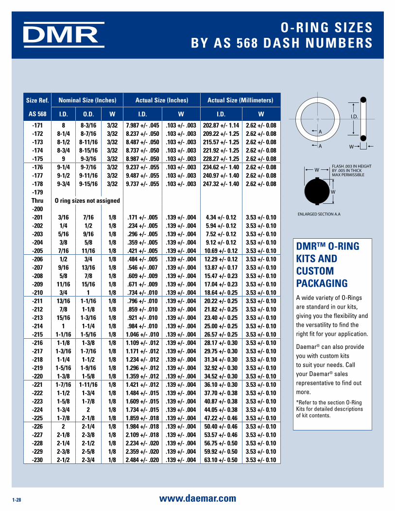
-171 8 8-3/16 3/32 7.987 +/- .045 .103 +/- .003 202.87 +/- 1.14 2.62 +/- 0.08-172 8-1/4 8-7/16 3/32 8.237 +/- .050 .103 +/- .003 209.22 +/- 1.25 2.62 +/- 0.08-173 8-1/2 8-11/16 3/32 8.487 +/- .050 .103 +/- .003 215.57 +/- 1.25 2.62 +/- 0.08-174 8-3/4 8-15/16 3/32 8.737 +/- .050 .103 +/- .003 221.92 +/- 1.25 2.62 +/- 0.08-175 9 9-3/16 3/32 8.987 +/- .050 .103 +/- .003 228.27 +/- 1.25 2.62 +/- 0.08-176 9-1/4 9-7/16 3/32 9.237 +/- .055 .103 +/- .003 234.62 +/- 1.40 2.62 +/- 0.08-177 9-1/2 9-11/16 3/32 9.487 +/- .055 .103 +/- .003 240.97 +/- 1.40 2.62 +/- 0.08-178 9-3/4 9-15/16 3/32 9.737 +/- .055 .103 +/- .003 247.32 +/- 1.40 2.62 +/- 0.08-179Thru o ring sizes not assigned-200-201 3/16 7/16 1/8 .171 +/- .005 .139 +/- .004 4.34 +/- 0.12 3.53 +/- 0.10-202 1/4 1/2 1/8 .234 +/- .005 .139 +/- .004 5.94 +/- 0.12 3.53 +/- 0.10-203 5/16 9/16 1/8 .296 +/- .005 .139 +/- .004 7.52 +/- 0.12 3.53 +/- 0.10-204 3/8 5/8 1/8 .359 +/- .005 .139 +/- .004 9.12 +/- 0.12 3.53 +/- 0.10-205 7/16 11/16 1/8 .421 +/- .005 .139 +/- .004 10.69 +/- 0.12 3.53 +/- 0.10-206 1/2 3/4 1/8 .484 +/- .005 .139 +/- .004 12.29 +/- 0.12 3.53 +/- 0.10-207 9/16 13/16 1/8 .546 +/- .007 .139 +/- .004 13.87 +/- 0.17 3.53 +/- 0.10-208 5/8 7/8 1/8 .609 +/- .009 .139 +/- .004 15.47 +/- 0.23 3.53 +/- 0.10-209 11/16 15/16 1/8 .671 +/- .009 .139 +/- .004 17.04 +/- 0.23 3.53 +/- 0.10-210 3/4 1 1/8 .734 +/- .010 .139 +/- .004 18.64 +/- 0.25 3.53 +/- 0.10-211 13/16 1-1/16 1/8 .796 +/- .010 .139 +/- .004 20.22 +/- 0.25 3.53 +/- 0.10-212 7/8 1-1/8 1/8 .859 +/- .010 .139 +/- .004 21.82 +/- 0.25 3.53 +/- 0.10-213 15/16 1-3/16 1/8 .921 +/- .010 .139 +/- .004 23.40 +/- 0.25 3.53 +/- 0.10-214 1 1-1/4 1/8 .984 +/- .010 .139 +/- .004 25.00 +/- 0.25 3.53 +/- 0.10-215 1-1/16 1-5/16 1/8 1.046 +/- .010 .139 +/- .004 26.57 +/- 0.25 3.53 +/- 0.10-216 1-1/8 1-3/8 1/8 1.109 +/- .012 .139 +/- .004 28.17 +/- 0.30 3.53 +/- 0.10-217 1-3/16 1-7/16 1/8 1.171 +/- .012 .139 +/- .004 29.75 +/- 0.30 3.53 +/- 0.10-218 1-1/4 1-1/2 1/8 1.234 +/- .012 .139 +/- .004 31.34 +/- 0.30 3.53 +/- 0.10-219 1-5/16 1-9/16 1/8 1.296 +/- .012 .139 +/- .004 32.92 +/- 0.30 3.53 +/- 0.10-220 1-3/8 1-5/8 1/8 1.359 +/- .012 .139 +/- .004 34.52 +/- 0.30 3.53 +/- 0.10-221 1-7/16 1-11/16 1/8 1.421 +/- .012 .139 +/- .004 36.10 +/- 0.30 3.53 +/- 0.10-222 1-1/2 1-3/4 1/8 1.484 +/- .015 .139 +/- .004 37.70 +/- 0.38 3.53 +/- 0.10-223 1-5/8 1-7/8 1/8 1.609 +/- .015 .139 +/- .004 40.87 +/- 0.38 3.53 +/- 0.10-224 1-3/4 2 1/8 1.734 +/- .015 .139 +/- .004 44.05 +/- 0.38 3.53 +/- 0.10-225 1-7/8 2-1/8 1/8 1.859 +/- .018 .139 +/- .004 47.22 +/- 0.46 3.53 +/- 0.10-226 2 2-1/4 1/8 1.984 +/- .018 .139 +/- .004 50.40 +/- 0.46 3.53 +/- 0.10-227 2-1/8 2-3/8 1/8 2.109 +/- .018 .139 +/- .004 53.57 +/- 0.46 3.53 +/- 0.10-228 2-1/4 2-1/2 1/8 2.234 +/- .020 .139 +/- .004 56.75 +/- 0.50 3.53 +/- 0.10-229 2-3/8 2-5/8 1/8 2.359 +/- .020 .139 +/- .004 59.92 +/- 0.50 3.53 +/- 0.10-230 2-1/2 2-3/4 1/8 2.484 +/- .020 .139 +/- .004 63.10 +/- 0.50 3.53 +/- 0.10
dmr™ o-ring KiTs and CusTom PaCKagingA wide variety of O-Rings are standard in our kits, giving you the flexibility and the versatility to find the right fit for your application.
Daemar® can also provide you with custom kits to suit your needs. Call your Daemar® sales representative to find out more.
*Refer to the section O-Ring Kits for detailed descriptions of kit contents.
o-ring siZEsBy as 568 dasH numBErs
A
A W
W
W
I.D.
FLASH .003 IN HEIGHTBY .005 IN THICK MAX PERMISSIBLE
ENLARGED SECTION A.A
1-29www.daemar.com
DMR
size ref.
as 568
nominal size (inches) actual size (inches) actual size (millimeters)
i.d. o.d. W i.d. W i.d. W
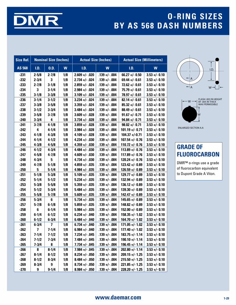
-231 2-5/8 2-7/8 1/8 2.609 +/- .020 .139 +/- .004 66.27 +/- 0.50 3.53 +/- 0.10-232 2-3/4 3 1/8 2.734 +/- .024 .139 +/- .004 69.44 +/- 0.61 3.53 +/- 0.10-233 2-7/8 3-1/8 1/8 2.859 +/- .024 .139 +/- .004 72.62 +/- 0.61 3.53 +/- 0.10-234 3 3-1/4 1/8 2.984 +/- .024 .139 +/- .004 75.79 +/- 0.61 3.53 +/- 0.10-235 3-1/8 3-3/8 1/8 3.109 +/- .024 .139 +/- .004 78.97 +/- 0.61 3.53 +/- 0.10-236 3-1/4 3-1/2 1/8 3.234 +/- .024 .139 +/- .004 82.14 +/- 0.61 3.53 +/- 0.10-237 3-3/8 3-5/8 1/8 3.359 +/- .024 .139 +/- .004 85.32 +/- 0.61 3.53 +/- 0.10-238 3-1/2 3-3/4 1/8 3.484 +/- .024 .139 +/- .004 88.49 +/- 0.61 3.53 +/- 0.10-239 3-5/8 3-7/8 1/8 3.609 +/- .028 .139 +/- .004 91.67 +/- 0.71 3.53 +/- 0.10-240 3-3/4 4 1/8 3.734 +/- .028 .139 +/- .004 94.84 +/- 0.71 3.53 +/- 0.10-241 3-7/8 4-1/8 1/8 3.859 +/- .028 .139 +/- .004 98.02 +/- 0.71 3.53 +/- 0.10-242 4 4-1/4 1/8 3.984 +/- .028 .139 +/- .004 101.19 +/- 0.71 3.53 +/- 0.10-243 4-1/8 4-3/8 1/8 4.109 +/- .028 .139 +/- .004 104.37 +/-0.71 3.53 +/- 0.10-244 4-1/4 4-1/2 1/8 4.234 +/- .030 .139 +/- .004 107.54 +/- 0.76 3.53 +/- 0.10-245 4-3/8 4-5/8 1/8 4.359 +/- .030 .139 +/- .004 110.72 +/- 0.76 3.53 +/- 0.10-246 4-1/2 4-3/4 1/8 4.484 +/- .030 .139 +/- .004 113.89 +/- 0.76 3.53 +/- 0.10-247 4-5/8 4-7/8 1/8 4.609 +/- .030 .139 +/- .004 117.89 +/- 0.76 3.53 +/- 0.10-248 4-3/4 5 1/8 4.734 +/- .030 .139 +/- .004 120.24 +/- 0.76 3.53 +/- 0.10-249 4-7/8 5-1/8 1/8 4.859 +/- .035 .139 +/- .004 123.42 +/- 0.89 3.53 +/- 0.10-250 5 5-1/4 1/8 4.984 +/- .035 .139 +/- .004 126.59 +/- 0.89 3.53 +/- 0.10-251 5-1/8 5-3/8 1/8 5.109 +/- .035 .139 +/- .004 129.77 +/- 0.89 3.53 +/- 0.10-252 5-1/4 5-1/2 1/8 5.234 +/- .035 .139 +/- .004 132.94 +/- 0.89 3.53 +/- 0.10-253 5-3/8 5-5/8 1/8 5.359 +/- .035 .139 +/- .004 136.12 +/- 0.89 3.53 +/- 0.10-254 5-1/2 5-3/4 1/8 5.484 +/- .035 .139 +/- .004 139.30 +/- 0.89 3.53 +/- 0.10-255 5-5/8 5-7/8 1/8 5.609 +/- .035 .139 +/- .004 142.47 +/- 0.89 3.53 +/- 0.10-256 5-3/4 6 1/8 5.734 +/- .035 .139 +/- .004 145.65 +/- 0.89 3.53 +/- 0.10-257 5-7/8 6-1/8 1/8 5.859 +/- .035 .139 +/- .004 148.82 +/- 0.89 3.53 +/- 0.10-258 6 6-1/4 1/8 5.984 +/- .035 .139 +/- .004 152.00 +/- 0.89 3.53 +/- 0.10-259 6-1/4 6-1/2 1/8 6.234 +/- .040 .139 +/- .004 158.35 +/- 1.02 3.53 +/- 0.10-260 6-1/2 6-3/4 1/8 6.484 +/- .040 .139 +/- .004 164.70 +/- 1.02 3.53 +/- 0.10-261 6-3/4 7 1/8 6.734 +/- .040 .139 +/- .004 171.05 +/- 1.02 3.53 +/- 0.10-262 7 7-1/4 1/8 6.984 +/- .040 .139 +/- .004 177.40 +/- 1.02 3.53 +/- 0.10-263 7-1/4 7-1/2 1/8 7.234 +/- .045 .139 +/- .004 183.75 +/- 1.14 3.53 +/- 0.10-264 7-1/2 7-3/4 1/8 7.484 +/- .045 .139 +/- .004 190.10 +/- 1.14 3.53 +/- 0.10-265 7-3/4 8 1/8 7.734 +/- .045 .139 +/- .004 196.45 +/- 1.14 3.53 +/- 0.10-266 8 8-1/4 1/8 7.984 +/- .045 .139 +/- .004 202.80 +/- 1.14 3.53 +/- 0.10-267 8-1/4 8-1/2 1/8 8.234 +/- .050 .139 +/- .004 209.15 +/- 1.25 3.53 +/- 0.10-268 8-1/2 8-3/4 1/8 8.484 +/- .050 .139 +/- .004 215.50 +/- 1.25 3.53 +/- 0.10-269 8-3/4 9 1/8 8.734 +/- .050 .139 +/- .004 221.85 +/- 1.25 3.53 +/- 0.10-270 9 9-1/4 1/8 8.984 +/- .050 .139 +/- .004 228.20 +/- 1.25 3.53 +/- 0.10
gradE oF FluoroCarBonDMR™ o-rings use a grade of fluorocarbon equivalent to Dupont Grade A Viton.
o-ring siZEsBy as 568 dasH numBErs
A
A W
W
W
I.D.
FLASH .003 IN HEIGHTBY .005 IN THICK MAX PERMISSIBLE
ENLARGED SECTION A.A
1-30 www.daemar.com
DMR
size ref.
as 568
nominal size (inches) actual size (inches) actual size (millimeters)
i.d. o.d. W i.d. W i.d. W
-271 9-1/4 9-1/2 1/8 9.234 +/- .055 .139 +/- .004 234.55 +/- 1.40 3.53 +/- 0.10-272 9-1/2 9-3/4 1/8 9.484 +/- .055 .139 +/- .004 240.90 +/- 1.40 3.53 +/- 0.10-273 9-3/4 10 1/8 9.734 +/- .055 .139 +/- .004 247.25 +/- 1.40 3.53 +/- 0.10-274 10 10-1/4 1/8 9.984 +/- .055 .139 +/- .004 253.60 +/- 1.40 3.53 +/- 0.10-275 10-1/2 10-3/4 1/8 10.484 +/- .055 .139 +/- .004 266.30 +/- 1.40 3.53 +/- 0.10-276 11 11-1/4 1/8 10.984 +/- .065 .139 +/- .004 279.00 +/- 1.65 3.53 +/- 0.10-277 11-1/2 11-3/4 1/8 11.484 +/- .065 .139 +/- .004 291.70 +/- 1.65 3.53 +/- 0.10-278 12 12-1/4 1/8 11.984 +/- .065 .139 +/- .004 304.40 +/-1.65 3.53 +/- 0.10-279 13 13-1/4 1/8 12.984 +/- .065 .139 +/- .004 329.80 +/- 1.65 3.53 +/- 0.10-280 14 14-1/4 1/8 13.984 +/- .065 .139 +/- .004 355.20 +/- 1.65 3.53 +/- 0.10-281 15 15-1/4 1/8 14.984 +/- .065 .139 +/- .004 380.60 +/- 1.65 3.53 +/- 0.10-282 16 16-1/4 1/8 15.955 +/- .075 .139 +/- .004 405.26 +/- 1.90 3.53 +/- 0.10-283 17 17-1/4 1/8 16.955 +/- .080 .139 +/- .004 430.66 +/- 2.05 3.53 +/- 0.10-284 18 18-1/4 1/8 17.955 +/- .085 .139 +/- .004 456.06 +/- 2.15 3.53 +/- 0.10-285Thru o ring sizes not assigned-308-309 7/16 13/16 3/16 .412 +/- .005 .210 +/- .005 10.46 +/- 0.12 5.34 +/- 0.12-310 1/2 7/8 3/16 .475 +/- .005 .210 +/- .005 12.07 +/- 0.12 5.34 +/- 0.12-311 9/16 15/16 3/16 .537 +/- .007 .210 +/- .005 13.64 +/- 0.17 5.34 +/- 0.12-312 5/8 1 3/16 .600 +/- .009 .210 +/- .005 15.24 +/- 0.22 5.34 +/- 0.12-313 11/16 1-1/16 3/16 .662 +/- .009 .210 +/- .005 16.81 +/- 0.22 5.34 +/- 0.12-314 3/4 1-1/8 3/16 .725 +/- .010 .210 +/- .005 18.42 +/- 0.25 5.34 +/- 0.12-315 13/16 1-3/16 3/16 .787 +/- .010 .210 +/- .005 19.99 +/- 0.25 5.34 +/- 0.12-316 7/8 1-1/4 3/16 .850 +/- .010 .210 +/- .005 21.59 +/- 0.25 5.34 +/- 0.12-317 15/16 1-5/16 3/16 .912 +/- .010 .210 +/- .005 23.16 +/- 0.25 5.34 +/- 0.12-318 1 1-3/8 3/16 .975 +/- .010 .210 +/- .005 24.77 +/- 0.25 5.34 +/- 0.12-319 1-1/16 1-7/16 3/16 1.037 +/- .010 .210 +/- .005 26.34 +/- 0.25 5.34 +/- 0.12-320 1-1/8 1-1/2 3/16 1.100 +/- .012 .210 +/- .005 27.94 +/- 0.30 5.34 +/- 0.12-321 1-3/16 1-9/16 3/16 1.162 +/- .012 .210 +/- .005 29.51 +/- 0.30 5.34 +/- 0.12-322 1-1/4 1-5/8 3/16 1.225 +/- .012 .210 +/- .005 31.12 +/- 0.30 5.34 +/- 0.12-323 1-5/16 1-11/16 3/16 1.287 +/- .012 .210 +/- .005 32.69 +/- 0.30 5.34 +/- 0.12-324 1-3/8 1-3/4 3/16 1.350 +/- .012 .210 +/- .005 34.29 +/- 0.30 5.34 +/- 0.12-325 1-1/2 1-7/8 3/16 1.475 +/- .015 .210 +/- .005 37.47 +/- 0.38 5.34 +/- 0.12-326 1-5/8 2 3/16 1.600 +/- .015 .210 +/- .005 40.65 +/- 0.38 5.34 +/- 0.12-327 1-3/4 2-1/8 3/16 1.725 +/- .015 .210 +/- .005 43.82 +/- 0.38 5.34 +/- 0.12-328 1-7/8 2-1/4 3/16 1.850 +/- .015 .210 +/- .005 46.99 +/- 0.38 5.34 +/- 0.12-329 2 2-3/8 3/16 1.975 +/- .018 .210 +/- .005 50.16 +/- 0.46 5.34 +/- 0.12-330 2-1/8 2-1/2 3/16 2.100 +/- .018 .210 +/- .005 53.34 +/- 0.46 5.34 +/- 0.12
EXTEnding o-ring sHElF liFEFor materials such as Buna 'N', which are subject to deterioration, the following conditions are suggested for maximum life:
1. Ambient temperature not exceeding 120°F (49°C)
2. Exclusion of air (oxygen)3. Exclusion of
contamination4. Exclusion of light
(particularly sunlight)5. Exclusion of ozone
generating electrical devices
6. Exclusion of radiation
*Refer to the section Storage & Shelf Life for a more detailed description.
o-ring siZEsBy as 568 dasH numBErs
A
A W
W
W
I.D.
FLASH .003 IN HEIGHTBY .005 IN THICK MAX PERMISSIBLE
ENLARGED SECTION A.A
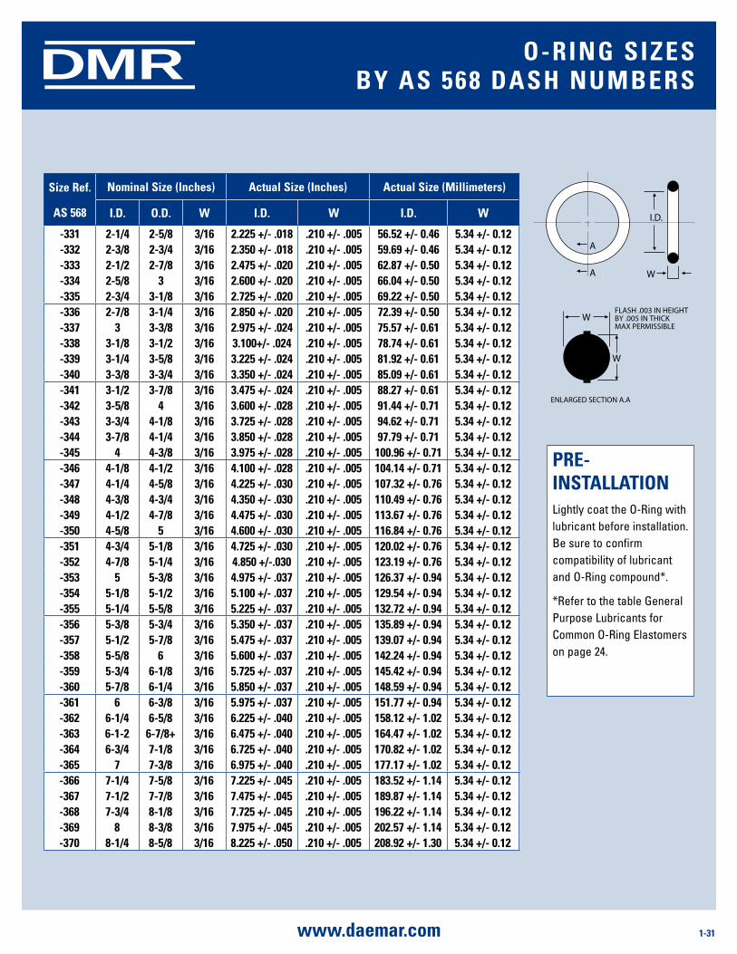
1-31www.daemar.com
DMR
size ref.
as 568
nominal size (inches) actual size (inches) actual size (millimeters)
i.d. o.d. W i.d. W i.d. W
-331 2-1/4 2-5/8 3/16 2.225 +/- .018 .210 +/- .005 56.52 +/- 0.46 5.34 +/- 0.12-332 2-3/8 2-3/4 3/16 2.350 +/- .018 .210 +/- .005 59.69 +/- 0.46 5.34 +/- 0.12-333 2-1/2 2-7/8 3/16 2.475 +/- .020 .210 +/- .005 62.87 +/- 0.50 5.34 +/- 0.12-334 2-5/8 3 3/16 2.600 +/- .020 .210 +/- .005 66.04 +/- 0.50 5.34 +/- 0.12-335 2-3/4 3-1/8 3/16 2.725 +/- .020 .210 +/- .005 69.22 +/- 0.50 5.34 +/- 0.12-336 2-7/8 3-1/4 3/16 2.850 +/- .020 .210 +/- .005 72.39 +/- 0.50 5.34 +/- 0.12-337 3 3-3/8 3/16 2.975 +/- .024 .210 +/- .005 75.57 +/- 0.61 5.34 +/- 0.12-338 3-1/8 3-1/2 3/16 3.100+/- .024 .210 +/- .005 78.74 +/- 0.61 5.34 +/- 0.12-339 3-1/4 3-5/8 3/16 3.225 +/- .024 .210 +/- .005 81.92 +/- 0.61 5.34 +/- 0.12-340 3-3/8 3-3/4 3/16 3.350 +/- .024 .210 +/- .005 85.09 +/- 0.61 5.34 +/- 0.12-341 3-1/2 3-7/8 3/16 3.475 +/- .024 .210 +/- .005 88.27 +/- 0.61 5.34 +/- 0.12-342 3-5/8 4 3/16 3.600 +/- .028 .210 +/- .005 91.44 +/- 0.71 5.34 +/- 0.12-343 3-3/4 4-1/8 3/16 3.725 +/- .028 .210 +/- .005 94.62 +/- 0.71 5.34 +/- 0.12-344 3-7/8 4-1/4 3/16 3.850 +/- .028 .210 +/- .005 97.79 +/- 0.71 5.34 +/- 0.12-345 4 4-3/8 3/16 3.975 +/- .028 .210 +/- .005 100.96 +/- 0.71 5.34 +/- 0.12-346 4-1/8 4-1/2 3/16 4.100 +/- .028 .210 +/- .005 104.14 +/- 0.71 5.34 +/- 0.12-347 4-1/4 4-5/8 3/16 4.225 +/- .030 .210 +/- .005 107.32 +/- 0.76 5.34 +/- 0.12-348 4-3/8 4-3/4 3/16 4.350 +/- .030 .210 +/- .005 110.49 +/- 0.76 5.34 +/- 0.12-349 4-1/2 4-7/8 3/16 4.475 +/- .030 .210 +/- .005 113.67 +/- 0.76 5.34 +/- 0.12-350 4-5/8 5 3/16 4.600 +/- .030 .210 +/- .005 116.84 +/- 0.76 5.34 +/- 0.12-351 4-3/4 5-1/8 3/16 4.725 +/- .030 .210 +/- .005 120.02 +/- 0.76 5.34 +/- 0.12-352 4-7/8 5-1/4 3/16 4.850 +/-.030 .210 +/- .005 123.19 +/- 0.76 5.34 +/- 0.12-353 5 5-3/8 3/16 4.975 +/- .037 .210 +/- .005 126.37 +/- 0.94 5.34 +/- 0.12-354 5-1/8 5-1/2 3/16 5.100 +/- .037 .210 +/- .005 129.54 +/- 0.94 5.34 +/- 0.12-355 5-1/4 5-5/8 3/16 5.225 +/- .037 .210 +/- .005 132.72 +/- 0.94 5.34 +/- 0.12-356 5-3/8 5-3/4 3/16 5.350 +/- .037 .210 +/- .005 135.89 +/- 0.94 5.34 +/- 0.12-357 5-1/2 5-7/8 3/16 5.475 +/- .037 .210 +/- .005 139.07 +/- 0.94 5.34 +/- 0.12-358 5-5/8 6 3/16 5.600 +/- .037 .210 +/- .005 142.24 +/- 0.94 5.34 +/- 0.12-359 5-3/4 6-1/8 3/16 5.725 +/- .037 .210 +/- .005 145.42 +/- 0.94 5.34 +/- 0.12-360 5-7/8 6-1/4 3/16 5.850 +/- .037 .210 +/- .005 148.59 +/- 0.94 5.34 +/- 0.12-361 6 6-3/8 3/16 5.975 +/- .037 .210 +/- .005 151.77 +/- 0.94 5.34 +/- 0.12-362 6-1/4 6-5/8 3/16 6.225 +/- .040 .210 +/- .005 158.12 +/- 1.02 5.34 +/- 0.12-363 6-1-2 6-7/8+ 3/16 6.475 +/- .040 .210 +/- .005 164.47 +/- 1.02 5.34 +/- 0.12-364 6-3/4 7-1/8 3/16 6.725 +/- .040 .210 +/- .005 170.82 +/- 1.02 5.34 +/- 0.12-365 7 7-3/8 3/16 6.975 +/- .040 .210 +/- .005 177.17 +/- 1.02 5.34 +/- 0.12-366 7-1/4 7-5/8 3/16 7.225 +/- .045 .210 +/- .005 183.52 +/- 1.14 5.34 +/- 0.12-367 7-1/2 7-7/8 3/16 7.475 +/- .045 .210 +/- .005 189.87 +/- 1.14 5.34 +/- 0.12-368 7-3/4 8-1/8 3/16 7.725 +/- .045 .210 +/- .005 196.22 +/- 1.14 5.34 +/- 0.12-369 8 8-3/8 3/16 7.975 +/- .045 .210 +/- .005 202.57 +/- 1.14 5.34 +/- 0.12-370 8-1/4 8-5/8 3/16 8.225 +/- .050 .210 +/- .005 208.92 +/- 1.30 5.34 +/- 0.12
PrE- insTallaTionLightly coat the O-Ring with lubricant before installation. Be sure to confirm compatibility of lubricant and O-Ring compound*.
*Refer to the table General Purpose Lubricants for Common O-Ring Elastomers on page 24.
o-ring siZEsBy as 568 dasH numBErs
A
A W
W
W
I.D.
FLASH .003 IN HEIGHTBY .005 IN THICK MAX PERMISSIBLE
ENLARGED SECTION A.A
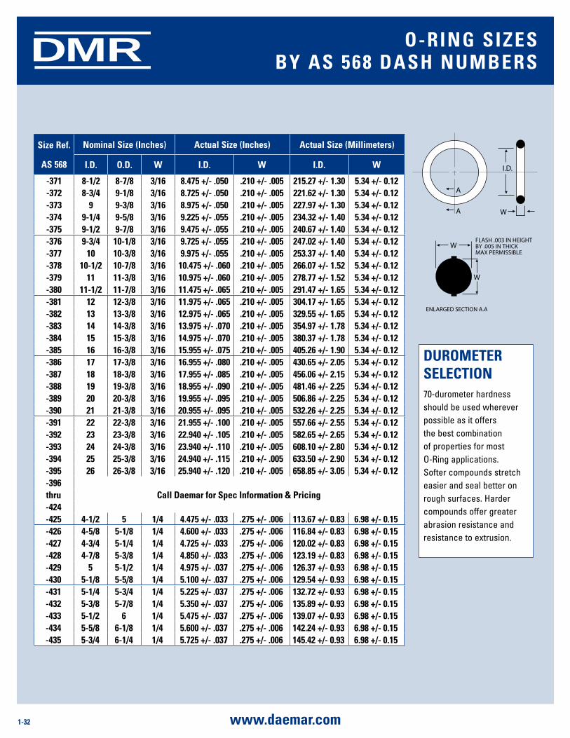
1-32 www.daemar.com
DMR
size ref.
as 568
nominal size (inches) actual size (inches) actual size (millimeters)
i.d. o.d. W i.d. W i.d. W
-371 8-1/2 8-7/8 3/16 8.475 +/- .050 .210 +/- .005 215.27 +/- 1.30 5.34 +/- 0.12-372 8-3/4 9-1/8 3/16 8.725 +/- .050 .210 +/- .005 221.62 +/- 1.30 5.34 +/- 0.12-373 9 9-3/8 3/16 8.975 +/- .050 .210 +/- .005 227.97 +/- 1.30 5.34 +/- 0.12-374 9-1/4 9-5/8 3/16 9.225 +/- .055 .210 +/- .005 234.32 +/- 1.40 5.34 +/- 0.12-375 9-1/2 9-7/8 3/16 9.475 +/- .055 .210 +/- .005 240.67 +/- 1.40 5.34 +/- 0.12-376 9-3/4 10-1/8 3/16 9.725 +/- .055 .210 +/- .005 247.02 +/- 1.40 5.34 +/- 0.12-377 10 10-3/8 3/16 9.975 +/- .055 .210 +/- .005 253.37 +/- 1.40 5.34 +/- 0.12-378 10-1/2 10-7/8 3/16 10.475 +/- .060 .210 +/- .005 266.07 +/- 1.52 5.34 +/- 0.12-379 11 11-3/8 3/16 10.975 +/- .060 .210 +/- .005 278.77 +/- 1.52 5.34 +/- 0.12-380 11-1/2 11-7/8 3/16 11.475 +/- .065 .210 +/- .005 291.47 +/- 1.65 5.34 +/- 0.12-381 12 12-3/8 3/16 11.975 +/- .065 .210 +/- .005 304.17 +/- 1.65 5.34 +/- 0.12-382 13 13-3/8 3/16 12.975 +/- .065 .210 +/- .005 329.55 +/- 1.65 5.34 +/- 0.12-383 14 14-3/8 3/16 13.975 +/- .070 .210 +/- .005 354.97 +/- 1.78 5.34 +/- 0.12-384 15 15-3/8 3/16 14.975 +/- .070 .210 +/- .005 380.37 +/- 1.78 5.34 +/- 0.12-385 16 16-3/8 3/16 15.955 +/- .075 .210 +/- .005 405.26 +/- 1.90 5.34 +/- 0.12-386 17 17-3/8 3/16 16.955 +/- .080 .210 +/- .005 430.65 +/- 2.05 5.34 +/- 0.12-387 18 18-3/8 3/16 17.955 +/- .085 .210 +/- .005 456.06 +/- 2.15 5.34 +/- 0.12-388 19 19-3/8 3/16 18.955 +/- .090 .210 +/- .005 481.46 +/- 2.25 5.34 +/- 0.12-389 20 20-3/8 3/16 19.955 +/- .095 .210 +/- .005 506.86 +/- 2.25 5.34 +/- 0.12-390 21 21-3/8 3/16 20.955 +/- .095 .210 +/- .005 532.26 +/- 2.25 5.34 +/- 0.12-391 22 22-3/8 3/16 21.955 +/- .100 .210 +/- .005 557.66 +/- 2.55 5.34 +/- 0.12-392 23 23-3/8 3/16 22.940 +/- .105 .210 +/- .005 582.65 +/- 2.65 5.34 +/- 0.12-393 24 24-3/8 3/16 23.940 +/- .110 .210 +/- .005 608.10 +/- 2.80 5.34 +/- 0.12-394 25 25-3/8 3/16 24.940 +/- .115 .210 +/- .005 633.50 +/- 2.90 5.34 +/- 0.12-395 26 26-3/8 3/16 25.940 +/- .120 .210 +/- .005 658.85 +/- 3.05 5.34 +/- 0.12-396
Call daemar for spec information & Pricingthru-424-425 4-1/2 5 1/4 4.475 +/- .033 .275 +/- .006 113.67 +/- 0.83 6.98 +/- 0.15-426 4-5/8 5-1/8 1/4 4.600 +/- .033 .275 +/- .006 116.84 +/- 0.83 6.98 +/- 0.15-427 4-3/4 5-1/4 1/4 4.725 +/- .033 .275 +/- .006 120.02 +/- 0.83 6.98 +/- 0.15-428 4-7/8 5-3/8 1/4 4.850 +/- .033 .275 +/- .006 123.19 +/- 0.83 6.98 +/- 0.15-429 5 5-1/2 1/4 4.975 +/- .037 .275 +/- .006 126.37 +/- 0.93 6.98 +/- 0.15-430 5-1/8 5-5/8 1/4 5.100 +/- .037 .275 +/- .006 129.54 +/- 0.93 6.98 +/- 0.15-431 5-1/4 5-3/4 1/4 5.225 +/- .037 .275 +/- .006 132.72 +/- 0.93 6.98 +/- 0.15-432 5-3/8 5-7/8 1/4 5.350 +/- .037 .275 +/- .006 135.89 +/- 0.93 6.98 +/- 0.15-433 5-1/2 6 1/4 5.475 +/- .037 .275 +/- .006 139.07 +/- 0.93 6.98 +/- 0.15-434 5-5/8 6-1/8 1/4 5.600 +/- .037 .275 +/- .006 142.24 +/- 0.93 6.98 +/- 0.15-435 5-3/4 6-1/4 1/4 5.725 +/- .037 .275 +/- .006 145.42 +/- 0.93 6.98 +/- 0.15
duromETEr sElECTion70-durometer hardness should be used wherever possible as it offers the best combination of properties for most O-Ring applications. Softer compounds stretch easier and seal better on rough surfaces. Harder compounds offer greater abrasion resistance and resistance to extrusion.
o-ring siZEsBy as 568 dasH numBErs
A
A W
W
W
I.D.
FLASH .003 IN HEIGHTBY .005 IN THICK MAX PERMISSIBLE
ENLARGED SECTION A.A
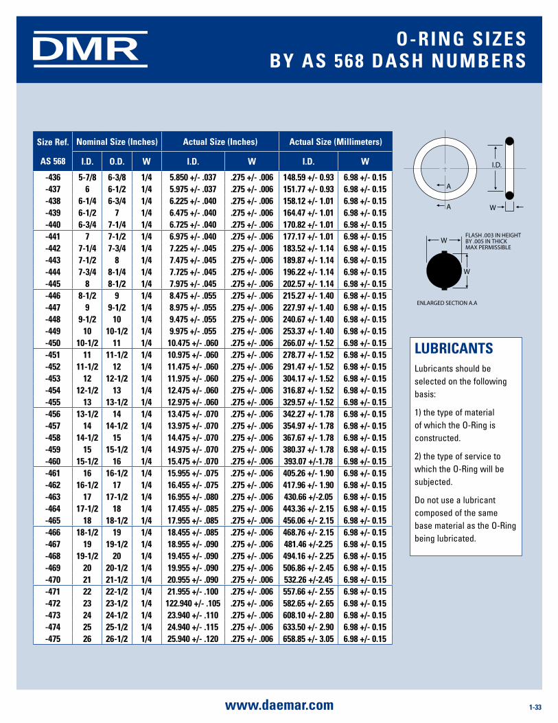
1-33www.daemar.com
DMR
size ref.
as 568
nominal size (inches) actual size (inches) actual size (millimeters)
i.d. o.d. W i.d. W i.d. W
-436 5-7/8 6-3/8 1/4 5.850 +/- .037 .275 +/- .006 148.59 +/- 0.93 6.98 +/- 0.15-437 6 6-1/2 1/4 5.975 +/- .037 .275 +/- .006 151.77 +/- 0.93 6.98 +/- 0.15-438 6-1/4 6-3/4 1/4 6.225 +/- .040 .275 +/- .006 158.12 +/- 1.01 6.98 +/- 0.15-439 6-1/2 7 1/4 6.475 +/- .040 .275 +/- .006 164.47 +/- 1.01 6.98 +/- 0.15-440 6-3/4 7-1/4 1/4 6.725 +/- .040 .275 +/- .006 170.82 +/- 1.01 6.98 +/- 0.15-441 7 7-1/2 1/4 6.975 +/- .040 .275 +/- .006 177.17 +/- 1.01 6.98 +/- 0.15-442 7-1/4 7-3/4 1/4 7.225 +/- .045 .275 +/- .006 183.52 +/- 1.14 6.98 +/- 0.15-443 7-1/2 8 1/4 7.475 +/- .045 .275 +/- .006 189.87 +/- 1.14 6.98 +/- 0.15-444 7-3/4 8-1/4 1/4 7.725 +/- .045 .275 +/- .006 196.22 +/- 1.14 6.98 +/- 0.15-445 8 8-1/2 1/4 7.975 +/- .045 .275 +/- .006 202.57 +/- 1.14 6.98 +/- 0.15-446 8-1/2 9 1/4 8.475 +/- .055 .275 +/- .006 215.27 +/- 1.40 6.98 +/- 0.15-447 9 9-1/2 1/4 8.975 +/- .055 .275 +/- .006 227.97 +/- 1.40 6.98 +/- 0.15-448 9-1/2 10 1/4 9.475 +/- .055 .275 +/- .006 240.67 +/- 1.40 6.98 +/- 0.15-449 10 10-1/2 1/4 9.975 +/- .055 .275 +/- .006 253.37 +/- 1.40 6.98 +/- 0.15-450 10-1/2 11 1/4 10.475 +/- .060 .275 +/- .006 266.07 +/- 1.52 6.98 +/- 0.15-451 11 11-1/2 1/4 10.975 +/- .060 .275 +/- .006 278.77 +/- 1.52 6.98 +/- 0.15-452 11-1/2 12 1/4 11.475 +/- .060 .275 +/- .006 291.47 +/- 1.52 6.98 +/- 0.15-453 12 12-1/2 1/4 11.975 +/- .060 .275 +/- .006 304.17 +/- 1.52 6.98 +/- 0.15-454 12-1/2 13 1/4 12.475 +/- .060 .275 +/- .006 316.87 +/- 1.52 6.98 +/- 0.15-455 13 13-1/2 1/4 12.975 +/- .060 .275 +/- .006 329.57 +/- 1.52 6.98 +/- 0.15-456 13-1/2 14 1/4 13.475 +/- .070 .275 +/- .006 342.27 +/- 1.78 6.98 +/- 0.15-457 14 14-1/2 1/4 13.975 +/- .070 .275 +/- .006 354.97 +/- 1.78 6.98 +/- 0.15-458 14-1/2 15 1/4 14.475 +/- .070 .275 +/- .006 367.67 +/- 1.78 6.98 +/- 0.15-459 15 15-1/2 1/4 14.975 +/- .070 .275 +/- .006 380.37 +/- 1.78 6.98 +/- 0.15-460 15-1/2 16 1/4 15.475 +/- .070 .275 +/- .006 393.07 +/-1.78 6.98 +/- 0.15-461 16 16-1/2 1/4 15.955 +/- .075 .275 +/- .006 405.26 +/- 1.90 6.98 +/- 0.15-462 16-1/2 17 1/4 16.455 +/- .075 .275 +/- .006 417.96 +/- 1.90 6.98 +/- 0.15-463 17 17-1/2 1/4 16.955 +/- .080 .275 +/- .006 430.66 +/-2.05 6.98 +/- 0.15-464 17-1/2 18 1/4 17.455 +/- .085 .275 +/- .006 443.36 +/- 2.15 6.98 +/- 0.15-465 18 18-1/2 1/4 17.955 +/- .085 .275 +/- .006 456.06 +/- 2.15 6.98 +/- 0.15-466 18-1/2 19 1/4 18.455 +/- .085 .275 +/- .006 468.76 +/- 2.15 6.98 +/- 0.15-467 19 19-1/2 1/4 18.955 +/- .090 .275 +/- .006 481.46 +/-2.25 6.98 +/- 0.15-468 19-1/2 20 1/4 19.455 +/- .090 .275 +/- .006 494.16 +/- 2.25 6.98 +/- 0.15-469 20 20-1/2 1/4 19.955 +/- .090 .275 +/- .006 506.86 +/- 2.45 6.98 +/- 0.15-470 21 21-1/2 1/4 20.955 +/- .090 .275 +/- .006 532.26 +/-2.45 6.98 +/- 0.15-471 22 22-1/2 1/4 21.955 +/- .100 .275 +/- .006 557.66 +/- 2.55 6.98 +/- 0.15-472 23 23-1/2 1/4 122.940 +/- .105 .275 +/- .006 582.65 +/- 2.65 6.98 +/- 0.15-473 24 24-1/2 1/4 23.940 +/- .110 .275 +/- .006 608.10 +/- 2.80 6.98 +/- 0.15-474 25 25-1/2 1/4 24.940 +/- .115 .275 +/- .006 633.50 +/- 2.90 6.98 +/- 0.15-475 26 26-1/2 1/4 25.940 +/- .120 .275 +/- .006 658.85 +/- 3.05 6.98 +/- 0.15
luBriCanTsLubricants should be selected on the following basis:
1) the type of material of which the O-Ring is constructed.
2) the type of service to which the O-Ring will be subjected.
Do not use a lubricant composed of the same base material as the O-Ring being lubricated.
o-ring siZEsBy as 568 dasH numBErs
A
A W
W
W
I.D.
FLASH .003 IN HEIGHTBY .005 IN THICK MAX PERMISSIBLE
ENLARGED SECTION A.A
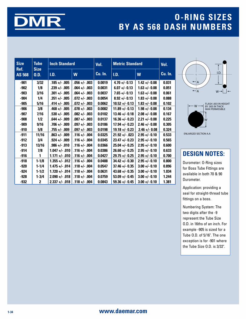
1-34 www.daemar.com
DMR
size ref. as 568
Tube size o.d.
inch standard Vol.
Cu. in.
metric standard Vol.
Cu. in.i.d. W i.d. W
-901 3/32 .185 +/- .005 .056 +/- .003 0.0019 4.70 +/- 0.13 1.42 +/- 0.08 0.031-902 1/8 .239 +/- .005 .064 +/- .003 0.0031 6.07 +/- 0.13 1.63 +/- 0.08 0.051-903 3/16 .301 +/- .005 .064 +/- .003 0.0037 7.65 +/- 0.13 1.63 +/- 0.08 0.061-904 1/4 .351 +/- .005 .072 +/- .003 0.0054 8.92 +/- 0.13 1.83 +/- 0.08 0.088-905 5/16 .414 +/- .005 .072 +/- .003 0.0062 10.52 +/- 0.13 1.83 +/- 0.08 0.102-906 3/8 .468 +/- .005 .078 +/- .003 0.0082 11.89 +/- 0.13 1.98 +/- 0.08 0.134-907 7/16 .530 +/- .005 .082 +/- .003 0.0102 13.46 +/- 0.18 2.08 +/- 0.08 0.167-908 1/2 .644 +/- .009 .087 +/- .003 0.0137 16.36 +/- 0.23 2.21 +/- 0.08 0.225-909 9/16 .706 +/- .009 .097 +/- .003 0.0186 17.94 +/- 0.23 2.46 +/- 0.08 0.305-910 5/8 .755 +/- .009 .097 +/- .003 0.0198 19.18 +/- 0.23 2.46 +/- 0.08 0.324-911 11/16 .863 +/- .009 .116 +/- .004 0.0325 21.92 +/- .023 2.95 +/- 0.10 0.533-912 3/4 .924 +/- .009 .116 +/- .004 0.0345 23.47 +/- 0.23 2.95 +/- 0.10 0.565-913 13/16 .986 +/- .010 .116 +/- .004 0.0366 25.04 +/- 0.25 2.95 +/- 0.10 0.600-914 7/8 1.047 +/- .010 .116 +/- .004 0.0386 26.60 +/- 0.25 2.95 +/- 0.10 0.633-916 1 1.171 +/- .010 .116 +/- .004 0.0427 29.75 +/- 0.25 2.95 +/- 0.10 0.700-918 1-1/8 1.355 +/- .012 .116 +/- .004 0.0488 34.42 +/- 0.30 2.95 +/- 0.10 0.800-920 1-1/4 1.475 +/- .014 .118 +/- .004 0.0547 37.46 +/- 0.35 3.00 +/- 0.10 0.896-924 1-1/2 1.720 +/- .014 .118 +/- .004 0.0631 43.68 +/- 0.35 3.00 +/- 0.10 1.034-928 1-3/4 2.090 +/- .018 .118 +/- .004 0.0759 53.09 +/- 0.45 3.00 +/- 0.10 1.244-932 2 2.337 +/- .018 .118 +/- .004 0.0843 59.36 +/- 0.45 3.00 +/- 0.10 1.381
dEsign noTEs:Durometer: O-Ring sizes for Boss Tube Fittings are available in both 70 & 90 Durometer.
Application: providing a seal for straight-thread tube fittings on a boss.
Numbering System: The two digits after the -9 represent the Tube Size O.D. in 16ths of an inch. For example -905 is sized for a Tube O.D. of 5/16". The one exception is for -901 where the Tube Size O.D. is 3/32".
o-ring siZEsBy as 568 dasH numBErs
A
A W
W
W
I.D.
FLASH .003 IN HEIGHTBY .005 IN THICK MAX PERMISSIBLE
ENLARGED SECTION A.A
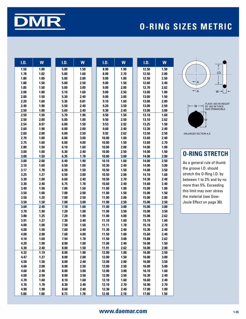
1-35www.daemar.com
DMR
i.d. W i.d. W i.d. W i.d. W1.50 1.00 5.00 1.50 8.90 1.90 12.50 1.50 1.78 1.02 5.00 1.60 8.90 2.70 12.50 2.00 1.80 1.00 5.00 2.00 9.00 1.00 12.50 2.50 1.80 1.50 5.00 2.50 9.00 1.50 12.60 2.40 1.85 1.50 5.00 3.00 9.00 2.00 12.70 2.62 2.00 1.00 5.10 1.60 9.00 2.50 13.00 1.00 2.00 1.50 5.30 2.40 9.00 3.00 13.00 1.50 2.20 1.60 5.36 0.81 9.10 1.60 13.00 2.00 2.40 1.90 5.50 2.40 9.20 3.50 13.00 2.50 2.50 1.00 5.60 2.40 9.30 2.40 13.00 3.00 2.50 1.50 5.70 1.90 9.50 1.50 13.10 1.60 2.50 2.00 6.00 1.00 9.50 2.50 13.10 2.62 2.54 0.97 6.00 1.50 9.53 2.92 13.25 1.50 2.60 1.90 6.00 2.00 9.60 2.40 13.30 2.40 2.60 2.00 6.00 2.50 9.92 2.62 13.50 2.50 2.70 1.00 6.00 3.00 10.00 1.00 13.60 2.40 2.75 1.60 6.00 4.00 10.00 1.50 13.60 2.70 2.80 1.50 6.10 1.60 10.00 2.00 14.00 1.00 3.00 1.00 6.30 2.40 10.00 2.50 14.00 1.50 3.00 1.50 6.35 1.78 10.00 3.00 14.00 2.00 3.00 2.00 6.40 1.90 10.10 1.60 14.00 2.50 3.10 1.60 6.50 1.00 10.30 2.40 14.00 3.00 3.17 1.78 6.50 1.50 10.50 1.50 14.00 3.50 3.25 1.27 6.50 3.00 10.50 2.00 14.10 1.60 3.30 1.00 6.60 2.40 10.50 2.70 14.30 2.40 3.30 2.40 6.75 1.78 10.60 2.40 14.60 2.40 3.40 1.90 7.00 1.50 11.00 1.00 15.00 1.00 3.50 1.00 7.00 2.00 11.00 1.50 15.00 1.50 3.50 1.20 7.00 2.50 11.00 2.00 15.00 2.00 3.50 1.50 7.00 3.00 11.00 2.50 15.00 2.50 3.60 2.40 7.10 1.60 11.00 3.00 15.00 3.00 3.70 1.90 7.20 1.00 11.00 3.50 15.00 3.50 3.80 1.25 7.20 1.90 11.00 4.00 15.08 2.62 3.91 1.27 7.30 2.40 11.10 1.60 15.10 1.60 4.00 1.00 7.50 1.50 11.11 1.78 15.10 2.70 4.00 1.50 7.60 2.40 11.30 2.40 15.30 2.40 4.00 2.00 7.60 4.00 11.50 1.00 15.60 2.40 4.10 1.60 7.94 1.78 11.50 3.00 15.88 2.62 4.20 1.90 8.00 1.00 11.60 2.40 16.00 1.50 4.30 2.40 8.00 1.50 11.91 2.62 16.00 2.00 4.32 1.19 8.00 1.90 12.00 1.00 16.00 2.50 4.47 1.27 8.00 2.00 12.00 1.50 16.00 3.00 4.50 1.50 8.00 2.40 12.00 2.00 16.00 3.50 4.60 2.00 8.00 2.50 12.00 2.50 16.00 5.00 4.60 2.40 8.00 3.00 12.00 3.00 16.10 1.60 4.60 2.50 8.00 3.50 12.00 3.50 16.30 2.40 4.70 1.60 8.10 1.60 12.10 1.60 16.60 2.40 4.76 1.78 8.30 2.40 12.10 2.70 16.90 2.70 4.90 1.90 8.60 2.40 12.30 2.40 17.00 1.00 5.00 1.00 8.73 1.78 12.40 2.18 17.00 1.50
o-ring sTrETCHAs a general rule of thumb the groove I.D. should stretch the O-Ring I.D. by between 1 to 3% and by no more than 5%. Exceeding this limit may over stress the material (see Gow-Joule Effect on page 36).
o-ring siZEs mETriC
A
A W
W
W
I.D.
FLASH .003 IN HEIGHTBY .005 IN THICK MAX PERMISSIBLE
ENLARGED SECTION A.A
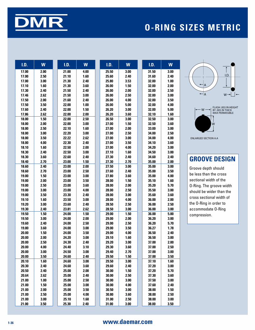
1-36 www.daemar.com
DMR
i.d. W i.d. W i.d. W i.d. W17.00 2.00 21.00 4.00 25.50 3.00 31.50 3.00 17.00 2.50 21.10 1.60 25.60 2.40 31.60 2.40 17.00 3.00 21.30 2.40 25.80 3.53 32.00 1.00 17.10 1.60 21.30 3.60 26.00 1.50 32.00 2.00 17.30 2.40 21.50 2.40 26.00 2.00 32.00 2.50 17.46 2.62 21.50 3.00 26.00 2.50 32.00 3.00 17.50 2.00 21.60 2.40 26.00 4.00 32.00 3.50 17.50 3.50 22.00 1.00 26.00 5.00 32.00 4.00 17.60 2.40 22.00 1.50 26.20 3.00 32.00 5.00 17.86 2.62 22.00 2.00 26.20 3.60 32.10 1.60 18.00 1.50 22.00 2.50 26.50 3.00 32.50 3.00 18.00 2.00 22.00 3.00 27.00 1.50 32.50 3.60 18.00 2.50 22.10 1.60 27.00 2.00 33.00 3.00 18.00 3.00 22.20 3.00 27.00 2.50 34.00 2.50 18.00 3.50 22.22 2.62 27.00 3.00 34.00 4.00 18.00 4.00 22.30 2.40 27.00 3.50 34.10 3.60 18.10 1.60 22.50 2.00 27.00 4.00 34.20 3.00 18.30 2.40 22.50 3.00 27.10 1.60 34.50 3.00 18.30 3.60 22.60 2.40 27.30 2.40 34.60 2.40 18.40 2.70 23.00 1.50 27.30 2.70 35.00 2.00 18.60 2.40 23.00 2.00 27.50 3.00 35.00 3.00 18.60 2.70 23.00 2.50 27.60 2.40 35.00 3.50 19.00 1.50 23.00 3.00 27.80 3.60 35.00 4.00 19.00 2.00 23.00 3.50 28.00 1.50 35.10 1.60 19.00 2.50 23.00 3.60 28.00 2.00 35.20 5.70 19.00 3.00 23.00 4.00 28.00 2.50 35.50 3.00 19.00 3.50 23.30 2.40 28.00 3.00 35.60 3.60 19.10 1.60 23.50 3.00 28.00 4.00 36.00 2.00 19.20 3.00 23.60 2.40 28.50 2.50 36.00 2.50 19.30 2.40 23.81 2.62 28.50 3.00 36.00 3.0019.50 1.50 24.00 1.50 29.00 1.50 36.00 5.00 19.50 3.00 24.00 2.00 29.00 2.00 36.20 3.00 19.60 2.40 24.00 2.50 29.00 2.50 36.20 5.70 19.80 3.60 24.00 3.00 29.00 3.50 36.27 1.78 20.00 1.50 24.00 3.50 29.00 4.00 36.50 2.40 20.00 2.00 24.20 3.00 29.10 1.60 36.50 3.00 20.00 2.50 24.30 2.40 29.20 3.00 37.00 2.00 20.00 4.00 24.40 3.10 29.30 3.60 37.00 2.50 20.00 3.00 24.50 3.00 29.40 2.70 37.00 3.00 20.00 3.50 24.60 2.40 29.50 1.50 37.00 3.50 20.10 1.60 24.60 3.00 29.50 3.00 37.10 1.60 20.30 2.40 24.60 3.60 29.60 2.40 37.20 3.00 20.50 2.40 25.00 2.00 30.00 1.50 37.20 5.70 20.64 2.62 25.00 2.40 30.00 2.50 37.30 3.60 21.00 1.00 25.00 2.50 30.00 3.00 37.50 3.00 21.00 1.50 25.00 3.00 30.00 4.00 37.60 2.40 21.00 2.00 25.00 3.50 30.50 3.00 38.00 1.50 21.00 2.50 25.00 4.00 30.80 3.60 38.00 2.50 21.00 3.00 25.10 1.60 31.00 2.50 38.00 3.00 21.00 3.50 25.30 2.40 31.00 3.00 38.00 3.50
grooVE dEsignGroove depth should be less than the cross sectional width of the O-Ring. The groove width should be wider than the cross sectional width of the O-Ring in order to accommodate O-Ring compression.
o-ring siZEs mETriC
A
A W
W
W
I.D.
FLASH .003 IN HEIGHTBY .005 IN THICK MAX PERMISSIBLE
ENLARGED SECTION A.A
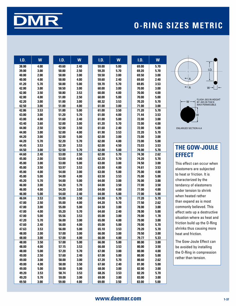
1-37www.daemar.com
DMR
i.d. W i.d. W i.d. W i.d. W38.00 4.00 49.60 2.40 59.00 5.00 69.00 5.70 39.00 3.00 50.00 2.50 59.20 5.70 69.20 5.70 40.00 2.00 50.00 3.00 59.50 3.00 69.50 3.00 40.00 4.00 50.00 4.00 59.60 2.40 69.60 2.40 41.20 5.70 50.00 5.00 59.70 5.70 69.85 3.53 42.00 3.00 50.50 3.00 60.00 3.00 70.00 3.00 42.00 3.50 50.80 3.53 60.00 4.00 70.00 4.00 42.00 4.00 51.00 2.50 60.00 5.00 70.00 5.00 42.20 3.00 51.00 3.00 60.32 3.53 70.20 5.70 42.50 3.00 51.00 4.00 61.00 3.00 71.00 3.0042.86 3.53 51.00 5.00 61.00 3.50 71.20 5.70 43.00 3.00 51.20 5.70 61.00 4.00 71.44 3.53 43.00 4.00 51.60 2.40 61.00 5.00 72.00 3.00 43.40 3.60 52.00 3.00 61.20 5.70 72.00 4.00 44.00 2.50 52.00 3.50 61.60 2.40 72.00 5.00 44.00 3.00 52.00 4.00 61.90 3.53 72.20 5.70 44.20 3.00 52.00 5.00 62.00 3.00 73.00 3.00 44.20 5.70 52.20 5.70 62.00 4.00 73.00 5.00 44.45 3.53 52.39 3.53 62.00 4.50 73.03 3.53 44.50 3.00 52.50 5.70 62.00 5.00 74.00 5.70 44.60 2.40 53.00 2.50 62.00 5.70 74.30 2.62 45.00 2.00 53.00 4.00 62.20 5.70 74.20 5.70 45.00 3.00 53.00 5.00 63.00 3.00 74.50 3.00 45.00 3.50 53.97 3.53 63.00 4.00 74.61 3.53 45.00 4.00 54.00 3.00 63.00 5.00 75.00 4.00 45.00 5.00 54.00 4.00 63.50 3.53 75.00 5.00 45.20 5.70 54.00 5.00 64.00 3.00 76.00 3.00 46.00 3.00 54.20 5.70 64.00 3.50 77.00 3.50 46.00 4.00 54.20 3.00 64.00 4.00 77.00 4.00 46.00 5.00 54.60 2.40 64.00 5.00 77.00 5.00 46.04 3.53 55.00 3.50 64.00 5.70 77.20 5.70 47.00 2.50 55.00 4.00 64.20 5.70 77.50 2.62 47.00 3.00 55.00 5.00 64.50 3.00 78.00 3.00 47.00 4.00 55.20 5.70 64.60 2.40 78.00 5.00 47.00 5.00 55.56 3.53 65.00 3.00 79.00 1.78 47.20 5.70 56.00 3.00 65.00 4.00 79.00 3.00 47.60 2.40 56.00 4.00 65.00 5.00 79.00 5.70 47.63 3.53 56.00 5.00 65.10 3.53 79.20 5.70 48.00 2.00 57.00 3.00 66.00 3.00 79.50 3.00 48.00 3.00 57.00 4.00 66.00 4.00 79.77 5.33 48.00 3.50 57.00 5.00 66.00 5.00 80.00 3.00 48.00 4.00 57.15 3.53 66.68 3.53 80.00 3.50 48.00 5.00 57.20 5.70 67.00 3.00 80.00 4.00 49.00 2.50 57.60 2.40 67.00 5.00 80.00 5.00 49.00 3.00 58.00 3.00 67.20 5.70 80.60 2.62 49.00 4.00 58.00 3.50 67.60 2.40 81.00 5.00 49.00 5.00 58.00 5.00 68.00 3.00 82.00 3.00 49.20 3.53 58.74 3.53 68.26 3.53 82.20 5.70 49.20 5.70 59.00 3.00 69.00 3.00 83.00 3.00 49.50 3.00 59.00 4.00 69.00 3.50 83.00 5.00
THE goW-JoulE EFFECTThis effect can occur when elastomers are subjected to heat or friction. It is characterized by the tendancy of elastomers under tension to shrink when heated rather than expand as is most commonly believed. This effect sets up a destructive situation where as heat and friction build up the O-Ring shrinks thus causing more heat and friction.
The Gow-Joule Effect can be avoided by installing the O-Ring in compression rather than tension.
o-ring siZEs mETriC
A
A W
W
W
I.D.
FLASH .003 IN HEIGHTBY .005 IN THICK MAX PERMISSIBLE
ENLARGED SECTION A.A
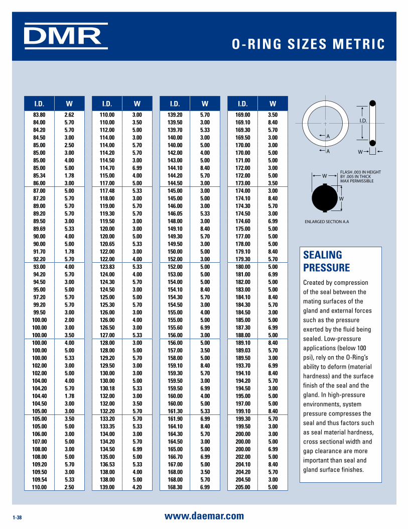
1-38 www.daemar.com
DMR
i.d. W i.d. W i.d. W i.d. W83.80 2.62 110.00 3.00 139.20 5.70 169.00 3.50 84.00 5.70 110.00 3.50 139.50 3.00 169.10 8.40 84.20 5.70 112.00 5.00 139.70 5.33 169.30 5.70 84.50 3.00 114.00 3.00 140.00 3.00 169.50 3.00 85.00 2.50 114.00 5.70 140.00 5.00 170.00 3.00 85.00 3.00 114.20 5.70 142.00 4.00 170.00 5.00 85.00 4.00 114.50 3.00 143.00 5.00 171.00 5.00 85.00 5.00 114.70 6.99 144.10 8.40 172.00 3.00 85.34 1.78 115.00 4.00 144.20 5.70 172.00 5.00 86.00 3.00 117.00 5.00 144.50 3.00 173.00 3.50 87.00 5.00 117.48 5.33 145.00 3.00 174.00 3.00 87.20 5.70 118.00 3.00 145.00 5.00 174.10 8.40 89.00 5.70 119.00 5.70 146.00 3.00 174.30 5.70 89.20 5.70 119.30 5.70 146.05 5.33 174.50 3.00 89.50 3.00 119.50 3.00 148.00 3.00 174.60 6.99 89.69 5.33 120.00 3.00 149.10 8.40 175.00 5.00 90.00 4.00 120.00 5.00 149.30 5.70 177.00 5.00 90.00 5.00 120.65 5.33 149.50 3.00 178.00 5.00 91.70 1.78 122.00 3.00 150.00 5.00 179.10 8.40 92.20 5.70 122.00 4.00 152.00 3.00 179.30 5.70 93.00 4.00 123.83 5.33 152.00 5.00 180.00 5.00 94.20 5.70 124.00 4.00 153.00 5.00 181.00 6.99 94.50 3.00 124.30 5.70 154.00 5.00 182.00 5.00 95.00 5.00 124.50 3.00 154.10 8.40 183.00 5.00 97.20 5.70 125.00 5.00 154.30 5.70 184.10 8.40 99.20 5.70 125.30 5.70 154.50 3.00 184.30 5.70 99.50 3.00 126.00 3.00 155.00 4.00 184.50 3.00 100.00 2.00 126.00 4.00 155.00 5.00 185.00 5.00 100.00 3.00 126.50 3.00 155.60 6.99 187.30 6.99 100.00 3.50 127.00 5.33 156.00 3.00 188.00 5.00 100.00 4.00 128.00 3.00 156.00 5.00 189.10 8.40 100.00 5.00 128.00 5.00 157.00 3.50 189.03 5.70 100.00 5.33 129.20 5.70 158.00 5.00 189.50 3.00 102.00 3.00 129.50 3.00 159.10 8.40 193.70 6.99 102.00 5.00 130.00 3.00 159.30 5.70 194.10 8.40 104.00 4.00 130.00 5.00 159.50 3.00 194.20 5.70 104.20 5.70 130.18 5.33 159.50 6.99 194.50 3.00 104.40 1.78 132.00 3.00 160.00 4.00 195.00 5.00 104.50 3.00 132.00 3.50 160.00 5.00 197.00 5.00 105.00 3.00 132.20 5.70 161.30 5.33 199.10 8.40 105.00 3.50 133.20 5.70 161.90 6.99 199.30 5.70 105.00 5.00 133.35 5.33 164.10 8.40 199.50 3.00 106.00 3.00 134.00 3.00 164.30 5.70 200.00 3.00 107.00 5.00 134.20 5.70 164.50 3.00 200.00 5.00 108.00 3.00 134.50 6.99 165.00 5.00 200.00 6.99 108.00 5.00 135.00 5.00 166.70 6.99 202.00 5.00 109.20 5.70 136.53 5.33 167.00 5.00 204.10 8.40 109.50 3.00 138.00 4.00 168.00 3.50 204.20 5.70 109.54 5.33 138.00 5.00 168.00 5.70 204.50 3.00 110.00 2.50 139.00 4.20 168.30 6.99 205.00 5.00
sEaling PrEssurECreated by compression of the seal between the mating surfaces of the gland and external forces such as the pressure exerted by the fluid being sealed. Low-pressure applications (below 100 psi), rely on the O-Ring’s ability to deform (material hardness) and the surface finish of the seal and the gland. In high-pressure environments, system pressure compresses the seal and thus factors such as seal material hardness, cross sectional width and gap clearance are more important than seal and gland surface finishes.
o-ring siZEs mETriC
A
A W
W
W
I.D.
FLASH .003 IN HEIGHTBY .005 IN THICK MAX PERMISSIBLE
ENLARGED SECTION A.A
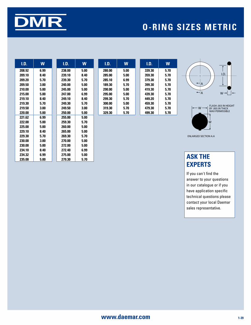
1-39www.daemar.com
DMR
i.d. W i.d. W i.d. W i.d. W208.92 6.99 238.00 5.00 280.00 5.00 339.30 5.70 209.10 8.40 239.10 8.40 285.00 5.00 359.30 5.70 209.20 5.70 239.30 5.70 285.10 6.99 379.30 5.70 209.50 3.00 240.00 5.00 189.30 5.70 399.30 5.70 210.00 5.00 245.00 5.00 290.00 5.00 419.30 5.70 215.00 5.00 247.00 6.99 295.00 5.00 439.30 5.70 219.10 8.40 249.10 8.40 299.30 5.70 449.20 5.70 219.30 5.70 249.30 5.70 300.00 5.00 459.30 5.70 219.50 3.00 249.50 3.00 319.30 5.70 479.30 5.70 220.00 5.00 250.00 5.00 329.30 5.70 499.30 5.70221.62 6.99 255.00 5.00 222.00 5.00 259.30 5.70 225.00 5.00 260.00 5.00 229.10 8.40 265.00 5.00 229.30 5.70 269.30 5.70 230.00 3.00 270.00 5.00 230.00 5.00 272.00 5.00 234.10 8.40 272.40 6.99 234.32 6.99 275.00 5.00 235.00 5.00 279.30 5.70 asK THE
EXPErTsIf you can't find the answer to your questions in our catalogue or if you have application specific technical questions please contact your local Daemar sales representative.
o-ring siZEs mETriC
A
A W
W
W
I.D.
FLASH .003 IN HEIGHTBY .005 IN THICK MAX PERMISSIBLE
ENLARGED SECTION A.A
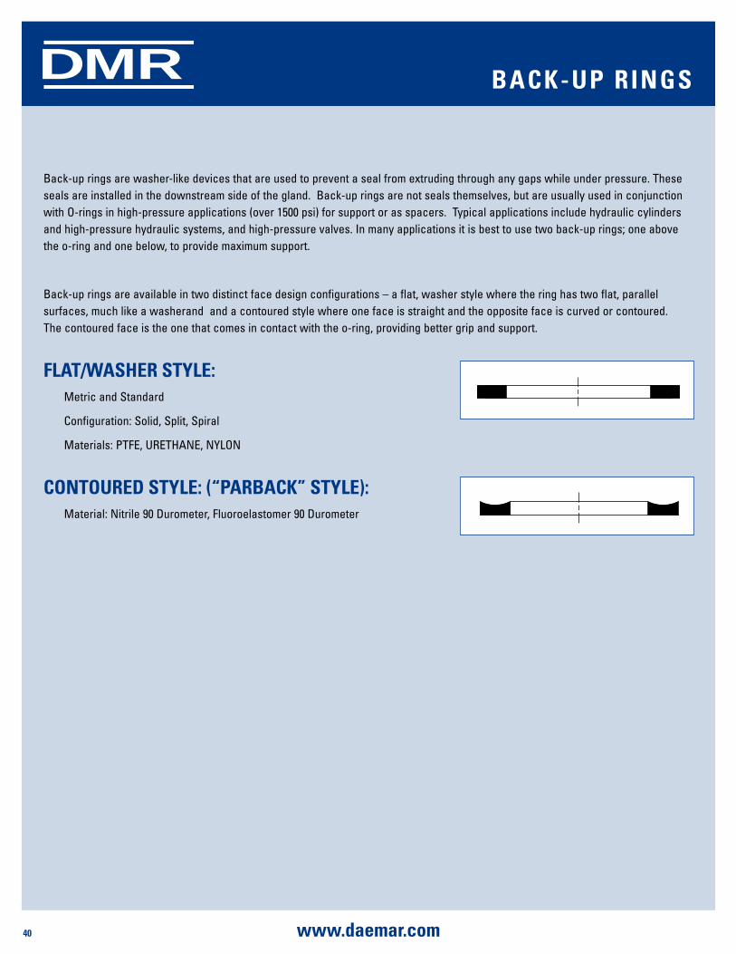
40 www.daemar.com
DMR
Back-up rings are washer-like devices that are used to prevent a seal from extruding through any gaps while under pressure. These seals are installed in the downstream side of the gland. Back-up rings are not seals themselves, but are usually used in conjunction with O-rings in high-pressure applications (over 1500 psi) for support or as spacers. Typical applications include hydraulic cylinders and high-pressure hydraulic systems, and high-pressure valves. In many applications it is best to use two back-up rings; one above the o-ring and one below, to provide maximum support.
Back-up rings are available in two distinct face design configurations – a flat, washer style where the ring has two flat, parallel surfaces, much like a washerand and a contoured style where one face is straight and the opposite face is curved or contoured. The contoured face is the one that comes in contact with the o-ring, providing better grip and support.
FlaT/WasHEr sTylE: Metric and Standard
Configuration: Solid, Split, Spiral
Materials: PTFE, URETHANE, NYLON
ConTourEd sTylE: (“ParBaCK” sTylE): Material: Nitrile 90 Durometer, Fluoroelastomer 90 Durometer
BaCK-uP rings
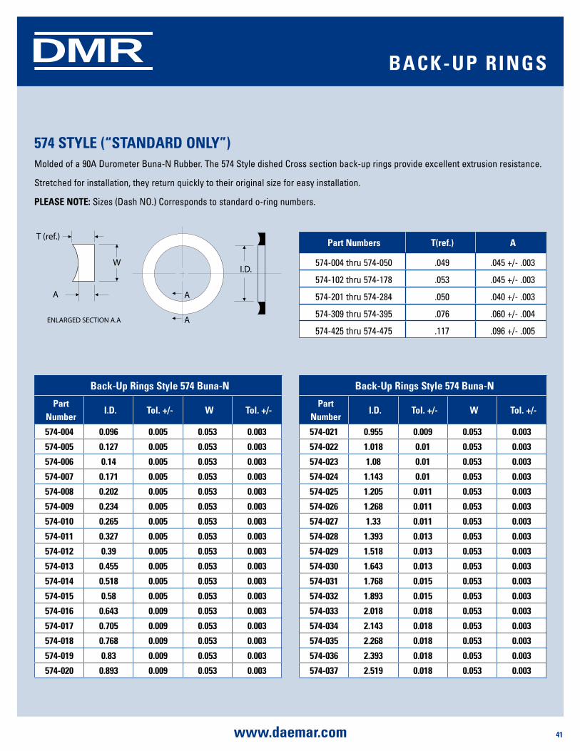
SHAFT SEALS
41www.daemar.com
DMRDMR BaCK-uP rings
574 sTylE (“sTandard only”)Molded of a 90A Durometer Buna-N Rubber. The 574 Style dished Cross section back-up rings provide excellent extrusion resistance.
Stretched for installation, they return quickly to their original size for easy installation.
PlEasE noTE: Sizes (Dash NO.) Corresponds to standard o-ring numbers.
A
A
T (ref.)
WI.D.
ENLARGED SECTION A.A
A
Back-up rings style 574 Buna-n
Part number
i.d. Tol. +/- W Tol. +/-
574-004 0.096 0.005 0.053 0.003
574-005 0.127 0.005 0.053 0.003
574-006 0.14 0.005 0.053 0.003
574-007 0.171 0.005 0.053 0.003
574-008 0.202 0.005 0.053 0.003
574-009 0.234 0.005 0.053 0.003
574-010 0.265 0.005 0.053 0.003
574-011 0.327 0.005 0.053 0.003
574-012 0.39 0.005 0.053 0.003
574-013 0.455 0.005 0.053 0.003
574-014 0.518 0.005 0.053 0.003
574-015 0.58 0.005 0.053 0.003
574-016 0.643 0.009 0.053 0.003
574-017 0.705 0.009 0.053 0.003
574-018 0.768 0.009 0.053 0.003
574-019 0.83 0.009 0.053 0.003
574-020 0.893 0.009 0.053 0.003
Back-up rings style 574 Buna-n
Part number
i.d. Tol. +/- W Tol. +/-
574-021 0.955 0.009 0.053 0.003
574-022 1.018 0.01 0.053 0.003
574-023 1.08 0.01 0.053 0.003
574-024 1.143 0.01 0.053 0.003
574-025 1.205 0.011 0.053 0.003
574-026 1.268 0.011 0.053 0.003
574-027 1.33 0.011 0.053 0.003
574-028 1.393 0.013 0.053 0.003
574-029 1.518 0.013 0.053 0.003
574-030 1.643 0.013 0.053 0.003
574-031 1.768 0.015 0.053 0.003
574-032 1.893 0.015 0.053 0.003
574-033 2.018 0.018 0.053 0.003
574-034 2.143 0.018 0.053 0.003
574-035 2.268 0.018 0.053 0.003
574-036 2.393 0.018 0.053 0.003
574-037 2.519 0.018 0.053 0.003
Part numbers T(ref.) a
574-004 thru 574-050 .049 .045 +/- .003
574-102 thru 574-178 .053 .045 +/- .003
574-201 thru 574-284 .050 .040 +/- .003
574-309 thru 574-395 .076 .060 +/- .004
574-425 thru 574-475 .117 .096 +/- .005
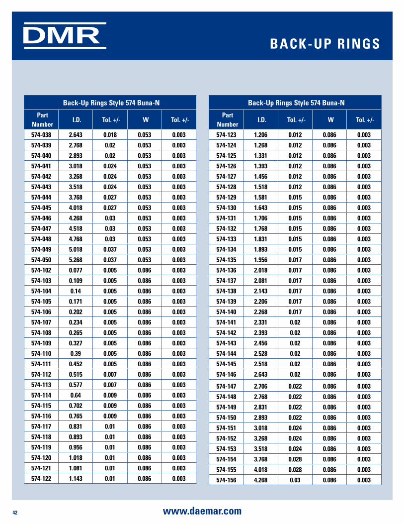
42 www.daemar.com
SHAFT SEALSDMRDMR BaCK-uP rings
Back-up rings style 574 Buna-n
Part number
i.d. Tol. +/- W Tol. +/-
574-038 2.643 0.018 0.053 0.003
574-039 2.768 0.02 0.053 0.003
574-040 2.893 0.02 0.053 0.003
574-041 3.018 0.024 0.053 0.003
574-042 3.268 0.024 0.053 0.003
574-043 3.518 0.024 0.053 0.003
574-044 3.768 0.027 0.053 0.003
574-045 4.018 0.027 0.053 0.003
574-046 4.268 0.03 0.053 0.003
574-047 4.518 0.03 0.053 0.003
574-048 4.768 0.03 0.053 0.003
574-049 5.018 0.037 0.053 0.003
574-050 5.268 0.037 0.053 0.003
574-102 0.077 0.005 0.086 0.003
574-103 0.109 0.005 0.086 0.003
574-104 0.14 0.005 0.086 0.003
574-105 0.171 0.005 0.086 0.003
574-106 0.202 0.005 0.086 0.003
574-107 0.234 0.005 0.086 0.003
574-108 0.265 0.005 0.086 0.003
574-109 0.327 0.005 0.086 0.003
574-110 0.39 0.005 0.086 0.003
574-111 0.452 0.005 0.086 0.003
574-112 0.515 0.007 0.086 0.003
574-113 0.577 0.007 0.086 0.003
574-114 0.64 0.009 0.086 0.003
574-115 0.702 0.009 0.086 0.003
574-116 0.765 0.009 0.086 0.003
574-117 0.831 0.01 0.086 0.003
574-118 0.893 0.01 0.086 0.003
574-119 0.956 0.01 0.086 0.003
574-120 1.018 0.01 0.086 0.003
574-121 1.081 0.01 0.086 0.003
574-122 1.143 0.01 0.086 0.003
Back-up rings style 574 Buna-n
Part number
i.d. Tol. +/- W Tol. +/-
574-123 1.206 0.012 0.086 0.003
574-124 1.268 0.012 0.086 0.003
574-125 1.331 0.012 0.086 0.003
574-126 1.393 0.012 0.086 0.003
574-127 1.456 0.012 0.086 0.003
574-128 1.518 0.012 0.086 0.003
574-129 1.581 0.015 0.086 0.003
574-130 1.643 0.015 0.086 0.003
574-131 1.706 0.015 0.086 0.003
574-132 1.768 0.015 0.086 0.003
574-133 1.831 0.015 0.086 0.003
574-134 1.893 0.015 0.086 0.003
574-135 1.956 0.017 0.086 0.003
574-136 2.018 0.017 0.086 0.003
574-137 2.081 0.017 0.086 0.003
574-138 2.143 0.017 0.086 0.003
574-139 2.206 0.017 0.086 0.003
574-140 2.268 0.017 0.086 0.003
574-141 2.331 0.02 0.086 0.003
574-142 2.393 0.02 0.086 0.003
574-143 2.456 0.02 0.086 0.003
574-144 2.528 0.02 0.086 0.003
574-145 2.518 0.02 0.086 0.003
574-146 2.643 0.02 0.086 0.003
574-147 2.706 0.022 0.086 0.003
574-148 2.768 0.022 0.086 0.003
574-149 2.831 0.022 0.086 0.003
574-150 2.893 0.022 0.086 0.003
574-151 3.018 0.024 0.086 0.003
574-152 3.268 0.024 0.086 0.003
574-153 3.518 0.024 0.086 0.003
574-154 3.768 0.028 0.086 0.003
574-155 4.018 0.028 0.086 0.003
574-156 4.268 0.03 0.086 0.003
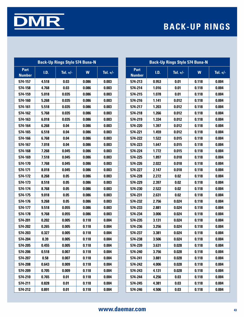
SHAFT SEALS
43www.daemar.com
DMRDMR BaCK-uP rings
Back-up rings style 574 Buna-n
Part number
i.d. Tol. +/- W Tol. +/-
574-157 4.518 0.03 0.086 0.003
574-158 4.768 0.03 0.086 0.003
574-159 5.018 0.035 0.086 0.003
574-160 5.268 0.035 0.086 0.003
574-161 5.518 0.035 0.086 0.003
574-162 5.768 0.035 0.086 0.003
574-163 6.018 0.035 0.086 0.003
574-164 6.268 0.04 0.086 0.003
574-165 6.518 0.04 0.086 0.003
574-166 6.768 0.04 0.086 0.003
574-167 7.018 0.04 0.086 0.003
574-168 7.268 0.045 0.086 0.003
574-169 7.518 0.045 0.086 0.003
574-170 7.768 0.045 0.086 0.003
574-171 8.018 0.045 0.086 0.003
574-172 8.268 0.05 0.086 0.003
574-173 8.518 0.05 0.086 0.003
574-174 8.768 0.05 0.086 0.003
574-175 9.018 0.05 0.086 0.003
574-176 9.268 0.05 0.086 0.003
574-177 9.518 0.055 0.086 0.003
574-178 9.768 0.055 0.086 0.003
574-201 0.202 0.005 0.118 0.004
574-202 0.265 0.005 0.118 0.004
574-203 0.327 0.005 0.118 0.004
574-204 0.39 0.005 0.118 0.004
574-205 0.455 0.005 0.118 0.004
574-206 0.518 0.007 0.118 0.004
574-207 0.58 0.007 0.118 0.004
574-208 0.643 0.009 0.118 0.004
574-209 0.705 0.009 0.118 0.004
574-210 0.765 0.01 0.118 0.004
574-211 0.828 0.01 0.118 0.004
574-212 0.891 0.01 0.118 0.004
Back-up rings style 574 Buna-n
Part number
i.d. Tol. +/- W Tol. +/-
574-213 0.953 0.01 0.118 0.004
574-214 1.016 0.01 0.118 0.004
574-215 1.078 0.01 0.118 0.004
574-216 1.141 0.012 0.118 0.004
574-217 1.203 0.012 0.118 0.004
574-218 1.266 0.012 0.118 0.004
574-219 1.334 0.012 0.118 0.004
574-220 1.397 0.012 0.118 0.004
574-221 1.459 0.012 0.118 0.004
574-222 1.522 0.015 0.118 0.004
574-223 1.647 0.015 0.118 0.004
574-224 1.772 0.015 0.118 0.004
574-225 1.897 0.018 0.118 0.004
574-226 2.022 0.018 0.118 0.004
574-227 2.147 0.018 0.118 0.004
574-228 2.272 0.02 0.118 0.004
574-229 2.397 0.02 0.118 0.004
574-230 2.522 0.02 0.118 0.004
574-231 2.631 0.02 0.118 0.004
574-232 2.756 0.024 0.118 0.004
574-233 2.881 0.024 0.118 0.004
574-234 3.006 0.024 0.118 0.004
574-235 3.131 0.024 0.118 0.004
574-236 3.256 0.024 0.118 0.004
574-237 3.381 0.024 0.118 0.004
574-238 3.506 0.024 0.118 0.004
574-239 3.631 0.028 0.118 0.004
574-240 3.756 0.028 0.118 0.004
574-241 3.881 0.028 0.118 0.004
574-242 4.006 0.028 0.118 0.004
574-243 4.131 0.028 0.118 0.004
574-244 4.256 0.03 0.118 0.004
574-245 4.381 0.03 0.118 0.004
574-246 4.506 0.03 0.118 0.004

44 www.daemar.com
SHAFT SEALSDMR
DMR BaCK-uP rings
Back-up rings style 574 Buna-n
Part number
i.d. Tol. +/- W Tol. +/-
574-247 4.631 0.03 0.118 0.004
574-248 4.768 0.03 0.118 0.004
574-249 4.893 0.035 0.118 0.004
574-250 5.018 0.035 0.118 0.004
574-251 5.143 0.035 0.118 0.004
574-252 5.268 0.035 0.118 0.004
574-253 5.393 0.035 0.118 0.004
574-254 5.518 0.035 0.118 0.004
574-255 5.643 0.035 0.118 0.004
574-256 5.768 0.035 0.118 0.004
574-257 5.893 0.035 0.118 0.004
574-258 6.018 0.035 0.118 0.004
574-259 6.268 0.04 0.118 0.004
574-260 6.518 0.04 0.118 0.004
574-261 6.768 0.04 0.118 0.004
574-262 7.018 0.04 0.118 0.004
574-263 7.268 0.045 0.118 0.004
574-264 7.518 0.045 0.118 0.004
574-265 7.768 0.045 0.118 0.004
574-266 8.018 0.045 0.118 0.004
574-267 8.268 0.05 0.118 0.004
574-268 8.518 0.05 0.118 0.004
574-269 8.768 0.05 0.118 0.004
574-270 9.018 0.05 0.118 0.004
574-271 9.268 0.055 0.118 0.004
574-272 9.518 0.055 0.118 0.004
574-273 9.768 0.055 0.118 0.004
574-274 10.018 0.055 0.118 0.004
574-275 10.518 0.055 0.118 0.004
574-276 11.018 0.065 0.118 0.004
574-277 11.518 0.065 0.118 0.004
574-278 12.018 0.065 0.118 0.004
574-279 13.018 0.065 0.118 0.004
574-280 14.018 0.065 0.118 0.004
Back-up rings style 574 Buna-n
Part number
i.d. Tol. +/- W Tol. +/-
574-281 15.018 0.065 0.118 0.004
574-282 15.989 0.075 0.118 0.004
574-283 16.989 0.08 0.118 0.004
574-284 17.989 0.085 0.118 0.004
574-309 0.45 0.005 0.183 0.005
574-310 0.513 0.007 0.183 0.005
574-311 0.575 0.007 0.183 0.005
574-312 0.638 0.009 0.183 0.005
574-313 0.7 0.009 0.183 0.005
574-314 0.763 0.01 0.183 0.005
574-315 0.825 0.01 0.183 0.005
574-316 0.888 0.01 0.183 0.005
574-317 0.95 0.01 0.183 0.005
574-318 1.013 0.01 0.183 0.005
574-319 1.075 0.01 0.183 0.005
574-320 1.138 0.012 0.183 0.005
574-321 1.2 0.012 0.183 0.005
574-322 1.263 0.012 0.183 0.005
574-323 1.316 0.012 0.183 0.005
574-324 1.388 0.012 0.183 0.005
574-325 1.513 0.015 0.183 0.005
574-326 1.638 0.015 0.183 0.005
574-327 1.763 0.015 0.183 0.005
574-328 1.888 0.015 0.183 0.005
574-329 2.013 0.018 0.183 0.005
574-330 2.138 0.018 0.183 0.005
574-331 2.268 0.018 0.183 0.005
574-332 2.393 0.018 0.183 0.005
574-333 2.518 0.02 0.183 0.005
574-334 2.643 0.02 0.183 0.005
574-335 2.768 0.02 0.183 0.005
574-336 2.893 0.02 0.183 0.005
574-337 3.018 0.024 0.183 0.005
574-338 3.143 0.024 0.183 0.005
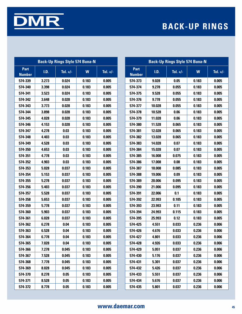
SHAFT SEALS
45www.daemar.com
DMRDMR BaCK-uP rings
Back-up rings style 574 Buna-n
Part number
i.d. Tol. +/- W Tol. +/-
574-339 3.273 0.024 0.183 0.005
574-340 3.398 0.024 0.183 0.005
574-341 3.523 0.024 0.183 0.005
574-342 3.648 0.028 0.183 0.005
574-343 3.773 0.028 0.183 0.005
574-344 3.898 0.028 0.183 0.005
574-345 4.028 0.028 0.183 0.005
574-346 4.153 0.028 0.183 0.005
574-347 4.278 0.03 0.183 0.005
574-348 4.403 0.03 0.183 0.005
574-349 4.528 0.03 0.183 0.005
574-350 4.653 0.03 0.183 0.005
574-351 4.778 0.03 0.183 0.005
574-352 4.903 0.03 0.183 0.005
574-353 5.028 0.037 0.183 0.005
574-354 5.153 0.037 0.183 0.005
574-355 5.278 0.037 0.183 0.005
574-356 5.403 0.037 0.183 0.005
574-357 5.528 0.037 0.183 0.005
574-358 5.653 0.037 0.183 0.005
574-359 5.778 0.037 0.183 0.005
574-360 5.903 0.037 0.183 0.005
574-361 6.028 0.037 0.183 0.005
574-362 6.278 0.04 0.183 0.005
574-363 6.528 0.04 0.183 0.005
574-364 6.778 0.04 0.183 0.005
574-365 7.028 0.04 0.183 0.005
574-366 7.278 0.045 0.183 0.005
574-367 7.528 0.045 0.183 0.005
574-368 7.778 0.045 0.183 0.005
574-369 8.028 0.045 0.183 0.005
574-370 8.278 0.05 0.183 0.005
574-371 8.528 0.05 0.183 0.005
574-372 8.778 0.05 0.183 0.005
Back-up rings style 574 Buna-n
Part number
i.d. Tol. +/- W Tol. +/-
574-373 9.028 0.05 0.183 0.005
574-374 9.278 0.055 0.183 0.005
574-375 9.528 0.055 0.183 0.005
574-376 9.778 0.055 0.183 0.005
574-377 10.028 0.055 0.183 0.005
574-378 10.528 0.06 0.183 0.005
574-379 11.028 0.06 0.183 0.005
574-380 11.528 0.065 0.183 0.005
574-381 12.028 0.065 0.183 0.005
574-382 13.028 0.065 0.183 0.005
574-383 14.028 0.07 0.183 0.005
574-384 15.028 0.07 0.183 0.005
574-385 16.008 0.075 0.183 0.005
574-386 17.008 0.08 0.183 0.005
574-387 18.008 0.085 0.183 0.005
574-388 19.006 0.09 0.183 0.005
574-389 20.006 0.095 0.183 0.005
574-390 21.006 0.095 0.183 0.005
574-391 22.006 0.1 0.183 0.005
574-392 22.993 0.105 0.183 0.005
574-393 23.993 0.11 0.183 0.005
574-394 24.993 0.115 0.183 0.005
574-395 25.993 0.12 0.183 0.005
574-425 4.551 0.033 0.236 0.006
574-426 4.676 0.033 0.236 0.006
574-427 4.801 0.033 0.236 0.006
574-428 4.926 0.033 0.236 0.006
574-429 5.051 0.037 0.236 0.006
574-430 5.176 0.037 0.236 0.006
574-431 5.301 0.037 0.236 0.006
574-432 5.426 0.037 0.236 0.006
574-433 5.551 0.037 0.236 0.006
574-434 5.676 0.037 0.236 0.006
574-435 5.801 0.037 0.236 0.006
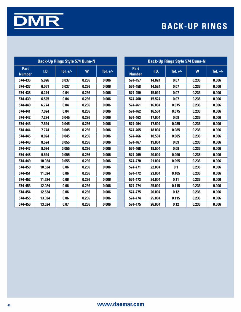
46 www.daemar.com
SHAFT SEALSDMRDMR BaCK-uP rings
Back-up rings style 574 Buna-n
Part number
i.d. Tol. +/- W Tol. +/-
574-436 5.926 0.037 0.236 0.006
574-437 6.051 0.037 0.236 0.006
574-438 6.274 0.04 0.236 0.006
574-439 6.525 0.04 0.236 0.006
574-440 6.774 0.04 0.236 0.006
574-441 7.024 0.04 0.236 0.006
574-442 7.274 0.045 0.236 0.006
574-443 7.524 0.045 0.236 0.006
574-444 7.774 0.045 0.236 0.006
574-445 8.024 0.045 0.236 0.006
574-446 8.524 0.055 0.236 0.006
574-447 9.024 0.055 0.236 0.006
574-448 9.524 0.055 0.236 0.006
574-449 10.024 0.055 0.236 0.006
574-450 10.524 0.06 0.236 0.006
574-451 11.024 0.06 0.236 0.006
574-452 11.524 0.06 0.236 0.006
574-453 12.024 0.06 0.236 0.006
574-454 12.524 0.06 0.236 0.006
574-455 13.024 0.06 0.236 0.006
574-456 13.524 0.07 0.236 0.006
Back-up rings style 574 Buna-n
Part number
i.d. Tol. +/- W Tol. +/-
574-457 14.024 0.07 0.236 0.006
574-458 14.524 0.07 0.236 0.006
574-459 15.024 0.07 0.236 0.006
574-460 15.524 0.07 0.236 0.006
574-461 16.004 0.075 0.236 0.006
574-462 16.504 0.075 0.236 0.006
574-463 17.004 0.08 0.236 0.006
574-464 17.504 0.085 0.236 0.006
574-465 18.004 0.085 0.236 0.006
574-466 18.504 0.085 0.236 0.006
574-467 19.004 0.09 0.236 0.006
574-468 19.504 0.09 0.236 0.006
574-469 20.004 0.096 0.236 0.006
574-470 21.004 0.095 0.236 0.006
574-471 22.004 0.1 0.236 0.006
574-472 23.004 0.105 0.236 0.006
574-473 24.004 0.11 0.236 0.006
574-474 25.004 0.115 0.236 0.006
574-475 26.004 0.12 0.236 0.006
574-474 25.004 0.115 0.236 0.006
574-475 26.004 0.12 0.236 0.006
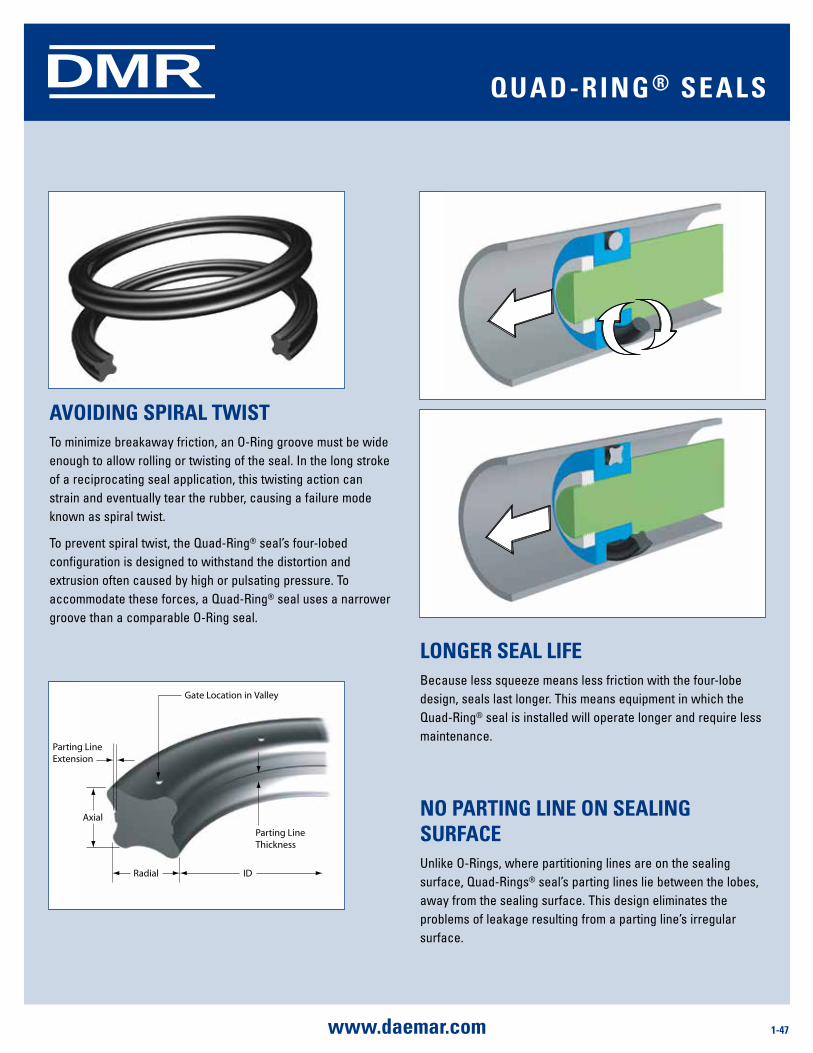
1-47www.daemar.com
DMR
longEr sEal liFEBecause less squeeze means less friction with the four-lobe design, seals last longer. This means equipment in which the Quad-Ring® seal is installed will operate longer and require less maintenance.
no ParTing linE on sEaling surFaCEUnlike O-Rings, where partitioning lines are on the sealing surface, Quad-Rings® seal’s parting lines lie between the lobes, away from the sealing surface. This design eliminates the problems of leakage resulting from a parting line’s irregular surface.
aVoiding sPiral TWisTTo minimize breakaway friction, an O-Ring groove must be wide enough to allow rolling or twisting of the seal. In the long stroke of a reciprocating seal application, this twisting action can strain and eventually tear the rubber, causing a failure mode known as spiral twist.
To prevent spiral twist, the Quad-Ring® seal’s four-lobed configuration is designed to withstand the distortion and extrusion often caused by high or pulsating pressure. To accommodate these forces, a Quad-Ring® seal uses a narrower groove than a comparable O-Ring seal.
Gate Location in Valley
Parting LineThickness
Radial ID
Axial
Parting LineExtension
Quad-ring ® sEals
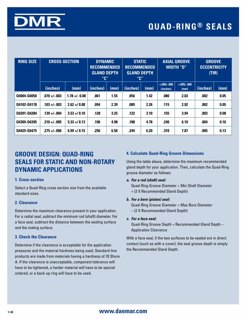
1-48 www.daemar.com
DMR
4. Calculate Quad-ring groove dimensions
Using the table above, determine the maximum recommended gland depth for your application. Then, calculate the Quad-Ring groove diameter as follows:
a. For a rod (shaft) seal: Quad-Ring Groove Diameter = Min Shaft Diameter
+ (2 X Recommended Gland Depth)
b. For a bore (piston) seal: Quad-Ring Groove Diameter = Max Bore Diameter – (2 X Recommended Gland Depth)
c. For a face seal: Quad-Ring Groove Depth = Recommended Gland Depth –
Application Clearance
With a face seal, if the two surfaces to be sealed are in direct contact (such as with a cover), the seal groove depth is simply the Recommended Gland Depth.
grooVE dEsign: Quad-ring sEals For sTaTiC and non-roTary dynamiC aPPliCaTions1. Cross-section
Select a Quad-Ring cross section size from the available standard sizes.
2. Clearance
Determine the maximum clearance present in your application. For a radial seal, subtract the minimum rod (shaft) diameter. For a face seal, subtract the distance between the sealing surface and the mating surface.
3. Check the Clearance
Determine if the clearance is acceptable for the application pressures and the material hardness being used. Standard-line products are made from materials having a hardness of 70 Shore A. If the clearance is unacceptable, component tolerance will have to be tightened, a harder material will have to be special ordered, or a back-up ring will have to be used.
ring siZE Cross-sECTion dynamiC rECommEndEd gland dEPTH
“C”
sTaTiC rECommEndEd gland dEPTH
“C”
aXial grooVE WidTH “d”
grooVE ECCEnTriCiTy
(Tir)
(inches) (mm) (inches) (mm) (inches) (mm)+.005/-.000
(inches) +.005/-.000
(mm) (inches) (mm)
Q4004-Q4050 .070 +/-.003 1.78 +/- 0.08 .061 1.55 .056 1.42 .080 2.03 .002 0.05
Q4102-Q4178 .103 +/-.003 2.62 +/ 0.08 .094 2.39 .089 2.26 .115 2.92 .002 0.05
Q4201-Q4284 .139 +/-.004 3.53 +/ 0.10 .128 3.25 .122 3.10 .155 3.94 .003 0.08
Q4309-Q4395 .210 +/-.005 5.33 +/ 0.13 .196 4.98 .188 4.78 .240 6.10 .004 0.10
Q4425-Q4475 .275 +/-.006 6.99 +/ 0.15 .256 6.50 .244 6.20 .310 7.87 .005 0.13
Quad-ring ® sEals
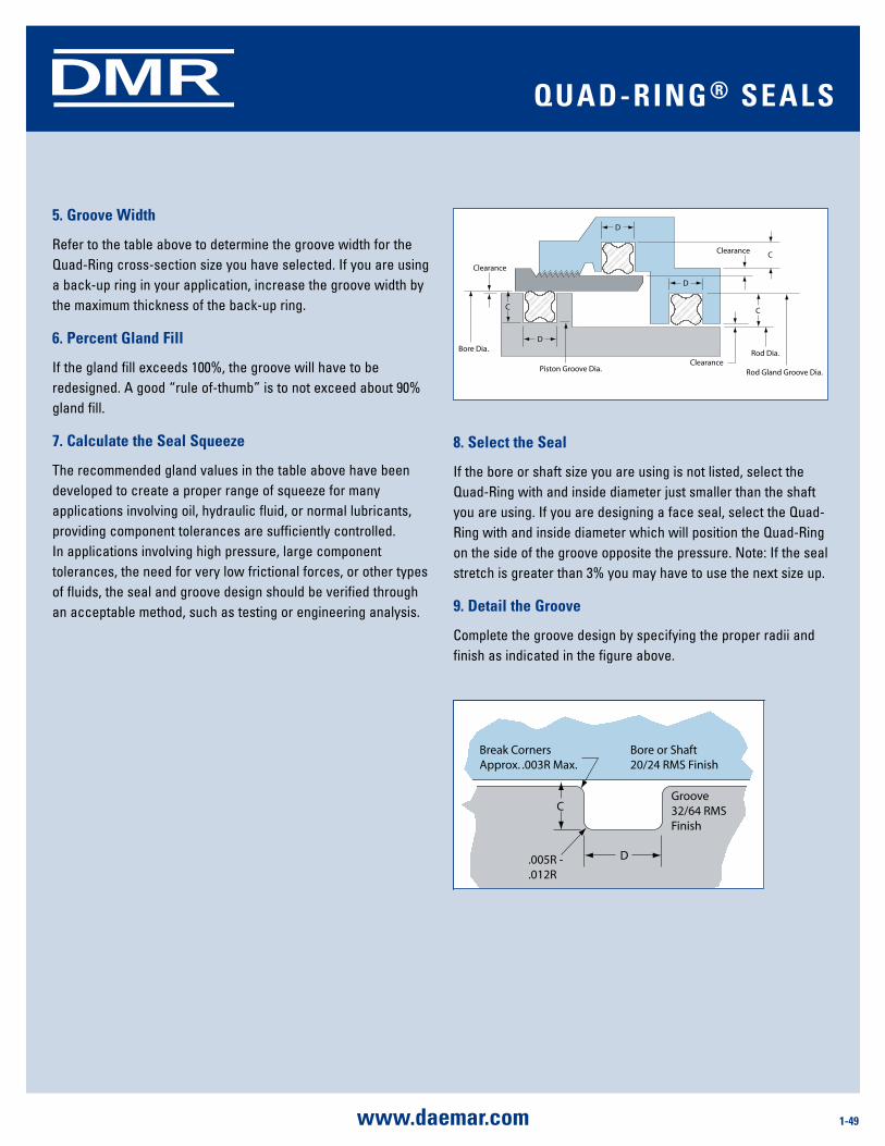
1-49www.daemar.com
DMR
8. select the seal
If the bore or shaft size you are using is not listed, select the Quad-Ring with and inside diameter just smaller than the shaft you are using. If you are designing a face seal, select the Quad-Ring with and inside diameter which will position the Quad-Ring on the side of the groove opposite the pressure. Note: If the seal stretch is greater than 3% you may have to use the next size up.
9. detail the groove
Complete the groove design by specifying the proper radii and finish as indicated in the figure above.
Break CornersApprox. .003R Max.
Groove32/64 RMSFinish
.005R -
.012R
Bore or Shaft20/24 RMS Finish
D
C
Rod Gland Groove Dia.
Clearance
Piston Groove Dia.
Bore Dia.
Clearance
Clearance
D
D
D
Rod Dia.
CC
C
5. groove Width
Refer to the table above to determine the groove width for the Quad-Ring cross-section size you have selected. If you are using a back-up ring in your application, increase the groove width by the maximum thickness of the back-up ring.
6. Percent gland Fill
If the gland fill exceeds 100%, the groove will have to be redesigned. A good “rule of-thumb” is to not exceed about 90% gland fill.
7. Calculate the seal squeeze
The recommended gland values in the table above have been developed to create a proper range of squeeze for many applications involving oil, hydraulic fluid, or normal lubricants, providing component tolerances are sufficiently controlled. In applications involving high pressure, large component tolerances, the need for very low frictional forces, or other types of fluids, the seal and groove design should be verified through an acceptable method, such as testing or engineering analysis.
Quad-ring ® sEals
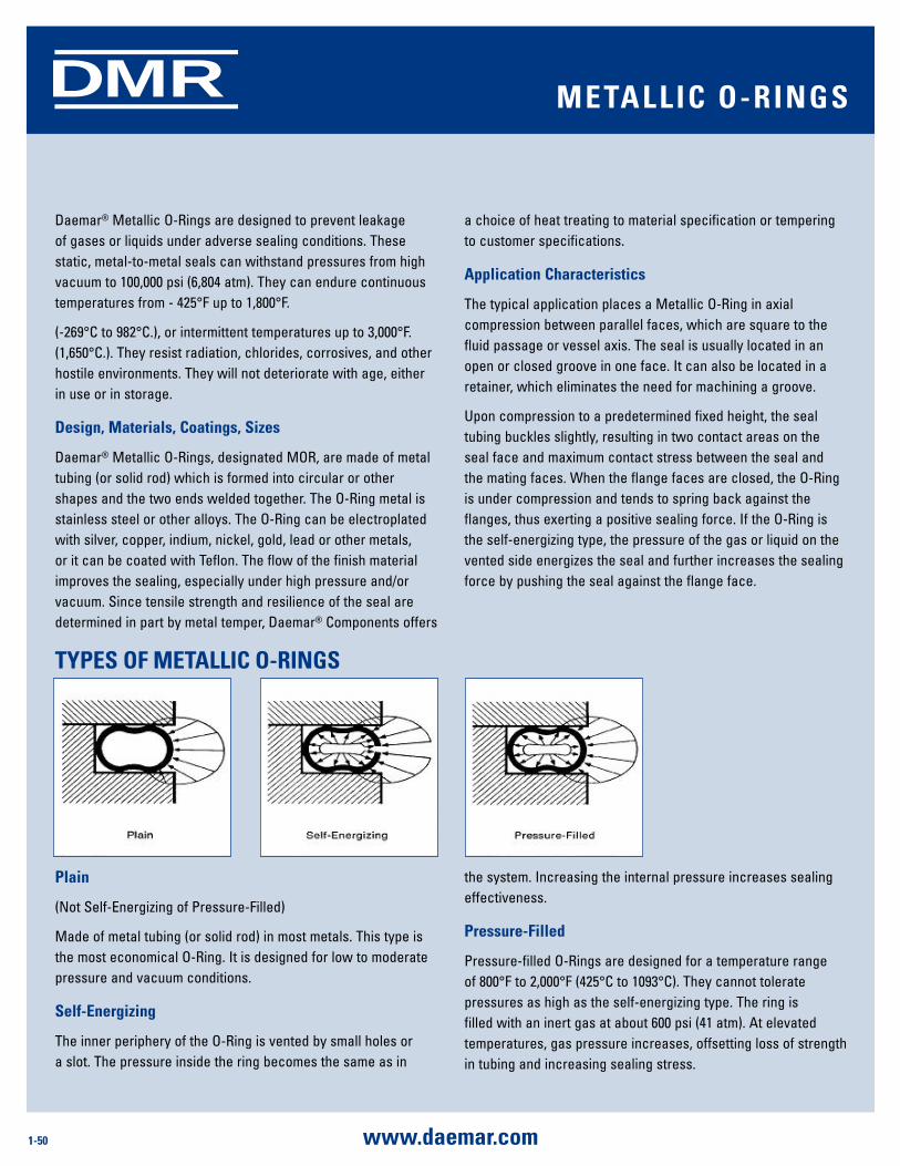
1-50 www.daemar.com
DMR
TyPEs oF mETalliC o-rings
Daemar® Metallic O-Rings are designed to prevent leakage of gases or liquids under adverse sealing conditions. These static, metal-to-metal seals can withstand pressures from high vacuum to 100,000 psi (6,804 atm). They can endure continuous temperatures from - 425°F up to 1,800°F.
(-269°C to 982°C.), or intermittent temperatures up to 3,000°F. (1,650°C.). They resist radiation, chlorides, corrosives, and other hostile environments. They will not deteriorate with age, either in use or in storage.
design, materials, Coatings, sizes
Daemar® Metallic O-Rings, designated MOR, are made of metal tubing (or solid rod) which is formed into circular or other shapes and the two ends welded together. The O-Ring metal is stainless steel or other alloys. The O-Ring can be electroplated with silver, copper, indium, nickel, gold, lead or other metals, or it can be coated with Teflon. The flow of the finish material improves the sealing, especially under high pressure and/or vacuum. Since tensile strength and resilience of the seal are determined in part by metal temper, Daemar® Components offers
a choice of heat treating to material specification or tempering to customer specifications.
application Characteristics
The typical application places a Metallic O-Ring in axial compression between parallel faces, which are square to the fluid passage or vessel axis. The seal is usually located in an open or closed groove in one face. It can also be located in a retainer, which eliminates the need for machining a groove.
Upon compression to a predetermined fixed height, the seal tubing buckles slightly, resulting in two contact areas on the seal face and maximum contact stress between the seal and the mating faces. When the flange faces are closed, the O-Ring is under compression and tends to spring back against the flanges, thus exerting a positive sealing force. If the O-Ring is the self-energizing type, the pressure of the gas or liquid on the vented side energizes the seal and further increases the sealing force by pushing the seal against the flange face.
Plain
(Not Self-Energizing of Pressure-Filled)
Made of metal tubing (or solid rod) in most metals. This type is the most economical O-Ring. It is designed for low to moderate pressure and vacuum conditions.
self-Energizing
The inner periphery of the O-Ring is vented by small holes or a slot. The pressure inside the ring becomes the same as in
the system. Increasing the internal pressure increases sealing effectiveness.
Pressure-Filled
Pressure-filled O-Rings are designed for a temperature range of 800°F to 2,000°F (425°C to 1093°C). They cannot tolerate pressures as high as the self-energizing type. The ring is filled with an inert gas at about 600 psi (41 atm). At elevated temperatures, gas pressure increases, offsetting loss of strength in tubing and increasing sealing stress.
mETalliC o-rings
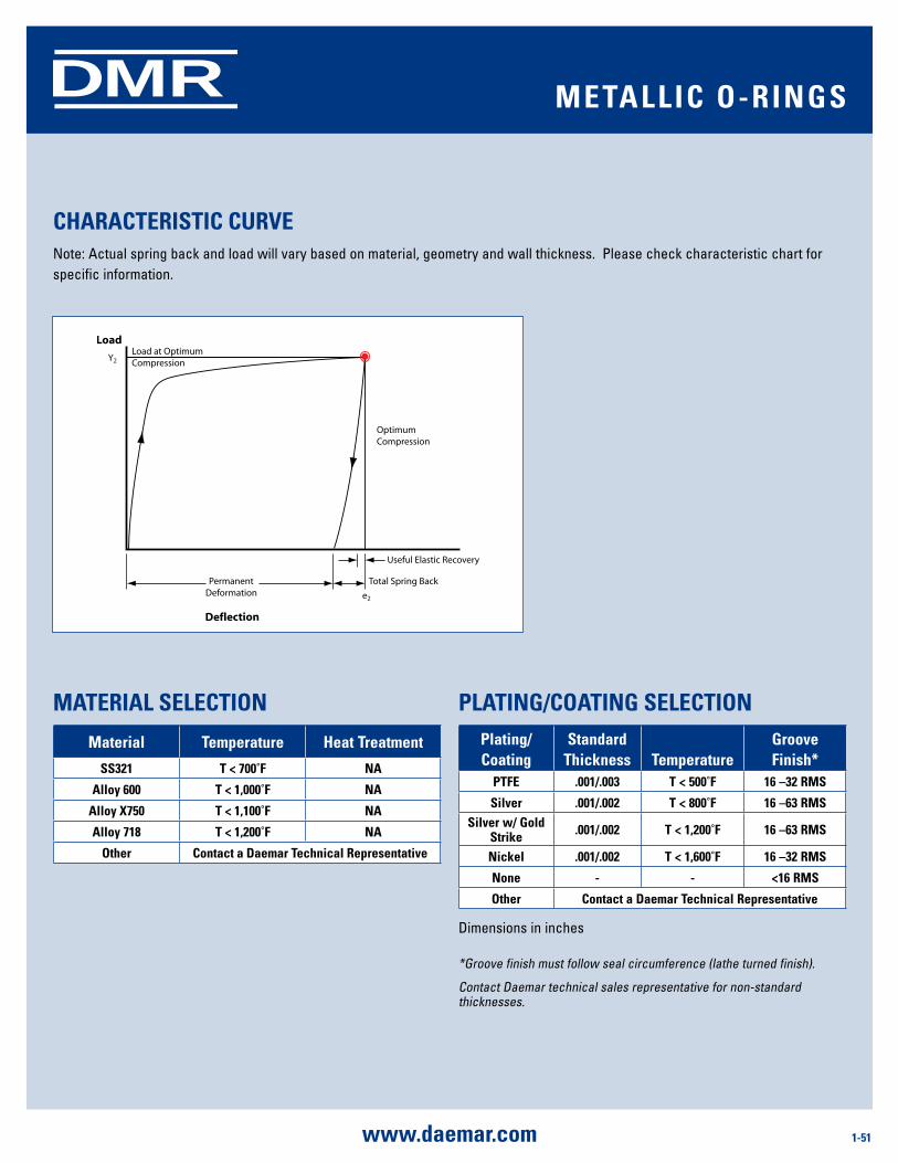
1-51www.daemar.com
DMR
CHaraCTErisTiC CurVENote: Actual spring back and load will vary based on material, geometry and wall thickness. Please check characteristic chart for specific information.
maTErial sElECTion
material Temperature Heat Treatment
ss321 T < 700˚F na
alloy 600 T < 1,000˚F na
alloy X750 T < 1,100˚F na
alloy 718 T < 1,200˚F na
other Contact a daemar Technical representative
PlaTing/CoaTing sElECTionPlating/Coating
standard Thickness Temperature
groove Finish*
PTFE .001/.003 T < 500˚F 16 –32 rms
silver .001/.002 T < 800˚F 16 –63 rmssilver w/ gold
strike .001/.002 T < 1,200˚F 16 –63 rms
nickel .001/.002 T < 1,600˚F 16 –32 rms
none - - <16 rms
other Contact a daemar Technical representative
Dimensions in inches
*Groove finish must follow seal circumference (lathe turned finish).
Contact Daemar technical sales representative for non-standard thicknesses.
mETalliC o-rings
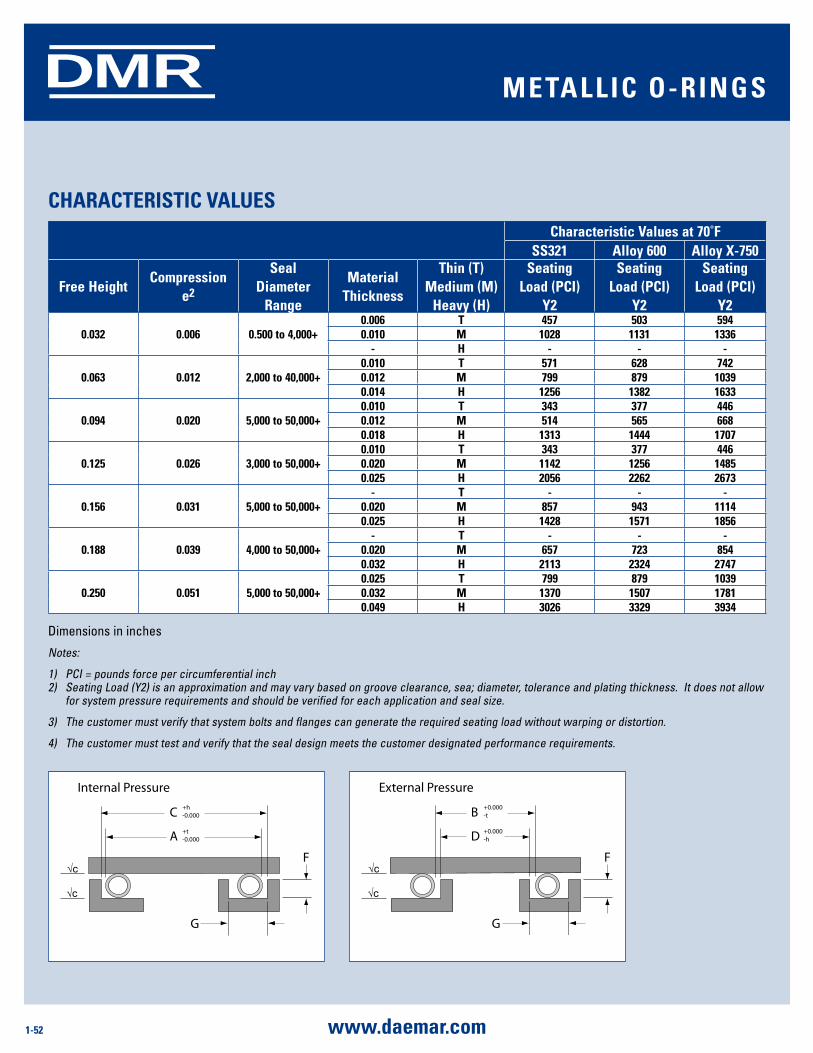
1-52 www.daemar.com
DMR
CHaraCTErisTiC ValuEsCharacteristic Values at 70˚F
ss321 alloy 600 alloy X-750
Free HeightCompression
e2
seal diameter
range
material Thickness
Thin (T) medium (m)
Heavy (H)
seating load (PCi)
y2
seating load (PCi)
y2
seating load (PCi)
y2
0.032 0.006 0.500 to 4,000+0.006 T 457 503 5940.010 m 1028 1131 1336
- H - - -
0.063 0.012 2,000 to 40,000+0.010 T 571 628 7420.012 m 799 879 10390.014 H 1256 1382 1633
0.094 0.020 5,000 to 50,000+0.010 T 343 377 4460.012 m 514 565 6680.018 H 1313 1444 1707
0.125 0.026 3,000 to 50,000+0.010 T 343 377 4460.020 m 1142 1256 14850.025 H 2056 2262 2673
0.156 0.031 5,000 to 50,000+- T - - -
0.020 m 857 943 11140.025 H 1428 1571 1856
0.188 0.039 4,000 to 50,000+- T - - -
0.020 m 657 723 8540.032 H 2113 2324 2747
0.250 0.051 5,000 to 50,000+0.025 T 799 879 10390.032 m 1370 1507 17810.049 H 3026 3329 3934
Dimensions in inches
Notes:
1) PCI = pounds force per circumferential inch 2) Seating Load (Y2) is an approximation and may vary based on groove clearance, sea; diameter, tolerance and plating thickness. It does not allow
for system pressure requirements and should be verified for each application and seal size.
3) The customer must verify that system bolts and flanges can generate the required seating load without warping or distortion.
4) The customer must test and verify that the seal design meets the customer designated performance requirements.
G
C
F
Internal Pressure
√c
+h-0.000
A +t-0.000
√c
G
B
F
External Pressure
√c
+0.000-t
D +0.000-h
√c
G
C
F
Internal Pressure
√c
+h-0.000
A +t-0.000
√c
G
B
F
External Pressure
√c
+0.000-t
D +0.000-h
√c
mETalliC o-rings

1-53www.daemar.com
DMR
sEal and grooVE siZing CalCulaTionsThe equations below can be used for basic groove calculations. Applications that have significant thermal expansion may require additional clearance. Please contact Daemar for design assistance.
determining seal diameter:
internal External
A=C-X-2Pmax B = D+X+2Pmax
determining seal diameter:
internal External
C=A+X+2Pmax D = B-X-2Pmax
Tolerancing: See Chart
Where:
A = Seal Outer DiameterB = Seal Inner DiameterC = Groove Outer DiameterD = Groove Inner DiameterPmax = Maximum Plating or Coating ThicknessX = Diametrical Clearance
groove Finish √ c: See Plating/Coating Section
sEal and grooVE dimEnsions
seal groove
Free Heightseal diameter
range seal Tolerance tdiametrical Clearance x
groove Tolerance h groove depth F
groove Width (min.) g
0.032 0.500 to 4.000 0.005 0.006 0.004 0.026±0.001 0.055
0.063 0.500 to 10.000 0.005 0.006 0.004 0.051±0.001 0.090
0.094 1.000 to 20.000 0.005 0.008 0.004 0.073±0.002 0.125
0.125 2.000 to 40.000 0.005 0.008 0.004 0.099±0.002 0.160
0.156 3.000 to 50.000+ 0.005 0.014 0.006 0.125±0.002 0.200
0.188 4.000 to 50.000+ 0.005 0.014 0.006 0.149±0.002 0.250
0.250 5.000 to 50.000+ 0.008 0.019 0.008 0.199±0.002 0.350
Dimensions in inches
mETalliC o-rings
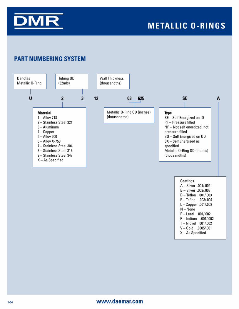
1-54 www.daemar.com
DMR
ParT numBEring sysTEm
Tubing OD (32nds)Denotes Metallic O-RingWall Thickness(thousandths)
CoatingsA – Silver .001/.002B – Silver .002/.003D – Teflon .001/.003E – Teflon .003/.004L – Copper .001/.002N – NoneP – Lead .001/.002R – Indium .001/.002T – Nickel .001/.002V – Gold .0005/.001X – As Specified
Materials1 – Alloy 7182 – Stainless Steel 3213 – Aluminum4 – Copper5 – Alloy 6006 – Alloy X-7507- Stainless Steel 3048 – Stainless Steel 3169 - Stainless Steel 347X – As SpecifiedTypeSE – Self Energized on IDPF – Pressure filledNP – Not self energized, not pressure filledSO – Self Energized on ODSX – Self Energized as specifiedMetallic O-Ring OD (inches) (thousandths)U 2 3 12 03 625 SE A
Denotes Metallic O-Ring
Tubing OD (32nds)
Wall Thickness(thousandths)
Metallic O-Ring OD (inches) (thousandths)
CoatingsA – Silver .001/.002B – Silver .002/.003D – Teflon .001/.003E – Teflon .003/.004L – Copper .001/.002N – NoneP – Lead .001/.002R – Indium .001/.002T – Nickel .001/.002V – Gold .0005/.001X – As Specified
TypeSE – Self Energized on IDPF – Pressure filledNP – Not self energized, not pressure filledSO – Self Energized on ODSX – Self Energized as specifiedMetallic O-Ring OD (inches) (thousandths)
Material1 – Alloy 7182 – Stainless Steel 3213 – Aluminum4 – Copper5 – Alloy 6006 – Alloy X-7507 – Stainless Steel 3048 – Stainless Steel 3169 – Stainless Steel 347X – As Specified
U 2 3 12 03 625 SE A
mETalliC o-rings
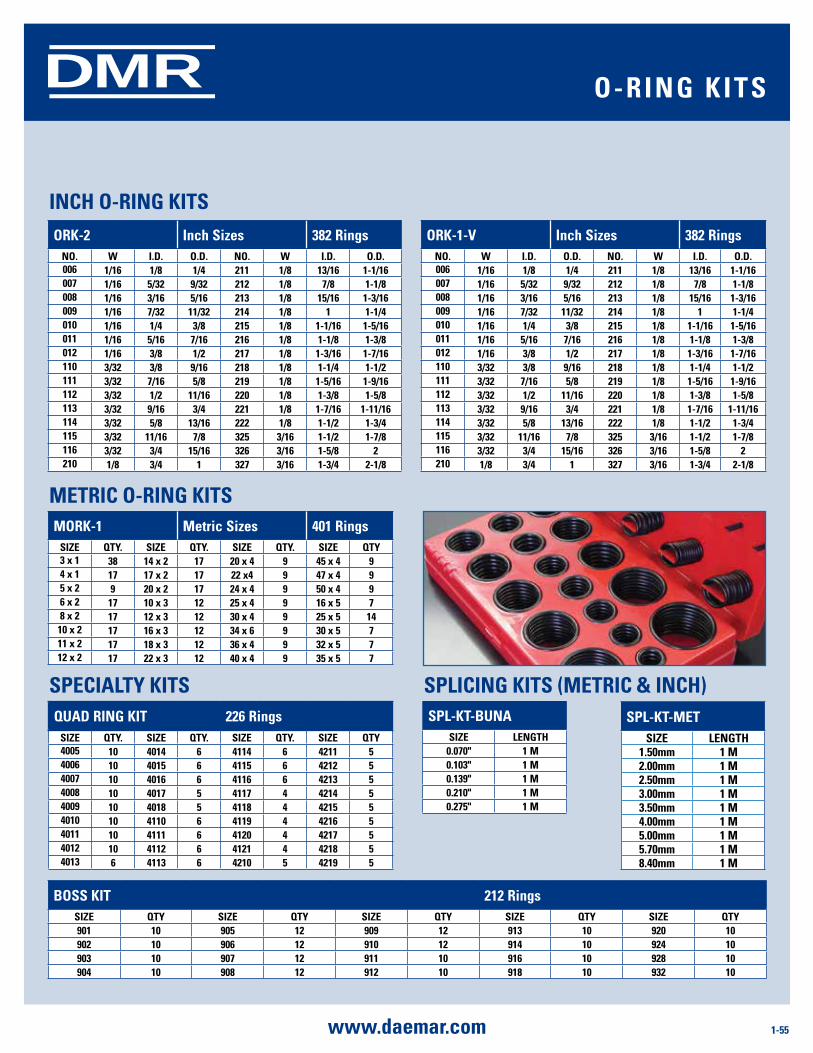
1-55www.daemar.com
DMR
orK-2 inch sizes 382 ringsno. W i.d. o.d. no. W i.d. o.d.006 1/16 1/8 1/4 211 1/8 13/16 1-1/16007 1/16 5/32 9/32 212 1/8 7/8 1-1/8008 1/16 3/16 5/16 213 1/8 15/16 1-3/16009 1/16 7/32 11/32 214 1/8 1 1-1/4010 1/16 1/4 3/8 215 1/8 1-1/16 1-5/16011 1/16 5/16 7/16 216 1/8 1-1/8 1-3/8012 1/16 3/8 1/2 217 1/8 1-3/16 1-7/16110 3/32 3/8 9/16 218 1/8 1-1/4 1-1/2111 3/32 7/16 5/8 219 1/8 1-5/16 1-9/16112 3/32 1/2 11/16 220 1/8 1-3/8 1-5/8113 3/32 9/16 3/4 221 1/8 1-7/16 1-11/16114 3/32 5/8 13/16 222 1/8 1-1/2 1-3/4115 3/32 11/16 7/8 325 3/16 1-1/2 1-7/8116 3/32 3/4 15/16 326 3/16 1-5/8 2210 1/8 3/4 1 327 3/16 1-3/4 2-1/8
sPl-KT-Buna siZE lEngTH
0.070" 1 m0.103" 1 m0.139" 1 m0.210" 1 m0.275" 1 m
sPl-KT-mET siZE lEngTH
1.50mm 1 m2.00mm 1 m2.50mm 1 m3.00mm 1 m3.50mm 1 m4.00mm 1 m5.00mm 1 m5.70mm 1 m8.40mm 1 m
orK-1-V inch sizes 382 ringsno. W i.d. o.d. no. W i.d. o.d.006 1/16 1/8 1/4 211 1/8 13/16 1-1/16007 1/16 5/32 9/32 212 1/8 7/8 1-1/8008 1/16 3/16 5/16 213 1/8 15/16 1-3/16009 1/16 7/32 11/32 214 1/8 1 1-1/4010 1/16 1/4 3/8 215 1/8 1-1/16 1-5/16011 1/16 5/16 7/16 216 1/8 1-1/8 1-3/8012 1/16 3/8 1/2 217 1/8 1-3/16 1-7/16110 3/32 3/8 9/16 218 1/8 1-1/4 1-1/2111 3/32 7/16 5/8 219 1/8 1-5/16 1-9/16112 3/32 1/2 11/16 220 1/8 1-3/8 1-5/8113 3/32 9/16 3/4 221 1/8 1-7/16 1-11/16114 3/32 5/8 13/16 222 1/8 1-1/2 1-3/4115 3/32 11/16 7/8 325 3/16 1-1/2 1-7/8116 3/32 3/4 15/16 326 3/16 1-5/8 2210 1/8 3/4 1 327 3/16 1-3/4 2-1/8
morK-1 metric sizes 401 ringssiZE QTy. siZE QTy. siZE QTy. siZE QTy3 x 1 38 14 x 2 17 20 x 4 9 45 x 4 94 x 1 17 17 x 2 17 22 x4 9 47 x 4 95 x 2 9 20 x 2 17 24 x 4 9 50 x 4 96 x 2 17 10 x 3 12 25 x 4 9 16 x 5 78 x 2 17 12 x 3 12 30 x 4 9 25 x 5 14
10 x 2 17 16 x 3 12 34 x 6 9 30 x 5 711 x 2 17 18 x 3 12 36 x 4 9 32 x 5 712 x 2 17 22 x 3 12 40 x 4 9 35 x 5 7
Quad ring KiT 226 rings siZE QTy. siZE QTy. siZE QTy. siZE QTy4005 10 4014 6 4114 6 4211 54006 10 4015 6 4115 6 4212 54007 10 4016 6 4116 6 4213 54008 10 4017 5 4117 4 4214 54009 10 4018 5 4118 4 4215 54010 10 4110 6 4119 4 4216 54011 10 4111 6 4120 4 4217 54012 10 4112 6 4121 4 4218 54013 6 4113 6 4210 5 4219 5
inCH o-ring KiTs
mETriC o-ring KiTs
sPliCing KiTs (mETriC & inCH)
Boss KiT 212 ringssiZE QTy siZE QTy siZE QTy siZE QTy siZE QTy901 10 905 12 909 12 913 10 920 10902 10 906 12 910 12 914 10 924 10903 10 907 12 911 10 916 10 928 10904 10 908 12 912 10 918 10 932 10
sPECialTy KiTs
o-ring KiTs
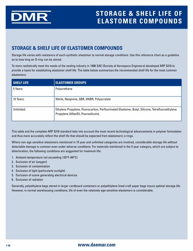
1-56 www.daemar.com
DMR sToragE & sHElF liFE oF ElasTomEr ComPounds
sToragE & sHElF liFE oF ElasTomEr ComPoundsStorage life varies with resistance of each synthetic elastomer to normal storage conditions. Use this reference chart as a guideline as to how long an O-ring can be stored.
To more realistically meet the needs of the sealing industry in 1998 SAE (Society of Aerospace Engineers) developed ARP 5316 to provide a basis for establishing elastomer shelf life. The table below summarizes the recommended shelf life for the most common elastomers:
sHElF liFE ElasTomEr grouPs
5 Years: Polyurethane
15 Years: Nitrile, Neoprene, SBR, HNBR, Polyacrylate
Unlimited: Ethylene Propylene, Fluorocarbon, Perfluorinated Elastomer, Butyl, Silicone, Tetrafluoroethylene Propylene (Aflas®), Fluorosilicone.
This table and the complete ARP 5316 standard take into account the most recent technological advancements in polymer formulation and thus more accurately reflect the shelf life that should be expected from elastomeric o-rings.
Where non-age sensitive elastomers mentioned in 15 year and unlimited categories are involved, considerable storage life without detectable damage is common even under adverse conditions. For materials mentioned in the 5 year category, which are subject to deterioration, the following conditions are suggested for maximum life:
1. Ambient temperature not exceeding 120°F (49°C) 2. Exclusion of air (oxygen) 3. Exclusion of contamination 4. Exclusion of light (particularly sunlight) 5. Exclusion of ozone generating electrical devices 6. Exclusion of radiation
Generally, polyethylene bags stored in larger cardboard containers or polyethlylene lined craft paper bags insure optimal storage life. However, in normal warehousing conditions, life of even the relatively age-sensitive elastomers is considerable.
1-57www.daemar.com
DMR
Like any device subject to judgment in design, or to human error during installation, O-ring seals are liable to failure. The following brief summary of O-ring failure patterns is intended to give the designer/engineer a brief overview of the more common types of failure and a listing of recommended corrective actions. While there are a number of different types and causes to seal failure, we intend here to cover only the types encountered most frequently.
WHy an o-ring FailsThe failure of an O-ring in service can usually be attributed to a combination of causes. Most often, with the absence of one of the conditions existing at the time of failure, the O-ring would have continued performing. It is important to maximize sealing life and reliability by reducing the probability of seal failure at the onset by the use of good design practices, proper compound selection, pre-production testing, and continued education and training of assembly personnel.
EXTrusion and niBBlingExtrusion and nibbling of the O-ring is a primary cause of seal failure in dynamic applications such as Hydraulic Rod and Piston seals. This form of failure may also be found from time to time in static applications subject to high pressure pulsing which causes the clearance gap of the mating flanges to open and close, trapping the O-ring between the mating surfaces.
Failure analysis
In general, EXTRUSION and NIBBLING are caused by one or more of the following conditions:
I. Excessive clearances.2. High pressure (in excess of system design or high pressure
excursions).3. O-ring material too soft.4. Degradation (swelling, softening, shrinking, cracking, etc.) of
O-ring material by system fluid. 5. Irregular clearance gaps caused by eccentricity.6. Increase in clearance gaps due to excessive system pressure.7. Improper machining of O-ring gland (sharp edges).8. Improper size (too large) O-ring installed causing excessive
filling of groove.
Prevention/Correction
Suggested solutions to the causes of Extrusion and Nibbling listed above are:
1. Decrease clearance by reducing machining tolerances.2. Use back-up devices. 3. Check O-ring material compatibility with system fluid.4. Increase rigidity of metal components.5. Replace current O-ring with a harder O-ring.6. Break sharp edges of gland to a minimum radius 0.002 inches.7. Insure installation of proper size O-rings.
identification of Extrusion Failure
A typical example of O-ring extrusion is when edges of the ring on the low pressure or downstream side of the gland exhibit a “chewed” or “chipped” appearance.
In an O-ring that has failed due to nibbling, it may have the appearance that many small pieces have been removed from the low pressure side. In some forms of extrusion, more than 50% of the O-ring may be destroyed before catastrophic leakage is observed.
idEnTiFying o-ring FailurE
1-58 www.daemar.com
DMR
ComPrEssion sETProbably the most common cause of O-ring failure is compression set. An effective O-ring seal requires a continuous “seal line”
between the sealed surfaces. The establishment of this “seal line”
is a function of gland design and seal cross-section which determines the correct amount of squeeze (compression) on the O-ring to maintain seal integrity without excessive deformation of the seal element. There are a number of factors that can contribute to compression set failure of an O-ring seal. They are listed below.
Failure analysis
In general, COMPRESSION SET is caused by one or more of the following conditions:
1. Selection of O-ring material with inherently poor compression set properties.
2. Improper gland design.3. Excessive temperature developed causing the O-ring to
harden and lose its elastic properties.4. Volume swell of the O-ring due to system fluid.5. Excessive squeeze due to over tightening of adjustable
glands.6. Incomplete curing (vulcanization) of O-ring material during
production.7. Introduction of fluid incompatible with O-ring material.
Prevention/correction
Suggested solutions to the causes of compression set are:
1. Use “LOW-SET” O-ring material whenever possible.2. Select O-ring material compatible with intended service
conditions.3. Reduce system operating temperature.4. Check frictional heat build-up at seal interface and reduce if
excessive.5. Inspect incoming O-ring shipments for correct physical
properties.
idEnTiFiCaTion oF ComPrEssion sET FailurE
A typical example of classic O-ring compression set in simplistic terms: the O-ring ceases to be “O” shaped and is permanently deformed into a flat sided oval, the flat sides of which were the original seal interface and under compression before failure.
sPiral FailurESpiral failure of an O-ring is often found on long stroke hydraulic piston seals and to a lesser degree on rod seals. This type of O-ring failure is caused when the seal becomes “hung-up’’ at one point on its diameter (against the cylinder wall) and slides and rolls at the same time. The resultant twisting of the O-ring as the sealed device is cycled finally causes the seal to develop a series of deep spiral cuts (usually at a 45° angle) on the surface of the seal.
Failure analysis
As stated above, spiral failure is generally caused by an O-ring both sliding and rolling at the same time. Conditions which may cause this to occur are:
1. Eccentric components.2. Wide clearance combined with side loads.3. Uneven surface finishes.4. Inadequate or improper lubrication.5. O-ring too soft.6. Stroke speed (usually too slow).7. Improper installation (O-ring pinched or rolled).
Prevention/correction
Suggested solutions to the causes of spiral failure are as follows:
1. Improve surface finish of sealed assembly at dynamic interface (Cylinder Bore, Piston Rod).
2. Check for out-of-round components (Cylinder Bores especially).
3. Provide proper lubrication.4. Replace with a harder O-ring.5. Consider use of alternate seal shapes
idEnTiFying o-ring FailurE
1-59www.daemar.com
DMR
idEnTiFiCaTion oF sPiral FailurE
You will see the typical cuts that gave this type of O-ring failure its name.
EXPlosiVE dEComPrEssionWith the advent of the space age we are seeing this type of O-ring failure with increasing frequency. It might be termed O-ring embolism, in that after a period of service under high pressure gas, when the pressure is reduced too rapidly, the gas trapped within the internal structure of the O-ring expands rapidly, causing small ruptures or pitting on the O-ring surface.
Failure analysis
Explosive decompression, or gas expansion rupture is caused by high pressure gas trapped within the internal structure of the elastomeric seal element. Rapid decrease in system pressure causes the trapped gas to expand to match the external pressure and this expansion causes blisters and ruptures on the seal surface. If the volume of trapped gas is small, the blisters may recede as the pressure is equalized with little effect on seal integrity. Excessive trapped gas may cause total destruction of the seal.
Prevention/correction
Suggested solutions to explosive decompression are:
1. Increase decompression time to allow trapped gas to work out of seal material.
2. Choose a seal material with good resistance to explosive decompression.
3. If problem persists and pressures are very high consider use of metallic ‘O’ Ring or ‘C’ Ring.
idEnTiFiCaTion oF EXPlosiVE dEComPrEssion FailurE
The seal subjected to explosive decompression will often exhibit small pits or blisters on its surface. In severe cases, examination of the internal structure of the O-ring will reveal other splits and fissures.
aBrasionAnother rather common type of O-ring failure is abrasion. This usually is found only in dynamic seals subject either to reciprocating, oscillating, or rotary motion. Possible causes of O-ring abrasion are listed below.
Failure analysis
In general, abrasion of O-ring seals is caused by one or more of the following:
1. Improper finish of the surface in dynamic contact with the O-ring. This surface finish may be too rough, acting as an abrasive, or too smooth, causing inadequate lubrication due to inability of surface to hold lubricant.2. Improper lubrication provided by system fluid.3. Excessive temperatures.4. Contamination of system fluid by abrasive particles.
Prevention and Correction
Suggested solutions to problems caused by abrasion are:1. Use proper surface finish 2. Provide adequate lubrication by use of proper system fluid.3. Consider use of internally lubricated O-rings to reduce friction and wear.4. Check for contamination of fluid and eliminate source. Install filters if necessary.5. Consider changing to an O-ring material with improved abrasion resistance.
idEnTiFiCaTion oF aBrasion FailurE
The O-ring that has failed due to wear through abrasion usually exhibits a flat area on the side of the seal which was in contact with the dynamic surface. Frequently there will be wear lines on this flat surface parallel to the direction of motion. Abrasion failure may be differentiated from compression set failure in that with abrasion, only one side of the O-ring will be flat or worn while with compression set failure, both sides of the O-ring are equally deformed.
idEnTiFying o-ring FailurE
1-60 www.daemar.com
DMR
insTallaTion damagEMany O-ring failures can be directly attributed to improper installation. In spite of its simple appearance, the O-ring is a precision device requiring care during installation. Some of the more frequent causes of O-ring failure due to careless handling are listed below.
Failure analysis
Damage to an O-ring during installation can occur when:
1. There are sharp corners on mating metal components such as the O-ring gland or threads over which the O-ring must pass during assembly.
2. Insufficient lead-in chamfer.
3. Blind grooves in multi-port valves.
4. Oversize O-ring on piston seal application.
5. Under size O-ring on rod application.
6. O-ring twisted/pinched during installation.
7. O-ring not properly lubricated before installation.
8. O-ring dirty upon installation.
9. O-ring gland and/or other surfaces over which O-ring must pass during assembly contaminated with metal particles.
10. General carelessness.
Prevention and Correction
Probably the best way to prevent damage to O-rings during installation is the use of good common sense. There are some specific solutions which are listed below:
1. Break all sharp edges on metal components.
2. Provide a 20 degree lead-in chamfer.
3. Check all components for cleanliness before installation.
4. Tape all threads over which the O-ring will pass.
5. Use an O-ring lubricant
6. Double check O-ring to insure correct size and material.
7. Be CAREFUL.
idEnTiFiCaTion oF insTallaTion FailurE
It is difficult to properly illustrate the many possible results of installation failure. One of the more common failure modes is the “Skiving’’ of the O-ring surface due to cutting by metal components. Those cuts are usually very clean as if made with a very sharp knife. Another indication of bad installation will be small cuts or notches on the O-ring. In almost all cases, the damage will appear on the surface of the O-ring away from the bottom of the O-ring groove.
oTHEr CausEs oF o-ring FailurEAlthough not illustrated here, there are several other possible causes of O-ring failure. They are:
1. Weather and ozone degradation.
2. Heat aging and oxidation.
3. Loss of plasticizer.
idEnTiFying o-ring FailurE

slidE
sEal
ProTECT
alig
n
rETain
dryslide™
Fiber-lube™
linear motion
Powdered metal
solid metal
oil seals
o-ring Kits
dmr Bearing isolators
V-rings
shaft repair sleeves
rotor Clip®
spirolox®
ring masters®
rotor Clamp®
retaining ring Kits & Packs
Tapered Caps and Plugs
Caps
Plugs
Finishing
Electronics
Woodruff Keys
slotted shim
slotted shim Kits
shim stock rolls
Keystock
www.daemar.com
www.daemar.com
www.daemar.com
DMRTM
C0B-003
daEmar® inC.861 CRANBERRY COURTOAKVILLE, ON L6L 6J7
PH/905/847/6500FX/905/847/6943TF/800/387/7115
TFX/800/269/[email protected]
daEmar® inC.548 MELOCHE
DORVAL, QC H9P 2T2PH/514/636/3113FX/514/633/1206TF/800/361/6826
daEmar® inC.4472-97TH STREET
EDMONTON, AB T6E 5R9PH/780/435/8899FX/780/435/9090TF/800/214/9590
daEmar® inC.1635 Lakes Parkway, Suite F
Lawrencevile, GA 30043PH/770/953/4710FX/770/953/4711TF/877/432/3627