Embed Size (px)
Citation preview

O UNLIMITE.- .. '/SU.DC. No
A.U.W.E T ech. Not. $
-534-S 21/75621 MAY 19755 3 94 .3 ,2
t24-1Copy No.
1 NOISE IN BROAD- BAND HYDROPHONE
\.b
S~BY
D. STANSFIELD
COPY AVAILABLE TO DOG DOES NOT I IsiPERMIT FULLY LEGIBLE PRODUCTIONfi g
C
0
Ui
zt• ADMIRALTY U•NDERWATER WEAPONS ESTABLISHMENT
'aPORTLAND
Best Available Copy C.9o76, ,I 4N 1976|
~ ~~~~~~UNLIMI/TE DI A-'"'-T '• • •••• • -'

The viewý expresed herein do not necessarily represent che considered opinion of theissuing establishment and must nor be taken to define Ministry of Defence (Naval) or
Depanrmental policy.
__ __AMENDETaI -- , , l I I , I ., S, I •
-i
.Wt.
1-L . , II••= , ......... 1
\* •-Ai;• ......
-- '
•: I I I I I I I I I I I I I I I I I I I

UNCLASSIFIED
SUNLIMITED0
0U.D-_ o A.U.WE. Tech. Note 521/75
z s34.447 : MAY 1975
S621 - 395-62 '204. 0:S534 837-6 Copy No.
NOISE IN BROAD-BAND HYDROPHONES
D. STANSFIELD
IIIL
z4 (L-apl e 'rcont Cover for fii-ming purposer&)
ADMIRALTY UNDERWATER WEAPONS ESTABLISHMENT
iW PORTLAND
UNCLASSIFIED
I-ON L I M I T E r,

-. r i . .... > ' , .,-,.:rT,--¶'.. ,. I
"-- ------ --------------.
T,.2fl4 " I- .. I F
ii • . ..... -- • --; .
• -_
- -
____._ /u C Or• i75t .. ..

R vflý'A P Y
Tmp -''t 'r f" .[d,' p.n D,-s ,,.i
IV S P HF2 '," •A L i{f ýR C HO 0 ?E'S
r
vi .EEP IOAL ETR PHNE 3 0
VIT RELATONTc;;TP SENia]. ACCELERAPION AIW, PRESSURE RE.SPOLFSES 52
VIlT CONCLU,,CION"
A c im o, edLeme int e
R3Et-2 CES 62

: LbSTRATWIONS
1 Ideal hydrcphoa itteace
2 Uydrophoce with added loss
3 Hydraophone 4ukvvalft Circuit
4(a) Equivalent thermal noise pressure for hydrophone with parallel resistor
4(b) £quivalant thermal uoise pcesanre t* c t hy._ophone with parallel rsistor5(a) Value& of (106/ 11 ) - i2 vs
5(b) Nomogra for calculatimO of (%/ke2 ) FCFI
6(a) kEquivaltet thermal noise pressure for hydrophone with tan 6 losses
6(b) Equivalont thermal noi" pressure for hydrophon wi•h tan looSyr
7 V&lues of (10 /F 2.7) ve F
8 Diagrem of piston-type hydrvphone
9 Approximate values of (a C), vs resonancs freqxwncy for piston hydruphmies
10 Amplifier Sud thermal noise vs frequency for three hydrophoct designs
Li Values of (a/C) vs PF for spherical hydrophoses
12 Mchanical representation of hydrophas lomat
13 Acceleration response of hydrophoceEffect of cancelling for nominally balanced hish-% eleamt
•1 14 Acceleration responma of hydrophoce
Effect of cancelling for nominally balanced lov-Q% dout
15 Accoleratioc responseEffect of unbalance for high-_(? eiemat
16 Acceleration responseSi• Effect of unbalance for low-%Q eleint
,7 Pressure response of balanced elemmt
18 Effect of mass unbalanc oan pressure response
19 Acceler•tioc/Prossure response
20 Relation between particle accolertion and pressure in water
A•

/ ,
ILLUS'.RATIONrs (coat 1d)
22 Aaplifiar and titrisi nOise backgnnumd

JMT 1 BUTION'
. ... . .. t. .* .*. . *. .
*** o. o. t. t. oo to to * 3 it 42

NOISE IN BRD.D-RAND HYROPiOitS
SUMMARY
"The sources of noise in underwater electro-acaustic hydruphoaes
are considered with p:rticuler referenc: to piezoalectric piston-type
elemnts. Expre~asons are derived for the various comtributions. and
their influence on hydrophone design for broad-band reception it)
discussed.
It is shown tlat mteasurement of ambient noise levels do.n to Sea
State 1/2 equivalent is possible up to 70 kliz with a correctly designed
hydrophone and a low noise amplifier with sufficiently high input
impedance. M.easure.-.ents down to this level are more readily carried
out with a spherical hydrophone than with a ptston hydrophone in a
1 baff'A:. The hydrophone paramaters of greatest importance are the
resonance frequency, coupling coefficient, and hydrophone sensitivity.
It is important also to avoid mechanical resonances of the hydrophone
mounting.
1t.1I
-I:'.2I A} :A• •[T 3L • i
"It-,f

NOISE IN BRLOAD)-BAND d7YDROfllOESS
This report discuses the various sources of noise in the output of
pressure hydrophoces, and th4tir Influucar on the performace and design
of broad-band receiver. The contributions considered include:
a. thermal woise
b. awbient sea niase
C. awlif tar noise
d. noise dus to mounting vibration
and these are related to the pressure sensitivity of the hydropha• e
ol.nant itself.
1Cotideration is given mainly to ly-frequency piston-type hydro-
phounis ot a balanced ('acelerat<ou-cancelling') design, but the
rimatiocahips are also valid fur unbalanced design-. and similar
principle. Vpiy to other form, of construction.
I X1. THERMAL NOISE
Any resistor at a finite teprarure has across it voltage fluctua-
cions which are known as thermal noise. A hydrophons imersed in the
i.

• - rtnponmi LO 2?M-sure fluctuatio-s In the mtdiu whic.h arlse
simalarly f rot thertml agitation of the medium itself. 4i1lae
(RAIf 1) has showr that this thermal noite pressure in a I Rz band (PT)
is given by
I Iw-here K - Boltz- a~? constant (1.38 x 10O' J/deg K)
p - deasity of the medium
c - s•peedd of sound in the mdium
I - wavelength of sound in the medium at the relevant frequency (f)
T - temperature in degrees Kelv-n.
P It is of interest to express this noise pressure level in term of the
noise voltage output generated by a hydrophone iersed in the sea and
subjected to the.e pressure fluctuations. This requires a knowledge of
the hydrophone sensitivity of the device, whiLc mawy be derIvnd as follows,
The acoustic pressure (p) at a point dietant r from a *mall olnai-
directional source is given by the expression for the total acoustic
4 power:
2 2 2AP- 47rr 2 - i 2 Rn (r >>») (2)pC s o
i iI

ýiwflreU we*an square input current
R -rvsiative COUO t of the Loput impedanc•eII- e ect:o-ecoustic efficiency.
Th-u, the current projector sensitivity (S 1 ) i6 given by
.3
1 2
By the reciprocity theorem, the open-circuit hydrophon sensitivity (M)
is related to the projector asnsitivity by
2r •_ .. • o(4)
I Pwhcre f Is the frequency (in rtz)
2
_Th• . - 0_.._
II
f 0
4,r3;a

\PCl
Therefore, the mean square output voltage (in a 1 fit band) from this
hydrophone isI
i. M 2p2
_Rn A 4tKTpc1!Qc 2
4KTRnq (6)
For an ideal hydrophone of 100% efficiency (i.e. nea * 1), this
noise voltage is equal to (4KTR) w/ich is just the noise output to be
empected from an electrical resiator of magnitude R. Thus, the electrical
imedance of a losiese hydrophone represents correctly the thermlAL noise
output an well as the acoustic impedance due to the medium-a result which
may have been e "ected or hoped for.
Converting the thermal noise pressure given by equation (1) to a
spectru~m level. (dentoted by P T~ 20 log PT)' we obtain* I
*i*'!*~-

N .. j 10 8 + 20 log F
C
-115 + 20 log F dB re I•Ub in Hx band (where F is tne
frequency in kHz)
- -15 + 20 log F dB rel iPa in I Hz band (7)
"This topic has been discussed by various authors, (See e.g., Ref 2, 3, 5,
6),, the above tr eatmnt is a slightly fuller version of part of an article
by Satchelder (Ref 2), who foes on to consider the effect of internal
losses in the hydrophone. These losses lead to a reduced efficiency and
give rise to additional thermal noise. Batchelder states (without proof)
that this added thermal noise degrades the equivalent noise pressure-
2squared of the real hydrophoue to p.2/.. I , where ne is the electro-acoustic
efficiency. A derivation and discussion of this relationship is given
below,
The electrical characteristics of an ideal piezoelectric hydropkono
(with no electrical looses) are often represented by the circuit shown in
!!sure 1(s). Both C and R depend on frequeacy, although for frequencies
well below resonance C becoms almost independent of frequency. It is,p
z course, also possible (though less usual) to repremt the hydrophone
..•*adance by the series circuit of figure l(b). In these circuits, eP
.o. a represent the sources of thermal noise voltage, And the co"powtats
ý,ru related by the equations: -
:1r I .r..,*
i-i

S~R
l+W 2C 2R 2 1+82P p
C C (9)
~2 P
"Lao opea circuit noise voltage (V1 ) is given by
2V 2 2 !2Z
" es 1+82
= 4KTR (30)
INote also that 8 WC R *
pp WC Ras
Now suppose that another resistor R (with its own associated thermal
noise source s2) is couuected in parallel with the hydrophoe to represent
the internal electrical losses, as in figure 2(a). After combining R 2 and
R to form an effective parallel resistor R - (R PR)/(Rp+R2 ), the
circuit may be converted to the form shown in figure 2(b), the coompoents
being given by equations similar to (8) and (9), viz.
R R
S '2
whore a -C RP P
_.-'... . ...... '.,,• __________._•• .• -•••

"TY" opan circuit n~oise voltage is thea giw•e by
V2 , 4KTRa
(1+ pP2)+ .
•'n 2 ( + a 2/
14KTK 2 (1+ R2/ (11b)
(1+ R21Rp)2 + 2 (R21Rp)2
This is the general expression for the thermal noise voltage froe this
Arcut; we am coasider how R Pdepends on frequncy. The variatioon
:• %l:It~h frequency of the aduimttance of an ideal (lossless) hydrophon* can
SI be represented by the equivalent circuit shcorm in figure 3 (in which
• Lae ccuoets are's assumod to be independent of frequency). This, gives
Sn:ssou•able agre~vomt with measured adaittancts for frequencies up to
•!•'•*appr'oxlmation is vallid. For this circuit, the variation of Rp

,(couductance)) is given by
R R (1+q~
where R reproenta the umchazical lose resistance (In electrical term)
4w
w " mechamical resonance (angular) frequency- (1 \ /
mechanical Q-factor * C
Since the coupling coefficient of the hydrophoom (ke) is defined by
C2w
0 a
and the low frequency capacitance CLI -co;ýw
wei thus obtain
R 2 (12a)SP O~lk.2CLY"%
= l (12b)WIk 2CLF
- . "

ii.
R
Lq•:o:. &k2b 6i valid %t :-re-unusi.Ar ewough from resonance forS2 2
the condition Q. n1 '> 1 to be satisfied; in practice, this meas fre-
quncis baelow the "half-conductmnce" (1/%) band-width around reonace.
Substitution of this expression for R into equation (11b) would thenp
give the variation with frequency of the noise voltage output.
It is, however, generally more useful to express tha noise output in
cerus of the equivalent noise pressure. For this, w refer to the
expression (equation (5)) for the hydrophone sensitivity.
:1 Rn§1i.e. N2 - Rhe -
In this expression, R is the resistive component of the total input
Simpedance, i.e., R R
2
Thus, ea R
,2•ea A (1+ R2/R
(1+ R + 2 2 (13)
Then, the equivalent noise pressure is given (using equations (11b) and
(13) by
2 V2
e 2TR
j flea..
neet,
I.. ... iiiiii "

which is the expression quotid by Batchelder.
2in order to calculate the variation with the frequency of p TV we
now derive the variation of n with frequency, using equation (12).
Assume that there are no internal uschaniial losses in the hydrophone"
L.e., that all the internal losses are electrical and are represented
by R2 (which may itself be a function of frequency). (The following
expreasioas would still represent the variation of n "rwith frequency if
any interual L•chanical losse were a constant fractiou of the radiation
losses, wich would usually be a reasonable assumption.) Thus, we take
l/R
+
+ I
1 + Rp-fRl•
249 a1k CARzP2
The equivalent thermal nosoe pressure is therefore
42 2P2 4wKTpS. + 4[n I+TR X 2 k C U
S1F
I "'

2
CK;ý 1+ 20M
c1+ 1 2.CFJ2
for Q 2n 1 » 1 .
Now, if 1.2 is effectively a costant resistor across the hydrophoce -
e.g., the input resistance of an amplifier - it is convenient to write
w a 1Wc CLFR.
i.e., w C is th* roll-off (angular) frequency of the hydrophmc capecita.co
in parallel with R2' Th,
1 2 4vtTpf 2 + %2 wc (i1PTR - 2 2
Substituting the value* K - 1.38 x 10- J/•eg K, T 280*K, o - 10 k&I/ 3 ,
C - 1.5 x 10 s/ewe, this gives
a 3.24 x 10⁴ ( -- (r2)1 (+79)
11 29
SI

where all the frequencies are in khz (including Fe, the roll-off frequency
an Y the recana frequency).
Thus, the rue noise pressure (in a I Hz bad) is give by
2 7 I C 2 1/2P• - ., - I 2 -- (20 (Pa) (20)
Kk¢
At low frequencies, where F << F1 (so that nU - 1 ), oAd lso
2 <(Q 3/& 2 ) vFci' this simplifies further to
'II
(pTRL)° 1. 8 10-7 2 c¥ 1 /2cIr (Pa) (21)
Thus, at low frequencies, PTIt btconms independent of frequency. C,.-
vefling these &Vp*rsions to spectrum le•Is, e Obtain: -
frcnequationc(2E1,Pm 1 +2 l~s~oio F+i1 ogoa1 + !t12 (22)
trot equation (21), ( --15 + lo gl (i)z
i•• dB To luPa in I H& band.

"TastaZ L-hL-s4. noise pressure levels should be coraared with backgrounc
noise lev*el iv the sea due to sources other than thermal fluctuations.
For e-amle, typical values of background levels in deep water have been
give by Knudsen. For sea state 0, Knudsen's values of ambient noise
spectrm levels (P are described approximately by
PN - 45 -17 log F dB re lvFa in 1 Hz band. (24)
(F in kiz).
These values are fairly well accepted for the range 0.8 to 20 ktz,
although with quite wide fluctuations, and are often extrapolated towards
the thermal noise limiting curve at higher frequencies
Figures 4(s) and 4(b) show examples of noise levels derived from
these equations. Knudsen's curve for deep sea state 0 is shown, extra-
polAted towards 40 kHz. The line sloping upwards to the right shows the
thermal noise pressure for a perfectly efficient hydrophone. The
remaining curves in figure 4(a) are examples for more realistic hydro-
phones of how the equivalent noise pressure levels are affected by
values of and the roll-off freque•cy , all for a hydrophone resonant
at 100 kHz. Figure 4(b) illustratas also the effect of varying the
resonance frequency (F 1 ). These curves show how the thermal noise is
increased by the affect of additional electrical losses, so that &t may
becosm impossible to measure the sea background noise, particularly in
Lhe 30-50 k~Iz range, if the system is badly designed.
WI-

Equations (22) and (24) sh• that tburnal noise will be less than
ambient noise (for sea state 0) if
IN-15 + 210 log P + I0 log i+ ?---2 _ n ,<45-1 o
, k 2 F11Ij 101(25)
i.e3., if -- P1c2(2l
C 1,a
In order to keep thermal noise below sea noise, it is thereforedesirable to keep %, F mad F low, and to have a high value of k-
Figure 5(a) show* a graph of 1 0 6/F"7 -F 2 vs F, together with a nAolgram
(figare 5(b)) for calculating VFIu/k . For any set of values of these
2transducer parameters, calculate /FeFlfk.2, Sea state 0 noise levels
will then be atovn the thermal noise background for frequencies up to
that at which this value of qPF 1 /ka2 is equal to the plotted value of
j 06/- F.
The parallel resistance R2 is generally a combination of a resistor
representing the dielectric loss in the ceramic and a resistor repre-
senting the impedance of any circuit connected to the hydrophone. In
the above equation*, R2 is assumed to be independent of frequency. Row-
ever, if the input impedance of any circuit connected across the ceramic
is high compared with the dielectric loss resistor, then R2 is better
represented by a resistor which varies with frequency to keep the d3electric
loss per cycle (tan C) constant.

For ci:L as ca, we &aum&
1 1-2 , writit tan 4 t (26)
mhe, frou equatioa (17).
2 4-frl If2 +• - -- '1 Qnw
PT k 2
- 3.24 z 14 k + -:' (Pa) (27)S k e" (P in kmz)
71 2 i/2
i.e. Pm- 1.8 x 10- F I -- (Pa in (28)k 2 1 H ebanad)
Pm -1l + 20 log F + 20 ÷l1
j (29)
d3 re IuPa In I Rz band
SEZale of the shape of sow typical curves of this type are shown in
.'gurea 6(a) and 6(b). For frequencies wvll below resoance (F those
curve* betoa y•mptotic to atraight linms given by
(Pu•) -15 + 10 log F + 10 IQ& k 1 (30)
j~~~1L EhV!~I~T S NOTI P~FbihMIr FULLr LEWL PROUCIO
L -rIO

per rth's typo of loss. :tatioa (24,; ::29 show th(, htgg ai wutn.t
will be less th " stae 0 ambiet noeae if
-15 + 20 log F + 10 log I +K 4- 17 log F
j,~., ~ %A F '106 -?(1ie if Fti -,(1
k 2 2.7a
] igure 7 abwes a graph of (z0o6/'7) - F; in this case, thermal
soise will be below sa noine for frequencies up to that at w•ich this
plotted value becomes equal to 0 %A 1 /k 2, As before, the range ovt
which ambient sea noise can be meaured is increased by making and
F, low and k high. In this case, the electrical loss factor a (- tan 6)
should also be low.
INlicit ions f or Rydropho-ne flealp
The abone relationships lead to the following considerations for
hydrophones which are intended for listening over a wide frequency band
below resonance - i.e., in the regiou where the sensitivity varies only
slowly with frequency. Then considerations are applicable to all the
usual torms of piezo-ceramic hydrophoaos, whatever their construction.
If the desired receiving band does not extend sbove 30 kIlz, the
rssooa•c• frequency of the hydrophoc, need not be higher than 50 kiz,
I . ... . ......i .. . . . . . . . . . ... . ... .. ... . . . .. . . . . . . . . . . . .. . . .. . . . I .... .. .. .

Az4d it is than clear trom figures 4 and 6 that theramul noise c=t ii-nerally
be appreciebly 6elOW sea noise (sfor deeP 'isa 4tcas 0). This requires Cialy
that the efficiency of the hydrophoca at resoua.cra is reasonably high, std
that ther•al noise is uot u4duly increased by an eoweively 1w value of
the parallel resistor R.. Ths in this low freqnnxcy region, the hydro-
phos of ficiorcy is not of great significmnce. (Th. band for which this
is true e•n•tas to high•r frequA-cies if the criterion is the *masuremnit
of noise in higher sea states, but we consider -mrs only the nort usual
requirwsmt to *m&ur* deep sea state 0. Couversely, the svahst lower
sea noi•e laewve quorAd by Woux (Ref 7) would restrict the bead to lower
If tha recaiving band extends above sbout 30 k•z, h•wever, thermal
Aoise vtt generally becs. stgnific=t, even for e perfectly efficient
bydropttore. In order to? mani'sitn the incroase irn ther*esl neizso due to
hydrophoce toiefficitucy, %~ and Yshould be made as low as posuible,
and ke is high &a possible. if the losses are prodominantly due to the
carmic behaving as ta 6 losse (i.e., lows&& proportional to frequeucy),
the cersamic should b&ve as low a value of tant 6 as can be achieved
(equation i"29)). If the losses are primarily those asdociated with a
constant parallel resistor (R2), then the value of R2 should be made hibih
s so that the roll-off fraquency (F is low. (Equation (22)). The firSt
A consldaratioa is thus to miake the resvoance frequency &as low as is am-
siaseat with the highest masuring frequency required. (Although tbhare is
liala bcnefit in reducing F, below about 40 k•z from this aspect )
1 ~u:
• I4 • , -

rTYPicaily. a reaon4=ce traqutzcy 50X abo'v the high tan of the freqwncy
range vwil peruit & rise in senuitivity of only 3-" dB within the band.
It would ap*Au from equation (22) and figure 4 that the thermal
noise may always be reduced by making Fc lower, - i.e. , by making ;
or Cel sufficiently hMg-. There are, however, practical difficulties
it inczaasing the hydrophon capacitance indefinitely for a given
resonance frequency, and also ia making the input impedance of an
amplifier indefinitely large. Of theos two pomasbilities, it is
preferable to increase the input impedance as much as is feasible,
since iacreasing the hydrophout c~pacitanc. is generally associated
with reducing its sensitivity. This Wa then lead to difficulties
&rising from electromic noise in thi opliftor, which ham so far been
igaored, but which will be consldered in the next section.
I11. AVOLI X kN.01SE
Noise originating in any ricaiving amplifier hi to be added to the
noise output fro= the hydrophone in determining the background level.
Suppose that the noise output of a pre-amplifior is measured, with a
S(msao.lss) capacitor of the somw value me the hydrophone capacitance
coamected across the input in place of the hydrophone. Thia noise output
inar be roferred to the input by dividing its level by the gain of the
pre.-Wlifaer measured by injecting a voltage in series with the
capacitor. Lec this rme noise spectrtm level, referxrd to the input, be

t*eoQtd hy VE. Then thi4u ny 'e compared with the hydrophont output,
k both being functions of frequncy.
We have found it convenient so far to refer all noise levels to
their equivalent pressure levels at the hydrophote. In order to con-
tinue with this appxoach, we therefore divide the amplifier noise
volta by the hydraphor seusitivity, thua obtaining the rm equiva-
lent noise pressure level (p or its corresponding spectrum level
(P 1 - 20 log pE). It ie evident that atient sea noise will only be
measurable if the electronic noise is sufficiently low and the hydro-
. phoe sensitivity sufficiently high. There are however practical limits
on both these factors. Riýaja (Rai 3) has considerod the question of
input imedance and nose in hydrophoue aplifitre, and quotes a typical
*oise spectrum level for a good amplifier as -160 dt ro 1 vol- for the
1rage 10 Hi - 100 ksz.(or -170 dB it 1 volt for a very quiet amlifier).
This value refers to týhe nois me.asured with the input short-circuited -
I.e., that part of the noise aot a:ising from the therwal noise of the
input resistor, - and waa t•on to bc Independent of frequency. Measure-
±a.nts at AME on a low-noise pro-amplifier using an FET (Texas Instrum•ats
7ype E3O00/ll? input have given the following typical noie spectrum
levels, referred to the input: -
Frequency (k-z) 0.5 1.0 2.0 4.0 8.0 16 32
Noise spectrum level -167 -169 -172 -173 -176 -179 -182
(dB• re I volt in I Hz band)
COPY AVAILABLE TO 0D5C OES NOTCTV rr!nt~l r rllifr~
j 'U

Th"e values were derive from isurasu nns of one-third octavo output
noise levels, the gain of the comlete amplifier being 34 dB for all
frequencies in this range. It will be noted that the noise spectrun
leel generally rise by 2-3 dB per octave as frequency is reduced.
Th4en figures reprammnt about the lowest noise levels obtalnad up to
the present at AWE.
An axpressiou for the pressure sensitivity of a hydrophone may be
derived as follons. Consider firstly a balanced piston-type hydro-
phone, "e shown diagrawstically in figure 8. In this type of
construction the front piston auss (M P) is equal to the rear mesa, aad
the calmat is supported at its "nodal" point hlf-way along the
cerimic stack, in order to reduce the output due to case accel•oatiocs.
TheA, for & design in which all the rings are electricaly In parallel.
the low-frequency pressure sensitivity (a) of the hydrophone is given
by
A7 Z . t (32)
where A a area of front piston presented to the waterP
Ac - cross-sectional area of pieso-ce•raic stack
t - thickness of each piezo-cersamc ring
833 - piezoelectric "g-cocstant" for the ceramic, assumod here
to be used in the thickness (or "33") mode.
* I I I I I

2r
"mý low frequeacy capacitauce (C) of the hydrophons is given by,oA
Ci G -( (33)
wheer c is the absolute free permittivity of the ceramic (i.e. c - reo),
and n is the number of rings in the stack.
If the front and rear halvn of the stack are conected electrically
in sort" insted of in parallel, the sensitivity is do"•ed and the
c•apcitana reduced by a f actor of four. Thug the factor a C riaeins
i constanut, and this is true also for othitr chaznges in the sam basic stack
(e.g., dividing the stack tit.o a larger catbar oi rings). in fact, this
2parameter a C is ?Coportionsl to the stored alectrical energy for a
Sgiven inLdent acoustic field (enad to hhe •=xi~ poe eutput from t~he
hydrophoac); fwow equatioas (32) aud (33), it is giwcA by
/A 83 t AC
Ac) 3-
S 2 2 C V (34)831833
where V A nt - VoLM of c•veaic stack,c
Thus, for zt trically scalad stacks, having the same veain of
(A /Ac), the parameter m- C is proportional to t•h ceramdc volume. But
this is also related to the resonance frequency of the hydrophons, te
-U1

relationship k.ing roadlly derived for hydrophea* satisfying the
"lumped mass" aproximation; - i.e., where the dimensions of all parts
of the elemnt are small compared with the wavelength of sound in the
materials •acered. For such conditions, we may vrite
2 E.Ac2ntIES (35)
p
W1are W r angular resonance frequency
and Es - effective Young's modulus of the stack (including joints etc.)
Then, substituting for Ac
2
a2C 2 C E - (34j)93 2
We now use the approximate relationship for the mschanical Q-factor
(Q1) of a balanced elament,
re Rr - radiatio resistance at resonance, and we neglect internal
mechancal losses and any radiation reactanc. Further, we• may writs
the radiation resistance
Rr ,' CA X
2•. (

w..ct c, c are the density And spee* of gound in water, and X is a
factor which depends o04y cM the ratio of pistot disamter to wave-
length of sound in watar at r - Thus,
22 A8¢• 33 a E 4P¢X0 (37)
Appnoxisata may be sirva to son of the constants in this
rel.atioshp. 'viz., -
33 2•5 x 10⁻³ Va/N
uirsna emay C e 1300 x 8.85 x 10-12 1.15 x 10⁻⁸ F/()
ti6 1a0e2(o.S, PZT-A)
SE = 6 10 i10 N/M 2 (a 90% of Young's modulus for
ceramic, to alloe for j o tc.)
C 1. 5 .5z• 10 ki -a
Provided that the piatocr di&atetr axcQads .44 at usneo which eis] oftem true,. thn 0.6 < X < 1.3. AKso, typical val.. of % lie in thi
range 10-20 for hydi phottca with nasonably light pistons. Thus, ta
order of magnitude,
m2 C 8x 10 0 A -2 (38)£1
waore m is in V/Pa, C is it Farad*, AP is iM 2 , and f is the resoace
fre•q"mcy in Hz. Counvertig this to wre convenient uaits of
N.I!| !Il ll lIl ll l 5 -:•

C in py
A M2
F 1 in kHz
m obtain (a2C) = x 105 U 2P (38.)
[aota. also that a in i.V/Pa - (a in iV/vb) x 101
It wil. oftan be a design fea~tur that the piston diametr is appruxi-
mately a constant factor of the wavelength at resoamuce. In that case, we
may vrite, to a still further degree of approxdLatios,
IiK
A P :2 (9)
wsz1t* X is given by
2 K - 1.77 x 10⁶( (4 Ar jr)
Jin which D is the piston dimter, and ý is the wavelength of sound inr
water at F1. For designs satisfying this criterion, we find
j m2C U 8 x 10⁻¹⁰ K (40)
if DA r a 0.5. then K'= 4.4 x 10 masa, and s2 C C 3.4 x 10- 4 /f 3
If D/X ± , m2 C =.14xi0-2/f 3, i.e. r,/C a0.04f - 3 1 2 ompared th
RijMn a's M /• - 0.1f 32
I

!al srer conveniecnt uziita, as above, equation (40) becomers
C mC) 1 • 38 l -1 3 (40a)F F1
where m is in •V/Pa, C is in Farads, F 1 is in kiz, K hms the value used
in equation (39), and Dflr = 0.5. Table I gives data for e'veral AYWE
hydraohnreL (using LZT ceramic), shoering the degree of agreement with the
above relationships. Equatios (34) and (38a) give reasonable agreement
with practical values; agree-nat with values calculated for (DfAX) a 0.5
ia predictably loss good, but still vell within an order of magnitude.
Equation (38) shows that, for alenants satisfying the stated assump-
t1Uc, the value of M2C depeds n othe piston area and resonance frequency,
and is independent of the nutber of rings and the volume of ceramic in the
stack. Thus, if the resonance frequency is specified, there is no advan-
tige; to be gained from using a larger volume of ccramic. The f&ctor a 2C
j in ximisod by reducing the reaonance frequency as inch a possible, and
by making A as large as ic cot&iarent with the required applicatio.. In
2 3general, m C is incre"ed by a factor of roughly (1/Fl ) a• F is reduced.
(AA in equation (40),. Approxizate values of (m2 C) calculated from
equation (38s) aza indicated in figure 9.
We have thus determined approximate values of n C for balanced piston-
type elements. The sensitivity of a hydrophone may be increased, in order
r

L Q L-he responas to acoustic signalas abov thermal noise, but =ly at
Lha expeCse of lwering the capacitsnce (asuumdng that A VF is as large
as possible). This reduction in capacitance msy then becom harmful for
-h roll-off frequency (F) will be raised, for a given input
.aitane, aad this will cause incred thermal noiseas llumtrated
in figure 4.
2. Cable capacitance in parallel with the hydtophone causes some
loss in senstiviiy, which becomes aprciable If the hydrophone capaci-
tance falls to a value comparable with that of the cable. Excessive
loss is generally avoided by keeping the hydraphom capacitance at least
equal to that of any necesary cable (see Ref 3).
The relevance of (1) above to hydrophoae design is illuatrated in
figure 10. Consider a lead zirconate titauate hydrophose of piston
diameter D - 20 am and resonance frequency FI - 100 klx. Them, from
figure 9, its value of m2C is approximately 2.5 x 10⁶ (mV/Pa) 2pF.
Suppose firstly that we divide the ceramic in such a way that it has a
capacitance of 1000 pF. Then its pressure senstivity m wil1 be
(2.5 X 10⁵/2 ) 50 iV/Pa. The aplifiar noise levels may then be
converted to equivalent pressure levels, by dividing the noise voltage
levels by the above sensitivity figure. The corresponding noise
apectrt= levels are plotted an the dashed line on figure 10 and are
'1•

- &..1y Cij U'a to deep sea &rare .; noise levels. Suppose alio that the
Sresistance (R,) effectively in parallel with the hydrophoue is 0.5 msgohm.
Then VC M 10 /2w% ,R 2 - 0.32 kHz. Suppose further that the hydrophone
has (typical) values of a - k, a 0.5; then
Q-- FF- 1900k
Using figure 5a, we see that thermal noise would be less than sea
state 0 woise up to about 30 kzl, and the curve plotted In figure 10
for the above parameters shows that the hydrophone thermal noise exceeds
ambient sea noise by only a small %argin even above 30 kMz. The total
t 5background would be obtained by combining the curves for •s•pqifter noise
and thermal noise by adding the two power contriburions. 1.2 is evident
from figure 10 that this choice of parameters is such that ambient noise
for saa state 0 will be just about measurable from both hydrophoce thermal
noise and amplifier noise aspects over such of the frequency band, althougb
sea state 1/2 noise would be more readily aenured over the whole bind.
Suppose, however, that we had chosen to make the hydrophone capaci-
tanca 10,0O0 pF (instead of 1,000 pF). In that case, the pressure
sensitivity would be (2.5 x 10²)1/2 - 15.8 zV/Pa, and the vnplifier noisae
equivalent spectrum levels would be increased by 10 dB, thus being
atguificantly above the sea state 0 spectrum level ("s shown in figure 10).
F will be lower than before, snd hence hydrophome thermal wise will be
even further reduced.
L :

Ca rae other hand, suppose that we had chosen to make the hydropr"Me
capacitance only 100 aF. in that case, the pressure sensitivity would be
increased by 10 dR, and the ampifier noise spectrm levis correspondingly
reduced. (See figure 10.) Fc would, however, be increased to 3.2 kHz, an=d
this would cause a significant rise in background due to thermal noise
over the range 10-70 kHz. In fact, for this 4kxale the amplifier noise
is generally smaller than the thermal noise for all frequencies down to
I kLHz. The first choice of C - 1000 pF is evidently eaxr the optime if
signal& down to sea state 0 are to be measured at frequencies ap to marly
100 kiz. ITh low capacitance exazple above could be imroved, of course,
by incraasing the parallel resistor (R2), if that were possible (e.g., by
changing the pre-amplifier design), and a more likely 'optimum' design
would Uhmarefore probably haw a capacitance of 3-500 pF and require an
input impedance of the order of 10 migohms.
* IIV. SPHMRCAL KYDROPHONES
Corresponding relationships may be derived for spherical hydrophones,i using formulae given in Reference 4. For thin-walled spheres, the sensi-
civicy (%,) is given by: -
"'a 2 - a-g31 (41)
V+.tre a is the sean radius of the sphere, and 931 is the appropriate
pitao-elactric g-coefficient. The low frequency capacitance (C5 ) is:I

C- (. - t/•) (42)S t
vbwer t is the vall thickness (t. << 1). And the resonance freqtuecy (f 1 )
ia •iv.en by
f (43)
fr is the density, and a the Poisson's ratio of the ceramic. Taking
a typical value of (1-tja) - 0.9. and material par ter values (for PZT-4)
of
E - 1.15 x10 F/MEl -1 8 x 10 10 NIS 2
C 0.3
Pc -7.6 x 10³ kg/M3
g 3 1 " -ii x 10- Vu/N
we obtain the relationship,
2 CS 1.57 x10 a: (SI U s) (44)
81 t
or(BCe) 1.57 104 OVPl py(4a
(whert a and t are in am)
. ._ __ . . .-

catlatiy, eqJuatlon (43)' h!ecoaae
2 870
M0 (?) (Cv/7 F (46)a f 3 •t- P /A:Ii 1
whare f~ is Ia Rz.
Writiug P in kZaz, and cou•v•rtig to more coaveaitnt -wits as before,
313 j& Pa2( C) 1.0 x 10 (1 ) (V) pb (46a)
For examplI, a spherical hydrophons using PZT-4 ceramic of 22 -m
outside dizma•er and 1 .5 am wall th:cLrsu has the typical valu ahadn
below:
Calculated Exptrinn -tal
t.asocanca frequency (kilz) 84.9 85-90
SCapa•citn (p?) 8,600 8,500
$aa•&icivity (V/Pa) 110 100
( M ) 2i x 107 8.5 x 10⁷
N
-[~

r
&pproxfmAte values of (m 2C )f to thin-walled spheres are plotted
in figure 11. This corresponds to figure 9 for a piston-type transducer,
and cam be used an described above to asses the noise bacikgrou•.d for
various choices of m* and C6 . For a spherical hydrophona, the only
simple re-arrangeuents of the ceramic are to conneeL the hemispheres
(froa which the sphere is generctlly aessebled) either in saeies or in
parallel, Apart froz the resonance frequeucy, the only other parameter
t vary ri the wall thickness, the value of m2Ca being increased as the
I thickness is decreased (i.e., as a/t is increased). A limit is usually
determined by the pressure which the hydrophone has to survive, or by
gonsral mehanical fragility.
4 V. ACCELERAIONI SENSITIVITY
Another source of noise arises frou the sensitivity of a hydrophone
to vibrations of the wumting. In order to consider this, we again
en-visage a hydrophone satisfyiag the 'lumped-cas' approximation, and
with a mechanical arrangement showa diagrammatically in figure 12.
In this diagram, ma represents the front piaton, m2 the roar mesa,
and M any mass at the moumting position in the elemnt. K1 is the
I •n-ffteas of the front portion of the ceramic stack, K., the stiffness of
t-. rear portion, and K3 the stiffness of the mounting arrangaeamt, which is
attache.d to the transducer housing, For example, z3 and K3 any represent
II*1
tc_ -

Lhe taaki and stiffness of a 'nodal plate' support of a balanced element.
A calculation of the actual values of m3 and K3 for amy particular
structure may not be easy, but it is asswad b•e• that the support may
be validly represented as ahowv, at least for the relevant frequency rwige.
The mer-hanical radiatiou impedance at the frocnt pieton is represented byz all other lo•s•e are neglected.
It is now assumed that the transducer housing is vibrated sinusoidally
(with angular frequency w) in an axial direction, the diaplacemnnt of theA
housing being danoted by xo. The resulting axial displaceemets of m a 1 2 ,
sr.d•.m are ra'-rsente-4 (aa shown) by al, x 2 , and x 3 , respectively, and the
compressive forces in the springs are denoted by rit F 2 and F3.*
Tn=, the equatiacs of motion are; -
For t 1 - "Il " F -Z I (47a)
For" m2 , MIX" -F 2 (47b)
ForM., a3 X 3 + -F+ F C .. .
F 9 (48a)
f2 3
f - N 4,X /1
-; o

1W-5".
Les xjwt * 0 jet jWt ju~tLet x X e X X x 2 X2 e 3 X3 e where X 1 ,k
sad Xt ; be complex.
Then, i( "a j-x " -W x1, etc.
After soea algebra, we obtain: -
2x 3 W m 2
-2 K2
2
1K1 --K
X IX 3 K K + K2 + K W 2 nK 1 K 2
- 3win2 3 2 2m, ZW 2 m2xK 1 +K 2 +K 3 -- 1 - i + -w
These may be simplified by writing: -
2 K2 2-----. and u2 -- (49a)
2
2 K1 2 2Wl and n1 2 (49b)
z wZ1 (49c)KI
P1

inc :i, X23 n2
xl I
x3 1 n 2+
3- (5Kc)2 KIK0o K 1+K 2-+K3 - 2 M 3 K-
-a1 2+j Z 1 -n2
The ecepreslion of the front part of the stack is given by: -
3 3. 23.
i 3--X - 2
I2 22 2~z -n1 (1-n1 ) + z12 1 - (5ta)(u12 )2 2
Similarly, the compression of the rear part is given by; -
Sx2 - x3 n2 2 I (Sib)x3 1-n2
1-2
And the compression of the whole stack is given by: -
I
'I

22..2x3 (-n2)C(l-n 1 2 + jZ)
2.2 2 2(1-n )(02 n I + Z + JZ (l-n 2
2 22 2IC(l- 2-2 )+ Z
These expressions may now be related to the driving excitation x and0
by ua~tng equation (50c). To simplify the results, we write
2 K3 2 •3 an nd (52a)
3 3
K1 K2andalso K -- , K2 (52b)
13 K 23 3
Then, after son& further algebra, we obtain the following results:
X3 l1-n2 L2 ) B l- {(l-r 2)A- Z2B) + JZ [(l-l 2)B + A (53)Xo A2+Z2B
weeA- 2 2 2 2 2 2 2where A - (l-ul ) (l-n2 )(1 -U3 )-n 1 (l-n2 )K1 3 - 2 (1-n12 )K2 3 (54a)
and B , (1-nz 2 )K 1 3 - n 2 k 2 3 + (1-n 22 ) (1-n 3
2 ) (54b)
The compression of the front part is given by. -
.; I

-.. . . . .. ... ... .- - ---. • - - - -.--. -.-.. . -- .. . ...--.-.-.--. -, . . . . . . ...--- --- .- ..---.----- : - . .--.- - ..- '_-. "- -. .. -----. .. "-.--i - i-. ' "- -- -'- . -
we
x x- x. x -10 0 3 0
2(1 2+) (--A - Z2 B) + JZ (A-n B) (55)
Th_ compression of hhe rear part Is given by- -
2 2x 2 x 3 n 22 2 2z•> ^+-,2)x :- x 2+2 Il-f1)A - Z - B) + JZ {A+(1-n1 (56)o o (A+ZB)
If we now relate all the frequencies to wiv by writing
I and W*hN21 N31
then
a •2 7 1 N21 N2 1na1 (i.e. N21 2 /n) and '3 " 31"1 (57)
Thus, we obtain,
A • (1-n12) (-N 212u1
2 ) (I-N 3 12n 1
2)-nI 2 (i-N 212n1)K 1 3
-N2 1 n12(1-n12 ) K2 3 (5 8a)
2 2 2 2 2 2 22B (1-N 2 1 2lI )K1 3 -N2 1 n1 K23+(1-Nl fn )(1-)1 3 1 2n ) (58b)

A• I. (-N 21 2 n1 2 2 2(For front part) 2A-ZB)+JZ(A-nB)
%o (A2+Z2) B 2
2 22N 2 1 U1 F)_2)JZA((For rear part) W A ( + (60\
x0 (A2+z2B)2
These springs K1 and K2 represent the piete-electric ceramic in the
hydrophone element, although the true ceramic parameters may need wodifi-
cation to allow for the effects of Joints, non-rigidity of the masses,
etc. The two parts are generally connected electrically (either in
series or parallel), and the quantity of interest is the total output
voltage. If the two parts are in parallel, the voltage is calculated by
adding together the piezo-electric chauges gemerated, and dividing by
the total capacitance. The charge generated in each part is given by the
relationship
d (61)Force e
where d is the effective piezo-slectric 'd-coefficient!. For the earamice
itself, the coefficient d3 3 relates the charge per unit area to the applied
stress (in Coulombs/Hevton).
Thus, the charge generated in the front part is proportional to the
longitudinal force in the front spring (F a), i.e., to
Faf a K1 (X3 -x1)

And ttinilarly the charge in the rear part ia proportions- to
F K (x-)ar 2 2 3
The total charge generated by the cae. acceleration is then proportional
to F & F + F ar, and the voltage output is
dV *F -A (61a)Va a C
where C is the total capacitance of the stack.
(For an acceleration-cancelling design, the connections ai-e auch that
the charge generated by a compreseziv force in the front part is opposite
to that generated by a tensile fore* in the rear part.)
deThus, Va (K 1 (x 3 - xi) + K2 (x 2 -x 3)}
di {(x 3 x + ( 2 x}
Cd K2 3
S K1 {(x 3 - xI) + j- (x2 - x3 )1
. 1o 3 K13 Xo
The behaviour of the output voltage depends on the factor in brackets,
which we denote by
_ _f K2 3 Ar-- - - + -• •(63)x x K(3 x0 o 1 0
41 -, .. •m . . .] . . . , -;

" I n • iucc±it to consider the behaviour of these expressions
((59), (40) and (63)) for the acceleration outputs when there is no
po*r dissipation, i.e., Z - 0; this would correspond approximately to
onditions when the hydrophone is vibrated in air. For this case,
•o "(1..21' 1 A,•--
a
1 (- :an 2(64)
A ( 2 /1 .1)
2 2{Ar N2 1 u'a 2(
(1-n (65)
a
j avd for the total output
A_ _n 1 2 2 _1 K 2 3 N 2 1 2 ' 2 (1 , 12 )A (N 2 1 -) -- U (66)
The output will become large when A - 0.
i.e., when (1-n 2 )(1-N212n1 2 )(1-N 3 12 n12 )-n1 2 (1-N212
2 3l~ 1 1K22 I 3L
"-N2 1 n1 (1-I )K - 0.
4

ior 4 balanced CieMnt (having .21 1 1 and K3 - K2 3 ), this CM 1nbac•a
2 2 2 2 2(-n 1 l(-n 1 )(1-N 3 1 n1 2)-n 1 X 1 3 } * 0
i.e., peak output, occurs when a 1
or when (1-nlo2) (1-N 3 2n102) __02 2K 1 3 -0 (67)
(writing u0for this particular value of nl)"
2 e1/2{1+N-12+2 +3 i+- { 32 +2 K13 -4N32i . e . . w h ena 1 10 2 6 a
2r31
Unless K3 >> K1 , and the stack and mounting resonances are approxi-
mately cqual (giving N2 1 1) (i.e., provided only that l+N3 1 2+2K13
2N3 1 ), the value of n O below the stack resonance w, may be written
approximately an(
'10 2o 2 (68)LN31 +1÷2KI3
It can readily be shown that this corresponds to the frequency at which
the total mass (mrl4 2+m3) resonates on the spring K, a frequency at which
a peak in the response would indeed be expected. Wheu some dissipation is
pr-se•t, the peak is of course lowered and slihtly displaced in frequency.

7he value of the radiation impedance factor Z in the equationsa abovemgt be related to the nor* coveien mechaical Q-flactr (Qý). Re-writing
equation (36) for the %~ of a balanced hydrophana,
Makin the further approximation that the magnitude of Z is equal to
its resitive component, we obtain
Q zi
Then,
Z (fros equation (49c))
W 2 1
S2
2n,- - 2(69)QU2ni(69
This appriisate relationship has boon used in the following ezW , even
wtare the element is not exactly balanced.
t_•

• bv.h6vkour of f/Xo mad A /x described by equations (59), (60).
mud (63) is illustrated for various conditions in figure. 13-16. Figure
13 shows how the output* from frout sad rear parts oppose each other to
giVe a total output reduced by over 20 dB in the mid-frequency region,
for a balanced elemet with low damping (1 - 100). For this example,
the value of nUl given by equation (68) is 0.035, and peaks in the output
occur near this value and n 1.0. For lower values of Q, (which would
be ware typical for a hydrophone in water), the degree of cancellation is
lower, an illustrated in figure 14 for an element having Q. - 10. This
& arises, of course, because the radiation loading an one end disturbo the
balance.
The zncellation may also be spoiled by mechanical unbalance of the
fromt and rear parts of the elemsnt. For exmple, unbalance of the end
rmasses gives N2 1 # 1.0 (but with K1 3 - K2 3 ) and figure 15 shows the large
increase in output caused by putting N2 1 - 1.1 (i.e., ussee approximately
20% different) for a high-Qm element (Curves A and B). Thare is, however,
a much less drazatic effect an the output wvbm the balance has already been
spoiled by the larger radiation loading for a lower-% eln.t (see figure
16). Similar effects are caused also by an inequality of the stiffness
instead of the msses (Curves C in figure 15 and 16). (In this case,2 2 2
N212 W I / W2 1 (1%/)1/(K 2 1m2 ) K K1 3 /" 2 3 , if the masses mI and a2 are
equal.)
I I I I I I I I I I I I I I I I I I I I I I I

45.
Vor a balAnced teck In whbich the dissipaton is zero (i.e., Z - 0)
and the resoances of front and rear portioms are equal, (i.e., N2 1 - 1),
equation (66) for -he total powr output bocoms
A2 K2 3A_ (1 -a)( 1 (66a)A ' K1 3a
Thus, making the resonances equal is not sufficient by itself to give
zero output. Ilover. if the stiffnesses are also equal (and hence also
the masses), the expression above becomes zero for all frequencies, and
the alement is then perfectly balanced.
The values of 0 a 100 and Q= - 10 are typical of values which sight
be fouad for aluminAum piston-type hydrophones in air and water respectively.
The general conclusions for broad-band hydrophonas to be drawn from the
results may be sua-rised a follows:
(a) A fair degree of cancelling of the output in air due to case
accelerations is possible over a range of frequencies below resonance, by
usiQ a balanced element mounted at its asid-point.
(b) Tha efficacy of the cancelling is determined by the accuracy of
cnt balmancing. Radiation loading at one end of the elemxnt may reduce
the cancelling to only about 5 dB in water (for Q. 10). Unbalance of
I

the ma.sas or stiff asses of about 101 would thaw ask. only smiall increases
ia tbh acceleration output. Unbalance of the masses or atiffnaases of
*bout 10% would cause red$ly perceptible effects for *lemurs vith less
d ing, and hence makes measuremnta in air reasonably practicable.
(c) 1he acceleration rasponse becomes large at a frequency which is
near to the resonance of the total mass of the element on the compliance
of its mout. Thi6 uzually represents the low frequency limit of the
9 uaeiul band of the hydrophone, the element's resonance frequency (w )
deterA•tirng the Apptr limit. It is therefore generally avisable to make
the compliance of the 'nodal' mount as large as practicable. It will be
seen in the next section that undes.irable affect* occur also in the
#14el Utns r•srsure response in the vicinity of the mounting resonance.
For sone applications, other constraints such as smoothnss of the piston
face in its case, or high ambieot pressure, demand a relatively low
value of the compliance of the mounting plate, mad in such caaes a
comprvmlse must be raached between the conflicting requiresents.
V1. PRESSURE SENSITIVITY
The voltage output due to accelerations should always be compared
with bth voltatge output due to the desired pressure signal, since clearly
a higher acceleration sensitivity can be tolerated if the pressure aensi-
tivity is also high. In this section, equations are given for the

?c•5u~xn .nait±vi4ty ot a hydtophc such as that show diagrmsically
in figure 12. In this case, howver, the wmnting displacement x is made0
x*', =d a f ore* F 0si wt is applisd aially (downwards) to the front
piston (%). This derivation is intended to investigate particularly
the fntquency variation of the pressure sensitivity, taking into account
the afftct of the roodal wunting, sad its relatiomship to the earlier
xpressians (e.g., equation (32)) will be discussed later.
In this case the equations of motion for inwusoidal displacenents
seel; -
4 For mi. ( -u /) 1 K z-F(70)
Fort 2 " (K 2-mt)x 2 - 2 x3 (71)
For a (K1 + F-2 + K3 21u)£ (2Z 1 (72)
Thee simultaneous equations may be solved as in the previous section
or b7 vrting tham as. -
(K. - 2 x3 -- "
(K 2 x 2 ( 2 2 -K 2 '3 - 30
K, x, +• K 2 32 -(Y_ + K- + K<3 -'s3 w• "x 3
II

T.,L &o~ut•.O tor x ±n thtn tiven by / where -
2 K2
2_
.2 3-(K 1 2+K 3 )
Simplifying, we obtain: -
whereWt W 2 /2 w 2/w2, U3 2/ ao Z 2 .
K1 3 - K1 /K 3 ' K2 3 K 2 /K 3 ' an before.

4;
Also, D1 " K2K 3 [(1-3n 22 ) (1.-n32-K23n23 Kn(n2 2 (l2 (26)
Sindlarly, x2 e D2 /D, where
2-K -_K1-
D 2 0 0 -K2
K1 0 2_K+xK
- F xKK0 ,2 (77)
and x3 D D3fn, where
KD-ulw 2 0 -F
D3 0 K22 -u 2 W
K K 21F KK 2 (-n 2 2 (7)
I.

The compression of the front spring is then given by: -
x3 - xI V3 - D1F 0F 0D
K2K2 3 2_ 2 2 (9- �- (K2 3 2 -(1-n 2 )(1-n 3 ) (79)
and the compression of the rear part by
x 2 - 3 D2 - D3
SF D0 0
"4 2n2 (80)
Am before, the charge generated piezo-electrically in the front part
is proportional to the force in the front spring (F,•), i.e., to
!Rf K IK(x3 1x)
F F0 0
Kn2322 -(1-n 2 (1 -n 3 2) (8)
232 2 2 2 2K K2 3n2
2(1-nu1 )+K.13nl (1-Dn2 ')-(l-nj)1 -n/2)(1-n 3

51.
Similarly, the force in the rear spring ia: -
F K 2 (X3-X 2)
FF F1 ~0 0
K 23n 2 2 2 2 2 (82),K2P27 (Il-n I ý+Kl'ip (1-n 2 )-('-tL,2)('-'a22)(1-n3)
AI nd the total output voltage is proportional to Fp a pf + FPr
Si.e., to F 2K 2 3n2 - (1-n 2 2)(i-n32)
F 02 2 2 2 2S 1 23 sn2
2 (1-n 1 )+K1 3 n1, (1-n 2. )-(l 2)l- )(1.n) 3(l 2)
These three equations describe the variation with frequency of the output
of the hydrophone. For low frequencies, when nV, a 2 , n 3 * 0, the force in the
front spring Fpf * F0 , and Fpr -* 0, as would be expected. An the frequency
is increased, the rear part makes a larger cont ribution. If the element
Sis syaytrical, so that - and K1 3 w K2 3 , then
1 2
F K13Kn 2 (1 -nl2)(, -n32
_P~f .(84)
0Y 2K13 n 12 (1lnn12 ) (l-nl12) 2 (1-n 32)
2 2(2
F 2K n' 2 (1.-nt -(1-n. ) n3
_It

F0 2Ki 2ni 2 -(12 ) 2-n. (-(1_a
2 ((6)
Thus, for a perfectly balanced eleest, the total pressure esPop•e to
w1ll-behaved, rising smoothly to a peak at the elmant'a rosonamca fre-
quancy (at a, f 1), although the contribuzi = frm the ceramic in frout
of and behind the support have a more complicated variation. This is
illustrated in figure 17.
However, amy unbalance in the eloment imdiately reveals in the
total output the effect of the smcmtiag spring. ?ot example, figure 18
aohm the affect of unbalanced eud-smusem for an element similar to that
considered for figure 16. An irregularity in the response again occurs
near the mounting resonance given by equation (68) (i.e., %0 - 0.035)
VII. RELATIONSHIP BETWEEN ACCELERATION AND PRESSURE RESPONSES
A high sensitivity to came acceleration in not necessarily too
serious, if the pressure sensitivity is also high. Thus, it is
generally useful to tprese the acceleration responne in terms of the
pressure which would cause an equal output voltage. The reultant factor,
4A'.

53.
2expressed in Pa.s /a (or more comonaly in vb/g) is obtained by dividing
the acceleration response by the pressure sensitivity. It is worth
noting here that the expressions given above are for the relationship
betvn voltage output and the pressure at the transducer's active
surface. This is not exactly equal to the "free-field hydrophone
bnitivety", which relates the voltage output to the pressure which
would have exirted at the position of the transducer surface in the
absence of the transducer. For a hydrophone which Is small compared
with a wavelength, the difference between these two sensitivities is
small, but for a hydrophona (however small) in a large rigid baffle,
the free-field sensLtLvity may be twice the pressure sensitivity. In
this note, we consider only the pressure sensitivity, and relate that
to the acceleration sensitivity measured In air.
Using equations (62) and (66), the voltage output for a case
vibration of amplitude xa is given by
:1V 441a-At -d ( •t
z C K1 3co
Thus, for vibration in air,
V&Lj x0 ClkX 0 2 a
"" K2 3 2 2)1
r'.1
i.

Th~ ~cri~amplitud4e is iveta (for a sinusoidal. vibrUL10i ý,Y
x0 w
Thus, the acceleration sensitivity in air is: -
Va doK K2Va d. K1 2 2_ K23 2 2
2 =1 (n 2( -) + -- (1-ti1)) (87)S wCA 12213C
This is relatod to the equivalent pressure by using equations (61a) and
(83), remm.aerins that A - U-nl 2 )(1-n 22)(1-n3
2 )-n2 (1-n 22)K n(1-n2 2 ).23.
j Thus, the pressuau sensitivity Is: -
V d A F
-CF 2l- 2 2 CF
"d*--. ((1-n 2 2) (1-n32)-2K2 2 (88)CA 323 2
tqutiua (87) and (88) then give the acceleration sensitivity in terms
of its equivalent pressure (m a).
*1 t,,,, % . ,
0
x n ~1 ~2 (n _)+(K23/K 13 )n2 2(1-n~ 1)
"A (1-n )(1-n) 2 (UgP 3

55.
For a balanced element the factor in front of the brackets is
approximately: --
K1 QmoCX 2mI 2K 2K(using
W• - 1 i IRI W1PcXApP
Here, Qm is the mechanical Q-factor which the hydrophone will have
in water, although the acceleration sensitivity is measured in air.
Thus,
2 2
QmPcX (K2 3 /K1 3 )n2 (1-n1 2)- n~ (1-n2ma -2w1a1
2 (l-u 22)(l-n3
2 ) _ 2K2 3n22 (89a)
Inserting values for a typical example (slightly unbalanced), as
before,
i.e., Qm l0, X- 1.0, K1 3 -K -300, N n/n I 15,
.3 23 '3± 3
N n - 1.1, F- 100 kHz, n- 0.1,
21 n2a 1 F1
We 0.30 2¾ ,
-30 vb/g
29 dB re I ub/g

Z:L4 CehbOau W.illa be a luxiu when
(l-2)(1-n32) -2K 2 - (90)
which for a balanced element is again the sme frequency as that given
by equation (68).
An -xale of the behaviour of equatioa (89a) is shown in figure 19.
Experimental values of ma obtained for the hydrophomes listed in tabLe Ia
are gtvan in table II. These examples are hydrophones in which some
acceleration cancelling has been deliberately incorporated, and much
higher values of acceleration response may be observed for other designs.
It is also of interest to consider the question of how low a value
of accelerstion sensitivity is necessary. Suppose that a small piston
hydrophone is mounted rigidly in a larpe baffle which is vibrating normal
to its surface. If the amplitude of the normal velocity is V0 , then the
asplitu4e of the pressure in the water near to the baffle is po a cvo
The normal acceleration (x ) of the baffle is related to its velocity
(for sinusoidal excitation) by wo - . Thus,
A ~0cxPO " (91)
Values of pressure and acceleration for water ar' shown in figure 20.
,4As a examle, at 1 k.Hz, an Accaclarztioi. c-f the baffle of 10- -/i

57.
( 10-5 g) gives rise to a pressure of 2.4 x 10⁻² Pa (- 0.24 ub) near
to the baffle. If the acceleration sensitivity of the hydrophona is a,
then the voltage output due to acc•leratzon of the baffle has an
equivalent pressure of 10-4 u . At this frequency, there is therefore
little point in reducing the output significantly below that due to the
acoustic pressure in the water (2.4 x 10⁻² Pa): - i.e., ma does not need
to be much less than 2.4 x 10⁻² /10 - 240 Pa.s2u (- 2.4 x 10⁴ ub/g),
In general, the condition is that the acceleration sensitivity need not
be reduced much below the level where
x~a - p
iI
Values of a given by this equation are shown in figure 21. There is
lictle virtue in attempting to make the acceleration sensitivity (measured
in air) less than say one-tenth of the value shown in figure 21 for the
appropriate frequency.
ýK

VII. CONCLUSION
This report discusses various sources of noise in broad-band hydro-
phionas and their implications on hydrophona design. Thermal noise
(discussed in Section II) is reduced by making the electro-acoustic
efficiency high - i.e., by making the element capacitance and amplifier
input impedance high. The effects of amplifier noise (Section 111) are
reduced by making the hydrophone pressure sensitivity high, and this
often competes with the previous requiremmnt to make capacitance high.
Figure 10 illustrates the way in which the parameters may be chosen to
optimise the performance. For both cases, the resonance frequency should
be made as low as possible, and the coupling coefficient as high as
possible.
Another common source of noise in hydrophone systems arises from
accelerations of the case, and expressions for the acceleration sensi-
tivity of low frequency thickness-mode piezo-ceramic hydrophones are
derived in Section V. Improvements in acceleration sensitivity can be
achieved by 'balancing' the element about its mounting, although there
is a limit to what is feasible or worthwhile. After balancing, the main
feature to control is the resonance frequency of the element on its
mouating compliance.
Section VI derives some corresponding expressions for the pressure
sensitivity of the hydrophone, and in Section VII the relationship

59.
•;cwaez acce.eratt•c and pressure sensitivities is discusead. Again,
there is a limit to the degree of acceleration cancelling which is
nacassary for a hydrophone mounted in a baffle.
A hydrophone's acceleration-cancelling performance is better
appreciated by expressing its acceleration sensitivity (in air) in
terms of its pressure response. and this is considered ini Section VII.
Provided frequencies around any resonances are avoided, an acceleration
sensitivity of 1ses than 1 Pa.s 2 /m / 100 wb/z) should be readily
achievable, and this should be sufficiently below the rnquitvd level
shovw in figure 21 for accelerations wot to cause serious problem
when the hydrophoce is mounted in a rigid baffle. Rowevmr, it should
not be deduced that Lhe acceleration 'cancelling' is therefore unnaces-Ssary, since experience with hydrophones used in isolation or mounted in
more practical baffles suggests chat some degree of acceleration
cancelling is generally advisable.
Am an exaple, xonsideir a hydrophone which is desired to receive
sigals with approximately constant sensitivity over the band 0.1 to
70 kliz. We thus make the fundamental stack resonance 100 kHz, and will
assume a typical % of 10. Tead zirconate titanate will be used, in the
thickness mode, to achieve a high coupling coefficient (k , 0.5). From
I.

.iuru 4. c m.act noise genierated ini Litn Iydrp4iov, ir . -s inst-tf r4 a;i
provided F < 0.1 kHz, and can 6 < 0.01. If the hydrophooe is of tlhC
balanced piston type, with a piston diamnter of 15 am (- IX at 100 klz)figur 9 sho• that (m 2C)l 1.4 x 10 6 (GV/pa) 2pF. Acoustic noise levels
equivalent to the amplifier noise values given earlier are obtained by
dividing the &aplifier noise by the hydrophone s*nsitivity. If mASeure-
mats down to low sea states are wanted, a suitable choice of parameters
appears to be C - 200 pF, m - 83.7 uV/Pa (i.e., 38.5 dB re 1 IN/Pa, - 18.5
dBl r I vV/ub), Th•e equivalent noise levels are always below deep sea
state 1/2 asý shown in figure 22. In order to make 7 < 0.1 kiHz, the input
resistance of the amplifier must be at least 8 t*gohme (from w, - I.CLF"2)
and the thermal nise coutributiou is then small. The total (mwlifier and
therul) noise is below sea state 1/2 levels up to 50 kiz, and at least 6 dB
below s" state 1/2 up to 20 ktz.
For a spherical hydrophone having its resonance at 100 kltz, the
2 2value of (C)) 1 is given by figure 11 as 5 x 10 (tV/Pa) pP for a/t - 5.From equCon (45), the radius of the sphe: is 8.7 am, :d if the two
hjes of the sphere are ct¢ted 1 serea rhe sensitvty is approxi-
oately 190 5/Pa (i.e. , 45.6 dB ro I t V/Pa) ana iho capacitance 1250 pF.
This oasitivity is higher then for the piston hyriroahone exsam•le, and
the aquivalent amplifier noise is thus further zuppressd. A inuput
xesistance of only 1.3 nmgohm is now required to RiwP Fa 0.1 kliz, and
S the resulting total noise level is shown as the hbavy dashed curve in
• i

~.4&
61.
2f"igure 22. In this case, the improved value of m C permits measurementa down
to sea state 1/2 over virtually the full range up to 70 kHz.
For the piston-type hydrophone, a balanced design to give a reasonable
degree of acceleration cancelling would usually be desirable. For % C 10,
balancing, of the two halves to within 10% would generally be adequate. The
mounting resonance frequency of the element on its nodal support (given by
equation (68)) should be below the low frequency edge of the measuring band
(i.e., below 0.1 kHz), in order to avoid unwanted effects in both acceleration
a.2 pressure sensitivity curves.
Acknowledgement
The assistance of various members of the transducer section at AUWE,
particularly Mr. R. J. Gale and Mr. G. Bromfield, in providing experimental
data is acknowledged with thanks.

•ir, R. ,H J. Acous. Soc, Am. 24, 478 (Scpt 1952) The thermal
noise iinia In the "deetaion of underwater acoustic signAis.
* %ena• ldcr, L, Froc. ElItE 53, 1310 (Oct 1965) Scaic Irt the 06C.
t•'•I t~i~a~a, h. A. J, , Phys. Lab. RVO-TNO Raport Ph.L. 0I97U- (Ja IW7O)
Criterea f1r hydropho"aes. Sea also Azusttca 27, 182 (Oct 1972).
I * ,': :"• .',~ A., PI ov, ?hs, Acoust. 2, 3 (1956) Acoustic N;on-Dirsco:u"
* w din. ( e i "B'enc•imark Papers in
-.. W•i i rdar",ter Ai". V. M. Albers, Dowden Hutchinson & RoDs 1K>;.
SKandig, P. M., j. Aous. Soc. Am. 33, 674 (May 1961) Factors that
daterzl". J%.o oquivalent aoissreastAa, ree-field voltage respOnse.
=6d tfflctsacy of a transducer at low frnquecctes.
6 WOUileatX. aL ., J. Acous. S" . An. 34, 522 (Apr 1962) Ilydrophone
- design for £ recaiving system in which amplifier noise is dominant.
7 Wetz, 0. H, 0. Mous, Soc. An. 34, 1936 (1962)K.
-$

q6
"ABUU
cdyý.rophoca Type A B C
?Ivcoia Diameter (mm) 6.36 12.7 25.4 63.5
RcAowoce Frequency F, (kiiz) 100 80 60 is
0.42 0.68 1.0 0.76r
2A (ta ) 314 127 507 3170
•apa¢cane (p?') 35 150 550 550Vol. of Cerimgc, 8 (34) 320 834 3400 3400
A /A 1.0 11.11 1.09 6.82
'rhsure Sensitivity (exptl) jiG 100 126 355
(uV/pa)
ýM .)l (expti) (aV/Pa) pF 4.2x10⁵ 1.z1l 6 8.7106 6.9xi0
C) from eq. (34) (wV/ha) PF 5.x10O 1.81106 7.3x06 28x0o7
j(mC)I ftow eq. (38a) (V!1?a)' pF 2.5x10⁵ 1.313406 6.81106 14l07
(M C) from eq. (40a) (uViPa) pF 3,54Q5 0M7xI06 1.6X1O6 6x1O
Assuming D/X r 0.5
-I!
I
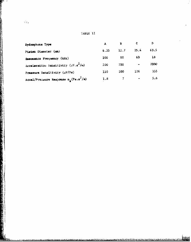
Hydnphouat ype AAL C D
Pis Di ar (a) 6.35 12.7 25.4 63.5
zsnenCA 'Frequency (k~lz) 100 80601Fmas~u- Saaitivity (OiPs) .110 100 126 355
Ao~/r-sr apni ma(Pa.a2/a) 1.8 7 - 5.6
AoI/r_•r

UNCLASSIFIED UNLIMITED FIGS. 1,2 &3
S(a) (b)
FIGS. i(a)&(b).IDEAL HYDROPHONE IMPEDANCE
FIGS. 2c)&(b). HYD!ROPHONE WITH ADDED LOSS
tCm Lm
, R
TC m
F.C3. 3. H ROPH 0NE EO JIVALENT CIRCUIT
-UNC' ASS',FiEE) UNLIMITEDS•• •• . . ,,• .• . . .. . • . . . . . . . • .. . . . . . • . . ...__- .. -

r
i
$TATE C)II,
'i --
"
Fc -5, 0 mr
"rcV0. !
c I, , 0
'F
I ? 0--
-+
ui . L
SC ,
•, Fc = O , 2",.-. -(C ., 0..
-- 0:z
- -J-
*y
- ;
. A
:•.t"°,.

ALL CUPVES F.P IES2NAN-F -E -ENCY F, 100kHZ
A~½FF K
I
I-G !c LPC"_:IViL=o, T. F F ,C IE NCY
'-Fc
S~~~~FIG 4(o". £Ct:,','_, ENTr "ThFPMAL "N-"i"-: PP"-SSUEF- OP.
4- t-HYDROPHONE WITH PV:ALLEL Z-'EbSISOP
U'IC•.SSIFED :.L..ITED

UNOL
;FEn SEA A.C~ E 0 , 0
kC
c• 30
F- i! FN - .Y
H0 2Cr-0
u.
t S
FI-- 5- --" - -
/ " l[ - % :
_- :.-
'FaCr F,.%$C- -
in.
I --
H Y Dl) R.C P H O 4
, U N C

~~~~~UNCLA½:F'f'r?) U_. NY"M.,IATED.,pG4b
A _ 2:....ES 'FOR -. 0 i , -•, =
t/
-,-/
I,,
C -,, -i';L .'

UNCLA F•, ,FD UNLIMITED F;-, 5(o)
t
THERMAL NOISE IS LESS THAN AMBiENT NOISE
I:R 7; GS -A r CD WHEN HI -F> 2 F, ,
F k
F,F'7
4
;I F-VE© ,C k Z
,.nF IG . 5 ,ýa , V A L U E S O F F 2-• VS
-. E.A
.. 0- UNLASSIFIEDK UNLIMITEDL

4 -0 4
-t
tt! ic
14 .
0 4x04
I, j+
+ //
4.i /4-
4/ t-t t I
"/ t.9.
/ ±
' 4-
- /-I
1- ±
.0 {

UNCLA$SIFIED UNLIMITED FIG 5(b)
USE SCALES A & B AS ;ND!CATED BY
DASHED L.:", " -N ON SCALE C
T ý,T;EN D•A•A v;t J FPCM THUS VAL-E THROUGH
kt CtICSLN ýA-ýLE -PF, P7, ON SCALE D T'O
"O -•-,OO DETERM.NE 3," QF Fc F, ON SCALE E
! L06C C)4 ~L C
B.
-4
S. Cl. b) NO ,M OG PAMV FO0P C AL C ULAT 10N 0OF -- F. F,
LU N C L A S S IF :i E D ' I M T ( D
U.' Iu;E

-*1oz
z
Li
4-0
>
-J
!00
Ln-
I C - • -
OCC
k 0 .
S- :Q-
0 W
L ... .. . *0. _' -
F; D
-o- - -- . - -----.•---- ---- ~-

-..,: - .. .
-- -.=..
*,c-- -=- 2 -
--- - -7
071
t- • - = -O1
NOW-
Ar0
F = 00
, 6c Q© UI'VA, Ez- •i .... ,,• SE-,o: ,• • •
o =•
SSF1F- D L: TEC

Tr-4E PMAL N0'S E
SPECTRUM, LEVEL
!N iHz EAND
20-
ioI- A
- z Z:0
QnQ0
r S0
0 =0

UNLA.2LED i'2 tE ""FIG 6(b)
5 -
/
tt
//t"A
-S.,
S:: " • '- "t'",'• " •'-'. ;td :• ,• L ,,r',.c,• ?" . IA•! " ",''@ ': -r• I b:.,., _.,-,,- , - -- " ... u .1 t O b

UNCLASSIFIED U, ME D FiG 7.
THE.MAL NOISE IS LESS THAN
A M8!E t4 T NOl ! SE (FORP OSS 0)
WHEN 0 F > Om __ Ff
,kL
I ~ I{
F
1J-
iy
I (I
7 iC7- VA LCI U" -1 0 FVS
U NIC L A S Sl E U 4~ UAI TE,-

UNCLASSIF! ED UNLIMITED F'IG.S
I
• •/• p~ . "fp
ApS,, , . - ' X .
-. , ,. . .,-., ,.-CERAMIC
I'., ,,,, . "STACK
- 7 7 ' .1 '- //
V KSK,, ~\\
Fi$.3 DIAGRAM OF PiSTON-TYPE HYDROPHONE
UNC•'LASSFIED U N LIT IED

UNCLASiFIED UNL_ HAIT E D F G 9.
CL
I0
E FLOA "4 '- )1 ,1 ' D
FO YI(~OE

IN
fI
C ii
i -,.. -.,
0
z
. .. . . . .. . . . .t . . . I ._ ._ . _ L i ' + . " ; ..ICE
L>' :E NCY
Fl
11o)

UNCLASSIF; 'EU L!;JMITED F!G GO.
I." H~vti . 00k !O •HZK 2) 2 mm P 2 S N, 1 j
I
NOSi.E N
N C iO pF
-- 4.
Fl-A NOISE)
S- L ;LN'. " -
FIG 10 AM-RLIF:IER & Ti-FR• ,,AAL OSE v F-REQUENCY
",FOR THEE,,y.,, riONLi DESIGNS,_
UNCLASS•FIE.D •;1kJI Mi TL•:D

UNCLASSiFIED UNLIMITED FG.I I .
2 inIt It Ii
1-
I K-
'1,
rI--
i
0.... .. A. .i.. A i iL~too
F! 11 ',- E n•, , t D P
I0 R S P E I , -OH0-10 -1 N~UNi'i~E UNAIE

UNCLASSIFIED UNLIMITED F I 12.
'Z,
m 3 jx 3
> F,
IK
'J ;7 K: 2
S2F 2
i
'i'
- m FiG. 12. MECHANCAL REPRESENTATION OF
H Y D-O-it ELEMDN T
-i -
UNOLASsIHCED UNLIMITED

UHCLAZII. UNLIMITED I G. 3.
r-
r"
k!3 k23 300
r Na; :=15
iQo
f AND r p..
L. / -I
OUTPUT
6rlx /X
Ltlxo
6 C)x 1 2
FIG IO
II
I-- II
-- = ' 1 1 1 t
S- 3. -. - -I
o--4 6 03•O
• tn FtG ~. 1. CCELE2AT ION R[SPO N'SE OF HYDROP:-HONF_S,.EFFE-,,OFCACELLNG FO? ,~M!NALLL BALAtNC',,'r:E ligY*-Q'.• ELE.,,LNT
•-• t-'- [NCi AYSiPIFF)D ULIM4IITED

•" "''-FE IIMITLD FIG 14.
0' r,
!- I
7- ~ ~~ E F F E- Ff; I! - i .
/ f
I - Nv - '-0
L'qlx,, 1t\ ;
--,I 1 I1
U • i i

.~UNCLASSIFIED UNLIMITED IG. 15,"-
'I 4
I -
' I3 1
c ' I
,C. /
,,. 1
,I \
u 0 - A"
.> FO ALL.
'- a''- : J ''
4 . .'.9 -.- '.2--: "-c,-SL ... . .. . 32" 'z .-.- , :
a; a- "+ n n +_ _ - -- g .•., .- : . • © ,a• . 4 .. . .k: ' 2
---- 0 i,4 -. '0
-N, -- E--E
,.G. ,.,,ACCE .?ATiO-N RESPONSES~EFFEC- OF Uh,3A.LANC.& FO? HIGH - Qm ELEMENT
4' U--kNCL4..,,LED UNLIMITED

'JNCLASSIFIED UNLIMITED FIG. 16.
-
: z FOP, ALLN ,
4-
<B
LU
. .... .C 0 , S5 S -- x CO " k 2 3 00.C N 2 i 1-
< C %BALANC-EC, ST:FT ESSk 3•,• k2ý=240.) N2;
1 0" -
a
z
Ff ~ ~ ~ ~ ~ 5 GFOAC TICN R ALLC--'
i--J
E F FE C UF .. J,3i ,A.t•.S- F- R L-OW 3?m 1 L k .'EM N T
N ~UNCLASSiFIED UNLIMITED

SUNC AS !F D ".. ..... ED F..IG 7
:• O<
a: -
ww
00
1 w
_t
I0
d S2 j
U A F UN LIMITEJ (J)
---" 0.Id'
t-- -
N ='
IIOc [~Ul% 3'd
S0 © -
S 2-
• UNCLASSIFIED UNLIMITED

U NCL AS SF I E U NL.I M ITED FG. I
0
CL
0:
1w
Uj
LUJIFI3 ~ ~ ~ g U'lSI
U N A. F 1L D L K T E

11'-H 1"U•.•r' F •'. ,F ED •NLi .. I Eli:I I
~-I
i
'.1
o_
'9 AC- C, ,/,E L A : P----- PI- Rc PO
N-- CN
-!_-i-
"14 It
ii\C' \-
2;9ACLP1O'iPE2UF %OS
/ ~ ~ ~ N L 5 F E U HL. . .. . . .... . ..... .. ... . . ......- .. .. .... • .. ...

I
*1ic ) - -- • -- **--
.- 1
-0-• i
-,J £UFE iq
• i ('9

FIG.-T 20.
AND ' I Y°-
/7u
4
/l
.. _.• .... _J• £ • . .. ... _ ; _ _L/• ! .
-i--

~CL
hiijkj
of

-430
0
I
10 100
FIG 21. VALUES OF ml = CUN
UNCLASSFIED UNiMIE

WIN",.
NN
40
I T
:1 ,P~EPCAZ :-R-CPHCNE

S'.- .L .: U* , w •. • "arr . ,rIG" 22
• R!CA • ":. qi'- r C -Ei ,,
S.. .. .1z
7..
XTOTAz- X0:SL
P~ 7(flJ DY 40P N
SFiG 22 AMPLIFIE:-R THERMAL NOISE BACKGROUND
S~UNCLASSIFIED U"L,'iL..I~iED ,

DOCUMENT CONTROL SHEET
UNCLASSIK}fEDV-t.al l -curity classification of sheet ...............................................................
(A, tsir .A possible this sheet should contain only uncla•stiAd information. If is is necessary to enter3jssit~isJ information, the box concerned must be marked to indicate the classification eg (R),(C) .r (S)).
1. DRIC Reference (if known) 2. Originator's Refer. c r 3. Agency Reference i4. Report Security
ATTWE Tech lbotp 52177, ClassificationAc:'1. 1(. 39008
r. 'rlglnator's Code 6. Originator (Corporate Author) Name and Loc~ation
(it known) Admiralty Underwater Weapons Establishment
0125u0 Portland, Dorset, UK
14.'fpvnsoring Agency's 6s.Sponaoring Agency (Contract Authority) Name and LocationCode (if known)
7. Title !L),L::( ir: iT17)ad-'tnd Hydrophones
le.Ticle in Foreign Language (in the case of translations)
7b.Presented at (for conference papers).Title, place and date of conference
8. Author 1.Surname, initials 9a.Author 2 9b.Authors 3, 4... 10. Date. pp. ref.
tan -field D. 5/75 59 7
11. Contract Number 12. Period 13. Project 14. Other References
1'. Distribution statement
UNLIMITED
15. Descriptors (or keywords'
The sources of noise in underwater electro-acoustic hydrophones
are considered with particular reference to piczoelectric piston-typeelements. Expressions are derived for the various contributions, andtheir influence on hydrophone design for broad-band reception isdiscussed.

.0 ~02+ -V
co0 ~0
4)~OG $3 .
- k M 4- 0 U) - 0o. (N ) r4 ;( E I P 4 So
4) 4) £.~Wo0. P. \0 0
4- 4-~ 0C)0 (Ud
m -0.4.
ox i- u-~ ,40)S 4200)H (.0 M- m~(0 l-
4 *.-4 o (L) 0 4)
$4 0~
-' 4 4- -4ý 0 0 0
'-d 004.0 0 -,4 004o. F 2 .4 V.U o Co P.
..4 1* i :,- 4 0 *.*43 ( 4 , T
.A 0 U k O
0U V, k4 (.2 0 ILI E- ' 0 4~ o 02E - ~ to00) 0 ~ El-C 00 0
4p 0Id'C E-s -i0. ) 4) ( 0 - CU E-4 C4w D) m0
oo .> 0 .2o>
4) .d4)
0 re)U .*'-Kr *o 4) NrC- 00 -- P- 0
0 ';4 0 'ol 0o *I)- O p2 .- .. *4U *.4c:- r(nJ 0 00 0 P.
4 ) L 4) 00 0. 4) r.- .
0) 02 ON 4 0 Q) N 4 700)
0 "4q( '( 0 rl.)'(
024 0. t. EOx~ 0.4
f4 m .0 0..4
4-1 *'- 9~ *j6to t- 44)C
H2 4. 2 (..C) w02 0~ 0 )04
to 0 0 0 o..o41
o
E-4 o 0. +. 0 -4 1c2 W 08192 0 OwkO
I-4 to$ 0 2 0 'd E* 4 '.- 2 . 0 2
E-4 -Hm ) 1 2 , E-4 4 0 .44 0 COtl-- t 4 000 0 : LI- W 020W 0~
.0 r4'. I Z 4CY., 9.0 P-4 .,
0. ) (U.D0 0.( 0. ".w