Embed Size (px)
Citation preview
INSTALLATION, PROGRAMMlNG AND MAINTENANCE MANUAL
J !o-----~) J
~~ ______________________________ ,, ____ w"--u.
~ .................................. _C ~ U L
:r l <: ~ ~

SECTION 1
2
3
4
5
6
7
8
9
10
11
12
13
14
15
16
17
18
19
20
21
22
23
24
25
26
27
28
29
30
31
32
33
34
CONTROL SYSTEMS ................................................. TECHNICAL SPECIFICATIONS AND STANDARD EQUIPMENT ................. INSTALLATION .................................................... QUICK CHANGE TOOLPOST ........................................... TAILSTOCK ....................................................... MAINTENANCE ..................................................... MACHINE AXIS FORMAT .............................................
PAGE
1
3
6
11
13
14
15
MAt\IU~ JOO rvt)OOS •••••••••••••••••••••••••••••••••••••••••••••••• 16
KEYOOARD
AXIS . POWER AND EMERGENCY STOP ................................... CYCLE MJDE AND OPERATION ........................................ MAt\IUAL JOO CONTROL .............................................. FUNCTION SECTION ................................................ MJDE SECTION .................................................... NUMERICAL KEYS ................................................... LIST OF M AND G CDDES ........................................... STARTING THE MACHINE ............................................ MJVEMENTS AND ASSOCIATED FEED INPUT ............................. CIRCULAR INTERPOLATION .......................................... G55 MACHINE OFFSET ••••••••••••••••••••••••••••••••••••••••••••••
FLOAT DATUM ..................................................... TOOL LENGTH OFFSETS ............................................. EDITING TOOL LENGTH OFFSET ...................................... SPINDLE AND COOLANT CONTROL ..................................... p~
ABSOLUTE/INCREMENTAL ••••••••••••••••••••••••••••••••••••••••••••
ENTERING A NEW PROGRAM ••••••••••••••••••••••••••••••••••••••••••
REPEAT FUNCTION
OFFSET FUNCTION
.................................................
................................................. .AlJXILIA.RY' FUNCTIONS •••••••••••••••••••••••••••••••••••••••••••••
INPUT FACILITIES ••••••••••••••••••••••••••••••••••••••••••••••••
DWELL FtJNcrroN ••••••••••••••••••••••••••••••••••••••••••••••••••
EDIT FACILITY •••••••••••••••••••••••••••••••••••••••••••••••••••
CASSE'ITE OPERATIONS •••••••••••••••••••••••••••••••••••••••••••••
DATA LINK FACILI'IT ••••••••••••••••••••••••••••••••••••••••••••••
EXAMPLES ••••••••••••••••••••••••••••••••••••••••••••••••••••••••
18
22
23
25
28
31
33
34
39
41
43
46
47
48
50
51
53
54
55
56
60
61
62
63
64
66
69
80

Easiturn utilizes the latest advances in microprocessor
technology. These advances can be combined with a full
backup facility, extra equifffient, indexing tooling
systems, and work holding accessories to provide a
powerful and very versatile machine tool.
Other important features of Easiturn include canputer
software which enables the simulated running of
programs for error detection, which can save valuable
pnxiuction time. Inputs an::l outputs can be m::mitored
to enable Easiturn to work with robots in a flexible
manufacturing system. The RS232 link allows DNC
operation to be a stan::lard feature of the machine, thus
allowing direct programming from a host canputer.
CAD/CAM systems utilize this function to the full.
Easiturn is fitted with a parallel printer port, to
offer the user full or part program hard copy
printouts.
Easiturn's programming format is to the International
Standard incorporating G an::l JV1 ccx1es. Alternatively
function keys can be used in their place to ease
programming. These functions keys offer a simple
machine shop language so programming can be
accanpl ished successfull y by operators having no CNC
experience of G or M ccx1e format.
Error messages are built into the system to help the
operator to drastically reduce the amount of erroneous
data being programmed.
As with any CNC machine tool, the programmer an::l
operator should have a gcxx1 knCMledge of machine shop
practice and be familiar with nEchine shop terminology.
The quality of components produced is only a reflection
on the programmer.

SECTIOO 1
THE <NC amIDL· UNiT
PNC 3 DESCRIPTION
The PNC 3 is an extremely versatile continuous path, computer based
programmable numerical control unit designed to control up to 4 axis of
movement where precise control and positioning is required. Related processes
and functions can also be controlled by the PNC 3. The programming of stepper
motor ItDvements and the process control element is explained fully in this
manual. The PNC 3 we are confident will be found to be very easy to operate.
From the front panel total control is obtained by the following features:
An easy to use keyboard for the input of data and commands by the a) ISO G and
M code programming b) keyword system.
The 9" Display provides the user with:-
1. A display of the complete machine status
2. Prompts to assist the user in using the control system
3. Sections of the program during program loading, editing and execution
4. Machine, Control Unit and program error information
Integral control unit memory stores typically 500 blocks.
Programming facilities include, repeat loops, threading, fixed/floating datums,
dwells, program offsets, inch/metric and absolute/incremental programming with
any mix.
The integral fast magnetic tape system provides unlimited program storage
space, with each cassette side storing up to 3000 program blocks per side of
tape.
Keyswitch to give manual programming/control, or single step program execution
or automatic program operation. program START and STOP switches.
Jog system giving manual control in all axes with plus and minus keys for
feedrate override control.
Integral high power stepper motor drives.
1

CNC CONTROL SYSTEM SPECIFICATION
1. 490x290x335 rnm Self Contained Console.
2. Green on Black 9" VDU with Anti-glare screen and outlet to external 1V
Monitor.
3. Alpha numeric keyboard allowing full manual Data Input.
4. Mini Magnetic Cassette unit for Multi Program Storage.
5. MDI Single Step and Auto Selector for programs.
6. RS232C Interface 7 Din Pin connection to computers and paper tape punch
units.
7. Parallel Printer Interface for obtaining hard copy of programs.
8. ISO Format - allowing 'G' and 'M' Code programming from DIN 66025 extract.
9. Full 'G' and 'M' Code Listings on VDU when required to assist programming.
10. Single Mode Selection Keys.
11. Axis Jog on All Axes with variable feedrate and 0.01 rnm step.
12. Feedrate override from 1 mrn/rnin to 750 mrn/rnin.
13. Programmable Spindle Speed 0-2000 RPM.
Programmable Feedrate 0-1500 rnm/rnin.
14. Linear Interpolation on 2 axes with vectorially correcting feedrates.
15. Circular Interpolation on x-z plane.
16. Absolute/Incremental, Inch/rom programming throughout program build-up.
17. Manual and programmable Program stops.
18. Repeat facility allowing build-up of canned cycles for screw cutting.
19. Floating Datum Facility.
20. 500 Block Memory (1000 blocks available).
21. Tool length Offsets for up to 16 tools.
22. Programmable Coolant.
23. Programmable Dwell from 0.1 to 9999.99 seconds.
24. Four Auxiliary Outputs.
25. Six Programmable Inputs.
26. Optional 3rd axis control.
27. System resolution 0.01 rnm (0.0004").
2

TEnlNlCAL SPECIFlCATICliS
SWING OVER BED
SWING OVER CROSS-SLIDE
SPINDLE BAR CAPACITY
DISTANCE BETWEEN CENTRES
LONGITUDINAL TRAVEL (Z)
CROSS TRAVEL (X)
280 MM
170 MM
26 MM DIA
500 MM
480 MM
175 MM
SPINDLE SPEEDS - VARIABLE 0-2000 RPM
SPINDLE DRIVE
1.5 KW (2 HP) AC 1420 RPM 6.7 AMPS
AXES DRIVE MJ10RS
HIGH POWER STEPPER MJ10RS
X AXIS STEPPER MJ10R - 200 STEPS/REV
Z AXIS STEPPER l~1OR - 200 STEPS/REV
FEED RATES - RAPID TRAVERSE ON X AND Z AXES GOO=1500 MM/MIN
(60 INS/MIN) FEED RATES INFlNATELY VARIABLE ON X AND Z
AXES
0-1500 MM/MIN (0-60 IN/MIN)
MECHANICAL RESOLUTION - 0.01 MM (0.0004 11)
LINEAR INTERPOLATION - ON X AND Z AXIS WITH VEC'IORIALLY o)RRECTED FEED
RATES
CIRCULAR INTERPOLATION - ON X AND Z PLANES
FIXED ZERO REFERENCE POSITION
LOOKING AT THE FRONT OF THE MACHINE
Z=ZERO mEN THE SADDLE IS UP 10 THE CHUCK
X=ZERO mEN THE SADDLE IS AT ITS MAXIMUM DISTANCE FROM THE FRONT OF
THE MACHINE
3

l'1ACHINE DIMENSIONS
LENGTH - 1370 MlvJ.
WIlJI'H - 610 MM
HEIGHT - 1680 1~vJ.
WEIGHT - 600 KG
TOOL LENGTH OFFSETS
TOOL SHANK
(54")
(24")
(66")
(1320 LBS)
- 16 TOOLS
- 16 MM SQ
4

5" 3 JAW CHUCK INT. 7 EXT. JAWS
MULTIFIX TOOLPOST
MULTIFIX TOOLHOLDER
GREASE GUN
HARD CENTRE NO.3 M.T.
SOFT CENTRE NO.4 M.T.
'IOOLPOST KEY
2 - 1 AMP 20 MM FUSE
3 - 15 AMP 20 MM FUSE
CAMLOCK KEY
1 TOOL rox lOlL CAN
2 SCREW DRNERS
4 ALLEN KEYS 3, 4, 5 AND 6
4 SPANNERS, 12/13, 14/15, 16/17 AND 19 RING
1 MINI CASSETTE
1 POT OF PAINT
Flood 000lant System
Tool Kit
Halogen Lo Vo Light
Operation and Instruction Manual
Automatic Lubrication System
EXTRA EQUIPMENT
Spray Mist Coolant
Pneumatic Chuck
Eight Station Indexing Tool Post
Printer
CAD/CAM Systems
BBC Apple and IBM Software for Off Line Programming
Desk Top Programmer
Rooot
SAFETY FEATURES
Axis Llinit Switches
Diagnostic Fault Finder
Key Operated program Control
Interlocking Chuck Guards
5

sEctioo 3 INSTALIATIW
LIFTING MACHINE
The lathe will be supplied with four lifting hooks (BVS.160/80). To fit the
lifting hooks to corner of the cabinet, first remove the eight plugs, two at
each corner. The hooks are secured by MlO bolts - 30 long. Bolts ard. washers
provided.
.. 350 KG
DO UFTING HOOKS
;1
o o
~ACKING PADS
Check to ensure that the lifting sling is of correct capacity to lift the
weight of the machine ard. that the sling is in good condition.
It is cdvisable at this stage to fit the jacking pads - see section on
levelling.
6

fOUNUATIOI.'J
The lathe should be positioned on a firm level base, preferably concrete.
1500
See installation DRG. 'SK.726.A'.
LEVELLING
Four jacking pads must be fitted at each corner of the cabinet. Bosses are
welded into the cabinet base for this purpose.
LOCKNUT'S' MI2
Thoroughly clean the bedways and, using a precision machine level at both ends
of the bed, level the machine using the jacking pads thus:-
With locknut 'B' slack, rotate screw 'A' until the bedway is level. Tighten
locknuts 'B'.
CLEANING
On delivery the machine will have the bright surfaces coated with a protective
solution. This must be removed using a kerosene base solvent before any
attempt is made to move the slides or operate the machine.
7

EI£CT1UCAL SUPPLY CONNEL'TIOI.\1
The regular electrical mains power supply to the machine is 3 phase + N
3dO/440V 50HZ or 1 phase 220/240V, 50HZ.
Connect the mains supply to the isolator box located at the rear left of the
machine.
vaLOW / GREEN EARTH
BLUE
'-'-~r-- 3 BROW N
®CD9 <D09ClD
3 PHASE & N
BLUE
BROWN YELLOW/GREEN --tt--==-~ EARTH
I PHASE
N.B.
only a competent electrical engineer should commission the machine.
8

LUBRICATIOI.'J
Lubrication to the bedways, saddle, cross slide and ball screw is supplied by
the automatic lubrication system.
Ensure that the reservoir on the system is full.
, .~
LUBRICATION
SHELL CASTROL
cif VITREA 68 PERFECTO NN
rat VITREA 68 PERFECTO NN
/ ALVANIA N93 SPHEEROL AP3 . .J
All slideways should be lightly oiled before rrovement of the saddle am
tailstock.

CHUCK AND FACEPLATE MOUNTING
Before mounting chuck or faceplate first ensure that the spindle taper and the
internal taper of the chuck or faceplate is clean and free from dirt or
protective covering.
The line on the camlock cams in the spindle should be in line with the mark on
the spindle old when the chuck is loaded to the spindle. Load the chuck and
turn the cams with the key provided in a clockwise direction to tighten and
lock the chuck to the spirxile nose. The correct position of the cams in the
lock position is shown in diagram 2 - Fig.4.
It may be necessary on chucks supplied without the camlock sttds fitted, to
adjust the sttds so that the required cam action is obtained. This can best be
set by screwing the studs to the bottom thread and then removing one complete
turn. Adjustment for locking should then be carried out.
<D
®
FIG 4.
CAMS IN RELEASE POSITIO N.
~MS IN LOCKING
POSITION.
r
-
\..
®~ r--- -!- ::::J
~ -~ "--
~
-TO ADJUST·CAMLOCK STUDS: REMOVE LOCKSCREW ® TURN STUD ® ONE FULL TURN,IN OR OUT AS REQUIRED. REPLACE LOCKSCREW AND TIGHTEN.
NOTE :-A DATUM RING © ON EACH STUD DENOTES THE ORIGINAL SETTING.
10

Sa:rICN 4
To change tools in the toolpost either pull or push the clamping lever to the
central fX)sition ard lift out the tool holder. Insert the new tool holder
ensuring the height adJusting screw is firmly down on the base body, ard clamp
the holder by either pulling or pushing the clamping lever to the locked
position.
To set the centre height of the lathe tool slacken off the clamping hardle, ard
loosen the locking nut - then either screw the height adjusting screw clockwise
to raise the tool holder or vise-versa. The manufacturers repeatable accuracy
on clamping is 0.01 ITUU.
11
I-' N
METRICMM. GRADUATIONS ENGLISH INCHES.
~n:r~II"~lnll!"~in~!f~:'lrl~llInll~I'IIIJI~1l ~~ I 1"111 , 'I' I: I'" 1"'1 ' III' ~ I '11)'11111111 I ~II
.. /
/ /
// / /
/ /
ADJUS T BY FACING HANDLE •
FIG 5
TAILSTOCK ADJUSTMENT. ;; g i

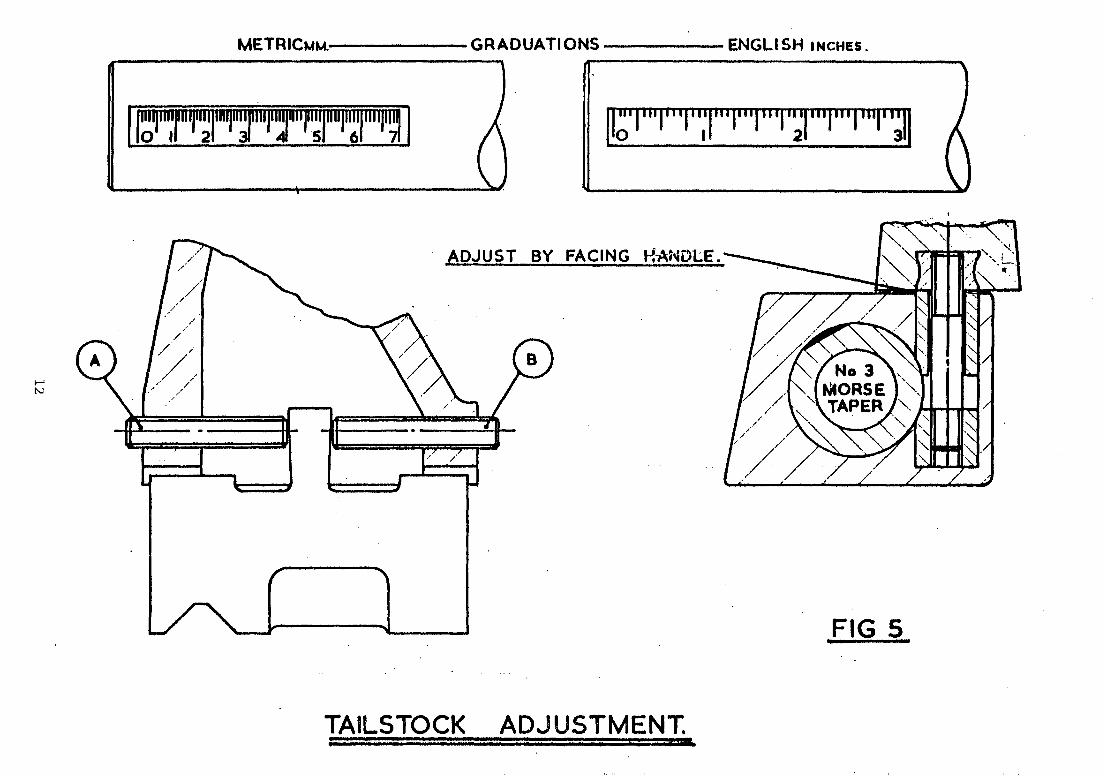
The tailstock is of sol id cast iron construction IIDunted on a cast iron shoe
for adjustment and the turning of shallow tapers.
The tailstock quill is self ejecting and is graduated for direct reading for
drill depths etc. The quill has a 3MT bore and may be locked in position by
the locking handle as shown in Fig.5.
LOCKING
The tailstock is locked to the bed by means of a bed clamp operated by lever
(B) Fig.8. The quill is locked by IIDving lever (A) away from the headstock in
a clockwise direction.
AWUS1MENT
The tailstock is set to turn parallel to the bed. Should any cdjustment be
required i.e. taper turning - adjustment is made by the two grub screws at the
front and back of the tailstock. To adjust, loosen off one of the grub screws
A and B and tighten the other until the desired taper is achieved. Fig.5.
NB. Ensure that the two screws are tight before reclamping the tailstock to
the bed. The amount of set over required for a given taper may be
calculated as follows:-
Set over required (rnm)
Set over required (inches)
= Length (rnm) x taper (rnm)
2
= Taper per foot on dia. x length (ins)
24
13

SECI'IOO 6
Routine inspection and maintenance of the machine should be carried out to the
following schedule:-
PERIOD
DAILY
WEEKLY
SIX M)NTHLY
ANNUALLY
MAINTENANCE REQUIRED
Check oil level in reservoir.
Clean out swarf.
Clean machine thoroughly.
Check coolant tank.
Check adjustment of saddle strips.
Check adjustment of cross slide strip.
Grease headstock bearings.
Lubricate tailstock barrel.
Check machine alignments and accuracy.
Check headstock bearing adjustment.
Check spindle drive belt.
HEADSTOCK BEARING ADJUSTMENT
Remove the green rubber mat above the headstock, then the inspection cover
which lies beneath.
Slacken the locking grub screw, adjust the pre-load on the bearings with the
locknut.
Note the thread is left hand.
After tightening of the locknut check that the pre-load is not excessive.
The machine should run at top speed and the bearings should not exceed 65 0
(l50"F) •
NarE: A certain amount of temperature rise must be expected when running the
lathe at high speed but it should be possible to place the hand on the
spindle nose after an hour's running without discomfort.
Check that locknut is tight up against bearings after adjustment, and
re-tighten the grub screw.
14

SECl'IOO 7
MAOIINE AXIS FORMAT
Fig.S illustrates the plan view. The Z axis runs along the length of the bed
and the X axis along the cross slide at 90° to the bed. The plus and minus
signs indicate the direction of the tool.
Fig .SA ABSOLUTE
Fig.SB INCREMENTAL
FIG. SA
-~
1---
l--
...
FIG.SB
(Z axis) To the left hand side of ZO towards the chuck is
negative.
To the right hand side of zO away from the chuck
is positive.
(X axis) Xo is on the centre line of the spindle. Away
from Xo towards the splash guard the movement is
negative and towards the operator fran Xo is
positive.
(Z axis) Towards the chuck is negative.
Away from the chuck is positive.
(X axis) Away from the operator is negative.
Towards the operator is positive.
x-' x __________ JJ __ . <rdJ...-__ )(a
z--s
-----.-----<rd~ ~ ____ _
15

sEctioo's
For operating Easiturn in the manual rnxie, that is without the use of
programming, first set the key to "MAN" position., The machine can be jogged
into positon by depressing the directional arrow keys in the jog button
cluster. One press represents 0.005 rnrn or 0.0002" jog. If a jog key is held
depressed, continuous movement is maintained. Depress the appropriate arrowed
key first which will select the slowest jog speed arrl then at the same time
depress the + key which will accelerate the jog speed. Continually holding
down the + key will accelerate the jog speed up to its maximLnn value
23<:1 mm/min. the - key allows the jog speed to be decreased.
Movement will only occur as long as the appropriate arrowed key is depressed.
Caution should be taken when approaching an obstruction, such 'as the chuck or
the workpiece. Because the machine needs a short distance to decelerate.
MANUAL
! t +
• ~
-
The directional arrow keys represents the movement of the tool. If you want
the tool to move to the left parallel to the Z axi's (Z plus), then depress the
button with the left horizontal arrow. Similarly to move the X axis then the
appropriate vertical arrow key is selected.
16

Any attempt to jog to a position outside the machine parameters the control
will automatically reduce the jog speed into creep feed, before the overtravel
1 imi t is encountered. Then the screen will respooo wi th "MOVE EXCEED MACHINE
LIMIT" • Depressing the reset key will clear the screen which respooos with
"PRESS ZERO TO DATUM THE MACHINE". Depress the zero key ard datum procedure
will commence. Normal operation is restored.
17

18

NXi -:!I ~ iilll~~~~~j ,I '=
if 0 - ~ " 1 11 · IV til CD i" IJ I 1 W 0-1.0 ~
Itl
FRONT VIEW OF CNC cONTROL UNIT
"_ ...
rr-=-================~ll
/ I I! Ii; I' \I
I II
I ,! !
, I q:
Iii: . '
I ~
i 'j 11
'-- -o I :
! I
I.====:======::!J I
~ 19

REAR VIEW CNC CONTROL UNIT
CONTROL UNIT O~/OFF
~ 2~ 3 V 2
P R I
~
F I
FAN AIR FILTER
otti=o VIDEO EXT
@
CONTROL UNIT MAIN FUSE
20

AXIS POWER ~ EMERGENCY STOP
"'-
~ -- -- .... ~.:. : .. :-.-:.-:-~ .... ",:",
I \:
l?ROGRAM STAR.T ISTOP
\1 , ,~==,.;,--.-: --
@ -D ............. -~:
---
- -. -
EJ -t::f CooQ~''''''''''''
-_.
@i]i~JSiijJ\~~' III -- -- .. --- --- -- '" il ((;~~
- ... ';_ .... - -~.- .:-::--:"-'- :.-~.- ~. n ... -: •• _ .. ;~- -_. - ..
:lr'c;o, [8~IR~cR~TI JOi ~~ It-r'';;"GX
\
Ta~ ~~~ r- ~ ..
~g" i I! - I i=fDlt" S. 2 456
I@i ~,!!!!>I (1-=,::''-' . I 231U I"IIM '..-.0; 0·-I~ I. .:::::J ! \ - ...... I - c_ ;;;r, ~ I-
I .... .. -- .. -.~ ~~ ......... -... .. __ .. _._ .
MtNUAL .JOG BUTTONS
21

KEY
o
D
o
D
FUNCTlON
CONTROL PavER LED.
AXIS POWER BUTION. THIS BUTTON ENERGIZES DRIVE MOTORS. SPINDLE DRIVE MOTOR.
EMERGENCY STOP
EACH TIME EMERGENCY STOP IS USED IT WILL KILL POWER TO
ALL DRIVE MOTORS.
THE MEMORY IS Nor AFFECTED. POWER IS TURNED BACK 00 BY UNLOCKING EMERGENCY STOP AND DEPRESSING THE AXIS POWER
BUTTON.
22

SECTIOO 10
KEY
STOP
START
II II
STOP
START
II If
SINGLE STEP
AUTO
~::::::I PROGRAMME
FUNCTION
DEPRESSING THE STOP BUTroN WILL HALT THE AXIS l"DVEMENT IN THE CURRENT BLOCK. WHIIST IN AUTO OR SINGLE STOP EXECUTION CAN BE RESTARI'ED USING THE START BUTroN. DEPRESSING THE STOP BUTroN WILL KILL ANY MDI MOVE AND CLEAR THE BLOCK.
PRCGRAM START BUTION WILL EXECUTE THE CURRENT PRCGRAM IN MEMJRY OR EXECUTE THE NEXT BLOCK IN SINGLE STEP l"DDE.
THREE POSITION KEY SWITCH
MAN POSITION - SELECT MANUAL ALLOWS THE USER 10 ENTER NEW mTA, FOR MDI MOVES, ENTERING PROGRAMS, EDITING, CASSEITE ENTRIES AND DATA LINK. IN THIS l"DDE THE USER CAN r-DVE ANY AXIS OR OOTH SIMULTANEOUSLY, DEPENDING ON REQUIREMENTS. STATING CO-ORDlNATES FROM MACHINE FIXED mTUM, FLOATING mTUM AND MACHINE OFFSETS DO NOT AFFECT MDI MOVES.
Continued •••••••• 23

SINGLE STEP
MAN@A~
SINGLE STEP
ALLCJtJS THE PROORAM IN MEMORY TO BE EXECUTED CNE BLOCK AT A TIME. IN SINGLE STEP MODE, WITH THE DEPRESSION OF THE START BUTTON, THE MACHINE WILL EXECUTE ONE BLOCK OF INFORMATION ONLY AND STOP. IN ORDER TO EXECUTE THE NEXT BLOCK THE START BUTTON WILL ONCE AGAIN HAVE TO 'BE DEPRESSED.
AUTO
WHEN THE START BUTTON IS DEPRESSED, THE MACHINE WILL EXECUTE EACH BLOCK OF THE PROGRAM UNTIL EITHER THE END OF THE PROGRAM, PROORAIYl STOP, OR A TOOLCHANGE IS REACHED. OPERATICN CAN BE CONTINUED BY DEPRESSING THE START BUTTON.
24

SOCTIW 11
KEY
[]
MANUAL J(X; <nnroL
MANUAL
! t +
• ....
-
+
FUNCTION
PRESS THIS KEY TO ~VE THE TCX)L lWIAY FRCM THE CHUCK.
PRESS THIS KEY TO MOVE THE TCX)L TCWA.Rll3 THE CHUCK.
PRESS THIS KEY TO ~VE THE TCX)L lWIAY FRCM THE OPERATOR.
PRESS THIS KEY TO I~OVE THE TOOL TCWARDS THE OPERATOR.
THE + KEY WILL INCREASE MANUAL JCG FEED. HOLD IXWN THE APPROPRIATE ARRCW KEY. THIS WILL SELEcr THE SLCWEST J(X; FEED. AT THE SAME TIME PRESS THE + KEY TO ACCELERATE THE J(X; FEED. COOTINUALLY HOLDING l)()lMII THE + KEY WILL RAMP THE FEED UP TO ITS MAXIMUM.
SUCCESSIVE PRESSES OF THE + KEY WILL GRADUALLY INCREASE AND STORE THE NEW FEED.
Continued ••••••••
25

· KEY
f-;,c~ [±]
B
FUNCTION
ALTERNATIVELY THE + KEY CAN ACT AS FEeD RATE OVERRIDE ~EN RUN IN AUTO. PROGRAMMED FEED RATES WILL BE INCREASED AND Rfl~N EFFECTIVE UNTIL A NEW FEED IS READ IN A SUCCESSIVE BLOCK.
TIlE - KEY WILL DECREASE MANUAL J(X; FEED. OPERATION PROCEDURE AS FOR THE + KEY.
ALTERNATIVELY THE - KEY CAN Acr AS PRCGRAM FEED RATE OVERRIDE REDUCING PROGRAM FEED RATE. EFFEcrIVE UNTIL NEW FEED IS READ.
26

r;:====:=1 SPINDLE t::::===='~
KEY
EJ
EJ
1+ I - FWD REV OFF I
FUNCTION
WILL MANUALLY INCREASE SPINDLE SPEED.
WILL MANUALLY DECREASE SPINDLE SPEED.
SELECTS FORWARD ROTATION OF SPINDLE. WHEN IN PROGRAM LOAD lVlODE, PRESSING FWD KEY WILL SELECT MO 3
-CQVlMAND. VDU WILL PROOPT THE USER TO INPUT AN RPM VALUE.
SELECTS R~VERSE ROTATION OF SPINDLE. WHEN IN PROORAM LOAD MODE, PRESSING REV KEY WILL SELECT AN M04 CQ\1MAND. VDU WILL PRa-wT THE USER TO INPUT AN RPM VALUE.
SELECTS SPINDLE OFF. WHEN IN PROORAM WAD MODE, PRESSING OFF KEY WILL SELECT AN MOS COMMAND. SPINDLE OFF.
FCOOLANT
1 ON I OFF
SELECTS COOLANT ON. WHEN IN PR(x;RALIil WAD MODE, PRESSING THE COOLANT ON KEY WILL SElli'CT M08 COOLANT ON CQ\1MAND.
SELECTS COOLANT OFF.
WHEN IN PROORAM WAD MODE, PRESSING THE COOLANT OFF KEY WILL SELECT M09 COOLANT OFF COMMAND.
27

SEcrIGI·ii
KEY
~ ~
rr======== FUNCTION
RESET ·T M G X
BLOCK ED[T 5 Z SEARCH
DATA AUX FEED ZERO -LINK INPUT
PROG CASS LOAD
EOB ENTER STOP -END
FUNCTION
TO RESET FRClVl THE CURRENT [\DDE OR CANCEL THE MOST RECENT ENTRY.
IF THE CONTROL IS SET TO IVlDI AND THE T KEY IS PRESSED, A TOOL SELECTION MENU WILL APPEAR ON THE SCREEN FOR TOOL SETTING AND EDITING TOOL LENGTH OFFSETS, (SEE SECTION 22). IF THE CONTROL IS IN PROGRAM LOAD IVlODE THE T KEY CAN BE PROGRAMMED AS Tcx)LCHANGE M06 BLOCK. UPON SWITCHING THE CONTROL ON FRCM COW, PRESSING THE T KEY GIVES A SYSTEM TEST DISPLAY CHECKING INPUT SIGNALS AND MACHINE MOUNTED SWITCHES.
IVlISCELLANEOUS FUNCTION, REFERRED TO AS M FUNCTION. BY PRESSING M KEY THEN THE ENTER KEY, A LIST OF M CODES WILL BE DISPI:AYED ON THE SCREEN.
PREPARATORY FUNCTIOl.\lS, REFERRED TO AS G FUNCTIOl.'J, PRESS G KEY THEN THE ENTER KEY. A LIST OF G CODES WILL BE DISPLAYED ON THE SCREEN.
THIS KEY WILL ALLCW THE PROORAM TO BE EXECUTED FRCM A SPECIFIC BLOCK IN THE PROGRAM.
EDIT KEY PERMITS FULL EDITING FACILITIES OF THE PROORAM IN MEMORY. (SEE SEC~ION .31 .)
28

KEY
~ L:J
~ ~
I PROG I STOP
FUNCTION
S KEY GIVES A DIAGNOSTIC CHECK, UPON STARrING FROM COLD BEFORE AXIS POWER IS APPLIED. THE SOF'IWARE VERSION' AND DATE WILL BE DISPlAYED ON THE SCREEN.
X AXIS KEY FOR X AXIS MOVES.
Z AXIS KEY FOR Z AXIS MOVES.
ZERO KEY IS USED TO DATUM THE MACHINE. 'IRIS DRIVES THE MACHINE TO ITS MAXIMUM TRAVEL FOR EACH AXIS, UPON STARTING FRQ'v1 COLD OPEAATION YOO CANNar CONTINUE UNTIL MACHINE IS DA.TUMED •
. SELEcrS A DATA LINK TO EXTERNAL EQUIPMENT, EG, AN EXTERNAL C(l\1!>UTER, TRANSMIT AND RECEIVE PROORAMS OR PRINT PRCGRAMS.
AUXILIARY OUTPUTS. THIS ALLOW3 ANY OF THE FOUR AUXILIARY OUTPUT RELAYS TO BE OPERATED.
AUXILIARY INPUTS. THIS INSTRUCTION ALLOWS THE PRCGRAM TO BE HALTED BETWEEN MACHINING OPERATIONS. THE PRCGRAM WILL ONLY PROCEED BEYCND THIS POINT IF ANY OF THE SIX AUXILIARY INPUTS ARE PROGRAMMED TO RECEIVE AN INPUT SIGNAL.
FEED KEY. USE TO SELECT A FEED RATE TO EXECUTE A MOVEMENT
FEED RATES FROM 0 TO 1500 MM/MIN. ~EED RATES FROM 0 TO 60 IN/MIN.
PROGRAM STOP BUTTON OR FEED HOLD. WHEN WADING A NEW PRCGRAM INTO MEMORY, THE PRCGRAM STOP BUTrON IS USED AS A STOP IN THE PRcx;RAM. MOO. ADDITIONALLY, WfEN EXECUTING A PRCGRAM IN AUlD OR SINGLE STEP, DEPRESSING 'IRE PROGRAM STOP BUTTON WILL HALT 'IRE CYCLE OF THE CURRENT IDRK, OPERATION CAN BE CONTINUED BY PRESSING THE START KEY.
29

KEY
ICA~ I
I LOAD I END
EJ EJ
FUNCTION
CASSETTE KEY
PRESS CASS KEY AND A MENU OF CASSETIE FUNCTIOOS WILL BE LISTED ON THE SCREEN. (SEE SECTIOO 32.)
Pt{QGRAI."l LOAD KEY
TO ENTEN. A Pt{CGRAlV1 INTO MEl'1Ot{Y OR END A PRCGRAM LOADING SEQUENC!:!:.
!:!:ND OF BLOCK KEY
END OF CURRENT LIN!:!: OF INFORMATIOO.
ENTER KEY
INFORMATION IS ACCEPTED INTO MEM)RY AFTER ENTER HAS BEEN PRESSED.
30

SECTICN 13
KEY
~ ~
FLOAT DATUM
IOFFSE~ I
r,==== MODE ===~
. REPEAT CW -CCW
FLOAT DWELL DATUM
OFFSET THREAD
INCH ASS - -MM INC
FUNCTION
REPEAT FACILITY ENABLES SPECIFIED BLOCKS OF A PROGRAM TO BE REPEATED UP TO 99 TIMES WITH SPECIFIED OFFSETS. (ALLOWS NESTING OF UP TO FOUR LEVELS.) (SEE LATER TEXT.)
CIROJIAR INTERPOLATION IS SELECTED USING THIS KEY. PRESS ONCE FOR GU2 CLOCKWISE, PRESS AGAIN FOR G03. AFTER DEFINING THE END POINTS OF THE CIRCUI.AR r-DVE, BY DEPRESSING CW/CCW KEY ALLCW3 THE INPur OF THE CIRCLE CENTRE CO-ORDINATES, XC AND ZC (ARC CENTRE Ot'FSETS) • .
fA H.ofATING Jll\TUM !jLOCK G99 WILL CAUSe; TH.J::; )\I' 'I~Ul 'lU ESTfA!jLISH fA Jll\TUM POSITIOO, ALL AXES ARE SET TO ZERO ABOUT ITS CURRENT POSITION. FL(lL\TING Jll\TUM IS ONLY PERMITrED AS PART OF A PROGRAM WAD SmUENCE, THE DISPLAYED POSITICN WILL I3E RELATIVE TO THIS CATUM IF MAffiINE OFFSETS (G55) ARE ZEID.
!.:WELL SELECTS fA P!{CGRAL"lMABLE ~LL, G04 IN THE RANGE 0.1 TO 9999.9 SECONDS.
SELECTS A MACHINE OFFSET G55. SET OUTSIDE THE PROGRAM IN MEMJRY, AND ALLOWS THE DATUM TO BE ESTABLISHED ON THE COMPONENT. THE OFFSET VALUE IS A DISTANCE FRC»1 THE MACHINE ORIGIN (XO, ZO) TO THE POSITION ON THE COMPONENT mERE THE DATUM IS DESIRED.
Continued •••••••
31

KEY
IOFFS~ 1
~. ~
~ ~
FUNCTION
PROGRAM OFFSET G54 CAN BE USED TO OFFSET PARTS OF THE f>ROGAAM DURING PRCGRAM LOAD SEX;JUENCE. THESE ARE INCREMENTAL IN OPEAATIU\I AND RESET TO ZERO !:.VERY TIME THE PROGRAM IS EXEQJl'ED.
SELECTS INCH OR METRIC UNITS.
SELECTS ABSOLurE OR INCREMENTAL INPUT. NaTE: ALLOWS INCREMENTAL INPUT, BUT DISPLAYS AS ABSOLUTE.
WILL PROMPI' FOR: 1. THREAD' ANGLE (INTERNAL OR EXTERNAL). 2. DIA. OF THREAD. 3. PITCH OF THREAD. 4. DEPTH OF THREAD. 5. NO. OF CUTS. 6. LENGTH OF THREAD. 7. STARr POINT OF THREAD ON THE Z AXIS.
ENTER EACH BLOO< OF INFORMATION IN TURN AS PROMPrED ON THE voo.
32

socrioo·i4 NUMERICAL LWrA KEYS
7 8 9
4 5 6
I 2 3
0 • -
KEY FUNCTION
NUMERICAL DATA KEYS.
D DECTIMAL POINT KEY.
MINUS SIGN KEY.
33

SECrIOO 15
MACHINE OODES (M EUNCrIOO AND G OODES)
The PNC 3 can be programmed by using both M and G codes or programmed direct
using the dedicated keys (keyword system). A complete list of M and G codes
follows, some of these codes are option dependant.
M functions for use outside of Program
M03 Spindle Forward
M04 Spindle Reverse
M05 Spindle Stop
M06 '!bol ChanJe
M08 Coolant On
M09 Coolant Off
M20 Auxiliaries
M2l Input
M functions available inside the Program
MOO Program Stop
M02 End of Program
M03 Spindle Forward
M04 Spindle Reverse
M05 Spindle Stop
M06 Tool Change
M08 Coolant On
M09 Coolant Off
M20 Auxiliaries
M2l Input
G codes for use outside of Program
GOO Linear Rapid Traverse
GOl Linear
G02 Circular CLW
G03 Circular CCLW
G04 [).vell
G27 '!bol Change position
G33 Thread
G55 Machine Offset
G70 Imperial Units
G7l Metric Units
34

G90 Absolute Input
G9l Incremental Input
G98 Absolute Datum (Machine Reference Point)
G codes for use inside the Program
GOO Linear Rapid Traverse
GOI Linear
G02 Circular CLW
G03 Circular CCLW
G04 Dwell
G27 TOol Change position
G33 Thread
G54 Program offset (replaces G55)
G70 Imperial Units
G7l Metric Units
G8l Repeat Function
G90 Absolute Input
G9l Incremental Input
G98 Absolute Datum (Machine Reference point)
G99 Floating Datum
35

MISCELLANEOUS FUNCTIONS
One M function is permitted per block.
M and G codes cannot be entered on the same line.
MOO Programme Stop
When a program stop occurs then no further motion occurs until the cycle
start key is depressed. Spindle speed and coolant remain unaffected by
this function.
M02 or M2
This function will end the program. On reaching this fX)int the spindle
and coolant will stop.
M03 or M3
This function starts the spindle rotation in clockwise direction. Then
the desired rpm value can be entered. It is cancelled by M06, MOS or M02.
Spindle direction cannot be changed whilst the spindle is rotating.
M04 or M4
This function starts the spindle rotation in counter-clockwise direction.
Then the desired rpm value can be entered. It is cancelled by M06, MOS or
M02.
M06 or M6 Tool Change
This function causes the spindle to stop before tool changing can be
accanplished. Previous spindle speed will be stored in rremory. Coolant
control is unaffected. M06 and the tool number calls up the appropriate
tool length offset fran the tool library. (If indexing toolpost is fitted
it will automatically index to the appropriate tool.)
M08 or M8 Coolant On
This function selects flood or mist coolant which will then be on until
cancelled by M09 or M02.
M09 or M9 Coolant Off
This function cancels coolant function.
36

M20
M21
This function allows any of the four integral relays to be controlled
either ON or OFF.
This function allows the control to monitor six user assigned input
signals.
PREPARATORY fUNCTION G mDE
One G code is penni tted per block.
M and G cannot be entered on the same line.
GOO or GO Rapid Traverse
All motions rapid traverse in linear mode.
GOl or Gl Linear Interpolation
Is the mode of prCXJram to move the tool in a straight line that is
parallel to an axis or at some angle to an axis. Depressing X or Z key
will default to GOl linear mode.
G02 or G2 Circular Clockwise
Is to be used when the tool is to follow the path of a circular arc while
moving in a clockwise direction for X and Z axis.
G03 or G3 Circular Counterclockwise
Is to be used when the tool is to follow the path of a circular arc while
moving in a counter-clockwise direction for X and Z axis.
G04 or G4 Dwell
No movement will occur while a timed dwelT-is-performed; ---
G33 Thread
This function allows a canned threading cycle to be executed.
G54 Programme Offset
This function allows an incremental offset within the prCXJram.
cancelled by M02.
37
It is

G70 Dnperial Units
This function selects inch units for the program.
G7l Metric Units
This function selects metric units for the program.
G8l Repeat FUnction
This function selects a repeat loop which will allow a programmed sequence
to be repeated with specified offsets.
G90 Absolute Input
This function selects absolute format.
G9l Incremental Input
This function selects incremental mode, and allows incremental input with
absolute display.
G98 Absolute Datum (Machine Reference Point)
This function allows the control to return to its machine reference
position for each axis in turn (X then Z) at a default feed rate.
G99 Floating Datum
This function allows the control to establish a position where all axes
are zero.
38

Initially starting Easiturn from a cold start.
1. Set the mains isolator at side of machine column for "ON" position.
2. Switch liON" the power to CNC control (figure 1). This switch is located at
the rear of control unit, a red LED on the front panel will indicate power
is on.
REAR VIEW VICs) EXT
FIGURE 1 ® CNC CCNrROL UNIT
The VDU will prcmpt the user to press < ZERO> to datum the machine.
3. Unlock the emergency stop button on front panel (figure 2).
4. Set the key for MAN position. This allows manual data input (figure 2).
_ POWER EORAXIS DRIVE MOTORS. =-- --- - -- - --
CY~ UNLOCK EMERGEN STO P.
~-
I I I I j I
~ -', .. I f§=E~I+i~ • ----
~ • ; w·_·
SET KEY FOR MAN. /
//
~. 7 Ely c:::J ,
...... ,
~ , I
1""1 .................... -
.. -oni:.*Jl.:=!lCiWllil
le~(c -'.~11:.:_
- -----. --.- .. ..--,;,;,.----
~~ 1M G XlI I.~~,!. =~Ts Zll 4 5 6
~t:I:s'--11 I 2 3 I ~ _1':=_ .JI 0._
. . . __ ._--' ..
" '\ ZERO KEY.
5. Depress the square green button for power to axis drive motors and spindle
motor.
39

6. Depress ZERO key on the function section of the keyboard.
This drives X and Z respectively to machine llinit, the maxlinUffi movement on
each axis. The control has built in machine llinits from this position.
INCH MM
X 6.889"
Z 18.897"
X 175
Z 480
The machine will default to inches or mililinetres depending· on factory
setting.
40

SECl'ION 17
A movement in one or more axes can be input by pressing the desired axis key
followed by the required dimensions. These co-ordinate dimensions and
associated FEEDS may be input either as a single block of data which is to be
executed immediately or as blocks of data which forms part of a programmed
sequence.
Before co-ordinate dimensions keyed into the PNC 3 are executed a check is made
to ensure that the machine parameters are not exceeded, should this be the case
a warning message is displayed. RESET restores normal operation.
The required FEED is keyed in as millimetres per minute or inches per minute.
If no feed is programmed the default feed of 234 mmVmin is assumed.
MANUAL l\K)VE IN ABSOLUTE MJDE FRCM MACHINE FIXED Q\TUM
. P2 (X100,Z100)
~_3_8_0 _~_ P1
( X 175 ,Z 48 0 )
PI = machine at absolute datum X175mm 48Qmm
P2 = A point X100 and Z100 fram origin (XO,ZO)
A manual move fram PI to P2 at
150 rmn/min
Proceed as follows:-
1. Set the MAN, S step, auto key TO MAN position.
This allows manual data input.
2. Press keys X100 ENTER Z100 ENTER F1S0 ENTER ~
125 100
P2
P3
A manual move fram P2 to P3 at
500 rmn/min
Press keys X110 ENTER Z125 ENTER ~ ENTER IDB
* NarE: X and Z manual data entries are always co-ordinates fram the machine
fixed datum, therefore X and Z data entries are always positive
and any negative dimension would be outside machine limits and control
will display "MOVE EXCEEDS MACHINE LIMIT".
41

IMPORTANT: Never drive the axes to X zero Z zero, unless tool offsets have been
set. This is because XO ZO is a position to the left and rear of
the chuck and may result in a collision between tool and chuck.
Always ensure that the moveable limit switch stop is positioned to
prevent the above happening.
42

SEcTi~· is
Circular movements for X and Z axes are defined by using G02 for clockwise or
G03 for counter-clockwise am are limited to quadrant bourrlaries OR, by using
CW/CCiN key, alternative depression of the key changes the code fram clockwise
to counter-clockwise. Define the end points of the circular movement. Press
CW/CCW key am input the circle centre origin co-ordinates (XC arrl ZC).
If you are prograrrrrning in absolute mxie the circle centre origin is the
measured distance fram the program datum to the circle centre. Alternatively,
if you are prograrrrrning in incremental the + OR - of the circle centre dimension
is determined by the incremental distance fram start point to arc centre.
When a circular block is to be entered, G02 for clockwise or G03
counter-clockwise. Enter G02 OR G03 arrl the code is given on the screen,
depress the enter key to continue. The program block grid will then appear on
the screen and input can commence.
Enter first the errl points, X am Z am a feedrate. To input the circle centre
origin, about which the circular movement is to act, press CW/CCW key, the
prompt will then request the input of circular centre XC arrl ZC. When
complete, the EOB key is used to signify the em of input for that block.
If incorrect or impossible end points are prograrrrrned, the control will respom
with error in circle centre.
NOTE: When calculating end points arrl circle centres these must be accurate to
+0.003 mm. Make sure that the radius at the start is equal to
the radius at the errl point. Circle centres can be established outside
machine limits, although the start point ani eni points must be within
the machine limits.
43

ABSOLUTE
Absolute
PI = GOl XlO ZO F500
G02 CLocKwISE
Z(
10
;a L. ~---,-xe P1
P2
P2 = G02 X20 Z-lO F150 CW/CCW XClO ZC-lO
INCREMENTAL Z END POINT
ze
0' XC
~t- . -f.,..-P1"""'-+
X o ~ END POINT
P2
X END POINT
Incremental (Control will allow incremental input, but executes arrl displays
in absolute fonnat.)
PI = GOl XlO ZO F500
P2 = G02 XIO Z-lO F150 CW/CCW XCO ZC-lO
44

G03 COUNTER~CLOCKWISE ABSOLUTE
P1 XC X ENDPOINT
P2 10
ze
Z END POINT
Absolute
PI = GOl XIO Z-20 F500
P2 = G03 X20 Z-30 F150 CW/CCW XC20 ZC-20
INCRElVlENTAL
XG XEND POINT
10 20
END P~INT. (
Incremental
PI = GOl XIO Z-20 F500
P2 = G03 XIO Z-lO Fl50 CW/CCW XCIO zco
45

SECI'IOO 19
G55 MA<lUNE OFFSEr
Under normal operation, it is not necessary to set a G55 machine offset.
The 2-0 is set by using the tool length offset (see section on setting tool
offsets) on the face of the blank to be machined.
Use the G55 only on a "dry run" to checkout the program prior to machining.
If G55 is to be used:-
G55 machine offset is only permitted outside a program mode. A machine offset
offsets the program in memory and does not affect manual data moves.
To set a zero or datum fran the component the user must enter the machine
offset G55 required for the zero position. These values can be taken fran the
digital readout on the screen.
G55 machine offsets must be entered into the control after the program is
loaded into memory. When entering a new program all previous G55 machine
offsets are reset to zero.
G55 machine offsets only affect the program in memory. All manual data entries
are calculated and executed fran machine fixed zero.
A G55 value will not be saved on cassette with the program in memory.
46

sEctioo . 20 ~.DA.TuM G99
Float datum is only pennitted as part of program load sequence.
Float datum allows the prograrrnner to set up a secondary datum within the
proyr~n. A float datum block will establish a datum position with all axes set
to zero about its current position. All subsequent blocks will be relative to
this datum position. The digital readout will be relative to this datum
position. If G55 machine offsets are zero ZO tool length offsets will also be
relative to this datum position.
47

SECITOO 21
'lOOL IHGl'H OFFSEl'S
This feature can be used with a quick change tooling system, or an eight
station indexing toolpost.
Tool length offsets are described as a measured distance fram the machine fixed
zero to a plane at which the part is programmed.
The ability exists to use 16 tools with independant lengths in one program. To
program the X and Z axis we must knOll where the tip of the tool is at all
tlines. This is done by the program loading up tool number and using the tool
length offsets stored in the tool library. The control automatically adds or
subracts the tool length and places the tool point at the desired location.
If a move Z-3 is programmed using tool 1 the tool moves -3 fram ~O.
Slinilarly if a move Z6 is programmed the tool moves +6 fram ~O.
This feature ellininates the need for preset tooling, each tool offset may be
set on the machine.
SETTING AND RECORDING THE TOOL OFFSETS
Put tool number 1 into the quick change toolholder and load into toolpost.
Set the key for manual mode and depress the 'T' key. The screen will display a
tool setting menu:-
1. Display and edit tool offsets.
2. Set tool offset.
3. Change current tool.
Choose mode 2 fram the menu (set tool offset).
The VDU will prompt the user to enter the number of the tool to be set.
When the tool number is entered, the screen will display the following:-
1. Front tool/Manual change.
2. Rear tool / Manual change.
3. Rear tool / Auto change.
4. Front tool / Auto change.
48

Choose option 1 fran the menu (Front tool/Manual change).
When the number is entered the current offsets for that tool will be displayed
and the prompt will change to:-
Use jog key to face workpiece.
Press enter to fix offsets.
using the axis jog keys advance the tool until it just touches the face of the
workpiece and take a light skim to face off. Without moving the "z" axis,
press the enter key to fix the offset. This causes the actual Z position of
the tool to be loaded as the Z offset for that tool, and consequently the Z
axis digital readout changes to zero.
The prompt will now change to:-
Use jog key to turn workpiece then measure diameter.
Enter measured diameter.
using the axis jog keys, advance the tool until it just touches the outside
diameter of the workpiece. Take a light cut on the O/D) stop the spindle, and
then measure this diameter accurately with a micrc:meter. Press the X key and
enter the diameter measurement into the memory. The control then autcmatically
halves this measurement into a radial dimension fran the centre line of the
workpiece.
The prompt will now change to:- Enter tool number.
Either enter a new tool number and follow the sequence through again for a
second tool, or press reset to exit the tool setting menu.
49

SECI'IOO 22
DISPlAY· AND EDIT 'lOOt OFFSEI'S
The current tool offsets can be displays by pressing the T key followed by
selection 1 fran the menu. Each tool has its own length (Z) and diameter
offset.
All 16 pairs of offsets will be displayed and the control will prompt the user
to enter a tool number. The letters next to the tool number indicate whether
tool is front or back and manual or auto (eg, FM indicates tool is front tool
with manual change).
If the user does not want to edit any of the tool offsets, then slinply pressing
reset at this point will return to the previous menu.
Tool offset editing can be accomplished by entering the tool number to be
edited and pressing enter.
The selected tools of fset will then appear on the screen and the prompt will
change to "ENTER'IOOL OFFSET changes" followed by "z" indicating the axis to be
changed. Values entered at this point are incremental and will be added OR
subtracted to the current offset.
If it is required to reduce the offset then a negative value must be entered.
To increase the offset then a positive value must be entered.
When enter is pressed the prompt will change to X and the offset value can be
changed in the same way.
NOTE: When a tool is edited the control also aSSLBnes that the tool is to become
the current tool and the digital readout will change and display position
will change accordingly.
50

SECI'IOO 23
SPINDLE SPEED CDiI'l'OOL
Easiturn is fitted with programmable spindle speed control, the following codes
can be used.
M03 Spindle Foward
M04 Spindle Reverse
M05 Spindle Stop
Additionally these features can be selected by using the dedicated spindle keys
FWD, REV, OFF situated directly below the screen.
When FWD or REV or M03 or M04 is selected the control will prompt the user to
enter a spindle speed in RPM. It will also display the allowable speed range
as part of the prompt. If the user tries to execute a spindle forward block
while the spindle is already turning in reverse (or vise-versa) an error
message will be displayed indicatin] that the spindle must be stopped first.
Spindle speed changes can be executed at any time providing the direction of
rotation is kept the same.
Also the spindle speed override keys (marked +, -) can be used at any time to
increase or decrease the spindle speed. If the + key is used to start the
spindle from rest, the direction will be the same as when it was last rotating,
(with a default to forward when the control is first powered up).
51

Coolant can be switched on or off as required using the dedicated coolant
on/off keys (situated just below the screen) or using the following codes.
M08 Coolant On
M09 Coolant Off
Additionally, the same keys can be used during a program load sequence to enter
a program block which turns the coolant on or off, in which case the coolant
will automatically be turned on or off by the PNC 3 when that block in the
program is executed.
5~

53
The mode of the machine can be altered to and fram absolute and incremental by
pressing the abs/ inc key or stating the appropriate G ccx:le. The default
condition is always absolute format. The current rnode of the machine is
displayed in the top right hand area of the screen, along with the current
units inch or rrm. In absolute rnode all co-ordinates refer to absolute
positions from the origin.
In incremental mcx:le any keyed in co-ordinates are added to the previous
co-ordinates or the current position, therefore it is incremental input with
absolute display and execution.
During EDIT maie, the new data keyed in will be related to the data in the
previous block.
54

SECI'IOO 25
ENTERING A NEW pR(X;RAM
Easiturn1 s rremory will store 500 blocks of information. To enter a new
program into memory set the key to Man position and depress the LOAD key. END
The VDU will prompt the user for a program number which will be assigned to the
new program. This can be any number with a maximum of six digits. Key in the
new number and press enter to accept the data. The control is now set to load
mode, this enables the control memory to be loaded wi th a series of blocks
which will be executed consecutively when the program is run. To end the
program load sequence, depress the LOAD key, which will add M02 onto the end END
of the program and end loading. Alternatively, keying in M02 will end program
loading.
Two different load operations are possible when the memory is loaded. Depress
the LOAD key and depress enter key, the VDU will prompt the user:END
1. load memory from keyboard,
2. continue memory load from keyboard.
1. Load is used to enter a new program into memory. Any previously loaded
program is overwritten, ie destroyed.
2. Continue rremory load from keyboard, enables an existing program to be
continued, ie extended, and will cancel the end program code, loading will
commence from the last block in memory.
Upon completion of a load or a continue memory load, the control displays
the program number, how many blocks there are in memory and how much memory
remains for a period of six seconds after which the control displays normal
data. Any key pressed clears the memory status display.
Should too much program data be keyed into the control, such that the
memory becomes full, "memory is full" is displayed and no rrore data can be
entered. The reset key will restore normal operation.
Once EOB has been entered it is not possible to step back and update
erroneous data without ending the loading sequence and calling up edit
mode. (See Edit Section page 64.)
See edit text.
55

SECrlOO 26
REPFAT Gal
The repeat facility enables specified sections of a programmed sequence to be
repeated with specified offsets. The repeat facility is only permitted within
a programmed sequence. The data required to specify a repeat is:-
1. The start block number to be repeated, this must be linear block with
both axes defined. X and Z dimension within the start block.
2. The end block number to be repeated.
3. The number of repeats required.
4. The required offset dimension, this being incremental offset for each
repeat loop.
5 • Feed. Entering a feed into the repeat loop will change all feeds
programmed within the loop to the new feedrate.
Omitting a feedrate value will leave all feeds as initially
programmed.
Repeats may be programmed up to a nested level of four with a maximum repeat
loop 99 times.
Should this level be exceeded "Nest error in repeat levels" is displayed. The
reset key restores normal operation.
When each repeat is programmed the control checks all the dimensions being
repeated, adding the programmed offset to the number of repeats to ensure that
the machine limits are not exceeded. This process may take a few seconds.
Should the limits be exceeded, "Move exceed machine limit" is displayed, the
reset key restores normal operation and corrected data keyed in before
program can continue.
Below is the information required for a repeat block.
GSl REPEAT FROM •••• TO •••• REP •••• OFFSET •••• FEED ••••
G8l - REPE~ CODE
FROM - START BLOCK FROM WHERE REPE~ING WILL COMMENCE
'ID - END BLOCK OF REPEAT LOOP
REP - ENTER THE NUMBER OF REPEATS, MAXIMUM 99
OFFSET - ENTER X OR Z INCREMENTAL OFFSET FOR EACH LOOP
FEED - ENTERING A FEED~E VALUE WILL REPLACE ALL FEEDRATES WITHIN THE
LOOP
56

TffilliAD G33
Threading blocks can be programmed either by keying G33 and pressing ENTER
or by pressing the THREAD key. The PNC 3 will then display the following
menu:-
1 • 0 DEG EXTERNAL
3. 55 DEG EXTERNAL
5. 60 DEG EXTEHNAL
2. 0 DEG INTERNAL
4. 55 DEG INTERNAL
6. 60 DEG INTERNAL
The user should press 1 or 2 for plunge screwcutting depending whether an
external or internal thread is to be cut, or number 3 to 6 if compound angle
screwcutting is to be used.
external or internal.
- Choose correct angle of thread, and either
The following six parameters must now be entered to define the thread:-
1. The thread diameter must be entered. This diameter always refers to the
largest diameter of the thread (see diagram) whether the thread is eKternal
or internal.
2. The pitch must be specified. The pitch must be kept in the range 0.1 rom to
6.4 rom.
3. The depth of thread must be specified.
4. The number of cuts, i.e. the number of passes along the thread length that
the tool will make to reach the desired depth. If the thread form is 0°
then the amount of material removed in each pass is equal. If the thread
form is 55" or 60" then the amount of material removed in each pass is
gradually reduced, i.e. the first pass cut is reasonably deep and the last
cut is suitably fine. At the same time the PNC 3 calculates the angle
required to ensure the tool cuts on one face only. To ensure a good finish
to the thread, the PNC 3 will automatically add three finishing passes at
the full depth. The number of cuts must be in the range 1 to 99.
5. The length of the thread must be specified. The length can either be a
positive or a negative value, defining it to be either to the right or to
the left of the start position.
57

6. And finally the start position in the z axis must be defined. Note that
the PNC 3 will actually position the tool 3 rom away from the start position
at the beginning of a thread block. This ensures that the correct feedrate
for the thread can be achieved before the actual start point is reached.
For a thread block to execute properly, the spindle must be rotating at the
correct rpn. There is a minimt..nn spindle speed of 100 q:m fixed by the fact
that the spindle rrotor does not rotate 3tloothly below this figure. The maximt..nn
spindle speed varies with the desired pitch according to the for.mula:-
Maximt..nn Speed = llOO/Pitch mn rpn - 10%
But this is subject to a fixed overall maximt..nn of 500 rpn
i.e. Pitches of less than 2.0 rom cannot be cut at rrore than 500 rpn (see
diagram over page).
When a thread block is executed, the PNC 3 will rrove the tool from its present·
position to a point 3 rom away fran the start point in a straight line at the
maximt..nn feedrate. It will then make the screwcutting pass, stop, bring the
tool out to a clearance point 0.5 rom away from the work, in X axis then rrove
back to the start position in Z before repeating the screwcutting pass at an
increased depth. All rroves except each screwcutting pass will be carried out
at the maximt..nn feedrate. The clearance position will, of course, vary
depending on whether a front or back tool is used or whether an internal or
external thread is being cut.
The following diagram shows the relationship of the depth, length, diameter and
start position of the thread block.
0+ f
« -0
Z START -LENGTH POSITION
58

SPINDLE R,P. M.
500
400
300
200
PNC 3 LATHE S(REW(UTTING
PERMISSIBLE SPINDLE SPEEDS
1100 _ 10 % R.P.M.= Pitchmm
100~1~~~~~~~~~~~~~~~-
1 2 3 4 5 6 7
Pitch mm
0'\ t1)

OFFSET FACILITY
Two offset functions are permitted, G55 is a machine offset, set outside the
program an:1 will act uI.X>n the memory allowing the start I.X>sition to be
established at any I.X>int within the machine limits aro used to offset the
entire program. This facility can be used to establish a datum on the
canponent or use:::1 as a dry run facility. Entering a new program into memory
will automatically reset any previous machine offsets, G55 to zero.
Program offset G54 can be used inside a program loading sequence to offset
parts of the program aro is incremental in operation.
60

SEct'IW· is
Auxiliary functions allow user assigned devices to be controlled, ie switched
on ard off by the four integral PNC 3 auxiliary relays. Three types of
auxiliary functions are supplied.
The three types are:
a) oo/OFF Auxiliary Number 3 am 4
b) MQ\1ENTARY Auxiliary Number 2
c) PULSED Auxiliary Number 1
a) oo/OFF auxiliaries are set when programmed. If the auxiliary is progranmed
ON it will remain ON until programmed OFF. Such auxiliaries could be used
to, for example, control lubricant.
b) MG"iENTARY auxiliaries are switched ON (if programmed to be on) only when
the machine is at a programmed position. When the axes are rroving
momentary auxiliaries are always OFF. This type of auxiliary can be used
to, for example, provide a table locking signal or to activate a rotary
table to index for a milling operation.
c) PULSED auxiliaries provide a pulse output of 50 millisecords (if programmed
ON) each time the machine completes a program block.
To pro;Jram aux il iaries, key in M20 or press the AUX/INPUT Key once followed by
< ENTER> • The PNC 3 will prompt the user to select the auxiliaries that are
to be programmed ON. If more than one auxiliary is to be on, the decimal point
key can be used to separate the numbers being input. pressing <-ENTER) will
cause the prompt to change to invite the user to select auxiliaries that are to
be programmed OFF. More than one auxiliary can be programmed off by repeatedly
entering numbers. When the auxiliaries have been set up 00 or OFF, as desired,
pressing (EOB> will erd that block of information.
61

SECrIOO 29
INPUT FACILITiES
The PNC 3 is equipped to be able to monitor seven user assigned input signals
from eKternal switches. The condition of the switches may be checked to see if
they are open or closed during program eKecution. If the switches are not in
the programmed state, sequence eKecution waits until the switch signals are as
programmed before proceeding. SWitch levels may be programmed to be closed
(ON) or open (OFF). These inputs could be used, for eKample, to check if
safety guards are in the correct position before movement, or to check the
position of an auxiliary controlled hydraulic table, or to make the PNC wait
for some eKternal signal from a robot before proceeding.
To program inputs, key in M2l or press the AUX/INPUT key twice followed by
< ENTER>. The inputs to be 00 are entered first, in the same way as
auxiliaries, using the "." key as a separator if necessary. When < ENTER) is
pressed the inputs to be OFF can be entered in the same way. Pressing < EOB )
will end that block of information.
The auxiliary outputs and the inputs enable the PNC 3 to function not only as a
precise positioning control system but also as a sequence controller.
62

stX:.riw· 30
When a G04 dwell preparatory function is called up, a variable time delay from
0.1 to 9999.9 seconC1S can be programmed ard signifies that no rrovement of the
machine is to occur while this block is being performed.
G04 dwells can be programmed inside a program load sequence or outside the
programmed sequence.
63

sEctiW·31
EDiT· FACrLI'rY
The edit facility enables a program in memory to be edited. To select edit
mOOe set the key for Man position am depress the Fdit key. When edit rrocie is
selected the user may choose to display any block of data. Key in the desired
block number to be edited am depress enter key. Seven edit functions are
permitted in edit mode.
'Ihey are:-
1. Previous
2. Next
3. Replace
4. Delete
5. Add
6. Alter
7. Search.
During edit mode three blocks will be displayed, the current block am the two
previous blocks plus the system editor, along the bottom of the screen. The
selected function is performed on the bottom block.
t'UNCTICNS
1. Previous Depression of key 1 - Decrease the block numbers displayed by 1.
2. Next
3. Replace
4. Delete
Therefore each time key 1 is depressed the previous block will
be displayed.
Depress key 2 - Increments the block numbers displayed by 1.
Therefore each time key 2 is depressed the next block will be
displayed.
Depress key 3 - Replace function. The current block displayed
can be replaced by a new block on the same line number. Keying
in the new block am accepting the data with EOB key.
Depress key 4 - The current block displayed will be deleted fram
the program am all block numbers will decrease by one.
Action All blocks will autanatically be renumbered but block
numbers, within a repeat block GBl, are not updated.
64

5. Add
6. Alter
7. Search
8. RESET
~press key 5 - Add a new block into the prCXJram. A new block
will be inserted into the prCXJram on the current line number.
The current block will move down one and all block numbers after
the current block will automatically renumber.
If it is desired to add a block or a number of blocks to the end
of a prCXJramrned sequence, the LOAD continue facility should be
used.
Note Block numbers are automatically renumbered, and therefore
the start and end blocks within a G81 repeat block will
have to be reassigned.
~press key 6 - To alter the current block. This allows the
user to alter existing data. Alter mode cannot change the
status of a block, ie Gal cannot be altered into G02. If any
attempt is made to alter data that is not permitted, the system
will display "use replace function", the reset key will restore
normal edit mode.
Feed rates cannot be altered directly as anyone of the
accompanying X or Z data must be keyed in first before the feed
can be accepted.
~press key 7 - Block search. The system will display the
number of blocks in the prCXJram. Key in the appropriate block
number and depress enter and that block will be displayed.
The reset key will cancel edit mode and return to normal
operation.
65

The integral magnetic cassette recorder enables programs to be permanently
stored for future use.
Six different cassette operations are possible:
1. Rewind cassette
2. Erase cassette
3. fim the em of cassette data
4. Load program from cassette
5. Continue program load fran cassette
6. store program to cassette.
When the CASSE'ITE facility is initially selected a check is made to see if
there is a cassette in the unit, if not "NO TAPE LOADED" is displayed,
depression of RESET restores normal operation. If the cassette tape "clear
leader" is detected when a cassette operation is selected the PNC 3 runs the
cassette for five seconds, if the clear leader is still detected Tape Error is
displayed, depression of RESET restores normal operation. If the clear leader
has passed the cassette read head the selected cassette operation continues.
Sane cassette tapes have very long clear leaders am it may be necessary to
reselect the cassette operation required, thus giving the cassette tape a
further five seconds to pass the clear leader. If the em of tape clear leader
is detected during a cassette operation, eg during a cassette load "TAPE ERROR"
is displayed, depression of RESET restores normal operation.
1. REWIND CASSETrE enables a cassette to be rewoum to the start, ie to the
clear leader, this operation should be performed prior to recording onto a
new cassette am it should be performed before a cassette program is loaded
into PNC 3 memory. The rewim operation may be stopped by pressing the
RESET key.
If bnportant data is to be stored which must not be overwritten, cassettes
can be protected by punching out two holes at the top of the cassette.
If a cassette having had the two holes made is placed in the PNC 3 am
effort is made to record a program, the message "CASSETTE IS WRITE
PROTECTED" will be displayed.
66

2. ERASE CASSETTE enables a cassette to be erased, ie cleared of pro:Jrams.
The cassette should first be rewourri using option 1, ie rewiro cassette.
When a cassette is erased "PROORAf"l END" is recorded at the start of the
cassette to iroicate that this is the ero of the cassette. The cassette
erase operation takes approximately three minutes for a 50 ft long cassette
tape.
3. FIND END OF CASSETTE DATA. This corrmaro brings the tape to the en::i of the
recorded programs, ie to the message "Program en:i foun:i", the cassette is
then ready for other programs to be stored. Depress the RESET key, returns
to cassette menu.
4. LOAD PROGRAM FROM CASSETTE enables a program which is on the cassette tape
to be loaded from the cassette into PNC 3 memory. The operator may now
look for the next cassette pro:Jram identifier located by depressing key 4.
The pro:Jram number is requested an::i by giving the program number aro
pressing the ENTER Key the PNC 3 will search for the number, displayed in
turn the numbers of the programs on tape which are fouro, until the
program required is found or until the tape ero is fouro. Depressing ENTER
key will load the program into memory.
If the program number is not known, by pressing key 4 followed by ENTER the
first pro:Jram on tape will be fouro an::i its pro:Jram number displayed.
Press ENTER key to load into memory or press any other key to proceed to
the next program on tape. This procedure may be carried on until tape ero
is fouro. Depression of RESET restores the cassette menu.
When data is loaded from the cassette unit into PNC 3 memory, a check is
made on the validity of the data an::i if an error was detected during the
load process "TAPE ERROR" is displayed, aro the memory will not be loaded.
If RESET is pressed, normal operation is resumed.
Cassette data is validated as follows: when a program or an identifier is
stored onto the cassette tape an algorithm is recorded at the en::i of the
data. When the program or identifier data is subsequently loaded into
PNC 3 memory the same algorithm is canputed aro the numerical result is
canpared with the pre-recorded value, if a difference is detected "TAPE
ERROR" is displayed.
67

5. CONTINUE PR(X;RAl'1 LOAD FRQ\1. CASSETTE. This facility enables program data
contained in PNC 3 memory to be continued, ie ex temed, by a program
previously recorded onto tape. This facility enables programs to be
"merged" to foon larger programs.
6. SlORE PR(X;RAM 10 CASSETTE. This facility enables program data contained in
PNC 3 memory to be stored using the integral cassette recorder onto
cassette tape. The program is stored after a cassette identifier has been
keyed in. The cassette identifier (Program number) can be fran one to six
numerals.
Each program is stored as four elements separated by blank tape.
i) The cassette program identifier.
ii) The program.
iii) The tool offsets associated with the program.
iv) A cassette em "END".
The cassette em is stored to enable the em of the recorded tape to be
found when additional programs are to be stored, as each cassette tape can
contain many programs. When a program is stored the cassette tape is
initially rewound for a short time am then the three elements are
recorded, this removes any previously recorded cassette END.
It is strongly recorrmemed that rrore than one recording of the program is
made in case one copy becomes corrupted.
68

~. LiNK· FACILITY
Four operations are possible using the Data Link. They are:-
1. wed program fran data link. (RS232C serial link).
2. Continue program load fran data link. (RS232C serial link).
3. Store program to data link. (Enhanced RS232C option only).
4. Print pr<XJram, ie transmit program to printer.
parallel link.)
(Centronics compatible
Note: 2, 3 am 4 are possible only if the PNC 3 memory is loaded.
1. Enables a program to be loaded into PNC 3 memory fran an ex ternal device
either one block at a time or as a full program. Any program previously
contained in PNC 3 memory is overwritten, ie destroyed. The format of the
program data is shown in the RS232C interface specification.
2. Enables an edditional program from an external device to be edded to a
program that already exists in PNC 3 memory. The format of the program
data is shown in the RS232C interface specification.
3. Enables the contents of PNC 3 memory to be transmitted to an external
device. The memory contents are transmitted as "ASCII" characters in a
similar format to that used by 1. aoo 2. above.
4. Enables the contents of PNC 3 memory to be transmitted to any printer with
80 columns or more which has a staooard Centronics parallel interface.
5. With PNC 3's version 3.39 onwards. If 1. or 2. is selected, the user will
be prompted to specify either Host Computer or Paper Tape. The difference
between these two options is explained in the following section entitled
"PNC 3 Enhanced RS232C Interface Specification".
69

TAAl~SM:tT . PRCX;RAlVl 10 DATA LINK
When function 4 is selected in the DATA LINK menu, the PNC 3 resporrls with a
rrenu:-
1 • COVIPLETE PRffiRAM
2. PART OF PROGRAM
If 1 is selected then the whole of the program in rremory is transmitted via the
RS232c link..
If 2 is selected then the user is requested to enter the start arrl errl blocks.
When this has been done, the portion of the program selected is transmitted via
the RS232c link.
(NB. During transmission the message "Storing to RS232c Serial Data Link" is
displayed. )
The data transmitted by the PNC 3 is exactly the same as it expects to receive
when loading fram the RS232c link, including block numbers at the start of each
block.
i.e.
<. SIX) Nnnnnn G--------- < CR)< LF > where nnnnn is the block number
During transmission the RxDa line is used as a busy signal thus:-
if RxDa is high (4V to 12V) then the PNC 3 will transmit
if RxDa is low (-12V to OV) then transmission is inhibited at the errl of the
current character and the PNC 3 will wait for a low level before continuing to
transmit.
After the last block in the program has been sent to the serial link, the PNC 3
will transmit an M02 block to signify the errl of the program.
70

If the PNC 3 is to be used with a Portazip type paper tape punch, the following
connections should be used.
PNC 3
7 PiN DIN
2
6
7
011 CavlMON
ffiTA FRCM PNC 3
BUSY LINE
PORTAZIP
SIGNAL 25 WAY D TYPE
7
3
4
NB. These connections are only suitable for storing to paper tape.
71

PAPER TAPE
When serial load from tape is selected, the PNC 3 will operate using an
xen/Xoff type protocol as follows:-
1. When the PNC 3 is ready to read a block fran the serial link it will
transmit a <IXl> character (=llH).
2. The PNC 3 will read characters until it reads a < CR >, whereupon it will
transmit a < IX3> character (013H).
3. Once the block has been deccx1ed, the PNC 3 will transmit either an < ACK > character or a < NAK ') followed by a error Ccx1e number.
4. The PNC 3 will then continue as in step 1 by transmitting a < IXl )
character.
5. The e eption to the above sequence is when an M02 block is received by the
PNC 3, in which case no < IXl > is transmi tted ard the PNC 3 returns to MDI
mcx:1e.
If the PNC 3 is to be used with a Portazip type paper tape reader, the
following connections should be used.
PNC 3
7 PIN DIN
2
6
7
SIGNAL
mTA FRCM PNC 3
DNrA 'ID PNC 3
PORTAZIP
25 WAY D TYPE
Oil CQ\1MON 7
3
2
NB. These connections are only suitable for reading paper tape using Serial
Load. For tape punching using Serial Store see the relevant section of
this manual.
72

INTERNAL SWI'ICH SETrINGS
There are six switches in a dual-in-line (d.Ll.) package that are used to
configure a number of options inside the PNC 3 at power on. These switches are
mounte::1 on the interface board ard are only accessible when the PNC 3' s cover
has been removed. When the cover has been removed by undoing the fixing screws
ard sliding it forward, the interface board can be seen at the right hard side
of the PNC 3. The dil switches are IIDunted in the bottom right hard area of
the interface board. The meanings of each switch are as follows:-
SW 654 3
Baud rate selection
On On On = On On Off = On Off On = On Off Off = Off On On = Off On Off = Off Off On = Off Off Off =
2 1
L NOT USED
On = Lathe Z limit is 315 rom
Off = Lathe Z limit is 480 rom
On = default units are rom
Off = default units are inches
75 Bam
110 Bam
150 Bam
300 Bam
1200 Bam
2400 Baud
4800 Bam
9600 Baud
NB. On = Switche::1 closed
Off = Switch open
73

PNC 3 HS232-InterfaceSpecification
SectionA Input to PNC 3
The enhanced RS232 interface allows a host computer to use all the facilities
of the PNC 3. The enhanced specification includes comprehensive error message
transmission. Each block must start with < STX > ani eni with < CR > but these
characters have been omitted from the following text for clarity.
(N.B. SIX = 02H, CR = ODH)
The PNC will ignore the following characters: General comments of the STANDARD
RS232 Interface Specification apply.
Null
Tab
Space
Delete
OOH
09H
20H
7FH
As with the staniard interface, blocks with "L" as the last character before
the < CR ') will not be executed directly but will be loaded into the PNC 3' s
internal merory.
1. Linear Moves
GOl Xnnnn Znnnn FXnnnn
2. Circular Moves
Clockwise
G02 Xnnnn Znnnn FXffff CXcccc zcccc
Counter-Clockwise
G03 Xnnnn Znnnn FXffff CXcccc zcccc
nnnn = X or ~ position in mm or inches
ffff = Feedrate in mm(min or ins/min
cccc = XZ circle centre point in mm or inches
3. Dwell
G04 D:lddd
Where dddd - dwell time in the range 0.1 to 9999.9 seconis.
74

4. ThreadCuttingMove
Internal Thread
G33 A<Pngle)I<diameter)P<pitch>D~epth)G(cuts/L(length~(start/
External Threaj
G33 A(angle>E<diameter)P(pitch)D(depth)C(cuts)L(length)Z<start)
5. Offsets
Program Offsets
G54 Xnnnn ZnnnnL
Machine Offsets
G55 Xnnnn Znnnn
6. Imperial Units
G70
7. Metric Units
G71
8. Repeat Inops
G81R<start blk)E(end blk)N(no of tbnes) Xnnnn Znnnn FXffff L
Where the X and Z dbnensions are optional incremental offsets and the FX
and FZ values are optional fee::l.rates.
9. Absolute Units
G90
10. Incremental Units
G91
H. Absolute DatLnn
G98
12. Floating DatLnn
G99L
13. Program Stop
lVlOOL
75

14.
15.
16.
17.
18.
SI2indle -S12eed Control
s,eindle Forward
M03 S(spind1e speed forward q::m)
s,eiirlle Reverse
M04 S\spindle speed reverse rpn)
SEindle St0.12
MOS
Tool Change
M06 T(tool number)
Coolant Control
Coolant On
M08
Coolant Off
M09
Auxiliarl OUt,eut and In,eut Control
Aux Outputs
To turn auxiliary n on
M20 A(n)+
To turn auxiliary n off
M20 A(P)-
Combinations of different auxiliaries to be on/off can be built up
eg
M20 Al+A2-A3+A4-
will turn on Aux 1 and Aux 3 and turn off Aux 2 and Aux 4.
Note: The auxiliaries do not necessarily have to be input in order.
Inputs
To wait for input n to be high
M21 l(n)+
To wait for input n to be low
M21 I(n)-
Combinations of conditions can be tested
eg
M2l 11+12+13-14-
will wait until Inputs 1 and 2 are high and Inputs 3 and 4 are low.
Note: The inputs do not necessarily have to be input in order.
76

19. To Run a Program
B will cause the whole program to be executed
B(nnnn) will cause the program to be executed fram block nnnn
20. To Erase a Program (ie to clear PNC 3 memory)
E will erase the program
Section B OUtput from PNC 3
1. Providing the PNC 3 has received valid data as specified in Section A it
will respond with the character <ACK)
(ACK> = 06H
This signifies that the PNC 3 is ready to receive more data.
2. If SOire error has occurre:i, the PNC 3 will respond with the foll owing:-
(NAK)nn where nn is a two digit error code
(NAK) = ISH
The PNC 3 will then be ready to receive more data.
The error codes are defined in the following table.
3. If reset is pressed on the PNC 3 while in RS232C mode with the PNC 3
waiting for data then it will transmit a <BEL)(07H) aoo return to MDI
mode.
77

PNC 3 RS232 ERROR CODES (Enhanced specification only)
Error No. Meaning
01 Parity error in received character
02 Illegal G code received
03 Illegal M code received
04 Illegal character for this block
05 Move exceeds machine limits
06 Block not complete successfully
06 This block not allowed to execute limnediately (Must be ended with
L)
08 This block not allowed in a program
09 Attempt to run to non existant block
10 PNC memory full
11 Block too big for input buffer
12 X axis drive system fault
13
14 Z axis drive system fault
15 W axis drive system fault
16 Incomplete block received
17 Error in input co-ordinate
18 Error in input feed rate
19 X and Z moves not present in circular move
20 Position not known machine must be driven to datum
21 Circular move not within a quadrant
22 Dwell value error
23
24
25
26
27
28
29
30
Tool number error
Auxiliary selection error
Input selection error
Repeat start block error
Repeat end block error
Number of repeats error
Nest error in repeat levels
78

Error No. Meaning
31 Error in repeat offsets
32 Error in offset block
33 Spindle speed input exceeds limits
34 Spindle direction is opposite to present direction (stop spindle
first)
35 Error when driving to datum
36 Threading input error
37 Spindle speed wrong for threading
38 Spindle drive system error
39 Number of cycles error
41 Thread angle incorrect

S~iW·34
EXAMPLES
80

PHC3 i;aintenance Eanual
1/ pr:C3 Control Unit Infol'Lation
a) Built in dia~noztics / Fault uessa~cs
b) PreliEinary Fault FindinG
c) Block diacrau of control unit
d) Basic operation of control unit
e} Dasic operation of Printed circuit boards
f) Block diaErai::.s of Printed circui t boards
b) Circui t diat..;rar,is of pri nted cireui t boards
h} Circuit board layouts
j) PDC3 Internal connections/wiring
k} PNC3 POTIT details
1) Error messages

1/ a) Built in Diagnostics! Fault wessa';;es.
Each tir.ie the PIJC3 stepper Qotor control unit is s'vitched on the control unit carries out a self test procedure \.,.hich checks the follouing:
1) Syste!Jl RAH (Randorol Access Hemory) 2) System EPROII (Electrically Procraml:lable Read Only liemory) 3) Keyboard is tested for short circuit Keys
1) The systerJ RAl: is checked in 2 stages
2)
a)
b)
stage 1 checks if the 1 st 256 bytes are operatin~ correctly if not the test continues until the pOHer is reuoved. If tHis RAli section is OK then Stap'e 2 checks the remainin~ 5. 75K bytes. If an error' is detected the faulty Ie (integrated Circu~t) number is displayed on the VDU (Visual Display Unit). If the nJll~ is or~ testing proceeds.
If The system ROll is checked to ensure that all ROlis are functionin.\? correctly. an error is detected the pr'ogralfl version nUl;ibep tOGether Iii til a. list of nor; numbers \lith theil~ actual and correct checksuLls is displayed. If the non is OK testing proceeds.
prograra versions 3.14 omlaI'ds carry out a r:eyboard test to ensure that there are no short circui t Keys. If a short circui t Key is found its nur.1bep is shmm on the VDU.
Uote The RAE, ROE and Key numbers are as labelled on the Processor/Keyboard printed circuit board issue 2 onuards \ .. hich is located behind the front pallel.
SJTs teu Fault Diagnosis (Opel~a tor checks)
A nUl:lber of systerJ cnecl.;:s IJay be carried out 0'''' the operatop to check that various parts of the cor;1plete [.lachine are functioning. The follouinG checks can only be wade prior to the [(achinG bein.:; ZEnOed:-
1) System EPTIOU checks 2) Keyboard tests 3) Input SiGnals test 4) RS232 Serial Link tes t (to be added)
IlOTE - Each test is ended by pressing the 'RESET' Key.
1) Systeu EPROH can be checlced by pressing the'S' Key. The display Hill then show the procran version nucbcr together Hi th a list of nOE nUf.lbers \Ii til their> actual and correct checksums uhich should aluays agree.
2) If the PHC3 stepper motor control unit is sHitched on "hilst a Key is depressed on the l:eyboar>d the control \·,ill do a Keyboard test Hhere the mU,lber of each Key depressed is displayed. Only one Key should be depressed at once. A faulty Key ,.jill result in either no Key number being displayed if the Key is open circuited, or the faulty Key nUl.iDer llill ahlays be displayed if' the Key is short circuited.
3) The PHC3 stepper motor control unit uses many input signals so rae of v1hich come froEl the machine being controlled. These siGnals are arranged as 'ports' having in general 8 bits.
The input ports used 0.1'0:-
a) PC - Da tum uarlcers, spindle speed sensors and spares b) PD - I1achi ne input suitch signals c) PE - Printer Status and control uni t 'assign I 5\'1i tches d) P4A - Axis step and direction signals e) P4B - Axis drive fault and overtravel siisnals f) P6 - Optional additional Serial LinI;: (not norwally fitted) s) pon - Dachine control s\litches and Cassette unit status
PAGE 2 PllC3111 aroV83

a)PC - Port C is used for the Datul:1 Si,e:nals fl'Otl each of th~ u:ws' and fop the spindle speed sensors (only used on prograrJIJuble spindle speed systelils)
bit as::li[;;lUuents: -7 6 5 It 3 2
LATIIES: Spindle Spindle Z Datucl ..;~ Datulll SPARE S?ltHE SPARE
o SPARE
encoder encoder 200/rev 1/rev 1=HOLE 1=HOLE 1=liETAL 1 =[lJ!;TAL
lrILL: Spindle '7 Da tur.:. Y Datum " Da turll '-' ..: .. encoder
Spare Spar'e Spare Spare
1/rev 1 =L:etal 1 =r:letal 1=rJ.etal 1 ::i,K:tal
b)PD - Port D is used for the [lachine inp\.~t s,;itch sienals bit assi;::;nr.1ent :-
6 4 '7 5 3 2 0 I
IIlPUT 7 Il!PUT ,.
IliPUT 5 InpUT 4 0 IiiPUT .:i IlJPUT 2 IilPUT 1 IilPUT 0
O=CLOSED O=CLOSED O=CLOSED O=CLOSED O=CLOSED O=CLOSED O=CLOSED O=CLOSED c)PE - Port E is used for the printer Statu3 signals and for tbe unit 'assign' switches.
IIiPOnTAIlT: - If the uni t assign sui tei1es are chanzed they I,lUSt be set back to thei!' oriSinal settings at the end of the test or certain char&cteristics of the control uni t Hill chanGe.
bit assicmlent :-7 6 5 11 ...,
2 0 r .)
PIUllTER PRINTER SHA SHA SUA SlIA S~!A 3\111. /ACK BUSY 6 5 4 3 2 1 O=ACK 1=BUSY 1=On 1=OlJ =OlJ 1 =on 1 =011 1=OH
d)P4A - J\:;~is step control the
and direction signals. These sicna13 are used bv J the control unit to
stepper Llotors.
bit assi,smnents :-1 6 5 1\ .., 2 1 0 .)
LIth a}~is 3rd axis 2nd axis 1st axts 4th a:-:is 31'd a;:ts 2nd a~:is 1st axis DIR't; DIR'!! DIR'U DIH'lI STr;p STl:P STEP 3TEP 1=+VE 1=+VE 1=+VE 1 =+VE 1-STEP 1=3TEP 1=STEP 1=STEP
e)P4B - Axis drive faults and overtravels. Irate the axis drive fault 8i:"':118.l8 are only active if the stepper Qotor drives are sHitched orr. bit assignr:~ents: -
7 6 5 1f ':l 2 0 .J
11th axis 3rd a~cis 2nd axis 1 at aX1S Lith axis 3rd a}:is 2nd axis 1 st ax~s drive drive drive drive ov~r/ oVE:r/ ovel'/ over/
travel travel travel travel fault fault fault fault 1=OK 1=OK 1 =01: 1=01: 1 =OIC 1=OK 1 =OIC 1=01:
f)P6 Port G is used by the optional additional serial lint.
::,)POn - Port 0 Read is used for the lc;achtnE: Control m-li tches and for the disital cassette status Signals.
'7 6 5 4 3 2 1 0 I
1;&ch1ne AUTO/ STATIT Ca!3s Cass Cass Cass liaohine STOP llAlmAL clt~ar Data present File Single
leader protect step
1=stop O=AUTO O=START 1 =CLTt O=DATA O=CASS 1 =FILE O=SIIIGL;:; LJTI pres Protect STEP
PAGE 3 PlIC31;IiIlOV83

lib} Preliminary Fault Finding
The follo\linr; SYLlptoms of basic probleias '.lith the control unit are included as a fault findinc aid. Before attel:!pting to resolve Gore complex probletJs the user should becowe far,lilial' uith information in the maintenance manual.
!TOTE System pOvler raus t alHays be rer.loved frou the control uni t before rer.Jovinc/disconnecting or replacinG any coraponents/connectors etc. The control unit may be operated if necessary t-lith the outer cover removed but creat care ltlust be taken as danGerous hiGh vol taces al~e then exposed.
SYLPTCli
l/Unit fails to function ~;hen sHitohed CN
CHECK
a) llain Poiler OlI b)OH suitch on unit rear is OU c)Fuse Fl on unit d) Pouer m: indica tor' on fl'ont panel
e) Check 3 gree," DC power' indicators on pO\oler distribution bOi.u~d.
f)Rewove interface bo&rd and PLD on po, .. er distribution
g)Ileplace PLD on pouer distribution board
h)Replace Interface board and remove PLD on interface board
PAGE 4
IWmrAL
all i. e. pOlle!' is present If no display after 2 Dins rertlOve pouep, reLiove control unit cover and check internal connections
all all GO to lK)
all 3 Green indicators on
all 3 green indicators au
all 3 i"!Teen indicators OU
AEI!OTIlrAL
OFF \Jai t for 2 minutes a) if no display relllOve po\Jer, reiJOVe control unit cover and check all internal connections. b)If display CaGes on replace on indicator
one or more off. Check relevant fuses on pouer distribution board.
one or lilore off - Replace Power Distribution board
if +12v indica tOl' off Replace VDU driver board at L.H.S. of unit.
if +5v on 12VI indicator off. Replace interface board.
PI:C31 iI 1Il0VG3

SytlPTOlI
Unit Displays RAIl EREOR \.lhen sui tched on
CUECK
j)Replace PLD
k)Ensure PRORAliL£ snitch set to EAr-IUAL. Depress Green On suitch above STOP sHitch.
l)Press 'ZEnO' [ey
m)Check ereen indicators at lower L.E.S. of unit
n)check 2 green suppl~ indicators 011 PCl.) at rear of drives
p)check ned indicators on Drives
Remove Outer cover and front panel and replace Processor/ Keyboard
PAGE 5
all 3 green indicators OIl
stepper tIotors should 'energise'
Uachine woves tOl,rards Zero. Press PROG STOP Key. Chec~~ uiring to VDU. Reolace VDU driver board at L. Ii . S 0 f uni t. Replace PCC3-VDU board.
all On [(emove pQ.\'ler Checl~ Hotor connections X,Y,Z as applicable at rear of drive on PCB
both on
all OFF
ABHORl-lAL
+5v indicator OFF- Replace Processor/ I~eyboard
Stepper Hotors do not ener~ise goto ill
go to II Uothing happens -replace processor board.
one only offCheck relevant fuse on PCB on rear of drives. All off -proceed
one or mOre off - check fuses on PCB. and supply
one or more 011 - consul t Drive handbook Section 5
PIlC3llUlOV83

SY11PTOH
Uni t Displays XX Keypressed uhen slii tcheli or:
1;acl1ine fails to Eove Hilen 'ZLTIO' ppessed
:;,ACIlIIIC Eioves l111en ZEnO is ppessed but runs into a lllachine liuit before datum is reached
OTEEn FAULTS
Unit ;)isplays 'nOll Elmon' uhen s\,i tched all
ClmCI~
Rewove Outer cover and front panel
HOIUlAL
and replace respective Key on Processop/Keyboard OR replace Processor/Keyboard~
Does display cban~e uhen ZERO is first pressed to 'Ji1achi ne novinL:; to datum'
Ensure display indicates lianual liode
Pl'CSS PTIOG. STOP. Carryout checks detailed in systew diasnostics by opel:'ating respective overtravel switches (if fitted) and by placin~ a ferrous object over eacll datuw detector in turn.
Please obtain as liluci1 relevant inforl[~ation about the faults as possible and obtain Hall ciJed;:sULls (see 1/ a)? before contacting the supplier.
Reuove Outer cover and front panel of unit ensure all inte~rated circuits are plugGed in' correctly. If fault ppesists, replace EPnOliS. If fault persists fleplace Processor/Keyboard.
PAGE 6
YES TIej,iovc outel:' cover, check all conneotions, so to Ll.
[.:D1 shOim at top RiCh t of VDU. Carryout Keyboard test - see Built in diacnostics. If or: replace processor/keyboard.
All relevant port sicnals should ohanGe as indicated in systeLi diasnostic3
ADllOHEAL
Display does not change proceed, on if error Llessace displayed see err-or uessaces.
lIDI not sho\w - check setting of PTIOGRAlil·lE s\litch
should be set to ~~HUAL. Re~lace SHi tob.
Any abnormalities should be corrected by a) checldnQ; the svster:i wirinG b i Replacinc the defective cOwponent
PllC3111ilIOVi)3

1.d) Sasic Operation of Control Unit
The PIlC3 Control Unit consists of a number of elewmts housed in a purpose built cabinet. The eler.lents are ShO.lD in the Block diagrarl! of the control unit.
tiain pOVIer either at 220/240vac 50/60hz or at 110/120vac 50/60hz single phase is fed to the pOHer distribution board then via the rear panel Clounted 'OIl' suitch and fuse to the pOHer supply conponents Hich cenerate DC pOHer for the system.
If the rear panel sui tch is ON pouer is supplied via the lo~ie transforliler to the +5. +12. 12VI and -0 volt supplies Hhioil pouer the computer seodon and the VDU.
The +5 +12 and 12VI supplies each have an indioator and a fuse. The +5. 12VI and -Bvolt supplies supply the computer section. The 12volt supply supplies the VDU unit.
The computer section cOlIlprises the interface board, the prooessor/keyboard. the P!JC3 VDU board, the cassette unit and the procrar.llue control s\litches.
The processor/keyboapd consists of a G bit ruicropt'ocesscr. associated EFROil and RAil tor;ether with control 106 io. and a 61 character keyboard. The processor/keyboard controls all functions and characteristics of tho control unit enablinc proc;raCles defining the components to be produced to be loaded into its I,lemory then ed~ ted/ stored as desired and e:>:ecuted sequentiall" one instruction at a time as required. The processor/keyboard also provides ali nessages to be displayed on the integral VDU \-Ihieh is driven by the VDU drive board via the PlIC3 VDU board. The PlJC3 VDU board generates the display on the VDU and the display in updated/changed as required by the processor/Keyboard.
The interface board contains all the POnTS, up to 4 axes of control electronics, up to G input sHitch nJOnitorin~, datUlJ detector monitors, a 8in;;10 analoeue output channel, an optional additional 11..>232 serial port,and a parallel printer port. Optical isolators are fitted to all machine input and output si:];nals to minilJize any adverse effects froD electrical interferance.
Pm-!er to the stepper r,lOtor drive Sy::>tClll is supplied via the front panel mounted STOP and OiJ sHitches. to the drive transfol'l"2er. The drive tpan:.;foriller and associated cOhponcnts provides +24volts and +55volts DC to pOHcr the drive units Hhich in turn pOHer tile stepper motors. The dr'ives are hiGh perforr.lancc bopolar chopper t:{pes. CD20 ,;iOdels l;encrally being fitted. The drives have internal protection and faul 'C LlonitonnG circuiting. (For more details consult the DIGIPLAtJ CD20 instruction Lianual) •
The control systeG is connected to the [lachine by the system connections which are Generally r.lade through the centre of the laaclline arr,l upon I;hioh the control uni t is lilounted.
PAGE 7 Pll C31111:;OV 83

1/ e) Basic Operation of printed circuit boards.
Power Distribution Board.
The pOI-leI' distribution board contains the latching drives l:1<l.ins l'elay, the lOGiC pOhleI' li;ains filter, the +12volt, +5volt, +12volt isolated and -Bvolt supplies.
Sin~le phase 110-120vac or 220-2lJOvac 50/60hz is supplied to the PllC3 control unit via the stli tch and mains fuse F1 r;lounted on the rear panel. l·jain pO\ler is then taicen to the front panel mDunted STOP s\;itch, 011 Stlitch and au indicator and also to the H1o.ins filter \,11ich fil ters the [:ains supply to the lo£;ic transforlJer pOHers supplies. The logic tranSfOrliler supplies pOVier for the fD1IOl-ling supplies:-
a) The +12volt 2 aop supplv \111ich pOI'lers the VDU drive board and CnT. b) The +5volt 2.5anp supply u11ic11 pOHers the interfaC8, PHC3 VDU and Processor/l-:eyboard
printed Cil'cui t boards. c) The 12 volts 1 aup isolated supply \:hic11 pOHel'S optial isolators for the Dvertravel
s\zitches, the input s\.;ritches, r.lacLline datuu detectors and 1'6la:ys :md also the relal drive:;;. ?). ThE: 10'1 current -Svol t supply i·jhich is used as a nCibative SUi)jJly for the RS23~ 861'i<:l.l
l~nK. Note: Three creen indicators on supplicG u),b), and c) indicate if the supply is all.
The lc.tchins ;'lains relay latches the steppel' r.Jotot' drive systeni Bains PO\lCl' after tile OIl suitc;) .on the front panel is pressed. The front panel pOllet' OIl indicator is pOHerod via a diode D1 and resistor H1 frmil a 11 Ovac supply froLl the 10[:;ic transt'orriier.
Pl'.GE 8 PllC3111niOV83

Tnterface Doard.
The intertace board contains the axis Iilovet:ient control electronics. overtravel and stepper LlOtor drive fault f;lonitoring electronics, spindle speed control logic (con::;istin:.; of an analoGue voltaGe). an nS232 port. auxilliary relays, datuu detector l'lonitorinc. input sHitch lilonitorins. pr'inter control and assign sHitches.
The nuuerous facilities of the control unit are arranced as a series of ports. The ports used are:-
Port o 2 3 4A 1m Ltc 4D 5
6 7 () \)
9 A B C D f'
'"' F
Function IG'~37 01 Continuos Pa til Controllor Prosrawmable timer 1 ProcraLlaable tLler 2 Axis step/direction Lioni tOl'ilV' sif,;nals Axis overtravel and drive faUlt siGnals Axis aClmOl-lled2,8 siGnals and reset ~iL,;nd.l;:; ti:-:is boost and direc tion control sir:~nals Enables the auxiliary and spindle speed control functions to operate Optional nS232 linl: Extension board 1 (option) Auxiliary 1-0 control Auxiliary 9-16 control Spindle speed control (Analouge output) Printer Data Datu~ Detector and spare monitor 3i[n61s Input suitch monitor signals Unit ansign sHitch and printer stntus SiGnals E~tension board 2 (option)
A complete list of the port si~nnls is included at 1/ k). All ::Ja0111U8 control and Lloni toring ::;1.:;:na1.s are fod via optical isolators thus bceal:ine;; an~' dil'cct elcctl'ical link betucer, the [lachine and contl'''ol unit.
Contl'ol of the XY axes is provided by 1:;110 ppoCl'alilmable tiLlel's (\1hioh control 1l10veBer.t speed) and the Kil3701 2 axes continuous pc:..th controller (llhich controls the XY axis uovement direction).
Th~ Z and 4th axis controller is provided usin;3 the pl'ocramrdabie tincrs. ilover;lent of any axis is inhibi ted if that axis has an cvcrtravel condition in tho direction in \111icl1 j,lOvel::er:t is attempted or if that axis has a drive fault. Iiovewcnt pulses produced by the Kli3701 c.re "smoothed" by IC30 uhieh is ;ene1'ally used as a divide by 4 eler.lent (dependant on board linking). IC's 15 and 17 are used to provide a iJOVer,]ent pulse of app1'ox 25 r.licpo-secs to be compatible '-lith the steppep Botor dpive unit.
VRl ane VR2 (it' fitted) set the maximur:: speed of movetlents.
PAGE 9 PI:C311I illOVS3

Axis !:loveuent is monitored by the control unit enabling the precise position of the machine to be found. Each ruoveuent step together Hith its direction is uonitored by the processor viz. panTS 4A and llC. Port 4D is used to control tho 11l0veGent direction of the Z and 4 til axis and also sets the a:;ds 'boosts' 11hioh are generally used to increase the power' fed bv the stepper !i1otor drive to the stepper- Illotor during n;otor accGlerations. ~
Axis overtr'avel signals provided by optional wachine mounted suitches are fed via optical isolatol's to the axis overtravel lOGic ilhich monitors the overtravel sHitches dependant on the direotion of machine uovel,lent required. The resultant siGnals are used to enable/disable the output step signals to the relevant axes and the siGnals are also taken to port 4D.
The stepper motor drives fitted provide a fault signal if a drivc/r,lOtor fault is detected. The faUlt signals are fed via optical isolators to also enable/disable the output step sicnals to the reteuant axes and to POnT 4D enabling the processor to monitor the signals.
The data bus bufferine/control and port decodin§ provide the necessary sienals to enable the other couponents on the interface board to ~unction correctly.
The spindle speed control is accouplished by PORT A, optical isolators IC59 to IC62. Ic64 a 10\1 pO\ier diGital to analou[;e convertor and IC's 63. 65 lou pOller op-ar:;ps. Ie's 59 to 65 are pO\lc:red by the supply provided by the spindle speed control unit \'1hich is external to tlle PlIC3 controller. a 10 to 12v DC supply of typically 2Lilliamps beinG required. VR3 enables the output signal on PLH pin 3 to be set. (This control is factory set to provide the re(~uired maxilllulll speed Hhen the control is demandinG liiaxhlUlil speed.)
The optional additional nS232 Serial Link uses an 8251 Serial Controller.
Ports 8 and 9 are used to control relays via optical isolators and hiGh current relay driver circuits. Relays 1 to 10 and g to 15 are conventiollal relays capable of s\litchiuG; 1al.lp. nelays 11 to 13 arc Solid State J:elays \'/111cb can suitching only AC current up to 1 a1:11) and are ideally sHitched to sHitching pOVler to inductive loads because these relays are zero voltaGe sHitches.
Both the spindle speed control and auxiliary control have the added protection of only functioning if the processor has accessod Port 5 after initial pOHer up. At pO\1er U
f') reI
pt2 is reset removing the output enable from PORTS 8,9 and A thus disablinG thera. TIe outputs are enabled uhe11 the processor accesses POTIT 5 and sets IC1 drivinG the o/p 01: sienal 101<1.
Datuu detector si~nals are derived from a proxiuity detector equivilant to the TUHCK 13i GOG YO. The prox~mity detectors are the inductive type. \]11en no Lletal is detected the detector stops oscillatinG and acts as a hiGh resistance. l:hen liletal is detected the detector acts as a lou resistance. The detectors are povlered by approx 8volts from the PUC3 control unit.
Si~nals from the detectors are fed via transistor amplifiers then via optical isolators to PO~T D.
Printer data is fed via PORT B to the printer connector on the rear of the control unit. The printer strobe signal is produced by PORT 4D bit 4. Printer status is monitored by PORT E uhich is connectE:d to the printer BUSY and ACK sic;nals. PORT E is also used by the 6 control asign s\-litches iihich are used to select certain facilities of the control unit.
PAGE 10 PiiC3iiliIlOV83

processor / Keyboard.
The Processor/keyboard controls all PUC functions i.e. data input and display. machine status uonitoring and display, machine positioning/control and cassette unit control.
At the heart of the processor board is an 0005 8 bit wicroprocessor. The microprocessor sequentially obeys instructions contained in the Electl~ically ProsratlInable Read Only !-ieuory (EPROll). These instructions \.1hich are put into the EPROil's dul'ing l;lanufacture are stored in a coded form. The instructions chapact6Pize and control all of the operations \lhich the control unit is capable of.
TIandou Access lieIilory (RAl!) is read/m'i te melrlOry, this is used to store both data required by the EPBOl-: progral.Jl:le and also positioning. spindle control, au~dlliary and input section infol~ro1iition •
The C;lssctte control ports control the ~l,OI~c_Ge aGu retri.eval of data to/froL the intebral diGital cassette unit.
The Pl'Oc;l'2.1.uIlC control sllitch port enables the settinGS of the Pl'oGl~arilLle control sHitches to be mcni toped.
The processor/keyboard also includes a 61 character keyboard which is wonitored by Ule 8085 lilicroprocessor via the lceyboard ports. The l(eyboard is uul tiplexed by the output port P2T,; ",lid keypl'essed data is read by the input port PH.
The 8085 iiiicroprocessor COl;llilunica tes Hi th the PIJC3 VDU board via connec tor C and lIi th the IrTTETIFACiZ board via connector D.
All control signals. address. data and restart siGnals are buffered.
PAGE 11 PllC3ilIHWVG3

Dasic Operation of PHC3 VDU Board
The PIIC3 VDU board sene:r:-ates the composite video signals to produce the VDU display.
The PlJC3 VDU board consists of address, control and data bus buffers/decoders, a character generator/data interface, page raemory, extended character generator meLlOry and buffer decoders, Q video interface and display clock, and a video driver.
Characters to be displayed together with their attributes e.g. reverse video, are stored in paze meLlory Hhich stores 25 rOHS of 40 char'acters. The ueuory is arranged to be 1K x 16 bits. The video display is generated by the display clock and video interface which accesses sequential locations of pa~e memory to determine vlhich character is to be displayed to,?ether t"ith its attributes. Data determininG the forr.lation of each character is obtained by the video interface either frau the character generator or from the extended character Generator memory dependant upon a character definition attribute bit.
Characters to be displayed are stored in paGe memory into their correct display position by the Processor/Keyboard via the buffers/decoders and the data interface. These character:::; iilay be read by the processor/keyboard usinG the SaIae components.
The video driver coclbines the full intensity and half intensity signals \:ith the picture sync sisnals to produce 1 v cOIaposi te video on tHO output lines Olle of ,;hich is connected to the VDU driver board and the other to the extension video socket on the rear of the control unit.
PAGE 12 PUC31 iHNOv83

11 j) Pt;C~ Internal Connections
PROCr:SSOn BOARD COHHECTORS
PLA - PP.OGTIf.ll CONTROL S\lITCIIES
PIU SIGHAL 1 I SmGLE STEP 2 ISTATIT 3 HAlIl AUTO 4 ISTOP 5 OVOLTS
SKC - CASSETTE UITIT SIGiTALS
PE! SIGI1AL 1 POLAl'iISIIiG 4 DATA TO CASSETTE 5 leASS pnESS
6 \JR/TID 7 IFILE PROTECT 8 +5V 9 OV 10 EARTH
11 nUD/FHD 12 SL/FST 13 DATA FROil CASSETTE 14 CL LDR 15 STOPIGO
1G +5V
PRCCES::;OR DOARD COUl-mCTORS
COl!iJ[CTO[: C - PHC3 VDU EOAHD COll1-JBCTOR
PIH nm: A ( nIl) +5V
2 SPARE 3 HOLD 4 nSTOUT 5 IO/i·~
6 HOLDA 7 D6 r· D3 0
9 DO 10 11.14
11 11.12 12 A10 13 11.8 14 A2 15 11.5
16 OV
SIGllALS ROE Tl
L> TIOH C (LE) +5V +5V SPARE RDY SPARE SPARE IUri eLK fIllTA fnD
ALE D7 D5 D4 D2 D1 1,15 A15 AB A13
1'111 1\11 A9 A9 AO 111 A3 All 11.6 1\1
OV OV
PAGE 13 PUC3lilllIOV83

PROCESSOR BOARD CONNECTORS
COmmCTOR D
PIn SIGllAL pn; SIGHAL LHHOlI mmou +5V 26 +5V
2 SEn IN 27 SER OUT 3 RST 7.5 2C TIST 6.5 4 RST 5.5 29 IllTR 5 SPARE 30 SPARE
6 SPARE 31 SPARE 7 RDY 32 HOLD 8 SPARE 33 SPARE 9 fiST OUT 34 I\:n 10 CLK 35 lO/lI
11 IIIITA 36 InD 12 HOLD Ii 37 ALE 13 D7 38 D6 14 D5 39 D4 15 D3 40 D2
16 D1 41 DO 17 A15 42 A14 18 A13 43 A12 19 A11 44 A10 20 A9 45 A" H0
21 AD 46 A1 22 A2 47 A3 23 A4 48 A5 24 A6 LI9 A7 25 OV 50 OV
PAGE 14 PllC3111 alov83

INTERFACE BOARD COUlmCTOnS
SKA - EXTEIlSIOn BOARD PIB SIGNAL 1 +5V 2 DB? 3 DIl6 1+ DB5 5 DD4 r DB3 0 '7 DD2 I
8 DB1 9 DBO 10 IP?
11 IUR 12 InD 13 A9 14 AS 15 SPARE
16 OV
1
PAGE 15
SKD - AXIS OHVERTRAVEL SIGllALS PIN SIGNAL 1 OVI 2 -XOT 3 4 5
6 7 8 9 10
+}:OT -YOT +YOT
POLARISInG -ZOT +ZOT -HOT +lJOT
PNC31111110V83

IllTERF ACE DOARD CONHECTORS
PLC - STEPPER HOTOR DRIVE SIGNALS
PIU SIGNAL 1 OV DRIVE 2 +24V DRIVE 3 X DRIVE FAULT 4 X BOOST 5 X DIRN
6 X STEP 7 OV DRIVE 8 9 Z DRIVE FAULT 10 Z BOOST
11 Z DITIN 12 Z. s.-r':-P 13 14 OV DRIVES 15 +24V DRIVE
16 Y DRIVE FAULT 17 Y BOOST 18 Y DIml 19 Y STEP 20 OV DRIVE
21 22 T DRIVE FAULT 23 T BOOST 24 T DIRlJ 25 T STEP
26
PLD - SEE PROCESSOR BOARD CONNECTORS - COln!ECTOn D
PAGE 16 PllC31 fI-iNOv83

IilTERFACL BOARD CONNECTORS
SKE - DC POUER SUPPLIES
PIN 1 2 3 4 5
6 7 6 9 10
SIGnAL 12VI 12VI OVI OVI -8V
+5V +5V
11 +5V 12 +5V 13 OV 14 OV 15 OV
16 OV
PAGE 17
PLF - OPTIOl:AL ADDITIOEAL (RS232 LI1JK)
PIU 1 2 3 4 5
6 7
20
SIGnAL
/T:m /RXD TITS CTS
DSR OV
DTR
PlIC3Iil1HOV83

IHTERFACE BOARD COHNECTORS
PLG - AUXILLIARY FUNCTION commCTIons
PIll SIGlJAL 1 AUX 10 HID 2 AUX 9 r-I/O 3 AUX 2 1:/0 4 AUX 1 HIO 5 AUZ 11-14 COlil10l1 * 6 AUX 9,10 conlon 7 AUX 1-4 COliHOU e AUX 3 U/C 9 Am: 12 ruo 10 AUX 11 lue
11 AUX 3 IlIO 12 AUX 4 tVO 13 AUX 14 H/O * 14 AUX 13 III 0 ~~
15 AUX 6 HID
16 AUX 5 HIO 17 AUX 16 li/e 18 AUX 15,16 eOUHOl! 19 AVX 5,6 COl Jl lOll v
.n.
20 AUX 6 Ille
21 AUX 16 HID v .tI.
22 AUZ 15 lI/O 23 AUZ
,., lIlO 0
24 AUX 7 tVO
;t These auxilliaries are SOLID STATE flELAYS suitable for 110-240vac only
X LINKS tilay be made a pen changing tIle function of these pins
PLIl - A.l!ALOGUE OUTPUT (lJorlilally Spindle Control)
PIn HLH) ..., "-3 11 5( TIll)
SIGHAL 10 - 12V DC
ANALOGUE OUT
OV DC
PAGE 18 PliC3illn~ov83

SKJ - Extension Board Connector As SKA but pin 10 is IPF
SI~K - INPUT SHITCH SIGHALS PIH SIGNAL 1 OVI 2 POLARISIIJG 3 INPUT 0 4 InPUT 1 5 INPUT 2
6 INPUT 3 7 INPUT 4 8 INPUT 5 9 II1PUT 6 10 IlIPUT 7
PAGE 19
PLL - SPATIE SIGIJALS PIN SIGl!AL 2 OVI 2 3 4 SPARE 0 5 SPARE 1
6 SPATIE 2 7 SPARE 3 8
PlIC3lillllOV33

InTERFACE nOARD cmnmCTORS
SKl1 - nS232 LINK
PIll SIGNAL 2 OVOLTS 6 SERIAL DATA FROU PNC3 7 SERIAL DATA TO PUC3
PLi; - DATUE DETECTOR SIGNALS PIlI SIGl;AL 1 8VI 2 SPARE InPUT 3 X AXIS DATUl! 4 Y AXIS DATUl1 " Z AXIS DATUiJ 6 TAXIS DATUr.;
PLP - PRmTEH SIGNALS PIll SIGlJAL 1 DATA STHOBE 2 DATA 0 3 DATA 1 4 DATA 2 5 DATA 3
6 7 8 9 10 11 14-25
DATA l~ DATA 5 DATA 6 DATA 7 lACK BUSY o VOLTS
PAGI: 20 PHC3amov83

1/ k) PNC3 ponT DETAILS
Processor/Keyboard Ports
PVDU Addr CO - C4
pon Addr D8
Eit A11ocation:-7 6 5 /STOP /AUTO /START
POil Addr D3
1it Hloc:-7 6 5 Spare ExtlleLl Spare
ACC
P1R Addr D9
P?l1 ~ Addr DA
Interface Board Porta
P01 Addr 11.0
P2 Addr 11.8
.tl Addr AC
pilA Addr BO
Bit Allocation:-7 6 Tdir% Zdirn/n
Addr B1
-
-
A7
AB
AF
5 Ydirn/n
Bit Allocation:- -VB LOGIC 765 /Tdrive /ZDF /YDF fault
Addr B2
Bit Allocation:-7 6 CLKSEL KUBES
Addr B3
Bit A11ocation:O 7 6 Tdirn Zdirn
5 Spare
5
VDU Controller I/O
I/P Cassette status. PROGRALI·1E suitches
4 CL[;.LDn
O/P Casso
4 DataOut (ToCass)
I(eybo:::.rd
Keyboard
3 DATA III (FflOl-iCASS)
Control
3 Slo1.-1 Fast
Inputs ( rOVl
Output Ditit
2 Cli;:;S.
PflES.
2 [tel/ind ForHard
siGnals)
Selects
Kl13701 I/O OIota KUre::;et is on
TIanCe
Feed
Step
Til:ler' ( I/O)
TiDer ( I/O)
and Dirn IfP's
":l oJ
Tstepin 2 Zstepin
Overtravels and Drivefaults
4 /XDF
3 /Tover travel
2 /ZOT
1 FILE PROTECT
1 \JH nD
P4C bit 6)
1 Ystepin
1 /YOT
Axes ACK. KMRESET, CLK Select (O/P's)
4 Spare
3 TACK
2 ZACK
1 YACK
o /S.STEP
o Stop Go
o Xstepin
o /;:OT
o XACK
Axes BOOSTS. Z 1:: T DITIlJS. Printer Stl'obe (O/P's)
4 Printer' Strobe
3 /Tboost
PAGE 21
2 /Zboost
1 /Yboost
o /Xboost
PHC3ilHHOV83

12 Addr E4
P6 Addr 138 - D9
IT Addr BC - BF
P8 Adder GO
Dit Allocation:- -VE LOGIC 7 6 5 AUA7 AUX6 AUX5
.f.2 ADDR 84
Bit Allocation:- -VE LOGIC 7 6 5 AUX15 AUX14 AU~~13
PA Addr 88
Bit Allocation:- -'IE LOGIC 7 6 5 l'iSD
PD Addr 8C
Dit Allocation:-7 6 5 DATA7 DATA6 DATA5
PC Addr 90
Bit Allocation:-7 6 5 TliI:R ZllKR YliKR
PD Addr 94
Bit Allocation:- -VE 7 6 5 I/P7 I/P6 I/P5
PE Addr 98
7 6 5 PRIliTER PRINTER SHA6 IAC~: BUSY
PF Addr 9C - 9F
Latch to initiallise Ports
82511\ Serial Port ( 110)
1st (Upper) Extension Board
01 Auxilliarys
4 AUX4
alP
4
3 AUX3
AU;"illiarys
':l J
0
AU:~12 AUX11
(" . u
OIP Spindle Speed
4 3
- 7
-
OIP Data to printer
!\ ... .)
DATA4 DATA3
2 ltUX2
15
2 AUX10
'. ,;.
2 DATA2
8,9,A
1 AUX1
1 AUX9
1 DATA1
I1P llachine datur.ls and spare inputs
4 3 2 1 XHICR SPATIE SPARE SPARE
liP Suitches
4 3 2 1 I/P4 I/P3 I/P2 I1P1
liP Printer Status, Assign S\litches
4 3 2 1 SUA5 SUM SHA3 S"JA2
2nd (Louer) Extension Board
PAGE 22
o AUXO
0 AUI8
0 LSB
0 DATAO
0 SPARE
0 I/PO
a S\IA1
PIlC31ll-illOV 83

21 a) Built in machine diarmostics.
The Control Unit has a builtin lJachine diaGnostic proc;raD uhich enables the maintenance engineer to test all machine mounted sHitches and detectors tocether '>lith their associated Hiring.
All si[;nals to and frOl;,! the control unit are orGanised into pOr'ts each of \Thich is generally 8 bits \fide.
Signals received by the control unit may be checked by:-
a) b) c) d) e)
Renovinc; pouer froIil the control unit SvlitchiIlG the control unit ON Setting the pro§,raLuue suitch to llAI!U1\.L Depressing the T (Test) Key At this point all si;:;;nals necessar:,r fop tile coprect operation of the control unit are displayed in a 'port iliap'. Each of the ports tOGether with the function of each of the bits is detailed in section 1,a,3.
PI1C311ilIov83 PAGE 23

I
2/ k) PIle3 Auxilliary -Board Information.
The PI1C3 Ancilliary board is a printed circuit board Hhich may be mounted in single phase pm/ered systerols and contains compenents associated vlith the Llains supply.
Connector Details:-
1) 3KA connects to the mains connector C01 frolil PNC3 pins 1 to 11.
2) 12 uay connector block TB1 signals:-
pin 1,2,3 - Earth, live and neutral (220v-240v AC) 4 - Earth 5 - Ov (24vac supply)
6 - 24vac if PIJC3 is on 7 - Earth 8 - LUBA 9 - LUBB 10 - Earth
11 - CLNTA 12 - CLUTB
LUJA and LUED sicnais may be used in 2 \iays
a) For single phase lubricantion svstem (if option is fitted) LUB relay R3 is fitted and this relay s\-litci1es the live (via the LUB fuse) and the neutral to LUEA and LUBB terminals respectively. 31 and LUB FUSE are fitted.
b) For 3 phase lubrication systems (if option is fitted) LUE relay TI3 is not fitted and 11 nks are fi t ted 1. e • pin 3 is linked to 4 and pin 7 is linked to 8. LUB fuse is not fi tted suppresor 31 is fitted (pins of relay base are counted clockllise fron pin 1).
CLlll' A are CLIIT B sicnals: - above cOD'JL'lents apply except that the coolant relay is R2, suppresor is 32 and fuse is labelled CWT.
PLB This plug connects to the 24v transformer.
TB2 This terminal blocl~ provides siGnals for the lou vol t lamp.
L1 Indicates if 24vac is OH.
PUC3mmov8 Pf.GE 32

DRAWING No. 1
DESCRIPTION 'ST PIECE
PROGRAMME No. 1 TOOLING & SETTING DATA
MATERIAL MILD STEEL
PROGRAMME BY
DATE 7.10.83
XZ CIRCULAR MOVEMENT N G M X Z REMARKS
FEED XC ZC
01 71 MM UNITS 02 06 'IOOL 1
03 08 COOLANT ON
04 03 SPEED 900
05 00 36.5 53.0 RAPID TRAVERSE
06 01 20.2 >60
07 01 37.0 300
08 00 53.0 RAPID TRAVERSE
09 81 REPEAT START BLOCK END LOCK 8 P 19 x- .1.25
10 01 1l.5 53.0
11 01 50.0 120
12 01. l2.5 49.0 90
13 01 20.0
14 01 36.5
15 02 37.5 19.0 36.5 19.0 CIRCULAR CLW
16 00 75.0 100.0 RAPID TRAVERSE
17 05 SPINDLE OFF
18 09 COOLANT OFF
19 02 END OF PROORAM.

75 IliA
, ! i
I
- ,
N 1 0
~ tn ,
~ 0 j -
~ t ~ ~
.. I - 2!5 ·x b DIA Ul
,.
~~ -

DRAWING No. 2 -- - - ---- -- - - -
DESCRIPTION TEST PIECE 2 -- -- -- ---- --- - - ---- -- - - ---- --- - - - -- - - - - - -- -- - -- -- - - - ------- --- -- - - - - ------ -- - - - - - - --- -- -------------- -- --- -- - - -- - - - -------- -- - --- -- - --
PROGRAMME No. 2 --- ---- - --- -- - ----- - - - - - - -- - I' -
MATERIAL MILD STEEL TOOLING & SETTING DATA
PROG RAMME BY
DATE 7.10.83
N G M Xl CIRCULAR MOVEMENT
X l REMARKS FEED XC lC
01 71 MM UNITS
02 06. TOOL 1 03 03 SPEED 1400 04 08 COOLANT ON
05 00 50.0 50.0 RAPID TRAVERSE 06 01 10.0 3.0
07 01 -28.0 90 08 03 12.0 -30.0 12.0 -28.0 CIRCULAR ACLW
O~ 00 RAPID TRAVERSE
10 01 8.0 11 01 -15.0 90 12 01 8.5 13 01 -28.0
14 03 12.0 -31.5 12.0 -28.0 15 00 3.0 RAPID TRAVERSE
16 01 5.5
17 01 -15.0 90 18 01 6.0 300
19 00 3.0 RAPID TRAVERSE
20 01 0.0 21 01 0.0 150
22 ~1 INCREMENTAL
23 01 4.0 90
24 01 1.0 -1.0
25 01 -14.0
26 01 2.0 27 U1 1.0 -1.0
28 01 -12.0 29 03 4.0 -4.0 4.0 0.0
30. 90
31 00 50.0 50.0 RAPID TRAVERSE
32 05 SPINDLE OFF
33 O~ COOLANT OFF
34 02 END OF PROORAM.

o :;0-G)
Z -0
f\)
J
tv Q)
-tn
I
I
~ - I_
1-:t.
5:
-x ~ U1
24DIA
"'-
,
o
I I
I
I "-7
,10: DlA
x o
t-
N "7 -
- .
,
I
16 DIA -
- --
N 0

DRAWING No. 3
DESCRIPTION TENSILE TEST PIECE
PROGRAMME No. 3 TOOLING & SETTING DATA
MATERIAL MILD STEEL
PROGRAMME BY
DATE 7.10.83 XZ CIRCULAR MOVEMENT
N G M X Z REMARKS FEED XC ZC
01 06 100L 1 02 03 SPEED 1300
03 08 COOLAl.\lT ON 04 00 16.0 -20.0 RAPID TRAVERSE 05 01 14.25 75 06 01 12.25 -22.0 45 07 01 -153.0 75 08 01 14.25 -155.00
O~ 00 -20.00 10 01 10.0 -24.0 45
11 01 -150.7 12 01 14.25 -155.00 13 00 -20.0 RAPID TRAVERSE 14 01 8.0 -26.25 45 15 01 -148.75 75 16 01 14.25 -155.0
17 00 50.0 -27.0 18 06 1OOL2 19 01 -31.0 750 20 00 8.5 RAPID TRAVERSE 21 01 7.775 30 22 01 -42.0 75 n 03 6.91 -48.65 32.91 -48.65 CIRCUlAR ACLW
24 01 -126.35
25 03 7.775 -133.00 32.91 -126.35 26 01 -148.00 27 00 50.0 28 01 0
29 06 30 00 -32.8 RAPID TRAVERSE 31 01 14.25 -32.8
32 01 7.775 30
33 00 14.25 34 81 REPEAT ST. BLOCK 31 END B
CONTINUED

DRAWING No. 3 -- - - ---- -- - - --- - -- ---- --- - - ---- -- - ----- ---- - --- - - - - - -- -- - -- -- - - - - -- ---- -- -- - - - - ------ --' - - - - - - --- -- -------------- -- --- -- - - -- --- -------- - ------ --
DESCRIPTION ENSILE TEST PIECE --- ---- - --- -- - ----- - - - - - - -- - -PROGRAMME No. 3
MATERIAL ILD STEEL TOOLING & SETTING DATA
PROG RAMME BY
DATE 't.l0.83
Xl CIRCULAR MOVEMENT N G M X l REMARKS
FEED XC lC
35 81 REPEAT START BLOCK 31 33 REPEAT 1 Z-120.2 36 81 REPEAT START BLOCK 31 33 REPEAT 1 Z-123.2
37 01 50.0 0 1500
38 09 COOLANT OFF
39 05 SPINDLE OFF 40 02 END OF PRCX:;RAM.

o ';0 G)
z ·0
w
, I -..0
f\J w
'" -
I\J w
-..0 1
,
~ ::0 » ~ F
1T1~ r_ z
r IT1 z G) -f ::I:
-.
-'\.
rv x ~ Ul
28·50 DIA
,
• I
I 15·60 , . .. IS-50 DIA
13-79 -13:-85 DIA
I
-I\J Q\
.-
I -15·60 cl ..
DIA 1~·50
-- -- -. - .
-. - 'N
0 ~~
°1 28·50
DIA

DRAWING No. 4
DESCRIPTION EX.4.
PROGRAMME No. 4 TOOLING & SETTING DATA
MATERIAL MILD STEEL
PROGRAMME BY
DATE 7.10.8j'
X Z CIRCULAR MOVEMENT N G M X Z
FEED ZC XC REMARKS
01 71 INCH UNITS.
02 06 03 03 SPEED 1500 04 01 0.40 0.10 60 05 01 -2.00 3 U6 01 0.500 -2.125
07 Ul 0.10 60 08 01 0.275
09 01 -1.00 3
10 01 0.10 60 11 01 0.1
12 01 0.00 4
13 01 0.25 -0.35 1.5 14 01 0.1 60
15 01 0.00
16 01 00 5 17 01 0.25 -0.375 2.5 18 01 .'::-1.00 19 02 0.375 -1.125 0.25 -1.125 CIRCULAR CLW
20 01 -2.()0-21 03 0.50 -2.125 0.50 -2.00 CIRCULAR ACLW 22 01 2.00 1.25 60 23 06 'IOOL 2 24 03 SPEED 400
25 01 0.375 -1.000 60 26 33 DIA. 0.75" PITCH'062 DEPTH 0.04 CUTS 18 LENGTH - .75 START -1 27 01 2.0 1.25 60 28 02

o .:0
G)
Z ·0
~
0-75" DIA 16. T.P.I. B.S.F.;---I-..b-
(X)fW. :~ ..
x o
N O·
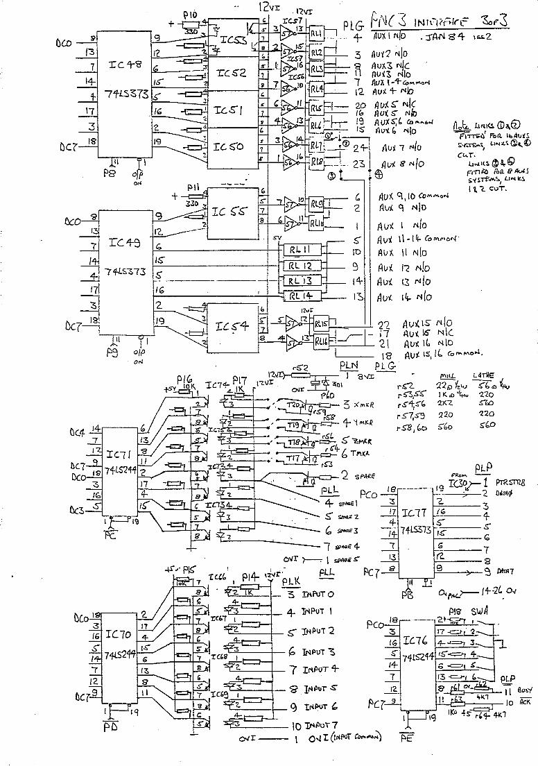
&0
DC?
tK7 Dc
~
/3
7 14-
+ \1
3 IS
<'if
13
7
/
4-17
"3
IS
Dc.o I~ 3
1: c..,..S
7tLS?!>73
0'"
rc.4-9
74LS~{3
P3 ON
IC1!
/6 r[70
g
1'2 b
IS'
~
I"
2
19
9
1'2.
G
IS'
~
+ -c=f'l
'2 -----
.... _---- ---16
~
I rc.§"4 7 a
. '-'='----1-- G INPUT ~
1......:: __ -1-_ 7 INPUT 4-
c; 2
I
S'" 1'0
9 14-IS
. :rAN 84 16. .. 2
(lob, utt\~ <Da.Q) ~ ,
Aut. q ,10 Co .... "'o,.J
(.Iv,{ q /\lIn
Au~ I Mlo Av~ \ \ -14- (0 "'",,01\(
/lux. il N!O
Au'!. I~ MID
A v'!. 13 Nlo Avi 14- MID
FI~6 ron. Ibill.lX-S ~'l:.rt ... t L."t l(." d)" ~
I
CI.<.T.
li"'Il!.~8,.G FrT1~ lOa. e A<XS &'fS-n-........ , LlN~
Ii. (. CuT.
111)'( IS !'iIO Au( 16 NI( Av~ It. Nto Avt IS, 1'- (aMMO ....
f"\tLL L4Ti!E
'125:) 'ftUJ ~b 0 '4u I K. til ",- '2.20 '2.K<' ~l:/:)
220 '220
5'60 ~bO
~~--- \0 'INPUT 7 OJ I I O~ I (INPUT ec",lI\6.i) f:>E

fOLO 4-1 Do Ib 40 IS" 39 Ilf.
3g 13 til
IJPs-so+ J_2 ___ -- DEn ______ 9 r- 12 D'o 13 --- - l.,.
---- __ 7 13 /4- to ----IS' ---- _14_ --___ __6_ Ie4$" IS-~ --- -- -_4: 16 17 __ 3 17
18 2 19
~~~~-ll~l __ I ':-r-~;;......J
18
19 iJC.l
t l!:or
ISS. '2:
\------- lo..;s
LS373
PO Dc & 13 r 11- Ie 5"8 F---i---;;-' ~
17 3
-tS"-C:~~~ DC7 18
L....,--.......-J
r- 1\
1001( PI! RS'2~'2 ~pnoN-'"P6 i; ;;;-ct - - "-
I 1211 "-\1 to,
Mo '27r-O'--"---'"'----, "-
olP ON
PL~ 1 liOFT _,,~.OE:
" ce TJ((. '2~
~--~L-~------~~-----O~ 1---__ --1 PUIs
rc.40 DsR.
oS 8'2S"1~ b
~
7" Rts
lJB7 8
PlO +5"_ As CTS
PL.O ~ - Rsr()JT
CLKI2 .. ill
PL03-R<:T~ full
-'2Z '2.
'24-
'2'5
17 4-
r--~;::h:;:;;J-----:::::-----:r---;; ------------------<. Ds R - ~ r41 R\(~
$I6/:. +1<1 r2~ ;;-t-\S
(:,rR "20 \I. J Art NO'S ~FEll..
'-0 PLF
--~-~~r-- r'3! r 1~ ~:11L~~ 3 ~ 100 4-
{9 "-- --'TO~-t- ~r~ crs-S 1 fl r3'1 {(,S,-
r-==----;.------~, -rIb _~i 4-K-1 r64 10K. r'30 41<1 '3 12.
f-----~ -;:;- 3 100 -- IJ r4Q .'''Ie, ------'7 T-'(t, - c. 41<7 11 r3b
-'6" ~ 41<1 c- 0" - 7

P4C O'lfk;>~---~
I :>

PNC 3
pLe
nl 1--5" J-+s.-bl \b < \ Y
LS 14
108
'CLR ~l
V r--- I-I
<t'} ~r g~ Cb:
C51-'~ 'f\, I I b4r.:~~B=_=;~V===3=====-~ __________ ~~ ________ ~ ,,13 ~
c.lt "'9 -1-5
SIr cs T) 5loB
RII
3 I I Z
IKo noR R7 R5
r 22R lZ20R. : I. ~:c~ R12; IRIO ~
RB
" OE:
ov-"'-
, '':
V D U
D(l)
+5
's::. :: Pol'; B'<:-
Ato 2-
At:s~ \ A:D-"t S" Art 33 \ I ~ Ao
9341 ~l
+5
0"1'1
i5
24
~ &110 A":J-
1: Ie II (",110
150 ICo
Bl-(3
b ·,114 pS 11311'2 ST R/WI 5G.SM'
Aog 2(..
SM ~ R/WI
9340 BG 20 BS
(3(, 19 -
81 18 B7
Ie 1'2 AD 3"- AO
37
A3~ 40
'Z
3 sL 2
Ie 130111
? ~ 2.3 A 22 ~9
13,"1-
-'--~-ov
------
_11.11 Ie 14 AD}-U A<J 07
RjW!21IJe: 5M
-'---'---'--0 v
---------__ ADDITIONAL -- GRAPHICS cH~Rl1aERS
opnol'l· ---P\D7 -rBO~
. :\ - II
~-I 14
-- +5 T'20
LS J74
t6
110
'f114 LS
257'12' ?
,{.3~ Ie 15 II Y/r 1'2.
SELEC.T
UI.L=I' ov :I
I~ ) 51~I.K'::I''';i_' krW1 A? I
) /s-c,. 3,4,5 14LS 10
AD4~ 2 / CD; I:;'~
/ I I'
PLe VIDEO olr ~ ~.
ov o
--'---'---'- 0
A?

WR tILE
ICC;
f?>P£ ltc/1-
~--_--III-z.
Rot II ,""'/
SJ '244-
11
Jf/'"iY\ 9 ---::-l-!-
3-:5
830.1\-~ ~~ ~ !1. !l
CY7 12.
8f1'1u~
~ '2.
IG 5 IS ~ !£.. '3
!.Qt 9
1C7 '27'1-/ 27/'28
!.L fJDrj> 11 !1. IS"
le8 a..s LEFT
b 14 ,
nl/~'ICI7 ~ LS I:: I
Ar2"3 139 A 10 ...
\rJ~--
PeW D¢
I~'"'''''''' . 1'-" LS
:'.'-:/
N.E E PNC3 PRoc£~RI K£'IEoIk!O '~e2 19a+_ --1--:- .
24-4-
rio
r9 '1--., p¢,J
LS 5 I 313 is l' 6
. I ~Il
D7
I b¢
~--- " /"6 1'2 e;cr .,,'lee. bl 01 e 9
IC<j
AS LE FT
A¢-1! fll~ 112~
o,~ IC3 M- 6 ~ $" (,11(, /16 In ;3
1/8 tl9~
cE" DE"
, 1'3
Ie 2t;, '2 IG
- LS S' . 313 IS"
G 1'2
r rL I). 19..1. "25"8
,
Ie 25" 17.s9
1+ 't L5 15 (,1 2~4- 6 Q'
1327 :
82& II~
c ....
T(IO Ie II Al:. l~fT A!> LeFT
I L-,.-~
~WR
~r TC+ I IeS-
bll(, J As LEFT
LS~b
~ 19 flD7
A
'/
. KE BO(l~ o sw rc~f<: S'vJI ~o S\tJ, I +
6+ .st> 4-1. ~ -Sg "so 34· r6
41 +~ :S'?l ~ r:I ~ .$"1 I
~b 52 4-'9 44- 'fO b ':sG ib::: S7 53 49 'fS 41 ~"3 ";57 ;:e 22 It? ~ II ' 7 31 ''rT' 23 Ie;} 8 14- IS' 12 3'2 ~ 2+ 20 ~ 4- /6 13 .'r3 2S' 21 10 :5 17 2 ... ~ ..';-;;;!

BLOCK DIAGRAM or PNC 3 CONTROL UNIT.
REAR PAN£Ll 1 I· ON SWITCH ROt-ITPANE LOG~~C SToP AND oN T<'>
At-ID FUSe:. SWITCHES 1 "A.NS
I I C~&SETT£ ~"'I\Nit1' <-----------l " 5K e OPTIONA.L _ S"C P EXT£NSION UNIT CoN~OL
R _ L SWITCHf:.5
SI NGL£ OWER PLF + 5v -C;N P A MA.RD r-__ PHASE -" PI-A DISTRIBU110N tl'2.vl: SUPPL.IE5 'E j
M~N BOARD PoWER I r-;::S71( El::-----PL-LA~ r-- SKE +5'1 T IZv t 12v: \. + 1 '2. v N
-Bv SUP'Pl.IES/INDS/rusES 7 T
, . / OR,." CONT.OL I, ~ PRoCESSOR/ DRIVE." l\1..c A.
FAN I-- iRAN5F'ORMER' OVERTRAVd F\.. a. G KE.YE:>OARP !\ND 55vSUPPLY 1-S - - - -( SIGNALS I '-' E .
± y g I ~PTION/l.l. F
I S N I !\OOITIONto.L RS 123rfL B I T N I AUXILLIARY _, 0
AXIS 1 DRivE 1--- DRIVE 'i. MarOR~ I £ E fCONTROL I I-"L ~ A PL D Pl. D P. C. '6 1 M C I"ANA-LOGUE: R
lAXIS 'Z DRIVE' 1--- 24v YMOTOR\,. IT:'. OUTPUT I Pl. H D SUPPLY 7 1 I \.1 NPLlT SWIiC~ A-
IAXIS .3 DRNE r- ~~e:. 1 MOlOR\,. lor SIGNALS I K MaroR 7 I N I> SPARE INP~ rc r-----~ I='USE· I S I OPTIONAL
I AXIS 4 DR/YE L-JsuPPLy' T MOIDI(\,. I I 'DA1U~ DETECT OR A.. P E .1" .1 ! I'NDe. ! (w.) 7 I I SIGNALS N L l'T':'",-",ION
. RS '2.3'2. ': RS'23'2 I PL·f BOA~D 'Z. ... 7 PIN DIN (Re:.A.R P.A.NE.L) I, - II Dt>.TA.. 1 M SK C
<. 2~ P'N eo"'NE.c..TOR (R.EAR PA.t-IE.L) P~"'-lTER INTERFACe: J PRINTER.PC. P --" + l'Zv V PL C
V. D. U. f-- ;;~~E. r- ~ PNC 3
...,. t)(T V,DEO Re:A~ PANE.L. ~~_ ,Olp V.D.U.
"---"---------------------

1--FROt-JfPA.N£CisTOP .L~N··I PN C3 P OWE!? Ol5TRl BUTI ON BOJ\RD.
PO FR M~
I I' ... - - -
IR£~RPA~; I IPW
n 1111-1-'1_1:- LIVE TO MACHINE ,';" -0", rl liT .~ ~)~ 'I F'RONTJ I ~r- I ill 2 4 .3 5 6 I PANEL I 4 5 I PL. A;¥" L...I- - - -t- - ! CONN CTOR.
'--EI--- - -r-----.- .----.. - .-- ... -- ------ __ _
51( ell I 2 3 J ~ rVER r- ' I E - I r-E
)M E - I R~ ~ I'=>I CHINE lID.,; 3 l - 2 - . ~
POINT, .1 I B r-J - '1 .. D( RI 1
,J I 1 REL~\ : 'J<l- ... C I 5 \ .IIOI/J ID* N E. L N\ l~:---
I \ II STEPPE MAINS FILTER. '-- DRiVe: TRA.NS.
N L --r-- ---,., . tl IA. 12 PL F:
LOGIC T~At-.lroRMER I I , lOBI : ~7ooll'" .12vl si::g (2v:t 3',4 ..
r- b J r Tov I ~ I K R '2
I 4 0 A - I C6JI~D.3 _____ -J -t3v 5
2 I C ~ • .J 1 I cs i R~ I D2 ;;;- ZaO/11<> 220
! I . r 3 2f2Aoo 1 g'tVI P 0 : b....J ~ hJ I ~~5'" I . ..J TI~JR70.22J\. f?Sfl'N c41 LI I t-J ..J:: + ,,,
4700/~ 47~~ ~b .J!1.J9.. 10 . .-1 J 4K.3 u:: .$ 2LI----t-~ 0 v rmn c"rrrl. c: DB.3 C2-r- h, Ie I 3 _I R('" ~20 r../
8 1 C3 5 723 CIO loofF 5K"- R4 110 \0" 7 13 (/ 1«0
. 9 / VRI 10 12" .. 2KO 11;'-'-----;. II
'--------1 , -----I I'Z. ~v I 5v. - - --r-- n I TIP41~ _~'22 l +5v 9.10
~ sk ~ ~;n~~' 210 f f ::~ ~ 11,12
DB2. 10000 IQOOO Z ... 7 -~IC 2 3 ' r9 /10 /10 I RllbI123~.. I R9 1(3 1.10 C7 C8 lOA T ~!" 1 cli'loOrF" ov \·5 27()i I1b
'---------------~ Ib I -i"VR 2i,' 1 1:3,14 Pl F L '2.K'0 15 Ii> .'
ov~
I
To R
I OR.l1ER
JTO 'IOU
TO
INTERF"A.tE
BOARD

VR' PROGRkMMABlE Ie M 370 I CONTROL X AXIS CONTROL C XY{Z) TIMERS CONTINUOUS OOH LOGIC OPTICAL \ SPEc 0 _ CoNTR.oLLER 0 I. I C:s 114· +LOQ.IC. ISOLh·no Y AXIS CONTROL.. VR'2. l-n1i I I I . rC •. :ld.9,IO,II,12,13,IS " N ~) SPEE.O ~I~~~bs , I J>.l(lS sTep I?S~- Ie s Ie.s _~ Z A)(IS CONTROl. N
L /CI~N SIG.N",LS ,-,
Oe.USA,XIS AcICNOWLEG~Sla/J1"I..$ 17, 3'2.-35 T .... )(15 CONTROL E "'l(lS BoOS" SI i»NAI.S 2 9 C POI(TS 4 .... 4c. ' Ic'$ 71f 31. T
I r x _ 0
E 1\)( IS . W A,XI S C r;,::;'::~-l--~l/~------::-:,...-,::--------1 R
DAT" OVE.R.T.R."'V~L OIJER.T A,ve:L LOVER- 0 'OPT'CAL 'I DI<I'Ie Sus ",Nt:> DR.lv.. R TRA>JiL N l"~L.T SIGNALS LOGIC 't N - ISOLATION Z FAUL.T
FbRT4.e. IC '2t> Ie '21-24. T S'l'hTC.II! ~ re', 3Z-3B T SleNA-LS C ~ -
DATA "~p ~ ~RT ~SP'"OL< He DATA SP~~C 0 p .... TA I euF'FER.IN", ee.c-oDING ~us' CONT~oL ~ Sus A,NC CoN~L uS I.C~I ''',16.lS 20.44 PoRT ...
IC',41,43,45,ib 47.70 Ie's 50-65 H
O",ON,L ~c ~RELAY C ~OAWM C DAT~ I ADDITiONAL 0 D DRIVE5 0 OAt D .. ,-aC.1l:lR 0
BUS R,S 232 ~ Po~s 8,9_ N L..ocac. A"iO '" LINK N Bus SPARe ~N N
fi,ltTb,Ie, 40 41 F' Ie', 4(3-57 G T,,(b~T.c s N
'NPUT ~c ~ R,'N",' HCU~"'·'-5IGN.A.L5 0 D DA..TA. ~ D SWIUHD
FbR..T D ~ Fb~ B N PRJ NTt:R
us Ie 77 p us 'STA"L.\.S re, (",b-7o K Ic7b f6R.TE
PNC 3 INTERrACE E:>OARD

REAR PANEL ON SWITCH
./FUSE
E.
.. ..
E
SKA.) L 1-' MA.INS
\ N 1- FILT£..R
1 FRONT PANEL
" 0 v SWITCH I A.ND Fbwt.R LATCHING LAMP
1 RELAY
AND
~ ONN
INDICATOR DRIVE
COMPONENTS POWER
SUPPLy' SK E
LOG-Ie
TRANSFORMER 31(,1::
--+1'Z.v ):i
POWER
SUPPLY A-ND
Fuse:.
+ 51/ }i
PowE.R
SUPPLY
r:ust.
I'2.VI 'A POWC:R
SUPPLY
rusE
I -8" i=evv!:R. Su ..... L.'1f
·1 I
CONNECTOR F TO INTERrACE
BOARD.
BLOCK DIAGRAM or POWE.R DISTRIBUTION e,OARD.

PNC PROCESSOR BOARD BLOCK DIAGRAM
....---- .--
C C RESTART XTAL,
I 0 0 AND E PRO MS
SERIAL
N N DATA
N N B U F"J="E RS
E E
C C CONTROL R A'M S SIGNAL
T T A.i'-.lD 8055 0 0 ADDRESS
R R BUFF"ER
/lATCHES
CASSETTe: .--- PROGRAMME.
D. C, CONTROL C.ONTROL SWI TCH
r-- ..--
I PORTS PORT
)
DATA KE.YBOARD 0/
BUS CHARA.CTE.R POR.TS
KEYBOARD. BurrER f--- '---

CONN C
lc l, 1.2,
I-
BUS
~ DAM Bus
U ~ F £ R
~
DISPLA.Y CLOCK.
Ie.. \0
~
/
"
I II, I ~i:JcS A.e A~
r--
CHARACTER GENERATOR DATA INTERFACE
Ie II
T
VIOEO I NTERF'AC e::
ICI'2.
l I EXTEND~D CHA.RACTE R
GENER,AioR
BUF~ER/ DECODER
Ic~ I"', II, 18
l
PAGE MEMORY
rzSRows of
40 CHARA.C~ RS
Ie I~, 14.
1
EXTENDED CHA.RA.C'TE R
GENERATOR
MEMORY ICIS
P N C 2> V 0 U BOARD BLDG\( DIAGRAM.

/
ENC 3 External Connections Layout
CRT C01 C02 INPUTS AUX

rG~· OvI 12vl @ Ov
«1+
IC A I
o~ C
TO C2
FILTER
C3 N L 01
-(C}o
A8
0 VR 2
C7 +
RIO RII IC 2
C8 +
~----- - - t'"I ca
R!LAY
~L[I= ________ J D~~D, _____ .....I~ .. EELTD Pow.r Dlatrtbutlon Board "_2 +
~-.. ' •• - -...-_ .... ~ I:~". .. •• _.

r ABC \I
IC1
II tC8
SKA
L
<.
IC2
IC25 I I r9 II tC1S tC17 0 II 0 I I
I c:c:J c::r::::J c:r:::::J \I +IC19 I C2B IC30 I I
OtC9 otC11; ~ Q ~ {TI ~ () 0 ~~ 1C21 ~ I ~WJ r2~ T6: I
3 ( ) ( ) 1 • C • P8 9. T71 I 2 6
t C 3
IC27 1
T12
IC10 IC12~{~ II tC40IC1061~nl1~ II ~ 141C24
2 34 ~ 1 T16 P
OO~OO OOO~ ~ 12VI
RL7
~ R R L L 8 1
16
L
PLO 26
S
_ !nJ~a~~ _. atv
-----.-----.
24
PLG 21'";:I::::;R;:L=14=-==~ RL13 SKE I 16 1 I I -----,
30 1---------.1 ~. =====::::::
::2, ~ , IT~ ~+]~ '~6+: 8. ___ .1L. _R_R:_,:_2 ___ ....
1
:: i 0 : 0 ~ ~II ~~n ~ 9 ICS5 t<;;7.!~J. RL1
II + IC47 0 ---li ol RL10
R L 3
RL9 r50 = S
IC78
SKJ
= K r51 M RL2
PLL
• 40 IC72 1 0 = 052
. 6 D Q~ 'b1 II ~ 1 "' ~Ip
t F D1 lOO OO~U6 ;n;14 f15 te70 : 0000 0 r ~ II ~. f6- gOO 1
I I I I
lOU
tm'"
Ov 5v
PNc3 INTERFACE iss2
North East Elect ronics Ltd II
, ... ----~-... --... ~ ---~.-. -' ---- --~~~-.". .~~ .. ~. - .... - "-.~ .,-..... <""~

r I I I SW 1-7
SW~-1O
SW11-M -----,
SW15-17
SW18-21 22-25
Or1
Or2
Or3
Or4
+- North East Electronics Ltd,
.. " .
26-29
~ SK.B 1 I rf?r---- ~
.J
/I~ §5~ ~-~--~:~ C20 ') 1
0 I ,
~ C70 IC7 ..
c 5
o
IC3
IC9
c 8
o
c 9
o
IC4
IC10-
c 10
o
c II
o
IC5
r 12
r r
IT314
ICll + TID C
cl2
A~
+C3c4 10C" ~ i'OC16 OIC:
q :t IOC18 IOe19
()O kim n
ICI 0 P
~ Spare
~ 1 = SW3C>-33 34-37 38-41 42-45 46-49 cl3
u ~~I 4
~~I 1
!~I ~
!~I 1
~
v
r5 = r6-8 E5 = c2 =
-I I
I I
.,
!
J Keyboard Issue 2
OA" ~~bo~oW I 'm' ~!A I PL.D
IC ~ 7 13 SK,C r-, I II
~5=~ I
101 I
I
~fr~ U §
r----~ '" V'
. ____ L~ ,
.=--t

o m z 'TI o :0 9--" i: » () x z m -I o o rCJ)
r.-I o
'" ~
m
PNO 18 8
GRN OIT LIS 33 (OM OVI---' ~----~=----,-----..,.."..
RED -X OIT __ ~' ({2-634~RTRAV7S 2 LIS Ne. " 7--<: ---'~::>....-n'..u.....~ f--
3--i Yl.W t X OIT : (02-7 35 +X OVERTRAVEL
1-'-=--'- LIS N.[ <~ !-'-4--i WHE -Z OfT • C02-CO -1 OVERTRAV~L 75 __
LIS N[' ---<~>---~ BLUE +Z OIT __ .~~AVEL
1----1 LIS N ( . - -5
6
PNC3IB N
C1 2
3
4
PINK DETECTOR 3 e COM BV! --:------::...::..---
VLT X DATUM' (02-11 39 DETECTOR---<~--'::"':----'-:":~~~
ORE Z DATUM (02-12 40 --nETEC TOR ---<~---'-=--_(O
5 BLUE SPINDLE (03-12 50 I--_-II---:::R. p. M.E NCO'5ER'-<~
6 YLW SPINDL E (03 ,
I----E NCOOE~'< 1Kn
PNC3 PRIV£ BOARD
X1 BRN X MOTOR C021
PH 2A « Xl ;REO XMOTORC02 2
-- PH 28 ---.--< < X3
ORE X MOTOR C02-3 --PH 18 ---«
X4 nw X MOTOR (02-4
---PH1A -----<-<
,~ __ 41 ___ ~_K_i_W_T _______ ' ______ . _______ ~
42 BK r~ ~ -r---4- 3-, RED_::._~--:~~~k: :-0\ J1:T6~~. <--_4_4 ___ RD I WT ___________ .. _._~~~::. .. _. _________ J
GRN Z MOTOR C03-1
Y1 PH2A --_.--« :--_..:..45::.. B~ ___ . __________ ... __ . ___ ~
Y 2 8LUE Z MOTOR (03-2 46 IlKI WT
r-::-:.::.::.~ PH 2 B ----<~ -------1----1
_'y'!:!""""Z MOT08...._ S-%3-3 47 REO MOTOR
GREY ;~ ifz R __ ~ ~-3~-{,-4-'-e'-----'-'R.::.D/~W:.;T-- --'-'----- • __ ._,_, ____ -=-.~
I o ()
2
21
3

,~, ~ ,
~ ~
0 m z 'TI 0 ::a 0
3: > ('j :t Z m -I 0 0 r UJ r--I 0
CD ::a C5 :t 0 c: UJ m
CI
~I ~ ... » :z a :z
X STEPPER MOTOR ~UM .z OfT LIS J
10
, _ l:;a i, __ ,,_,, __
PLUG (ONNEC T IONS 1""- --,-,----,,----,--,,-'---.- ----""",- -
_( [_O_MB_IV_E~:.:,:n __ _
I CONNECTOR (01 24 WAY SOCKET (REAR VIEW)
1 2 3 4 OlE .3(21).4(N) a5(65)
5 6 7 8 1116( 14) ~7t11lt III
9 10 11 12 • 0166 .69 •
13 14 • • ~60 1J 21 22 ($57 01
15 16 0155 .56
19 20 01 59 0158
23 24 .. . ONLYUSEO ON MACHINES WITH
(0 MMANDER SPINDLE DRIVES
CONNECTOR 4
1 .19
2 .70
3 11175
4 11116
5 0116
6 11133
Z STEPPER MOTOR CONECTIONS
CONNECTOR C02 12WAY SO CKET { REA R VIEWl
NOTE'NUMBERS IN BRACKETS ARE FOR 3PH H/C
1 2 3 .41 .42 " 43 4 5 6 .44 11133 11134
7 B 9 .35 _36 01 37
10 11 12 11138 .39 -40
GUARD 'LIMIT SWITCHES
~-:; 'I -
I
! BI</W 46
RED 47
ROt 4&
I o (')
( ONNECTOR (03 12WAY PLU REAR VIEW)
3 2 1 .47 (146 .45
6 5 4 01 III 11148
~ 8 7 0133 III " 12 11 10 01 • "
I CD
2
4
6
10
II
I~
13
15
18,
19
2t
21
23
24
25
27
28
29
31
32
- 33
34
35-

I I
____ 1_
,.v .. _.~ ...... .."_ .. ~,-.....,,.....--. "",.~ ... ~ .... !:",,", -, :".-F,"," ,":,,-~;:r_1" _ .. _----, -, ":---'-, ->~'-~
PNC 3
(- E-(01-1 E r - PD1FA1- -- - - - --, ,,)--,- OEARTH ---------,._"------,----<------
r-- ....:. POB JA3 (01'~, 4 : o NEUTRAL
» - I PO B-A2 (01-2 ':) LIVE ---- » PO 6- L
(01-4 5 :J LIVE OUT -- --- --- >>--- ,
i ------ TRANS 5 I "1 ----,. , • _~ J , POS'N
~ N
' ~ 2 I ----'--,--- \ /:\.., COl-5
6
, ONEUTRAL OUl
-'T-O : 'J -: r . , f' • <i!,L ,
'r----.. , - .0 a::::::n~ iiX>~~ ____ ~_ ,» I
' L 0-:---- "', 6 ,-'+0 n_" 67 f3 7 L _ _ .-----< . ,
' I I ,~ I
17
IF USED
3
1 I 17 I 18
fl R24/ L I~ I lOR R22 (OMBIVERT
LOW LUBt LUBE TANK L_~o,70 FLOAT ~WITCH 67 }
-~~-~---.-----( 01-6 67 I 1 BG - 21
,----'>?> >--------r-:: (L NT & LUBE ( OMMON
(OOLANT
R~&.,~,-"-.:---------_-t _~~ 68, I~G~,O~tANl ~~
• 69 (01-11 69 ') LU8E '»
OLMM 67 27
-~c¢ 2~3
/
I :-i I (OM I ' . (01-15 _____ . _____ • YELLOW >>-__~5 ______ _'_ i8-HS,
22+~~ 19 _~~ (~ 0' __ 20_, --Q \ ~r-l{) 21 ~
I ! 0 (OMBIVERT Ov ~ ____ .. _ _ _______ ., GREEN ___ (91 -165"6 ' IB H3 I DD I --7/ .:J SPEELJ OUTPUT
HPP
________ BLUE ~01-17 hO ,IB- G19 , I /)- --;----:::: (OMBIVERT .10v
I I
'
I R I WHITE ~~:~-: IB.G24
EJ-"/ ---'",-~'- (OMBIVERT
51 J. 6LACK C01-19 " ,IBG-22 REVERSE I >')---- --~
F I--
r----; 71 ~ 59 i '-24V~ ~
I I
I L_ _...J
EASI TURN 3 (1PHASE (OMBIVERT'52;
WIRING DIAGRAM S(HEMATI ( N°1
I I.
I
I ,
-------- ----'------ ~
lDENFORD MACHINE TOOLS LTD BRIGHOUSE WEST YORKSHIRE IDRAWN BY K STANTON DATE 10-1- 84 I DRAWING N°A3-300024 .J

COMBIVERT
i -I N I 18 I ---H
I L ! 17
! T 1 12
~fj R24 1
FLC !27 ,
F~~l73-! F' • i ;
-".'! " i'--Law I i -+ .. '-"1 FRQ. !
coJ~~ . REF 56
PP 60
-24v 71
'\ ~ . K 58
F 59
ST 59
T83 .r::;
.l: 17
ITs lJ1 , 2()
1~21 22 23 24 27 59 70
I 71 .
r~;-I
I I
. I
I
TB1
~E I ~L
IT E E
8°V
' b 24V '
I I
E IE
15 I A L U
16 I B B E
E IE
SPINDLE MOTOR OVER LOAD RELAY r- - ----::-=I I 67c;-:-o27 I
I 19i022 ! i 20.0- I;J _~23 •
I 21C~24 ~-
F7 72 -f" ! ---1 . L 7
I : - I I 1
\~~~6 %3 ~6» ~69 14i7i ~2
F 1
!IF USED) .
1\-T- 11 3
F 2
I 1 L-...
710 CS9-~ ---.-- .-73 h
' ,---o , 0 ..-L.. ...:....
CRt .' :Ri -. ~ ~ . I
9 --i-' 170 : 01
160 : C' ~ ,_---1
12~ y. f12v I I
~.,II . ______ ' _'';!J. ---"'----'-'-- I
Ir~ifl; . " I 6 5 J - - ----
I f I I I f I PI. _1 __ 1_
21 r n I 14
FS (LNT TB2
12v i 10 I ;: 411; - . ,-. -'-.'
ITJJ ov: 9 ;
, I : 8 I 10 ~ I ?4vl 67 I - I , , 1
:--1 E : E I
L.J
31 I I 111 . .. F3 24Y
F6 LU B I I! 311 1\14671 I !7
DE.NFORD MACHINE. TOOLS LTD BRIGHOUSE WEST YORKS IORAWN BY:K STANT(
~---.. -.~ -->--.'"-~~
I l ! SPINDL~ MOTOR i r-- ----,
I '0 1
t~ LUBE UNIT ._---
'0 l
f _. f
i 1Jor67 1 I
I I) !
L~I~~_jj Lu l 0 ;
['. f
ric
CABINET COOLANT _UNIT I ~F~SED)
Ioi ,0: Gr -t-J 4- -¥-J -
" "0 \ () r LOW VOLTAGE LOW LUBE WORK LIGHT . WARNING LIGHT r- - ---, I-~
I 'I ~R I
! r0t! ,r-®-l! II I I IJ L2L_~ LL_ 9
L ___ ~ \ =tn
EAITURN WIRING DIAGRAM MAGNETIC PANEL (1PHASE COMBIVERT)
![*2% /#49#0 %QOOGPV WVKNKUGT - MARWAN · 2019. 8. 9. · o h v u W µ v u ~ u o D µ v u E À } o } P ] v o Z u } Z } W Z r o } P ] v X u Á v X u o W } W î î Æ u o W Z À D } y](https://img.pdfslide.net/doc/110x75/5fcc330613681d70d3486618/2-490-qoogpv-wvknkugt-marwan-2019-8-9-o-h-v-u-w-v-u-u-o-d-v.jpg)
![] Ç } Ì v W d Á o À } u u } v D ] / v ] } v W ] ( o o ] v ... KDDMetricInterpretationPitfalls.pdf] Ç } Ì v W d Á o À } u u } v D ] / v ] } v W ] ( o o ] v î á](https://img.pdfslide.net/doc/110x75/5e5aafae9c24815d6a60d90f/-oe-v-w-d-o-u-u-v-d-v-v-w-o-o-v-kddmetricinterpretationpitfallspdf.jpg)
![o o } ] u v } o o o ] } v ] À } o ] o o [ } ] v - Salute · Ds W D o ] À v } W,D W W } o ] u ] o v ] P µ v ] ^s^ l s& W ^ } ] Ç ( } s µ o ^ µ P Ç l u ] v s v } µ & } µ u](https://img.pdfslide.net/doc/110x75/6037a1c8fef07f441d576b56/o-o-u-v-o-o-o-v-o-o-o-v-salute-ds-w-d-o-v-wd.jpg)
![Fiche d'inscription 2020 - 2021 finale - ECOLE WUSHU BREST · EKD W W v } u W v ] v W W D ] o W : [ À } ] o o [ ] v ( } u ] } v o [ } o d o W W } ( ] } v W](https://img.pdfslide.net/doc/110x75/6052aaad5877952e5739832a/fiche-dinscription-2020-2021-finale-ecole-wushu-ekd-w-w-v-u-w-v-v-w-w-d.jpg)
![^ o u v Ç ^ Z } } o · ^ Z } } o E u ^ Z } } o d Ç 9 W } ( ] ] v > 9 W } ( ] ] v ^ Z } } o E u ^ Z } } o d Ç 9 W } ( ] ] v > 9 W } ( ] ] v](https://img.pdfslide.net/doc/110x75/5f9e72566b71671f0c478d78/-o-u-v-z-o-z-o-e-u-z-o-d-9-w-v-9-w-.jpg)
![Variant workshop part1 2017 - Cornell University...W r o ] P v u v o v r µ d ] u u } u ] W ( o Æ ] o ] u u ] v P } } o ( } / o o µ u ] v E'^ ~ } o P o X U Z W l l Á Á Á X µ](https://img.pdfslide.net/doc/110x75/5ff4a69810f9f96a8f527f37/variant-workshop-part1-2017-cornell-university-w-r-o-p-v-u-v-o-v-r-d.jpg)
![v ] ] À } W ] v ] } u ] ] o } } o o : µ À í ô v } K v o ( ] } } o o ] } U ... , ^K W E/ 'h U 'KE >K KE ' Z / U D/< > KE U W ZK } o W ] v ] ] v KZ Z ZK U D Z K^ } o W](https://img.pdfslide.net/doc/110x75/5b40cac57f8b9a5e528da298/v-a-w-v-u-o-o-o-a-i-o-v-k-v-o-o-o-u-.jpg)

![AULA 12 - AULA · W> d &KZD t W o ( } u ] W ±& u v µ ] o ] Ì o ] u /& Z E X X X Z ^ ^K / /^ d u } o ] } v u v } v } U Æ ]](https://img.pdfslide.net/doc/110x75/602de165dfafe12bfb6af673/aula-12-aula-w-d-kzd-t-w-o-u-w-u-v-o-oe-o-u-.jpg)

![A Constituição Divina Richard Simonettibvespirita.com/A Constituicao Divina (Richard Simonetti).pdf · W ] u ] W } } W o µ o ó ð u } } v ] À o o } µ o } U ] µ o u v µ](https://img.pdfslide.net/doc/110x75/5f42164cf1223c540c1711e7/a-constituiffo-divina-richard-constituicao-divina-richard-simonettipdf.jpg)
![PPT PresentazioneAziendale Seminario Trieste 06062019...o } P } ] v u } o ] /D ~ W W/WW } i / u o u v ] } vW o v W/DW } i / v ( } u ] } v D } o D/ WD / v ( } u X o ] À Ç W o v h](https://img.pdfslide.net/doc/110x75/5f92405b0cb65d72131b3791/ppt-presentazioneaziendale-seminario-trieste-06062019-o-p-v-u-o-d.jpg)
![À v } } } W v u µ } ^ ] µ } W } P u & } u } ' } } o ~WZK' W Fina… · ' } À v } } } W v u µ } ^ ] µ } W } P u & } u } ' } } o ~WZK' W](https://img.pdfslide.net/doc/110x75/5f6aee27c8e6717871591876/-v-w-v-u-w-p-u-u-o-wzk-w-fina-.jpg)
![v ] µ ] } v o & u Á } l } ( Z v ] r } µ ] } v } u u ] } ( Z W o ] u v ......W } o ] Ç ] ( ^/ v ] µ ] } v o & u Á } l } ( Z v ] r } µ ] } v } u u ] } ( Z W o ] u v } ( D }](https://img.pdfslide.net/doc/110x75/5f7117e4e9dcaf79a54a145b/-v-v-o-u-l-z-v-r-v-u-u-z-w-o-u-v-.jpg)
![W µ o ] ^ À ] } u u ] ] } v U t v P opscwbapplication.in/pdf20/QUALIFIED_ROLL_NO_WISE_LIST.pdf · W µ o ] ^ À ] } u u ] ] } v U t v P o. W µ o ] ^ À ] } u u ] ] } v U t v P](https://img.pdfslide.net/doc/110x75/5fc6d1d4a81937160f43fa0c/w-o-u-u-v-u-t-v-p-w-o-u-u-v-u-t-v-p-o-w.jpg)
![BULLETIN D'INSCRIPTION PRATICIEN HYPNOSE...v ] ] } v ] ] ] } v W í ò õ ì } µ o ( } u ] } v } u o X & ] o ] ] u v W ï ( } u µ o u } v } } i Z } ] ] W r W ] u v } u v W í](https://img.pdfslide.net/doc/110x75/5e332bd64e50b926991671b6/bulletin-dinscription-praticien-hypnose-v-v-v-w-.jpg)

![Adela-Damosso Texto Edicion - Ágora Marianista · W } o } u } } > > , ] } ] Ç o s ] ] ] v } ] P ] v o W W } o } u } } U o U o ^ } ] o s ] X](https://img.pdfslide.net/doc/110x75/60487a9255dc991106720bb0/adela-damosso-texto-edicion-gora-marianista-w-o-u-.jpg)

![W o v v d } o / u o u v ] v P À o } ^ } W } i / ] ] } v Æ](https://img.pdfslide.net/doc/110x75/61bd19da61276e740b0f5c07/w-o-v-v-d-o-u-o-u-v-v-p-o-w-i-v-.jpg)
![· > } o ] u } ] } v U À } µ } µ À Ì P o u v u o Z } } v o ] P v µ W ] o µ u t X W } µ o U](https://img.pdfslide.net/doc/110x75/5f283f889046467f00201f61/-o-u-v-u-oe-p-o-u-v-u-o-z-v-o-p-v-w-o-.jpg)
![} Ç ]PZ W ^ u o u ] o](https://img.pdfslide.net/doc/110x75/61e549ff81a77968fa5be724/-pz-w-u-o-u-o.jpg)
![W } ] o ] Ç · Ç Z µ o W u v t^ } v ~W ð u } W W u v t^ } v tE } o ] ( ~> í ð í](https://img.pdfslide.net/doc/110x75/5c12924c09d3f224238b4624/w-o-c-c-z-o-w-u-v-t-v-w-d-u-w-w-u-v-t-v-te-o-i.jpg)
![Æ u o & o } ] v P W } ] v & } u](https://img.pdfslide.net/doc/110x75/616a3d7b11a7b741a35056b9/-u-o-amp-o-v-p-w-v-amp-u.jpg)
![W } o Ç u r s/ X W } ] u v ] µ](https://img.pdfslide.net/doc/110x75/624eb863cc46354fb3067cc9/w-o-u-r-s-x-w-u-v-.jpg)
![> v } } u u µ o ] o µ u v } µ o ] } o ] o W - LeggiOggi](https://img.pdfslide.net/doc/110x75/6258b0106cfa982ca60c4dbb/gt-v-u-u-o-o-u-v-o-o-o-w-leggioggi.jpg)
![& Z,' v o , } ] o v W } v o h À ] W v o À ] } Ç } u u ] D](https://img.pdfslide.net/doc/110x75/6238bc63ab26824ba50f3860/amp-z-v-o-o-v-w-v-o-h-w-v-o-.jpg)
![W> W> Z µ µ } & } u · ' v Z } v } ^ ] u W } } ^ } ] o } D ] o ] & } u Z ¨ õ ó U ï ] o Z](https://img.pdfslide.net/doc/110x75/5f8a17267734d7746f5a06ba/w-w-z-u-v-z-v-u-w-o-d-o-.jpg)
![d ] } & o Zarfaria/MT717_03.pdfî ì d v } ] o Z u v } _ ] Z } o À ] ( } u } Æ ] À W ( } u } W o ] î í o d u µ W v µ u v } v } o À v W ( } u } } & o µ ! v ] & o µ ! v ] (](https://img.pdfslide.net/doc/110x75/5f95e52fcee3e735334a650c/d-o-z-arfariamt71703pdf-d-v-o-z-u-v-z-o-.jpg)