Embed Size (px)
Citation preview

ORNL/TM-2017/468
Oak Ridge National Laboratory Gate Precast Phase 1
Lonnie J. Love Brian K. Post Alex C. Roschli Philip C. Chesser
September 2017
Approved for public release; distribution is unlimited.

DOCUMENT AVAILABILITY
Reports produced after January 1, 1996, are generally available free via US Department of Energy (DOE) SciTech Connect. Website http://www.osti.gov/scitech/ Reports produced before January 1, 1996, may be purchased by members of the public from the following source: National Technical Information Service 5285 Port Royal Road Springfield, VA 22161 Telephone 703-605-6000 (1-800-553-6847) TDD 703-487-4639 Fax 703-605-6900 E-mail [email protected] Website http://www.ntis.gov/help/ordermethods.aspx Reports are available to DOE employees, DOE contractors, Energy Technology Data Exchange representatives, and International Nuclear Information System representatives from the following source: Office of Scientific and Technical Information PO Box 62 Oak Ridge, TN 37831 Telephone 865-576-8401 Fax 865-576-5728 E-mail [email protected] Website http://www.osti.gov/contact.html
This report was prepared as an account of work sponsored by an agency of the United States Government. Neither the United States Government nor any agency thereof, nor any of their employees, makes any warranty, express or implied, or assumes any legal liability or responsibility for the accuracy, completeness, or usefulness of any information, apparatus, product, or process disclosed, or represents that its use would not infringe privately owned rights. Reference herein to any specific commercial product, process, or service by trade name, trademark, manufacturer, or otherwise, does not necessarily constitute or imply its endorsement, recommendation, or favoring by the United States Government or any agency thereof. The views and opinions of authors expressed herein do not necessarily state or reflect those of the United States Government or any agency thereof.
ORNL/TM-2017/468
Advanced Manufacturing Office
MANUFACTURING DEMONSTRATION FACILITY: GATE
PRECAST, PHASE 1
Lonnie J. Love
Brian K. Post
Alex C. Roschli
Philip C. Chesser
September 2017
Prepared by
OAK RIDGE NATIONAL LABORATORY
Oak Ridge, Tennessee 37831-6283
managed by
UT-BATTELLE, LLC
for the
U.S. DEPARTMENT OF ENERGY
under contract DE-AC05-00OR22725

iii
CONTENTS
LIST OF FIGURES ...................................................................................................................... v Acronyms ................................................................................................................................... vii Acknowledgements ..................................................................................................................... ix Executive Summary .................................................................................................................... xi 1. Introduction ........................................................................................................................... 13
1.1 Project Objective .......................................................................................................... 13 1.2 Project Background ...................................................................................................... 14
2. RESULTS AND DISCUSSION ............................................................................................ 16 3.1 Patents .......................................................................................................................... 25 3.2 Publications and Presentations ..................................................................................... 25 3.3 Commercialization ....................................................................................................... 25 3.4 RECOMMENDATIONS ............................................................................................. 25


LIST OF FIGURES
Figure 1: Precast molds .......................................................................................................... 13 Figure 2: Precast parts ............................................................................................................ 14 Figure 3. Left: Molds for precast concrete are typically manually assembled with sheets of
plywood that are surfaced with fiberglass-reinforced coatings. Right: Precast concrete
piece used as part of a building facade. ...................................................................... 14 Figure 4: Target Building Design and precast window fascia. ............................................... 15 Figure 5: Mold drawing .......................................................................................................... 16 Figure 6: CAD model ............................................................................................................. 17 Figure 7: Mold in ORNL Slicer.............................................................................................. 17 Figure 8: Toolpaths for mold .................................................................................................. 18 Figure 9: Printed A06 ............................................................................................................. 19 Figure 10: Cutting pattern ...................................................................................................... 20 Figure 11: Cutting pattern ...................................................................................................... 20 Figure 12: Final mold overview ............................................................................................. 21 Figure 13: Over grown corners................................................................................................ 21 Figure 14: Final mold closeup ................................................................................................ 22 Figure 15: Repair section........................................................................................................ 22 Figure 16: Pattern within form ............................................................................................... 23 Figure 17: Installation of reinforcements ............................................................................... 24 Figure 18: Final part ............................................................................................................... 24 Figure 19: Side view of final part ........................................................................................... 25

vi

vii
ACRONYMS
AMO Advanced Manufacturing Office
BAAM Big Area Additive Manufacturing
DOE Department of Energy
EERE Office of Energy Efficiency and Renewable Energy
ORNL Oak Ridge National Laboratory

viii

ix
ACKNOWLEDGEMENTS
This Oak Ridge National Laboratory (ORNL) Manufacturing Demonstration facility (MDF) project
was funded by the US Department of Energy (DOE), Office of Energy Efficiency and Renewable
Energy (EERE) Advanced Manufacturing Office (AMO). This project was managed as CPS
Agreement Number: 24764. The lead organization was the Oak Ridge National Laboratory (ORNL).
The project duration was from July 28, 2017 through September 1, 2017.
The project partner who led the design and testing of the patters was Gate Precast.

x

xi
EXECUTIVE SUMMARY
Objective and Tasks. The primary objective of the project was to demonstrate the viability of using
carbon fiber reinforced ABS plastic and the Big Area Additive Manufacturing (BAAM) technology to
rapidly manufacture molds for the precast concrete industry.
Results and Conclusions. The results of the study demonstrated that the BAAM process could
rapidly manufacture molds suitable for precast concrete manufacturing. A second phase of this
project will focus on exploring more challenging geometries to aid in identifying limits of the
technology.

12
13
1. INTRODUCTION
1.1 PROJECT OBJECTIVE
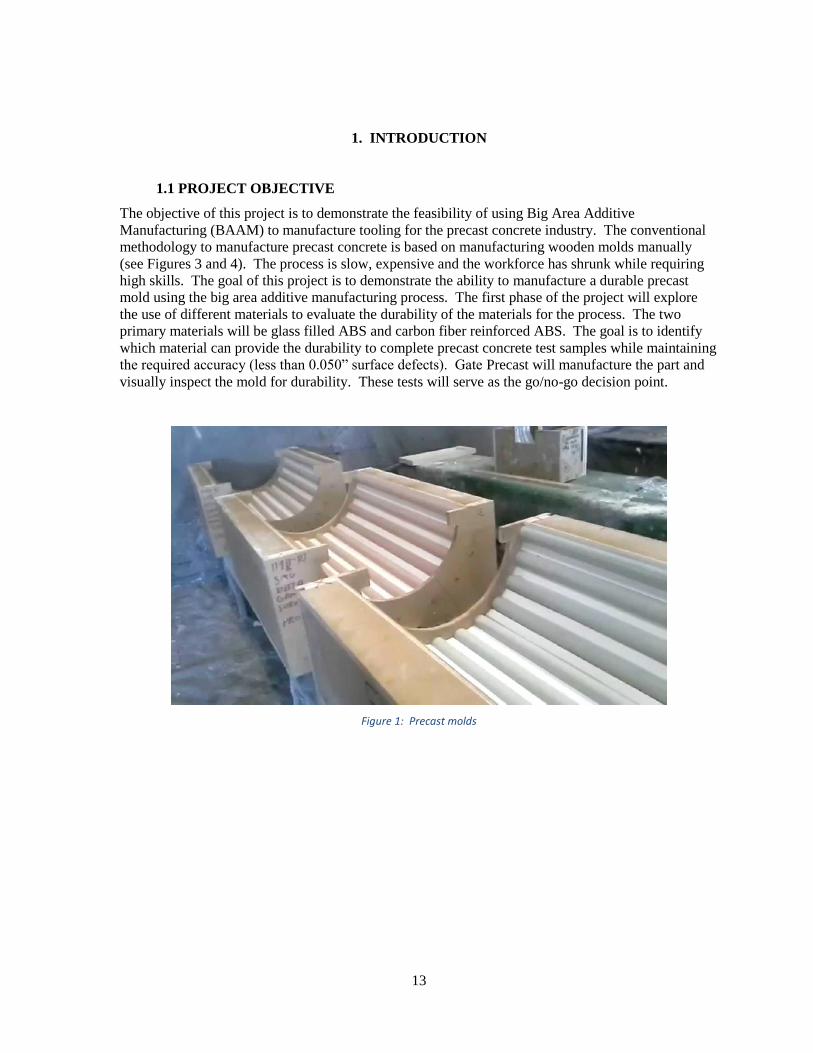
The objective of this project is to demonstrate the feasibility of using Big Area Additive
Manufacturing (BAAM) to manufacture tooling for the precast concrete industry. The conventional
methodology to manufacture precast concrete is based on manufacturing wooden molds manually
(see Figures 3 and 4). The process is slow, expensive and the workforce has shrunk while requiring
high skills. The goal of this project is to demonstrate the ability to manufacture a durable precast
mold using the big area additive manufacturing process. The first phase of the project will explore
the use of different materials to evaluate the durability of the materials for the process. The two
primary materials will be glass filled ABS and carbon fiber reinforced ABS. The goal is to identify
which material can provide the durability to complete precast concrete test samples while maintaining
the required accuracy (less than 0.050” surface defects). Gate Precast will manufacture the part and
visually inspect the mold for durability. These tests will serve as the go/no-go decision point.
Figure 1: Precast molds
14
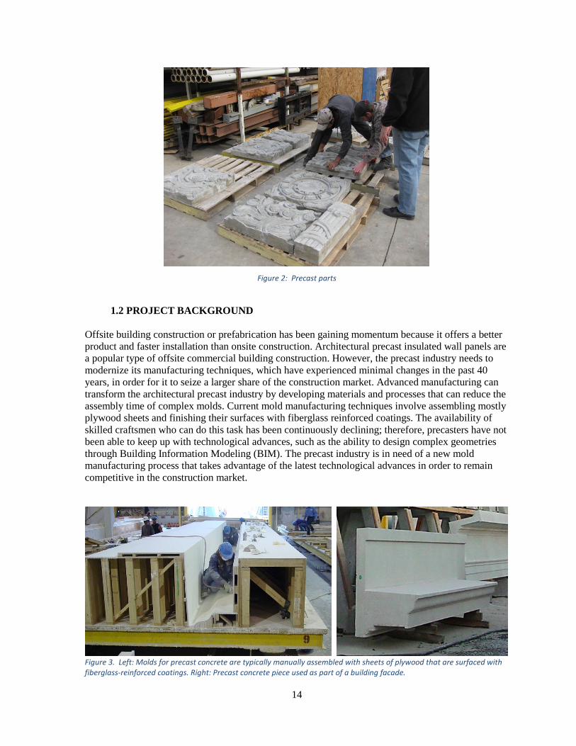
Figure 2: Precast parts
1.2 PROJECT BACKGROUND
Offsite building construction or prefabrication has been gaining momentum because it offers a better
product and faster installation than onsite construction. Architectural precast insulated wall panels are
a popular type of offsite commercial building construction. However, the precast industry needs to
modernize its manufacturing techniques, which have experienced minimal changes in the past 40
years, in order for it to seize a larger share of the construction market. Advanced manufacturing can
transform the architectural precast industry by developing materials and processes that can reduce the
assembly time of complex molds. Current mold manufacturing techniques involve assembling mostly
plywood sheets and finishing their surfaces with fiberglass reinforced coatings. The availability of
skilled craftsmen who can do this task has been continuously declining; therefore, precasters have not
been able to keep up with technological advances, such as the ability to design complex geometries
through Building Information Modeling (BIM). The precast industry is in need of a new mold
manufacturing process that takes advantage of the latest technological advances in order to remain
competitive in the construction market.
Figure 3. Left: Molds for precast concrete are typically manually assembled with sheets of plywood that are surfaced with fiberglass-reinforced coatings. Right: Precast concrete piece used as part of a building facade.
15
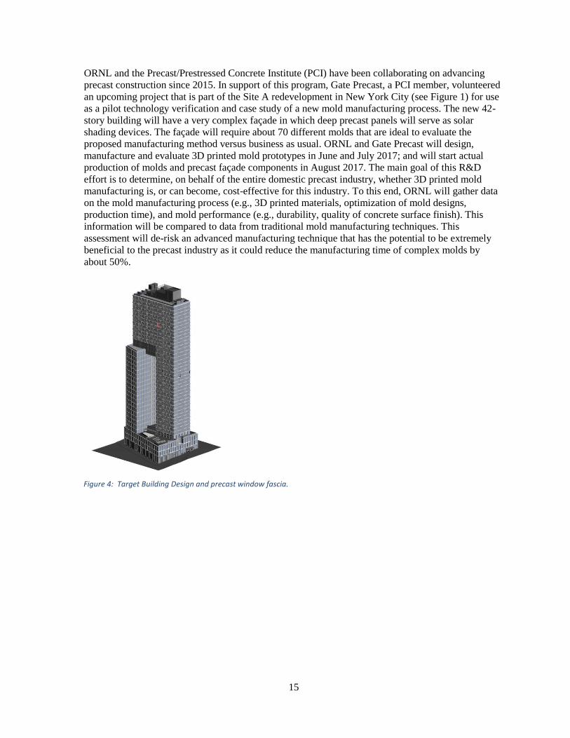
ORNL and the Precast/Prestressed Concrete Institute (PCI) have been collaborating on advancing
precast construction since 2015. In support of this program, Gate Precast, a PCI member, volunteered
an upcoming project that is part of the Site A redevelopment in New York City (see Figure 1) for use
as a pilot technology verification and case study of a new mold manufacturing process. The new 42-
story building will have a very complex façade in which deep precast panels will serve as solar
shading devices. The façade will require about 70 different molds that are ideal to evaluate the
proposed manufacturing method versus business as usual. ORNL and Gate Precast will design,
manufacture and evaluate 3D printed mold prototypes in June and July 2017; and will start actual
production of molds and precast façade components in August 2017. The main goal of this R&D
effort is to determine, on behalf of the entire domestic precast industry, whether 3D printed mold
manufacturing is, or can become, cost-effective for this industry. To this end, ORNL will gather data
on the mold manufacturing process (e.g., 3D printed materials, optimization of mold designs,
production time), and mold performance (e.g., durability, quality of concrete surface finish). This
information will be compared to data from traditional mold manufacturing techniques. This
assessment will de-risk an advanced manufacturing technique that has the potential to be extremely
beneficial to the precast industry as it could reduce the manufacturing time of complex molds by
about 50%.
Figure 4: Target Building Design and precast window fascia.
16
2. RESULTS AND DISCUSSION
The objective of phase 1 is to demonstrate the feasibility of either glass fiber reinforced ABS or carbon fiber reinforced ABS in molds that will be used to cast concrete. The goal is to identify which material has the best durability, lowest cost and what are the required design limitations (wall thicknesses). A prototype mold will be designed, fabricated and tested using two different materials. Gate Precast will manufacture test articles using both materials and visually inspect the molds for durability (wear). Phase 1 activities:
Task 1.1 – Mold design (ORNL/Gate Precast)
Task 1.2 – Mold manufacturing (ORNL)
Task 1.3 – Part testing (Gate Precast)
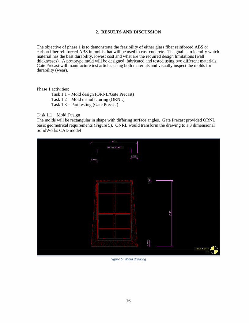
Task 1.1 – Mold Design
The molds will be rectangular in shape with differing surface angles. Gate Precast provided ORNL
basic geometrical requirements (Figure 5). ONRL would transform the drawing to a 3 dimensional
SolidWorks CAD model
Figure 5: Mold drawing
17
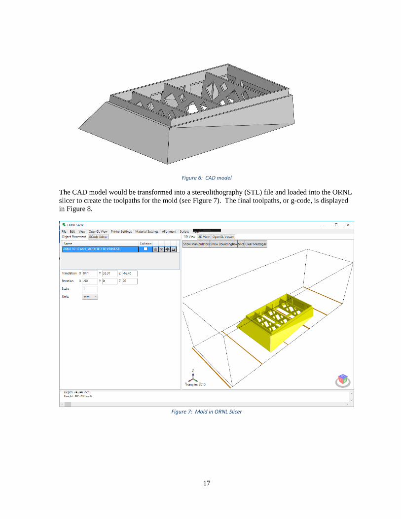
Figure 6: CAD model
The CAD model would be transformed into a stereolithography (STL) file and loaded into the ORNL
slicer to create the toolpaths for the mold (see Figure 7). The final toolpaths, or g-code, is displayed
in Figure 8.
Figure 7: Mold in ORNL Slicer
18
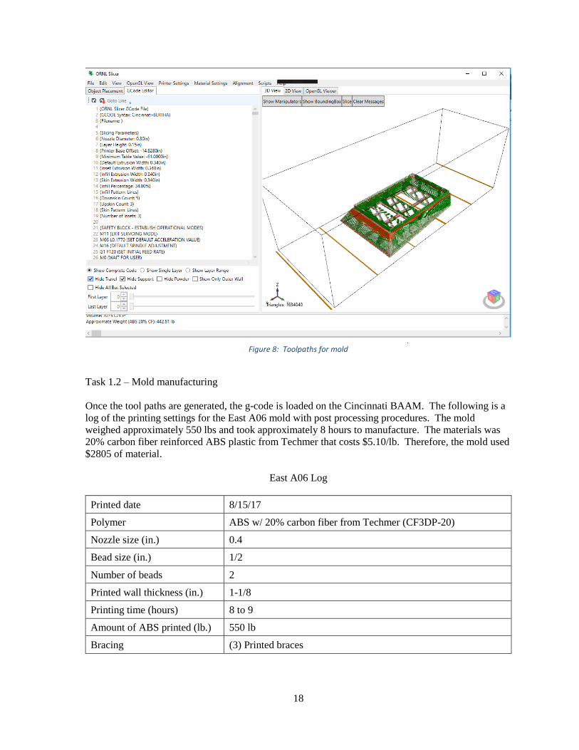
Figure 8: Toolpaths for mold
Task 1.2 – Mold manufacturing
Once the tool paths are generated, the g-code is loaded on the Cincinnati BAAM. The following is a
log of the printing settings for the East A06 mold with post processing procedures. The mold
weighed approximately 550 lbs and took approximately 8 hours to manufacture. The materials was
20% carbon fiber reinforced ABS plastic from Techmer that costs $5.10/lb. Therefore, the mold used
$2805 of material.
East A06 Log
Printed date 8/15/17
Polymer ABS w/ 20% carbon fiber from Techmer (CF3DP-20)
Nozzle size (in.) 0.4
Bead size (in.) 1/2
Number of beads 2
Printed wall thickness (in.) 1-1/8
Printing time (hours) 8 to 9
Amount of ABS printed (lb.) 550 lb
Bracing (3) Printed braces
19
Add-ons
(10) Gussets that reinforce the bottom flange: (2) top, (2) bottom,
(3) on each side. Some of these will be used as supporting pads
for vibrators.
Machined date 8/16/17 and /17/17
Machining process
1st pass 0.000 alignment verification
2nd pass 0.150 in. with 1-¼ inch diamond flake carbine insert face mill
3rd pass 0.050 in. with 1-¼ inch diamond flake carbine insert face mill
4th pass 320 grit sandpaper
Wall thickness 3/4”
Machining time
Setup (hours) 2 (moving from printer to router and calibration)
Machine top (hours) 8 hours
Flip mold (hours) 2
Machine bottom (hours) 3
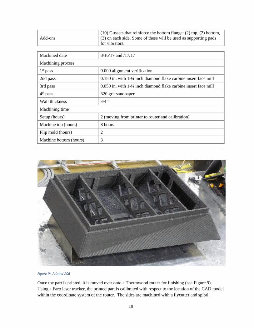
Figure 9: Printed A06
Once the part is printed, it is moved over onto a Thermwood router for finishing (see Figure 9).
Using a Faro laser tracker, the printed part is calibrated with respect to the location of the CAD model
within the coordinate system of the router. The sides are machined with a flycutter and spiral
20
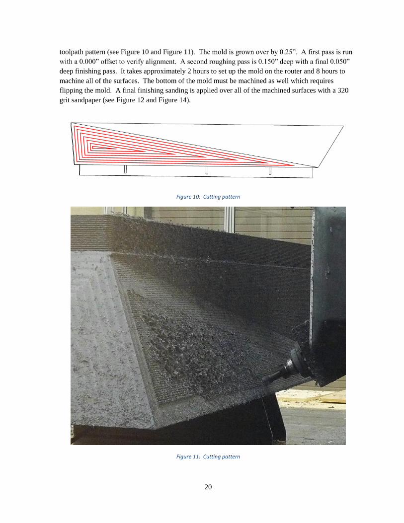
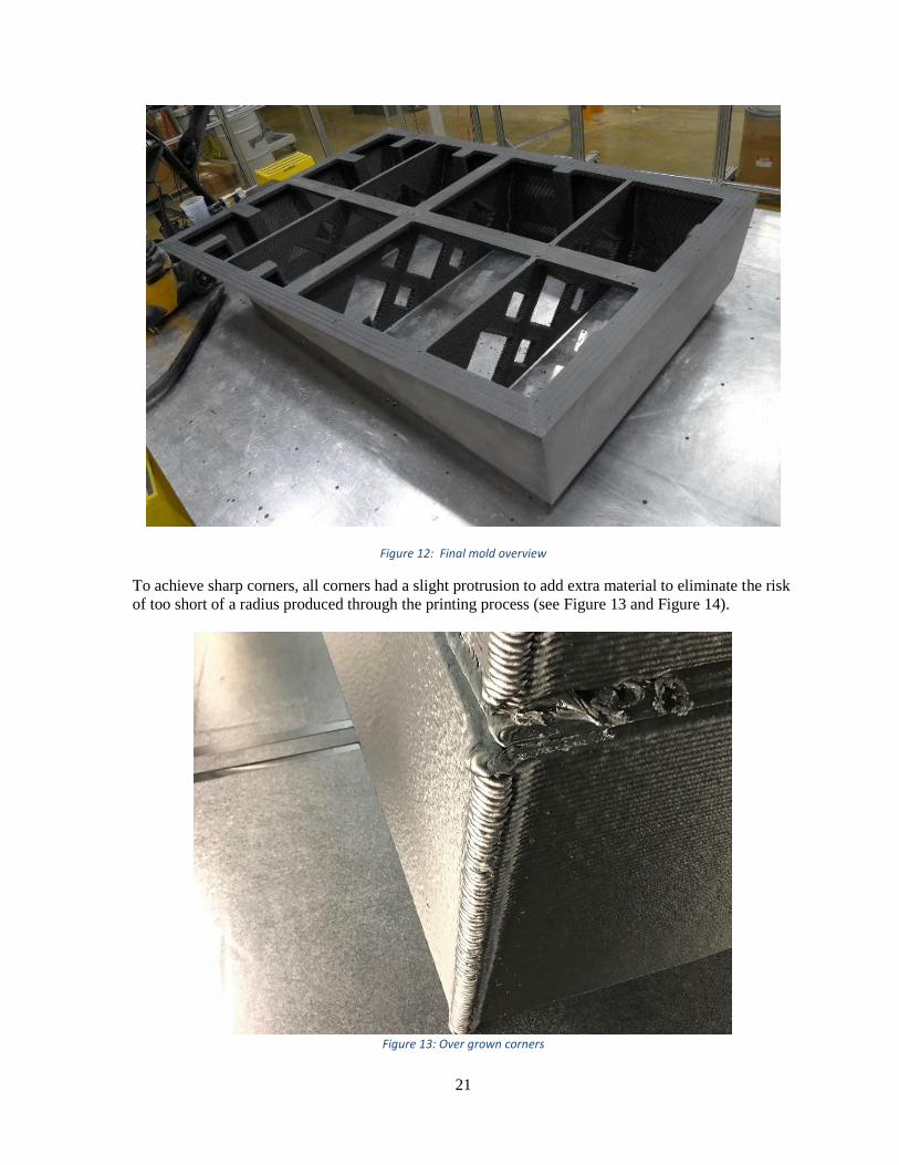
toolpath pattern (see Figure 10 and Figure 11). The mold is grown over by 0.25”. A first pass is run
with a 0.000” offset to verify alignment. A second roughing pass is 0.150” deep with a final 0.050”
deep finishing pass. It takes approximately 2 hours to set up the mold on the router and 8 hours to
machine all of the surfaces. The bottom of the mold must be machined as well which requires
flipping the mold. A final finishing sanding is applied over all of the machined surfaces with a 320
grit sandpaper (see Figure 12 and Figure 14).
Figure 10: Cutting pattern
Figure 11: Cutting pattern
21
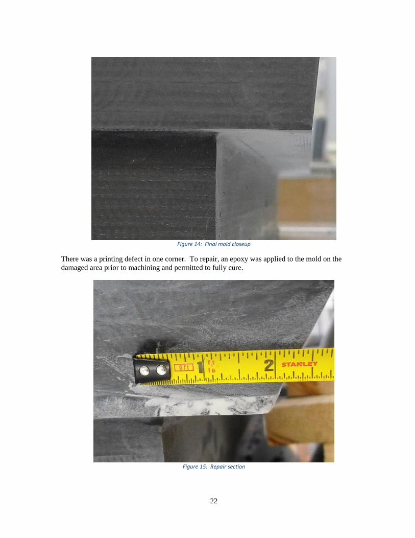
Figure 12: Final mold overview
To achieve sharp corners, all corners had a slight protrusion to add extra material to eliminate the risk
of too short of a radius produced through the printing process (see Figure 13 and Figure 14).
Figure 13: Over grown corners
22
Figure 14: Final mold closeup
There was a printing defect in one corner. To repair, an epoxy was applied to the mold on the
damaged area prior to machining and permitted to fully cure.
Figure 15: Repair section
23
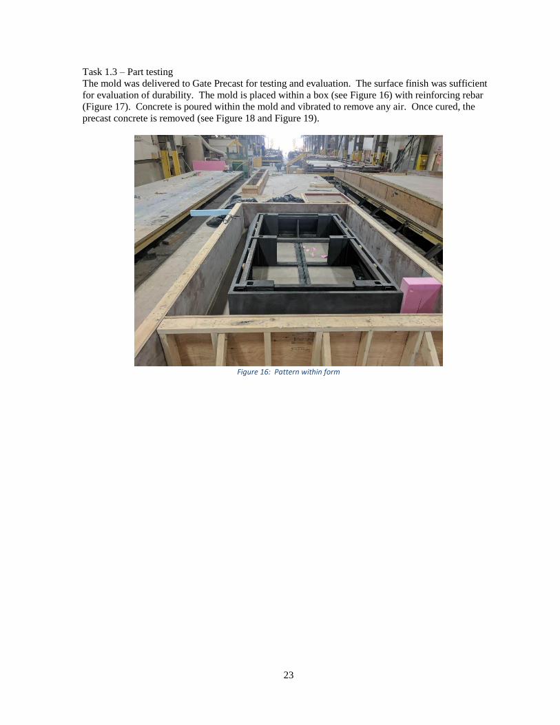
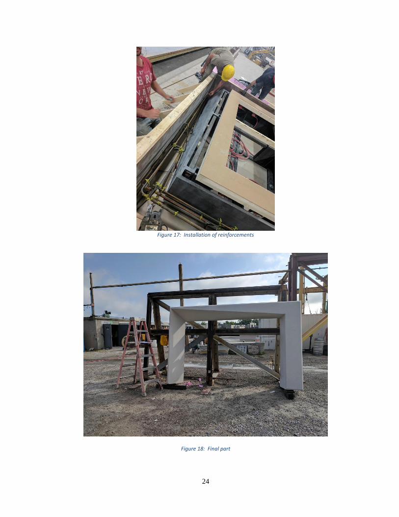
Task 1.3 – Part testing
The mold was delivered to Gate Precast for testing and evaluation. The surface finish was sufficient
for evaluation of durability. The mold is placed within a box (see Figure 16) with reinforcing rebar
(Figure 17). Concrete is poured within the mold and vibrated to remove any air. Once cured, the
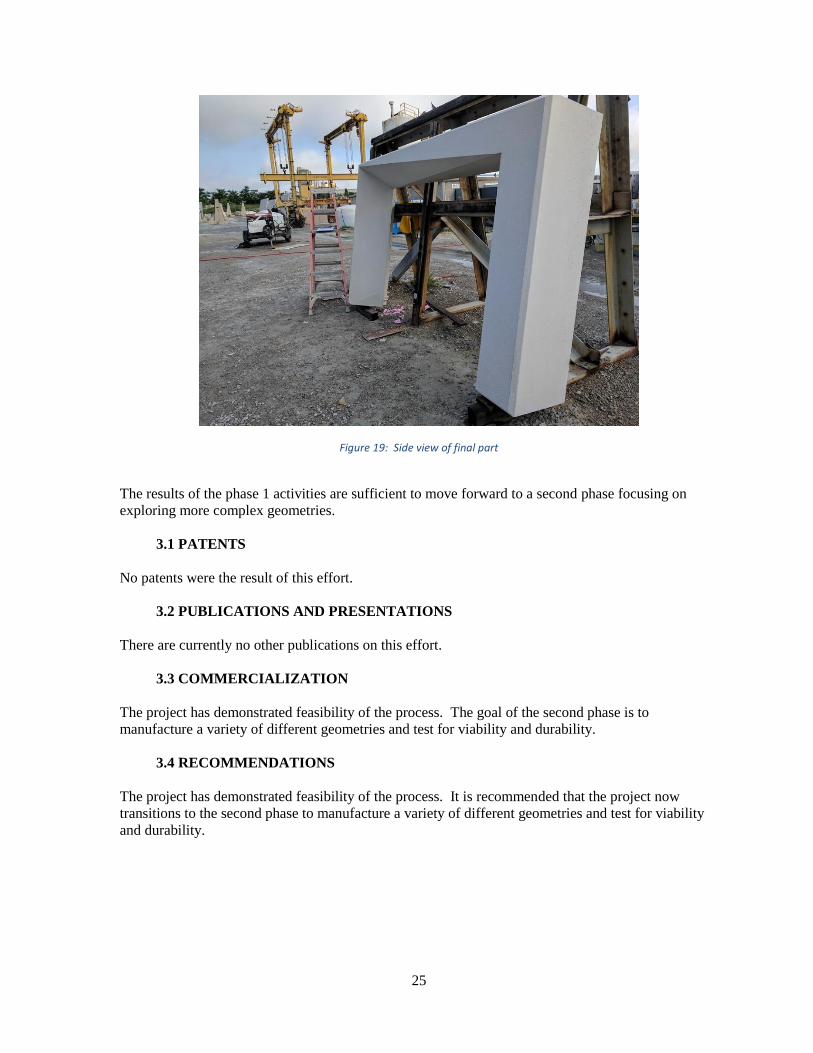
precast concrete is removed (see Figure 18 and Figure 19).
Figure 16: Pattern within form
24
Figure 17: Installation of reinforcements
Figure 18: Final part
25
Figure 19: Side view of final part
The results of the phase 1 activities are sufficient to move forward to a second phase focusing on
exploring more complex geometries.
3.1 PATENTS
No patents were the result of this effort.
3.2 PUBLICATIONS AND PRESENTATIONS
There are currently no other publications on this effort.
3.3 COMMERCIALIZATION
The project has demonstrated feasibility of the process. The goal of the second phase is to
manufacture a variety of different geometries and test for viability and durability.
3.4 RECOMMENDATIONS
The project has demonstrated feasibility of the process. It is recommended that the project now
transitions to the second phase to manufacture a variety of different geometries and test for viability
and durability.