Embed Size (px)
Citation preview
1
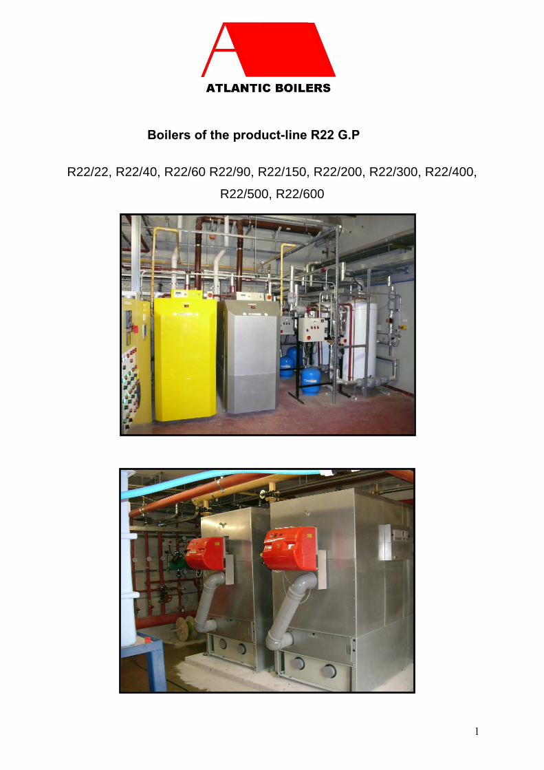
Boilers of the product-line R22 G.P
R22/22, R22/40, R22/60 R22/90, R22/150, R22/200, R22/300, R22/400,
R22/500, R22/600
4
The manufacturer of the R series is
RYLLTECH
Ryllstrasse 1
D-19348 Perleberg
+49-3876-791700
The sole distributor for the UK is
ATLANTIC 2000PO Box 11 Ashton Under Lyne OL6 7TR+44. (0) 161 621 5960 Fax +44. (0) 161 621 [email protected]
This manual is valid exclusively for the line of products R22The contained information cannot be transferred onto otherboiler types.
To be considered with this manual:
The manual for the controller
The manual for the burner
The installation manual
PO Box 11 Ashton Under Lyne OL6 7TR+44. (0) 161 621 5960 Fax +44. (0) 161 621 5966

5
77778
101112131616171718181919
2020212222222324242627292930303031323233343538394146
CONTENTS
1) GENERAL………………………………………………………………………………………….a) Purpose……………………………………………………………….……………b) Updating of this Manual …………………………………………..……………c) Declaration………………………………………………………………….…….
2) THE COMPONENTS OF THE R SERIES……………………….…………………………..3) MATERIALS OF CONSTRUCTION…………………………………………………………..4) CHARACTERISTICS OF THE R SERIES……………………………………………..……..5) INSTALLATION REQUIREMENTS……………….…………………………………………6) THE GAS PIPEWORK CONNECTIONS…………...…………………………………………7) THE OIL PIPE LINES……………………………………………………………….………...
a) Gravity fed…………………………………………………….…………………….b) Pumped system, 35 & 28 seconds oil…………………………..……………..c) Pumped system, B100 ………………….……...…………………………
8) R22 BOILER FUNCTIONS…………………………………………………..………………..a) The controller……………………………………………….…………………….b) Operation of the burner …………..……………………………..……………..c) Operation of the main heat exchanger……………...…………………………d) Operation of the condensing heat exchanger and the neutralisation ofoutgoing condensate……………………….…….…………………………………..e) Operation of the flue extract system…………………………………………..…
9) IMPORTANT NOTES……………………………………………………………….…………10) WHAT TO DO IN EVENT OF EMERGENCY……………………………………………..11) OPERATING INSTRUCTIONS…………………………………………………..…………..
a) Information to the owner / user…………………………………………………b) Preparation for start-up……………………….………………………………..c) Switching the boiler on…………………………..………….…………………..d) Switching the boiler off…………………………..…………………….………..
12) BOILERHOUSE SPACE REQUIREMENT…………………………………………..……13) SIZING OF FLUES & CHIMNEYS………………………………………………………...14) INSTALLATION MANUAL………………………………………………………………….
a) Delivery to site…………………………..………………………………..………b) Satisfactory delivery and damage incurred during transit…………….……..c) Adequate storage to site……………………………………………..……..……..d) Positioning and piping up……………………………….…………….…………e) Commissioning and preventive maintenance………………………..………..f) The boiler room………………………………..…………………………..……….g) Flue gas extract system……………………………………………..…………..h) Fresh air supply for combustion…………………………………………………i). Neutralization/condensate drain………………………………………………..j). Piping up……………………………………………………………………………k) Burner and fuel supply………………………..…………………..………………
15) MAINTENANCE………………………………………………………………………………16) COMMISSIONING……………………………………………………………………………17) THE GUARANTEE ON THE R SERIES18) SERVICING/FAULT FINDING CHART………………………..……………………… 47

6
Type designation plate R22 –90
*Pressures up to 8bars available
Atlantic BoilersPo Box 11Ashton Under LyneOL6 7TR
Tel: 0207 237 4912Fax: 0161 621 5966Email: [email protected]: www.atlanticboilers.com
*
7
1) GENERAL
a) Purpose
The RYLL 22 (R22) boilers generate heat in low-pressure hot water systems. The boilers use
either natural gas, propane or butane, or fuel oil, B100 biodiesel. No other fuels are
acceptable.
THE BURNER DETAILS SHOULD ALWAYS BE CHECKED.
b) Updating of this Manual
These operating instructions may be revised at a later stage.
At this stage, the instructions, technical norms and rules correspond to technical development
at this time. The right is reserved to change or improve these matters no automatic up-dating
of this Manual is provided, but commissioning and servicing facilities will be available on
request, at agreed terms.
c) Declaration
The R22 boiler represents “state of the art” technology as at this time and also the technical
description as given in this manual.
All instructions for installation are based on European Union rules & regulations.
The R22 boilers are tested as follows:
I ) inspection of bought-in components
II ) pressure test of main heat exchanger from 5 to 12Bars
depending on requirement
III ) witnessed checklist of assembly process
IV ) final assembly check
V ) pre-set and record of all working parameters
PO Box 11 Ashton Under Lyne OL6 7TR+44. (0) 161 621 5960 Fax +44. (0) 161 621 5966
8
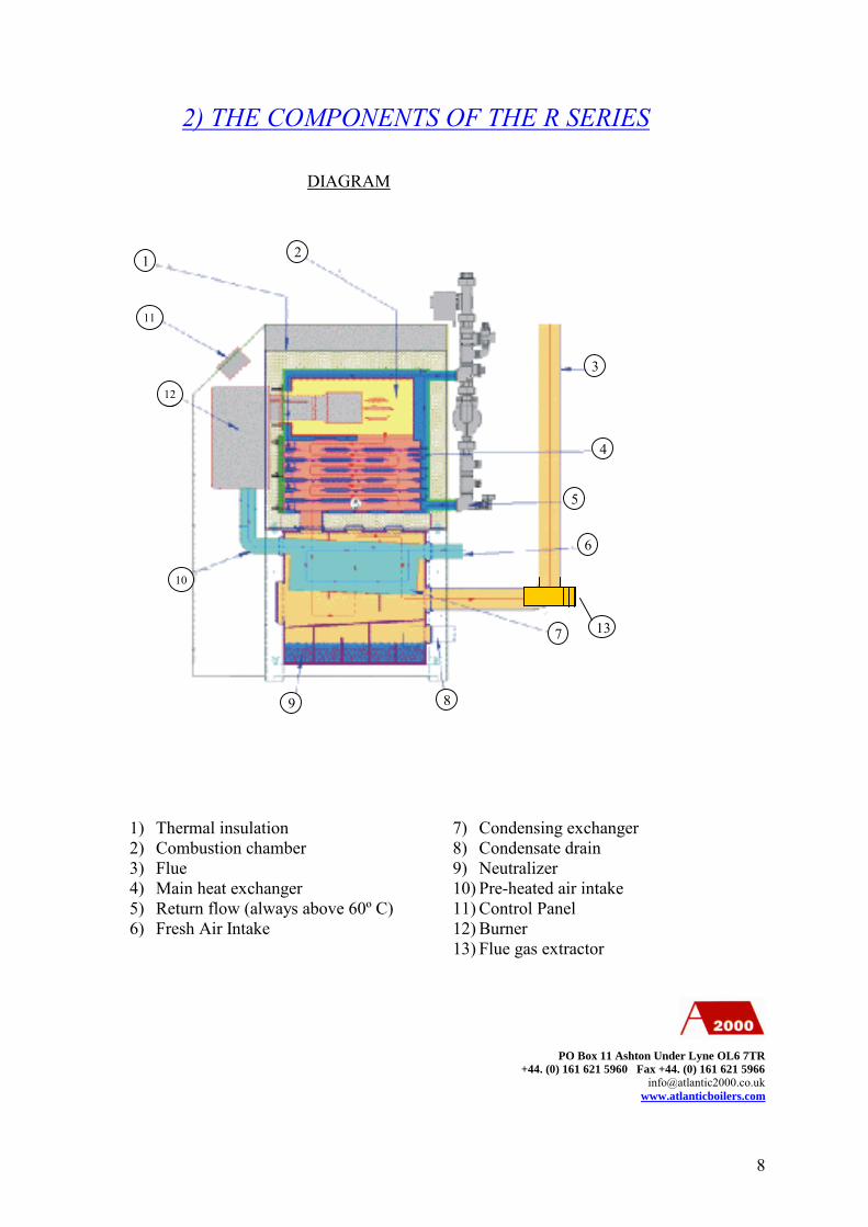
2) THE COMPONENTS OF THE R SERIES
PO Box 11 Ashton Under Lyne OL6 7TR+44. (0) 161 621 5960 Fax +44. (0) 161 621 5966
1) Thermal insulation2) Combustion chamber3) Flue4) Main heat exchanger5) Return flow (always above 60º C)6) Fresh Air Intake
7) Condensing exchanger8) Condensate drain9) Neutralizer10) Pre-heated air intake11) Control Panel12) Burner13) Flue gas extractor
3
4
21
5
6
8
7
9
10
5
511
12
DIAGRAM
13

9
ISOMETRIC VIEW
PO Box 11 Ashton Under Lyne OL6 7TR+44. (0) 161 621 5960 Fax +44. (0) 161 621 5966
1) Control Panel2) 4 way valve3) Constant temperature circuit flow
and return4) Shunt pump5) Return flow (always above 60º C)
6) Flue gas extractor7) Condensing exchanger8) Fresh air burner intake9) Burner10) Control Panel
1
4
3
2
7
8
9
6
5

10
3) MATERIALS OF CONSTRUCTION
WARNING: Certain parts of the boiler are permanently electrically charged and are
dangerous if touched or revealed. It is essential that the safety instructions are observed. Lack
of attention can lead to damage to property, injury or even death.
Main heat exchangerBase FrameCladdingCondensing heat exchangerFlue gas extract systemThermal insulation rock wool (DIN 4102-A2)Flue gas extract fan rotor PVDF polyvinyldenefluorid
Steel
PP Propylene

11
4) CHARACTERISTICS OF THE R SERIES
PERFORMANCEModel 17 22 40 60 90 150 200 300 400 500 600
Maximum Output kW 17 22 40 60 90 150 210 315 370 485 605
Standard Minimum Output kW 10 15 12 20 33 40 42 80 80 80 150
Full load efficiencyAmbient air 20 degC Oil %gcv 93.7 95.2 95.5 94.8 89.2 96.8 90.0 95.5 88.5 92.0 95.5
Gas %gcv 95 96.5 96.8 96.1 90.5 98.1 91.2 96.8 89.7 93.2 96.8
Fuel used Oil Litres Hr 1.7 2.2 4.0 7.2 9.1 14.9 26.0 31.0 45.7 52.6 69.5
Gas m3 Hr 1.7 2.0 4.0 6.0 9.6 15.0 19.8 30.0 46.3 53.1 63.5
Exit Flue gases@30ºC Oil m³/hr 23 30 55 82 124 206 274 411 547 684 893
Gas m³/hr 25 34 61 92 138 230 306 460 613 767 920
Dry weight kg 125 200 300 438 794 996 1014 1790 1975 2100 2225
Water contents ltrs 36 36 75 80 197 330 500 910 1010 1110 1475
Min water pressure BARS 0.5 0.5 0.5 0.5 0.5 0.5 0.5 0.5 0.5 0.5 0.5
Standard water pressure BARS 3.0 3.0 3.0 3.0 3.0 3.0 3.0 3.0 3.0 3.0 3.0
Max (on order) BARS 7.0 7.0 7.0 7.0 7.0 7.0 7.0 7.0 7.0 7.0 7.0
DIMENSIONS mmModel 15 22 40 60 90 150 200 300 400 500 600
Height 1165 1365 1510 1645 1740 1945 1985 2070 2220 2220 2550
Width 350 445 545 550 740 885 1225 1225 1425 1425 1425
Depth 940 1000 1220 1330 1750 2030 3140 3770 3770 3770 3770
Height-demountable 600 750 895 985 965 1070 1281 1370 1400 1400 1510
Width-demountable 410 445 545 550 740 885 1225 1225 1225 1225 1225
Depth-demountable 645 680 760 784 1130 1255 1340 1970 1970 1970 1970
Access front 500 500 500 700 1000 1000 1000 1000 1000 1000 1000
Access one side 100 100 100 100 100 100 100 100 100 100 100
Access other side 500 500 500 500 500 500 500 500 500 500 500
Access rear 300 300 300 300 300 300 300 300 300 300 300
Access top 300 300 300 300 300 300 500 500 500 500 500
CONNECTIONS mmModel 15 22 40 60 90 150 200 300 400 500 600
Fresh air inlet 75 75 75 75 110 110 125 125 150 150 200
Warm air burner inlet 50 50 50 70 100 100 125 125 150 150 200
Fresh gas outlet 75 75 75 75 110 125 200 200 200 200 200
Heating flow 25 25 25 25 40 50 65 65 80 80 100
Heating return 25 25 25 25 40 50 65 65 80 80 100
Hot water primaries 25 25 25 25 32 40 50 50 50 50 50Condensate 50 50 50 50 50 50 50 50 50 50 50
12
5) INSTALLATION REQUIREMENTS
( I ) ambient temperature of boiler room not to fall below 0 °C or rise above 40 °C
( II ) boiler room to be dry and dust-free and clear of chemical influence
( III ) boiler base must be flat, resistant to fire and strong enough to carry the boiler
weight
( IV) good access to front and rear are required for maintenance
( V ) a suitable electric supply is needed
( VI ) the condensate from the boiler has been neutralised before entering the public waste
system
( VII ) an adequate water supply is required
( VIII ) for a gas burner, there must be a matching gas supply
( IX ) the gas installation must meet all appropriate regulations
( X ) the gas flues must be manufactured and installed to appropriate
regulations
( XI ) the flue gases extract system must be constructed and installed to
appropriate condensing flue regulations
( XII) for an oil burner, appropriate regulations and recommendations must be followed.
PO Box 11 Ashton Under Lyne OL6 7TR+44. (0) 161 621 5960 Fax +44. (0) 161 621 5966
13
3 6 9 12 15 20 25 30 40 5020 9.7 6.625 18 12 10 8.5 7.532 39 27 21 18 16 14 12 11 9.2 8.140 59 40 32 27 24 21 18 16 14 1250 110 76 61 52 46 39 34 31 26 2365 220 150 120 100 92 79 70 63 54 4780 340 230 190 160 140 120 110 97 83 73100 690 470 380 330 290 250 220 200 170 150
Length of pipe (metres)
Nominalsize (mm)
Discharge (m³/h)
10 20 30 40 50 60 70 80 90 100 125 1503/4 340 2301 640 440 3501¼ 1400 930 740 630 560 500 460 430 400 3801½ 2100 1400 1100 960 850 760 700 650 610 570 510 4602 3900 2600 2100 1800 1600 1400 1300 1200 1100 1000 960 8602½ 7700 5300 4300 3600 3200 2900 2700 2500 2300 2200 1900 18003 12000 8200 6600 5600 5000 4500 4100 3800 3600 3400 3000 27004 24000 1700 1300 11000 10000 9200 8400 7800 7300 6900 6100 5500
Discharge (FT³/h) Length of pipe (feet)
Nominalsize (ins)
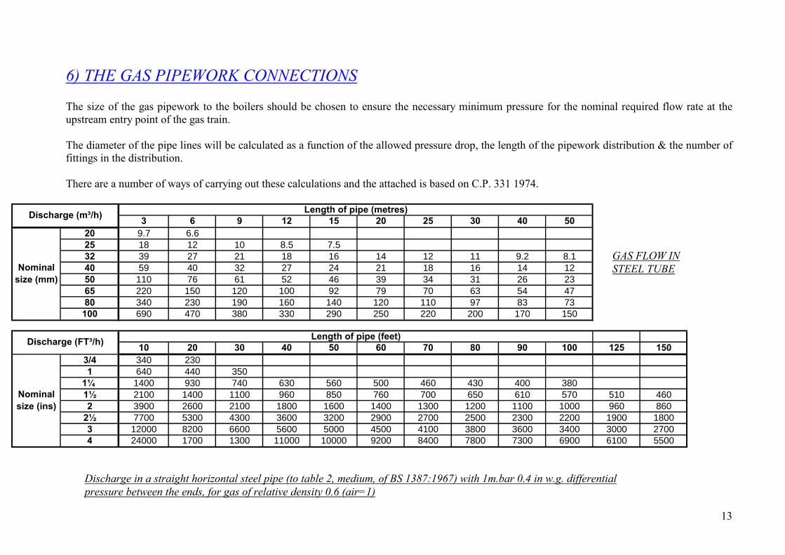
6) THE GAS PIPEWORK CONNECTIONS
The size of the gas pipework to the boilers should be chosen to ensure the necessary minimum pressure for the nominal required flow rate at theupstream entry point of the gas train.
The diameter of the pipe lines will be calculated as a function of the allowed pressure drop, the length of the pipework distribution & the number offittings in the distribution.
There are a number of ways of carrying out these calculations and the attached is based on C.P. 331 1974.
Discharge in a straight horizontal steel pipe (to table 2, medium, of BS 1387:1967) with 1m.bar 0.4 in w.g. differentialpressure between the ends, for gas of relative density 0.6 (air=1)
GAS FLOW INSTEEL TUBE

14
3 6 9 12 15 20 25 30 40 5022 8.7 5.828 18 12 9.4 8 7 5.935 32 22 17 15 13 11 9.5 8.5 7.2 6.342 54 37 29 25 22 18 16 15 12 1154 110 75 60 51 45 38 33 30 26 2376 280 190 150 130 120 98 86 78 66 58108 750 510 410 350 310 260 230 210 180 160
Nominalsize (mm)
Discharge (m³/h) Length of pipe (metres)
10 20 30 40 50 60 70 80 90 100 125 1503/4 630 420 3401 1100 740 580 500 440 390 3601¼ 1800 1200 950 810 710 640 590 540 510 480 420 3801½ 3900 2600 2100 1800 1600 1400 1300 1200 1100 1000 930 8302 7000 4800 3800 3200 2800 2600 2300 2200 2000 1900 1700 15002½ 11000 7700 6200 5200 4600 4200 3800 3500 3300 3100 2800 25003 17000 12000 9400 8000 7100 6400 5800 5400 5100 4800 4200 38004 25000 17000 13000 11000 10000 9100 8400 7800 7300 6900 6100 5500
Discharge (FT³/h) Length of pipe (feet)
Nominalsize (ins)
PO Box 11 Ashton Under Lyne OL6 7TR+44. (0) 161 621 5960 Fax +44. (0) 161 621 5966
Discharge in a straight horizontal copper tube (to table of BS 659:1967) with 1m.bar 0.4 in w.g. differential pressurebetween the ends, for gas of relative density 0.6 (air=1)
GAS FLOW INCOPPER TUBE
15
Mild Steel Copper Elbows Tees 90º Bendsup to 25 up to 28 0.5 0.5 0.3
32 top 40 35 to 42 1 1 0.3
50 54 1.5 1.5 0.5
80 76.1 2.5 2.5 1
Nominal size (mm) Appropriate additional lenghtsto be allowed (m)
Mild Steel Copper Elbows Tees 90º Bendsup to 1 up to 1 2 2 1
1 ¼ to 1 ½ 1 ¼ to 1 ½ 3 3 1
2 2 5 5 2
3 3 8 8 3
Nominal size (ins) Appropriate additional lenghtsto be allowed (ft)
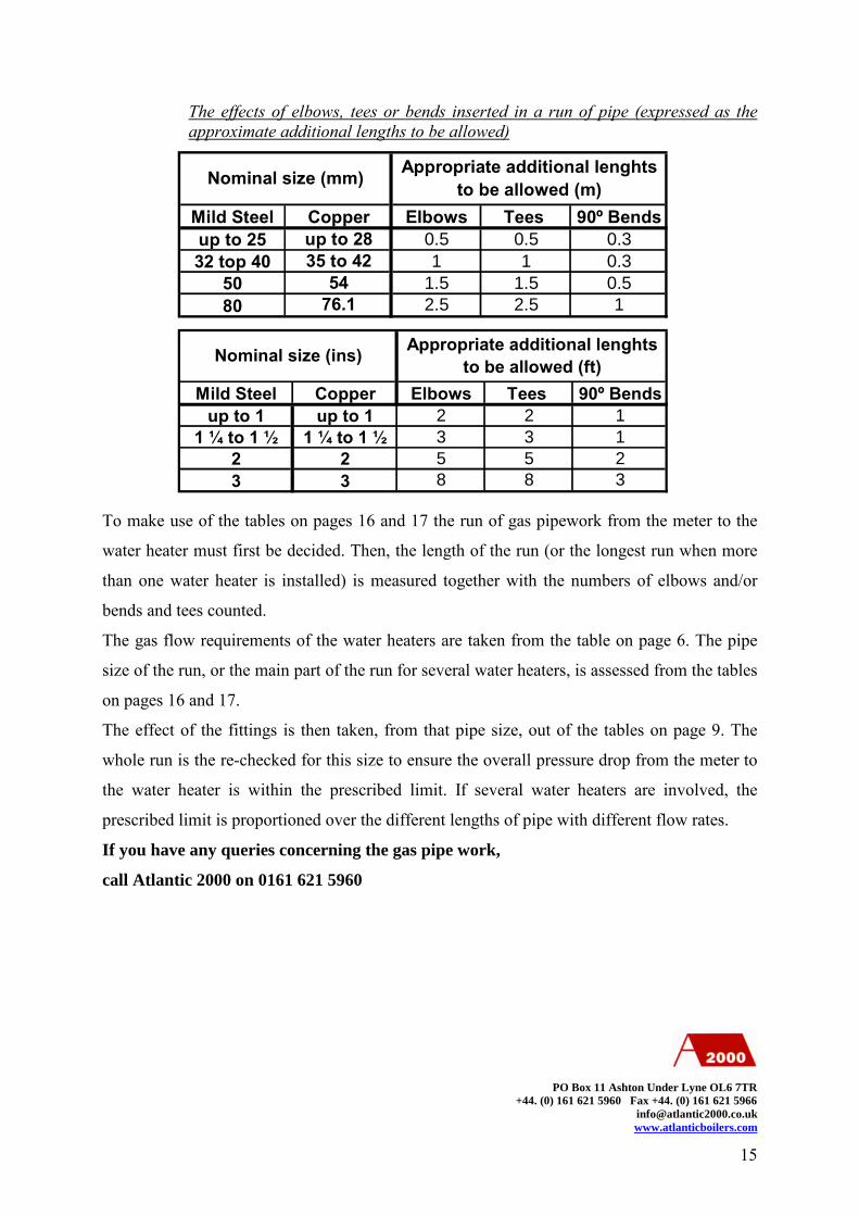
The effects of elbows, tees or bends inserted in a run of pipe (expressed as theapproximate additional lengths to be allowed)
To make use of the tables on pages 16 and 17 the run of gas pipework from the meter to the
water heater must first be decided. Then, the length of the run (or the longest run when more
than one water heater is installed) is measured together with the numbers of elbows and/or
bends and tees counted.
The gas flow requirements of the water heaters are taken from the table on page 6. The pipe
size of the run, or the main part of the run for several water heaters, is assessed from the tables
on pages 16 and 17.
The effect of the fittings is then taken, from that pipe size, out of the tables on page 9. The
whole run is the re-checked for this size to ensure the overall pressure drop from the meter to
the water heater is within the prescribed limit. If several water heaters are involved, the
prescribed limit is proportioned over the different lengths of pipe with different flow rates.
If you have any queries concerning the gas pipe work,
call Atlantic 2000 on 0161 621 5960
PO Box 11 Ashton Under Lyne OL6 7TR+44. (0) 161 621 5960 Fax +44. (0) 161 621 5966
16
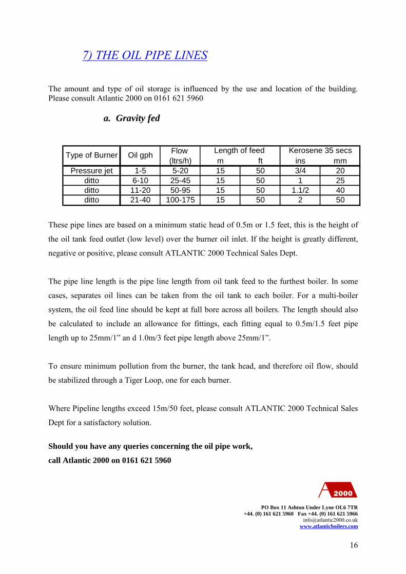
7) THE OIL PIPE LINES
The amount and type of oil storage is influenced by the use and location of the building.Please consult Atlantic 2000 on 0161 621 5960
a. Gravity fed
These pipe lines are based on a minimum static head of 0.5m or 1.5 feet, this is the height of
the oil tank feed outlet (low level) over the burner oil inlet. If the height is greatly different,
negative or positive, please consult ATLANTIC 2000 Technical Sales Dept.
The pipe line length is the pipe line length from oil tank feed to the furthest boiler. In some
cases, separates oil lines can be taken from the oil tank to each boiler. For a multi-boiler
system, the oil feed line should be kept at full bore across all boilers. The length should also
be calculated to include an allowance for fittings, each fitting equal to 0.5m/1.5 feet pipe
length up to 25mm/1” an d 1.0m/3 feet pipe length above 25mm/1”.
To ensure minimum pollution from the burner, the tank head, and therefore oil flow, should
be stabilized through a Tiger Loop, one for each burner.
Where Pipeline lengths exceed 15m/50 feet, please consult ATLANTIC 2000 Technical Sales
Dept for a satisfactory solution.
Should you have any queries concerning the oil pipe work,
call Atlantic 2000 on 0161 621 5960
PO Box 11 Ashton Under Lyne OL6 7TR+44. (0) 161 621 5960 Fax +44. (0) 161 621 5966
Flow
(ltrs/h) m ft ins mmPressure jet 1-5 5-20 15 50 3/4 20
ditto 6-10 25-45 15 50 1 25ditto 11-20 50-95 15 50 1.1/2 40ditto 21-40 100-175 15 50 2 50
Length of feed Kerosene 35 secsType of Burner Oil gph

17
b. Pumped system, 35 & 28 seconds oil
The table gives general guidance, please consult Atlantic 2000 on 0161 621 5960
c. Pumped system, B100
Please note that with rapeseed oil the oil line needs to be traced-heated and that the
storage tank requires an immersion heater in order to maintain the rapeseed oil temperature
around 8ºC
The table gives general guidance, please consult Atlantic 2000 on 0161 621 5960
PO Box 11 Ashton Under Lyne OL6 7TR+44. (0) 161 621 5960 Fax +44. (0) 161 621 5966
7.5 15 22.5 30 40 45 55 60 75 9045 1½ 1½ 1½ 1½ 1½ 1½ 2 2 2½ 2½
180 1½ 1½ 1½ 2 2 2½ 2½ 2½ 2½ 3
320 1½ 2 2 2 2 2½ 2½ 2½ 3 3
450 2 2 2 2½ 2½ 3 3 3 3 3
590 2 2 2½ 2½ 2½ 3 3 3 3 4
Length of run, m
Pumping
rate
l/h
7.5 15 22.5 30 40 45 55 60 75 9045 ½ ½ ½ ½ ½ ½ ½ ¾ ¾ 1
180 ½ ½ ½ ½ ½ ¾ ¾ ¾ ¾ 1
320 ½ ½ ¾ ¾ ¾ ¾ ¾ 1 1 1
450 ½ ¾ ¾ ¾ ¾ 1 1 1 1 3
590 ½ ¾ ¾ 1 1 1 1 1 1¼ 1¼
Length of run, m
Pumping
rate
l/h
Tank size l 2500 5000 10000Approximate Immersion heater size kw 3 7.5 15
Special requirements apply; please contact Atlantic 2000 for technical details
18
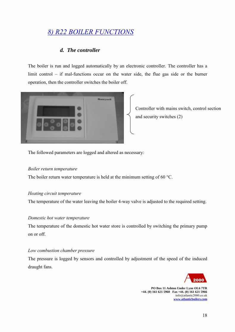
8) R22 BOILER FUNCTIONS
d. The controller
The boiler is run and logged automatically by an electronic controller. The controller has a
limit control – if mal-functions occur on the water side, the flue gas side or the burner
operation, then the controller switches the boiler off.
The followed parameters are logged and altered as necessary:
Boiler return temperature
The boiler return water temperature is held at the minimum setting of 60 °C.
Heating circuit temperature
The temperature of the water leaving the boiler 4-way valve is adjusted to the required setting.
Domestic hot water temperature
The temperature of the domestic hot water store is controlled by switching the primary pump
on or off.
Low combustion chamber pressure
The pressure is logged by sensors and controlled by adjustment of the speed of the induced
draught fans.
PO Box 11 Ashton Under Lyne OL6 7TR+44. (0) 161 621 5960 Fax +44. (0) 161 621 5966
Controller with mains switch, control section
and security switches (2)
19
The combustion chamber pressure sensor must be firmly connected to the burner nipple and
care taken to ensure that there is no leakage.
Weather compensated control
The external temperature is logged by sensor and corresponding adjustments made to the flow
temperature of the space heating circuit.
b) Operation of the burner
The burner is very reliable, has low consumption and emits little pollution. See the attached
manual
The oil burner is marked “P”, the gas burner “G”.
The burner is pre-set to the designated output at the factory, and should not be adjusted on
site.
c) Operation of the main heat exchanger
The design of the components of the main heat exchanger allows maximum heat exchange to
the low-pressure hot water. To prevent over-heating or excessive pressure, four safety limits
are in place:
I ) boiler temperature limit sensor at 100 °C
II ) flue gas temperature limit sensor at 95 °C (transition from main heat exchanger to
condensing heat exchanger)
III ) safety valve (normally at 3BARS)
IV ) boiler flow temperature sensor
WARNING: NONE OF THESE CUT OUTS SHOULD BE SHORT CIRCUITED
PO Box 11 Ashton Under Lyne OL6 7TR+44. (0) 161 621 5960 Fax +44. (0) 161 621 5966

20
d) Operation of the condensing heat exchanger and the
neutralisation of outgoing condensate
The flue gases leave the main heat exchanger around 70°C and always below 90°C, then enter
the condensing heat exchanger. Much of the sensible and latent heat is then transferred to the
incoming fresh air. The pre-heated air is passed on to the burner ready for ultra high
efficiency combustion. As the flue gases are cooled to below condensing point, condensate is
formed which is then neutralized by granules of limestone and marble, before being flushed
into the waste water system.
e) Operation of the flue extract system
The exhaust system creates a negative pressure that draws
air into the boiler for combustion and, then, assists
combustion followed by consistent flue gas extract from the
boiler.
The system purges the boiler system before firing.
After switching off the burner, the system continues for a
pre- selected time in order to purge the boiler system further.
PO Box 11 Ashton Under Lyne OL6 7TR+44. (0) 161 621 5960 Fax +44. (0) 161 621 5966
The flue extract fan
View from the from the rear of the Condensing
Heat Exchanger
Combustion air intake
Flue gases outlet and combustion air intake
(balanced flue only)
condensate drain : 2 positions : run / service must
be set to run during normal operation
21
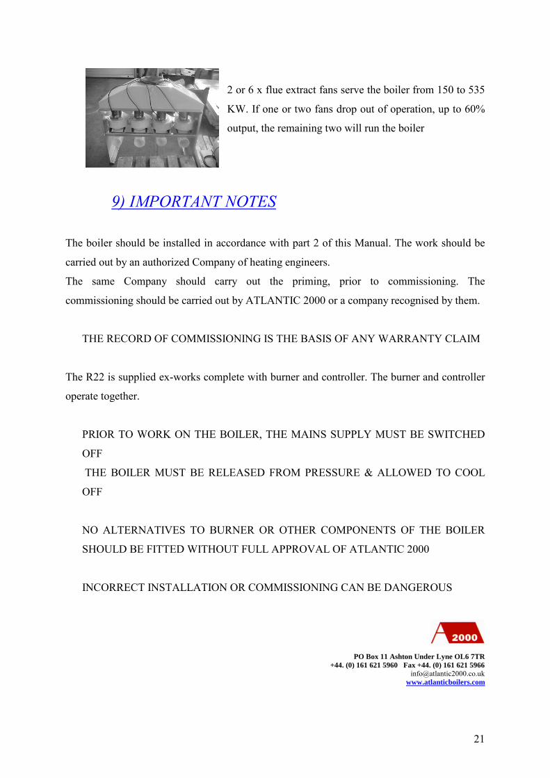
2 or 6 x flue extract fans serve the boiler from 150 to 535
KW. If one or two fans drop out of operation, up to 60%
output, the remaining two will run the boiler
9) IMPORTANT NOTES
The boiler should be installed in accordance with part 2 of this Manual. The work should be
carried out by an authorized Company of heating engineers.
The same Company should carry out the priming, prior to commissioning. The
commissioning should be carried out by ATLANTIC 2000 or a company recognised by them.
THE RECORD OF COMMISSIONING IS THE BASIS OF ANY WARRANTY CLAIM
The R22 is supplied ex-works complete with burner and controller. The burner and controller
operate together.
PRIOR TO WORK ON THE BOILER, THE MAINS SUPPLY MUST BE SWITCHED
OFF
THE BOILER MUST BE RELEASED FROM PRESSURE & ALLOWED TO COOL
OFF
NO ALTERNATIVES TO BURNER OR OTHER COMPONENTS OF THE BOILER
SHOULD BE FITTED WITHOUT FULL APPROVAL OF ATLANTIC 2000
INCORRECT INSTALLATION OR COMMISSIONING CAN BE DANGEROUS
PO Box 11 Ashton Under Lyne OL6 7TR+44. (0) 161 621 5960 Fax +44. (0) 161 621 5966
22
ALL LABELS WARNING OF DANGER MUST BE OBSERVED:
IGNORING DANGER WARNINGS MAY CAUSE INJURIES TO PERSONS AND
DAMAGE TO PROPERTY:
ATLANTIC 2000 EXCLUDES ANY LIABILITY FOR INJURY OR DAMAGE AS A
RESULT OF INCORRECT INSTALLATION OR OPERATION
10) WHAT TO DO IN EVENT OF EMERGENCY
-Switch off the main electricity supply.
-Close valves on oil or gas fuel supplies.
-In the event of fire, make use of powder-type extinguisher or buckets of sand.
-Then remove power fuses; close all fuel supplies, remove burner.
11) OPERATING INSTRUCTIONSa) Information to the owner / user
-Read this section carefully before making any change in the settings.
-Check with your installer on basic procedures
-Be familiar with the boiler operation.
For any questions or problems contact:
ATLANTIC 2000
Box 11, Ashton under Lyne
Lancashire OL6 7TR
Tel : 0161-621.5960
Fax : 0161-621.5966
E-mail : [email protected]
PO Box 11 Ashton Under Lyne OL6 7TR+44. (0) 161 621 5960 Fax +44. (0) 161 621 5966

23
For any servicing requirement contact:
ACM ATLANTIC
Tel : 0161-621.5964 or 0161-330.5631
For any spare part requirement contact:
ATLANTIC 4422
Tel : 0161-621.5962 or 0161-330.4422
FOR ANY ABNORMAL OPERATING NOISES
ANY UNTOWARD VIBRATION
ANY ELECTRICAL PROBLEMS
ANY PROBLEMS OF FUEL SUPPLY
From any boiler, burner, pump or fan
SWITCH THE BOILER IMMEDIATELY TO “OFF”
All malfunctions should be tackled by qualified technicians
WARNING :Only restart the boiler after all faults are repaired.
b) Preparation for start-up
Check before
-All connections: Fuel supply, water, exhausts system, low pressure, sensors (Heating
circuit sensor(s), outside temp. sensor, return sensor)
-All heating system valves are open
-The heating system is full of water and the system pressure is correct
-The neutralization tank is filled with water and the condensate outlet is set to the
work – position (turn to the extreme left), the water level in the neutralization tank
must reach up to the condensate drain
-The fuel Oil/ Gas supply is connected and the valves are open
24
-The fuel pipe (oil) and the filter are free of trapped air bubbles
- Check and open up all heating system valves.
- Check the fuel supply against burner model
- Check that the heating system is full of water (Do not top-up the boiler if hot)
With fuel oil, always turn off the boiler during the period required to re-fill the storage tank,
and for a further period of 30 minutes thereafter
Then, set the boiler into operation, checking for any failures
c) Switching the boiler on
-Switch on the main supply
-Turn on the Controller at the main switch
-The boiler controller will carry out a diagnostic procedure to start
-The flue extract fan will start to build up the low-pressure setting,
- With an oil burner the burner will start preparing up the Oil, and start thereafter
- With gas burner the burner will start immediately
If problems re-occur, switch off the system via the controller to avoid any damage. Note
the message on the display and inform your servicing engineer. Do not undertake repairs
without advice or help from your servicing engineer.
e. Switching the boiler off
To turn off the boiler (for oil filling etc): -wait until the controller first turns off the burner
-then turns off the flue extract fan
-then turn off the main switch manually
Works on the boiler may only be carried out if
-The mains is switched off
-The boiler is pressure-free and has cooled down.
Any conversion without explicit permission of ATLANTIC 2000 are prohibited.

25
The boiler is to be serviced by a specialist one time in the year.
Here, it is to be respected especially to density of the combustible lead, of the supply air pipe
and of the exhaust. Defect parts must be replaced exclusively by guaranteed parts from
ATLANTIC 4422.

26
12) BOILER HOUSE SPACE REQUIREMENTAll boilers can be placed directly onto hard level ground. No boiler plinth is required as the high grade
plastic condenser is located on the low part of the boiler.
The noise level emanating from the boilers is below 72 dBA. In a normal boilerhouse with masonry or
concrete walls of minimum 6’’ thickness, there will be little significant noise passing to surrounding
structure. However, if the boiler is located close to sleeping quarters or other areas requiring especially
low noise levels, an acoustic shroud can be added and will take the noise level down below 62 dBA. Also,
consideration should be given to the acoustic behavior of the boilerhouse with special attention to the
ventilation arrangements and the base of the boiler. In these cases information can be provided to assist in
the design.
The two drawings above show the minimum dimensions recommended for one boiler for existing
installations. These dimensions can be reduced even further, but the hatched areas shown are essential for
maintenance.
The side access should be 500mm on one side and 100mm on the other side, no matter which side has the
largest access.
The top access should not be under 300mm.
On a cascade the spacing between each boiler can be reduced to 100mm, but one 500mm spacing is
required on one side of the cascade.
Modification can be done for special project, for further information contact:
ATLANTIC 2000
0161 621 5960
500
300
1000
500
Side elevation
500500
100 100
Front elevation
27
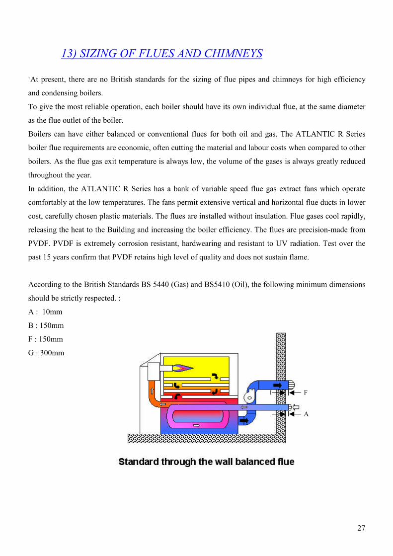
13) SIZING OF FLUES AND CHIMNEYS
`At present, there are no British standards for the sizing of flue pipes and chimneys for high efficiency
and condensing boilers.
To give the most reliable operation, each boiler should have its own individual flue, at the same diameter
as the flue outlet of the boiler.
Boilers can have either balanced or conventional flues for both oil and gas. The ATLANTIC R Series
boiler flue requirements are economic, often cutting the material and labour costs when compared to other
boilers. As the flue gas exit temperature is always low, the volume of the gases is always greatly reduced
throughout the year.
In addition, the ATLANTIC R Series has a bank of variable speed flue gas extract fans which operate
comfortably at the low temperatures. The fans permit extensive vertical and horizontal flue ducts in lower
cost, carefully chosen plastic materials. The flues are installed without insulation. Flue gases cool rapidly,
releasing the heat to the Building and increasing the boiler efficiency. The flues are precision-made from
PVDF. PVDF is extremely corrosion resistant, hardwearing and resistant to UV radiation. Test over the
past 15 years confirm that PVDF retains high level of quality and does not sustain flame.
According to the British Standards BS 5440 (Gas) and BS5410 (Oil), the following minimum dimensions
should be strictly respected. :
A : 10mm
B : 150mm
F : 150mm
G : 300mm
A
F

28
A
F
G B
Flue diameterMaximum
length of run(total)*
DN mR22/22 80 70 3R22/40 80 45 3R22/90 110 25 3R22/150 125 25 3R22/300 200 25 3R22/400 200 40 3R22/500 200 15 3
R22/600 250 40 3
Model Number ofbends
* horizontal length 2m
The table shows the approximatelength of flue run for each model.Should the run be longer, fluediameter can be increased in order toachieve satisfactory operation.If in doubt, consult Atlantic 2000 on0161 621 5960

29
14) INSTALLATION MANUAL
a) Delivery to site
All R Series boilers are delivered assembled and mounted on a pallet when possible. The fan assembly on
boilers above 300kw will be delivered separately and will have to be assembled on site by the contractor.
DANGER: Always use handling equipment rated at or above the weight of the boiler components
PO Box 11 Ashton Under Lyne OL6 7TR+44. (0) 161 621 5960 Fax +44. (0) 161 621 5966
The photograph on the left shows the
boiler mounted on a pallet.
The boiler will be delivered completely
assembled
If access is very tight, all the models
can be dismantled and reassembled on
site. For any information, contact
Atlantic 2000
30
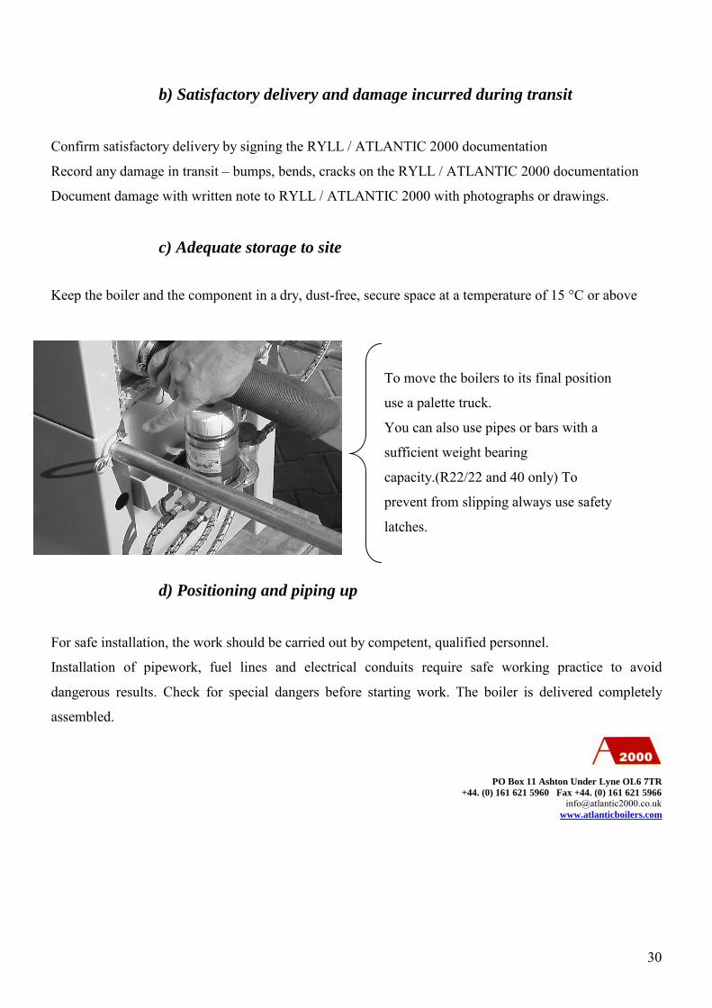
To move the boilers to its final position
use a palette truck.
You can also use pipes or bars with a
sufficient weight bearing
capacity.(R22/22 and 40 only) To
prevent from slipping always use safety
latches.
b) Satisfactory delivery and damage incurred during transit
Confirm satisfactory delivery by signing the RYLL / ATLANTIC 2000 documentation
Record any damage in transit – bumps, bends, cracks on the RYLL / ATLANTIC 2000 documentation
Document damage with written note to RYLL / ATLANTIC 2000 with photographs or drawings.
c) Adequate storage to site
Keep the boiler and the component in a dry, dust-free, secure space at a temperature of 15 °C or above
d) Positioning and piping up
For safe installation, the work should be carried out by competent, qualified personnel.
Installation of pipework, fuel lines and electrical conduits require safe working practice to avoid
dangerous results. Check for special dangers before starting work. The boiler is delivered completely
assembled.
PO Box 11 Ashton Under Lyne OL6 7TR+44. (0) 161 621 5960 Fax +44. (0) 161 621 5966

31
Following the assembly instruction, carry out the final assembly. If a BSV (a balancing & sedimentation
vessel) is not fitted, a by-pass valve is recommended between the heating flow and heating return.
The following circuits are required:
Ι) space heating circuit (s)
ΙΙ) domestic hot water generator (if fitted)
ΙΙΙ) cold water feed and expansion
VΙ) fresh air inlet and flue gas outlet or a balanced flue
V) condensate drain
VΙ) fuel supply
The boiler will require pressure testing with the connected systems to the normal test pressure of 3 BARS.
The boiler will require a safety valve set at the normal maximum working pressure of 3 BARS.
The condensate arising in the condensing heat exchanger is collected and neutralised to waste water
quality.
The provisions of the local water and sewage authority should be considered in relation to the condensate
effluent.
e) Commissioning and preventive maintenance
Commissioning should be carried out by ATLANTIC 2000 or an authorised agent.
During commissioning, all boiler functions should be verified and set in accordance with the installation
and recorded in the commissioning certificate. The end user, or his appointee, can be instructed in the use
and maintenance of the boilerplant. Any major problems should be referred to ATLANTIC 2000 or its
agents. ATLANTIC 2000 advises that the R series is serviced
Every year or every 2500 to 3000 hours run (whichever comes first) for gas or LPG fired boilers
Every six-months or every 1500 to 2000 hours run (whichever comes first) for oil, keresone or
B100 bio-diesel fired boilers.
o For B100 bio-diesel fired boilers every three months a light burner service,
every six months a major boiler and burner service
PO Box 11 Ashton Under Lyne OL6 7TR+44. (0) 161 621 5960 Fax +44. (0) 161 621 5966

32
f) The boiler room
The boiler room must be dry and dust-free.
The boiler room must be exclusive for boilerplant and other items involved with heating, domestic hot
and cold water supply, ventilation and air conditioning and similar service.
The burner and its fuel supply must be easily isolated, electrically & mechanically, from a easily
noticeable emergency switch outside the boiler room.
Any oil storage will be remote from the boiler room and its supply to the boiler room easily isolated by
the emergency switch.
Boiler base
The boiler base must be level and incombustible.
g) Flue gas extract system
The flue gases extract system must be constructed and installed to appropriate condensing flue regulations
I) Select fresh air & flue gas tubes based on advice from ATLANTIC 2000
II) The flue gas extract system will operate in both positive and negative
pressures – check joints
III) The flue gas extract system should allow 2-3% slope for condensate to
drain back to the neutralization box
IV) Avoid oils, fats or solvents on the tubes
PO Box 11 Ashton Under Lyne OL6 7TR+44. (0) 161 621 5960 Fax +44. (0) 161 621 5966

33
REAR OF BOILER
Fresh air intake
h) Fresh air supply for combustion
Fresh air is drawn from outside and pre-heated in the condensing heat exchanger.
I) Where possible, draw air downwards from the same chimney that serves
the flue gas extract tube.or, draw the air from convenient side wall
II) Avoid drawing in dusty or contaminated air
III) Use appropriate grades of plastic tube – uPVC or PP.
IV) Size the fresh air tubes at least as large as inlet connection.
If necessary, reduce the tube size at the condensing heat exchanger.
V) As a general rule, place the external air inlet approximately 400mm below
the flue gas extract terminal, or not less than 150mm below the exhaust flue on a vertical
outlet.
VI) Both fresh air inlet and flue extract gas outlet terminals should be fitted
with a bull-nose bird 25mm mesh. The fresh air inlet terminal should not admit rain. The flue
extract gas outlet can admit rain.
PO Box 11 Ashton Under Lyne OL6 7TR+44. (0) 161 621 5960 Fax +44. (0) 161 621 5966
TThe flue gas extract fan (s) are part of the boiler purchase. They are included
in the boiler case (R22/22,40) or separated and can be mounted at any point
in the extract system.
The matters of condensate draining and pressure must be considered
34
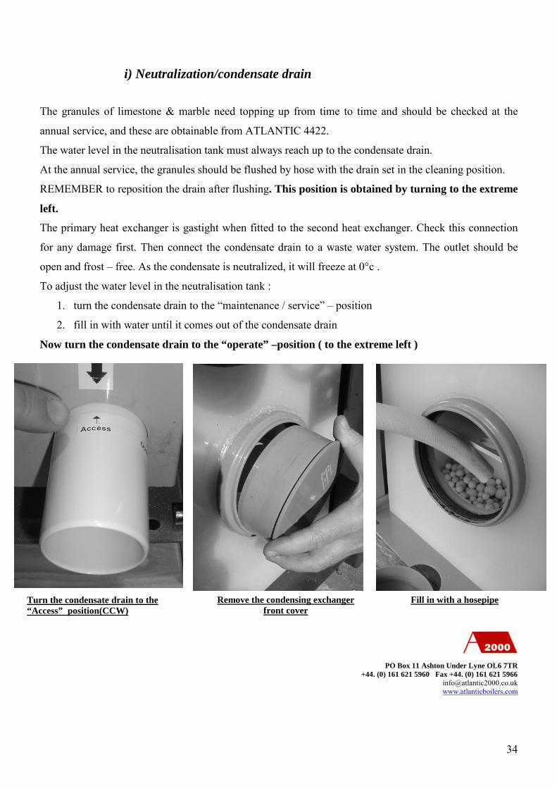
i) Neutralization/condensate drain
The granules of limestone & marble need topping up from time to time and should be checked at the
annual service, and these are obtainable from ATLANTIC 4422.
The water level in the neutralisation tank must always reach up to the condensate drain.
At the annual service, the granules should be flushed by hose with the drain set in the cleaning position.
REMEMBER to reposition the drain after flushing. This position is obtained by turning to the extreme
left.
The primary heat exchanger is gastight when fitted to the second heat exchanger. Check this connection
for any damage first. Then connect the condensate drain to a waste water system. The outlet should be
open and frost – free. As the condensate is neutralized, it will freeze at 0°c .
To adjust the water level in the neutralisation tank :
1. turn the condensate drain to the “maintenance / service” – position
2. fill in with water until it comes out of the condensate drain
Now turn the condensate drain to the “operate” –position ( to the extreme left )
PO Box 11 Ashton Under Lyne OL6 7TR+44. (0) 161 621 5960 Fax +44. (0) 161 621 5966
Turn the condensate drain to the“Access” position(CCW)
Remove the condensing exchangerfront cover
Fill in with a hosepipe
35
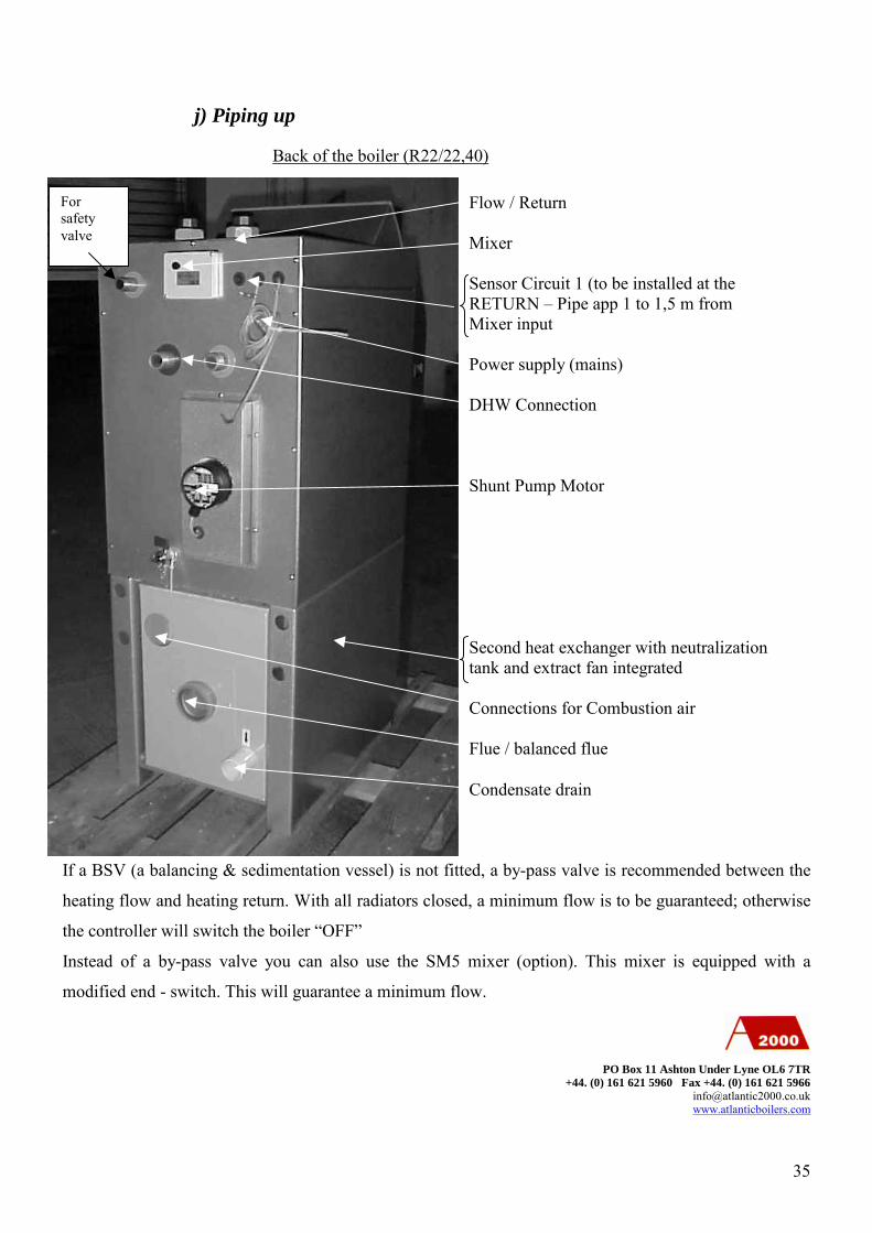
j) Piping up
If a BSV (a balancing & sedimentation vessel) is not fitted, a by-pass valve is recommended between the
heating flow and heating return. With all radiators closed, a minimum flow is to be guaranteed; otherwise
the controller will switch the boiler “OFF”
Instead of a by-pass valve you can also use the SM5 mixer (option). This mixer is equipped with a
modified end - switch. This will guarantee a minimum flow.
PO Box 11 Ashton Under Lyne OL6 7TR+44. (0) 161 621 5960 Fax +44. (0) 161 621 5966
Back of the boiler (R22/22,40)
Flow / Return
Mixer
Sensor Circuit 1 (to be installed at theRETURN – Pipe app 1 to 1,5 m fromMixer input
Power supply (mains)
DHW Connection
Shunt Pump Motor
Second heat exchanger with neutralizationtank and extract fan integrated
Connections for Combustion air
Flue / balanced flue
Condensate drain
Forsafetyvalve

36
Condensate drain
Back of the boiler (R22/90,150,300,400,500, 600)
The following circuits are required:
Ι) space heating circuit (s)
ΙΙ) domestic hot water generator (if fitted)
Heating circuit 2 is picked up from the flow connection of DHW.
For special arrangements i. E. R22 can be combined with an additional wood-fired boiler, solar panels, a
heat pump or a CHP unit, ask ATLANTIC2000 for piping and controller information.
A domestic hot water generator can be supplied with a two port control; when the controller of the boiler
switches the flow-pump on and off.
PO Box 11 Ashton Under Lyne OL6 7TR+44. (0) 161 621 5960 Fax +44. (0) 161 621 5966
DHW Return
Flow
Motorized valveReturn
Motor
DHW Flow
Shunt pump
Boiler return sensor
Combustion air intake
Flue outlet

37
For detailed information about the controller and controller extension modules see the CONTROLLER
MANUAL.
Combustion low pressure board / low pressure sensor
The combustion low-pressure system consists of: the low-pressure board, the low-pressure switch (under
the top cover of the boiler), the burner nipple and a silicone –tube connecting nipple and switch. The
working pressure (0.25 mbars) is logged by the switch and controlled by the pressure board, which then
controls the speed of the draught fan. It is important, that the tube is securely fitted to the nipple and to the
pressure switch.
The sensor has two connectors. If the connectors are wrong fitted, the result will cause a pressure fault !
PO Box 11 Ashton Under Lyne OL6 7TR+44. (0) 161 621 5960 Fax +44. (0) 161 621 5966

38
k) Burner and fuel supply
Always check the burner model fuel supply!
The following burner models are possible: -Fuel oil
-Kerosene
-B100 oil
-Natural Gas
-Butane or propane
With delivery of oil always turn off the boiler throughout the delivery period required to re-fill the storage
tank, and for a further period of 30 minutes thereafter.
With an oil burner ensure that the fuel pipe is completely sealed at all joints. Bubbles in the fuel pipe or in
the pump may cause damages to the burner. Long pipes runs need to be before burner start.
Check the burner low pressure and combustion emission values regularly.
Check the low-pressure value, it should be between 0.20 and 0.30 mbar.
For further information please see burner manual.
Check CO2/Nox/Sox/CO
To check, use the measuring test point in the second heat exchanger
Depth: 105 mm - 22 KW 120 mm - 40 KW
PO Box 11 Ashton Under Lyne OL6 7TR+44. (0) 161 621 5960 Fax +44. (0) 161 621 5966

39
15) MAINTENANCE
Before any maintenance operation, make sure that the burner; the power supply and
the controller are switched-off (N1) (burner to be switched off before mains supply)
A) Cleaning of the main heat exchanger:
1. Lift up and remove the front cover.(up to 150kW)
2. Unplug the burner electrical and fuel connections.
3. Remove the burner
4. Unbolt the cleaning panel (N36) and remove it.
5. Clean the main heat exchanger with a vacuum cleaner and a brush as shown below
6. After full cleaning, put the cleaning panel into position (N36)
B) Carefully service the burner and replace any parts if required
C) Cleaning of the condensing exchanger
1. Turn the condensate drain to the “maintenance position” (CW)
2. Remove the condensing exchanger front cover (N35)
3. Push the plastic plate back (N34)
4. Flush inside the exchanger with a hosepipe
5. Stir the granules of limestone & marble to avoid them forming a concrete block
6. Replace granules of limestone & marble if required
N36

40
7. Fill the exchanger with clean water
8. Pull the plastic plate out (N34)
9. Put the condensing exchanger front cover (N35) back in place.
10. Turn the condensate drain back to the “working position”
E) Put the burner back into position
D) Visually check all the parts of the boiler.
F) Switch the boiler back on (N1)
G) Adjust the combustion settings (refer to commissioning procedure)
PO Box 11 Ashton Under Lyne OL6 7TR+44. (0) 161 621 5960 Fax +44. (0) 161 621 5966
Turn the condensate drainto “ACCESS” (CCW)
N35
Remove the cover using thehandle
Push the plastic platebackward
Flush with a hosepipe

41
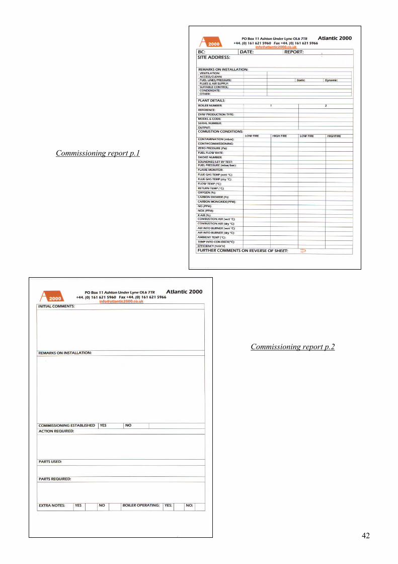
14) COMMISSIONING
All Atlantic boilers and water heaters are thoroughly tested for mechanical, electrical and combustion
performance at the factory. The combustion performance tests are based on gas equivalent to the North
Sea natural gas provided by British Gas and at low pressures normally supplied. The test takes up to two
hours and the results are recorded.
The prime object of the site commissioning of the boiler(s) is, subject to installed conditions, to match the
optimum combustion performance results reached at the factory and to ensure the boiler(s) is/are installed
according to the conditions of guarantee. The following check list should be satisfied before the
commissioning takes place. To arrange the commissioning Atlantic should be given a minimum of ten
days notice of the date and time required.
After commissioning, a report will be sent to the installer.
Commissioning sheet
42
Commissioning report p.1
Commissioning report p.2
43
Pre-commissioning checks
-Check that boilerhouse ventilation is adequate.
-Check that boiler fresh air supply is adequate.
-Check that boilerhouse is clean and that boiler(s) is (are) accessible
-Check that the boiler is filled with clean water
-Check the pressure of the system
-Check that water strainers have been installed before the boiler
-Check the the fuel lines are installed properly, tested and primed
-Check that there is adequate fuel supply on site
-Check that the condensing exchanger has been connected to the drain
-Check that the condensing exchanger has been filled with water
-Check that the flue has a slope in order to gather the condensate in the condensing heat exchanger
-Check that power supply and permanent electrical wiring is available
-Check that the control sensor is installed and connected
-Check that the outside sensor is installed and connected
-Check that all motors have correct roation
-Check that control/management system is in operation
-Check that heating load is ready for commissioning
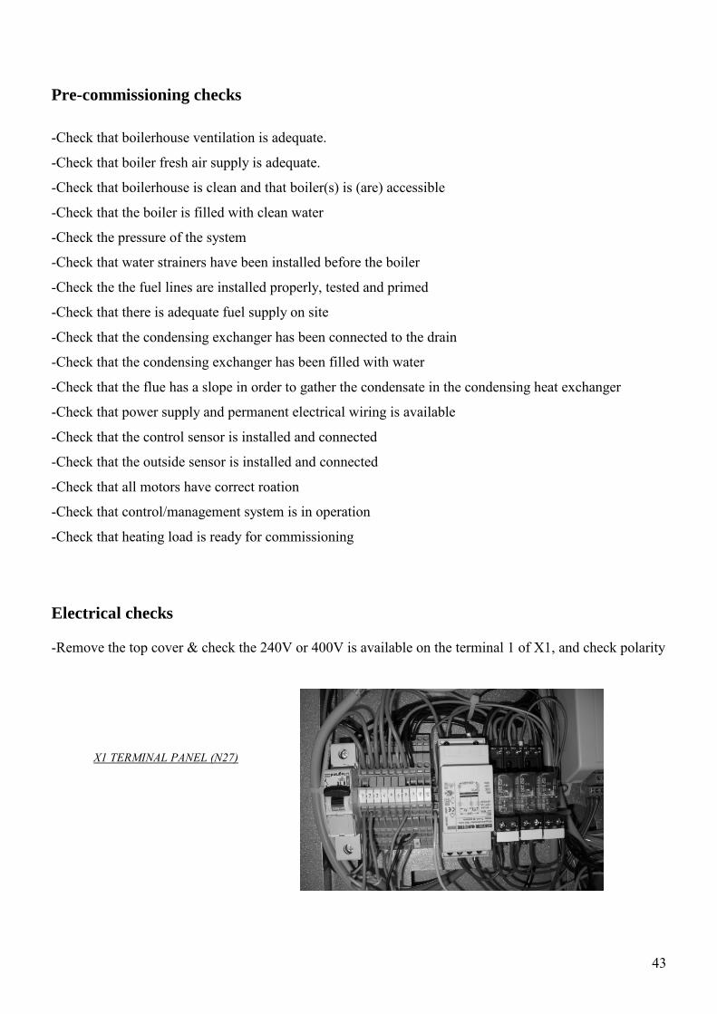
Electrical checks
-Remove the top cover & check the 240V or 400V is available on the terminal 1 of X1, and check polarity
X1 TERMINAL PANEL (N27)

44
-Check that the control sensor (strapped or pocket N31, N32) is connected to the correct terminal
(terminal 12 of X1 for weather compensation or terminal 14 of X1 for constant temperature
-Check the BMS enable signal wires (terminal 11 of X1 for weather compensation or terminal 13 of X1
for constant temperature) are connected to the correct terminals and that is operating properly and
override the control sensor
-Check that there are no loose connections in the control panel
Procedure
-Before starting the boiler move manually the diverting valve to avoid blockage
-Disconnect the burner plug (N5)
-Connect the fan controller (Atlantic staff only)
-Start the boiler with the main switch (N1)
-Wait around 3 minutes for initialisation of software; the main display will show “INIT” on the top right
side.
-After initialisation, the main display will show “RUN” on the top right side, the shunt pump will start
automatically, check for air lock and check correct rotation
-Check the flow & return temperature on the controller
-Check fan rotation (anticlockwise)
-Remove and check burner settings (according to burner manual)
-Open the gas or the oil valve
-Connect the burner plug
-Commission the burner (according to burner manual)
Important note concerning Pressure
The R Series design is different to any conventional boilers. 2 sets of fans (burner fans and exhaust draftfans) need to work together in order to achieve the benefit of the efficiency.The exhaust draft fan(s) speed is adjusted in order to keep the combustion chamber pressure around –0.25mbar. The pressure board will automatically adjust the fan(s) speed to keep these conditions insidethe combustion chamber.Consequently the burner and the exhaust draft fans are compulsory elements of the boilers and need torun together.Should the pressure board unable to satisfy the requirements, boiler will lock out after 10 attempts ofaround 3 minutes each.Should this happen, the combustion chamber pressure can be checked using the inspection point N17. Ifthe pressure is different than –0.25mb, check the burner output, reduce if necessary, should the problemcontinue, than fans settings adjustment are required, please ring Atlantic. If the pressure is –0.25mb thanrefer to part D of the fault finding chart.

45
Important note for flue gas test point
The adjustment of the burner settings (Co, Nox…) should be done using the flue gas test point (N33) forthe flue analyser. . Overall efficiency of the boiler should be read after the condensing heat exchangerafter the fan.
Boiler ModelFlue gas test point
depthR22/22 105mm
R22/40 120mm
R22/60 120mm
R22/90 140mm
R22/150 140mm
R22/200 140mm
R22/300 270mm
R22/400 270mm
R22/500 270mm
R22/600 270mm
Safety Checks
-Switch the shunt pump off
-Leave the burner running until the boilers goes to lockout on high limit stats.
-If the boiler flow goes over 120ºC or 2.5 bars, disconnect immediately the burner (N5) and check the
high limit stats ( N18, N21)
-After safety checks, switch the shunt pump back on
46
17) THE GUARANTEE ON THE R SERIES
This guarantee is to the purchaser of the boiler(s) who is deemed to be the installer. If the boiler(s) is (are)purchased by the eventual user who then arranges to install boiler(s), the eventual user is deemed to be theinstaller. The details of the guarantee are given to assist the installer in obtaining effective action withinthe guarantee and they are in addition to the installer’s legal rights under the relevant statutory enactmentsfor the time being in force in England, Wales, and Scotland.Oil, gas or electrical equipment:The replacement or repair of the item, including the cost of its delivery to the site of the installation or itsequal within England, Wales and Scotland, provided that the defect or flaw occurs within 2 calendar yearsof the commissioning date.Removable component of the boiler assembly (other than the gas or electrical equipment)The replacement or repair of the item, including the cost of its delivery to the site of the installation or itsequal within England Wales and Scotland if the defect or flaw occurs within 2 calendar years of thecommissioning date.The main body of the boiler.The repair of any defects in the main and condensing heat exchanger of the boiler including any necessaryremoval or replacement of that part of the boiler on site if the defect occurs within 3 calendar years of thecommissioning date.Definitions:The effective actions stipulated in this guarantee are subject to the purchaser complying completely withthe following:
1) The boilers are installed according to the recommendations of this technical booklet, therecommended codes of practice of the C.I.B.S. and the B.S.I..
2) The commissioning of the boiler by ACM Atlantic and their regular annual servicing andmaintenance, together the correction of any errors of installations reported by ACM Atlantic.
3) The payment in full, by the purchaser unless otherwise agreed, of the invoice for the supply anddelivery of the boiler(s) to site, any other relevant invoices connected with the boiler positioningand fixing, and the invoices for commissioning and any correction of installation error, all to bemade within one calendar month of the date of the invoice.
4) The presentation, at the time of a claim under the guarantee, of the boiler registration number, thecommissioning record with date, and the necessary information for defining any replacement part.
5) When a replacement item is supplied for a defective item, the defective item must be returned toACM Atlantic at their registered office within 6 weeks of the date of notification of the defectcarefully labeled with registration number of the boiler and the name and the order reference ofthe purchaser of the boiler. If this is not complied with, the purchaser will be charged with the costof the item and its delivery.