Embed Size (px)
Citation preview
SEMI Draft Document 3626 2003/04/23OASISTM - Open Artwork System Interchange Standard
ns
i-
1 Purpose
1.1 The purpose of this specification is to define aninterchange and encapsulation format for hierarchicalintegrated circuit mask layout information.
1.2Background—In the fall of 2001, SEMI’s Data PathTask Force formed a working group to define a succesor to the venerable GDSII Stream format, which hadserved the I.C. industry as ade factostandard for layoutinterchange for more than two decades. The old formalimited by 16-bit and 32-bit internal integer fields, by itsinefficient representation of cell-native geometric fig-ures, and by high structural overhead, was becomingdifficult to use for leading-edge designs, and file sizeswere becoming unwieldy, in some cases growing tomany tens of gigabytes. The successor format was chtered with several overall goals:
• Achieve at least an order-of-magnitude file sizimprovement compared to GDSII Stream.
• Remove all 16-bit and 32-bit integer width restrictions—make the new format fully 64-bit capable.
• Efficiently represent cells with large payloads of flanative geometric figures.
• Provide a richer information palette to facilitate interchange of layout-related information between desigand manufacturing.
In the months leading up to the formation of the SEMData Path Task Force, International Sematech sponsoa series of meetings focusing on Mask EDA issues.Many of the Task Force participants were also involvein these Sematech meetings, and carried forward muuseful information from those sessions into the defini-tion of this specification.
2 Scope
2.1 This format is designed primarily to encapsulatehierarchical mask layout for interchange between systems such as EDA software, mask writing tools, andmask inspection/repair tools.
2.2 This format is designed to be both hardware- andsoftware-independent.
SEMI Draft Document 3626 2003/04/23 1
s-
t,
ar-
e
-
t
-n
Ired
dch
-
3 Limitations
3.1 Use of extension records such as XNAME, XELE-MENT, and XGEOMETRY may impair interoperabilitybetween tools. It is recommended that these extensiobe used primarily for prototyping, and that interopera-bility be maintained through the formal inclusion ofextensions to this specification.
4 Referenced Standards
4.1 IEEE Standards1
IEEE 754-1985 - IEEE Standard for Binary Floating-Point Arithmetic
4.2 ISO Standards2
ISO-646-IRV - “US-ASCII” Character Set
ISO-3309 - Information technology—Telecommunica-tions and information exchange between systems—High-level data link control (HDLC) procedures—Frame structure
4.3 IETF Standards3
RFC 1951 - DEFLATE Compressed Data Format Specfication version 1.3
1. Institute of Electrical and Electronics EngineersIEEE Operations Center, 445 Hoes Lane, P.O. Box 1331, Piscat-away, New Jersey 08855-1331, USA. Telephone: 732-981-0060;FAX: 732-981-1721.Website: www.ieee.org
2. International Organization for StandardizationISO Central Secretariat, 1, rue de Varembé, Case postale 56,CH-1211 Geneva 20, Switzerland. Telephone: 41-22-749-01-11;FAX: 41-22-733-34-30Website: www.iso.ch
3. Internet Engineering Task ForceWebsite: www.ietf.org
© SEMI 2003
5 Terminology
5.1 Abbreviations and Acronyms
5.1.1BNF—Backus-Naur Form
5.1.2EDA—Electronic Design Automation
5.1.31OASISTM—Open Artwork System InterchangeStandard
5.2 Definitions
5.2.1 Most definitions of terminology specific to OASISare found within the text of the paragraphs that contaithem.
5.2.2Cell—a named object in a layout hierarchy, con-taining native geometric information, annotation infor-mation, and/or placements of other cells.
5.2.3Placement—a specification by reference that acopy of a cell is to be placed within the coordinate spacof another cell at a particular location, orientation, andscale. Cell placement is the fundamental mechanismwhich makes hierarchy within the OASIS file possible
5.2.4Geometry—a two-dimensional geometric figuresuch as a polygon, rectangle, trapezoid, path, circle, ewith inherent attributes oflayer anddatatype.
5.2.5Property—an annotation element consisting of aname plus an optional list of values, supplying descriptive information about the characteristics of the file orone of its components.
5.2.6Record—the principal data division in an OASISfile.
5.2.7Text Element—an annotation element consisting oan (x,y) coordinate point and an associated string.
5.3 Symbols
5.3.1“->” — indicates a mapping of an argument to itcontents or its meaning.
1. Used with consent by the owner.
© SEMI 2003 2
n
e
.
tc.
-
f
s
SEMI Draft Document 3626 2003/04/23
e
nions.
t hier- Each
ct
ocu-e consid-ye (suchers to
n the
e actual
6 OASIS BASICS
6.1 An OASIS file is a sequence ofbytesdivided intorecords. The length of a record is discernible from its structurand is not explicit (in contrast to GDSII Stream, where all record lengths are explicit).
6.2 An OASIS file has the following overall syntax (using the modified BNF notation described in section 36 opage 30). Individual record types appear in bold uppercase and are described in more detail in following sect
<oasis-file> -> <magic-bytes>START { CBLOCK | PAD | PROPERTY | <cell> | <name> }*END<name> -> {CELLNAME | TEXTSTRING | LAYERNAME | PROPNAME | PROPSTRING | XNAME }<cell> -> { CELL { CBLOCK | PAD | PROPERTY | XYRELATIVE | XYABSOLUTE | <element> }* }<element> -> { <geometry> |PLACEMENT | TEXT | XELEMENT }<geometry> -> {RECTANGLE | POLYGON | PATH | TRAPEZOID | CTRAPEZOID | CIRCLE | XGEOMETRY }
6.3 An OASIS file may represent a complete layout hierarchy, a portion of a layout hierarchy, or multiple layouarchies. These interpretations are not intrinsic to the format and are governed by application semantics only.OASIS file must be syntactically complete—it must begin with <magic-bytes> and contain at least aSTART andEND record.
6.4 The <magic-bytes> element is a sequence of 13 ASCII characters: “%SEMI-OASIS<CR><NL>” where<CR><NL> represents the ASCII hexadecimal sequence0D 0A. It is provided as a recognition signature to makeOASIS files easily identifiable to the UNIXfile utility. (The intent of the carriage return and newline is to help detecorruption by FTP programs operating in non-binary mode.)
6.5EXCEPTIONHANDLING: OASIS processors should treat any deviation from the syntax presented in this dment as a fatal error. OASIS readers are not required to implement syntax-check preprocessing in order to bered compliant with this specification. The sequence in which exceptions are detected and reported is entirelapplication-dependent. In addition, for access requests which do not require the interpretation of the entire filas retrieval of a single cell or a subset of the cells within the file), this specification does not require OASIS readexhaustively check the validity of the entire file.
7 DATA CONSTRUCTS
7.1 BYTES
7.1.1 A byte is a fixed-length 8-bit value. Bit patterns for bytes are shown with the least significant bit (bit 0) oright.
7.2 INTEGERS
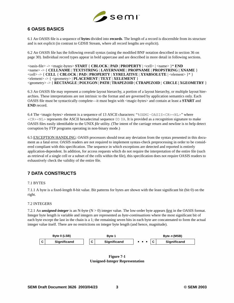
7.2.1 Anunsigned-integer is an N-byte (N > 0) integer value. The low-order byte appearsfirst in the OASIS format.Integer byte length is variable and integers are represented asbyte-continuations where the most significant bit ofeach byte except the last in the chain is a 1; the remaining seven bits in each byte are concatenated to form thinteger value itself. There are no restrictions on integer byte length (and hence, magnitude).
Figure 7-1Unsigned-Integer Representation
C Significand C Significand. . .Byte 0 (LSB) Byte 1 Byte n (MSB)
C Significand
SEMI Draft Document 3626 2003/04/23 3 © SEMI 2003
w-th rep-
2-bit
ntated by
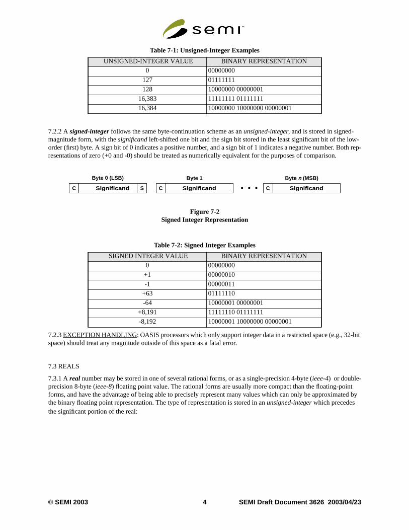
7.2.2 Asigned-integer follows the same byte-continuation scheme as anunsigned-integer, and is stored in signed-magnitude form, with thesignificand left-shifted one bit and the sign bit stored in the least significant bit of the loorder (first) byte. A sign bit of 0 indicates a positive number, and a sign bit of 1 indicates a negative number. Boresentations of zero (+0 and -0) should be treated as numerically equivalent for the purposes of comparison.
Figure 7-2Signed Integer Representation
7.2.3EXCEPTIONHANDLING: OASIS processors which only support integer data in a restricted space (e.g., 3space) should treat any magnitude outside of this space as a fatal error.
7.3 REALS
7.3.1 Areal number may be stored in one of several rational forms, or as a single-precision 4-byte (ieee-4) or double-precision 8-byte (ieee-8) floating point value. The rational forms are usually more compact than the floating-poiforms, and have the advantage of being able to precisely represent many values which can only be approximthe binary floating point representation. The type of representation is stored in anunsigned-integer which precedesthe significant portion of the real:
Table 7-1: Unsigned-Integer Examples
UNSIGNED-INTEGER VALUE BINARY REPRESENTATION
0 00000000
127 01111111
128 10000000 00000001
16,383 11111111 01111111
16,384 10000000 10000000 00000001
Table 7-2: Signed Integer Examples
SIGNED INTEGER VALUE BINARY REPRESENTATION
0 00000000
+1 00000010
-1 00000011
+63 01111110
-64 10000001 00000001
+8,191 11111110 01111111
-8,192 10000001 10000000 00000001
C Significand C Significand. . .Byte 0 (LSB) Byte 1 Byte n (MSB)
C SignificandS
© SEMI 2003 4 SEMI Draft Document 3626 2003/04/23
the54-
side
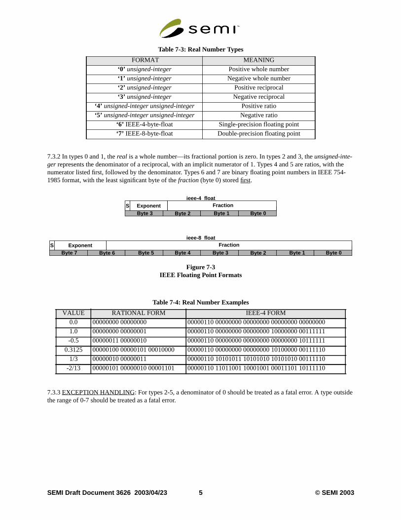
7.3.2 In types 0 and 1, thereal is a whole number—its fractional portion is zero. In types 2 and 3, theunsigned-inte-ger represents the denominator of a reciprocal, with an implicit numerator of 1. Types 4 and 5 are ratios, withnumerator listed first, followed by the denominator. Types 6 and 7 are binary floating point numbers in IEEE 71985 format, with the least significant byte of thefraction (byte 0) storedfirst.
Figure 7-3IEEE Floating Point Formats
7.3.3EXCEPTIONHANDLING: For types 2-5, a denominator of 0 should be treated as a fatal error. A type outthe range of 0-7 should be treated as a fatal error.
Table 7-3: Real Number Types
FORMAT MEANING
‘0’ unsigned-integer Positive whole number
‘1’ unsigned-integer Negative whole number
‘2’ unsigned-integer Positive reciprocal
‘3’ unsigned-integer Negative reciprocal
‘4’ unsigned-integer unsigned-integer Positive ratio
‘5’ unsigned-integer unsigned-integer Negative ratio
‘6’ IEEE-4-byte-float Single-precision floating point
‘7’ IEEE-8-byte-float Double-precision floating point
Table 7-4: Real Number Examples
VALUE RATIONAL FORM IEEE-4 FORM
0.0 00000000 00000000 00000110 00000000 00000000 00000000 00000000
1.0 00000000 00000001 00000110 00000000 00000000 10000000 00111111
-0.5 00000011 00000010 00000110 00000000 00000000 00000000 10111111
0.3125 00000100 00000101 00010000 00000110 00000000 00000000 10100000 00111110
1/3 00000010 00000011 00000110 10101011 10101010 10101010 00111110
-2/13 00000101 00000010 00001101 00000110 11011001 10001001 00011101 10111110
Byte 0Byte 1Byte 2Byte 3
ieee-4 floatS Exponent Fraction
Byte 0Byte 1Byte 2Byte 3Byte 4Byte 5Byte 6Byte 7
ieee-8 floatS Exponent Fraction
SEMI Draft Document 3626 2003/04/23 5 © SEMI 2003
e. An a
r of
irec-ent is
ode
ce-, 6 formagni-
al dis-as a
eger). Theist of
7.4 STRINGS
7.4.1 Astring is a sequence of zero or more bytes (“characters”) preceded by anunsigned-integer representing thenumber of characters in the string:
string -> length byte*
Strings in OASIS are further sub-typed by semantic. Ab-string (“binary string”) is a string which may contain anycombination of 8-bit character codes in any sequence. Ana-string (“ASCII string”) may contain onlyprintableASCII character codes (hexadecimal 21-7E) plus the SP (space) character (hexadecimal 20), in any sequencn-string (“name string”) may contain onlyprintable ASCII character codes (hexadecimal 21-7E), and must havelength greater than zero.
7.4.2 The set ofprintable ASCII characters consists of hexadecimal character codes 21-7E. In ascending ordecharacter code, we have:
!"#$%&’()*+,-./0123456789:;<=>?@ [21-40]ABCDEFGHIJKLMNOPQRSTUVWXYZ[\]^_‘ [41-60]abcdefghijklmnopqrstuvwxyz{|}~ [61-7E]
This excludes space (SP), tabs (HT, VT), and all other control characters.
7.4.3EXCEPTION HANDLING: OASIS processors should treat illegal characters ina-strings or n-strings as fatalerrors. Zero-lengthn-strings should also be treated as fatal errors.
7.5 DELTAS
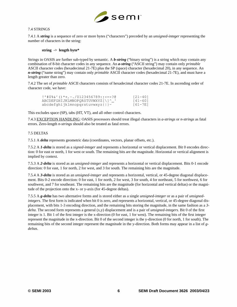
7.5.1 Adelta represents geometric data (coordinates, vectors, planar offsets, etc.).
7.5.2 A1-deltais stored as asigned-integer and represents a horizontal or vertical displacement. Bit 0 encodes dtion: 0 for east or north, 1 for west or south. The remaining bits are the magnitude. Horizontal or vertical alignmimplied by context.
7.5.3 A2-deltais stored as anunsigned-integer and represents a horizontal or vertical displacement. Bits 0-1 encdirection: 0 for east, 1 for north, 2 for west, and 3 for south. The remaining bits are the magnitude.
7.5.4 A3-deltais stored as anunsigned-integer and represents a horizontal, vertical, or 45-degree diagonal displament. Bits 0-2 encode direction: 0 for east, 1 for north, 2 for west, 3 for south, 4 for northeast, 5 for northwestsouthwest, and 7 for southeast. The remaining bits are the magnitude (for horizontal and vertical deltas) or thetude of the projection onto the x- or y-axis (for 45-degree deltas).
7.5.5 Ag-delta has two alternative forms and is stored either as a singleunsigned-integer or as a pair ofunsigned-integers. The first form is indicated when bit 0 is zero, and represents a horizontal, vertical, or 45-degree diagonplacement, with bits 1-3 encoding direction, and the remaining bits storing the magnitude, in the same fashion3-delta. The second form represents a general (x,y) displacement and is a pair ofunsigned-integers. Bit 0 of the firstinteger is 1. Bit 1 of the first integer is the x-direction (0 for east, 1 for west). The remaining bits of the first intrepresent the magnitude in the x-direction. Bit 0 of the second integer is the y-direction (0 for north, 1 for southremaining bits of the second integer represent the magnitude in the y-direction. Both forms may appear in a lg-deltas.
© SEMI 2003 6 SEMI Draft Document 3626 2003/04/23
of the
Figure 7-4Delta Types
7.6 REPETITIONS
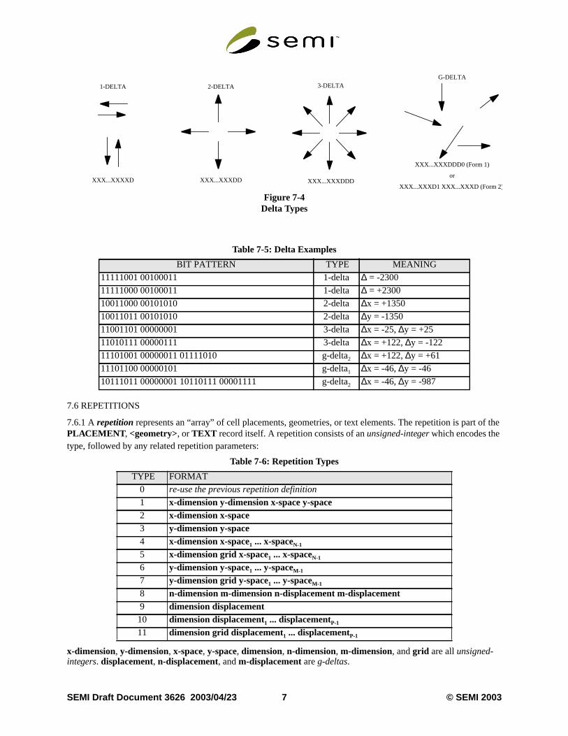
7.6.1 Arepetitionrepresents an “array” of cell placements, geometries, or text elements. The repetition is partPLACEMENT , <geometry>, or TEXT record itself. A repetition consists of anunsigned-integerwhich encodes thetype, followed by any related repetition parameters:
x-dimension, y-dimension, x-space, y-space, dimension, n-dimension, m-dimension, andgrid are allunsigned-integers. displacement, n-displacement, andm-displacement areg-deltas.
Table 7-5: Delta Examples
BIT PATTERN TYPE MEANING
11111001 00100011 1-delta∆ = -2300
11111000 00100011 1-delta∆ = +2300
10011000 00101010 2-delta∆x = +1350
10011011 00101010 2-delta∆y = -1350
11001101 00000001 3-delta∆x = -25,∆y = +25
11010111 00000111 3-delta∆x = +122,∆y = -122
11101001 00000011 01111010 g-delta2 ∆x = +122,∆y = +61
11101100 00000101 g-delta1 ∆x = -46,∆y = -46
10111011 00000001 10110111 00001111 g-delta2 ∆x = -46,∆y = -987
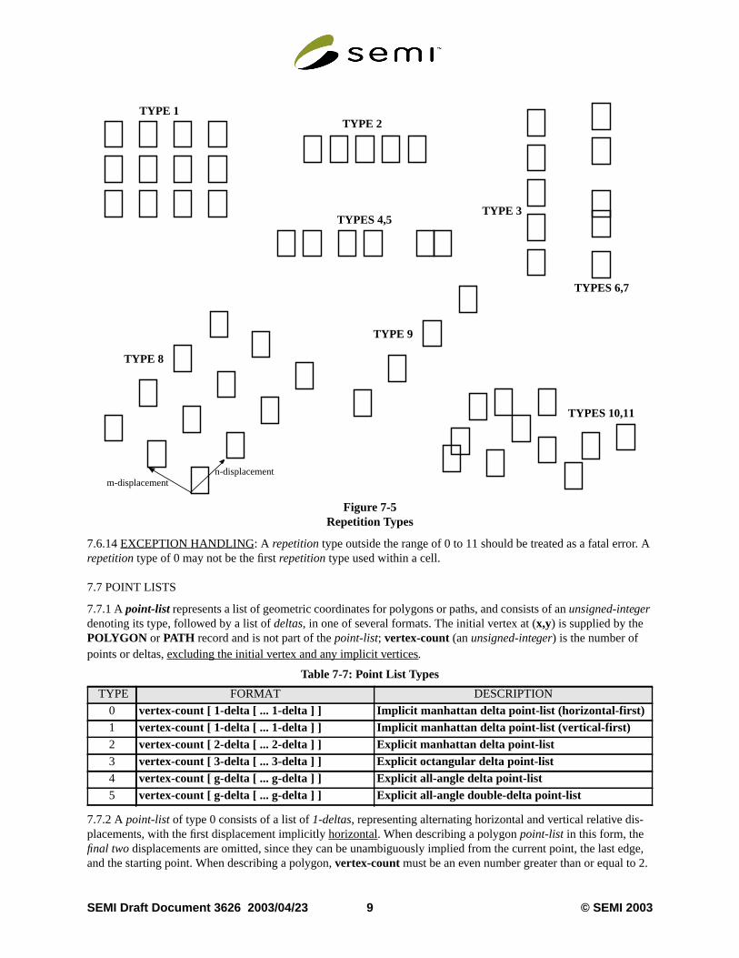
Table 7-6: Repetition Types
TYPE FORMAT
0 re-use the previous repetition definition
1 x-dimension y-dimension x-space y-space2 x-dimension x-space3 y-dimension y-space4 x-dimension x-space1 ... x-spaceN-1
5 x-dimension grid x-space1 ... x-spaceN-1
6 y-dimension y-space1 ... y-spaceM-1
7 y-dimension grid y-space1 ... y-spaceM-1
8 n-dimension m-dimension n-displacement m-displacement9 dimension displacement10 dimension displacement1 ... displacementP-1
11 dimension grid displacement1 ... displacementP-1
2-DELTA
XXX...XXXDD
3-DELTA
XXX...XXXDDD
G-DELTA
XXX...XXXDDD0 (Form 1)
or
XXX...XXXD1 XXX...XXXD (Form 2 )
1-DELTA
XXX...XXXXD
SEMI Draft Document 3626 2003/04/23 7 © SEMI 2003
of
thef
ef
n the
is
dis-
7.6.2TYPE 0 indicates that the previous repetition description, stored in modal variablerepetition, is to be re-used.(See section 10 on page 12.) No additional values are stored with this type.
7.6.3TYPE 1 is an N-column (N > 1) by M-row (M > 1) matrix with uniform horizontal and vertical spacingbetween the elements.x-dimensionis N - 2 andy-dimensionis M - 2. The (x-offset, y-offset) (cumulative spacing inthe (horizontal,vertical) direction) of element (i,j) of the repetition (i = 0, ..., N-1 and j = 0, ..., M-1) is(i * x-space, j * y-space).
7.6.4TYPE 2 is an N-column (N > 1) by 1-row vector with uniform horizontal spacing between the elements.x-dimension is N - 2. The (x-offset, y-offset) (cumulative spacing in the (horizontal,vertical) direction) of element i the repetition (i = 0, ..., N-1) is (i *x-space, 0).
7.6.5TYPE 3 is a 1-column by M-row (M > 1) vector with uniform vertical spacing between the elements.y-dimen-sion is M - 2. The (x-offset, y-offset) (cumulative spacing in the (horizontal,vertical) direction) of element j of therepetition (j = 0, ..., M-1) is (0, j *y-space).
7.6.6TYPE 4 is an N-column (N > 1) by 1-row vector with (potentially) non-uniform horizontal spacing betweenelements.x-dimension is N - 2. The (x-offset, y-offset) (cumulative spacing in the (horizontal,vertical) direction) oelement i of the repetition (i = 0, ..., N-1) is (x-space0 + ... +x-spacei, 0), withx-space0 = 0.
7.6.7TYPE 5 is identical toTYPE 4, except that all offset values must be multiplied bygrid during expansion of therepetition.
7.6.8TYPE 6 is a 1-column by M-row (M > 1) vector with (potentially) non-uniform vertical spacing between thelements.y-dimension is M - 2. The (x-offset, y-offset) (cumulative spacing in the (horizontal,vertical) direction) oelement j of the repetition (j = 0, ..., M-1) is(0, y-space0 + ... +y-spacej), with y-space0 = 0.
7.6.9TYPE 7 is identical toTYPE 6, except that all offset values must be multiplied bygrid during expansion of therepetition.
7.6.10TYPE 8 is an N (N > 1) by M (M > 1) repetition with uniform and (potentially) diagonal displacementsbetween the elements.n-dimension is N - 2 and m-dimension is M - 2. Definingn-displacement in terms of itscomponentsnx-spaceandny-space(and similarly form-displacement), the (x-offset, y-offset) (cumulative spacingin the (horizontal,vertical) direction) of element (i,j) of the repetition (i = 0, ..., N-1 and j = 0, ..., M-1) is(i * nx-space+ j * mx-space, i * ny-space + j * my-space).
7.6.11TYPE 9 is a P-element (P > 1) repetition with uniform and (potentially) diagonal displacements betweeelements.dimension is P - 2. Definingdisplacement in terms of its componentsx-space andy-space, the (x-offset,y-offset) (cumulative spacing in the (horizontal,vertical) direction) of element k of the repetition (k = 0, ..., P-1)(k * x-space, k * y-space).
7.6.12TYPE 10 is a P-element (P > 1) repetition with (potentially) non-uniform and arbitrary two-dimensional placements between the elements.dimension is P - 2. Definingdisplacementk in terms of its componentsx-spacekandy-spacek, the (x-offset, y-offset) (cumulative spacing in the (horizontal,vertical) direction) of element k of therepetition (k = 0, ..., P-1) is (x-space0 + ... +x-spacek, y-space0 + ... +y-spacek) with x-space0 = y-space0 = 0).
7.6.13TYPE 11 is identical toTYPE 10, except that all offset values must be multiplied bygrid during expansion ofthe repetition.
© SEMI 2003 8 SEMI Draft Document 3626 2003/04/23
r. A
-
edge, 2.
Figure 7-5Repetition Types
7.6.14EXCEPTIONHANDLING: A repetitiontype outside the range of 0 to 11 should be treated as a fatal errorepetition type of 0 may not be the firstrepetition type used within a cell.
7.7 POINT LISTS
7.7.1 Apoint-list represents a list of geometric coordinates for polygons or paths, and consists of anunsigned-integerdenoting its type, followed by a list ofdeltas, in one of several formats. The initial vertex at (x,y) is supplied by thePOLYGON or PATH record and is not part of thepoint-list; vertex-count (an unsigned-integer) is the number ofpoints or deltas,excluding the initial vertex and any implicit vertices.
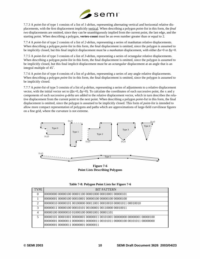
7.7.2 Apoint-list of type 0 consists of a list of1-deltas, representing alternating horizontal and vertical relative displacements, with the first displacement implicitlyhorizontal. When describing a polygonpoint-list in this form, thefinal two displacements are omitted, since they can be unambiguously implied from the current point, the lastand the starting point. When describing a polygon,vertex-count must be an even number greater than or equal to
Table 7-7: Point List Types
TYPE FORMAT DESCRIPTION
0 vertex-count [ 1-delta [ ... 1-delta ] ] Implicit manhattan delta point-list (horizontal-first)1 vertex-count [ 1-delta [ ... 1-delta ] ] Implicit manhattan delta point-list (vertical-first)2 vertex-count [ 2-delta [ ... 2-delta ] ] Explicit manhattan delta point-list3 vertex-count [ 3-delta [ ... 3-delta ] ] Explicit octangular delta point-list4 vertex-count [ g-delta [ ... g-delta ] ] Explicit all-angle delta point-list5 vertex-count [ g-delta [ ... g-delta ] ] Explicit all-angle double-delta point-list
TYPE 1TYPE 2
TYPE 3
TYPES 6,7
TYPES 4,5
TYPES 10,11
TYPE 8
TYPE 9
n-displacementm-displacement
SEMI Draft Document 3626 2003/04/23 9 © SEMI 2003
-
and the
.d to
.d to
d to
entd yrela-
gures
7.7.3 Apoint-list of type 1 consists of a list of1-deltas, representing alternating vertical and horizontal relative displacements, with the first displacement implicitlyvertical. When describing a polygonpoint-list in this form, thefinaltwodisplacements are omitted, since they can be unambiguously implied from the current point, the last edge,starting point. When describing a polygon,vertex-count must be an even number greater than or equal to 2.
7.7.4 Apoint-list of type 2 consists of a list of2-deltas, representing a series of manhattan relative displacementsWhen describing a polygonpoint-list in this form, the final displacement is omitted, since the polygon is assumebe implicitly closed, but this final implicit displacement must be amanhattandisplacement, with either∆x=0 or∆y=0.
7.7.5 Apoint-list of type 3 consists of a list of3-deltas, representing a series of octangular relative displacementsWhen describing a polygonpoint-list in this form, the final displacement is omitted, since the polygon is assumebe implicitly closed, but this final implicit displacement must be anoctangular displacement at an angle that is anintegral multiple of 45˚.
7.7.6 Apoint-list of type 4 consists of a list ofg-deltas, representing a series of any-angle relative displacements.When describing a polygonpoint-list in this form, the final displacement is omitted, since the polygon is assumebe implicitly closed.
7.7.7 Apoint-listof type 5 consists of a list ofg-deltas, representing a series of adjustments to a relative displacemvector, with the initial vector set to (∆x=0, ∆y=0). To calculate the coordinates of each successive point, the x ancomponents of each successiveg-deltaare added to the relative displacement vector, which in turn describes thetive displacement from the current point to the next point. When describing a polygonpoint-list in this form, the finaldisplacement is omitted, since the polygon is assumed to be implicitly closed. This form ofpoint-list is intended toallow more compact representation of polygons and paths which are approximations of large-field curvilinear fion a fine grid, where the curvature is not extreme.
Figure 7-6Point Lists Describing Polygons
Table 7-8: Polygon Point Lists for Figure 7-6
TYPE BIT PATTERN
0 00000000 00000100 00001100 00001000 00010001 00000101
1 00000001 00000100 00010001 00000100 00000100 00000100
2 00000010 00000101 00100000 00011001 00010010 00001011 00010010
3 00000011 00000100 00010101 00100001 00110000 00010011
4 00000100 00000010 01000100 00001001 00001101
5 00000101 00001001 00000001 00000011 00101001 00000000 00000001 0000010000000001 00000011 00000001 00000011 00101011 00000100 00101011 0000000000000001 00000011 00000001 00000011
(x,y)
(x,y)
Type 0
Type 1
(x,y)
Type 2
Type 3
(x,y)
Type 4
(x,y)
Type 5
(x,y)
© SEMI 2003 10 SEMI Draft Document 3626 2003/04/23
For
ror.
,
7.7.8EXCEPTION HANDLING: Apoint-list type outside the range of 0 to 5 should be treated as a fatal error. point-list types 0-1, successive coincident points and/or adjacent colinear edges are not permitted. Anon-manhattanimplicit closing vector for a polygon usingpoint-list type 2, or anon-octangularimplicit closing vector for a polygonusingpoint-list type 3 should be treated as a fatal error. For polygons usingpoint-list types 0-1, a vertex count whichis odd or less than 2 should be treated as a fatal error.
7.8 PROPERTY VALUES
7.8.1 Aproperty-value stores one element of a property value list. It consists of anunsigned-integer which encodesits type, followed by either the value itself or a reference number. Types 0-7 arereals which conform to the schemedescribed in Table 7-3 on page 5.
7.8.2EXCEPTIONHANDLING: A property-valuetype outside the range of 0 to 15 should be treated as a fatal erUse of apropstring-reference-number for which there is no correspondingPROPSTRING record within the sameOASIS file should be treated as a fatal error.
8 CELL REFERENCING
8.1 As in GDSII Stream, cells in OASIS are identified byname. TheCELL record not only introduces a cell defini-tion but also defines its name.PLACEMENT records refer by name to the cell being placed. As in GDSII Streamthere are no “anonymous” cells in OASIS.
9 LAYERS, DATATYPES, AND TEXTTYPES
9.1 As in GDSII Stream, every <geometry> has associated with it alayer number and adatatype number and everytext element has associated with it atextlayer number and atexttype number.
Table 7-9: Property Value Types
TYPE FORMAT
0-7 real (see Table 7-3)
8 unsigned-integer9 signed-integer10 a-string11 b-string12 n-string13 propstring-reference-number (implied a-string)14 propstring-reference-number (implied b-string)15 propstring-reference-number (implied n-string)
SEMI Draft Document 3626 2003/04/23 11 © SEMI 2003
rough
hedal vari-
nn
ssed itsn
10 MODAL VARIABLES
10.1 For compaction purposes, selected data elements in many OASIS records may be implicitly specified ththe use ofmodal variables or stored state. At the beginning of the file, and whenever aCELL or <name> record isencountered, all modal variables with the exception ofplacement-x, placement-y, geometry-x, geometry-y, text-x, andtext-y, are set to a state ofundefined; the exceptions just mentioned are set to 0. As various elements appear in tcell’s description, modal variables related to those elements are set from the elements’ definitions. These moables can then be used implicitly by successive elements. A modal variable may hold a single value such asgeometry-w, or a multi-variable structure such as arepetition.
10.2 Modal variablexy-modegoverns the interpretation of thex andy fields for those related record types indicated iTable 10-1. Two interpretation modes are provided:absoluteandrelative. See section 21 on page 18 for a discussioof how these two modes work.
10.3EXCEPTION HANDLING: An OASIS record which implicitly references a modal variable which is in theundefined state should be treated as a fatal error.
11 RECORDS
11.1 The basic unit of information in an OASIS file is arecord. A record consists of a singleunsigned-integerwhichencodes therecord-ID, followed by the remainder of the record’s descriptive data. In this specification,record-IDvalues are displayed as decimal numbers enclosed in apostrophes.
11.2 TheCBLOCK record is a special case since it encapsulates a series of ordinary records in byte-compreform. When aCBLOCK record is encountered while reading an OASIS file, it is first necessary to decompressdata, which will produce one or more ordinary records, which can in turn be decoded. For more information oCBLOCK records refer to section 35 on page 28.
Table 10-1: Modal Variables
MODAL VARIABLES RELATED RECORDS
repetition PLACEMENT, TEXT, POLYGON, PATH,RECTANGLE, TRAPEZOID, CTRAPEZOID,CIRCLE, XGEOMETRY
placement-x, placement-y, placement-cell PLACEMENTlayer, datatype POLYGON, PATH, RECTANGLE, TRAPEZOID,
CTRAPEZOID, CIRCLE, XGEOMETRYtextlayer, texttype, text-x, text-y, text-string TEXT
geometry-x, geometry-y POLYGON, PATH, RECTANGLE, TRAPEZOIDCTRAPEZOID, CIRCLE, XGEOMETRY
xy-mode PLACEMENT, TEXT, POLYGON, PATH,RECTANGLE, TRAPEZOID, CTRAPEZOID,CIRCLE, XGEOMETRY,XYABSOLUTE, XYRELATIVE
geometry-w, geometry-h RECTANGLE, TRAPEZOID, CTRAPEZOIDpolygon-point-list POLYGON
path-halfwidth, path-point-listpath-start-extension, path-end-extension
PATH
ctrapezoid-type CTRAPEZOIDcircle-radius CIRCLE
last-property-name, last-value-list PROPERTY
© SEMI 2003 12 SEMI Draft Document 3626 2003/04/23
length.ser-ed-ible to
”
te
ss
11.3 Most records have an implicit length—the record must be parsed and decoded in order to determine its TheXNAME , XELEMENT , andXGEOMETRY records are exceptions to this. They encapsulate all of their udefined data in a single variable-lengthb-string, so they can be used for prototyping new record types, hiding embded proprietary data, supporting local non-interoperable extensions, etc. without rendering an OASIS file illegolder readers, which can simply note the string length and skip over the record.
11.4EXCEPTION HANDLING: OASIS processors should treat the nesting of aCBLOCK record within anotherCBLOCK record as a fatal error.
12 PAD RECORD
12.1 APAD record provides a simple way to reserve space within an OASIS file. It has the following format:
‘0’
12.2PAD records may be inserted between any other two records.
12.3EXCEPTION HANDLING: The presence of aPAD record before theSTART record or after theEND recordshould be treated as a fatal error.
13 START RECORD
13.1 ASTART record identifies the beginning of an OASIS file, and immediately follows the <magic-bytes>sequence described in section 6.4 on page 3. It has the following format:
‘1’ version-string unit offset-flag [ table-offsets ]
13.2 Theversion-string is ana-stringwhose value is “1.0” for this version of the OASIS specification. Version “1.0corresponds to the OASIS format as described in this document.
13.3 Theunit declaration is apositive real number which specifies the global precision of the OASIS file’s coordinasystem in grid steps per micron. The OASISunit value is essentially the reciprocal of the first value in the GDSIIStream UNITS record.
13.4offset-flag(anunsigned-integer) is 0 when thetable-offsetsstructure is stored in theSTART record;offset-flagis 1 when thetable-offsets structure is instead stored in theEND record. The option of storingtable-offsets in theEND record is provided to make it possible to write an OASIS file sequentially, with no seek-and-update accerequired, while still providing cell-level random-access capability for subsequent readers of that OASIS file.
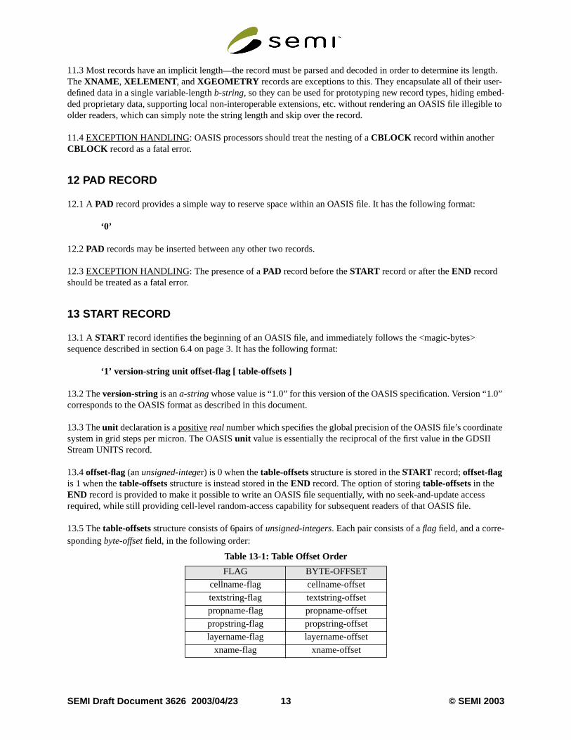
13.5 Thetable-offsetsstructure consists of 6pairs ofunsigned-integers. Each pair consists of aflagfield, and a corre-spondingbyte-offset field, in the following order:
Table 13-1: Table Offset Order
FLAG BYTE-OFFSET
cellname-flag cellname-offset
textstring-flag textstring-offset
propname-flag propname-offset
propstring-flag propstring-offset
layername-flag layername-offset
xname-flag xname-offset
SEMI Draft Document 3626 2003/04/23 13 © SEMI 2003
rst
have
-
mes,
e-
en
on any
l-
D
g val-
13.6 Each of theflagfields is either 1, indicatingstrict mode, or 0, indicatingnon-strictmode, for its respective table.The correspondingbyte-offset field indicates the position of the first record of its respective table relative to the fibyte (byte 0) of the OASIS file. Abyte-offset of 0 indicates the absence of that particular table.
13.7 Innon-strictmode, records of the corresponding type may occur anywhere in the file, even if some of thembeen gathered into a table pointed to by the correspondingbyte-offset.
13.8 Instrict mode,all records of the corresponding type (plus any associatedPROPERTY records) have been gathered into a single contiguous table pointed to by the correspondingbyte-offset. PAD records are also permitted instrict mode tables. In addition,strict modeguarantees that all references to the corresponding class of objects (nastrings, or cells) are made exclusively byreference-number.
13.9 When a givenstrict mode table has been encapsulated within one or moreCBLOCK records, the correspondingbyte-offset should point to the first byte of the firstCBLOCK record containing that table, and the first record of thtable must be the first record which appears after decompression of theCBLOCK record. Adherence to this requirement means that it is not permissible to encapsulate more than onestrict mode table within a singleCBLOCKrecord, nor is it permissible to begin astrict mode table in the middle of aCBLOCK record.
13.10EXCEPTION HANDLING: The absence of aSTART record as the first record in an OASIS file should betreated as a fatal error. A value ofunit which isNaN, Inf, or non-positive, should also be treated as a fatal error. Wha given table offset is nonzero and the table is flagged asstrict, the presence of a “stray” record of that type locateddiscontiguously from its tabular group should be treated as a fatal error, and any records which fail to usereference-numberaccess for that class of objects should be treated as a fatal error. An OASIS reader which does not relyof the record grouping,reference-number, andbyte-offsetguarantees provided bystrict mode is not required to detectand report any exceptions related tostrict mode.
14 END RECORD
14.1 AnEND record identifies the end of the OASIS file. TheEND record must be the last record in the file; no traiing bytes are permitted. It has the following format:
‘2’ [ table-offsets ] padding-string validation-scheme [ validation-signature ]
14.2 The presence of thetable-offsetsstructure is governed byoffset-flagin theSTART record (see section 13). Thepadding-string (ab-string) must be sized and inserted by the OASIS writer so that the total byte length of theENDrecord, including therecord-ID, is exactly 256 bytes. This makes it possible for an OASIS reader to find the ENrecord (and anytable-offsets andvalidation-signature) using a relative seek from the logical end-of-file, avoidingthe need to store a forward pointer in theSTART record. The contents ofpadding-string should be initialized toNUL characters.
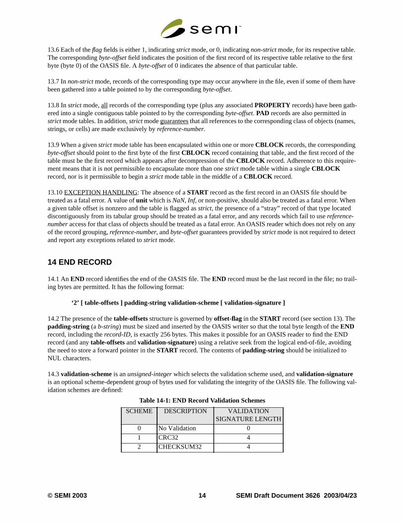
14.3validation-scheme is anunsigned-integer which selects the validation scheme used, andvalidation-signatureis an optional scheme-dependent group of bytes used for validating the integrity of the OASIS file. The followinidation schemes are defined:
Table 14-1: END Record Validation Schemes
SCHEME DESCRIPTION VALIDATIONSIGNATURE LENGTH
0 No Validation 0
1 CRC32 4
2 CHECKSUM32 4
© SEMI 2003 14 SEMI Draft Document 3626 2003/04/23
thee-
of the
ificantis notple C-
fer to
m
-,uld be
14.4 CRC32 Validation
14.4.1 The CRC32 polynomial is specified in ISO 3309:
x32 + x26 + x23 + x22 + x16 + x12 + x11 + x10 + x8 + x7 + x5 + x4 + x2 + x1 + x0
With the left-most bit representing the most significant bit, this corresponds to a value of:
binary 1 0000 0100 1100 0001 0001 1101 1011 0111hexadecimal 104c11db7
14.4.2 The CRC32 value is computed using all of the bytes in the OASIS file from the first byte of theSTART recordto theEND record’svalidation-schemeinteger. It is byte-order dependent. The resulting 32-bit word is stored inlast 4 bytes of the file, with the least significant byte first. This calculation is usually implemented using a tabllookup shift/XOR method. See Appendix 1 for sample C-language source code.
14.5 CHECKSUM32 Validation
14.5.1 The CHECKSUM32 validation signature is computed as a simple unsigned arithmetic summation of allbytes in the OASIS file from the first byte of theSTART record to theEND record’svalidation-schemeinteger. Thisvalue is then truncated to its least significant 32 bits and stored in the last 4 bytes of the file, with the least signbyte first. It is not byte-order dependent, and this characteristic makes it somewhat easier to calculate if the filewritten sequentially. It is, however, far less effective than CRC32 for detecting errors. See Appendix 1 for samlanguage source code.
14.6EXCEPTIONHANDLING: OASIS processors should treat the absence of anEND record in an OASIS file as afatal error.
15 CELLNAME RECORD
15.1 ACELLNAME record associates the name of a cell with a unique reference number. This allowsCELL andPLACEMENT records, if desired, to avoid redundantly storing the actual text of the cell name and instead rethe cell by its assigned reference number. It has the following format:
‘3’ cellname-string‘4’ cellname-string reference-number
15.2cellname-string is ann-stringwhich holds the cell name. Thereference-numberis anunsigned-integerwhichis either implicitly or explicitly assigned to the cell. Implicit assignment occurs in record type ‘3’, by assigningsequential reference numbers beginning with 0 as each successiveCELLNAME record is encountered. Explicitassignment occurs in record type ‘4’.
15.3 Two standard properties,S_BOUNDING_BOX andS_CELL_OFFSET (described in section A2-2 onpage 39), may be associated with eachCELLNAME record. When allCELLNAME records have been grouped intoa single contiguous table instrict mode (as described in section 13 on page 13), with anS_CELL_OFFSET propertyfor everyCELLNAME record, the table forms a complete index of all cells in the OASIS file, suitable for randoaccess.
15.4 Record types ‘3’ and ‘4’ may not both be used in the same OASIS file.
15.5EXCEPTION HANDLING: The appearance of twoCELLNAME records in the same file with the same number but different names, or twoCELLNAME records in the same file with the same name but different numbersshould be treated as a fatal error. The appearance of both record types ‘3’ and ‘4’ in the same OASIS file shotreated as a fatal error. The presence of more than oneS_CELL_OFFSET or S_BOUNDING_BOX property after agivenCELLNAME record should be treated as a fatal error.
SEMI Draft Document 3626 2003/04/23 15 © SEMI 2003

refer-
ing
-should
to the
‘7’,
-,uld be
operty
16 TEXTSTRING RECORD
16.1 ATEXTSTRING record associates a text string with a unique reference number. This allowsTEXT records, ifdesired, to avoid redundantly storing the actual text of the string and instead refer to the string by its assignedence number. It has the following format:
‘5’ text-string‘6’ text-string reference-number
16.2text-string is ana-string which holds the text string. Thereference-number is anunsigned-integer which iseither implicitly or explicitly assigned to the text string. Implicit assignment occurs in record type ‘5’, by assignsequential reference numbers beginning with 0 as each successiveTEXTSTRING record is encountered. Explicitassignment occurs in record type ‘6’.
16.3 Record types ‘5’ and ‘6’ may not both be used in the same OASIS file.
16.4EXCEPTION HANDLING: The appearance of twoTEXTSTRING records in the same file with the samenumber but different names, or twoTEXTSTRING records in the same file with the same name but different numbers, should be treated as a fatal error. The appearance of both record types ‘5’ and ‘6’ in the same OASIS filebe treated as a fatal error.
17 PROPNAME RECORD
17.1 APROPNAME record associates the name of a property with a unique reference number. This allowsPROP-ERTY records, if desired, to avoid redundantly storing the actual text of the property name and instead refer property name by its assigned reference number. It has the following format:
‘7’ propname-string‘8’ propname-string reference-number
17.2propname-string is ann-string which holds the property name. Thereference-number is anunsigned-integerwhich is either implicitly or explicitly assigned to the property name. Implicit assignment occurs in record typeby assigning sequential reference numbers beginning with 0 as each successivePROPNAME record is encountered.Explicit assignment occurs in record type ‘8’.
17.3 Record types ‘7’ and ‘8’ may not both be used in the same OASIS file.
17.4EXCEPTION HANDLING: The appearance of twoPROPNAME records in the same file with the same number but different names, or twoPROPNAME records in the same file with the same name but different numbersshould be treated as a fatal error. The appearance of both record types ‘7’ and ‘8’ in the same OASIS file shotreated as a fatal error.
18 PROPSTRING RECORD
18.1 APROPSTRING record associates a property string with a unique reference number. This allowsPROPERTYrecords, if desired, to avoid redundantly storing the actual text of the property string and instead refer to the prstring by its assigned reference number. It has the following format:
‘9’ prop-string‘10’ prop-string reference-number
© SEMI 2003 16 SEMI Draft Document 3626 2003/04/23
g
begin-0’.
’ in the
bina-
ange of
me is
18.2prop-string is ana-string, b-string , orn-string which holds the property string, depending on the referencinPROPERTY record. Thereference-number is anunsigned-integerwhich is either implicitly or explicitly assignedto the property string. Implicit assignment occurs in record type ‘9’, by assigning sequential reference numbersning with 0 as each successivePROPSTRING record is encountered. Explicit assignment occurs in record type ‘1
18.3 Record types ‘9’ and ‘10’ may not both be used in the same OASIS file.
18.4EXCEPTION HANDLING: The appearance of twoPROPSTRING records in the same file with the samenumber but different names should be treated as a fatal error. The appearance of both record types ‘9’ and ‘10same OASIS file should be treated as a fatal error.
19 LAYERNAME RECORD
19.1 ALAYERNAME record provides a means of mapping numeric (layer,datatype) and (layer,texttype) comtions to layer names. It has the following format:
‘11’ layername-string layer-interval datatype-interval‘12’ layername-string textlayer-interval texttype-interval
19.2 Record type ‘11’ maps a range of (layer,datatype) numbers to a layer name, and record type ‘12’ maps a r(textlayer,texttype) numbers to a layer name.
19.3layername-string is ann-string containing the layer name.
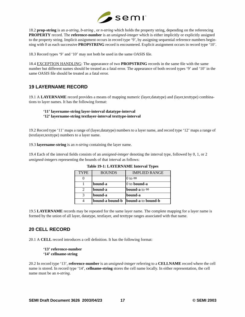
19.4 Each of the interval fields consists of anunsigned-integer denoting the interval type, followed by 0, 1, or 2unsigned-integers representing the bounds of that interval as follows:
19.5LAYERNAME records may be repeated for the same layer name. The complete mapping for a layer naformed by the union of all layer, datatype, textlayer, and texttype ranges associated with that name.
20 CELL RECORD
20.1 ACELL record introduces a cell definition. It has the following format:
‘13’ reference-number‘14’ cellname-string
20.2 In record type ‘13’,reference-numberis anunsigned-integerreferring to aCELLNAME record where the cellname is stored. In record type ‘14’,cellname-string stores the cell name locally. In either representation, the cellname must be ann-string.
Table 19-1: LAYERNAME Interval Types
TYPE BOUNDS IMPLIED RANGE
0 0 to∞1 bound-a 0 tobound-a2 bound-a bound-a to ∞3 bound-a bound-a4 bound-a bound-b bound-a to bound-b
SEMI Draft Document 3626 2003/04/23 17 © SEMI 2003

t
on.
tored
e
It has
20.3 All subsequent records in the file up to the nextCELL , END, or <name>record are considered to be part of thacell.
20.4EXCEPTION HANDLING: Use of areference-number for which there is no correspondingCELLNAMErecord within the same OASIS file should be treated as a fatal error. MultipleCELL records within a single file whichrefer to the same cell name (in effect, a duplicate cell definition) should also be treated as a fatal error.
21 XYABSOLUTE & XYRELATIVE RECORDS
21.1 TheXYABSOLUTE andXYRELATIVE records control the value of modal variablexy-mode, which in turngoverns the interpretation of thex andy values found inPLACEMENT , <geometry>, andTEXT records. They con-sist simply of arecord-ID with no additional fields:
‘15’ = XYABSOLUTE‘16’ = XYRELATIVE
21.2 When eachCELL record is encountered, modal variablexy-mode is set toabsolute, and related modal positionvariablesplacement-x, placement-y, geometry-x, geometry-y, text-x, andtext-y are set to 0. The presence of anXYRELATIVE record forces modal variablexy-mode to relative, and the presence of anXYABSOLUTE recordforces modal variablexy-mode to absolute. This mode may be changed any number of times within a cell definiti
21.3 Inabsolute mode, explicitx andy values, when present, are used directly as the actual (x,y) coordinates.
21.4 Inrelativemode, explicitx andy values, when present, are interpreted as relative displacements from the sposition information in modal variablesplacement-x, placement-y, geometry-x, geometry-y, text-x, or text-y, depend-ing on the record type in which they occur. In this mode, the actual x-coordinate is computed as the sum of thex valueand its corresponding modal position variable, and the actual y-coordinate is computed as the sum of they value andits corresponding modal position variable.
21.5 In bothabsoluteandrelativemodes, when anx or y value is not explicitly present in the record, the value of thcorresponding modal position variable is used for the actual x or y coordinate. In bothabsolute andrelative modes,the corresponding modal position variables are always updated with the actual (x,y) coordinate position.
21.6 The interpretation ofpoint-listsandrepetitionsdoes not depend onabsoluteor relativemode. Also, even when agiven element includes arepetition, the corresponding modal position variables (placement-x, placement-y, geometry-x, geometry-y, text-x, or text-y) are always updated with the actual (x,y) coordinate of the initial element.
22 PLACEMENT RECORD
22.1 APLACEMENT record describes one or more placements of the referenced cell within the current cell. the following format:
‘17’ placement-info-byte [ reference-number | cellname-string ] [ x ] [ y ] [ repetition ]
‘18’ placement-info-byte [ reference-number | cellname-string ] [ magnification ] [ angle ][ x ] [ y ] [ repetition ]
22.2 In record type ‘17’,placement-info-byte contains the bit pattern ‘CNXYRAAF ’.
22.3 In record type ‘18’,placement-info-byte contains the bit pattern ‘CNXYRMAF ’.
© SEMI 2003 18 SEMI Draft Document 3626 2003/04/23
w
s:
lf)errors.
ace-
thes may
22.4 WhenC=1, the cell reference is explicit, in which caseN=1 means thatreference-number (anunsigned-inte-ger) is present, and refers to aCELLNAME record where the cell name is stored;N=0 means thatcellname-string(ann-string) is present and stores the cell name locally. WhenC=0, N is ignored, and the value of modal variableplacement-cell is used, referring to the same cell as the previousPLACEMENT record.
22.5x andy aresigned-integer coordinates representing either theabsolute or therelative (x,y) location of the place-ment.X is 1 if x is present, andY is 1 if y is present. When eitherx or y is unspecified, the value of modal variableplacement-x or placement-y, respectively, is used instead. Refer to section 21 on page 18 for a discussion of hoabsolute andrelative modes affect the interpretation ofx andy.
22.6R is 1 if repetition is present.F=1 indicates reflection (or flip) about the x-axis;F=0 indicates no flip.
22.7 In record type ‘17’, magnification is 1.0 and rotation is a counterclockwise integral multiple of 90 degreeAA=0 for 0 degrees,AA=1 for 90 degrees,AA=2 for 180 degrees, andAA=3 for 270 degrees.
22.8 In record type ‘18’, magnification and rotation are reals;angle is dimensioned in degrees, with positive valuesdenoting a counterclockwise rotation;magnification is, of course, unitless.A is 1 if angle is present, otherwise therotation defaults to 0 degrees.M is 1 if magnification is present, otherwise the magnification defaults to 1.0.
22.9 Each successivePLACEMENT record updates all placement-related modal variables.
22.10EXCEPTION HANDLING: Use of areference-number for which there is no correspondingCELLNAMErecord should be treated as a fatal error. Any recursive cell reference (a cell placing a copy of itself within itseshould be treated as a fatal error. Magnification values which are negative or zero should be treated as fatal Floating point values ofNaNor Inf for either magnification or angle should be treated as fatal errors.PLACEMENTrecords may refer toCELL records regardless of their relative location within the file, and may also refer toexternalcells which are not defined in the same file.
23 PLACEMENT TRANSFORM REPRESENTATION
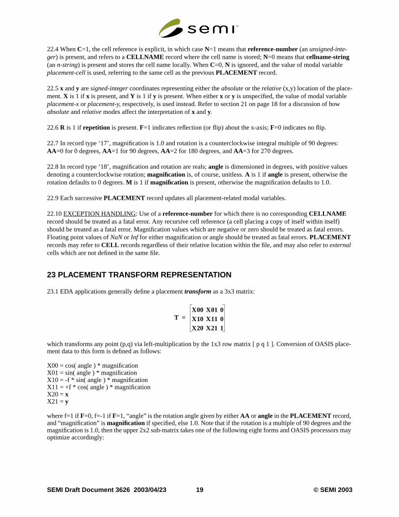
23.1 EDA applications generally define a placementtransform as a 3x3 matrix:
which transforms any point (p,q) via left-multiplication by the 1x3 row matrix [ p q 1 ]. Conversion of OASIS plment data to this form is defined as follows:
X00 = cos( angle ) * magnificationX01 = sin( angle ) * magnificationX10 = -f * sin( angle ) * magnificationX11 = +f * cos( angle ) * magnificationX20 = xX21 = y
where f=1 ifF=0, f=-1 if F=1, “angle” is the rotation angle given by eitherAA or anglein thePLACEMENT record,and “magnification” ismagnification if specified, else 1.0. Note that if the rotation is a multiple of 90 degrees andmagnification is 1.0, then the upper 2x2 sub-matrix takes one of the following eight forms and OASIS processoroptimize accordingly:
TX00 X01 0X10 X11 0X20 X21 1
=
SEMI Draft Document 3626 2003/04/23 19 © SEMI 2003
s-
It has
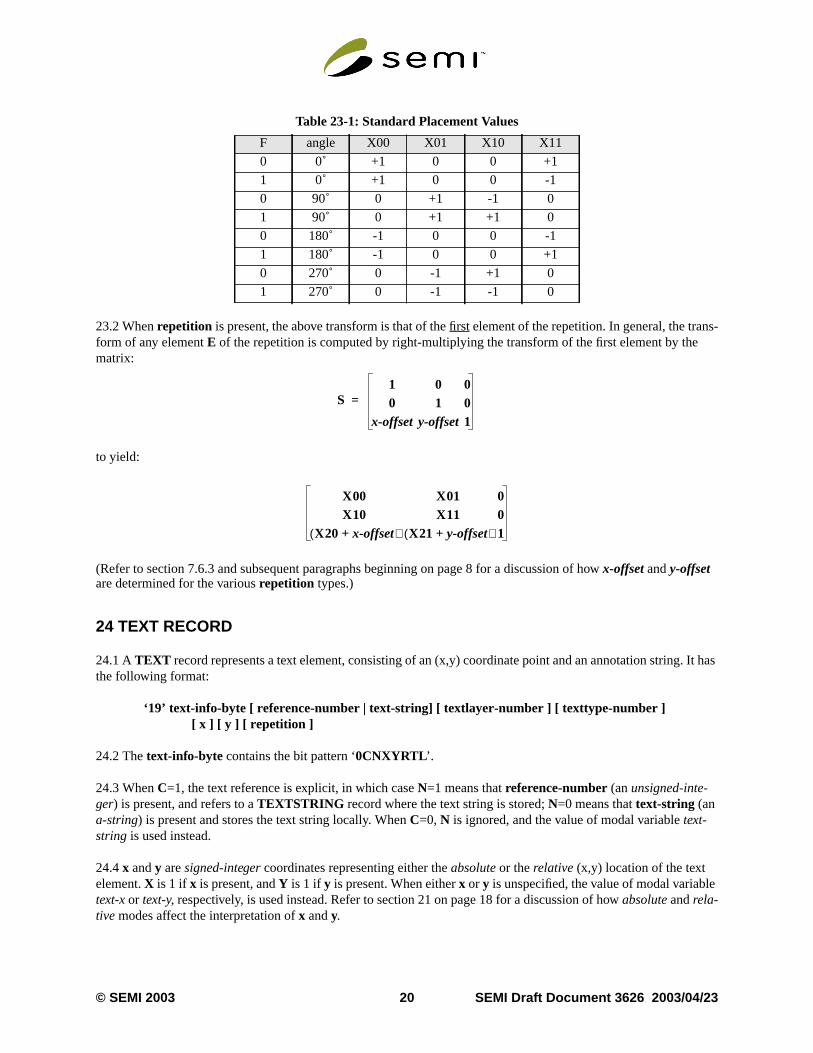
23.2 Whenrepetition is present, the above transform is that of thefirst element of the repetition. In general, the tranform of any elementE of the repetition is computed by right-multiplying the transform of the first element by thematrix:
to yield:
(Refer to section 7.6.3 and subsequent paragraphs beginning on page 8 for a discussion of howx-offset andy-offsetare determined for the variousrepetition types.)
24 TEXT RECORD
24.1 ATEXT record represents a text element, consisting of an (x,y) coordinate point and an annotation string.the following format:
‘19’ text-info-byte [ reference-number | text-string] [ textlayer-number ] [ texttype-number ][ x ] [ y ] [ repetition ]
24.2 Thetext-info-byte contains the bit pattern ‘0CNXYRTL ’.
24.3 WhenC=1, the text reference is explicit, in which caseN=1 means thatreference-number (anunsigned-inte-ger) is present, and refers to aTEXTSTRING record where the text string is stored;N=0 means thattext-string (ana-string) is present and stores the text string locally. WhenC=0, N is ignored, and the value of modal variabletext-string is used instead.
24.4x andy aresigned-integer coordinates representing either theabsolute or therelative (x,y) location of the textelement.X is 1 if x is present, andY is 1 if y is present. When eitherx or y is unspecified, the value of modal variabletext-xor text-y, respectively, is used instead. Refer to section 21 on page 18 for a discussion of howabsoluteandrela-tive modes affect the interpretation ofx andy.
Table 23-1: Standard Placement Values
F angle X00 X01 X10 X11
0 0˚ +1 0 0 +1
1 0˚ +1 0 0 -1
0 90˚ 0 +1 -1 0
1 90˚ 0 +1 +1 0
0 180˚ -1 0 0 -1
1 180˚ -1 0 0 +1
0 270˚ 0 -1 +1 0
1 270˚ 0 -1 -1 0
S1 0 00 1 0
x-offset y-offset1
=
X00 X01 0X10 X11 0
X20 x-offset+( ) X21 y-offset+( ) 1
© SEMI 2003 20 SEMI Draft Document 3626 2003/04/23

as the
f
cus-
e
us-
24.5R is 1 if repetition is present.L is 1 if textlayer-number is present.T is 1 if texttype-number is present. Bothtextlayer-number andtexttype-number areunsigned-integers. Whentextlayer-number and/ortexttype-numberare unspecified, they assume the value of modal variablestextlayer andtexttype, respectively.
24.6 Each successiveTEXT record updates all text-related modal variables.
24.7EXCEPTION HANDLING: Use of areference-number for which there is no correspondingTEXTSTRINGrecord within the same OASIS file should be treated as a fatal error. Implicit use of modal variablestextlayeror text-typewhen they are in the undefined state should be treated as a fatal error.
25 RECTANGLE RECORD
25.1 ARECTANGLE record represents a rectangular figure whose edges are parallel to the x- and y-axes. It hfollowing format:
‘20’ rectangle-info-byte [ layer-number ] [ datatype-number ] [ width ] [ height ] [ x ] [ y ] [ repetition ]
25.2 Therectangle-info-byte contains the bit pattern ‘SWHXYRDL ’.
25.3R is 1 if repetition is present.L is 1 if layer-number is present.D is 1 if datatype-number is present. Bothlayer-number anddatatype-numberareunsigned-integers. Whenlayer-number and/ordatatype-number areunspecified, they assume the value of modal variableslayeranddatatype, respectively.W is 1 if width is present.His 1 if height is present. Bothwidth andheight areunsigned-integers. Whenwidth and/orheight are unspecified,they assume the value of modal variablesgeometry-w andgeometry-h, respectively.
25.4S is 1 if the rectangle is a square. In this case,H mustbe 0, andwidth , if present, is used for both dimensions othe rectangle. Whenwidth is unspecified, the value of modal variablegeometry-w is used instead.
25.5x andy aresigned-integercoordinates representing either theabsoluteor therelative(x,y) location of the lower-left corner of the rectangle.X is 1 if x is present, andY is 1 if y is present. When eitherx or y is unspecified, the valueof modal variablegeometry-xor geometry-y, respectively, is used instead. Refer to section 21 on page 18 for a dission of howabsolute andrelative modes affect the interpretation ofx andy.
25.6 Each successiveRECTANGLE record updates all rectangle-related modal variables. (WhenS=1, bothgeome-try-w andgeometry-h are set to the rectangle’s width.)
25.7EXCEPTION HANDLING: Implicit use of modal variablesgeometry-w, geometry-h, layer,or datatypewhenthey are in the undefined state should be treated as a fatal error. WhenS=1,H=1 should be treated as a fatal error. Thinterpretation of zero-areaRECTANGLE s is application-dependent.
26 POLYGON RECORD
26.1 APOLYGON record represents an arbitrary polygon figure. It has the following format:
‘21’ polygon-info-byte [ layer-number ] [ datatype-number ] [ point-list ] [ x ] [ y ] [ repetition ]
26.2 Thepolygon-info-byte contains the bit pattern ‘00PXYRDL’.
26.3x andy aresigned-integercoordinates representing either theabsoluteor therelative(x,y) location of the initialvertex of the polygon.X is 1 if x is present, andY is 1 if y is present. When eitherx or y is unspecified, the value ofmodal variablegeometry-x or geometry-y, respectively, is used instead. Refer to section 21 on page 18 for a discsion of howabsolute andrelative modes affect the interpretation ofx andy.
SEMI Draft Document 3626 2003/04/23 21 © SEMI 2003
licitasegions
h. It
r a
dalg the
the path
26.4R is 1 if repetition is present.L is 1 if layer-number is present.D is 1 if datatype-number is present. Bothlayer-number anddatatype-numberareunsigned-integers. Whenlayer-number and/ordatatype-number areunspecified, they assume the value of modal variableslayer anddatatype, respectively.
26.5P is 1 if point-list is present. Otherwise, the value of modal variablepolygon-point-list is used. The format ofpoint-lists is defined in section 7.7 on page 9.
26.6 Each successivePOLYGON record updates all polygon-related modal variables.
26.7EXCEPTION HANDLING: Polygons with fewer than three vertices should be treated as fatal errors. Impuse of modal variablespolygon-point-list, layer,or datatypewhen they are in the undefined state should be treateda fatal error. The interpretation of self-intersecting polygons, reentrant polygons, and polygons with zero-area ris application-dependent.
27 PATH RECORD
27.1 APATH record represents an arbitrary path figure, which may be thought of as a polyline with finite widthas the following format:
‘22’ path-info-byte [ layer-number ] [ datatype-number ] [ half-width ][ extension-scheme [ start-extension] [ end-extension ] ] [ point-list ] [ x ] [ y ] [ repetition ]
27.2 Thepath-info-byte contains the bit pattern ‘EWPXYRDL ’.
27.3x andy aresigned-integercoordinates representing either theabsoluteor therelative(x,y) location of the initialvertex of the path centerline.X is 1 if x is present, andY is 1 if y is present. When eitherx or y is unspecified, thevalue of modal variablegeometry-x or geometry-y, respectively, is used instead. Refer to section 21 on page 18 fodiscussion of howabsolute andrelative modes affect the interpretation ofx andy.
27.4R is 1 if repetition is present.L is 1 if layer-number is present.D is 1 if datatype-number is present. Bothlayer-number anddatatype-numberareunsigned-integers. Whenlayer-number and/ordatatype-number areunspecified, they assume the value of modal variableslayer anddatatype, respectively.
27.5P is 1 if point-list is present. Otherwise, the value of modal variablepath-point-listis used. The format ofpoint-lists is defined in section 7.7 on page 9.
27.6W is 1 if half-width (anunsigned-integer) is present; if absent, the half-width value assumes the value of movariablepath-halfwidth. The path is formed by expanding the centerline (represented by line segments connectinpoints) by the half-width value to each side.
27.7E is 1 if extension-scheme is present. Otherwise,extension-scheme, start-extension, andend-extension areabsent, and the values of modal variablespath-start-extension, andpath-end-extension are used instead.
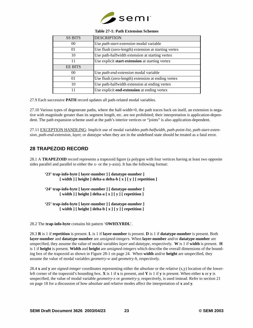
27.8 When present,extension-scheme (anunsigned-integer) contains bit pattern ‘0000SSEE’. TheSS bits governthe path starting extension, and theEE bits govern the path ending extension. Bothstart-extension (present onlywhenSS=‘11’) andend-extension (present only whenEE=‘11’) aresigned-integers, as in GDSII Stream, with posi-tive values causing the path to extend beyond its starting and/or ending vertices, and negative values causingto retract from its starting and/or ending vertices.
© SEMI 2003 22 SEMI Draft Document 3626 2003/04/23
is nega-depen-.
r.
osite
d-
1
27.9 Each successivePATH record updates all path-related modal variables.
27.10 Various types of degenerate paths, where the half-width=0, the path traces back on itself, an extensiontive with magnitude greater than its segment length, etc. are not prohibited; their interpretation is application-dent. The path expansion scheme used at the path’s interior vertices or “joints” is also application-dependent
27.11EXCEPTION HANDLING: Implicit use of modal variablespath-halfwidth, path-point-list, path-start-exten-sion, path-end-extension, layer,or datatypewhen they are in the undefined state should be treated as a fatal erro
28 TRAPEZOID RECORD
28.1 ATRAPEZOID record represents a trapezoid figure (a polygon with four vertices having at least two oppsides parallel and parallel to either the x- or the y-axis). It has the following format:
‘23’ trap-info-byte [ layer-number ] [ datatype-number ][ width ] [ height ] delta-a delta-b [ x ] [ y ] [ repetition ]
‘24’ trap-info-byte [ layer-number ] [ datatype-number ][ width ] [ height ] delta-a [ x ] [ y ] [ repetition ]
‘25’ trap-info-byte [ layer-number ] [ datatype-number ][ width ] [ height ] delta-b [ x ] [ y ] [ repetition ]
28.2 Thetrap-info-byte contains bit pattern ‘OWHXYRDL ’.
28.3R is 1 if repetition is present.L is 1 if layer-number is present.D is 1 if datatype-number is present. Bothlayer-number anddatatype-numberareunsigned-integers. Whenlayer-number and/ordatatype-number areunspecified, they assume the value of modal variableslayeranddatatype, respectively.W is 1 if width is present.His 1 if height is present.Width andheight areunsigned-integerswhich describe the overall dimensions of the bouning box of the trapezoid as shown in Figure 28-1 on page 24. Whenwidth and/orheight are unspecified, theyassume the value of modal variablesgeometry-w andgeometry-h, respectively.
28.4x andy aresigned-integercoordinates representing either theabsoluteor therelative(x,y) location of the lower-left corner of the trapezoid’s bounding box.X is 1 if x is present, andY is 1 if y is present. When eitherx or y isunspecified, the value of modal variablegeometry-x or geometry-y, respectively, is used instead. Refer to section 2on page 18 for a discussion of howabsolute andrelative modes affect the interpretation ofx andy.
Table 27-1: Path Extension Schemes
SS BITS DESCRIPTION
00 Usepath-start-extension modal variable
01 Use flush (zero-length) extension at starting vertex
10 Use path-halfwidth extension at starting vertex
11 Use explicitstart-extension at starting vertex
EE BITS
00 Usepath-end-extension modal variable
01 Use flush (zero-length) extension at ending vertex
10 Use path-halfwidth extension at ending vertex
11 Use explicitend-extension at ending vertex
SEMI Draft Document 3626 2003/04/23 23 © SEMI 2003
this
ase,
S toox,
lication-
paral-as the
f
28.5delta-aanddelta-b are1-deltas, and are both present in record type ‘23’. In record type ‘24’delta-b is assumedto be 0 and is omitted, and in record type ‘25’delta-a is assumed to be 0 and is omitted.
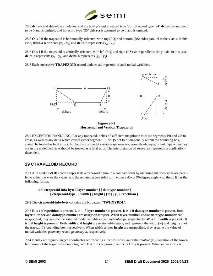
28.6O is 0 if the trapezoid is horizontally-oriented, with top (PQ) and bottom (RS) sides parallel to the x-axis. Incase,delta-a represents (xP - xR) anddelta-b represents (xQ - xS).
28.7O is 1 if the trapezoid is vertically-oriented, with left (PQ) and right (RS) sides parallel to the y-axis. In this cdelta-a represents (yP - yR) anddelta-b represents (yQ - yS).
28.8 Each successiveTRAPEZOID record updates all trapezoid-related modal variables.
Figure 28-1Horizontal and Vertical Trapezoids
28.9EXCEPTION HANDLING: For any trapezoid, deltas of sufficient magnitude to cause segments PR and Qcross, as well as any delta which causes either segment PR or QS not to fit diagonally within the bounding bshould be treated as fatal errors. Implicit use of modal variablesgeometry-w, geometry-h, layer,or datatypewhen theyare in the undefined state should be treated as a fatal error. The interpretation of zero-area trapezoids is appdependent.
29 CTRAPEZOID RECORD
29.1 ACTRAPEZOID record represents a trapezoid figure in a compact form by assuming that two sides arelel to either the x- or the y-axis, and the remaining two sides form either a 45- or 90-degree angle with them. It hfollowing format:
‘26’ ctrapezoid-info-byte [ layer-number ] [ datatype-number ][ ctrapezoid-type ] [ width ] [ height ] [ x ] [ y ] [ repetition ]
29.2 Thectrapezoid-info-byte contains the bit pattern ‘TWHXYRDL ’.
29.3R is 1 if repetition is present.L is 1 if layer-number is present.D is 1 if datatype-number is present. Bothlayer-number anddatatype-numberareunsigned-integers. Whenlayer-number and/ordatatype-number areunspecified, they assume the value of modal variableslayeranddatatype, respectively.W is 1 if width is present.His 1 if height is present. Bothwidth andheight areunsigned-integers, and represent the width (w) and height (h) othe trapezoid’s bounding box, respectively. Whenwidth and/orheight are unspecified, they assume the value ofmodal variablesgeometry-w andgeometry-h, respectively.
29.4x andy aresigned-integercoordinates representing either theabsoluteor therelative(x,y) location of the lower-left corner of the trapezoid’s bounding box.X is 1 if x is present, andY is 1 if y is present. When eitherx or y is
w
w
(x,y)
(x,y)
hh
P Q
R S
Q
R
S
Pdelta-a delta-b
delta
-ade
lta-b
© SEMI 2003 24 SEMI Draft Document 3626 2003/04/23
1
mask
h)(h < 2w)r
oids is
unspecified, the value of modal variablegeometry-x or geometry-y, respectively, is used instead. Refer to section 2on page 18 for a discussion of howabsolute andrelative modes affect the interpretation ofx andy.
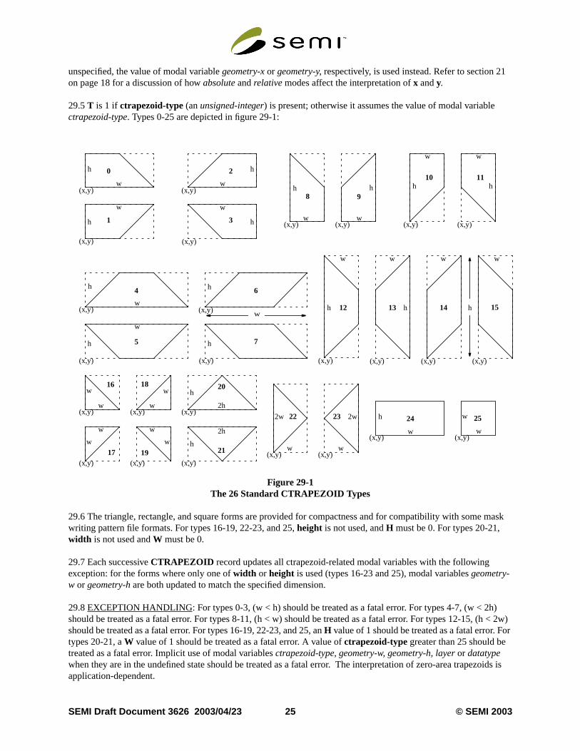
29.5T is 1 if ctrapezoid-type (anunsigned-integer) is present; otherwise it assumes the value of modal variablectrapezoid-type. Types 0-25 are depicted in figure 29-1:
Figure 29-1The 26 Standard CTRAPEZOID Types
29.6 The triangle, rectangle, and square forms are provided for compactness and for compatibility with somewriting pattern file formats. For types 16-19, 22-23, and 25,height is not used, andH must be 0. For types 20-21,width is not used andW must be 0.
29.7 Each successiveCTRAPEZOID record updates all ctrapezoid-related modal variables with the followingexception: for the forms where only one ofwidth or height is used (types 16-23 and 25), modal variablesgeometry-w or geometry-h are both updated to match the specified dimension.
29.8EXCEPTION HANDLING: For types 0-3, (w < h) should be treated as a fatal error. For types 4-7, (w < 2should be treated as a fatal error. For types 8-11, (h < w) should be treated as a fatal error. For types 12-15, should be treated as a fatal error. For types 16-19, 22-23, and 25, anH value of 1 should be treated as a fatal error. Fotypes 20-21, aW value of 1 should be treated as a fatal error. A value ofctrapezoid-type greater than 25 should betreated as a fatal error. Implicit use of modal variablesctrapezoid-type, geometry-w, geometry-h, layeror datatypewhen they are in the undefined state should be treated as a fatal error. The interpretation of zero-area trapezapplication-dependent.
w
w w
w
h
h
h
h
0 2
1 3
(x,y)
(x,y) (x,y)
(x,y)
(x,y)
(x,y) (x,y)
(x,y)
(x,y)(x,y) (x,y) (x,y)
(x,y)(x,y)(x,y) (x,y)
h
h
h
h
hh
hhhh
hw
w
w
ww w w
ww
ww
8 9
10 11
151412 13
6
75
4
(x,y)w
16
(x,y)w
18
(x,y)
w
17(x,y)
w
19
(x,y)
20h
(x,y)
21h
(x,y)
22
w(x,y)
23
w
(x,y)w
25w
(x,y)w
24h
w w
w w
2h
2h
2w 2w
SEMI Draft Document 3626 2003/04/23 25 © SEMI 2003

ptived with
30 CIRCLE RECORD
30.1 ACIRCLE record represents a circular figure. It has the following format:
‘27’ circle-info-byte [ layer-number ] [ datatype-number ] [ radius ] [ x ] [ y ] [ repetition ]
30.2 Thecircle-info-byte contains the bit pattern ‘00rXYRDL ’.
30.3R is 1 if repetition is present.L is 1 if layer-number is present.D is 1 if datatype-number is present. Bothlayer-number anddatatype-numberareunsigned-integers. Whenlayer-number and/ordatatype-number areunspecified, they assume the value of modal variableslayer anddatatype, respectively.
30.4x andy aresigned-integercoordinates representing either theabsoluteor therelative(x,y) location of the circle’scenter.X is 1 if x is present, andY is 1 if y is present. When eitherx or y is unspecified, the value of modal variablegeometry-x or geometry-y, respectively, is used instead. Refer to section 21 on page 18 for a discussion of howabso-lute andrelative modes affect the interpretation ofx andy.
30.4.1r is 1 if radius is present, otherwiseradius assumes the value of modal variablecircle-radius instead.
30.5 Each successiveCIRCLE record updates all circle-related modal variables.
30.6EXCEPTION HANDLING: Implicit use of modal variablescircle-radius, layer,or datatypewhen they are inthe undefined state should be treated as a fatal error. The interpretation of zero-areaCIRCLE s is application-depen-dent.
31 PROPERTY RECORD
31.1 Aproperty is an annotation element consisting of a name plus an optional list of values, supplying descriinformation about the characteristics of the OASIS file or one of its components. A property may be associatethe entire OASIS file, a<name> record, aCELL , aPLACEMENT , or an<element> record within a cell. ThePROPERTY record has the following format:
‘28’ prop-info-byte [ reference-number | propname-string ] [ prop-value-count ] [ <property-value>* ]‘29’
31.2 Record type ‘29’ provides a compact way to specify a duplicate copy of the most-recently-seen propertytogether with its value list. It makes use of modal variableslast-property-name andlast-value-list, which weredefined by a previousPROPERTY record.
31.3 Theprop-info-byte contains the bit pattern ‘UUUUVCNS’.
31.4 WhenC=1, the property name reference is explicit, in which caseN=1 means thatreference-number (anunsigned-integer) is present, and refers to aPROPNAME record where the property name is stored;N=0 means thatpropname-string (ann-string) is present and stores the property name locally. WhenC=0, N is ignored, and thevalue of modal variablelast-property-nameis used instead.
31.5 WhenV=0, values ofUUUU from 0 to 14 indicate the number of<property-value> fields which are part of thisrecord, andprop-value-count is omitted. WhenV=0 andUUUU=15,prop-value-count, anunsigned-integer, ispresent and indicates the number of<property-value> fields. WhenV=1,UUUU must be 0, and modal variablelast-value-list supplies the value list. See section 7.8 on page 11 for a description of<property-value> types.
© SEMI 2003 26 SEMI Draft Document 3626 2003/04/23

oft GDSII-
s
ord
e’ in the
31.6 WhenS=1, a standard property is indicated; whenS=0, a non-standard or user property is indicated. The list OASIS Standard Properties appears in Appendix 2 on page 39. That appendix also describes how to represenStream-style properties using theS_GDS_PROPERTY standard property.
31.7 Each successivePROPERTY record updates modal variableslast-property-name andlast-value-list.
31.8 In general,PROPERTY records directly follow the record with which they are associated.PROPERTYrecords occurring directly after theSTART record are associated globally with the entire OASIS file.PROPERTYrecords occurring after aCELL record or its correspondingCELLNAME record pertain to that entire cell.PROP-ERTY records occurring after aPLACEMENT record pertain to the placement(s) it describes, includingrepetitions.PROPERTY records occurring after an<element> record pertain to that element and anyrepetitions.
31.9PROPERTY records do not associate withCBLOCK or PAD records. Instead, property association occurs athough allCBLOCK records have been uncompressed, and allPAD records have been deleted.
31.10EXCEPTION HANDLING: Implicit use of modal variableslast-property-name or last-value-list when theyare in the undefined state should be treated as a fatal error. Use of areference-number for which there is no corre-spondingPROPNAME record should be treated as a fatal error.
32 XNAME RECORD
32.1 AnXNAME record allows backward-compatible extension of OASIS<name> records. It associates a stringwith a unique reference number. It has the following format:
‘30’ xname-attribute xname-string‘31’ xname-attribute xname-string reference-number
32.2xname-string is user-defined as ana-string, b-string, orn-string which holds the name.xname-attribute is anunsigned-integer providing the ability to associate theXNAME with a user-defined class. Thereference-number isanunsigned-integerwhich is either implicitly or explicitly assigned to the name. Implicit assignment occurs in rectype ‘30’, by assigning sequential reference numbers beginning with 0 as each successiveXNAME record is encoun-tered. Explicit assignment occurs in record type ‘31’.
32.3 Record types ‘30’ and ‘31’ may not both be used in the same OASIS file.
32.4EXCEPTION HANDLING: The appearance of twoXNAME records in the same file with the same referencnumber but different names should be treated as a fatal error. The appearance of both record types ‘30’ and ‘31same OASIS file should be treated as a fatal error.
33 XELEMENT RECORD
33.1 AnXELEMENT record allows backward-compatible extension of OASIS<element> records. It has the fol-lowing format:
‘32’ xelement-attribute xelement-string
33.2xelement-attribute is anunsigned-integer providing the ability to associate theXELEMENT with a user-defined class.xelement-string is ab-string containing user-defined data.
SEMI Draft Document 3626 2003/04/23 27 © SEMI 2003

IS file
n 1.3,
um
IB ver- isses of use.
m-mpliant.ion
34 XGEOMETRY RECORD
34.1 AnXGEOMETRY record allows backward-compatible extension of OASIS<geometry> records. It has thefollowing format:
‘33’ xgeometry-info-byte xgeometry-attribute[ layer-number ] [ datatype-number ] xgeometry-string [ x ] [ y ] [ repetition ]
34.2 Thexgeometry-info-byte contains the bit pattern ‘000XYRDL’.
34.3R is 1 if repetition is present.L is 1 if layer-number is present.D is 1 if datatype-number is present. Bothlayer-number anddatatype-numberareunsigned-integers. Whenlayer-number and/ordatatype-number areunspecified, they assume the value of modal variableslayer anddatatype, respectively.
34.4x andy aresigned-integercoordinates representing either theabsoluteor therelative(x,y) location of the geom-etry.X is 1 if x is present, andY is 1 if y is present. When eitherx or y is unspecified, the value of modal variablegeometry-x or geometry-y, respectively, is used instead. Refer to section 21 on page 18 for a discussion of howabso-lute andrelative modes affect the interpretation ofx andy.
34.5xgeometry-attribute is an integer providing the ability to associate theXGEOMETRY with a user-definedclass.xgeometry-string is ab-string containing user-defined data describing the geometry.
34.6 Each successiveXGEOMETRY record updates allXGEOMETRY -related modal variables.
34.7EXCEPTION HANDLING: Implicit use of modal variableslayer,or datatypewhen they are in the undefinedstate should be treated as a fatal error.
35 CBLOCK RECORD
35.1 ACBLOCK record provides a mechanism for embedding compressed data within the structure of an OASfor additional compactness. It has the following format:
‘34’ comp-type uncomp-byte-count comp-byte-count comp-bytes
35.2comp-type is anunsigned-integerdescribing the type of compression used for this record.uncomp-byte-countis anunsigned-integer describing the number of bytes prior to compression, andcomp-byte-count is anunsigned-integerdescribing the number of bytes after compression.comp-bytes is a sequence of bytes containing the com-pressed byte sequence.
35.3 Whencomp-type=0, the compression scheme is the lossless DEFLATE Compressed Data Format, Versioas documented in RFC 1951 (1996). Other values ofcomp-type are reserved for future versions of the OASIS for-mat; the intent is to be able to support a mixture of compression methods within a single OASIS file for maximcompactness.
35.3.1 One example of compression/decompression software that is compliant with RFC 1951 is found in ZLsion 1.1.4 (March 2002). This software version can be used without any licensing or legal encumbrances. Itexpected that future versions of the ZLIB software will also remain RFC-1951-compliant. Users of future releaZLIB are cautioned to check for continued conformance to RFC 1951 as well as any changes in the terms of
35.3.2 Use of the ZLIB software isnot mandatory in order to be compliant with the OASIS specification. Any copression/decompression software that stores and processes data in conformance with RFC 1951 is OASIS-coIt should be noted that alternatives to theCBLOCK record may emerge in the future, supporting other compressmechanisms. Use of multiple compression methods within a single OASIS file is not ruled out.
© SEMI 2003 28 SEMI Draft Document 3626 2003/04/23

is
r
35.4 TheSTART, END, CELL , and nestedCBLOCK records may not be stored within a compressed record. Thmaintains the ability to perform random access at the cell level within an OASIS file. ACBLOCK record may notencapsulate more than one “strict mode” name table (refer to sections 13 and 14 beginning on page 13). All othesequences of records, of any length, may be stored in aCBLOCK record.
35.5EXCEPTION HANDLING: During the reading of aCBLOCK record, it is a fatal error if the number of bytesreturned after decompression does not matchuncomp-byte-count.
SEMI Draft Document 3626 2003/04/23 29 © SEMI 2003

ollow-
es
36 DETAILED BNF SYNTAX
36.1 This specification uses a modified Backus-Naur Form (BNF) notation to describe OASIS file syntax. The fing table summarizes the conventions used in the modified BNF:
36.2 The OASIS syntax is detailed as follows:
<oasis-file> -> <magic-bytes>START { CBLOCK | PAD | PROPERTY | <cell> | <name> }*END<name> -> {CELLNAME | TEXTSTRING | LAYERNAME | PROPNAME | PROPSTRING | XNAME }<cell> -> { CELL { CBLOCK | PAD | PROPERTY | XYRELATIVE | XYABSOLUTE | <element> }* }<element> -> { <geometry> |PLACEMENT | TEXT | XELEMENT }<geometry> -> {RECTANGLE | POLYGON | PATH | TRAPEZOID | CTRAPEZOID | CIRCLE | XGEOMETRY }
<magic-bytes> -> “%SEMI-OASIS<CR><NL>”
PAD -> ‘0’
START -> ‘1’ <version-string> <unit> <offset-flag> [ <table-offsets> ]
END -> ‘2’ [ <table-offsets> ] <padding-string> <validation-scheme> [ <validation-signature> ]
CELLNAME -> ‘3’ <cellname-string>CELLNAME -> ‘4’ <cellname-string> <reference-number>
TEXTSTRING -> ‘5’ <text-string>TEXTSTRING -> ‘6’ <text-string> <reference-number>
PROPNAME -> ‘7’ <propname-string>PROPNAME -> ‘8’ <propname-string> <reference-number>
PROPSTRING -> ‘9’ <prop-string>PROPSTRING -> ‘10’ <prop-string> <reference-number>
LAYERNAME -> ‘11’ <layername-string> <layer-interval> <datatype-interval>LAYERNAME -> ‘12’ <layername-string> <textlayer-interval> <texttype-interval>
CELL -> ‘13’ <reference-number>CELL -> ‘14’ <cellname-string>
Table 36-1: Modified BNF Notation
SYMBOL TERM MEANING
ABCD Bold Uppercase Denotes an OASIS record name
abcd Bold Lowercase Denotes a fundamental data type defined in section 7
< > Angle Brackets Enclose an element name which is further defined elsewhere in the BNF
-> Arrow Means “is composed of”
[ ] Square BracketsEnclose element(s) which are optional, and if present, occur only once
{ } Braces Enclose element(s) which are required
| Vertical Bar Indicates a choice between mutually exclusive elements within { } braces
* Asterisk An asterisk following an element means the element may occur zero or more tim
... Ellipsis Appears between elements to indicate a variable-length list of like type
‘ ’ Single Quotes Enclose a decimal number denoting an OASISunsigned-integer
“ ” Double Quotes Enclose a literal character string
“<CR>” Control CharacterAngle brackets enclose the name of an ASCII Control Character within a string
// Double Virgule Indicates all characters to its right are comments—not part of the syntax
© SEMI 2003 30 SEMI Draft Document 3626 2003/04/23
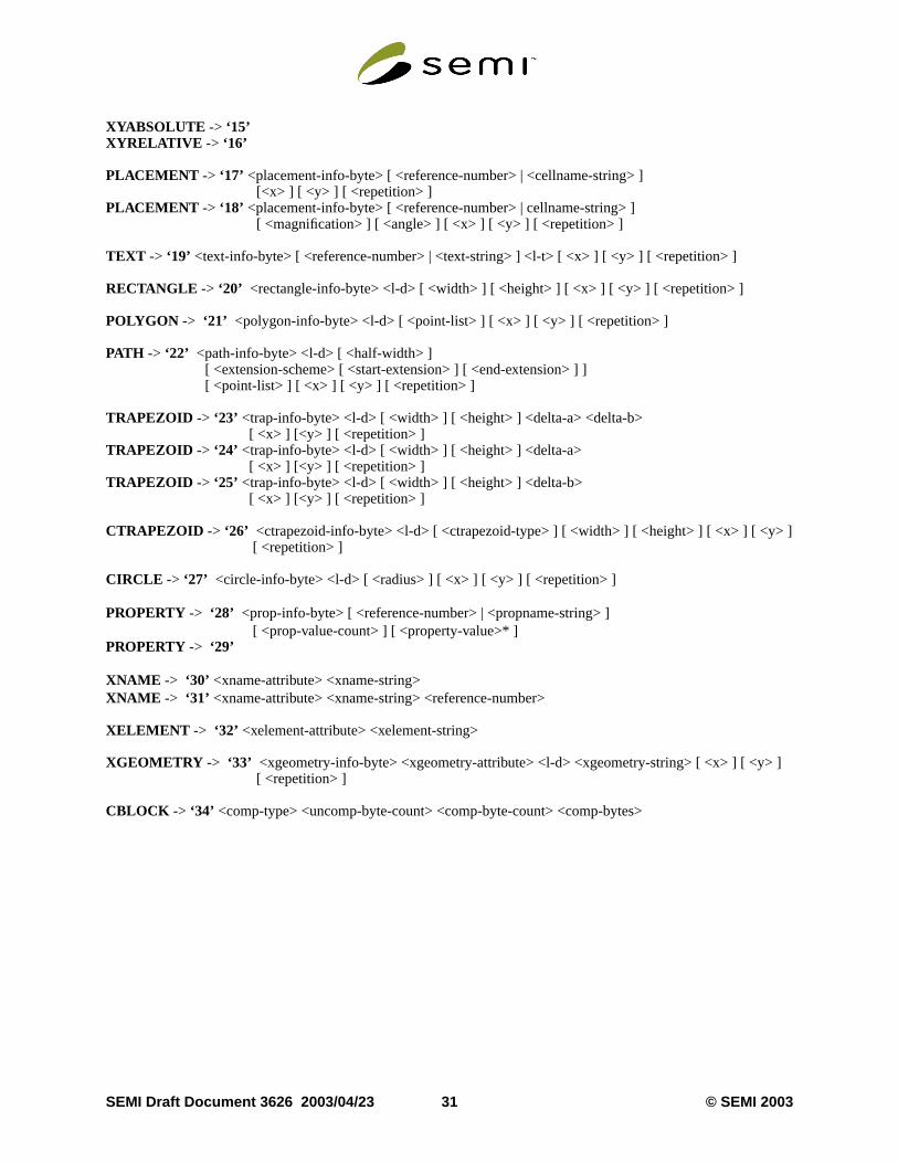
]
]
XYABSOLUTE -> ‘15’XYRELATIVE -> ‘16’
PLACEMENT -> ‘17’ <placement-info-byte> [ <reference-number> | <cellname-string> ] [<x> ] [ <y> ] [ <repetition> ]PLACEMENT -> ‘18’ <placement-info-byte> [ <reference-number> | cellname-string> ] [ <magnification> ] [ <angle> ] [ <x> ] [ <y> ] [ <repetition> ]
TEXT -> ‘19’ <text-info-byte> [ <reference-number> | <text-string> ] <l-t> [ <x> ] [ <y> ] [ <repetition> ]
RECTANGLE -> ‘20’ <rectangle-info-byte> <l-d> [ <width> ] [ <height> ] [ <x> ] [ <y> ] [ <repetition> ]
POLYGON -> ‘21’ <polygon-info-byte> <l-d> [ <point-list> ] [ <x> ] [ <y> ] [ <repetition> ]
PATH -> ‘22’ <path-info-byte> <l-d> [ <half-width> ] [ <extension-scheme> [ <start-extension> ] [ <end-extension> ] ] [ <point-list> ] [ <x> ] [ <y> ] [ <repetition> ]
TRAPEZOID -> ‘23’ <trap-info-byte> <l-d> [ <width> ] [ <height> ] <delta-a> <delta-b> [ <x> ] [<y> ] [ <repetition> ]TRAPEZOID -> ‘24’ <trap-info-byte> <l-d> [ <width> ] [ <height> ] <delta-a> [ <x> ] [<y> ] [ <repetition> ]TRAPEZOID -> ‘25’ <trap-info-byte> <l-d> [ <width> ] [ <height> ] <delta-b> [ <x> ] [<y> ] [ <repetition> ]
CTRAPEZOID -> ‘26’ <ctrapezoid-info-byte> <l-d> [ <ctrapezoid-type> ] [ <width> ] [ <height> ] [ <x> ] [ <y> [ <repetition> ]
CIRCLE -> ‘27’ <circle-info-byte> <l-d> [ <radius> ] [ <x> ] [ <y> ] [ <repetition> ]
PROPERTY -> ‘28’ <prop-info-byte> [ <reference-number> | <propname-string> ] [ <prop-value-count> ] [ <property-value>* ]PROPERTY -> ‘29’
XNAME -> ‘30’ <xname-attribute> <xname-string>XNAME -> ‘31’ <xname-attribute> <xname-string> <reference-number>
XELEMENT -> ‘32’ <xelement-attribute> <xelement-string>
XGEOMETRY -> ‘33’ <xgeometry-info-byte> <xgeometry-attribute> <l-d> <xgeometry-string> [ <x> ] [ <y> [ <repetition> ]
CBLOCK -> ‘34’ <comp-type> <uncomp-byte-count> <comp-byte-count> <comp-bytes>
SEMI Draft Document 3626 2003/04/23 31 © SEMI 2003
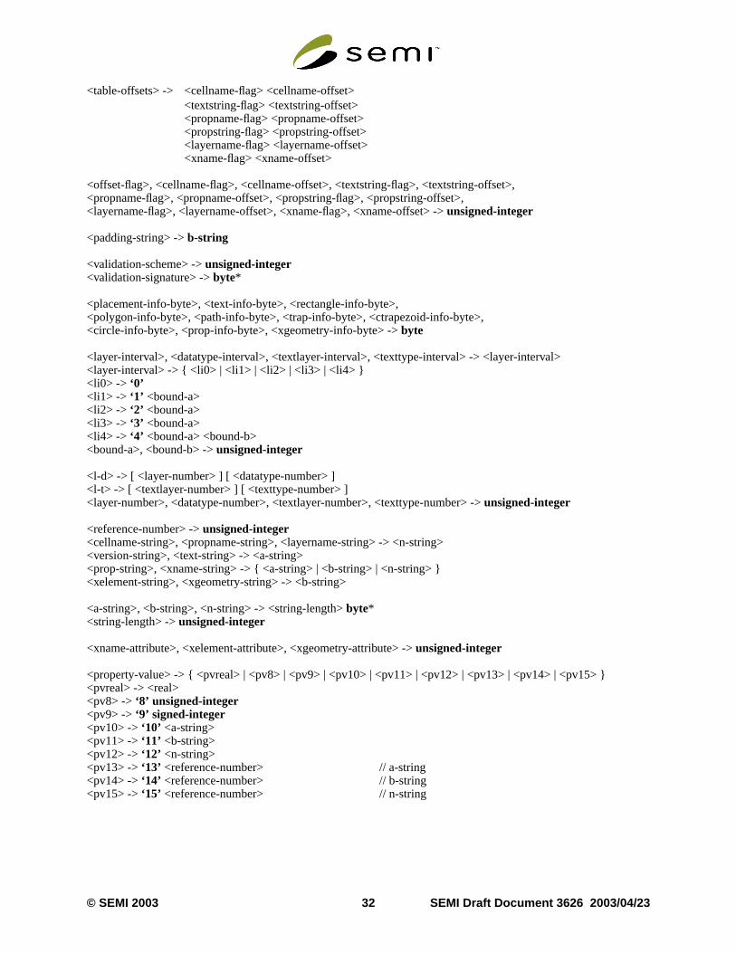
<table-offsets> -> <cellname-flag> <cellname-offset><textstring-flag> <textstring-offset><propname-flag> <propname-offset><propstring-flag> <propstring-offset><layername-flag> <layername-offset><xname-flag> <xname-offset>
<offset-flag>, <cellname-flag>, <cellname-offset>, <textstring-flag>, <textstring-offset>,<propname-flag>, <propname-offset>, <propstring-flag>, <propstring-offset>,<layername-flag>, <layername-offset>, <xname-flag>, <xname-offset> ->unsigned-integer
<padding-string> ->b-string
<validation-scheme> ->unsigned-integer<validation-signature> ->byte*
<placement-info-byte>, <text-info-byte>, <rectangle-info-byte>,<polygon-info-byte>, <path-info-byte>, <trap-info-byte>, <ctrapezoid-info-byte>,<circle-info-byte>, <prop-info-byte>, <xgeometry-info-byte> ->byte
<layer-interval>, <datatype-interval>, <textlayer-interval>, <texttype-interval> -> <layer-interval><layer-interval> -> { <li0> | <li1> | <li2> | <li3> | <li4> }<li0> -> ‘0’<li1> -> ‘1’ <bound-a><li2> -> ‘2’ <bound-a><li3> -> ‘3’ <bound-a><li4> -> ‘4’ <bound-a> <bound-b><bound-a>, <bound-b> ->unsigned-integer
<l-d> -> [ <layer-number> ] [ <datatype-number> ]<l-t> -> [ <textlayer-number> ] [ <texttype-number> ]<layer-number>, <datatype-number>, <textlayer-number>, <texttype-number> ->unsigned-integer
<reference-number> ->unsigned-integer<cellname-string>, <propname-string>, <layername-string> -> <n-string><version-string>, <text-string> -> <a-string><prop-string>, <xname-string> -> { <a-string> | <b-string> | <n-string> }<xelement-string>, <xgeometry-string> -> <b-string>
<a-string>, <b-string>, <n-string> -> <string-length>byte*<string-length> ->unsigned-integer
<xname-attribute>, <xelement-attribute>, <xgeometry-attribute> -> unsigned-integer
<property-value> -> { <pvreal> | <pv8> | <pv9> | <pv10> | <pv11> | <pv12> | <pv13> | <pv14> | <pv15> }<pvreal> -> <real><pv8> ->‘8’ unsigned-integer<pv9> ->‘9’ signed-integer<pv10> ->‘10’ <a-string><pv11> ->‘11’ <b-string><pv12> ->‘12’ <n-string><pv13> ->‘13’ <reference-number> // a-string<pv14> ->‘14’ <reference-number> // b-string<pv15> ->‘15’ <reference-number> // n-string
© SEMI 2003 32 SEMI Draft Document 3626 2003/04/23
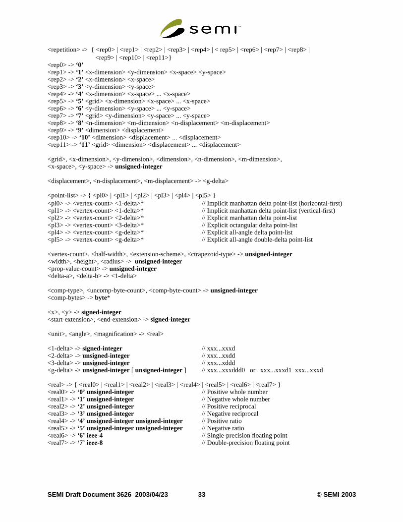
<repetition> -> { <rep0> | <rep1> | <rep2> | <rep3> | <rep4> | < rep5> | <rep6> | <rep7> | <rep8> | <rep9> | <rep10> | <rep11>}<rep0> ->‘0’<rep1> ->‘1’ <x-dimension> <y-dimension> <x-space> <y-space><rep2> ->‘2’ <x-dimension> <x-space><rep3> ->‘3’ <y-dimension> <y-space><rep4> ->‘4’ <x-dimension> <x-space> ... <x-space><rep5> ->‘5’ <grid> <x-dimension> <x-space> ... <x-space><rep6> ->‘6’ <y-dimension> <y-space> ... <y-space><rep7> ->‘7’ <grid> <y-dimension> <y-space> ... <y-space><rep8> ->‘8’ <n-dimension> <m-dimension> <n-displacement> <m-displacement><rep9> ->‘9’ <dimension> <displacement><rep10> ->‘10’ <dimension> <displacement> ... <displacement><rep11> ->‘11’ <grid> <dimension> <displacement> ... <displacement>
<grid>, <x-dimension>, <y-dimension>, <dimension>, <n-dimension>, <m-dimension>,<x-space>, <y-space> ->unsigned-integer
<displacement>, <n-displacement>, <m-displacement> -> <g-delta>
<point-list> -> { <pl0> | <pl1> | <pl2> | <pl3> | <pl4> | <pl5> }<pl0> -> <vertex-count> <1-delta>* // Implicit manhattan delta point-list (horizontal-first)<pl1> -> <vertex-count> <1-delta>* // Implicit manhattan delta point-list (vertical-first)<pl2> -> <vertex-count> <2-delta>* // Explicit manhattan delta point-list<pl3> -> <vertex-count> <3-delta>* // Explicit octangular delta point-list<pl4> -> <vertex-count> <g-delta>* // Explicit all-angle delta point-list<pl5> -> <vertex-count> <g-delta>* // Explicit all-angle double-delta point-list
<vertex-count>, <half-width>, <extension-scheme>, <ctrapezoid-type> ->unsigned-integer<width>, <height>, <radius> ->unsigned-integer<prop-value-count> ->unsigned-integer<delta-a>, <delta-b> -> <1-delta>
<comp-type>, <uncomp-byte-count>, <comp-byte-count> ->unsigned-integer<comp-bytes> ->byte*
<x>, <y> ->signed-integer<start-extension>, <end-extension> ->signed-integer
<unit>, <angle>, <magnification> -> <real>
<1-delta> -> signed-integer // xxx...xxxd<2-delta> -> unsigned-integer // xxx...xxdd<3-delta> ->unsigned-integer // xxx...xddd<g-delta> -> unsigned-integer [ unsigned-integer ] // xxx...xxxddd0 or xxx...xxxd1 xxx...xxxd
<real> -> { <real0> | <real1> | <real2> | <real3> | <real4> | <real5> | <real6> | <real7> }<real0> ->‘0’ unsigned-integer // Positive whole number<real1> ->‘1’ unsigned-integer // Negative whole number<real2> ->‘2’ unsigned-integer // Positive reciprocal<real3> ->‘3’ unsigned-integer // Negative reciprocal<real4> ->‘4’ unsigned-integer unsigned-integer // Positive ratio<real5> ->‘5’ unsigned-integer unsigned-integer // Negative ratio<real6> ->‘6’ ieee-4 // Single-precision floating point<real7> ->‘7’ ieee-8 // Double-precision floating point
SEMI Draft Document 3626 2003/04/23 33 © SEMI 2003
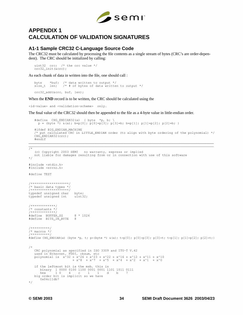
depen-
APPENDIX 1CALCULATION OF VALIDATION SIGNATURES
A1-1 Sample CRC32 C-Language Source CodeThe CRC32 must be calculated by processing the file contents as a single stream of bytes (CRC’s are order-dent). The CRC should be initialized by calling:
uint32 crc; /* the crc value */ crc32_init(&crc);
As each chunk of data in written into the file, one should call :
byte *buf; /* data written to output */ size_t len; /* # of bytes of data written to output */
crc32_add(&crc, buf, len);
When theEND record is to be written, the CRC should be calculated using the
<id-value> and <validation-scheme> only.
The final value of the CRC32 should then be appended to the file as a 4-byte value in little-endian order.
#define CHG_ENDIAN32(a) { byte *p, b; \ p = (byte *) &(a); b=p[0]; p[0]=p[3]; p[3]=b; b=p[1]; p[1]=p[2]; p[2]=b; }
#ifdef BIG_ENDIAN_MACHINE/* put calculated CRC in LITTLE_ENDIAN order (to align with byte ordering of the polynomial) */
CHG_ENDIAN32(crc); #endif__________________________________________________________________________________________________________________________________________________________________________________________________/* (c) Copyright 2003 SEMI no warranty, express or implied not liable for damages resulting from or in connection with use of this software*/
#include <stdio.h>#include <errno.h>
#define TEST
/********************//* basic data types *//********************/typedef unsigned char byte;typedef unsigned int uint32;
/*************//* constants *//*************/#define BUFFER_SZ 8 * 1024#define BITS_IN_BYTE 8
/**********//* macros *//**********/#define CHG_ENDIAN(a) {byte *p, t; p=(byte *) &(a); t=p[0]; p[0]=p[3]; p[3]=t; t=p[1]; p[1]=p[2]; p[2]=t;}
/* CRC polynomial as specified in ISO 3309 and ITU-T V.42 used in Ethernet, FDDI, cksum, etc polynomial is x^32 + x^26 + x^23 + x^22 + x^16 + x^12 + x^11 + x^10 + x^8 + x^7 + x^5 + x^4 + x^2 + x^1 + x^0
if the leftmost bit is the msb, this is binary 1 0000 0100 1100 0001 0001 1101 1011 0111 hex 1 0 4 c 1 1 d b 7 big order bit is implicit so we have 0x04c11db7*/
© SEMI 2003 34 SEMI Draft Document 3626 2003/04/23
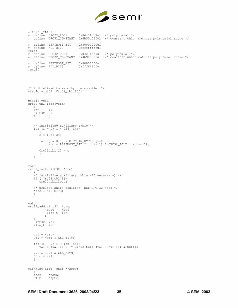
#ifdef _ILP32# define CRC32_POLY 0x04c11db7ul /* polynomial */# define CRC32_CONSTANT 0x4b90b035ul /* constant which matches polynomial above */
# define LEFTMOST_BIT 0x80000000ul# define ALL_BITS 0xfffffffful#else# define CRC32_POLY 0x04c11db7u /* polynomial */# define CRC32_CONSTANT 0x4b90b035u /* constant which matches polynomial above */
# define LEFTMOST_BIT 0x80000000u# define ALL_BITS 0xffffffffu#endif
/* initialized to zero by the compiler */static uint32 Crc32_tbl[256];
static voidcrc32_tbl_load(void) { int i; uint32 c; int j;
/* initialize auxiliary table */ for (i = 0; i < 256; i++) { c = i << 24;
for (j = 0; j < BITS_IN_BYTE; j++) c = c & LEFTMOST_BIT ? (c << 1) ^ CRC32_POLY : (c << 1);
Crc32_tbl[i] = c; } }
voidcrc32_init(uint32 *crc) { /* initialize auxiliary table (if necessary) */ if (!Crc32_tbl[1]) crc32_tbl_load();
/* preload shift register, per CRC-32 spec */ *crc = ALL_BITS; }
voidcrc32_add(uint32 *crc, byte *buf, size_t len ) { uint32 val; size_t i;
val = *crc; val = ~val & ALL_BITS;
for (i = 0; i < len; i++) val = (val >> 8) ^ Crc32_tbl[ (val ^ buf[i]) & 0xff];
val = ~val & ALL_BITS; *crc = val; }
main(int argc, char **argv) { char *path; FILE *fptr;
SEMI Draft Document 3626 2003/04/23 35 © SEMI 2003
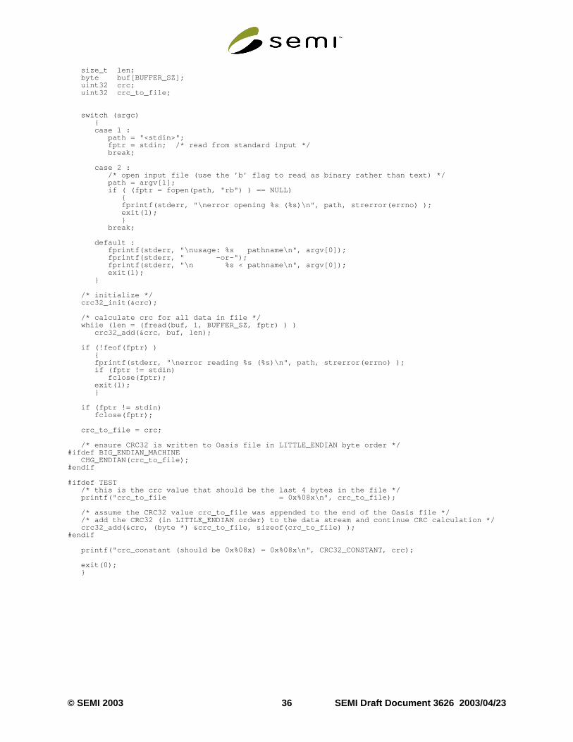
size_t len; byte buf[BUFFER_SZ]; uint32 crc; uint32 crc_to_file;
switch (argc) { case 1 : path = "<stdin>"; fptr = stdin; /* read from standard input */ break;
case 2 : /* open input file (use the ’b’ flag to read as binary rather than text) */ path = argv[1]; if ( (fptr = fopen(path, "rb") ) == NULL) { fprintf(stderr, "\nerror opening %s (%s)\n", path, strerror(errno) ); exit(1); } break;
default : fprintf(stderr, "\nusage: %s pathname\n", argv[0]); fprintf(stderr, " -or-"); fprintf(stderr, "\n %s < pathname\n", argv[0]); exit(1); }
/* initialize */ crc32_init(&crc);
/* calculate crc for all data in file */ while (len = (fread(buf, 1, BUFFER_SZ, fptr) ) ) crc32_add(&crc, buf, len);
if (!feof(fptr) ) { fprintf(stderr, "\nerror reading %s (%s)\n", path, strerror(errno) ); if (fptr != stdin) fclose(fptr); exit(1); }
if (fptr != stdin) fclose(fptr);
crc_to_file = crc;
/* ensure CRC32 is written to Oasis file in LITTLE_ENDIAN byte order */#ifdef BIG_ENDIAN_MACHINE CHG_ENDIAN(crc_to_file);#endif
#ifdef TEST /* this is the crc value that should be the last 4 bytes in the file */ printf("crc_to_file = 0x%08x\n", crc_to_file);
/* assume the CRC32 value crc_to_file was appended to the end of the Oasis file */ /* add the CRC32 (in LITTLE_ENDIAN order) to the data stream and continue CRC calculation */ crc32_add(&crc, (byte *) &crc_to_file, sizeof(crc_to_file) );#endif
printf("crc_constant (should be 0x%08x) = 0x%08x\n", CRC32_CONSTANT, crc);
exit(0); }
© SEMI 2003 36 SEMI Draft Document 3626 2003/04/23
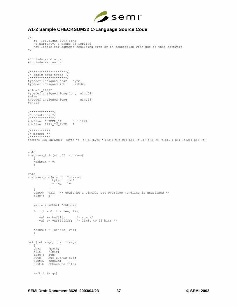
A1-2 Sample CHECKSUM32 C-Language Source Code
/* (c) Copyright 2003 SEMI no warranty, express or implied not liable for damages resulting from or in connection with use of this software*/
#include <stdio.h>#include <errno.h>
/********************//* basic data types *//********************/typedef unsigned char byte;typedef unsigned int uint32;
#ifdef _ILP32typedef unsigned long long uint64;#elsetypedef unsigned long uint64;#endif
/*************//* constants *//*************/#define BUFFER_SZ 8 * 1024#define BITS_IN_BYTE 8
/**********//* macros *//**********/#define CHG_ENDIAN(a) {byte *p, t; p=(byte *)&(a); t=p[0]; p[0]=p[3]; p[3]=t; t=p[1]; p[1]=p[2]; p[2]=t;}
voidchecksum_init(uint32 *chksum) { *chksum = 0; }
voidchecksum_add(uint32 *chksum, byte *buf, size_t len ) { uint64 val; /* could be a uint32, but overflow handling is undefined */ size_t i;
val = (uint64) *chksum;
for (i = 0; i < len; i++) { val += buf[i]; /* sum */ val &= 0xffffffff; /* limit to 32 bits */ }
*chksum = (uint32) val; }
main(int argc, char **argv) { char *path; FILE *fptr; size_t len; byte buf[BUFFER_SZ]; uint32 chksum; uint32 chksum_to_file;
switch (argc) {
SEMI Draft Document 3626 2003/04/23 37 © SEMI 2003
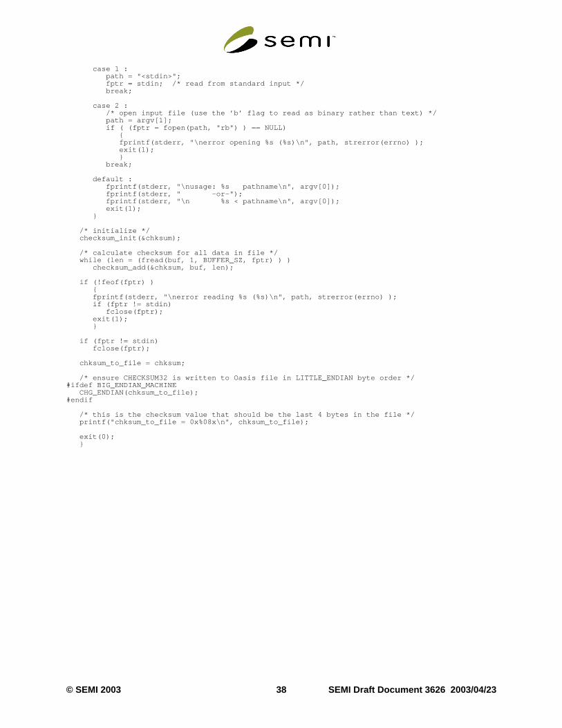
case 1 : path = "<stdin>"; fptr = stdin; /* read from standard input */ break;
case 2 : /* open input file (use the ’b’ flag to read as binary rather than text) */ path = argv[1]; if ( (fptr = fopen(path, "rb") ) == NULL) { fprintf(stderr, "\nerror opening %s (%s)\n", path, strerror(errno) ); exit(1); } break;
default : fprintf(stderr, "\nusage: %s pathname\n", argv[0]); fprintf(stderr, " -or-"); fprintf(stderr, "\n %s < pathname\n", argv[0]); exit(1); }
/* initialize */ checksum_init(&chksum);
/* calculate checksum for all data in file */ while (len = (fread(buf, 1, BUFFER_SZ, fptr) ) ) checksum_add(&chksum, buf, len);
if (!feof(fptr) ) { fprintf(stderr, "\nerror reading %s (%s)\n", path, strerror(errno) ); if (fptr != stdin) fclose(fptr); exit(1); }
if (fptr != stdin) fclose(fptr);
chksum_to_file = chksum;
/* ensure CHECKSUM32 is written to Oasis file in LITTLE_ENDIAN byte order */#ifdef BIG_ENDIAN_MACHINE CHG_ENDIAN(chksum_to_file);#endif
/* this is the checksum value that should be the last 4 bytes in the file */ printf("chksum_to_file = 0x%08x\n", chksum_to_file);
exit(0); }
© SEMI 2003 38 SEMI Draft Document 3626 2003/04/23

list con-
ists of
y
sts of
rs.
d. an
APPENDIX 2OASIS Standard Properties
A2-1 File-Level Standard Properties
A2-1.1 Any file-level standard properties must appear immediately after theSTART record in an OASIS file. Use offile-level standard properties is optional—OASIS processors may omit/ignore any or all of them.
A2-1.2S_MAX_SIGNED_INTEGER_WIDTHThis property declares the maximum number of bytes required to represent anysigned-integer in the file, after allcontinuation bits have been removed and the integer has been expressed in twos-complement form. Its valuesists of a singleunsigned-integer.
A2-1.3S_MAX_UNSIGNED_INTEGER_WIDTHThis property declares the maximum number of bytes required to represent anyunsigned-integer in the file, after allcontinuation bits have been removed. Its value list consists of a singleunsigned-integer.
A2-1.4S_MAX_STRING_LENGTHThis property declares the maximum number of bytes permitted in any string within the file. Its value list consa singleunsigned-integer.
A2-1.5S_POLYGON_MAX_VERTICESThis property declares the maximum number of vertices permitted in any polygon within the file, including animplicit vertices, but counting the initial vertex only once. Its value list consists of a singleunsigned-integer.
A2-1.6S_PATH_MAX_VERTICESThis property declares the maximum number of vertices permitted in any path within the file. Its value list consia singleunsigned-integer.
A2-1.7S_TOP_CELLThis property is used to declare the name of the “top cell” of a cell hierarchy. Its value list consists of a singlen-string. It may be repeated if more than one distinct cell hierarchy exists within the OASIS file in which it appea
A2-1.8S_BOUNDING_BOXES_AVAILABLEThis property indicates whether or not S_BOUNDING_BOX properties appear inCELLNAME records. Its valuelist consists of a singleunsigned-integer. A value of 0 means that S_BOUNDING_BOX properties are not provideA value of 1 means that at least some S_BOUNDING_BOX properties are provided. A value of 2 means thatS_BOUNDING_BOX property is provided for everyCELLNAME record.
SEMI Draft Document 3626 2003/04/23 39 © SEMI 2003
all of
end
oxll and
ng
imesn
A2-2 Cell-Level Standard Properties
A2-2.1 Any cell-level standard properties must appear immediately after the correspondingCELLNAME record inan OASIS file. Use of cell-level standard properties is optional—OASIS processors may omit/ignore any orthem.
A2-2.2S_BOUNDING_BOXThis property may occur once after eachCELLNAME record, and declares the bounding box of that cell. Its valulist consists of the following 5 fields: <flags> <lower-left-x> <lower-left-y> <width> <height>. The lower-left-x alower-left-y fields aresigned-integers representing the lower-left corner of the cell’s bounding box. The width andheight fields areunsigned-integers representing the width and height of the cell’s bounding box. The bounding bshould be calculated to cover the full extent of all geometric figures and text element (x,y) points within that ceall of its subcells after a full expansion of any hierarchy beneath the cell.
The flags field is anunsigned-integer. Only the least-significant 3 bits are presently defined, and have the followimeanings:
flags.bit.0: 0 = bounding box is known1 = bounding box is unknown
flags.bit.1: 0 = bounding box is non-empty1 = bounding box is empty
flags.bit.2: 0 = bounding box depends on no external cells1 = bounding box depends on one or more external cells
A2-2.3S_CELL_OFFSETThis property may occur once after eachCELLNAME record. Its value list consists of a singleunsigned-integerwhich declares the byte offset from the beginning of the file (byte 0) to where the correspondingCELL recordappears in the file. An offset value of 0 denotes anexternal cell, with no correspondingCELL record in the sameOASIS file.
A2-3 Element-Level Properties
A2-3.1S_GDS_PROPERTYThis property is intended exclusively for compatibility with GDSII Stream properties. It may occur one or more tafter any element within aCELL definition. Its value list contains exactly two values in sequence: <attribute>, aunsigned-integer, and <propvalue-string>, ab-string. These values correspond to GDSII Stream PROPATTR andPROPVALUE records, respectively.
© SEMI 2003 40 SEMI Draft Document 3626 2003/04/23

for anyr.
levant lit-thout
ons stan- and the
s in
NOTICE : SEMI makes no warranties or representations as to the suitability of the standards set forth herein particular application. The determination of the suitability of the standard is solely the responsibility of the useUsers are cautioned to refer to manufacturer’s instructions, product labels, product data sheets, and other reerature, respecting any materials or equipment mentioned herein. These standards are subject to change winotice.
By publication of this standard, Semiconductor Equipment and Materials International (SEMI) takes no positirespecting the validity of any patent rights or copyrights asserted in connection with any items mentioned in thidard. Users of this standard are expressly advised that determination of any such patent rights or copyrights,risk of infringement of such rights are entirely their own responsibility.
Copyright © SEMI® (Semiconductor Equipment and Materials Interna-tional), 3081 Zanker Road, San Jose, CA 95134. Reproduction of the contentwhole or in part is forbidden without express written consent of SEMI.
SEMI Draft Document 3626 2003/04/23 4
1 © SEMI 2003