Embed Size (px)
Citation preview
2332 IEEE TRANSACTIONS ON MAGNETICS, VOL. 44, NO. 10, OCTOBER 2008
Object-Oriented Knowledge-Based System for DistributionTransformer Design
C. Hernandez1, M. A. Arjona1, and Shi-Hai Dong2
Electrical and Electronic Engineering Department, Instituto Tecnológico de La Laguna, 28268 Torreón, Coahuila, MéxicoPhysics Department, Instituto Politécnico Nacional, México, DF 07738, México
The first stage in any machine design process involves a substantial heuristic exercise to select the machine best suited to a set ofspecifications. The second stage obtains the dimensions of a selected machine and a design that satisfies specifications. The final stageusually involves optimization and the finite-element method. We present an object-oriented knowledge-based system for distributiontransformer design with the first two stages fully automated. We describe the rationale for the system, the architectural design procedure,and the approach taken in constructing the system for practical applications.
Index Terms—Expert system, knowledge, optimization, transformer.
I. INTRODUCTION
TRANSFORMER manufacturers have a particular need tocomputerize their design procedure in order to save engi-
neering-design man-hours, increase design capacity, reduce thedelivery cycle, and optimize the use of material. This is par-ticularly true in times where the reduction in fabrication costsand the payment of specialized personnel salaries may definethe survival of a small factory. Numerical techniques are pow-erful tools that help the engineer in his design task. Most man-ufacturers use finite-element (FE) models offline for checkingthe transformer performance. However, one disadvantage of theFE approach is its computation time. Therefore, a need for anenvironment that combines the expertise of manufacturers andadvanced numerical techniques has been detected [1], [2].
Expert systems have been successfully used in manyengineering areas [3], [4]. Application to the design ofswitched-mode power supplies has been reported in literature,where the knowledge-based system has been used to improve adesign and/or to select the most suited components [5]. How-ever, a power or distribution transformer differs from a smallpower magnetic component in the sense that it has differentperformance indicators, higher voltages, and currents alongwith higher cost. Few attempts have been made to implementa design environment for distribution transformers, which maybe due to the fact that most heuristic knowledge is in the handsof manufacturers [6].
In this paper, a detailed implementation of an object-orientedknowledge-based system (OOKBS) for designing distributiontransformers is presented. This system is part of a designenvironment under development. The OOKBS consists oftwo expert systems; the first one determines the transformerspecification based on the application of the transformer. Thepaper’s contribution consists of the development of a secondexpert system that determines a transformer design based on
Digital Object Identifier 10.1109/TMAG.2008.2001483
the expertise and design knowledge of a manufacturer. Designand software development results are presented.
II. DESIGN PROCESS
A. System Architecture
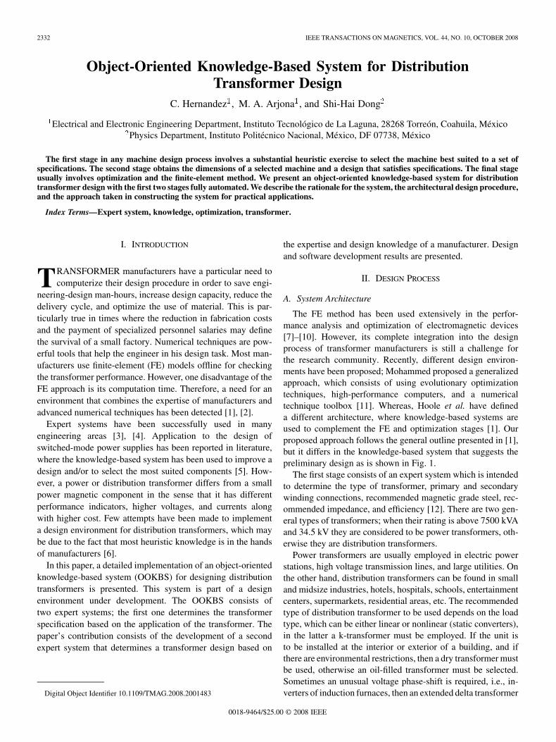
The FE method has been used extensively in the perfor-mance analysis and optimization of electromagnetic devices[7]–[10]. However, its complete integration into the designprocess of transformer manufacturers is still a challenge forthe research community. Recently, different design environ-ments have been proposed; Mohammed proposed a generalizedapproach, which consists of using evolutionary optimizationtechniques, high-performance computers, and a numericaltechnique toolbox [11]. Whereas, Hoole et al. have defineda different architecture, where knowledge-based systems areused to complement the FE and optimization stages [1]. Ourproposed approach follows the general outline presented in [1],but it differs in the knowledge-based system that suggests thepreliminary design as is shown in Fig. 1.
The first stage consists of an expert system which is intendedto determine the type of transformer, primary and secondarywinding connections, recommended magnetic grade steel, rec-ommended impedance, and efficiency [12]. There are two gen-eral types of transformers; when their rating is above 7500 kVAand 34.5 kV they are considered to be power transformers, oth-erwise they are distribution transformers.
Power transformers are usually employed in electric powerstations, high voltage transmission lines, and large utilities. Onthe other hand, distribution transformers can be found in smalland midsize industries, hotels, hospitals, schools, entertainmentcenters, supermarkets, residential areas, etc. The recommendedtype of distribution transformer to be used depends on the loadtype, which can be either linear or nonlinear (static converters),in the latter a k-transformer must be employed. If the unit isto be installed at the interior or exterior of a building, and ifthere are environmental restrictions, then a dry transformer mustbe used, otherwise an oil-filled transformer must be selected.Sometimes an unusual voltage phase-shift is required, i.e., in-verters of induction furnaces, then an extended delta transformer
0018-9464/$25.00 © 2008 IEEE
HERNANDEZ et al.: OBJECT-ORIENTED KNOWLEDGE-BASED SYSTEM FOR DISTRIBUTION TRANSFORMER DESIGN 2333
Fig. 1. System architecture.
must be designed. The winding connection, delta or star, de-pends on neutral wire availability. Other knowledge of the ex-pert design engineer is included such as: if low no-load lossesare desired, then amorphous or better grade steel must be se-lected. The output of this stage gives the design specification ofthe transformer, such as the rating, winding voltages and con-nections, frequency, magnetic steel, as well as winding material(copper or aluminum). Furthermore, it also yields the recom-mended impedance, efficiency, and excitation current to avoidcost penalties imposed by the transformer buyer.
The purpose of the second expert system is to determinea design based on the specification given by the first expertsystem. The OOKBS uses structural, analytical, graphical,procedural, and heuristics, which closely mimics the engineer’sexpertise. This stage yields a design that fulfills the designspecifications, which is the engineer’s goal. By using the coregeometry, winding data, electrical clearances, and magneticmaterial information (specific iron loss and magnetizing powerand BH data), a finite-element analysis (FEA) can then becarried out to check the expected performance. In case thedesign results are not satisfactory, then an optimization processor FE final tuning can be carried out; this stage is not includedin the paper because it is still under development. In the nextsection, the implementation of the second stage is explained.
B. Design Procedure
A transformer is a simple device. However, its numerous,highly interrelated and heterogeneous design parameters makea closed-form solution to the design problem impossible[13]–[17]. If wire resistances are too great, the transformer mayexhibit an undesirable temperature rise. When wire sizes areincreased to reduce resistance, the windings may no longer fitin the core. Classical design procedures start with an assumedstructure and through a process of iterative recalculationsinvolves additional assumptions and conditions. A design is de-veloped as a result of several trials and experienced judgment.Consequently, many experienced designers have created forthemselves a variety of design aids in the form of charts, curves,
empirical constants, and specialized formulas. The purpose ofthese efforts is to minimize some difficult calculations and toaccept certain short cuts based on specific experience. Hence,the design process remains essentially trial and engineering’sjudgment [18]–[20].
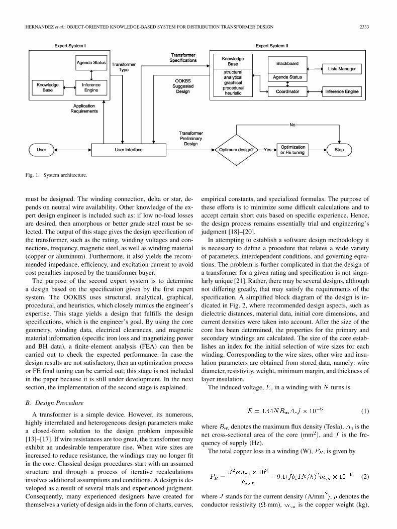
In attempting to establish a software design methodology itis necessary to define a procedure that relates a wide varietyof parameters, interdependent conditions, and governing equa-tions. The problem is further complicated in that the design ofa transformer for a given rating and specification is not singu-larly unique [21]. Rather, there may be several designs, althoughnot differing greatly, that may satisfy the requirements of thespecification. A simplified block diagram of the design is in-dicated in Fig. 2, where recommended design aspects, such asdielectric distances, material data, initial core dimensions, andcurrent densities were taken into account. After the size of thecore has been determined, the properties for the primary andsecondary windings are calculated. The size of the core estab-lishes an index for the initial selection of wire sizes for eachwinding. Corresponding to the wire sizes, other wire and insu-lation parameters are obtained from stored data, namely: wirediameter, resistivity, weight, minimum margin, and thickness oflayer insulation.
The induced voltage, , in a winding with turns is
(1)
where denotes the maximum flux density (Tesla), is thenet cross-sectional area of the core mm , and is the fre-quency of supply (Hz).
The total copper loss in a winding (W), , is given by
(2)
where stands for the current density A/mm , denotes theconductor resistivity ( mm), is the copper weight (kg),
2334 IEEE TRANSACTIONS ON MAGNETICS, VOL. 44, NO. 10, OCTOBER 2008
Fig. 2. Transformer design flowchart.
and is the density of cooper kg/m . denotes the radialconductor thickness (mm), is the winding ampere-turns, and
represents the winding height (mm).The percentage resistance , reactance , impedance
, and efficiency are computed with the followingequations:
(3)
(4)
(5)
(6)
where S stands for the rating transformer power (VA),mm denote mean turn diameters multiplied by the gap of be-
tween windings and thickness of primary and secondary wind-ings respectively. represents the total winding losses, PFdenotes the power factor and is the no-load loss ob-tained from the magnetizing curve and core flux density data.
The formulation of the design problem involves the objectiveand constraints functions in terms of design variables. The cur-rent densities of windings, core flux density, height of window,and core diameter have been chosen as independent variables.The choice of these variables is based on their significanteffect on the impedance, efficiency, and magnetizing current.The initial values of flux density, core diameter, and heightof core window were determined by recommended values of
transformer designers; these values are usually expressed as afunction of transformer rated apparent power and transformersmanufactures use them in their designs [18]–[21]. Initial valuesof winding current densities were recommended by a localmanufacturer and they are in the range of 1.5–3.5 A/mm . Allthese variables were later modified by the knowledge-basedsystem that mimics the designer expertise; the system is alsoaware of design constraints and of the specified transformerpower that is given by
(7)
where is the conductor area mm .
III. DESIGN AND IMPLEMENTATION
A. Object Representation
The physical composition of transformers and the methodsfor computing their properties are represented as a hierarchyof objects. Thus, a distribution transformer consists of com-ponents such as a core, a primary winding, and a secondarywinding. Associated with each type of component is a designprocedure, which is basically a set of instructions to each ofthe subcomponents to design itself. Each subcomponent hasa design method that is then executed to determine its prop-erties. Data and functionality of a distribution transformer areexpressed by classes as shown in Table I. Characteristic ele-ments of the transformer were chosen to construct the funda-mental classes shown in Table I. Consequently, the data shownin this table do not include all the classes of the application.Attributes listed are the most relevant. Classes were reused inthe simplest way, using an object of classes directly. Besides,objects of classes were placed inside new classes. In this way,the transformer class was made of the classes listed in Table I,combining them to achieve the functionality desired in this newclass, making use of what is known as composition (or moregenerally, aggregation).
B. Design Implementation
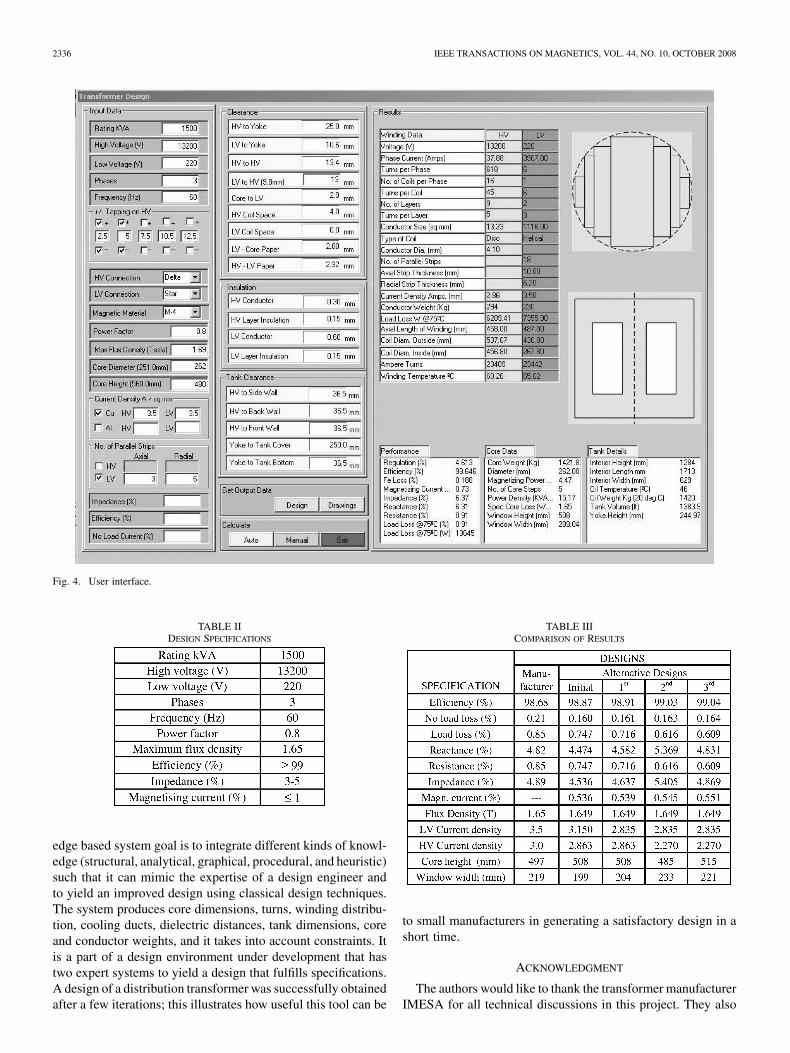
The system includes a user interface to control the executionof both stages. In the first stage, the user must provide the ap-plication requirements following a sequence of instructions in-dicated by the user interface, as shown in Fig. 3.
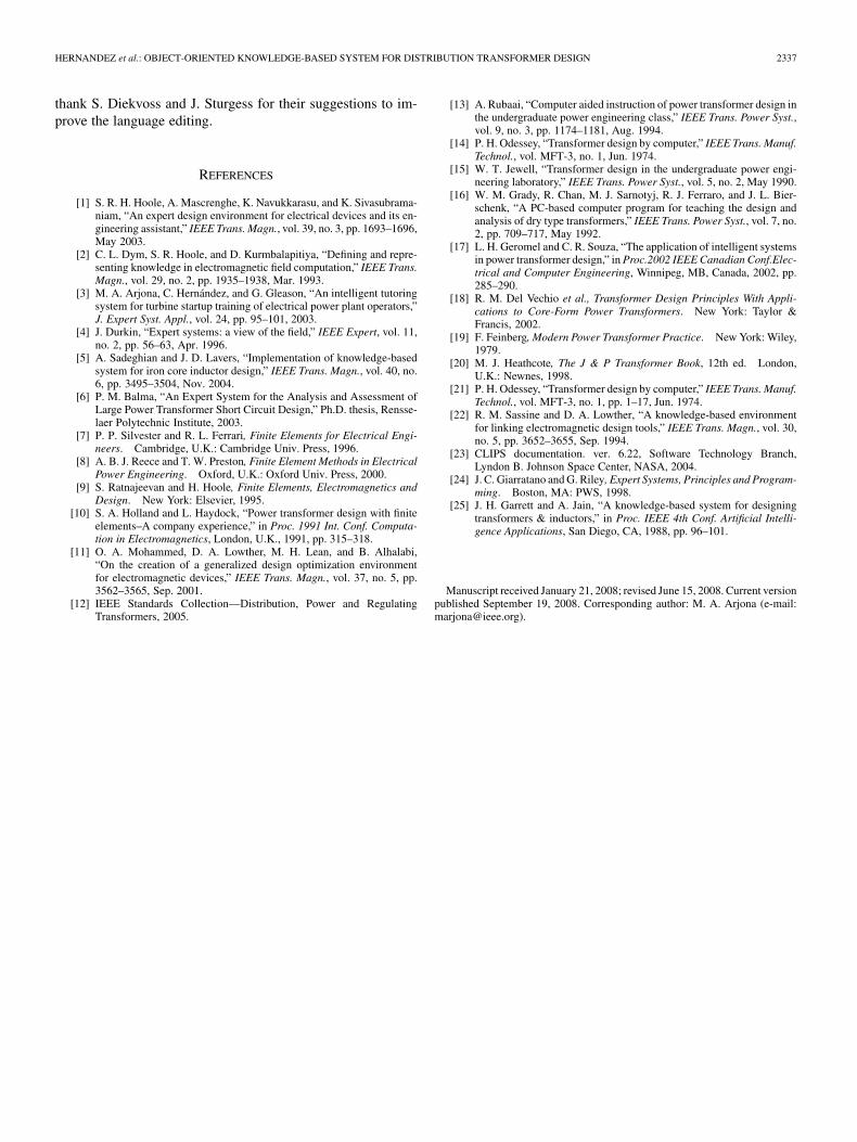
In the second stage, the user must provide the transformerspecifications via a user interface as shown in Fig. 4. A managerfor the lists of designs, a communication component referred toas a blackboard [3], [22] and a design coordinator are includedin the Expert System of the second stage.
Expert knowledge is represented by English-like sentencesknown as rules. An example of a used rule to improve efficiencyis: If efficiency is low then current density must be decreased.CLIPS (C-Language Integrated Production System) is used asthe expert system development and delivery vehicle [23], [24].
The second stage starts with the generation of an initial de-sign of the entire transformer by using a predetermined designmodel. Afterwards, the system generates and tests new design
HERNANDEZ et al.: OBJECT-ORIENTED KNOWLEDGE-BASED SYSTEM FOR DISTRIBUTION TRANSFORMER DESIGN 2335
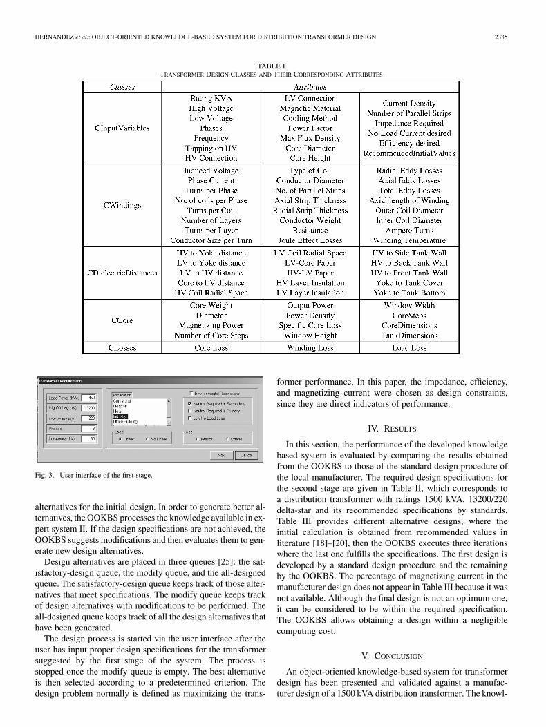
TABLE ITRANSFORMER DESIGN CLASSES AND THEIR CORRESPONDING ATTRIBUTES
Fig. 3. User interface of the first stage.
alternatives for the initial design. In order to generate better al-ternatives, the OOKBS processes the knowledge available in ex-pert system II. If the design specifications are not achieved, theOOKBS suggests modifications and then evaluates them to gen-erate new design alternatives.
Design alternatives are placed in three queues [25]: the sat-isfactory-design queue, the modify queue, and the all-designedqueue. The satisfactory-design queue keeps track of those alter-natives that meet specifications. The modify queue keeps trackof design alternatives with modifications to be performed. Theall-designed queue keeps track of all the design alternatives thathave been generated.
The design process is started via the user interface after theuser has input proper design specifications for the transformersuggested by the first stage of the system. The process isstopped once the modify queue is empty. The best alternativeis then selected according to a predetermined criterion. Thedesign problem normally is defined as maximizing the trans-
former performance. In this paper, the impedance, efficiency,and magnetizing current were chosen as design constraints,since they are direct indicators of performance.
IV. RESULTS
In this section, the performance of the developed knowledgebased system is evaluated by comparing the results obtainedfrom the OOKBS to those of the standard design procedure ofthe local manufacturer. The required design specifications forthe second stage are given in Table II, which corresponds toa distribution transformer with ratings 1500 kVA, 13200/220delta-star and its recommended specifications by standards.Table III provides different alternative designs, where theinitial calculation is obtained from recommended values inliterature [18]–[20], then the OOKBS executes three iterationswhere the last one fulfills the specifications. The first design isdeveloped by a standard design procedure and the remainingby the OOKBS. The percentage of magnetizing current in themanufacturer design does not appear in Table III because it wasnot available. Although the final design is not an optimum one,it can be considered to be within the required specification.The OOKBS allows obtaining a design within a negligiblecomputing cost.
V. CONCLUSION
An object-oriented knowledge-based system for transformerdesign has been presented and validated against a manufac-turer design of a 1500 kVA distribution transformer. The knowl-
2336 IEEE TRANSACTIONS ON MAGNETICS, VOL. 44, NO. 10, OCTOBER 2008
Fig. 4. User interface.
TABLE IIDESIGN SPECIFICATIONS
edge based system goal is to integrate different kinds of knowl-edge (structural, analytical, graphical, procedural, and heuristic)such that it can mimic the expertise of a design engineer andto yield an improved design using classical design techniques.The system produces core dimensions, turns, winding distribu-tion, cooling ducts, dielectric distances, tank dimensions, coreand conductor weights, and it takes into account constraints. Itis a part of a design environment under development that hastwo expert systems to yield a design that fulfills specifications.A design of a distribution transformer was successfully obtainedafter a few iterations; this illustrates how useful this tool can be
TABLE IIICOMPARISON OF RESULTS
to small manufacturers in generating a satisfactory design in ashort time.
ACKNOWLEDGMENT
The authors would like to thank the transformer manufacturerIMESA for all technical discussions in this project. They also
HERNANDEZ et al.: OBJECT-ORIENTED KNOWLEDGE-BASED SYSTEM FOR DISTRIBUTION TRANSFORMER DESIGN 2337
thank S. Diekvoss and J. Sturgess for their suggestions to im-prove the language editing.
REFERENCES
[1] S. R. H. Hoole, A. Mascrenghe, K. Navukkarasu, and K. Sivasubrama-niam, “An expert design environment for electrical devices and its en-gineering assistant,” IEEE Trans. Magn., vol. 39, no. 3, pp. 1693–1696,May 2003.
[2] C. L. Dym, S. R. Hoole, and D. Kurmbalapitiya, “Defining and repre-senting knowledge in electromagnetic field computation,” IEEE Trans.Magn., vol. 29, no. 2, pp. 1935–1938, Mar. 1993.
[3] M. A. Arjona, C. Hernández, and G. Gleason, “An intelligent tutoringsystem for turbine startup training of electrical power plant operators,”J. Expert Syst. Appl., vol. 24, pp. 95–101, 2003.
[4] J. Durkin, “Expert systems: a view of the field,” IEEE Expert, vol. 11,no. 2, pp. 56–63, Apr. 1996.
[5] A. Sadeghian and J. D. Lavers, “Implementation of knowledge-basedsystem for iron core inductor design,” IEEE Trans. Magn., vol. 40, no.6, pp. 3495–3504, Nov. 2004.
[6] P. M. Balma, “An Expert System for the Analysis and Assessment ofLarge Power Transformer Short Circuit Design,” Ph.D. thesis, Rensse-laer Polytechnic Institute, 2003.
[7] P. P. Silvester and R. L. Ferrari, Finite Elements for Electrical Engi-neers. Cambridge, U.K.: Cambridge Univ. Press, 1996.
[8] A. B. J. Reece and T. W. Preston, Finite Element Methods in ElectricalPower Engineering. Oxford, U.K.: Oxford Univ. Press, 2000.
[9] S. Ratnajeevan and H. Hoole, Finite Elements, Electromagnetics andDesign. New York: Elsevier, 1995.
[10] S. A. Holland and L. Haydock, “Power transformer design with finiteelements–A company experience,” in Proc. 1991 Int. Conf. Computa-tion in Electromagnetics, London, U.K., 1991, pp. 315–318.
[11] O. A. Mohammed, D. A. Lowther, M. H. Lean, and B. Alhalabi,“On the creation of a generalized design optimization environmentfor electromagnetic devices,” IEEE Trans. Magn., vol. 37, no. 5, pp.3562–3565, Sep. 2001.
[12] IEEE Standards Collection—Distribution, Power and RegulatingTransformers, 2005.
[13] A. Rubaai, “Computer aided instruction of power transformer design inthe undergraduate power engineering class,” IEEE Trans. Power Syst.,vol. 9, no. 3, pp. 1174–1181, Aug. 1994.
[14] P. H. Odessey, “Transformer design by computer,” IEEE Trans. Manuf.Technol., vol. MFT-3, no. 1, Jun. 1974.
[15] W. T. Jewell, “Transformer design in the undergraduate power engi-neering laboratory,” IEEE Trans. Power Syst., vol. 5, no. 2, May 1990.
[16] W. M. Grady, R. Chan, M. J. Sarnotyj, R. J. Ferraro, and J. L. Bier-schenk, “A PC-based computer program for teaching the design andanalysis of dry type transformers,” IEEE Trans. Power Syst., vol. 7, no.2, pp. 709–717, May 1992.
[17] L. H. Geromel and C. R. Souza, “The application of intelligent systemsin power transformer design,” in Proc.2002 IEEE Canadian Conf.Elec-trical and Computer Engineering, Winnipeg, MB, Canada, 2002, pp.285–290.
[18] R. M. Del Vechio et al., Transformer Design Principles With Appli-cations to Core-Form Power Transformers. New York: Taylor &Francis, 2002.
[19] F. Feinberg, Modern Power Transformer Practice. New York: Wiley,1979.
[20] M. J. Heathcote, The J & P Transformer Book, 12th ed. London,U.K.: Newnes, 1998.
[21] P. H. Odessey, “Transformer design by computer,” IEEE Trans. Manuf.Technol., vol. MFT-3, no. 1, pp. 1–17, Jun. 1974.
[22] R. M. Sassine and D. A. Lowther, “A knowledge-based environmentfor linking electromagnetic design tools,” IEEE Trans. Magn., vol. 30,no. 5, pp. 3652–3655, Sep. 1994.
[23] CLIPS documentation. ver. 6.22, Software Technology Branch,Lyndon B. Johnson Space Center, NASA, 2004.
[24] J. C. Giarratano and G. Riley, Expert Systems, Principles and Program-ming. Boston, MA: PWS, 1998.
[25] J. H. Garrett and A. Jain, “A knowledge-based system for designingtransformers & inductors,” in Proc. IEEE 4th Conf. Artificial Intelli-gence Applications, San Diego, CA, 1988, pp. 96–101.
Manuscript received January 21, 2008; revised June 15, 2008. Current versionpublished September 19, 2008. Corresponding author: M. A. Arjona (e-mail:[email protected]).