Embed Size (px)
Citation preview
(‘ompmr lnrqrmd Manufacturing Sy.\mm Vol. Y. No. I, pp 3S4X. IYYh Copyright 0 1996 Puhhshed by Elsevier Smnce I.td
Printed I” Great Rr~tam. All nghts reserved 13951--524WY6 $15.00 + 0 IKI
ELSEVIER 0951~5240(95)ooo364
Object-oriented resource models: their role in specifying components of integrated manufacturing systems
Marcos Wilson C Aguiar, I Shaun Murgatroyd and John M Edwards Manufacturing Systems Integration Research Institute, Loughborough University of Technology, Loughborough, Leicestershire LEll 3TU, UK (e-mail:J. M. [email protected])
In response to the need to identify improved operating strategies within manufacturing enterprises, a number of formal methods for enterprise engineering have been defined. Predominantly, these methodologies take a ‘top down’ approach based on an analysis of business requirements. Top down design must be tempered by an understanding that manufacturing processes are implemented using what are often inflexible hardware and software resources. This paper describes a CASE environment which provides structured support for resource modelling based on object orientation, and demonstrates the necessary integration with a top down enterprise engineering workbench based on the CIM-OSA reference architecture. The paper concludes by identifying requirements for future resource reference models that will be required to support enterprise engineering and that should be supplied by resource vendors. Copyright @ 1996 Published by Elsevier Science Ltd.
Keywords: manufacturing, object-orientation, CASE, resource, CIM-OSA
Introduction
Intense competition within global markets is driving manufacturing enterprises to increase their levels of efficiency. The early 1990s has seen the emergence of a number of reference architectures, which propose a conceptual framework, and associated methodology, which support the top down re-engineering of manu- facturing systems. Most notable amongst these refer- ence architectures are CJM-OSA’, PERA2, GRA13 and ARIS4. The consensus view shared by these architectures is that manufacturing enterprise engineer- ing should be approached from a top down perspective, driven by high level goals based on an analysis of the business needs of the enterprise. In practice, it is often difficult to map top down designs onto real manufactur- ing resources, based on machines and application software which are often inflexible, particularly as these methodologies are invariably applied to re-engineering existing systems.
This paper supports the need for modelling manu- facturing resources, and for enabling their structured incorporation in the top down creation of integrated manufacturing systems. Details of the degree to which resource models influence the top down modelling process during its lifecycle phases are presented, where this influence begins as early as requirements definition. The paper describes CASE workbenches created by researches at the MS1 Research Institute. The SEW-
OSA workbench is based on the CIM-OSA reference architecture, with extensions to define automated support for system implementation. It provides a top down methodology which separately models manufacturing system requirements definition, design specification, and implementation description using consistent models such that implementation is in line with requirements. A detailed treatment of the SEW- OSA workbench is given in Aguiar’. Structured support for resource modelling is provided through the use of complementary object oriented CASE tools based on both the BOOCH6 methodology for software engin- eering and the EXPRESS information modelling language7. The 00 tools derive their manufacturing perspective through reference object classes of manu- facturing entities. In this way, they are particularly useful for describing manufacturing resources. A detailed treatment of the 00 tools is given in Aguiar et al.’
‘Model driven CIM’ toolset
The two CASE workbenches introduced above form part of a prototype set of complementary manufacturing enterprise engineering tools collectively known as the ‘Model driven CIM’ toolset. This suite of CASE workbenches has been created over the past three years at the MS1 Research Institute, as part of a UK
33
34
government supported research project. The toolset provides support for the enterprise engineering life- cycle phases of conceptual design, requirements defini- tion, detailed design, implementation, runtime and maintenance.
During the course of the work, it has been established that manufacturing systems design must be underpinned by a capability to ‘exercise’ design models, in order to trial different scenarios and identify the most appropri- ate solution. This ‘model enactment’ has been achieved through facilities for both model simulation and rapid prototyping. During rapid prototyping, models created during the detailed design phase are combined with infrastructural software support elements to create a working system driving emulated manufacturing resources. The move from a rapid prototype to a final system implementation requires the incremental replacement of emulated resources with real manu- facturing functional entities. This incremental cycle of design, simulation, redesign, rapid prototyping, redesign, etc. can potentially lead to much improved final system implementations.
The methodology described above, based on the enactment of design models, is worth nothing if the simulated and emulated resources employed cannot eventually be replaced by real manufacturing resources. There is then a need to work ‘bottom up’, modelling available resources (either existing or on the market), such that these models can be combined with top down descriptions to create meaningful executable systems. Within the context of CASE environments, there is also a need to systemize and automate this integration between bottom up resources and top down process descriptions such that the design process is appropriately influenced at each lifecycle phase.
This influence begins at requirements definition as an awareness of resource constraints through knowledge of abstract classes of resource capability, and dominates considerations when progressing from design speci- fication to the description of the physical system implementation.
Reference and resource modelling .
The need for reference models of particular manu- facturing domains is well recognized. These models are essentially frameworks to support system analysis, design and construction together with class libraries of the applicable resources and processes described in terms of their interfaces, characteristics and capabilities. Research worldwide is striving to develop these models, some of the main initiatives are:
Kimura’ who developed an early manufacturing model which attempted to represent the whole of the factory in terms of its resources and processes, e.g. buildings, materials, people, machines, fixtures, etc.; the international standardization work of ISO/ TC184/SC4/WG810, which is developing a resource
Object-oriented resource models: M W C Aguiar et al.
usage management model aimed at optimizing the use of both manufacturing resource and process; the ESPRIT/VOICE” project, which has developed a number of reference models for particular manu- facturing domains via the application of the CIM- OSA framework’ ; the SEMATECH consortiumi2, which is developing a CIM reference framework for semiconductor manu- facturing operations; the MOSES project13 which has developed a manufacturing model describing the manufacturing capability of an enterprise within the context of an information sharing platform to aid concurrent engineering. This model is based on early manufac- turing modelling work carried out within the IMPPACT project14, which defined both factory and process models and on the work carried out by Al- Ashaab and Young15; the ESPRIT/AIT project16, which is developing both an IT reference model and a process reference model based primarily around the automotive and aerospace industries.
These initiatives provide valuable input to the crea- tion of generic reference models. The work described in this paper complements this work through providing an integrated CASE environment encapsulating a methodology for resource modelling and the use of reference resource models in support of top down manufacturing enterprise engineering.
Context of the resource modelling tools
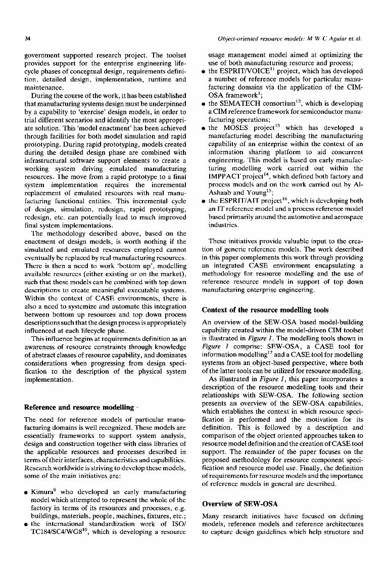
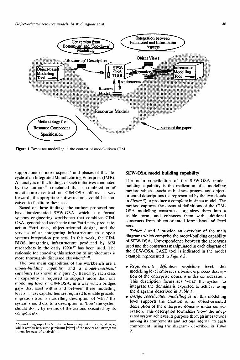
An overview of the SEW-OSA based model-building capability created within the model-driven CIM toolset is illustrated in Figure 2. The modelling tools shown in Figure 2 comprise: SEW-OSA, a CASE tool for information modelling” and a CASE tool for modelling systems from an object-based perspective, where both of the latter tools can be utilized for resource modelling.
As illustrated in Figure 2, this paper incorporates a description of the resource. modelling tools and their relationships with SEW-OSA. The following section presents an overview of the SEW-OSA capabilities, which establishes the context in which resource speci- fication is performed and the motivation for its definition. This is followed by a description and comparison of the object oriented approaches taken to resource model definition and the creation of CASE tool support. The remainder of the paper focuses on the proposed methodology for resource component speci- fication and resource model use. Finally, the definition of requirements for resource models and the importance of reference models in general are described.
Overview of SEW-OSA
Many research initiatives have focused on defining models, reference models and reference architectures to capture design guidelines which help structure and
Object-oriented resource models: M W C Aguiar et al 35
Figure 1 Resource modelling in the context of model-driven CIM
support one or more aspects* and phases of the life- cycle of an Integrated Manufacturing Enterprise (IME).
An analysis of the findings of such initiatives conducted by the authors” concluded that a combination of architectures centred on CIM-OSA offered a way forward, if appropriate software tools could be con- ceived to facilitate their use.
Based on these findings, the authors proposed and have implemented SEW-OSA, which is a formal systems engineering workbench that combines CIM- OSA, generalized stochastic time Petri nets, predicate- action Petri nets, object-oriented design, and the
services of an integrating infrastructure to support systems integration projects. In this work, the CIM-
BIOS integrating infrastructure produced by MS1
researchers in the early 1990~‘~ has been used. The rationale for choosing this selection of architectures is more thoroughly discussed elsewhere5,20.
The two main capabilities of the workbench are a model-building capability and a model-enactment capability (as shown in Figure 2). Basically, each class
of capability is required to support more than one modelling level of CIM-OSA, in a way which bridges gaps that exist within and between these modelling
levels. These capabilities are required to enable graceful migration from a modelling description of ‘what’ the system should do, to a description of ‘how’ the system should do it, by means of the actions executed by its components.
*A modelling aspect is ‘an abstraction viewpoint of one total view, which emphasizes Some particular [view] of the model and disregards others for ease of analysis’*‘.
SEW-OSA model building capability
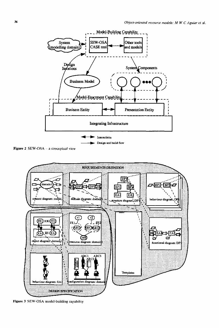
The main contribution of the SEW-OSA model-
building capability is the realization of a modelling method which associates business process and object- oriented descriptions (as represented by the two clouds
in Figure 3) to produce a complete business model. The method captures the essential definitions of the CIM- OSA modelling constructs, organizes them into a usable form, and enhances them with additional constructs from object-oriented formalisms and Petri nets.
Tables 1 and 2 provide an overview of the main
diagrams which comprise the model-building capability of SEW-OSA. Correspondence between the acronyms used and the constructs manipulated in each diagram of
the SEW-OSA CASE tool is indicated in the model example represented in Figure 3:
Requirements definition modelling level: this modelling level embraces a business process descrip- tion of the enterprise domains under consideration. This description formalizes ‘what’ the system to integrate the domains is expected to achieve using the diagrams described in Table 1. Design specification modelling level: this modelling level supports the creation of an object-oriented
description of the enterprise domains under consid- eration. This description formalizes ‘how’ the integ- rated system achieves its purpose through interactions among its components and actions internal to each component, using the diagrams described in Table 2.
36 Object-oriented resource models: M W C Aguiar et al.
Model-Building Qtabilit]L I----------- --- ---I
It&grating Infrastructure
M Inte.rsctions
-+ Design and build flow
Figure 2 SEW-OSA - a conceptual view
Figure 3 SEW-OSA model-building capability
Object-oriented resource models: M W C Aguiar et al. 31
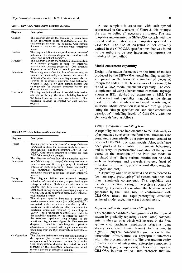
Table 1 SEW-OSA requirements definition diagrams A text template is associated with each symbol represented in the diagrams of Figure 3, this prompts the user to define all necessary attributes. The text templates implemented in SEW-OSA comply with the format and attributes of the templates specified by CIM-OSA. The use of diagrams is not explicitly defined in the CIM-OSA specifications, but was found by the authors to be very important to improve the usability of the method.
Diagram Description
Context
Domain
structure
Behaviour
Functional
This diagram defines the domains (i.e. main areas of an enterprise) under consideration, and the relationships between the domains. One context diagram is created for each individual enterprise model. This diagram defines the major domain processes of a domain. One domain diagram is creaied for each CIM-OSA-compliant domain*‘. This diagram defines the functional decomposition of a domain processes in terms of enterprise activities and business processes*‘. One structure diagram is created for each domain process. These diagrams define the flow of control used to execute the functionality of a domain process and its business processes. Behaviour diagrams can also be referred to as process diagrams. One behaviour diagram is created for each domain process and subsequently for business processes within the domain process structure. This diagram defines flows of material, information and control through the atomic building blocks of the domain process (i.e. enterprise activities*‘. One functional diagram is created for each domain process.
Table 2 SEW-OSA design specification diagrams
Object
Activity Behaviour
Entity Behaviour
Resource
Configuration
This diagram defines the flow of messages between functional entities, the business entity (i.e. enter- prise activities) and the information entity of CIM- OSA*‘. One object diagram is created- for each CIM-OSA-compliant domain. This diagram defines how the enterprise activity uses (via message exchanges) the integrated opera- tion environment (i.e. a grouping of functional entities, or FEs), to perform its basic functionality (i.e. functional operations*‘). One activity behaviour diagram is created for each enterprise activity. This diagram defines the expected external behaviour of a functional entity as perceived by the enterprise activities. Such a description is used to emulate the behaviour of an active resource component during the rapid-prototyping stage of a system. One entity behaviour diagram is created for each functional entity. This diagram specifies instances of active and passive resource components (i.e. ARC and PRC”) associated with the classes specified by their functional entities which are able to execute the functional operations required by an enterprise activity. These functional operations are related to the capability required by the enterprise activity; the resource capability being defined in the functional diagram (see Figure 3). One resource diagram is created for each integrated operation environment associated with a particular domain (stemming from the IOE construct, as illustrated in Figure 3). This diagram defines the computer configuration of the system (i.e. where each active resource component will be executed or interfaced with). One configuration diagram is created for each segment of the integrating infrastructure which serves a particular enterprise domain.
Model enactment capability
Design information formalized in the form of models produced by the SEW-OSA model-building capability are passed in the form of a number of pieces of interpreted code (i.e. the business model in Figure 2) to the SEW-OSA model enactment capability. The code is implemented using a behavioural transition language known as BTL, devised by researchers at MST. The model-enactment capability manipulates the design model to enable simulation and rapid prototyping of solutions. Model execution is achieved through popu- lating the ‘design specification’ and ‘implementation description’ modelling levels of CIM-OSA with the elements defined as follows.
Design specification modelling level
A capability has been implemented to facilitate analysis of generalized-stochastic time Petri nets. These nets are generated automatically by a software tool created to process CIM-OSA functional models. Also, tools have been produced to stimulate the dynamic behaviour, and to carry out performance evaluation of the system based on the execution of the Petri net model in simulated time22 (h ere various metrics can be used, such as lead-time and cycle-time values, level of utilization of resources, profile of work-flow, work-in- progress and cost).
A capability was also conceived and implemented to facilitate rapid prototyping2’ of system solutions and their (emulated) components. This capability was included to facilitate testing of the system structure by providing a means of executing the business model generated by the CASE tool. In conformance with CIM-OSA ideas, the rapid-prototyping capability achieved model execution via a business entity.
Implementation description modelling level
This capability facilitates configuration of the physical system by gradually replacing its (emulated) compon- ents by physical ones which will be used in the final system (i.e. machines, application programs, data storing devices and human beings). As illustrated in Figure 2, physical components gain access to the integrating infrastructure via appropriate interfaces within the presentation entity. The presentation entity provides means of integrating enterprise components (including legacy components). This entity maps the CIM-OSA internal protocol into protocols that are
38 ObjeCt-oriented resource models: M W C Aguiar et al.
understood by enterprise components (e.g. proprietary machine commands).
As introduced earlier, before a physical system is finally commissioned, there will typically be a series of iterations between the use of the model-building and the model-enactment capabilities. One of the most important contributions of SEW-OSA is that it facilitates these iterative processes in a structured and consistent manner bringing together conventionally separate life- cycle phases, from ‘requirements definition’ to the ‘configuration and execution’ of computer integrated manufacturing systems upon an industrially tested integrating infrastructure (i.e. CIM-BIOSYS). Poten- tially, this can lead to much improved solutions and much shorter design-to-build lead-times via what essentially becomes an integrated systems engineering process.
Resource specification in the context of SEW-OSA
Resource specification in the context of these two capabilities embraces mappings between different life- cycle processes to enable the specification of a physical solution based on an identified set of requirements.
This mapping includes enabling a ‘test’ of the properties and the quality of models which describe a relationship between a ‘problem’ and a ‘solution’ (i.e. the relationship between system requirements and a possible system configuration). To support this mapping, it is envisaged that use should be made of a library of reference models (i.e. models of system configurations and their resource components) that could encapsulate knowledge of (a) user requirements in the form of CIM-OSA-based models, and (b) alternative system components modelled in an object-oriented language, thereby integrating two complementary descriptions of the system: a business process view and an object- oriented view (as illustrated by the two clouds in Figure
3).
Object oriented view of manufacturing systems
Contemporary manufacturing systems can be consid- ered as being a collection of objects (machines, people, data, etc.) supported by, or implemented as, a complex set of software systems communicating in a structured or semi-structured manner to achieve a manufacturing goal. As such, object oriented methods can aid in their design, analysis and implementation.
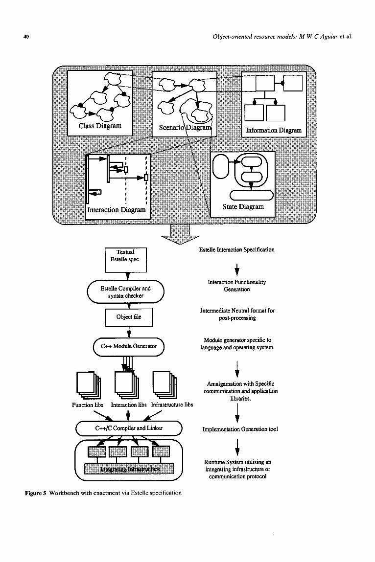
The object-oriented workbench created by MS1 researchers (Figure 5) supports system decomposition via the use of a series of object or scenario diagrams. These diagrams depict, at system level, the physical and logical objects which comprise the system, as well as their logical and physical connections in terms of message passing. The scenario diagrams capture the static nature of the system (in terms of object hierarchies and connections), and partially capture the dynamic behaviour of the system through message numbering and type. The behaviour of the system is further
captured in a series of Hare1 state charts. These state diagrams may range from representing the states of the whole system, through sub-systems, to representing the state transitions of individual objects. Enactment of the models captured using the workbench is achieved through an Estelle specification8T23 (see Figure 5). In addition to capturing system functionality, the work- bench allows for the construction and incorporation of resource models from which the specific system objects (instances) may be selected. The following sections describe the two approaches implemented by MS1 researchers, the first based on Booth’s class diagrams and the second based around the EXPRESS informa- tion modelling language.
Object oriented resource modelling
A manufacturing resource model is essentially a set of manufacturing object abstractions (classes) comprising encapsulated state and behaviour with attendant visible services. These classes represent the minimum infor- mation required to build applications. Particular classes within these models may range in their scope of applicability from a specific manufacturing domain (e.g. electronics assembly) through any manufacturing domain (e.g. discrete batch manufacture) to any enterprise (e.g. financial institutions). Much of the current research activity in the areas of resource modelling and reference model generation is aimed at defining their useful levels of granularity and scope, together with methodologies for model aggregation or federation24.
The SEW-OSA model enactment capability (in line with research elsewhere) places much emphasis on being able to use models of manufacturing scenarios to generate much of the underlying manufacturing system software required for runtime execution and manage- ment of the manufacturing system. The degree to which resource models can contribute to this code generation process depends very much upon the model’s scope and granularity. At one level, the resource model allows the system designer to make better informed decisions when associating a particular system resource to a particular function or group of functions by allowing optimum matching of resource capabilities to their analysed requirements. In this case, the resource model seeks to influence the system designer through access to information on resource capabilities, where attributes are generally textural (descriptive/subjective) in nature, and require a knowledgeable system designer to interpret them. At another level, dependent on the scope of the resource model, interface specifications, application programs and behavioural representations can be incorporated into the system code from the resource models. Strictly, this does not constitute code generation in its purest form, since there are no intuitive steps involved, simply an importing of code fragments. However, if the method used to model the resources is chosen suitably, it is possible to generate much of the code required to build the schema that
Object-oriented resource models: M W C Aguiar et al.
n
39
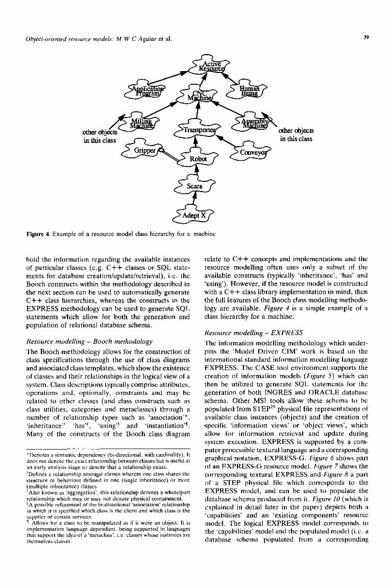
other objects in this class
Figure 4 Example of a resource model class hierarchy for a machine
hold the information regarding the available instances of particular classes (e.g. C++ classes or SQL state- ments for database creation/update/retrieval), i.e. the Booth constructs within the methodology described in the next section can be used to automatically generate C++ class hierarchies, whereas the constructs in the EXPRESS methodology can be used to generate SQL statements which allow for both the generation and population of relational database schema.
Resource modelling - Booth methodology
The Booth methodology allows for the construction of class specifications through the use of class diagrams and associated class templates, which show the existence of classes and their relationships in the logical view of a system. Class descriptions typically comprise attributes, operations and, optionally, constraints and may be related to other classes (and class constructs such as class utilities, categories and metaclasses) through a number of relationship types such as ‘association’*, ‘inheritance’+ ‘has”, ‘using’” and ‘instantiation’n. Many of the constructs of the Booth class diagram
*Denotes a semantic dependency (bi-directional, with cardinality). It does not denote the exact relationship between classes but is useful at an early analysis stage to denote that a relationship exists.
‘Defines a relationship amongst classes wherein one class shares the structure or behaviour defined in one (single inheritance) or more (multiple inheritance) classes. $Also known as ‘aggregation’, this relationship denotes a whole/part relationship which may or may not denote physical containment. $A possible refinement of the bi-directional ‘association’ relationship in which it is specified which class is the client and which class is the supplier of certain services. 7 Allows for a class to be manipulated as if it were an object. It is implementation language dependant, being supported in languages that support the idea of a ‘metaclass’, i.e. classes whose instances are themselves classes.
relate to C++ concepts and implementations and the resource modelling often uses only a subset of the available constructs (typically ‘inheritance’, ‘has’ and ‘using’). However, if the resource model is constructed with a C++ class library implementation in mind, then the full features of the Booth class modelling methodo- logy are available. Figure 4 is a simple example of a class hierarchy for a machine.
Resource modelling - EXPRESS
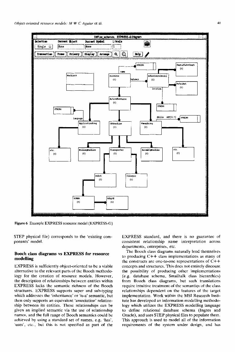
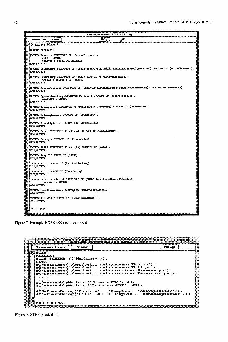
The information modelling methodology which under- pins the ‘Model Driven CIM’ work is based on the international standard information modelling language EXPRESS. The CASE tool environment supports the creation of information models (Figure 5) which can then be utilized to generate SQL statements for the generation of both INGRES and ORACLE database schema. Other MS1 tools allow these schema to be populated from STEP25 physical file representations of available class instances (objects) and the creation of specific ‘information views’ or ‘object views’, which allow for information retrieval and update during system execution. EXPRESS is supported by a com- puter processible textural language and a corresponding graphical notation, EXPRESS-G. Figure 6 shows part of an EXPRESS-G resource model. Figure 7 shows the corresponding textural EXPRESS and Figure 8 a part of a STEP physical file which corresponds to the EXPRESS model, and can be used to populate the database schema produced from it. Figure 10 (which is explained in detail later in the paper) depicts both a ‘capabilities’ and an ‘existing components’ resource model. The logical EXPRESS model corresponds to the ‘capabilities’ model and the populated model (i.e. a database schema populated from a corresponding
40 Object-oriented resource models: M W C Aguiar et al.
Function libs Interaction libs Infrastructure libs
Estelle Interaction Specification
t
Intexaction Functionality Generation
Intermediate Neutral format for post-processing
Module generator specific to language and operating system.
Amalgamation with Specific communication and application
libraries.
Implementation Generation tool
Runtime System utilising an integrating infrastructure or
communication protocol
Figul re 5 Workbench with enactment via Estelle specification
Object-oriented resource models: M W C Aguiar et al.
Figure 6 Example EXPRESS resource model (EXPRESS-G)
STEP physical file) corresponds to the ‘existing com- ponents’ model.
Booth class diagrams vs EXPRESS for resource modelling
EXPRESS is sufficiently object-oriented to be a viable alternative to the relevant parts of the Booth methodo- logy for the creation of resource models. However, the description of relationships between entities within EXPRESS lacks the semantic richness of the Booth structures. EXPRESS supports super and sub-typing which addresses the ‘inheritance’ or ‘is-a’ semantic, but then only supports an equivalent ‘association’ relation- ship between its entities. These relationships can be given an implied semantic via the use of relationship names, and the full range of Booth semantics could be achieved by usi.ng a standard set of names, e.g. ‘has’, ‘uses’, etc., but this is not specified as part of the
EXPRESS standard, and there is no guarantee of consistent relationship name interpretation across departments, enterprises, etc.
The Booth class diagrams naturally lend themselves to producing C++ class implementations as many of the constructs are one-to-one representations of C++ concepts and structures. This does not entirely discount the possibility of producing other implementations (e.g. database schema, Smalltalk class hierarchies) from Booth class diagrams, but such translations require intuitive treatment of the semantics of the class relationships dependent on the features of the target implementation. Work within the MS1 Research Insti- tute has developed an information modelling methodo- logy which utilizes the EXPRESS modelhng language to define relational database schema (Ingres and Oracle), and uses STEP physical files to populate them. This approach is used to model all of the information requirements of the system under design, and has
42 Object-oriented resource models: M W C Aguiar et al.
f behave+ : BehaviouxaUodsl;
mtgmITY;
E - %~~~lfaohino SUPERTYPE OF (ONEOF(Trantporter, 1Iillin~achine,hsscnbl~achins)) SUBTYPE OF (ActiveResourcs);
RuaarBeinq SUPERTYPE OF (etc.) SWTYFE OF (ActiveResource); skills : SET[O:?] OF SIBINO;
shasoarce SUPEFiTWE OF (ONEOF(App?.icationProq, CNCllachine.RunzmEeinq)) SUB!tYPE OF (Rerource);
cationPro SUPERTYPE OF (etc.) STE OF (ActiveResource); anquaqe : STFiIRO;
porter SVPEFiTYFE OF (OREOF(Robot,Conveyor)) SW!WPE OF (CNCXachine) i
nghchine SUBTWE OF (CNCCgachim);
ENlTT!f hsse&lyllachins SUB!lYPE (CNCNachine);
E ENTITY Robot SUPERTYPE OF (SCARA) SUBTYPE OF (Tnnsporter); END_EWMlV;
OF (Transporter);
:EWITY SCARA SUPEF3YP.U OF (AdeptX) SUBTYPE OF (Robot); :LND_EHTITY;
t ;EWIT!TAdepu( SUBTYPE OF (SCAFJA); iEND_EMXTY;
IWTITY Behaviourallrodel SUPER!WPE OF (ONEOF
END_EWI!W;
EITFITY PetriNet SUBTYPE OF (BehatiouralJIodal);
Figure 7 ’ Example EXPRESS resource model
FILE SCHEMZk (C'Machinss')); HEADER;
DATA7
kib%ssomblyMachine <’ SicmcnsARC *, #3) ; #ll-A33cmtrlyMachine<'P~asonicXYZ', #d);
. . . . .
. . . . .
k2bZumsnRcing~'Bob', #l. <'CampLit'. 'AsayOpcrator')); #21-I-WmanEcing["B-ill'. #2. {'CompLit', 'ManualOperator'));
Figure 8 STEP physical file
Object-oriented resource models: M W C Aguiar et al. 43
source bebaviour object
Figure 9 Interface with a resource model
Figure 10 Use of a resource model
44 Object-oriented resource models: M W C Aguiar et al.
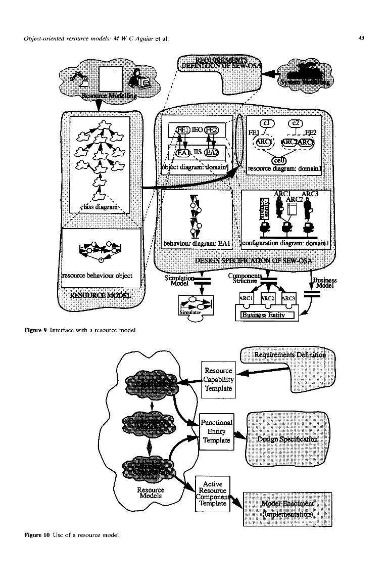
associated with it a mature set of tools for model manipulation and implementation. This approach was chosen by MS1 researchers for producing resource models in order to give a level of consistency in information system implementation and manipulation, but it must be stressed that the Booth approach may be used wherever it is considered to be appropriate for reasons of implementation, semantic content or famili- arity of use. The important point is that both approaches may be used for the resource modelling aspects of the SEW-OSA methodology and suitably integrated as depicted in Figure 9. Figure 9 shows how the resource tool is related to SEW-OSA. Through this link, the information encapsulated by the resource model can be used as an integral part of the SEW-OSA modelling method.
Methodology for resource model use
The overall process of using a resource model in the context of the design process encapsulated in SEW- OSA is illustrated in Figure IO. This figure relates the modelling stages associated with the use of the model- building and model-enactment capabilities of SEW- OSA with a resource model via templates of key modelling constructs.
The resource selection process starts with the defini- tion of the resource capability construct used in the functional diagram. An example of a resource capability template is shown in Figure 22, which is associated with the constructs identified as ‘RC’ in the functional diagram (see Figure 3). The resource capability con- struct must capture characteristic properties of a resource, described from the viewpoint of the user. This template provides an abstract definition of the overall requirements of a resource without defining details of physical resource components used to realize such a capability.
During progression to the design specification stage
TYPE: Manufacturing
ID- w-2
NAME: Placement capability
DESIGN AUTHOR~TYZ MarcoSAg&
DEXRIPTIO~ capability to populate boards
cAPABILIIYJ,wmIB~:
Activity: ACthe
Type of Activity: mechanical and repetitive
Figure 11 Example of a resource capability template
___,_____._-- .____
TYPE:
IDENTIFIm
NAME:
DESIGN AUTHOW
DEXR~PTIONZ
AmUTE
Functional Operations:
Behaviwr diagram:
TypedResource:
..----.
Manufscturing
PE-2
Placement Entity
MarcosAguisu
Functionality to populate boards
make(pcB) made(pcB)
~2_Behaviour_diagram
Machine
Figure 12 Example of a functional entity template
in Figure 3, resource components are expected to be defined with respect to representations of their func- tional (i.e. functional entity) and physical (i.e. active resource components) properties. A functional entity construct can be used to represent the class of inter- actions that a resource should support (this being related to the types of functional operations that the resource can provide). Figure 12 shows a typical functional entity template which was conceived by the authors to summarize its attributes of interest. Here, it should be noticed that its attributes define the type of functional operations supported, a more specific defini- tion of its type (e.g. a machine) and the internal behaviour that it is expected to demonstrate (e.g. a link to an entity behaviour diagram identified as FE-ZBehaviour_diagram).
The model of an active resource component needs to include a description of the information required by the integrating infrastructure to interact with the resource. To support both rapid prototyping and physical system execution, it was realized that an active resource component needed to be represented in an emulated form and in its final physical form. An example of such a description conceived for this purpose is presented in Figure 23. It should be noted that the attributes associated with the ‘integration features’ of such a resource define a link to a device driver which can be used by the CIM-BIOSYS integrating infrastructure to enable communication with a particular machine (e.g. SMT-dvc), any object-views (e.g. OV) required for the integration to occur (e.g. in this case, ‘Siemensinteg’ identifies information elements that need to be used to accomplish the integration), the name of the CIM- BIOSYS process which manages the integration (e.g. SIEMENS), the host computer to which the machine is attached (e.g. derek), the type of hardware interface
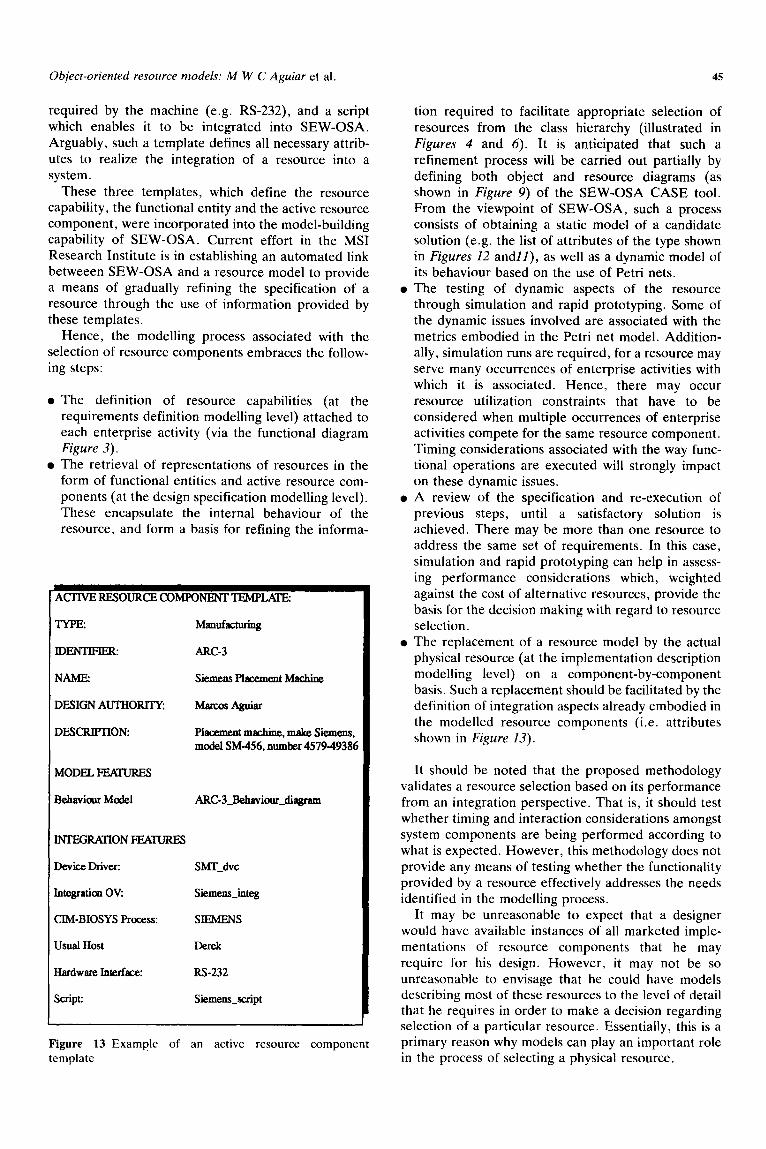
Object-oriented resource models: M W C Aguiar et al.
required by the machine (e.g. RS-232), and a script which enables it to be integrated into SEW-OSA. Arguably, such a template defines all necessary attrib- utes to realize the integration of a resource into a system.
These three templates, which define the resource capability, the functional entity and the active resource component, were incorporated into the model-building capability of SEW-OSA. Current effort in the MS1 Research Institute is in establishing an automated link betweeen SEW-OSA and a resource model to provide a means of gradually refining the specification of a resource through the use of information provided by these templates.
Hence, the modelling process associated with the selection of resource components embraces the follow- ing steps:
The definition of resource capabilities (at the requirements definition modelling level) attached to each enterprise activity (via the functional diagram Figure 3).
The retrieval of representations of resources in the form of functional entities and active resource com- ponents (at the design specification modelling level). These encapsulate the internal behaviour of the resource, and form a basis for refining the informa-
ACl-IVERESOURCECOMPONENTTEMPL~
TYPE: ManufactlJIillg
WENTFIFR ARC-3
NAME: Siemens Placement Machine
DESIGN AUTHORlTYz MarcQsA@liar
DESCRIPTION: Placement machine, make Siemens. model SM-456. number 457949386
MODEL PEXVRES
Bebviau Model ARC-3_Behaviouf_diagram
KTI’EGRATION m
Device Driver: SMT_dvc
Integration OV Siemens_integ
CIM-BIOSYS Process: SIEMJZNS
Usual Host
Hardware Interface: RS-232
script: Siemens_suipt
Figure 13 Example of an active resource component template
45
tion required to facilitate appropriate selection of resources from the class hierarchy (illustrated in Figures 4 and 6). It is anticipated that such a refinement process will be carried out partially by defining both object and resource diagrams (as shown in Figure 9) of the SEW-OSA CASE tool. From the viewpoint of SEW-OSA, such a process consists of obtaining a static model of a candidate solution (e.g. the list of attributes of the type shown in Figures 12 andll), as well as a dynamic model of its behaviour based on the use of Petri nets. The testing of dynamic aspects of the resource through simulation and rapid prototyping. Some of the dynamic issues involved are associated with the metrics embodied in the Petri net model. Addition- ally, simulation runs are required, for a resource may serve many occurrences of enterprise activities with which it is associated. Hence, there may occur resource utilization constraints that have to be considered when multiple occurrences of enterprise activities compete for the same resource component. Timing considerations associated with the way func- tional operations are executed will strongly impact on these dynamic issues. A review of the specification and re-execution of previous steps, until a satisfactory solution is achieved. There may be more than one resource to address the same set of requirements. In this case, simulation and rapid prototyping can help in assess- ing performance considerations which, weighted against the cost of alternative resources, provide the basis for the decision making with regard to resource selection. The replacement of a resource model by the actual physical resource (at the implementation description modelling level) on a component-by-component basis. Such a replacement should be facilitated by the definition of integration aspects already embodied in the modelled resource components (i.e. attributes shown in Figure 23).
It should be noted that the proposed methodology validates a resource selection based on its performance from an integration perspective. That is, it should test whether timing and interaction considerations amongst system components are being performed according to what is expected. However, this methodology does not provide any means of testing whether the functionality provided by a resource effectively addresses the needs identified in the modelling process.
It may be unreasonable to expect that a designer would have available instances of all marketed imple- mentations of resource components that he may require for his design. However, it may not be so unreasonable to envisage that he could have models describing most of these resources to the level of detail that he requires in order to make a decision regarding selection of a particular resource. Essentially, this is a primary reason why models can play an important role in the process of selecting a physical resource.
46
Resource model structure
The level of support described in the above methodo- logy should be encapsulated in the resource model (i.e. within a reference model of resource components). Structuring and populating such reference models is beyond the scope of this research. However, this research has identified necessary constituents of these models, namely:
A: a library of resource models structured according to various resource modelling views, namely:
a Resource Capability View (encapsulated by the Resource Capability construct) is required during the requirements definition phase. This provides an abstract description providing characteristic proper- ties of the resource; a Resource Behaviour View (encapsulated by the Functional Entity construct) is required during the design specification phase. This provides details of the resource external behaviour (i.e. the functional operations that the resource can provide); a Resource Emulation View (jointly encapsulated by Functional Entity and Active Resource Com- ponent constructs) is required during rapid proto- typing to define emulated resource interaction details; a Resource Implementation View (encapsulated by the Active Resource Component construct) is
Object-oriented resource models: M W C Aguiar et al.
required during the move to final system imple- mentation. This model provides detail of the interaction requirements of the real physical resource.
B: A means of creating relationships between these model views so that the experience acquired in previous designs, with regard to the process of refining a resource specification, can be formally captured in models (i.e. relationships between requirements definition and design specification). These relationships are referred to as ‘connectance models’* (see Figure 20).
Hence, the resource specification process consists of establishing relationships between attributes associated with a resource capability and associated functional entities and active resource components. In this manner, alternative specifications of resources retrieved from the resource model library can be automatically imported by the SEW-OSA CASE tool. The relationships represented in the connectance models are likely to possess many-to-many cardinality
*According to Kwikkers’“, connectance models describe connections in a particular field of knowledge. Connectance models consist of generalizations of point solutions encountered in particular designs. Kwikkers uses connectance models to retrieve a particular model from a library of reference models. Work on the definition of connectance models is being carried out at Karlsruhe University*‘, with which the MS1 institute has collaborative research links.
World of ModeIIing Technology
World of Integrating Infrastmctures
Figure 14 A key role for reference models
Object-oriented models: M W C Aguiar et al.
(i.e. there may be many active resource components
capable of providing a certain resource capability, and vice versa).
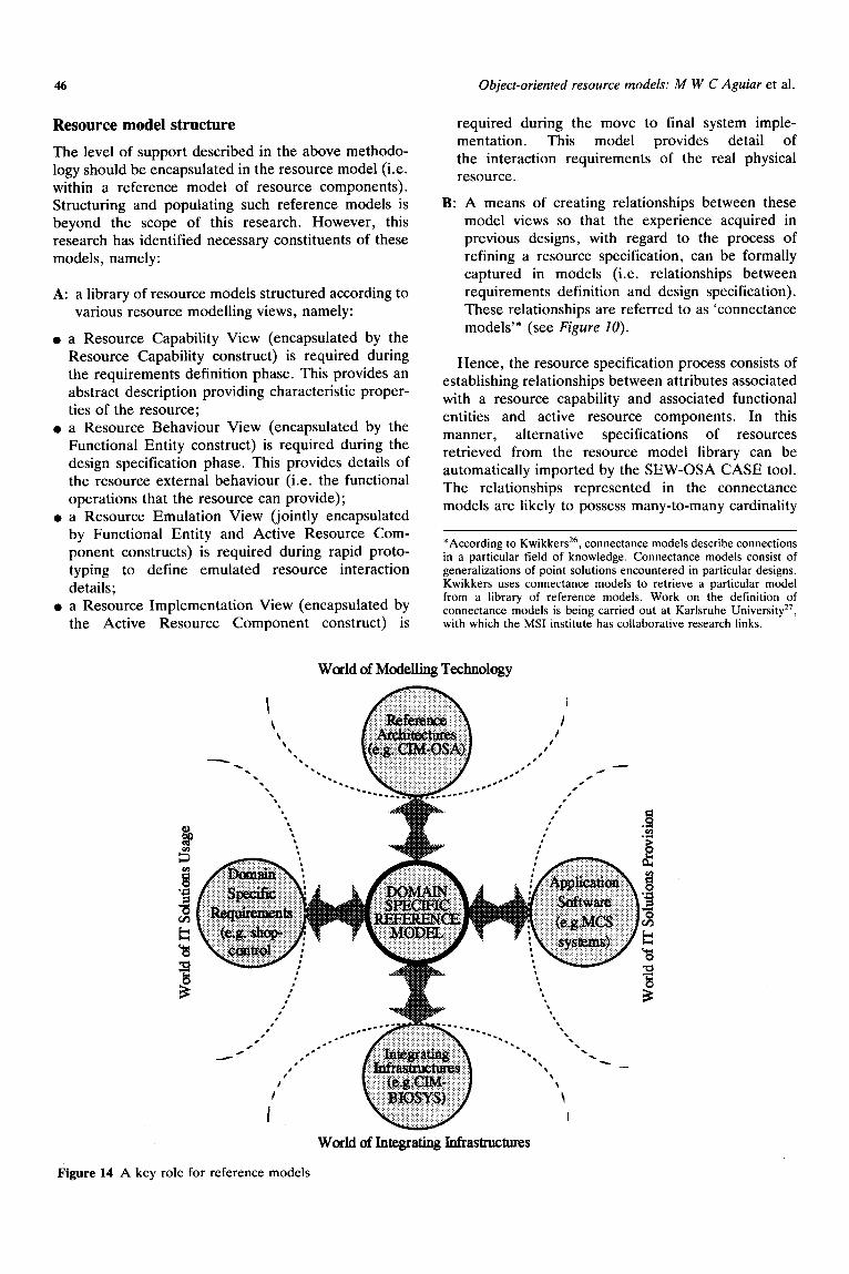
Importance of reference models
The way in which SEW-OSA is used to support
resource component selection is based on the selection of resource models which enable a link to be established between models created during the ‘conceptual analysis’
and the ‘design and implementation’ phases. At the interface between these two phases, reference models produced under the umbrella of an architecture play an
important role in bringing together:
the requirements associated with a particular problem domain (i.e. the world of IT usage);
the solutions that can be used to address those requirements (i.e. the world of IT supply); and;
the means by which solutions can be put to work (i.e. the world of integrating infrastructures).
Such a role for a reference model is illustrated in Figure 14.
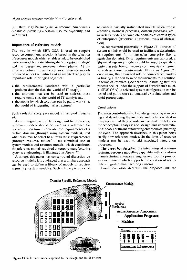
As an integral part of the design and build process, reference models should be used as a reference for decisions upon how to describe the requirements of a
certain domain (through using system models), and what resources to select to address those requirements (through resource models). This combined use of system models and resource models, which constitutes
the reference models required to support manufacturing systems engineering, is illustrated in Figure 15.
Although this paper has concentrated discussion on
resource models, it is envisaged that a similar approach can be used to define a library of models of require- ments (i.e. system models). Such a library is expected
Domain Specific Reference Models
47
to contain partially instantiated models of enterprise
activities, business processes, domain processes, etc.,
as well as models of complete domains of certain types
of enterprises (described at various levels of abstrac-
tion). As represented pictorially in Figure 15, libraries of
system models could be used to facilitate a description of requirements for a particular enterprise (i.e. a particular domain). Once requirements are captured, a
library of resource models could be used to specify a particular selection of resource components configured to address those requirements. Notice in Figure 15,
once again, the envisaged role of connectance models in linking a refined form of requirements to a solution
in terms of resource specifications. Assuming that this process occurs under the support of a workbench (such as SEW-OSA), a selected system configuration can be tested and put to work automatically via simulation and
rapid-prototyping.
Conclusions
The main contributions to knowledge made by conceiv- ing and developing the methods and tools described in this paper is that they provide an essential link between
the ‘conceptual analysis’ and ‘design and implementa- tion’ phases of the manufacturing enterprise engineering life-cycle. The approach described in this paper helps clarify how reference models (in the form of resource models) can be used to aid associated integration
processes. The paper has described the integration of a manu-
facturing resource modelling capability with a top down manufacturing enterprise engineering tool to provide
an environment which supports the creation of realiz- able integrated manufacturing systems.
Limitations associated with the proposed link are
Conne~tance Models
Active Rf2sourc.e Components:
Application Programs
- Machines
Figure 15 Reference models applied to the design and build process
48 Object-oriented resource models: M W C Aguiar et al.
related to the fact that, as yet, only a limited amount of information about different types of resources and their requirements have been formalized in the CASE tools. In other words, not enough reference models are currently available, so that full advantage can be taken of the method proposed.
Instrument Society of America, Research Triangle Park, NC Pw
3 Vallespire, B, Chen, D, Manettin, M and Doumeingts, G ‘Definition of a CIM architecture within the ESPRIT Project IMPACS’, in Computer Applications in Production Engineering: Integration Asoects, Elsevier, Amsterdam (1991) pp 731-738
The paper has highlighted the necessary influence of the modelling of real manufacturing resources on the formal processes of top down enterprise re-engineering. This influence increases as the engineering process approaches system implementation and can be classified in line with the life-cycle phases as follows:
4 Scheer, A W *and ‘Kruse, d ‘ARIS-framework and toolset: a comprehensive business process reengineering methodology’, Proc. 3rd Int. Conf. Automation, Robotics and Computer Vision, ICARV’94, Singapore (November 1994) pp 327-331
5 Aguiar, M W C “An ‘approach to enacting business process models in suooort of the life cvcle of integrated manufacturing systems’, Do& of Philosophy Thesis, Loughborough University (1995)
6 Booeh, G Object Oriented Design with Applications, Benjamin/ Cummins, USA (1991)
Resource Capability Model View - required during the requirements definition phase. Resource Behaviour Model View - required during the design specification phase. Resource Emulation Model View - required during rapid prototyping. Resource Implementation Model View - required during the move to final system implementation.
Finally, it should be stated that the approach described in this paper implies a more forward looking view of the necessary provision of information by suppliers about their resource components. Using an analogy with electronic design, integrated circuit manufacturers are increasingly required to provide models of their components to support the product design lifecycle. In the same way, manufacturing equipment vendors would be required to provide testable models of the resource components they supply, rather than merely catalogues with data about features and behaviour of resource components which cannot be tested. Modules of resource components associated with such models are expected to be available in the market on an ‘off-the-shelf’ basis (e.g. software objects generated via the OMG initiative). Modularity, in this case, implies a twofold requirement: provision of well established interfaces between the modules that comprise a resource component and its external environment; and provision of models that describe the form in which the resource component behaves internally.
Acknowledgements
The authors wish to acknowledge the contributions of other MS1 researchers to this work. In particular, I Coutts, P Clements and P Gilders who were respons- ible for the creation of workbenches within the Model Driven Toolset, and R Weston who heads the MS1 Research Institute.
References
1 ESPRIT/AMICE ‘CIM-OSA Architecture Description’ AD 1.0.2 (1993)
2 Williams, T J The Purdue Enterprise Reference Architecture,
7 IS0 15010303 Part I1 Information Modelling Language EXPRESS (1993)
8 Aguiar, M W, Murgatroyd, I S, Gilders, P J and Weston, R H ‘Model-driven CIM - frameworks, methods and architectures to support the CIM system lifecycle’, Proc. CIM-OSA Workshop on Business Re-engineering, Aachen, Germany (September 1994)
9 Kimura, F ‘Product and process modelling as a kernal for virtual manufacturine. environment’. Ann. CIRP, Vol 42 (1993) pp 147-155 -
10 IS0 TC184 SC4 WG8/N13 Project 2: Resource Usage Manage- ment. Draft Scone oresented at London meeting by B R Katzy (June 1992) ’ ’
11 ESPRIT/VOICE Validation of CIM-OSA (Open Systems Archi- tecture) - A joint ESPRIT projects report (1995)
12 SEMATECH Computer Integrated Manufacturing (CIM) Applica- tion Framework Specification I. 1, SEMATECH Technology Transfer 93061697D-ENG (1994)
t3 Molina, A, Ellis, T I A, Young, R and Bell, R ‘Modelling manufacturing resources, processes and strategies to support concurrent engineering’, Conf. on Concurrent Engineering: Research and Applications, Pittsburgh, PA (August 2%31 1994)
14 Bjorke, 0 and Myklehust, 0 IMPACT: Integrated Modelling of Products and Process using Advanced Computer Technologies, TAPIR Publishers, Trondheim, Norway (1992)
15 Al-Ashaah, A and Young, R I M - ‘Information models: an aid to concurrency in iniection moulded oroducts design’, Winter Ann.
16
11
18
19
20
21 22
23
24
25 26
27
Meeting ASME, Anaheim, CA (November 8-13 1992) ESPRIT/AIT ESPRIT Project 7704 Advanced Information Tech- nology in Design and Manufacturing, Management Overview of the First Phase (November 1993-April 1994), The AIT Consor- tium, ref AITP/20OO/DB/PROJ/58_2.DOC (1994) Clements, P, Coutts, I and Weston, R H ‘A life-cycle support environment comprising open systems manufacturing modelling methods and the CIM-BIOSYS infrastructure tools’, MAPLE’93 - Symposium on Man@, Automation Programming Language Environments, Ottawa, Canada (1993) Aguiar, M W C and Weston, R H ‘A model-driven approach to enterprise integration’, ht. J. Computer Integrated Manufacturing Vol 8, No 3, pp 210-224 (1995) Coutts, I A et al. ‘Open applications within soft integrated manufacturing systems’, Proc. In?. Conf. Manu. Automation, Hong Kong (1992) Aguiar, M W C, Coutts, I A and Weston, R H ‘Rapid prototyping of integrated manufacturing systems by accomplishing model- enactment’, Proc. Inst. Elect. Eng. Vol 1, No 4, pp 299-314 (1995) ESPRIT/AMICE CIM-OSA formal reference base (1993) Aguiar, M W C and Weston, R H ‘CIM-OSA and stochastic time Petri nets for behavioural modelling and model handling in CIM systems design and building’, Proc. ZMechE Part b, J. Eng. Manu. Vol207 No 3 (1993) pp 147-158 IS0 9074 Estelle: A Formal Description Technique Based on an Extended State Transition Model (1988) Enterprise Integration Modelling 1992 - Proc. First Int. Conf., Hilton Head Island, SC (May 1992) IS0 DIS-10303 Part 21 STEP Physical File Format (1994) Kwikkers, R and Wortmann, J C ‘The FOF modelling framework’, Proc. Int. Con& Enterprise Integration Modelling (ICEIMT 92), USA (1992) pp 259-265 Naeger, G ‘An integrated approach to software systems planning and selection based + on CIMOSA-models’, Department of Computer Science, University of Karlsruhe, Internal Paper (1993)


![Object-oriented Programming with PHP · Object-oriented Programming with PHP [2 ] Object-oriented programming Object-oriented programming is a popular programming paradigm where concepts](https://img.pdfslide.net/doc/110x75/5e1bb46bfe726d12f8517bf0/object-oriented-programming-with-php-object-oriented-programming-with-php-2-object-oriented.jpg)